EP3339934A1 - Head-mounted electronic device - Google Patents
Head-mounted electronic device Download PDFInfo
- Publication number
- EP3339934A1 EP3339934A1 EP15901487.7A EP15901487A EP3339934A1 EP 3339934 A1 EP3339934 A1 EP 3339934A1 EP 15901487 A EP15901487 A EP 15901487A EP 3339934 A1 EP3339934 A1 EP 3339934A1
- Authority
- EP
- European Patent Office
- Prior art keywords
- axis
- electronic device
- head mounted
- mounted electronic
- coupling
- Prior art date
- Legal status (The legal status is an assumption and is not a legal conclusion. Google has not performed a legal analysis and makes no representation as to the accuracy of the status listed.)
- Withdrawn
Links
Images



Classifications
-
- G—PHYSICS
- G02—OPTICS
- G02B—OPTICAL ELEMENTS, SYSTEMS OR APPARATUS
- G02B27/00—Optical systems or apparatus not provided for by any of the groups G02B1/00 - G02B26/00, G02B30/00
- G02B27/01—Head-up displays
- G02B27/017—Head mounted
- G02B27/0176—Head mounted characterised by mechanical features
-
- H—ELECTRICITY
- H04—ELECTRIC COMMUNICATION TECHNIQUE
- H04R—LOUDSPEAKERS, MICROPHONES, GRAMOPHONE PICK-UPS OR LIKE ACOUSTIC ELECTROMECHANICAL TRANSDUCERS; ELECTRIC HEARING AIDS; PUBLIC ADDRESS SYSTEMS
- H04R1/00—Details of transducers, loudspeakers or microphones
- H04R1/10—Earpieces; Attachments therefor ; Earphones; Monophonic headphones
- H04R1/1058—Manufacture or assembly
- H04R1/1066—Constructional aspects of the interconnection between earpiece and earpiece support
-
- G—PHYSICS
- G02—OPTICS
- G02B—OPTICAL ELEMENTS, SYSTEMS OR APPARATUS
- G02B27/00—Optical systems or apparatus not provided for by any of the groups G02B1/00 - G02B26/00, G02B30/00
- G02B27/01—Head-up displays
- G02B27/0149—Head-up displays characterised by mechanical features
- G02B2027/015—Head-up displays characterised by mechanical features involving arrangement aiming to get less bulky devices
-
- H—ELECTRICITY
- H04—ELECTRIC COMMUNICATION TECHNIQUE
- H04R—LOUDSPEAKERS, MICROPHONES, GRAMOPHONE PICK-UPS OR LIKE ACOUSTIC ELECTROMECHANICAL TRANSDUCERS; ELECTRIC HEARING AIDS; PUBLIC ADDRESS SYSTEMS
- H04R1/00—Details of transducers, loudspeakers or microphones
- H04R1/10—Earpieces; Attachments therefor ; Earphones; Monophonic headphones
- H04R1/1008—Earpieces of the supra-aural or circum-aural type
-
- H—ELECTRICITY
- H04—ELECTRIC COMMUNICATION TECHNIQUE
- H04R—LOUDSPEAKERS, MICROPHONES, GRAMOPHONE PICK-UPS OR LIKE ACOUSTIC ELECTROMECHANICAL TRANSDUCERS; ELECTRIC HEARING AIDS; PUBLIC ADDRESS SYSTEMS
- H04R5/00—Stereophonic arrangements
- H04R5/033—Headphones for stereophonic communication
- H04R5/0335—Earpiece support, e.g. headbands or neckrests
Definitions
- the present disclosure relates to head mounted electronic devices, and more particularly to a head mounted electronic device with a headphone and a display portion which are operable to rotate relative to each other.
- Head mounted electronic device is a near-eye display device. It produces images and projects the images to the eyes of a user, so that the user can see magnified images, and a display effect of large area can be obtained.
- Most of the existing head mounted electronic devices have their audio signals transmitted to the user via earplugs arranged thereon, but the acoustic effect obtained from the earplugs is not satisfactory.
- headphone jacks for the user to plug in headphones with desired acoustic effects.
- this solution makes it difficult to wear, and also inconvenient to carry the headphone and the head mounted electronic device separately.
- embodiments of the present disclosure provide a head mounted electronic device with a headphone and a display portion which are operable to rotate relative to each other.
- a head mounted electronic device includes a headphone and a display portion.
- the headphone includes an elastic belt which is of C-shape and includes two coupling ends, two movable members each rotatably coupled to a corresponding coupling end around a first axis, and two speakers each rotatably coupled to a corresponding movable member around a second axis.
- the display portion includes a main body to produce images and project the images outwardly, and two coupling members coupled to two opposite ends of the main body and each rotatably coupled to a corresponding speaker around a third axis.
- the display portion can enable the speaker to rotate around the first axis and the second axis, so that twisting of the elastic belt and the coupling members can be avoided, and the display portion can be rotated to a position where the display portion and the headphone substantially overlap with each other.
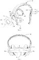
- FIG. 1 is a schematic view of a head mounted electronic device 10 in accordance with a first embodiment of the present disclosure.
- the head mounted electronic device 10 may be a head mounted videoplayer, a head mounted game machine, a head mounted navigator, etc..
- the head mounted electronic device 10 includes a headphone 20 and a display portion 40.
- the display portion 40 is rotatably coupled to the headphone 20.
- the display portion 40 can be rotated to a position where an included angle defined between the display portion 40 and the headphone 20 is substantially 90 degrees, as illustrated by FIG. 1 .
- the display portion 40 is located in front of his/her eyes and projects images to the eyes.
- the display portion 40 can be rotated to a position where the display portion 40 substantially overlap with the headphone 20 to facilitate to store the head mounted electronic device 10, as illustrated by FIG. 5 .
- the headphone 20 includes two speakers 22, an elastic belt 24, and two movable members 26 to rotatably couple the two speakers 22 to the elastic belt 24.
- the elastic belt 24 is substantially C-shaped and includes two coupling ends 25 located at a C-shaped opening.
- the elastic belt 24 can enable the two coupling ends 25 to get close to or away from each other.
- each coupling end 25 includes a receiving part 25a and a first sliding member 25b slidably received in the receiving part 25a.
- a first protrusion post 25c extends from a side of the first sliding member 25b away from the receiving part 25a.
- the first sliding member 25b can be partially slid out of the receiving part 25a.
- the first protrusion post 25c defines a first axis 25d.
- the first sliding member 25b is arranged to allow the user to adjust a distance between the elastic belt 24 and the speaker 22. However, it can be understood that, when the elastic belt 24 is stretchable, or the distance between the elastic belt 24 and speaker 22 does not need to be adjusted, the first sliding member 25b can be omitted.
- Each movable member 26 is rotatably coupled to a corresponding coupling end 25 around the first axis 25d, so that the movable member 26 can be rotated relative to the corresponding coupling end 25 with the first axis 25d as a rotation axis.
- the movable member 26 is substantially curved in shape, and includes a curved main portion 26a, a first hole 26b inwardly concaved from an end of the main portion 26a adjacent to the coupling end 25, and a second protrusion post 26c extending from an opposite end of the main portion 26a and toward the speaker 22.
- the first protrusion post 25c is inserted and locked into the first hole 26b, so that the first protrusion post 25c can be rotated within the first through hole 25a.
- each speaker 22 is rotatably coupled to a corresponding movable member 26 around a second axis 26d, so that the speaker 22 can be rotated relative to the corresponding movable member 26 with the second axis 26d as a rotation axis.
- each speaker 22 includes an inner wall 22a to transmit sound, an outer wall 22b opposite to the inner wall 22a, and a side wall 22c extending from a periphery of the outer wall 22b and toward the inner wall 22a.
- the outer wall 22b and the side wall 22c cooperatively define a cavity (not shown).
- the speaker 22 has a trumpet (not shown) located in the cavity, and a side of the trumpet producing sound faces the inner wall 22a.
- the side wall 22c defines a second through hole 22d.
- the second protrusion post 26c is inserted into the second through hole 22d and locked in the cavity, so that the speaker 22 can be rotated relative to the second protrusion post 26c, that is to say, the second protrusion post 26c defines the second axis 26d.
- the second axis 26d and the first axis 25d define a first included angle ⁇ therebetween.
- the speaker 22 and the movable member 26 can be rotated around the first axis 25d, and the speaker 22 can be further rotated around the second axis 26d, so that the moveable member 26 can be rotated in multiple dimensions.
- the arrangement of the protrusion posts 25c, 26c and the recesses 26b and 22d can be reversed.
- the movable members include the first protrusion posts 25c, and the two first recesses 26b are defined in the coupling ends 25.
- the display portion 40 includes a main body 42 and two coupling members 44.
- the main body 42 is to produce images and project the images outwardly.
- the main body 42 is provided with an image producing device and an optical module (not shown). Images produced by the image producing device are projected in preset directions by the optical module.
- the main body 42 is further provided with an adjusting mechanism (not shown).
- the adjusting mechanism is to adjust a distance between the image producing device and the optical module, to thereby fit near-sighted or far-sighted users.
- the adjusting mechanism can be further to adjust a distance between two combinations of the image producing devices and the optical modules, to thereby fit interpupillary distances of different users.
- the two coupling members 44 are coupled to two opposite ends of the main body 42 and each is also rotatably coupled to a corresponding speaker 22 around a third axis 22e.
- the third axis 22e extends from the outer wall 22b of the speaker 22 and toward the inner wall 22a of the speaker 22.
- the display portion 40 can be rotated to a position where the display portion 40 is apart away from the headphone 20, as illustrated by FIG. 1 , and a position where the display portion 40 and the headphone 20 substantially overlap with each other, as illustrated by FIG. 5 .
- the side wall 22c of the speaker 22 is a cylindrical wall.
- An end of the coupling member 44 adjacent to the speaker 22 is provided with a ring 44a.
- the ring 44a also has a cylindrical wall.
- the ring 44a is coupled to the side wall 22c of the speaker 22 by a clamping member 44b. Thus, the ring 44a can be rotated around a central axis of the side wall 22c. Thus, the side wall 22c of the speaker 22 defines the third axis 22e.
- the third axis 22e is substantially perpendicular to a corresponding first axis 25d and/or a corresponding second axis 26d.
- the display portion 40 can be rotated to the position where the included angle defined between the display portion 40 and the headphone 20 is substantially 90 degrees.
- 90 degrees is just an example, and the degrees may be changed due to different wearing habits of users, for example, the included angle may be 70 degrees, 80 degrees, 100 degrees, or others.
- ends of the two speakers 22 away from the elastic belt 24 are inclined toward each other, as illustrated by FIG. 3 .
- the third axes 22e of the two speakers 22 define a second included angle ⁇ therebetween.
- the arrangement of the incline that is, the second included angle ⁇
- the display portion 40 when it needs to rotate the display portion 40 to the position where the display portion 40 and the headphone 20 substantially overlap with each other, the display portion 40 is rotated in an upward direction as shown in FIG. 3 . Because the third axis 22e is inclined relative to a horizontal direction in FIG. 3 , and the main body 42 cannot be stretched, during the upward rotation of the display portion 40, the right speaker 22 shown in FIG. 1 and FIG. 3 are caused to rotate counterclockwise (shown by an arrow located at the second axis 26d in FIG. 1 ) around the second axis 26d. That is to say, a side of the right speaker 22 adjacent to the first hole 26b is rotated in a direction toward the other speaker 22.
- the other speaker 22 is rotated in an opposite direction. Also, the upward rotation of the display portion 40 further causes the right speaker 22 and the right coupling member 26 shown in FIG. 1 and FIG. 3 to rotate in a direction (shown by an arrow located at the first axis 25d) around the first axis 25d. That is to say, a side of the speaker 22 adjacent to the second protrusion post 26c is rotated in a direction away from the other speaker 22.
- the speaker 22 is more comfortable for ears, to thereby provide better audio effect for users.
- the third axis 22e is not horizontally arranged any more, i.e., the two third axes 22e are not collinear and define an included angle therebetween, the rotation of the display portion 40 relative to the headphone 20 becomes complicated.
- the elastic belt 24 is directly fixed to the speakers 22, that is to say, when the movable members 26 are omitted, the elastic belt 24 and the coupling members 44 are twisted in rotation.
- the rotation of the speaker 22 along two dimensions permits the speaker 22 to rotate around the first axis 25d and the second axis 26d in the rotation when compelled by the movement of the display portion 40, to thereby avoid twisting the elastic belt 24 and the coupling member 44, and make the display portion 40 to rotate to the position where the display portion 40 and the headphone 20 substantially overlap with each other.
- the main portion 26a of the movable member 26 substantially extends about one quarter of a circle, that is to say, the first included angle ⁇ is approximately 90 degrees.
- the first included angle ⁇ is not limited to 90 degrees.
- the first included angle is larger than 30 degrees but less than 150 degrees, or is larger than 210 degrees but less than 330 degrees. At this point, a length of the main portion 26a can be accordingly changed.
- the second included angle ⁇ is substantially 150 degrees when the head mounted electronic device 10 is not subject to any external force. However it can be understood that, for different users, the degrees can be changed, so long as that the headphone 20 is more comfortable for ears.
- the second included angle ⁇ is preferably larger than 100 degrees but less than 170 degrees.
- each of the coupling members 44 can be parallelly coupled to the main body 42 or the speaker 22, so that each coupling member 44 can be moved to a first position adjacent to the main body 42 or the speaker 22 and moved to a second position away from the main body 42 or the speaker 22. Therefore, a distance between the main body 42 and user eyes can be adjusted.
- the display portion 40 further includes supporting members 46 extending outwardly from two opposite ends of the main body 42, and the coupling member 44 can be slidably coupled to the supporting member 46, so that the main body 42 can be moved to be close to or away from the speakers 22.
- a manner in which the coupling member 44 is parallelly and movably coupled to the speaker 22 is similar to the structure connection principle of the aforesaid way, and will not be repeated herein.
- first means two or more than two, unless there is a specific limitation.
- the terms “mount”, “connected” and “connection” should be broadly understood, for example, it may be a fixed connection, or may be a detachable connection, or an integral connection; it may be directly connected, or may be indirectly connected via intermediary, or may be communication between interiors of two elements or interactions between two elements.
- the terms “mount”, “connected” and “connection” should be broadly understood, for example, it may be a fixed connection, or may be a detachable connection, or an integral connection; it may be directly connected, or may be indirectly connected via intermediary, or may be communication between interiors of two elements or interactions between two elements.
Landscapes
- Physics & Mathematics (AREA)
- Engineering & Computer Science (AREA)
- Acoustics & Sound (AREA)
- Signal Processing (AREA)
- General Physics & Mathematics (AREA)
- Optics & Photonics (AREA)
- Manufacturing & Machinery (AREA)
- Headphones And Earphones (AREA)
- Details Of Audible-Bandwidth Transducers (AREA)
- Health & Medical Sciences (AREA)
- Otolaryngology (AREA)
Abstract
Description
- The present disclosure relates to head mounted electronic devices, and more particularly to a head mounted electronic device with a headphone and a display portion which are operable to rotate relative to each other.
- Head mounted electronic device is a near-eye display device. It produces images and projects the images to the eyes of a user, so that the user can see magnified images, and a display effect of large area can be obtained. Most of the existing head mounted electronic devices have their audio signals transmitted to the user via earplugs arranged thereon, but the acoustic effect obtained from the earplugs is not satisfactory. Thus, in view of the above, some products are provided with headphone jacks for the user to plug in headphones with desired acoustic effects. However, this solution makes it difficult to wear, and also inconvenient to carry the headphone and the head mounted electronic device separately.
- In view of the above, embodiments of the present disclosure provide a head mounted electronic device with a headphone and a display portion which are operable to rotate relative to each other.
- A head mounted electronic device includes a headphone and a display portion. The headphone includes an elastic belt which is of C-shape and includes two coupling ends, two movable members each rotatably coupled to a corresponding coupling end around a first axis, and two speakers each rotatably coupled to a corresponding movable member around a second axis. The display portion includes a main body to produce images and project the images outwardly, and two coupling members coupled to two opposite ends of the main body and each rotatably coupled to a corresponding speaker around a third axis.
- In the present disclosure, by setting the moveable members, during a rotation around the third axis, the display portion can enable the speaker to rotate around the first axis and the second axis, so that twisting of the elastic belt and the coupling members can be avoided, and the display portion can be rotated to a position where the display portion and the headphone substantially overlap with each other.
- The following accompanying drawings are used for illustrating embodiments of the present disclosure in detail in combination with specific embodiments. It should be understood that, components in the accompanying drawings do not represent actual sizes and proportion relationships, they are just to clearly illustrate the embodiments, and should not be understood as limitation to the present disclosure.
-
FIG. 1 is a structural view of a head mounted electronic device in accordance with an embodiment of the present disclosure, showing a headphone and a display portion in an unfolded state. -
FIG. 2 is a partially exploded view of the head mounted electronic device ofFIG. 1 . -
FIG. 3 is a front view of the head mounted electronic device ofFIG. 1 . -
FIG. 4 is a side view of the head mounted electronic device ofFIG. 1 . -
FIG. 5 is a structural view of the head mounted electronic device ofFIG. 1 , showing the headphone and the display portion in a folded state. - In order to make the purpose, technical solution, and advantages of the present disclosure clearer, the following will further illustrate the present disclosure in combination with various embodiments and the accompanying drawings. It should be understood that, the specific embodiments described herein are only used for explaining the present disclosure, and are not used for limiting the present disclosure. In addition, the content shown in the accompanying drawings does not represent actual proportion relationships between components of the present disclosure, and are just for illustrating. It shall be pointed out that, in the present disclosure, the mentioned "connection" or "coupling" between two components may not be a direct connection, and also may be an indirect connection through a third component.
- Referring to
FIG. 1, FIG. 1 is a schematic view of a head mountedelectronic device 10 in accordance with a first embodiment of the present disclosure. The head mountedelectronic device 10 may be a head mounted videoplayer, a head mounted game machine, a head mounted navigator, etc.. The head mountedelectronic device 10 includes aheadphone 20 and adisplay portion 40. Thedisplay portion 40 is rotatably coupled to theheadphone 20. Thus, when in use, thedisplay portion 40 can be rotated to a position where an included angle defined between thedisplay portion 40 and theheadphone 20 is substantially 90 degrees, as illustrated byFIG. 1 . At this point, after the user puts theheadphone 20 on his/her head, thedisplay portion 40 is located in front of his/her eyes and projects images to the eyes. When not being used, thedisplay portion 40 can be rotated to a position where thedisplay portion 40 substantially overlap with theheadphone 20 to facilitate to store the head mountedelectronic device 10, as illustrated byFIG. 5 . - Specifically, referring to
FIG. 1 andFIG. 2 , theheadphone 20 includes twospeakers 22, anelastic belt 24, and twomovable members 26 to rotatably couple the twospeakers 22 to theelastic belt 24. Theelastic belt 24 is substantially C-shaped and includes two coupling ends 25 located at a C-shaped opening. Theelastic belt 24 can enable the two coupling ends 25 to get close to or away from each other. In the embodiment, each coupling end 25 includes a receivingpart 25a and a first sliding member 25b slidably received in thereceiving part 25a. Afirst protrusion post 25c extends from a side of the first sliding member 25b away from thereceiving part 25a. The first sliding member 25b can be partially slid out of thereceiving part 25a. Thefirst protrusion post 25c defines afirst axis 25d. The first sliding member 25b is arranged to allow the user to adjust a distance between theelastic belt 24 and thespeaker 22. However, it can be understood that, when theelastic belt 24 is stretchable, or the distance between theelastic belt 24 andspeaker 22 does not need to be adjusted, the first sliding member 25b can be omitted. - Each
movable member 26 is rotatably coupled to a corresponding coupling end 25 around thefirst axis 25d, so that themovable member 26 can be rotated relative to the corresponding coupling end 25 with thefirst axis 25d as a rotation axis. In the embodiment, themovable member 26 is substantially curved in shape, and includes a curvedmain portion 26a, afirst hole 26b inwardly concaved from an end of themain portion 26a adjacent to the coupling end 25, and asecond protrusion post 26c extending from an opposite end of themain portion 26a and toward thespeaker 22. Thefirst protrusion post 25c is inserted and locked into thefirst hole 26b, so that thefirst protrusion post 25c can be rotated within the first throughhole 25a. - Each
speaker 22 is rotatably coupled to a correspondingmovable member 26 around asecond axis 26d, so that thespeaker 22 can be rotated relative to the correspondingmovable member 26 with thesecond axis 26d as a rotation axis. In the embodiment, eachspeaker 22 includes aninner wall 22a to transmit sound, anouter wall 22b opposite to theinner wall 22a, and aside wall 22c extending from a periphery of theouter wall 22b and toward theinner wall 22a. Theouter wall 22b and theside wall 22c cooperatively define a cavity (not shown). Thespeaker 22 has a trumpet (not shown) located in the cavity, and a side of the trumpet producing sound faces theinner wall 22a. Theside wall 22c defines a second throughhole 22d. Thesecond protrusion post 26c is inserted into the second throughhole 22d and locked in the cavity, so that thespeaker 22 can be rotated relative to thesecond protrusion post 26c, that is to say, thesecond protrusion post 26c defines thesecond axis 26d. Thesecond axis 26d and thefirst axis 25d define a first included angle α therebetween. Thus, thespeaker 22 and themovable member 26 can be rotated around thefirst axis 25d, and thespeaker 22 can be further rotated around thesecond axis 26d, so that themoveable member 26 can be rotated in multiple dimensions. It should be pointed out that, the arrangement of theprotrusion posts recesses first protrusion posts 25c, and the twofirst recesses 26b are defined in the coupling ends 25. - The
display portion 40 includes amain body 42 and twocoupling members 44. Themain body 42 is to produce images and project the images outwardly. Specifically, themain body 42 is provided with an image producing device and an optical module (not shown). Images produced by the image producing device are projected in preset directions by the optical module. Themain body 42 is further provided with an adjusting mechanism (not shown). The adjusting mechanism is to adjust a distance between the image producing device and the optical module, to thereby fit near-sighted or far-sighted users. The adjusting mechanism can be further to adjust a distance between two combinations of the image producing devices and the optical modules, to thereby fit interpupillary distances of different users. - The two
coupling members 44 are coupled to two opposite ends of themain body 42 and each is also rotatably coupled to acorresponding speaker 22 around athird axis 22e. Thethird axis 22e extends from theouter wall 22b of thespeaker 22 and toward theinner wall 22a of thespeaker 22. Thus, thedisplay portion 40 can be rotated to a position where thedisplay portion 40 is apart away from theheadphone 20, as illustrated byFIG. 1 , and a position where thedisplay portion 40 and theheadphone 20 substantially overlap with each other, as illustrated byFIG. 5 . In the embodiment, theside wall 22c of thespeaker 22 is a cylindrical wall. An end of thecoupling member 44 adjacent to thespeaker 22 is provided with aring 44a. Thering 44a also has a cylindrical wall. Thering 44a is coupled to theside wall 22c of thespeaker 22 by a clampingmember 44b. Thus, thering 44a can be rotated around a central axis of theside wall 22c. Thus, theside wall 22c of thespeaker 22 defines thethird axis 22e. Thethird axis 22e is substantially perpendicular to a correspondingfirst axis 25d and/or a correspondingsecond axis 26d. - As illustrated in
FIG. 1 , when the head mountedelectronic device 10 is assembled and in use, without any external force, thedisplay portion 40 can be rotated to the position where the included angle defined between thedisplay portion 40 and theheadphone 20 is substantially 90 degrees. It should be pointed out that, 90 degrees is just an example, and the degrees may be changed due to different wearing habits of users, for example, the included angle may be 70 degrees, 80 degrees, 100 degrees, or others. At this point, ends of the twospeakers 22 away from theelastic belt 24 are inclined toward each other, as illustrated byFIG. 3 . Thus, at this point thethird axes 22e of the twospeakers 22 define a second included angle β therebetween. The arrangement of the incline (that is, the second included angle β) can make thespeakers 22 be more comfortable for ears. - Referring to
FIG. 1 andFIG. 3 , when it needs to rotate thedisplay portion 40 to the position where thedisplay portion 40 and theheadphone 20 substantially overlap with each other, thedisplay portion 40 is rotated in an upward direction as shown inFIG. 3 . Because thethird axis 22e is inclined relative to a horizontal direction inFIG. 3 , and themain body 42 cannot be stretched, during the upward rotation of thedisplay portion 40, theright speaker 22 shown inFIG. 1 andFIG. 3 are caused to rotate counterclockwise (shown by an arrow located at thesecond axis 26d inFIG. 1 ) around thesecond axis 26d. That is to say, a side of theright speaker 22 adjacent to thefirst hole 26b is rotated in a direction toward theother speaker 22. Theother speaker 22 is rotated in an opposite direction. Also, the upward rotation of thedisplay portion 40 further causes theright speaker 22 and theright coupling member 26 shown inFIG. 1 andFIG. 3 to rotate in a direction (shown by an arrow located at thefirst axis 25d) around thefirst axis 25d. That is to say, a side of thespeaker 22 adjacent to thesecond protrusion post 26c is rotated in a direction away from theother speaker 22. - It can be known from the aforesaid description, in the embodiment, by setting the second included angle β, the
speaker 22 is more comfortable for ears, to thereby provide better audio effect for users. However, since thethird axis 22e is not horizontally arranged any more, i.e., the twothird axes 22e are not collinear and define an included angle therebetween, the rotation of thedisplay portion 40 relative to theheadphone 20 becomes complicated. At this point, when theelastic belt 24 is directly fixed to thespeakers 22, that is to say, when themovable members 26 are omitted, theelastic belt 24 and thecoupling members 44 are twisted in rotation. However, in the embodiment, since theheadphone 20 is provided with themovable members 26, the rotation of thespeaker 22 along two dimensions permits thespeaker 22 to rotate around thefirst axis 25d and thesecond axis 26d in the rotation when compelled by the movement of thedisplay portion 40, to thereby avoid twisting theelastic belt 24 and thecoupling member 44, and make thedisplay portion 40 to rotate to the position where thedisplay portion 40 and theheadphone 20 substantially overlap with each other. - In the embodiment, the
main portion 26a of themovable member 26 substantially extends about one quarter of a circle, that is to say, the first included angle α is approximately 90 degrees. However it can be understood that, under a circumstance that an included angle of other degrees is set, thespeaker 22 can also be rotated along two dimensions to achieve the aforesaid purpose. Therefore, the first included angle α is not limited to 90 degrees. Preferably, the first included angle is larger than 30 degrees but less than 150 degrees, or is larger than 210 degrees but less than 330 degrees. At this point, a length of themain portion 26a can be accordingly changed. - In the embodiment, the second included angle β is substantially 150 degrees when the head mounted
electronic device 10 is not subject to any external force. However it can be understood that, for different users, the degrees can be changed, so long as that theheadphone 20 is more comfortable for ears. The second included angle β is preferably larger than 100 degrees but less than 170 degrees. - Preferably, each of the
coupling members 44 can be parallelly coupled to themain body 42 or thespeaker 22, so that each couplingmember 44 can be moved to a first position adjacent to themain body 42 or thespeaker 22 and moved to a second position away from themain body 42 or thespeaker 22. Therefore, a distance between themain body 42 and user eyes can be adjusted. Specifically, referring toFIG. 4 , take that thecoupling member 44 is parallelly and movably coupled to themain body 42 for an example, thedisplay portion 40 further includes supportingmembers 46 extending outwardly from two opposite ends of themain body 42, and thecoupling member 44 can be slidably coupled to the supportingmember 46, so that themain body 42 can be moved to be close to or away from thespeakers 22. A manner in which thecoupling member 44 is paralelly and movably coupled to thespeaker 22 is similar to the structure connection principle of the aforesaid way, and will not be repeated herein. - In the description of the present disclosure, the "first", "second" are merely used for description, and cannot be understood to indicate or imply relative importance or implicitly indicate the number of the indicated technical features. Therefore, features with a limitation of "first" or "second" can explicitly or implicitly include one or more features. In the description of the present disclosure, "multiple" means two or more than two, unless there is a specific limitation.
- In the description of the present disclosure, it should be noted that, unless explicitly stated or limited, the terms "mount", "connected" and "connection" should be broadly understood, for example, it may be a fixed connection, or may be a detachable connection, or an integral connection; it may be directly connected, or may be indirectly connected via intermediary, or may be communication between interiors of two elements or interactions between two elements. Those skilled in the art can understand the specific definition of above terms in the present disclosure according to specific conditions.
- The foregoing description is only the preferred embodiments of the present disclosure, but is not intended to limit the present disclosure. Any modification, alternatives, improvements or the like within the spirit and principles of the present disclosure should be included in the protection scope of the present disclosure.
Claims (13)
- A head mounted electronic device comprising a headphone and a display portion, characterized in that the headphone comprises:an elastic belt being of C-shape and having two coupling ends;two movable members each rotatably coupled to a corresponding coupling end around a first axis; andtwo speakers each rotatably coupled to a corresponding movable member around a second axis, the second axis and the first axis defining a first included angle therebetween; andthe display portion comprises:a main body operable to produce images and project the images outwardly; andtwo coupling members coupled to two opposite ends of the main body and each rotatably coupled to a corresponding speaker around a third axis, the two third axes defining a second included angle therebetween.
- The head mounted electronic device of claim 1, characterized in that each of the speakers comprises an inner wall to transmit sound and an outer wall opposite to the inner wall, a corresponding third axis extends from the inner wall and toward the outer wall.
- The head mounted electronic device of claim 2, characterized in that the movable member comprises a first end rotatably coupled to a corresponding coupling end around the first axis, and a second end rotatably coupled to a corresponding speaker around the second axis, and a curved portion is arranged between the first end and the second end.
- The head mounted electronic device of claim 3, characterized in that each of the two speakers further comprises a side wall extending from a periphery of the outer wall and toward the inner wall, the movable member is rotatably coupled to the side wall around the second axis.
- The head mounted electronic device of claim 3 or claim 4, characterized in that each of the two coupling ends comprises one of a first protrusion post and a first recess, the first end of each of the two movable members comprises the other of the first recess and the first protrusion post, the first protrusion post is rotatably latched in the first recess, and the first axis is defined by the first protrusion post or the first recess.
- The head mounted electronic device of claim 3 or claim 4, characterized in that each of the two speakers comprises one of a second protrusion post and a second recess, the second end of each of the two movable members comprises the other of the second recess and the second protrusion post, the second protrusion post is rotatably latched in the second recess, and the second axis is defined by the second protrusion post or the second recess.
- The head mounted electronic device of claim 4, characterized in that the side wall of each of the two speakers is a cylindrical wall, the third axis is a central axis of the cylindrical wall, and the coupling member is rotatably coupled to the side wall along the third axis.
- The head mounted electronic device of claim 7, characterized in that an end of each of the two coupling members adjacent to a corresponding speaker comprises a second cylindrical wall, the second cylindrical wall is coupled to the side wall of the corresponding speaker, so that the coupling member is operable to rotate around the third axis.
- The head mounted electronic device of claim 1, characterized in that the third axis of each of the two speakers is substantially perpendicular to a corresponding first axis and a corresponding second axis.
- The head mounted electronic device of claim 1, characterized in that the second included angle is larger than 100 degrees and less than 170 degrees.
- The head mounted electronic device of claim 1 or claim 9, characterized in that the first included angle is larger than 30 degrees and less than 150 degrees.
- The head mounted electronic device of claim 1, characterized in that each of the coupling members is parallelly and movably coupled to the main body or the speaker, so that each of the coupling members is operable to move to a first position adjacent to the main body or the speaker and move to a second position away from the main body or the speaker.
- The head mounted electronic device of claim 1, characterized in that each of the two movable members is parallelly and movably coupled to the coupling end, so that each of the movable members is operable to be move to a first position adjacent to the elastic belt and move to a second position away from the elastic belt.
Applications Claiming Priority (1)
| Application Number | Priority Date | Filing Date | Title |
|---|---|---|---|
| PCT/CN2015/087566 WO2017028283A1 (en) | 2015-08-19 | 2015-08-19 | Head-mounted electronic device |
Publications (2)
| Publication Number | Publication Date |
|---|---|
| EP3339934A1 true EP3339934A1 (en) | 2018-06-27 |
| EP3339934A4 EP3339934A4 (en) | 2019-04-10 |
Family
ID=58051541
Family Applications (1)
| Application Number | Title | Priority Date | Filing Date |
|---|---|---|---|
| EP15901487.7A Withdrawn EP3339934A4 (en) | 2015-08-19 | 2015-08-19 | Head-mounted electronic device |
Country Status (6)
| Country | Link |
|---|---|
| US (1) | US10095037B2 (en) |
| EP (1) | EP3339934A4 (en) |
| JP (1) | JP6591659B2 (en) |
| KR (1) | KR102003629B1 (en) |
| CN (1) | CN107003515B (en) |
| WO (1) | WO2017028283A1 (en) |
Families Citing this family (10)
| Publication number | Priority date | Publication date | Assignee | Title |
|---|---|---|---|---|
| JP6689987B2 (en) * | 2015-12-31 | 2020-04-28 | シェンジェン ロイオル テクノロジーズ カンパニー リミテッドShenzhen Royole Technologies Co., Ltd. | Flexible wearable device |
| CN107407809B (en) * | 2016-01-26 | 2020-04-14 | 深圳市柔宇科技有限公司 | Head-mounted device, earphone device, and head-mounted device separation control method |
| US10194225B2 (en) * | 2017-03-05 | 2019-01-29 | Facebook Technologies, Llc | Strap arm of head-mounted display with integrated audio port |
| WO2019090459A1 (en) * | 2017-11-07 | 2019-05-16 | 深圳市柔宇科技有限公司 | Head-mounted display apparatus |
| JP1656733S (en) * | 2019-11-01 | 2020-04-06 | ||
| US11729553B2 (en) | 2020-05-29 | 2023-08-15 | Sony Interactive Entertainment Inc. | Headset mechanism for comfort coupling ear cups to head |
| USD968366S1 (en) * | 2020-07-17 | 2022-11-01 | Ming Liu | Headphones |
| US11327322B1 (en) * | 2021-03-19 | 2022-05-10 | Htc Corporation | Head mounted display device |
| CN113141558B (en) * | 2021-04-13 | 2022-04-22 | 吴曼莉 | Earphone suitable for english listening comprehension training |
| CN116546356B (en) * | 2022-01-26 | 2026-04-07 | 北京字跳网络技术有限公司 | Headband components for head-mounted devices, head-mounted devices |
Family Cites Families (74)
| Publication number | Priority date | Publication date | Assignee | Title |
|---|---|---|---|---|
| US5003300A (en) | 1987-07-27 | 1991-03-26 | Reflection Technology, Inc. | Head mounted display for miniature video display system |
| US5293647A (en) * | 1991-08-19 | 1994-03-15 | Michael Mirmilshteyn | Multi-adjustable headset |
| US5321416A (en) | 1992-07-27 | 1994-06-14 | Virtual Research Systems | Head-mounted visual display apparatus |
| US6448944B2 (en) | 1993-10-22 | 2002-09-10 | Kopin Corporation | Head-mounted matrix display |
| US7310072B2 (en) | 1993-10-22 | 2007-12-18 | Kopin Corporation | Portable communication display device |
| US6424321B1 (en) | 1993-10-22 | 2002-07-23 | Kopin Corporation | Head-mounted matrix display |
| US5903395A (en) | 1994-08-31 | 1999-05-11 | I-O Display Systems Llc | Personal visual display system |
| US5737012A (en) | 1994-12-01 | 1998-04-07 | Olympus Optical Co., Ltd. | Head mounted image display apparatus and image forming apparatus related thereto |
| US6369952B1 (en) | 1995-07-14 | 2002-04-09 | I-O Display Systems Llc | Head-mounted personal visual display apparatus with image generator and holder |
| US7210160B2 (en) | 1999-05-28 | 2007-04-24 | Immersion Entertainment, L.L.C. | Audio/video programming and charging system and method |
| KR20020061776A (en) * | 2001-01-17 | 2002-07-25 | (주)서원케이텍크 | Head set |
| US20040201695A1 (en) | 2001-02-15 | 2004-10-14 | Rei Inasaka | System for delivering news |
| CN2525546Y (en) | 2001-09-12 | 2002-12-11 | 深圳市东方景电子有限公司 | Head displayer and portable video-audio device used thereof |
| AT414198B (en) * | 2003-01-31 | 2006-10-15 | Akg Acoustics Gmbh | HEADPHONE |
| JP2006086980A (en) * | 2004-09-17 | 2006-03-30 | Audio Technica Corp | Headphone device |
| JP4965800B2 (en) | 2004-10-01 | 2012-07-04 | キヤノン株式会社 | Image display system |
| CN2819243Y (en) | 2005-08-19 | 2006-09-20 | 宝陆科技股份有限公司 | Head Mounted Display Adjustment Structure |
| JP2007243631A (en) * | 2006-03-09 | 2007-09-20 | Nikon Corp | Head mounted display device |
| WO2007119351A1 (en) | 2006-03-15 | 2007-10-25 | Nikon Corporation | Head-mount display |
| WO2008001635A1 (en) | 2006-06-27 | 2008-01-03 | Nikon Corporation | Video display device |
| CN2938154Y (en) | 2006-08-17 | 2007-08-22 | 欧以良 | Head-weared glasses display |
| CN101336008B (en) * | 2007-08-24 | 2011-12-07 | 中名(东莞)电子有限公司 | Rotary folding earphone |
| JP2009177574A (en) * | 2008-01-25 | 2009-08-06 | Sony Corp | headphone |
| JP4674634B2 (en) * | 2008-12-19 | 2011-04-20 | ソニー株式会社 | Head-mounted display |
| CN201336696Y (en) * | 2008-12-22 | 2009-10-28 | 深圳市亿思达显示科技有限公司 | Digital spectacle television with storage and display functions |
| KR200461682Y1 (en) * | 2010-03-03 | 2012-07-30 | 주식회사 이노디자인 | Headset with a device reading 3 Dimension visual images |
| CN102918443B (en) * | 2010-04-27 | 2016-01-13 | 寇平公司 | wearable electronic display |
| US8446676B2 (en) | 2010-09-16 | 2013-05-21 | Olympus Corporation | Head-mounted display device |
| US20120098971A1 (en) | 2010-10-22 | 2012-04-26 | Flir Systems, Inc. | Infrared binocular system with dual diopter adjustment |
| JP2012138654A (en) | 2010-12-24 | 2012-07-19 | Sony Corp | Head mounted display |
| CN202026447U (en) | 2011-03-24 | 2011-11-02 | 旭丽电子(广州)有限公司 | Bluetooth headset |
| WO2013019950A1 (en) * | 2011-08-02 | 2013-02-07 | Tankersley Amy | Ear warmer |
| CN102387442B (en) * | 2011-09-22 | 2014-11-05 | 深圳市冠旭电子有限公司 | Headphone |
| JP5942467B2 (en) | 2012-02-22 | 2016-06-29 | ソニー株式会社 | Display device |
| US8577427B2 (en) | 2012-03-08 | 2013-11-05 | Lee Serota | Headset with adjustable display and integrated computing system |
| CN202455514U (en) | 2012-03-09 | 2012-09-26 | 王承延 | Earphone body movable device for earphone |
| JP2012191624A (en) * | 2012-03-21 | 2012-10-04 | Nikon Corp | Head-mounted display device |
| CN103581779A (en) | 2012-07-31 | 2014-02-12 | 扬州田治科技有限公司 | Rotatable headset |
| US9143673B2 (en) | 2012-09-19 | 2015-09-22 | Google Inc. | Imaging device with a plurality of pixel arrays |
| TW201419883A (en) * | 2012-11-12 | 2014-05-16 | Powertech Ind Co Ltd | Headphone device |
| US20160004082A1 (en) | 2013-02-12 | 2016-01-07 | Virtual Goggles Inc. | Headset with Binary Display and Integrated Computing System |
| CN103149690B (en) | 2013-03-01 | 2016-03-02 | 南京理工大学 | A kind of 3D head-mounted display |
| CN105209953B (en) | 2013-03-15 | 2020-01-03 | 依米有限公司 | Head mounted display with alignment maintained by structural frame |
| JP2014178960A (en) | 2013-03-15 | 2014-09-25 | Sony Corp | Acceleration sensation presentation device, acceleration sensation presentation method, and acceleration sensation presentation system |
| US10137361B2 (en) | 2013-06-07 | 2018-11-27 | Sony Interactive Entertainment America Llc | Systems and methods for using reduced hops to generate an augmented virtual reality scene within a head mounted system |
| US10905943B2 (en) | 2013-06-07 | 2021-02-02 | Sony Interactive Entertainment LLC | Systems and methods for reducing hops associated with a head mounted system |
| CN104254025A (en) * | 2013-06-27 | 2014-12-31 | 麦祖怀 | Intelligent headset |
| KR20150043122A (en) | 2013-10-14 | 2015-04-22 | 에스케이하이닉스 주식회사 | Semiconductor device |
| CN103596099A (en) | 2013-12-03 | 2014-02-19 | 全南三扬电子有限公司 | Rotary earphone |
| CN103702257B (en) * | 2013-12-27 | 2017-04-19 | 青岛歌尔声学科技有限公司 | Headset type earphone with multi-angle adjustment |
| CN203747962U (en) | 2014-03-04 | 2014-07-30 | 杭州鐵三角科技有限公司 | Earphone-used variable-angle rotating device |
| JP2016014730A (en) | 2014-07-01 | 2016-01-28 | セイコーエプソン株式会社 | Image display device |
| US10034508B2 (en) | 2014-08-12 | 2018-07-31 | Microsoft Technology Licensing, Llc | Weight-distributing headband for head-worn assembly |
| CN104166239A (en) | 2014-08-25 | 2014-11-26 | 成都贝思达光电科技有限公司 | Head-worn video glasses view-finding device for high definition camera |
| CN104254037B (en) | 2014-09-30 | 2017-08-11 | 广东欧珀移动通信有限公司 | Auricular concha rotating shaft mechanism and its headphone |
| CN204180248U (en) | 2014-11-13 | 2015-02-25 | 许辅松 | The draw bail of headphone |
| CN204229050U (en) * | 2014-12-03 | 2015-03-25 | 成都贝思达光电科技有限公司 | A kind of portable turning video eyeglasses |
| CN104503086A (en) * | 2014-12-31 | 2015-04-08 | 青岛歌尔声学科技有限公司 | Adjustable head-mounted display |
| CN104503585A (en) | 2014-12-31 | 2015-04-08 | 青岛歌尔声学科技有限公司 | Touch type head-mounted display |
| CN104503584A (en) | 2014-12-31 | 2015-04-08 | 青岛歌尔声学科技有限公司 | Head-mounted touch display device |
| CN204302573U (en) | 2014-12-31 | 2015-04-29 | 青岛歌尔声学科技有限公司 | A kind of head-mounted display |
| CN104635340B (en) | 2014-12-31 | 2017-04-12 | 青岛歌尔声学科技有限公司 | A wearable display |
| CN104503083B (en) * | 2014-12-31 | 2017-01-11 | 青岛歌尔声学科技有限公司 | Adjustable head-mounted display |
| US9635450B2 (en) | 2015-02-20 | 2017-04-25 | Oculus Vr, Llc | Audio headphones for virtual reality head-mounted display |
| CN204575970U (en) | 2015-03-18 | 2015-08-19 | 青岛歌尔声学科技有限公司 | A kind of head-mounted display |
| CN104765149B (en) | 2015-03-18 | 2018-09-04 | 青岛歌尔声学科技有限公司 | A kind of head-mounted display |
| CN204666953U (en) | 2015-04-01 | 2015-09-23 | 深圳市柔宇科技有限公司 | A kind of head-mounted display apparatus |
| JP2018518100A (en) | 2015-05-29 | 2018-07-05 | シェンツェン ロイヤル テクノロージーズ シーオー.,エルティーディー.Shenzhen Royole Technologies Co.,Ltd. | Display module and electronic device including the display module |
| US9832561B2 (en) | 2015-06-11 | 2017-11-28 | Oculus Vr, Llc | Detachable audio system for head-mounted displays |
| WO2017028281A1 (en) | 2015-08-19 | 2017-02-23 | 深圳市柔宇科技有限公司 | Head-mounted electronic device |
| EP3370101A4 (en) | 2015-08-19 | 2019-04-24 | Shenzhen Royole Technologies Co., Ltd. | Head-mounted electronic device |
| EP3339933A4 (en) | 2015-08-19 | 2019-07-17 | Shenzhen Royole Technologies Co. Ltd. | Wearable display device |
| EP3351995B1 (en) | 2015-09-14 | 2020-11-04 | Shenzhen Royole Technologies Co., Ltd | Head mounted display apparatus |
| KR102060233B1 (en) | 2015-09-27 | 2019-12-27 | 선전 로욜 테크놀로지스 컴퍼니 리미티드 | Head mounted display |
-
2015
- 2015-08-19 KR KR1020177031795A patent/KR102003629B1/en not_active Expired - Fee Related
- 2015-08-19 EP EP15901487.7A patent/EP3339934A4/en not_active Withdrawn
- 2015-08-19 WO PCT/CN2015/087566 patent/WO2017028283A1/en not_active Ceased
- 2015-08-19 CN CN201580001425.7A patent/CN107003515B/en not_active Expired - Fee Related
- 2015-08-19 JP JP2018507545A patent/JP6591659B2/en not_active Expired - Fee Related
-
2016
- 2016-03-01 US US15/057,877 patent/US10095037B2/en not_active Expired - Fee Related
Also Published As
| Publication number | Publication date |
|---|---|
| WO2017028283A1 (en) | 2017-02-23 |
| US10095037B2 (en) | 2018-10-09 |
| CN107003515B (en) | 2020-04-14 |
| JP6591659B2 (en) | 2019-10-16 |
| US20170055057A1 (en) | 2017-02-23 |
| CN107003515A (en) | 2017-08-01 |
| KR102003629B1 (en) | 2019-07-24 |
| EP3339934A4 (en) | 2019-04-10 |
| JP2018526907A (en) | 2018-09-13 |
| KR20170134607A (en) | 2017-12-06 |
Similar Documents
| Publication | Publication Date | Title |
|---|---|---|
| US10095037B2 (en) | Head mounted electronic device | |
| US9900695B2 (en) | Head-mounted electronic device | |
| US10042168B2 (en) | Head-mounted electronic device | |
| JP6248227B1 (en) | Microdisplay-based immersive headset | |
| CN105182533B (en) | Head-mounted display | |
| CN106461940B (en) | Wearable electronic device | |
| CN204945492U (en) | Head-mounted display | |
| EP3351995A1 (en) | Head mounted display apparatus | |
| KR101579130B1 (en) | Portable head-mounted display control | |
| JP2018067929A5 (en) | ||
| JP6797912B2 (en) | Wearable device | |
| CN207181820U (en) | Virtual reality head-mounted display apparatus | |
| KR20140013676A (en) | Display terminal head-mounted apparatus | |
| WO2005067584A2 (en) | Binocular virtual display imaging device | |
| CN111929904A (en) | Head-mounted equipment | |
| WO2022062020A1 (en) | Head-mounted device | |
| CN115804083A (en) | Display device | |
| CN107850776A (en) | Wearable electronic installation | |
| US10652647B2 (en) | Head-mounted display device | |
| CN209462550U (en) | Headphone | |
| CN106031194A (en) | Wearable electronic apparatus | |
| ITBA20130035U1 (en) | "HEADPHONE TRANSFORMABLE GLASSES" |
Legal Events
| Date | Code | Title | Description |
|---|---|---|---|
| PUAI | Public reference made under article 153(3) epc to a published international application that has entered the european phase |
Free format text: ORIGINAL CODE: 0009012 |
|
| 17P | Request for examination filed |
Effective date: 20171106 |
|
| AK | Designated contracting states |
Kind code of ref document: A1 Designated state(s): AL AT BE BG CH CY CZ DE DK EE ES FI FR GB GR HR HU IE IS IT LI LT LU LV MC MK MT NL NO PL PT RO RS SE SI SK SM TR |
|
| AX | Request for extension of the european patent |
Extension state: BA ME |
|
| DAV | Request for validation of the european patent (deleted) | ||
| DAX | Request for extension of the european patent (deleted) | ||
| A4 | Supplementary search report drawn up and despatched |
Effective date: 20190311 |
|
| RIC1 | Information provided on ipc code assigned before grant |
Ipc: H04R 1/10 20060101AFI20190305BHEP Ipc: H04R 5/033 20060101ALN20190305BHEP Ipc: G02B 27/01 20060101ALI20190305BHEP |
|
| 17Q | First examination report despatched |
Effective date: 20191120 |
|
| STAA | Information on the status of an ep patent application or granted ep patent |
Free format text: STATUS: THE APPLICATION HAS BEEN WITHDRAWN |
|
| 18W | Application withdrawn |
Effective date: 20200117 |