EP3339757B1 - Air-conditioning system and humidity control device - Google Patents
Air-conditioning system and humidity control device Download PDFInfo
- Publication number
- EP3339757B1 EP3339757B1 EP18155631.7A EP18155631A EP3339757B1 EP 3339757 B1 EP3339757 B1 EP 3339757B1 EP 18155631 A EP18155631 A EP 18155631A EP 3339757 B1 EP3339757 B1 EP 3339757B1
- Authority
- EP
- European Patent Office
- Prior art keywords
- air
- desorption
- humidity control
- control device
- water adsorption
- Prior art date
- Legal status (The legal status is an assumption and is not a legal conclusion. Google has not performed a legal analysis and makes no representation as to the accuracy of the status listed.)
- Active
Links
- 238000004378 air conditioning Methods 0.000 title claims description 30
- XLYOFNOQVPJJNP-UHFFFAOYSA-N water Substances O XLYOFNOQVPJJNP-UHFFFAOYSA-N 0.000 claims description 139
- 238000002336 sorption--desorption measurement Methods 0.000 claims description 121
- 239000003463 adsorbent Substances 0.000 claims description 30
- 238000001179 sorption measurement Methods 0.000 claims description 25
- 238000004891 communication Methods 0.000 claims description 10
- 239000003507 refrigerant Substances 0.000 description 81
- 238000007791 dehumidification Methods 0.000 description 21
- 238000001704 evaporation Methods 0.000 description 21
- 238000003795 desorption Methods 0.000 description 20
- 239000007788 liquid Substances 0.000 description 20
- 238000010438 heat treatment Methods 0.000 description 18
- 239000007789 gas Substances 0.000 description 17
- 238000010586 diagram Methods 0.000 description 14
- 238000009423 ventilation Methods 0.000 description 12
- 238000001816 cooling Methods 0.000 description 10
- 230000005540 biological transmission Effects 0.000 description 8
- 238000006243 chemical reaction Methods 0.000 description 8
- 230000001143 conditioned effect Effects 0.000 description 7
- 238000011144 upstream manufacturing Methods 0.000 description 6
- 230000001419 dependent effect Effects 0.000 description 4
- 238000005057 refrigeration Methods 0.000 description 3
- CURLTUGMZLYLDI-UHFFFAOYSA-N Carbon dioxide Chemical compound O=C=O CURLTUGMZLYLDI-UHFFFAOYSA-N 0.000 description 2
- 238000006073 displacement reaction Methods 0.000 description 2
- 230000000694 effects Effects 0.000 description 2
- 238000000034 method Methods 0.000 description 2
- OKTJSMMVPCPJKN-UHFFFAOYSA-N Carbon Chemical compound [C] OKTJSMMVPCPJKN-UHFFFAOYSA-N 0.000 description 1
- 239000004215 Carbon black (E152) Substances 0.000 description 1
- ZAMOUSCENKQFHK-UHFFFAOYSA-N Chlorine atom Chemical compound [Cl] ZAMOUSCENKQFHK-UHFFFAOYSA-N 0.000 description 1
- -1 HFC410A and HFC407C Chemical compound 0.000 description 1
- VYPSYNLAJGMNEJ-UHFFFAOYSA-N Silicium dioxide Chemical compound O=[Si]=O VYPSYNLAJGMNEJ-UHFFFAOYSA-N 0.000 description 1
- 229910021536 Zeolite Inorganic materials 0.000 description 1
- 229910052799 carbon Inorganic materials 0.000 description 1
- 229910002092 carbon dioxide Inorganic materials 0.000 description 1
- 239000001569 carbon dioxide Substances 0.000 description 1
- 239000000460 chlorine Substances 0.000 description 1
- 229910052801 chlorine Inorganic materials 0.000 description 1
- 230000006835 compression Effects 0.000 description 1
- 238000007906 compression Methods 0.000 description 1
- 239000002274 desiccant Substances 0.000 description 1
- HNPSIPDUKPIQMN-UHFFFAOYSA-N dioxosilane;oxo(oxoalumanyloxy)alumane Chemical compound O=[Si]=O.O=[Al]O[Al]=O HNPSIPDUKPIQMN-UHFFFAOYSA-N 0.000 description 1
- 239000012530 fluid Substances 0.000 description 1
- NBVXSUQYWXRMNV-UHFFFAOYSA-N fluoromethane Chemical compound FC NBVXSUQYWXRMNV-UHFFFAOYSA-N 0.000 description 1
- 239000001307 helium Substances 0.000 description 1
- 229910052734 helium Inorganic materials 0.000 description 1
- SWQJXJOGLNCZEY-UHFFFAOYSA-N helium atom Chemical compound [He] SWQJXJOGLNCZEY-UHFFFAOYSA-N 0.000 description 1
- 229930195733 hydrocarbon Natural products 0.000 description 1
- 150000002430 hydrocarbons Chemical class 0.000 description 1
- 238000005470 impregnation Methods 0.000 description 1
- 238000009434 installation Methods 0.000 description 1
- 239000000741 silica gel Substances 0.000 description 1
- 229910002027 silica gel Inorganic materials 0.000 description 1
- 239000010457 zeolite Substances 0.000 description 1
Images


Classifications
-
- F—MECHANICAL ENGINEERING; LIGHTING; HEATING; WEAPONS; BLASTING
- F25—REFRIGERATION OR COOLING; COMBINED HEATING AND REFRIGERATION SYSTEMS; HEAT PUMP SYSTEMS; MANUFACTURE OR STORAGE OF ICE; LIQUEFACTION SOLIDIFICATION OF GASES
- F25B—REFRIGERATION MACHINES, PLANTS OR SYSTEMS; COMBINED HEATING AND REFRIGERATION SYSTEMS; HEAT PUMP SYSTEMS
- F25B49/00—Arrangement or mounting of control or safety devices
- F25B49/02—Arrangement or mounting of control or safety devices for compression type machines, plants or systems
-
- F—MECHANICAL ENGINEERING; LIGHTING; HEATING; WEAPONS; BLASTING
- F24—HEATING; RANGES; VENTILATING
- F24F—AIR-CONDITIONING; AIR-HUMIDIFICATION; VENTILATION; USE OF AIR CURRENTS FOR SCREENING
- F24F11/00—Control or safety arrangements
- F24F11/0008—Control or safety arrangements for air-humidification
-
- F—MECHANICAL ENGINEERING; LIGHTING; HEATING; WEAPONS; BLASTING
- F24—HEATING; RANGES; VENTILATING
- F24F—AIR-CONDITIONING; AIR-HUMIDIFICATION; VENTILATION; USE OF AIR CURRENTS FOR SCREENING
- F24F3/00—Air-conditioning systems in which conditioned primary air is supplied from one or more central stations to distributing units in the rooms or spaces where it may receive secondary treatment; Apparatus specially designed for such systems
- F24F3/12—Air-conditioning systems in which conditioned primary air is supplied from one or more central stations to distributing units in the rooms or spaces where it may receive secondary treatment; Apparatus specially designed for such systems characterised by the treatment of the air otherwise than by heating and cooling
- F24F3/14—Air-conditioning systems in which conditioned primary air is supplied from one or more central stations to distributing units in the rooms or spaces where it may receive secondary treatment; Apparatus specially designed for such systems characterised by the treatment of the air otherwise than by heating and cooling by humidification; by dehumidification
- F24F3/1411—Air-conditioning systems in which conditioned primary air is supplied from one or more central stations to distributing units in the rooms or spaces where it may receive secondary treatment; Apparatus specially designed for such systems characterised by the treatment of the air otherwise than by heating and cooling by humidification; by dehumidification by absorbing or adsorbing water, e.g. using an hygroscopic desiccant
-
- F—MECHANICAL ENGINEERING; LIGHTING; HEATING; WEAPONS; BLASTING
- F25—REFRIGERATION OR COOLING; COMBINED HEATING AND REFRIGERATION SYSTEMS; HEAT PUMP SYSTEMS; MANUFACTURE OR STORAGE OF ICE; LIQUEFACTION SOLIDIFICATION OF GASES
- F25B—REFRIGERATION MACHINES, PLANTS OR SYSTEMS; COMBINED HEATING AND REFRIGERATION SYSTEMS; HEAT PUMP SYSTEMS
- F25B13/00—Compression machines, plants or systems, with reversible cycle
-
- F—MECHANICAL ENGINEERING; LIGHTING; HEATING; WEAPONS; BLASTING
- F24—HEATING; RANGES; VENTILATING
- F24F—AIR-CONDITIONING; AIR-HUMIDIFICATION; VENTILATION; USE OF AIR CURRENTS FOR SCREENING
- F24F3/00—Air-conditioning systems in which conditioned primary air is supplied from one or more central stations to distributing units in the rooms or spaces where it may receive secondary treatment; Apparatus specially designed for such systems
- F24F3/12—Air-conditioning systems in which conditioned primary air is supplied from one or more central stations to distributing units in the rooms or spaces where it may receive secondary treatment; Apparatus specially designed for such systems characterised by the treatment of the air otherwise than by heating and cooling
- F24F3/14—Air-conditioning systems in which conditioned primary air is supplied from one or more central stations to distributing units in the rooms or spaces where it may receive secondary treatment; Apparatus specially designed for such systems characterised by the treatment of the air otherwise than by heating and cooling by humidification; by dehumidification
- F24F3/1411—Air-conditioning systems in which conditioned primary air is supplied from one or more central stations to distributing units in the rooms or spaces where it may receive secondary treatment; Apparatus specially designed for such systems characterised by the treatment of the air otherwise than by heating and cooling by humidification; by dehumidification by absorbing or adsorbing water, e.g. using an hygroscopic desiccant
- F24F3/1429—Air-conditioning systems in which conditioned primary air is supplied from one or more central stations to distributing units in the rooms or spaces where it may receive secondary treatment; Apparatus specially designed for such systems characterised by the treatment of the air otherwise than by heating and cooling by humidification; by dehumidification by absorbing or adsorbing water, e.g. using an hygroscopic desiccant alternatively operating a heat exchanger in an absorbing/adsorbing mode and a heat exchanger in a regeneration mode
-
- F—MECHANICAL ENGINEERING; LIGHTING; HEATING; WEAPONS; BLASTING
- F25—REFRIGERATION OR COOLING; COMBINED HEATING AND REFRIGERATION SYSTEMS; HEAT PUMP SYSTEMS; MANUFACTURE OR STORAGE OF ICE; LIQUEFACTION SOLIDIFICATION OF GASES
- F25B—REFRIGERATION MACHINES, PLANTS OR SYSTEMS; COMBINED HEATING AND REFRIGERATION SYSTEMS; HEAT PUMP SYSTEMS
- F25B2313/00—Compression machines, plants or systems with reversible cycle not otherwise provided for
- F25B2313/006—Compression machines, plants or systems with reversible cycle not otherwise provided for two pipes connecting the outdoor side to the indoor side with multiple indoor units
-
- F—MECHANICAL ENGINEERING; LIGHTING; HEATING; WEAPONS; BLASTING
- F25—REFRIGERATION OR COOLING; COMBINED HEATING AND REFRIGERATION SYSTEMS; HEAT PUMP SYSTEMS; MANUFACTURE OR STORAGE OF ICE; LIQUEFACTION SOLIDIFICATION OF GASES
- F25B—REFRIGERATION MACHINES, PLANTS OR SYSTEMS; COMBINED HEATING AND REFRIGERATION SYSTEMS; HEAT PUMP SYSTEMS
- F25B2313/00—Compression machines, plants or systems with reversible cycle not otherwise provided for
- F25B2313/027—Compression machines, plants or systems with reversible cycle not otherwise provided for characterised by the reversing means
- F25B2313/02741—Compression machines, plants or systems with reversible cycle not otherwise provided for characterised by the reversing means using one four-way valve
-
- F—MECHANICAL ENGINEERING; LIGHTING; HEATING; WEAPONS; BLASTING
- F25—REFRIGERATION OR COOLING; COMBINED HEATING AND REFRIGERATION SYSTEMS; HEAT PUMP SYSTEMS; MANUFACTURE OR STORAGE OF ICE; LIQUEFACTION SOLIDIFICATION OF GASES
- F25B—REFRIGERATION MACHINES, PLANTS OR SYSTEMS; COMBINED HEATING AND REFRIGERATION SYSTEMS; HEAT PUMP SYSTEMS
- F25B2313/00—Compression machines, plants or systems with reversible cycle not otherwise provided for
- F25B2313/031—Sensor arrangements
- F25B2313/0314—Temperature sensors near the indoor heat exchanger
-
- F—MECHANICAL ENGINEERING; LIGHTING; HEATING; WEAPONS; BLASTING
- F25—REFRIGERATION OR COOLING; COMBINED HEATING AND REFRIGERATION SYSTEMS; HEAT PUMP SYSTEMS; MANUFACTURE OR STORAGE OF ICE; LIQUEFACTION SOLIDIFICATION OF GASES
- F25B—REFRIGERATION MACHINES, PLANTS OR SYSTEMS; COMBINED HEATING AND REFRIGERATION SYSTEMS; HEAT PUMP SYSTEMS
- F25B2313/00—Compression machines, plants or systems with reversible cycle not otherwise provided for
- F25B2313/031—Sensor arrangements
- F25B2313/0315—Temperature sensors near the outdoor heat exchanger
-
- F—MECHANICAL ENGINEERING; LIGHTING; HEATING; WEAPONS; BLASTING
- F25—REFRIGERATION OR COOLING; COMBINED HEATING AND REFRIGERATION SYSTEMS; HEAT PUMP SYSTEMS; MANUFACTURE OR STORAGE OF ICE; LIQUEFACTION SOLIDIFICATION OF GASES
- F25B—REFRIGERATION MACHINES, PLANTS OR SYSTEMS; COMBINED HEATING AND REFRIGERATION SYSTEMS; HEAT PUMP SYSTEMS
- F25B2700/00—Sensing or detecting of parameters; Sensors therefor
- F25B2700/02—Humidity
-
- F—MECHANICAL ENGINEERING; LIGHTING; HEATING; WEAPONS; BLASTING
- F25—REFRIGERATION OR COOLING; COMBINED HEATING AND REFRIGERATION SYSTEMS; HEAT PUMP SYSTEMS; MANUFACTURE OR STORAGE OF ICE; LIQUEFACTION SOLIDIFICATION OF GASES
- F25B—REFRIGERATION MACHINES, PLANTS OR SYSTEMS; COMBINED HEATING AND REFRIGERATION SYSTEMS; HEAT PUMP SYSTEMS
- F25B2700/00—Sensing or detecting of parameters; Sensors therefor
- F25B2700/19—Pressures
- F25B2700/193—Pressures of the compressor
- F25B2700/1931—Discharge pressures
-
- F—MECHANICAL ENGINEERING; LIGHTING; HEATING; WEAPONS; BLASTING
- F25—REFRIGERATION OR COOLING; COMBINED HEATING AND REFRIGERATION SYSTEMS; HEAT PUMP SYSTEMS; MANUFACTURE OR STORAGE OF ICE; LIQUEFACTION SOLIDIFICATION OF GASES
- F25B—REFRIGERATION MACHINES, PLANTS OR SYSTEMS; COMBINED HEATING AND REFRIGERATION SYSTEMS; HEAT PUMP SYSTEMS
- F25B2700/00—Sensing or detecting of parameters; Sensors therefor
- F25B2700/19—Pressures
- F25B2700/193—Pressures of the compressor
- F25B2700/1933—Suction pressures
Definitions
- the present invention relates to a humidity control device configured to perform an indoor humidity control operation (hereinafter referred to as "humidity control”), and that is configured to perform an air conditioning operation.
- one or more outdoor units and one or more indoor units are connected to each other with pipes so as to constitute a refrigerant circuit in which a refrigerant circulates such that a vapor compression refrigeration cycle is performed.
- Indoor air conditioning may be performed by carrying out temperature control or by carrying out humidity control.
- a humidity control device of this system has a refrigerant circuit, which is provided separately from that of an air-conditioning device, and serves as a ventilation device so as to perform humidity control with a high-efficiency refrigeration cycle using the outdoor air.
- JP2010084970A discloses that an indoor unit of the air conditioner and a humidity control unit of the outside air treatment device are arranged in a space under a roof. The indoor unit heats or cools indoor air sucked through a suction duct, and then supplies the indoor air to an indoor space through a blowout duct. The humidity control unit humidifies or dehumidifies outdoor air sucked through an outside air duct, and then supplies the outdoor air to the indoor space through an air supply duct.
- a heat exchange unit is connected to the outside air duct and the suction duct.
- the heat exchange unit heats the outdoor air sent to the humidity control unit during humidifying operation by the indoor air made to flow in the suction duct.
- Patent Literature 1 Japanese Unexamined Patent Application Publication No. 2010-121912 (Aspect 1, Fig. 1 )
- the humidity control device of Patent Literature 1 serves as a ventilation device, and therefore is usually disposed above a ceiling. However, since the ventilation device includes its own refrigerant circuit, the weight of the device is increased.
- the humidity control device serves as a ventilation device
- the air volume is limited by the ventilation volume when compared with a typical indoor unit. Accordingly, the evaporating temperature needs to be lowered, resulting in increase of power consumption. This leads to reduction in energy efficiency in order to achieve the required dehumidification amount.
- the present invention has been made to overcome the above-described problem and an object thereof is to provide an air-conditioning system and the like that is capable of efficiently performing temperature control and humidity control.
- the humidity control device includes: at least one outdoor unit including a compressor, a flow switching device, and an outdoor heat exchanger; at least one indoor unit including a first expansion device and a first indoor heat exchanger; and at least one humidity control device including a second expansion device, a second indoor heat exchanger, and first and second water adsorption/desorption devices, in which the compressor, the flow switching device, the outdoor heat exchanger, the first expansion device, the first indoor heat exchanger, the second expansion device, and the second indoor heat exchanger are connected to each other with pipes so as to constitute a refrigerant circuit.
- the first and second water adsorption/desorption devices are provided.
- the second water adsorption/desorption is disposed upstream of the second indoor heat exchanger relative to the flow of air, and humidifies the air so as to increase a dew point temperature of the air that flows into the second indoor heat exchanger, for example.
- a ventilation device can be reduced, so that it is possible to increase the energy efficiency by reducing power consumption, while maintaining comfort.
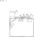
- Fig. 1 is a diagram illustrating a configuration of a humidity control device according to Embodiment 1 of the invention.
- the air-conditioning system of Embodiment 1 includes an outdoor unit 10a, an indoor unit 20, a humidity control device 30, and a controller 40.
- the outdoor unit 10a is connected to the indoor unit 20 and the humidity control device 30 with a liquid side main pipe 102, liquid side branch pipes 104, a gas side main pipe 103, and gas side branch pipes 105 such that a refrigerant can circulate through the pipes.
- the outdoor unit 10a, the indoor unit 20, and the humidity control device 30 are connected with a transmission line 101 for communication so as to allow transmission and reception of signals.
- the outdoor unit 10a is also connected to the controller 40 with the transmission line 101.
- each of the indoor unit 20 and the humidity control device 30 connected to the outdoor unit 10a there is only one of each of the indoor unit 20 and the humidity control device 30 connected to the outdoor unit 10a in Fig. 1 , there may be more than one of each of these devices.
- the number of indoor units 20 and the number of humidity control devices 30 to be connected to the outdoor unit 10a may be changed in accordance with the outdoor unit capacity, the required humidification amount, and the like (the same applies to the following description).
- Fig. 2 is a diagram showing components and the like constituting a refrigerant circuit in the air-conditioning system according to Embodiment 1 of the invention.
- the outdoor unit 10a includes, as components constituting the refrigerant circuit, a compressor 11, an outdoor heat exchanger 12, a four-way valve 13, and an accumulator 14.
- the compressor 11 of Embodiment 1 is a variable displacement compressor (fluid machinery) that is capable of varying the displacement using an inverter circuit in accordance with an instruction from outdoor unit control means 16.
- various types of compressors may be used as the compressor 11, such as a reciprocating type, a rotary type, a scroll type, and a screw type.
- the outdoor heat exchanger 12 exchanges heat between the refrigerant and air (outdoor air).
- the outdoor heat exchanger 12 serves as an evaporator during a heating operation so as to evaporate and gasify the refrigerant.
- the outdoor heat exchanger 12 serves as a condenser during a cooling operation so as to condense and liquefy the refrigerant.
- the four-way valve 13 serving as a flow switching device switches the flow of the refrigerant between a flow for a cooling operation and a flow for a heating operation in accordance with an instruction from the outdoor unit control means 16.
- the accumulator 14 is a tank that prevents the refrigerant in the form of a liquid (liquid refrigerant) from passing therethrough and thereby prevents the liquid refrigerant from flowing into the compressor 11.
- the outdoor unit 20 includes an indoor unit expansion valve 21 and an indoor unit heat exchanger 22.
- the indoor unit expansion valve (throttle device, flow control device) 21 serving as a first expansion device adjusts the pressure and the like of the refrigerant by changing the opening degree in accordance with an instruction from indoor unit control means 24.
- the valve opening degree can be minutely controlled using a stepping motor.
- the indoor unit heat exchanger 22 serving as a first indoor heat exchanger exchanges heat between the refrigerant and the air in the room (conditioned area, conditioned space), particularly for the purpose of temperature control.
- the indoor unit heat exchanger 22 serves as a condenser during a heating operation, and serves as an evaporator during a cooling operation.
- the humidity control device 30 includes a humidity control device expansion valve 31 and a humidity control device heat exchanger 32.
- the humidity control device expansion valve 31 serving as a second expansion device adjusts the pressure of the refrigerant by changing the opening degree in accordance with an instruction from humidity control device control means 36.
- the valve opening degree of the indoor unit expansion valve 21 can be minutely controlled.
- the humidity control device heat exchanger 32 serving as a second indoor heat exchanger exchanges heat between the refrigerant and the air in the room, particularly for the purpose of humidity control.
- the humidity control device heat exchanger 32 is designed to serve as an evaporator so as to perform dehumidification during a cooling operation.
- the refrigerant used in the refrigerant circuit may include, but is not limited to, natural refrigerants such as carbon dioxide, hydrocarbon, and helium, for example.
- the refrigerant used herein may further include refrigerants not containing chlorine, such as HFC410A and HFC407C, and fluorocarbon refrigerants that are used in existing products, such as R22 and R134a.
- the outdoor unit 10a is provided with, in addition to the components constituting the refrigerant circuit, outdoor air-sending means 15 that sends the air to the outdoor heat exchanger 12.
- the outdoor unit 10a is further provided with outdoor unit control means 16 that controls the components of the outdoor unit 10a in accordance with a control signal transmitted from the controller 40.
- the indoor unit 20 is provided with indoor unit air-sending means 23 that causes the air that has been introduced from the conditioned area to pass through the indoor unit heat exchanger 22 and sends the air to the conditioned area (humidity controlled space).
- the indoor unit 20 is further provided with indoor unit control means 24 that controls the components of the indoor unit 20 in accordance with a control signal transmitted from the controller 40.
- the humidity control device 30 is provided with humidity control device air-sending means 35 that introduces the air from the conditioned area through an air inlet 38, causes the air to pass through an air path in a main body 37, and sends the air into the conditioned area through an air outlet 39.
- the humidity control device 30 further include two water adsorption/desorption devices (first and second water adsorption/desorption devices) 33a and 33b that are capable of adsorbing water from the air passing therethrough and desorbing (releasing) water into the air passing therethrough.
- the humidity control device 30 further includes air flow switching means 34a and 34b that perform switching between air channels in the air path.
- the air flow switching means 34a on an upstream side close to the air inlet 38 is a first branch part, and the air flow switching means 34b on a downstream side close to the air outlet 39 is a second branch part.
- the humidity control device 30 is further provided with humidity control device control means 36 that controls the components of the humidity control device 30 in accordance with a control signal transmitted from the controller 40.
- the humidity control device 30 is constituted by including the main body 37, the water adsorption/desorption devices 33a and 33b, and the air flow switching means 34a and 34b, in addition to the components corresponding to those of the indoor unit 20.
- the configuration and the operations of the humidity control device 30 will be described below in greater detail.
- the outdoor air-sending means 15, the indoor unit air-sending means 23, and the humidity control device air-sending means 35 are configured such that the air volume can be adjusted and controlled, and such that the air volume can be set in accordance with the air conditions, for example.
- the air volume can be controlled by controlling the rotation speed.
- the air volume can be controlled by changing the power supply frequency using inverter control and thereby changing the rotation speed.
- a discharge pressure sensor 1a is provided on a discharge side of the compressor 11. Further, a suction pressure sensor 1b is provided on a suction side.
- a liquid pipe temperature sensor 2a and a gas pipe temperature sensor 2b are provided in each of the indoor unit 20 and the humidity control device 30.
- an outdoor air temperature sensor 2c is provided on an air inflow side of the outdoor heat exchanger 12.
- An inlet air temperature sensor 2d is provided on an air inlet side of the indoor unit heat exchanger 22 of the indoor unit 20.
- a temperature/humidity sensor 3 is provided on an air inlet 38 side of the humidity control device 30 (described below).
- the refrigerant that has been discharged from the compressor 11 of the outdoor unit 10a flows into the outdoor heat exchanger 12 via the four-way valve 13.
- the refrigerant is condensed and liquefied in the outdoor heat exchanger 12 through heat exchange with the air, and flows out of the outdoor unit 10a.
- the refrigerant that has flowed out therefrom flows through the liquid side main pipe 102, and is branched into the liquid side branch pipes 104 so as to flow into the indoor unit 20 and the humidity control device 30.
- the refrigerants that have flowed into the indoor unit 20 and the humidity control device 30 are subjected to pressure reduction in the indoor unit expansion valve 21 and the humidity control device expansion valve 32, respectively, and then flow into the indoor unit heat exchanger 22 and the humidity control device heat exchanger 32, respectively.
- the refrigerants are evaporated and gasified through heat exchange with the air in the indoor unit heat exchanger 22 and the humidity control device heat exchanger 32, respectively, and flow out of the indoor unit 20 and the humidity control device 30, respectively.
- the refrigerants that have flowed out therefrom flow through the gas side branch pipes 105 and the gas side main pipe 103, and flow into the outdoor unit 10a.
- the refrigerant that has flowed therein passes through the four-way valve 13 and the accumulator 14, and is suctioned again by the compressor 11.
- the flow for a heating operation is switched from the flow for a cooling operation by switching the four-way valve 13.
- the refrigerant that has been discharged from the compressor 11 flows out of the outdoor unit 10a through the four-way valve 13.
- the refrigerant that has flowed out therefrom flows through the gas side main pipe 103, and is branched into the gas side branch pipes 105 so as to flow into the indoor unit 20 and the humidity control device 30.
- the refrigerants that have flowed into the indoor unit 20 and the humidity control device 30 flow into the indoor unit heat exchanger 22 and the humidity control device heat exchanger 32, respectively.
- the refrigerants are condensed and liquefied through heat exchange with the air in the indoor unit heat exchanger 22 and the humidity control device heat exchanger 32. Then, the refrigerants are subjected to pressure reduction at the indoor unit expansion valve 21 and the humidity control device expansion valve 31, respectively, and then flow out of the indoor unit 20 and the humidity control device 30, respectively.
- the refrigerants that have flowed out from the indoor unit 20 and the humidity control device 30 flow through the liquid side branch pipes 104 and the liquid side main pipe 102, and flow into the outdoor unit 10a.
- the refrigerant that has flowed therein flows into the outdoor heat exchanger 12. In the heat exchanger 12, the refrigerant is evaporated and gasified through heat exchange with the air. Then, the refrigerant passes through the four-way valve 13 and the accumulator 14, and is suctioned again by the compressor 11.
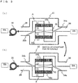
- Fig. 3 is a diagram illustrating operations of the humidity control device 30 according to Embodiment 1. The following describes a dehumidification operation performed by the humidity control device 30. In the following, a case in which a cooling operation is performed by the air-conditioning system will be described.
- the air channel A is a channel in which the air passes through the water adsorption/desorption device 33a, the humidity control device heat exchanger 32, and the water adsorption/desorption device 33b in this order.
- the air channel can be switched by operating the air flow switching means 34a and 34b, which may be formed of a damper, for example. Further, the switching time can be controlled by controlling rotation operations of a motor or the like that is used for switching the channels.
- the air channel switching means 34a is disposed upstream of the water adsorption/desorption devices 33a and 33b and the humidity control device heat exchanger 32 relative to the flow of the air.
- the air channel switching means 34b is disposed downstream of the water adsorption/desorption devices 33a and 33b and the humidity control device heat exchanger 32 relative to the flow of the air.
- the air that has passed through the humidity control device heat exchanger 32 passes through the water adsorption/desorption device 33b.
- the adsorbent further adsorbs water from the air so as to dehumidify the air.
- the air that has passed through the water adsorption/desorption device 33b passes through the humidity control device air-sending means 35, flows out from the air outlet 39, and is supplied as supply air SA into the room (conditioned space).
- the air channel B is a channel in which the air passes through the water adsorption/desorption device 33b, the humidity control device heat exchanger 32, and the water adsorption/desorption device 33a in this order.
- a return air RA is suctioned from the air inlet 38 and passes through the water adsorption/desorption device 33b.
- the adsorbent of the water adsorption/desorption device 33b releases water into the air through a desorption reaction, and humidifies the air passing therethrough.
- the air that has passed through the water adsorption/desorption device 33b passes through the humidity control device heat exchanger 32.
- the humidity control device heat exchanger 32 serving as an evaporator cools the air to its dew point temperature or below so as to dehumidify the air.
- the air that has passed through the humidity control device heat exchanger 32 passes through the water adsorption/desorption device 33a.
- the adsorbent In the water adsorption/desorption device 33a, the adsorbent further adsorbs water from the air so as to dehumidify the air.
- the air that has passed through the water adsorption/desorption device 33a passes through the humidity control device air-sending means 35, flows out from the air outlet 39, and is supplied as supply air SA into the room.
- each of the water adsorption/desorption device 33a and 33b of Embodiment 1 is a polygonal porous plate having a shape corresponding to a cross sectional shape of the air path so as to have a greater ventilation cross sectional area with respect to a cross sectional area of the air path of the device, and is configured such that the air passes therethrough in a thickness direction thereof.
- the porous plate used herein is prepared by applying to the surface thereof an adsorbent, such as zeolite, silica gel, and activate carbon, that has a characteristic of adsorbing water from the air with a relatively high humidity and releasing water into the air with a relatively low humidity, and then being subjected to a surface finishing treatment and impregnation.
- an adsorbent such as zeolite, silica gel, and activate carbon
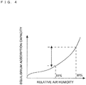
- Fig. 4 is a chart showing a relationship between the relative air humidity of the air and the equilibrium adsorption capacity.
- the amount of water (equilibrium adsorption capacity) which the adsorbent used in the water adsorption/desorption devices 33a and 33b can adsorb with respect to the relative air humidity is shown.
- the equilibrium adsorption capacity increases as the relative air humidity increases.
- adsorbent used in this embodiment, as mentioned above, use of an adsorbent having a great difference between the equilibrium adsorption capacity at a relative air humidity of 80% or greater and the equilibrium adsorption capacity at a relative air humidity in a range of 40% - 60% makes it possible to increase the water adsorption/desorption capacity of the water adsorption/desorption devices 33a and 33b.
- the flow velocity of the air passing through the water adsorption/desorption devices 33a and 33b also varies. Since the transfer rate of the water between the air and the adsorbent upon adsorption/desorption by the water adsorption/desorption devices 33a and 33b increases as the air flow velocity increases, the humidification/dehumidification capacity can be increased.
- the humidity control device air-sending means 35 is disposed on the most downstream side (the air outlet 39 side) in Fig. 3 , the humidity control device air-sending means 35 may be disposed on the most upstream side (the air inlet 38 side) as long as the target air volume can be obtained in the two air channels. Further, a plurality of humidity control device air-sending means 35 may be disposed on the upstream side and downstream side. As described herein, the arrangement position and the number of the humidity control device air-sending means 35 are not limited to those of this embodiment.
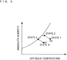
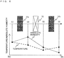
- Fig. 5 is a psychrometric chart illustrating a change in the state of the air during a dehumidification operation of the humidity control device 30. It is to be noted that States 1 through 4 representing the air states in Fig. 5 correspond to the air states at positions (1) through (4), respectively, in Fig. 3 . Further, Fig. 6 is a chart showing the temperature and the absolute humidity of the passing air in each of the states at predetermined positions in the humidity control device 30. It is to be noted that Fig. 6 shows the changes in the case of the air channel A. In the case of the air channel B, the positional relationship between the water adsorption/desorption device 33a and the position of the water adsorption/desorption device 33b is reversed.
- the air state during a dehumidification operation will be described in detail with reference to Figs. 4 through 6 .
- the above-described air channel A in the humidity control device 30, the return air RA (State 1) passes through the water adsorption/desorption device 33a.
- the return air RA that has been introduced from the room has a relative humidity in a range of 40% - 60% due to the indoor environment.
- the water adsorption/desorption device 33a releases water through a desorption reaction of the adsorbent in accordance with the water content, the air is humidified (the air becomes humidified air) (State 2).
- the humidified air has a lower temperature than and a higher relative humidity than the introduced air (the air in State 1).
- the absolute humidity is increased, the dew point temperature is increased, and therefore the air will be condensed more easily.
- the humidified air passes through the humidity control device heat exchanger 32 and is cooled to the dew temperature or below, the humidified air is dehumidified (the humidified air becomes dehumidified air) (State 3).
- the relative humidity of the dehumidified air is as high as about 70% - 90%. Therefore, the adsorbent of the water adsorption/desorption device 33b can adsorb water more easily.
- the dehumidified air passes through the water adsorption/desorption device 33b. At this point, water is adsorbed through an adsorption reaction in the adsorbent of the water adsorption/desorption device 33b, so that the air is further dehumidified.
- the dehumidified air is supplied into the room as supply air SA (State 4).
- the return air RA passes through the water adsorption/desorption device 33b.
- the return air RA that has been introduced from the room has a relative humidity in a range of 40% - 60% due to the indoor environment.
- the water adsorption/desorption device 33b releases water through a desorption reaction of the adsorbent in accordance with the water content, the air is humidified (the air becomes humidified air) (State 2).
- the humidified air has a lower temperature than and a higher relative humidity than the introduced air (the air in State 1).
- the absolute humidity is increased, the dew point temperature is increased, and therefore the air will be condensed more easily.
- the humidified air passes through the humidity control device heat exchanger 32 and is cooled to the dew temperature or below, the humidified air is dehumidified (the humidified air becomes dehumidified air) (State 3).
- the relative humidity of the dehumidified air is as high as about 70% - 90%. Therefore, the adsorbent of the water adsorption/desorption device 33a can adsorb water more easily.
- the dehumidified air passes through the water adsorption/desorption device 33a. At this point, water is adsorbed through an adsorption reaction in the adsorbent of the water adsorption/desorption device 33a, so that the air is further dehumidified.
- the dehumidified air is supplied into the room as supply air SA (State 4).
- the air channel switching means 34a and 34b are operated so as to perform switching between the air channels A and B.
- the adsorbent of the water adsorption/desorption device 33b which performed an adsorption reaction in the channel A will perform a desorption operation in the channel B.
- the adsorbent of the water adsorption/desorption device 33a which performed a desorption reaction in the channel A will perform an adsorption operation in the channel B. Accordingly, the adsorbents can continuously perform a dehumidification operation without reaching a state of equilibrium.
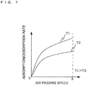
- Fig. 7 is a chart showing a relationship between the velocity of the air passing through the water adsorption/desorption devices 33a and 33b (the air passing velocity) and the adsorption/desorption speed.
- the adsorption/desorption speed of the adsorbents used in the water adsorption/desorption devices 33a and 33b varies in accordance with the air velocity (i.e., is dependent on the air velocity).
- the humidity control device air-sending means 35 controls and varies the air volume so as to increase the adsorption/desorption capacity of the water adsorption/desorption devices 33a and 33b.
- the adsorption/desorption speed is also dependent on the temperature. The higher the temperature is, the higher the adsorption/desorption speed becomes.
- Fig. 8 is a diagram showing a control relationship in the air-conditioning system.
- a controller 40 having means for inputting an operation instruction issued by a user controls the entire system.
- the pressure sensors 1a and 1b (the discharge pressure sensor 1a and the suction pressure sensor 1b), the temperature sensors 2a-2d (the liquid pipe temperature sensor 2a, the gas pipe temperature sensor 2b, the outdoor air temperature sensor 2c, and the inlet air temperature sensor 2d), and the temperature/humidity sensor 3 transmit signals indicating pressures, temperatures, and humidity that they have detected to the controller 40.
- the controller 40 transmits a control signal to the outdoor unit control means 16, the indoor unit control means 24, and the humidity control device control means 36 based on these pressures, temperatures, and humidity.
- the operations of the compressor 11, the indoor unit expansion valve 21, the humidity control device expansion valve 31, the outdoor air-sending means 15, the indoor air-sending means 23, the humidity control device air-sending means 35, the air flow switching means 34a and 34b, etc., can be controlled based on this control signal.
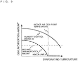
- Fig. 9 is a chart showing a relationship between the evaporating temperature of the refrigerant and the dehumidification amount of each of the indoor unit 20 and the humidity control device 30.
- the air-conditioning system of Embodiment 1 during a cooling operation, the air is humidified by the water adsorption/desorption device 33a or 33b, and then the humidified air passes through the humidity control device heat exchanger 32. Accordingly, the dew point temperature of the humidified air is increased. Therefore, as shown in Fig. 9 , it is possible to achieve the required dehumidification amount even when the evaporating temperature of the refrigerant is increased.
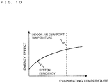
- Fig. 10 is a chart showing a relationship between the evaporating temperature of the refrigerant and the energy efficiency. As shown in Fig. 10 , the system efficiency increases as the evaporating temperature of the refrigerant increases. As mentioned above, since the air-conditioning system of Embodiment 1 can increase the evaporating temperatures of the refrigerants of the indoor unit 20 and the humidity control device 30, the system efficiency can be increased. This makes it possible to reduce the power consumption.
- the refrigerant circuit is formed by connecting the indoor unit 10a, the outdoor unit 20, and the humidity control device 30 to one another through pipes, there is no need to form an independent refrigerant circuit for humidity control by providing a compressor, for example. This makes it possible to reduce the weight of the entire system.
- the humidity control device 30 does not have a desorption heat source, it is possible to use the same pipe connection as in the case of indoor units of the related-art. Accordingly, it is easy to replace an air-conditioning system of the related art.
- the water adsorption/desorption devices 33a and 33b and the humidity control device heat exchanger 32 are arranged substantially in series in the direction in which the air flows in both the air channels A and B, and the humidity control device heat exchanger 32 is disposed between the water adsorption/desorption device 33a and the water adsorption/desorption device 33b.
- the water adsorption/desorption devices 33a and 33b and the humidity control device heat exchanger 32 can be stored in a small space in the main body 37 by arranging these devices such that the surfaces of the water adsorption/desorption devices 33a and 33b through which the air passes face the surfaces of the humidity control device heat exchanger 32 through which the air passes, respectively.
- the water adsorption/desorption devices 33a and 33b and the humidity control device heat exchanger 32 may not be accurately parallel to each other and may be slightly displaced in angle as long as the same advantages can be achieved.
- the dehumidification capacity can be changed in accordance with the environment by changing the balance between the installation number of the indoor units 20 and the humidity control devices 30.
- the water adsorption/desorption devices 33a and 33b using the adsorbents that have high equilibrium adsorption capacity at a high humidity range as shown in Fig. 4 are used, desorption can be performed utilizing only the difference between the water content of the water adsorption/desorption devices 33a and 33b and the equilibrium adsorption capacity which is dependent on the relative air humidity. Therefore, there is no need to provide any heating means. Accordingly, the size of the device can be reduced.
- the adsorption/desorption speed of the adsorbents of the water adsorption/desorption devices 33a and 33b are dependent not only on the air velocity but also on the temperature, the adsorption/desorption speed increases as the temperature increases. Therefore, in the case where there is a great difference between the temperature of the air upon desorption and the temperature of the air upon adsorption, there is a great difference between the adsorption and desorption speeds.
- the total amounts of water movement upon adsorption and desorption are balanced in accordance with one of the adsorption speed and the desorption speed having a lower rate.
- the difference between the temperature of the air upon adsorption and the temperature of the air upon desorption is smaller compared to the case where heating means is provided, and therefore the difference between the adsorption and desorption speeds is reduced. Accordingly, the adsorption speed and the desorption speed become close to equal to each other, which makes it possible to use the potential of the adsorbent with high efficiency.
- heating means that serves as the desorption heat source is not provided, the temperature difference between the water adsorption/desorption devices 33a and 33b is reduced even when the air channels are switched. Further, since the temperature difference with the passing air is reduced, the thermal resistance of the adsorbent generated due to the temperature difference between the adsorbents of the water adsorption/desorption devices 33a and 33b and the passing air is reduced. This makes it possible to perform dehumidification with high efficiency.
- the water adsorption/desorption devices 33a and 33b are fixed in the air path, and remain stationary without making any movement. Therefore, unlike a desiccant rotor that makes a rotational movement, the shapes of the water adsorption/desorption devices 33a and 33b are not limited. Accordingly, the ventilation areas of the water adsorption/desorption devices 33a and 33b can be formed to match the shape of the air path. Further, the pressure loss can be reduced by increasing the ventilation area and thereby reducing the air velocity. Also, the adsorption/desorption amount can be increased by increasing the contact area between the adsorbents of the water adsorption/desorption devices 33a and 33b and the air.
- the air inflow direction during an adsorption operation is opposite to that during a desorption operation, and the ventilation direction is reversed upon switching between adsorption and desorption operations. Accordingly, the humidification/dehumidification efficiency can be increased.
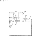
- Fig. 11 is a diagram illustrating a configuration of a humidity control device according to Embodiment 2 of the invention.
- an outdoor unit 10a and an indoor unit 20 are connected to each other with a liquid main pipe 102 and a gas main pipe 103 so as to constitute a refrigerant circuit.
- an outdoor unit 10b and a humidity control device 30 are connected to each other with pipes so as to constitute another refrigerant circuit.
- the outdoor unit 10a, the outdoor unit 10b, the indoor unit 20, the humidity control device 30, and a controller 40 are connected to each other with a transmission line 101 for communication, and can be controlled cooperatively as a system. Operations such as controlling dehumidification and the evaporating temperature of the refrigerant in the indoor unit 20 and the humidity control device 30 are the same as those described in Embodiment 1.
- the humidity control device 30 and the indoor unit 20 are separately connected to the outdoor units 10a and 10b, respectively. Therefore, the evaporating temperature of the refrigerant on the humidity control device 30 side and the evaporating temperature of the refrigerant on the indoor unit side can be changed and thus the evaporating temperature of the refrigerant can be set only for the purpose of temperature control in the indoor unit 20. Accordingly, the evaporating temperature can be further increased in the indoor unit 20, and the efficiency can be increased.
- Fig. 12 is a diagram illustrating a configuration of a humidity control device according to Embodiment 3 of the invention.
- the air-conditioning system of Embodiment 3 further includes an outdoor air treatment device 50.
- An outdoor unit 10a is connected to an indoor unit 20, a humidity control device 30, and the outdoor air treatment device 50 with a liquid main pipe 102, liquid branch pipes 104, a gas main pipe 103, and gas branch pipes 105 such that a refrigerant can circulate therethrough, and thus a refrigerant circuit is formed.
- they, including the outdoor air treatment device 50 are connected to each other with a transmission line 101 for communication so as to allow transmission and reception of signals.
- the outdoor air treatment device 50 includes an outdoor air treatment device expansion valve (third expansion device) 51, an outdoor air treatment device heat exchanger (third indoor heat exchanger) 52, a total heat exchanger 53, humidifying means 54, supply air sending means 55, exhaust air sending means 56, and outdoor air treatment device control means 57.
- the outdoor air treatment device expansion valve 51 is configured such that the valve opening degree thereof can be minutely controlled using a stepping motor, for example.
- the outdoor air treatment device heat exchanger 52 exchange heat between a refrigerant and outdoor air OA.
- the total heat exchanger 53 performs total heat exchange between the outdoor air OA and return air RA.
- the humidifying means 54 is configured to humidify the air that has passed through the outdoor air treatment device heat exchanger 52 and sends the humidified air into the room as supply air SA.
- the supply air sending means 55 is configured to form a flow of air by causing the outdoor air OA to pass through the total heat exchanger 53, the outdoor air treatment device heat exchanger 52, and the humidifying means 54 and to be supplied into the room as supply air SA.
- the exhaust air sending means 56 is configured to form a flow of air by causing the return air RA to pass through the total heat exchanger 53 and to be exhausted out of the room as exhaust air EA.
- the outdoor air treatment device control means 57 controls components of the outdoor air treatment device 50 in accordance with the control signal transmitted from the controller 40.
- the outdoor air OA passes through the total heat exchanger 53, the outdoor air treatment device indoor heat exchanger 52, and the humidifying means 54 in this order in the outdoor air treatment device 50, and is supplied into the room as supply air SA.
- the return air RA passes through the total heat exchanger 53 in the outdoor air treatment device 50, and is exhausted out of the room as exhaust air EA.
- Temperature control and humidity control operations of the outdoor unit 10a, the indoor unit 20, and the humidity control device 30 are the same as those described in Embodiment 1.
- the air-conditioning system of Embodiment 3 includes the outdoor air treatment device 50, and can perform a total heat exchange between the outdoor air OA and the return air RA using the total heat exchanger 53. Therefore, a workload to be generated by ventilation can be reduced, so that it is possible to reduce operations of driving the compressor 11.
- the outdoor air that has passed through the total heat exchanger 53 has a higher temperature and a higher humidity than the indoor air. Accordingly, the difference of the evaporating temperature of the refrigerant flowing through the outdoor air treatment device heat exchanger 52 from the temperature of the passing air is greater than the difference from the indoor air. Therefore, it is possible to perform heat treatment with higher efficiency.
- the outdoor air that has passed through the total heat exchanger 53 has a lower temperature and a lower humidity than the indoor air. Accordingly, the difference of the condensing temperature of the refrigerant flowing through the outdoor air treatment device heat exchanger 52 from the temperature of the passing air is greater than the difference from the indoor air. Therefore, it is possible to perform heat treatment with higher efficiency.
- the humidifying means 54 can humidify the passing air using a water supply type moisture permeable film, an ultrasonic humidifier, or the like.
- the outdoor air treatment device 50 is not provided with a compressor 11, all of the indoor unit 20, the humidity control device 30, and a device disposed above the ceiling in a position corresponding to the position of the outdoor air treatment device 50 do not need to be provide with a compressor 11, which makes it possible to reduce the size and weight.
- Fig. 13 is a diagram illustrating a configuration of a humidity control device according to Embodiment 4 of the invention.
- an outdoor air treatment device 50 is added to the configuration of Fig. 11 that is described in Embodiment 2.
- an outdoor unit 10a, an indoor unit 20, and the outdoor air treatment device 50 are connected to each other with a liquid main pipe 102, liquid branch pipes 104, a gas main pipe 103, and gas branch pipes 105 so as to constitute a refrigerant circuit.
- An outdoor unit 10b and a humidity control device 30 are connected to each other with a liquid main pipe 102 and a gas main pipe 103 so as to constitute another refrigerant circuit.
- the outdoor unit 10a, the outdoor unit 10b, the indoor unit 20, the humidity control device 30, a controller 40, and the outdoor air treatment device 50 are connected to each other with a transmission line 101 for communication, and can be controlled cooperatively as a system. Operations of controlling dehumidification and the evaporating temperature of the refrigerant in the indoor unit 20 and the humidity control device 30 are the same as those described in Embodiments 1 and 2.
- the humidity control device 30, and the outdoor air treatment device 50 and the indoor unit 20 are separately connected to the outdoor units 10a and 10b, respectively. Therefore, the evaporating temperature of the refrigerant on the humidity control device 30 side and the evaporating temperature of the refrigerant on the indoor unit side can be changed and thus the evaporating temperature of the refrigerant can be set only for the purpose of temperature control in the indoor unit 20. Accordingly, the evaporating temperature can be further increased in the indoor unit 20, and the efficiency can be increased.
- the outdoor unit 10b and the humidity control device 30 are connected to each other with pipes so as to constitute a refrigerant circuit in the above Embodiments 2 and 4, a humidity control device into which the outdoor unit 10b and the humidity control device 30 are integrated may be provided.
- the present invention further comprises the following aspects.
Description
- The present invention relates to a humidity control device configured to perform an indoor humidity control operation (hereinafter referred to as "humidity control"), and that is configured to perform an air conditioning operation.
- In an air-conditioning system of the related art, one or more outdoor units and one or more indoor units are connected to each other with pipes so as to constitute a refrigerant circuit in which a refrigerant circulates such that a vapor compression refrigeration cycle is performed.
- Indoor air conditioning may be performed by carrying out temperature control or by carrying out humidity control. There has been proposed a system that processes temperature control and humidity control separately so as to increase a refrigerant evaporating temperature in a refrigerant circuit of the temperature control side, and thereby reduce power consumption (see
Patent Literature 1, for example). - A humidity control device of this system has a refrigerant circuit, which is provided separately from that of an air-conditioning device, and serves as a ventilation device so as to perform humidity control with a high-efficiency refrigeration cycle using the outdoor air.
JP2010084970A - Patent Literature 1: Japanese Unexamined Patent Application Publication No.
2010-121912 Aspect 1,Fig. 1 ) - The humidity control device of
Patent Literature 1 serves as a ventilation device, and therefore is usually disposed above a ceiling. However, since the ventilation device includes its own refrigerant circuit, the weight of the device is increased. - Moreover, since the humidity control device serves as a ventilation device, the air volume is limited by the ventilation volume when compared with a typical indoor unit. Accordingly, the evaporating temperature needs to be lowered, resulting in increase of power consumption. This leads to reduction in energy efficiency in order to achieve the required dehumidification amount.
- The present invention has been made to overcome the above-described problem and an object thereof is to provide an air-conditioning system and the like that is capable of efficiently performing temperature control and humidity control.
- A humidity control device according to the independent claim is provided. The humidity control device according to the invention includes: at least one outdoor unit including a compressor, a flow switching device, and an outdoor heat exchanger; at least one indoor unit including a first expansion device and a first indoor heat exchanger; and at least one humidity control device including a second expansion device, a second indoor heat exchanger, and first and second water adsorption/desorption devices, in which the compressor, the flow switching device, the outdoor heat exchanger, the first expansion device, the first indoor heat exchanger, the second expansion device, and the second indoor heat exchanger are connected to each other with pipes so as to constitute a refrigerant circuit.
- According to the invention, in the humidity control device, the first and second water adsorption/desorption devices are provided. The second water adsorption/desorption is disposed upstream of the second indoor heat exchanger relative to the flow of air, and humidifies the air so as to increase a dew point temperature of the air that flows into the second indoor heat exchanger, for example. Thus, even if an evaporating temperature of a refrigerant is increased, it is possible to achieve the required dehumidification amount. Accordingly, the amount of dehumidification using, for example, a ventilation device can be reduced, so that it is possible to increase the energy efficiency by reducing power consumption, while maintaining comfort.
-
-
Fig. 1 is a diagram illustrating a configuration of humidity control device according toEmbodiment 1 of the invention. -
Fig. 2 is a diagram illustrating a configuration of a refrigerant circuit in the system according toEmbodiment 1 of the invention. -
Fig. 3 is a diagram illustrating a configuration of ahumidity control device 30 according toEmbodiment 1 of the invention. -
Fig. 4 is a chart showing a relationship between the relative humidity of air and the equilibrium adsorption capacity according toEmbodiment 1. -
Fig. 5 is a psychrometric chart illustrating a dehumidifying operation according toEmbodiment 1. -
Fig. 6 is a chart showing the temperature and the absolute humidity during the dehumidifying operation according toEmbodiment 1. -
Fig. 7 is a chart showing a relationship between the air velocity and the water adsorption/desorption speed of an adsorbent according toEmbodiment 1. -
Fig. 8 is a diagram illustrating a control relationship in the air-conditioning system according toEmbodiment 1 of the invention. -
Fig. 9 is a chart showing a relationship between the evaporating temperature and the dehumidification amount of each of anindoor unit 20 and ahumidity control device 30. -
Fig. 10 is a chart showing a relationship of the evaporating temperature and the energy efficiency of the air-conditioning system. -
Fig. 11 is a diagram illustrating a configuration of a humidity control device according toEmbodiment 2 of the invention. -
Fig. 12 is a diagram illustrating a configuration of a humidiy control device according toEmbodiment 3 of the invention. -
Fig. 13 is a diagram illustrating a configuration of humidity control device according toEmbodiment 4 of the invention. -
Fig. 1 is a diagram illustrating a configuration of a humidity control device according toEmbodiment 1 of the invention. The air-conditioning system of Embodiment 1 includes anoutdoor unit 10a, anindoor unit 20, ahumidity control device 30, and acontroller 40. Theoutdoor unit 10a is connected to theindoor unit 20 and thehumidity control device 30 with a liquid sidemain pipe 102, liquidside branch pipes 104, a gas sidemain pipe 103, and gasside branch pipes 105 such that a refrigerant can circulate through the pipes. In addition, theoutdoor unit 10a, theindoor unit 20, and thehumidity control device 30 are connected with atransmission line 101 for communication so as to allow transmission and reception of signals. Further, theoutdoor unit 10a is also connected to thecontroller 40 with thetransmission line 101. It should be noted that although there is only one of each of theindoor unit 20 and thehumidity control device 30 connected to theoutdoor unit 10a inFig. 1 , there may be more than one of each of these devices. For example, the number ofindoor units 20 and the number ofhumidity control devices 30 to be connected to theoutdoor unit 10a may be changed in accordance with the outdoor unit capacity, the required humidification amount, and the like (the same applies to the following description). -
Fig. 2 is a diagram showing components and the like constituting a refrigerant circuit in the air-conditioning system according toEmbodiment 1 of the invention. Theoutdoor unit 10a includes, as components constituting the refrigerant circuit, acompressor 11, anoutdoor heat exchanger 12, a four-way valve 13, and anaccumulator 14. Thecompressor 11 ofEmbodiment 1 is a variable displacement compressor (fluid machinery) that is capable of varying the displacement using an inverter circuit in accordance with an instruction from outdoor unit control means 16. For example, various types of compressors may be used as thecompressor 11, such as a reciprocating type, a rotary type, a scroll type, and a screw type. The outdoor heat exchanger 12 exchanges heat between the refrigerant and air (outdoor air). For example, theoutdoor heat exchanger 12 serves as an evaporator during a heating operation so as to evaporate and gasify the refrigerant. In addition, theoutdoor heat exchanger 12 serves as a condenser during a cooling operation so as to condense and liquefy the refrigerant. The four-way valve 13 serving as a flow switching device switches the flow of the refrigerant between a flow for a cooling operation and a flow for a heating operation in accordance with an instruction from the outdoor unit control means 16. Theaccumulator 14 is a tank that prevents the refrigerant in the form of a liquid (liquid refrigerant) from passing therethrough and thereby prevents the liquid refrigerant from flowing into thecompressor 11. - On the other hand, the
outdoor unit 20 includes an indoorunit expansion valve 21 and an indoorunit heat exchanger 22. The indoor unit expansion valve (throttle device, flow control device) 21 serving as a first expansion device adjusts the pressure and the like of the refrigerant by changing the opening degree in accordance with an instruction from indoor unit control means 24. In this embodiment, the valve opening degree can be minutely controlled using a stepping motor. The indoorunit heat exchanger 22 serving as a first indoor heat exchanger exchanges heat between the refrigerant and the air in the room (conditioned area, conditioned space), particularly for the purpose of temperature control. The indoorunit heat exchanger 22 serves as a condenser during a heating operation, and serves as an evaporator during a cooling operation. - The
humidity control device 30 includes a humidity controldevice expansion valve 31 and a humidity controldevice heat exchanger 32. The humidity controldevice expansion valve 31 serving as a second expansion device adjusts the pressure of the refrigerant by changing the opening degree in accordance with an instruction from humidity control device control means 36. In this embodiment, the valve opening degree of the indoorunit expansion valve 21 can be minutely controlled. The humidity controldevice heat exchanger 32 serving as a second indoor heat exchanger exchanges heat between the refrigerant and the air in the room, particularly for the purpose of humidity control. In this embodiment, the humidity controldevice heat exchanger 32 is designed to serve as an evaporator so as to perform dehumidification during a cooling operation. - The refrigerant used in the refrigerant circuit may include, but is not limited to, natural refrigerants such as carbon dioxide, hydrocarbon, and helium, for example. The refrigerant used herein may further include refrigerants not containing chlorine, such as HFC410A and HFC407C, and fluorocarbon refrigerants that are used in existing products, such as R22 and R134a.
- The
outdoor unit 10a is provided with, in addition to the components constituting the refrigerant circuit, outdoor air-sending means 15 that sends the air to theoutdoor heat exchanger 12. Theoutdoor unit 10a is further provided with outdoor unit control means 16 that controls the components of theoutdoor unit 10a in accordance with a control signal transmitted from thecontroller 40. - On the other hand, the
indoor unit 20 is provided with indoor unit air-sending means 23 that causes the air that has been introduced from the conditioned area to pass through the indoorunit heat exchanger 22 and sends the air to the conditioned area (humidity controlled space). Theindoor unit 20 is further provided with indoor unit control means 24 that controls the components of theindoor unit 20 in accordance with a control signal transmitted from thecontroller 40. - Further, the
humidity control device 30 is provided with humidity control device air-sending means 35 that introduces the air from the conditioned area through anair inlet 38, causes the air to pass through an air path in amain body 37, and sends the air into the conditioned area through anair outlet 39. Thehumidity control device 30 further include two water adsorption/desorption devices (first and second water adsorption/desorption devices) 33a and 33b that are capable of adsorbing water from the air passing therethrough and desorbing (releasing) water into the air passing therethrough. Thehumidity control device 30 further includes air flow switching means 34a and 34b that perform switching between air channels in the air path. The air flow switching means 34a on an upstream side close to theair inlet 38 is a first branch part, and the air flow switching means 34b on a downstream side close to theair outlet 39 is a second branch part. Thehumidity control device 30 is further provided with humidity control device control means 36 that controls the components of thehumidity control device 30 in accordance with a control signal transmitted from thecontroller 40. As can be seen from the above, thehumidity control device 30 is constituted by including themain body 37, the water adsorption/desorption devices indoor unit 20. The configuration and the operations of thehumidity control device 30 will be described below in greater detail. - In
Embodiment 1, the outdoor air-sendingmeans 15, the indoor unit air-sendingmeans 23, and the humidity control device air-sendingmeans 35 are configured such that the air volume can be adjusted and controlled, and such that the air volume can be set in accordance with the air conditions, for example. In the case where a DC motor is used as a motor for rotating the fan, the air volume can be controlled by controlling the rotation speed. On the other hand, in the case where an AC motor is used, the air volume can be controlled by changing the power supply frequency using inverter control and thereby changing the rotation speed. - A discharge pressure sensor 1a is provided on a discharge side of the
compressor 11. Further, a suction pressure sensor 1b is provided on a suction side. On the other hand, a liquidpipe temperature sensor 2a and a gaspipe temperature sensor 2b are provided in each of theindoor unit 20 and thehumidity control device 30. Further, an outdoor air temperature sensor 2c is provided on an air inflow side of theoutdoor heat exchanger 12. An inletair temperature sensor 2d is provided on an air inlet side of the indoorunit heat exchanger 22 of theindoor unit 20. Further, a temperature/humidity sensor 3 is provided on anair inlet 38 side of the humidity control device 30 (described below). - Next, a description will be given of a flow of the refrigerant in the refrigerant circuit during a cooling operation with reference to
Fig. 2 . The refrigerant that has been discharged from thecompressor 11 of theoutdoor unit 10a flows into theoutdoor heat exchanger 12 via the four-way valve 13. The refrigerant is condensed and liquefied in theoutdoor heat exchanger 12 through heat exchange with the air, and flows out of theoutdoor unit 10a. The refrigerant that has flowed out therefrom flows through the liquid sidemain pipe 102, and is branched into the liquidside branch pipes 104 so as to flow into theindoor unit 20 and thehumidity control device 30. The refrigerants that have flowed into theindoor unit 20 and thehumidity control device 30 are subjected to pressure reduction in the indoorunit expansion valve 21 and the humidity controldevice expansion valve 32, respectively, and then flow into the indoorunit heat exchanger 22 and the humidity controldevice heat exchanger 32, respectively. The refrigerants are evaporated and gasified through heat exchange with the air in the indoorunit heat exchanger 22 and the humidity controldevice heat exchanger 32, respectively, and flow out of theindoor unit 20 and thehumidity control device 30, respectively. The refrigerants that have flowed out therefrom flow through the gasside branch pipes 105 and the gas sidemain pipe 103, and flow into theoutdoor unit 10a. The refrigerant that has flowed therein passes through the four-way valve 13 and theaccumulator 14, and is suctioned again by thecompressor 11. - Further, a description will be given of a flow of the refrigerant in the refrigerant circuit during a heating operation with reference to
Fig. 2 . In this embodiment, the flow for a heating operation is switched from the flow for a cooling operation by switching the four-way valve 13. The refrigerant that has been discharged from thecompressor 11 flows out of theoutdoor unit 10a through the four-way valve 13. The refrigerant that has flowed out therefrom flows through the gas sidemain pipe 103, and is branched into the gasside branch pipes 105 so as to flow into theindoor unit 20 and thehumidity control device 30. The refrigerants that have flowed into theindoor unit 20 and thehumidity control device 30 flow into the indoorunit heat exchanger 22 and the humidity controldevice heat exchanger 32, respectively. The refrigerants are condensed and liquefied through heat exchange with the air in the indoorunit heat exchanger 22 and the humidity controldevice heat exchanger 32. Then, the refrigerants are subjected to pressure reduction at the indoorunit expansion valve 21 and the humidity controldevice expansion valve 31, respectively, and then flow out of theindoor unit 20 and thehumidity control device 30, respectively. The refrigerants that have flowed out from theindoor unit 20 and thehumidity control device 30 flow through the liquidside branch pipes 104 and the liquid sidemain pipe 102, and flow into theoutdoor unit 10a. The refrigerant that has flowed therein flows into theoutdoor heat exchanger 12. In theheat exchanger 12, the refrigerant is evaporated and gasified through heat exchange with the air. Then, the refrigerant passes through the four-way valve 13 and theaccumulator 14, and is suctioned again by thecompressor 11. -
Fig. 3 is a diagram illustrating operations of thehumidity control device 30 according toEmbodiment 1. The following describes a dehumidification operation performed by thehumidity control device 30. In the following, a case in which a cooling operation is performed by the air-conditioning system will be described. - First, a description will be given of an operation in an air channel A with reference to
Fig. 3(a) . The air channel A is a channel in which the air passes through the water adsorption/desorption device 33a, the humidity controldevice heat exchanger 32, and the water adsorption/desorption device 33b in this order. The air channel can be switched by operating the air flow switching means 34a and 34b, which may be formed of a damper, for example. Further, the switching time can be controlled by controlling rotation operations of a motor or the like that is used for switching the channels. The air channel switching means 34a is disposed upstream of the water adsorption/desorption devices device heat exchanger 32 relative to the flow of the air. On the other hand, the air channel switching means 34b is disposed downstream of the water adsorption/desorption devices device heat exchanger 32 relative to the flow of the air. - When the humidity control device air-sending
means 35 is driven, return air RA is suctioned (introduced) from theair inlet 38, and passes through the water adsorption/desorption device 33a in themain body 37. At this point, the adsorbent of the water adsorption/desorption device 33a releases water into the air through a desorption reaction, and humidifies the air passing therethrough. The air that has passed through the water adsorption/desorption device 33a passes through the humidity controldevice heat exchanger 32. At this point, the humidity controldevice heat exchanger 32 serving as an evaporator cools the air to its dew point temperature or below so as to dehumidify the air. The air that has passed through the humidity controldevice heat exchanger 32 passes through the water adsorption/desorption device 33b. In the water adsorption/desorption device 33b, the adsorbent further adsorbs water from the air so as to dehumidify the air. The air that has passed through the water adsorption/desorption device 33b passes through the humidity control device air-sendingmeans 35, flows out from theair outlet 39, and is supplied as supply air SA into the room (conditioned space). - Next, a description will be given of an operation in an air channel B with reference to
Fig. 3(b) . The air channel B is a channel in which the air passes through the water adsorption/desorption device 33b, the humidity controldevice heat exchanger 32, and the water adsorption/desorption device 33a in this order. - When the humidity control device air-sending
means 35 is driven, a return air RA is suctioned from theair inlet 38 and passes through the water adsorption/desorption device 33b. At this point, the adsorbent of the water adsorption/desorption device 33b releases water into the air through a desorption reaction, and humidifies the air passing therethrough. The air that has passed through the water adsorption/desorption device 33b passes through the humidity controldevice heat exchanger 32. At this point, the humidity controldevice heat exchanger 32 serving as an evaporator cools the air to its dew point temperature or below so as to dehumidify the air. The air that has passed through the humidity controldevice heat exchanger 32 passes through the water adsorption/desorption device 33a. In the water adsorption/desorption device 33a, the adsorbent further adsorbs water from the air so as to dehumidify the air. The air that has passed through the water adsorption/desorption device 33a passes through the humidity control device air-sendingmeans 35, flows out from theair outlet 39, and is supplied as supply air SA into the room. - It is to be noted that each of the water adsorption/
desorption device Embodiment 1 is a polygonal porous plate having a shape corresponding to a cross sectional shape of the air path so as to have a greater ventilation cross sectional area with respect to a cross sectional area of the air path of the device, and is configured such that the air passes therethrough in a thickness direction thereof. Further, the porous plate used herein is prepared by applying to the surface thereof an adsorbent, such as zeolite, silica gel, and activate carbon, that has a characteristic of adsorbing water from the air with a relatively high humidity and releasing water into the air with a relatively low humidity, and then being subjected to a surface finishing treatment and impregnation. Although the water adsorption/desorption devices -
Fig. 4 is a chart showing a relationship between the relative air humidity of the air and the equilibrium adsorption capacity. InFig. 4 , the amount of water (equilibrium adsorption capacity) which the adsorbent used in the water adsorption/desorption devices desorption devices - Further, if the air volume of the humidity control device air-sending
means 35 varies, the flow velocity of the air passing through the water adsorption/desorption devices desorption devices - The humidity control device air-sending
means 35 is disposed on the most downstream side (theair outlet 39 side) inFig. 3 , the humidity control device air-sendingmeans 35 may be disposed on the most upstream side (theair inlet 38 side) as long as the target air volume can be obtained in the two air channels. Further, a plurality of humidity control device air-sendingmeans 35 may be disposed on the upstream side and downstream side. As described herein, the arrangement position and the number of the humidity control device air-sendingmeans 35 are not limited to those of this embodiment. -
Fig. 5 is a psychrometric chart illustrating a change in the state of the air during a dehumidification operation of thehumidity control device 30. It is to be noted thatStates 1 through 4 representing the air states inFig. 5 correspond to the air states at positions (1) through (4), respectively, inFig. 3 . Further,Fig. 6 is a chart showing the temperature and the absolute humidity of the passing air in each of the states at predetermined positions in thehumidity control device 30. It is to be noted thatFig. 6 shows the changes in the case of the air channel A. In the case of the air channel B, the positional relationship between the water adsorption/desorption device 33a and the position of the water adsorption/desorption device 33b is reversed. - Next, the air state during a dehumidification operation will be described in detail with reference to
Figs. 4 through 6 . The above-described air channel A in thehumidity control device 30, the return air RA (State 1) passes through the water adsorption/desorption device 33a. In many cases, the return air RA that has been introduced from the room has a relative humidity in a range of 40% - 60% due to the indoor environment. As described above, since the water adsorption/desorption device 33a releases water through a desorption reaction of the adsorbent in accordance with the water content, the air is humidified (the air becomes humidified air) (State 2). At this point, the humidified air has a lower temperature than and a higher relative humidity than the introduced air (the air in State 1). Further, since the absolute humidity is increased, the dew point temperature is increased, and therefore the air will be condensed more easily. - When the humidified air passes through the humidity control
device heat exchanger 32 and is cooled to the dew temperature or below, the humidified air is dehumidified (the humidified air becomes dehumidified air) (State 3). At this point, the relative humidity of the dehumidified air is as high as about 70% - 90%. Therefore, the adsorbent of the water adsorption/desorption device 33b can adsorb water more easily. Then, the dehumidified air passes through the water adsorption/desorption device 33b. At this point, water is adsorbed through an adsorption reaction in the adsorbent of the water adsorption/desorption device 33b, so that the air is further dehumidified. The dehumidified air is supplied into the room as supply air SA (State 4). - Next, a description will be given of the air channel B. In the air channel B, the return air RA (State 1) passes through the water adsorption/
desorption device 33b. In many cases, the return air RA that has been introduced from the room has a relative humidity in a range of 40% - 60% due to the indoor environment. As described above, since the water adsorption/desorption device 33b releases water through a desorption reaction of the adsorbent in accordance with the water content, the air is humidified (the air becomes humidified air) (State 2). At this point, the humidified air has a lower temperature than and a higher relative humidity than the introduced air (the air in State 1). Further, since the absolute humidity is increased, the dew point temperature is increased, and therefore the air will be condensed more easily. - When the humidified air passes through the humidity control
device heat exchanger 32 and is cooled to the dew temperature or below, the humidified air is dehumidified (the humidified air becomes dehumidified air) (State 3). At this point, the relative humidity of the dehumidified air is as high as about 70% - 90%. Therefore, the adsorbent of the water adsorption/desorption device 33a can adsorb water more easily. Then, the dehumidified air passes through the water adsorption/desorption device 33a. At this point, water is adsorbed through an adsorption reaction in the adsorbent of the water adsorption/desorption device 33a, so that the air is further dehumidified. The dehumidified air is supplied into the room as supply air SA (State 4). - Then, the air channel switching means 34a and 34b are operated so as to perform switching between the air channels A and B. Thus, the adsorbent of the water adsorption/
desorption device 33b which performed an adsorption reaction in the channel A will perform a desorption operation in the channel B. Conversely, the adsorbent of the water adsorption/desorption device 33a which performed a desorption reaction in the channel A will perform an adsorption operation in the channel B. Accordingly, the adsorbents can continuously perform a dehumidification operation without reaching a state of equilibrium. -
Fig. 7 is a chart showing a relationship between the velocity of the air passing through the water adsorption/desorption devices desorption devices means 35 controls and varies the air volume so as to increase the adsorption/desorption capacity of the water adsorption/desorption devices Fig. 7 , the adsorption/desorption speed is also dependent on the temperature. The higher the temperature is, the higher the adsorption/desorption speed becomes. -
Fig. 8 is a diagram showing a control relationship in the air-conditioning system. InEmbodiment 1, acontroller 40 having means for inputting an operation instruction issued by a user controls the entire system. The pressure sensors 1a and 1b (the discharge pressure sensor 1a and the suction pressure sensor 1b), thetemperature sensors 2a-2d (the liquidpipe temperature sensor 2a, the gaspipe temperature sensor 2b, the outdoor air temperature sensor 2c, and the inletair temperature sensor 2d), and the temperature/humidity sensor 3 transmit signals indicating pressures, temperatures, and humidity that they have detected to thecontroller 40. Thecontroller 40 transmits a control signal to the outdoor unit control means 16, the indoor unit control means 24, and the humidity control device control means 36 based on these pressures, temperatures, and humidity. The operations of thecompressor 11, the indoorunit expansion valve 21, the humidity controldevice expansion valve 31, the outdoor air-sendingmeans 15, the indoor air-sendingmeans 23, the humidity control device air-sendingmeans 35, the air flow switching means 34a and 34b, etc., can be controlled based on this control signal. -
Fig. 9 is a chart showing a relationship between the evaporating temperature of the refrigerant and the dehumidification amount of each of theindoor unit 20 and thehumidity control device 30. As mentioned above, in the air-conditioning system ofEmbodiment 1, during a cooling operation, the air is humidified by the water adsorption/desorption device device heat exchanger 32. Accordingly, the dew point temperature of the humidified air is increased. Therefore, as shown inFig. 9 , it is possible to achieve the required dehumidification amount even when the evaporating temperature of the refrigerant is increased. -
Fig. 10 is a chart showing a relationship between the evaporating temperature of the refrigerant and the energy efficiency. As shown inFig. 10 , the system efficiency increases as the evaporating temperature of the refrigerant increases. As mentioned above, since the air-conditioning system ofEmbodiment 1 can increase the evaporating temperatures of the refrigerants of theindoor unit 20 and thehumidity control device 30, the system efficiency can be increased. This makes it possible to reduce the power consumption. - Further, since the refrigerant circuit is formed by connecting the
indoor unit 10a, theoutdoor unit 20, and thehumidity control device 30 to one another through pipes, there is no need to form an independent refrigerant circuit for humidity control by providing a compressor, for example. This makes it possible to reduce the weight of the entire system. - Further, since the
humidity control device 30 does not have a desorption heat source, it is possible to use the same pipe connection as in the case of indoor units of the related-art. Accordingly, it is easy to replace an air-conditioning system of the related art. - Further, the water adsorption/
desorption devices device heat exchanger 32 are arranged substantially in series in the direction in which the air flows in both the air channels A and B, and the humidity controldevice heat exchanger 32 is disposed between the water adsorption/desorption device 33a and the water adsorption/desorption device 33b. The water adsorption/desorption devices device heat exchanger 32 can be stored in a small space in themain body 37 by arranging these devices such that the surfaces of the water adsorption/desorption devices device heat exchanger 32 through which the air passes, respectively. This makes it possible to reduce the size of thedehumidification device 30. With regard to the expression "facing" as used herein, the water adsorption/desorption devices device heat exchanger 32 may not be accurately parallel to each other and may be slightly displaced in angle as long as the same advantages can be achieved. - In the case where a plurality of
indoor units 20 are connected to theoutdoor unit 10a, the dehumidification capacity can be changed in accordance with the environment by changing the balance between the installation number of theindoor units 20 and thehumidity control devices 30. - Further, since the water adsorption/
desorption devices Fig. 4 are used, desorption can be performed utilizing only the difference between the water content of the water adsorption/desorption devices - In this case, if an adsorbent having a high equilibrium adsorption capacity particularly at a relative air humidity of 80% or higher is used, as mentioned above, humidification of the air can be performed without providing any special heating means that serves as the desorption heat source. This eliminates the need for processing the heat amount using heating means. Thus, the humidity control
device heat exchanger 32 only performs heat treatment on the return air RA, so that energy savings can be achieved. - Further, as shown in
Fig. 7 , since the adsorption/desorption speed of the adsorbents of the water adsorption/desorption devices dehumidification device 30 of the system ofEmbodiment 1, the difference between the temperature of the air upon adsorption and the temperature of the air upon desorption is smaller compared to the case where heating means is provided, and therefore the difference between the adsorption and desorption speeds is reduced. Accordingly, the adsorption speed and the desorption speed become close to equal to each other, which makes it possible to use the potential of the adsorbent with high efficiency. - Further, since heating means that serves as the desorption heat source is not provided, the temperature difference between the water adsorption/
desorption devices desorption devices - Further, the water adsorption/
desorption devices desorption devices desorption devices desorption devices - Further, in the water adsorption/
desorption devices -
Fig. 11 is a diagram illustrating a configuration of a humidity control device according toEmbodiment 2 of the invention. In this embodiment, anoutdoor unit 10a and anindoor unit 20 are connected to each other with a liquidmain pipe 102 and a gasmain pipe 103 so as to constitute a refrigerant circuit. Similarly, anoutdoor unit 10b and ahumidity control device 30 are connected to each other with pipes so as to constitute another refrigerant circuit. - In this embodiment, the
outdoor unit 10a, theoutdoor unit 10b, theindoor unit 20, thehumidity control device 30, and acontroller 40 are connected to each other with atransmission line 101 for communication, and can be controlled cooperatively as a system. Operations such as controlling dehumidification and the evaporating temperature of the refrigerant in theindoor unit 20 and thehumidity control device 30 are the same as those described inEmbodiment 1. - As described above, in the air-conditioning system of
Embodiment 2, thehumidity control device 30 and theindoor unit 20 are separately connected to theoutdoor units humidity control device 30 side and the evaporating temperature of the refrigerant on the indoor unit side can be changed and thus the evaporating temperature of the refrigerant can be set only for the purpose of temperature control in theindoor unit 20. Accordingly, the evaporating temperature can be further increased in theindoor unit 20, and the efficiency can be increased. -
Fig. 12 is a diagram illustrating a configuration of a humidity control device according toEmbodiment 3 of the invention. The air-conditioning system ofEmbodiment 3 further includes an outdoorair treatment device 50. Anoutdoor unit 10a is connected to anindoor unit 20, ahumidity control device 30, and the outdoorair treatment device 50 with a liquidmain pipe 102,liquid branch pipes 104, a gasmain pipe 103, andgas branch pipes 105 such that a refrigerant can circulate therethrough, and thus a refrigerant circuit is formed. In addition, they, including the outdoorair treatment device 50, are connected to each other with atransmission line 101 for communication so as to allow transmission and reception of signals. - The outdoor
air treatment device 50 includes an outdoor air treatment device expansion valve (third expansion device) 51, an outdoor air treatment device heat exchanger (third indoor heat exchanger) 52, atotal heat exchanger 53, humidifying means 54, supply air sending means 55, exhaust air sending means 56, and outdoor air treatment device control means 57. - Similar to the indoor
unit expansion valve 21, the outdoor air treatmentdevice expansion valve 51 is configured such that the valve opening degree thereof can be minutely controlled using a stepping motor, for example. The outdoor air treatmentdevice heat exchanger 52 exchange heat between a refrigerant and outdoor air OA. Thetotal heat exchanger 53 performs total heat exchange between the outdoor air OA and return air RA. The humidifying means 54 is configured to humidify the air that has passed through the outdoor air treatmentdevice heat exchanger 52 and sends the humidified air into the room as supply air SA. - The supply air sending means 55 is configured to form a flow of air by causing the outdoor air OA to pass through the
total heat exchanger 53, the outdoor air treatmentdevice heat exchanger 52, and the humidifying means 54 and to be supplied into the room as supply air SA. The exhaust air sending means 56 is configured to form a flow of air by causing the return air RA to pass through thetotal heat exchanger 53 and to be exhausted out of the room as exhaust air EA. The outdoor air treatment device control means 57 controls components of the outdoorair treatment device 50 in accordance with the control signal transmitted from thecontroller 40. - In this embodiment, the outdoor air OA passes through the
total heat exchanger 53, the outdoor air treatment deviceindoor heat exchanger 52, and the humidifying means 54 in this order in the outdoorair treatment device 50, and is supplied into the room as supply air SA. - On the other hand, the return air RA passes through the
total heat exchanger 53 in the outdoorair treatment device 50, and is exhausted out of the room as exhaust air EA. - Temperature control and humidity control operations of the
outdoor unit 10a, theindoor unit 20, and thehumidity control device 30 are the same as those described inEmbodiment 1. - As described above, the air-conditioning system of
Embodiment 3 includes the outdoorair treatment device 50, and can perform a total heat exchange between the outdoor air OA and the return air RA using thetotal heat exchanger 53. Therefore, a workload to be generated by ventilation can be reduced, so that it is possible to reduce operations of driving thecompressor 11. - Further, in the case where the outdoor air has a higher temperature and a higher humidity than the indoor air (assuming that the
outdoor unit 10a performs a cooling operation), the outdoor air that has passed through thetotal heat exchanger 53 has a higher temperature and a higher humidity than the indoor air. Accordingly, the difference of the evaporating temperature of the refrigerant flowing through the outdoor air treatmentdevice heat exchanger 52 from the temperature of the passing air is greater than the difference from the indoor air. Therefore, it is possible to perform heat treatment with higher efficiency. - Further, in the case where the outdoor air has a lower temperature and a lower humidity than the indoor air (assuming that the
outdoor unit 10a performs a heating operation), the outdoor air that has passed through thetotal heat exchanger 53 has a lower temperature and a lower humidity than the indoor air. Accordingly, the difference of the condensing temperature of the refrigerant flowing through the outdoor air treatmentdevice heat exchanger 52 from the temperature of the passing air is greater than the difference from the indoor air. Therefore, it is possible to perform heat treatment with higher efficiency. - In the case of performing a heating and humidification operation during winter, it is possible to humidify the room with use of the humidifying means 54. The humidifying means 54 can humidify the passing air using a water supply type moisture permeable film, an ultrasonic humidifier, or the like.
- Since the outdoor
air treatment device 50 is not provided with acompressor 11, all of theindoor unit 20, thehumidity control device 30, and a device disposed above the ceiling in a position corresponding to the position of the outdoorair treatment device 50 do not need to be provide with acompressor 11, which makes it possible to reduce the size and weight. -
Fig. 13 is a diagram illustrating a configuration of a humidity control device according toEmbodiment 4 of the invention. InFig. 13 , an outdoorair treatment device 50 is added to the configuration ofFig. 11 that is described inEmbodiment 2. In this embodiment, anoutdoor unit 10a, anindoor unit 20, and the outdoorair treatment device 50 are connected to each other with a liquidmain pipe 102,liquid branch pipes 104, a gasmain pipe 103, andgas branch pipes 105 so as to constitute a refrigerant circuit. Anoutdoor unit 10b and ahumidity control device 30 are connected to each other with a liquidmain pipe 102 and a gasmain pipe 103 so as to constitute another refrigerant circuit. - In this embodiment, the
outdoor unit 10a, theoutdoor unit 10b, theindoor unit 20, thehumidity control device 30, acontroller 40, and the outdoorair treatment device 50 are connected to each other with atransmission line 101 for communication, and can be controlled cooperatively as a system. Operations of controlling dehumidification and the evaporating temperature of the refrigerant in theindoor unit 20 and thehumidity control device 30 are the same as those described inEmbodiments - As described above, in the air-conditioning system of
Embodiment 4, thehumidity control device 30, and the outdoorair treatment device 50 and theindoor unit 20 are separately connected to theoutdoor units humidity control device 30 side and the evaporating temperature of the refrigerant on the indoor unit side can be changed and thus the evaporating temperature of the refrigerant can be set only for the purpose of temperature control in theindoor unit 20. Accordingly, the evaporating temperature can be further increased in theindoor unit 20, and the efficiency can be increased. - Although the
outdoor unit 10b and thehumidity control device 30 are connected to each other with pipes so as to constitute a refrigerant circuit in the above Embodiments 2 and 4, a humidity control device into which theoutdoor unit 10b and thehumidity control device 30 are integrated may be provided. - The present invention further comprises the following aspects.
- [Aspect 1] An air-conditioning system comprising:
- at least one outdoor unit including a compressor, a flow switching device, and an outdoor heat exchanger;
- at least one indoor unit including a first expansion device and a first indoor heat exchanger; and
- at least one humidity control device including a second expansion device, a second indoor heat exchanger, and first and second water adsorption/desorption devices,
- wherein the compressor, the flow switching device, the outdoor heat exchanger, the first expansion device, the first indoor heat exchanger, the second expansion device, and the second indoor heat exchanger are connected to each other with pipes so as to constitute a refrigerant circuit.
- [Aspect 2] The air-conditioning system of
aspect 1, further comprising
at least one outdoor air treatment device including a third expansion device and a third indoor heat exchanger,
wherein the third expansion device and the third indoor heat exchanger are further connected with the pipes so as to constitute the refrigerant circuit. - [Aspect 3] An air-conditioning system comprising:
- at least one first outdoor unit including a first compressor, a first flow switching device, and a first outdoor heat exchanger;
- at least one second outdoor unit including a second compressor, a second flow switching device, and a second outdoor heat exchanger;
- at least one indoor unit including a first expansion device and a first indoor heat exchanger; and
- at least one humidity control device including a second expansion device, a second indoor heat exchanger, and a water adsorption/desorption device,
- wherein the first compressor, the first flow switching device, the first outdoor heat exchanger, the first expansion device, and the first indoor heat exchanger are connected to each other with pipes so as to constitute a first refrigerant circuit, and
- wherein the second compressor, the second flow switching device, the second outdoor heat exchanger, the second expansion device, and the second indoor heat exchanger are connected to each other with pipes so as to constitute a second refrigerant circuit.
- [Aspect 4] The air-conditioning system of
aspect 3, further comprising
at least one outdoor air treatment device including a third expansion device and a third indoor heat exchanger,
wherein the third expansion device and the third indoor heat exchanger are further connected with the pipes so as to constitute the first refrigerant circuit. - [Aspect 5] The air-conditioning system of any one of
aspects 1 to 4,
wherein, in the humidity control device,
the first and second water adsorption/desorption devices are disposed in an air path providing communication between an air inlet through which air flows in from a humidity controlled space and an air outlet through which air flows out into the humidity controlled space, the first and second water adsorption/desorption devices each including an adsorbent whose equilibrium adsorption capacity with respect to air having a relative humidity in a range of 40% through 100% increase substantially linearly with an increase in the relative humidity, the first and second water adsorption/desorption devices being configured to release water into air having a relatively low humidity and adsorb water from air having a relatively high humidity,
the second indoor heat exchanger is disposed between the first water adsorption/desorption device and the second water adsorption/desorption device in the air path, and
the humidity control device further includes a switching device that switches between a channel in which the air that has flowed in through the air inlet is caused to pass through the first water adsorption/desorption device, the second indoor heat exchanger, and the second water adsorption/desorption device in this order, and a channel in which the air that has flowed in through the air inlet is caused to pass through the second water adsorption/desorption device, the second indoor heat exchanger, and the first water adsorption/desorption device in this order. - [Aspect 6] The air-conditioning system of any one of
aspects 1 to 5, wherein the first water adsorption/desorption device and the second water adsorption/desorption device are fixed and remain stationary in an air path providing communication between an air inlet through which air flows in from a humidity controlled space and an air outlet through which air flows out into the humidity controlled space. - [Aspect 7] The air-conditioning system of any one of
aspects 1 to 6, wherein the first water adsorption/desorption device and the second water adsorption/desorption device are ventilation bodies each having a large number of small through holes. - [Aspect 8] The air-conditioning system of any one of
aspects 1 to 7,
wherein the second indoor heat exchanger is disposed between the first water adsorption/desorption device and the second water adsorption/desorption device in an air path providing communication between an air inlet through which air flows in from a humidity controlled space and an air outlet through which air flows out into the humidity controlled space, and
wherein the first water adsorption/desorption device and the second water adsorption/desorption device are arranged such that air passage surfaces thereof face air passage surfaces of the second indoor heat exchanger, respectively. - [Aspect 9] The air-conditioning system of any one of
aspects 1 to 7,
wherein the second indoor heat exchanger is disposed between the first water adsorption/desorption device and the second water adsorption/desorption device in an air path providing communication between an air inlet through which air flows in from a humidity controlled space and an air outlet through which air flows out into the humidity controlled space, and
wherein a direction in which the air that passes through the first water adsorption/desorption device, the second indoor heat exchanger, and the second water adsorption/desorption device is reversed by switching air channels in the air path. - [Aspect 10] The air-conditioning system of any one of
aspects 5 to 9, wherein the switching device includes
a first branch part that is disposed upstream of the first water adsorption/desorption device and the second water adsorption/desorption device, and divides the air path into two branches; and
a second branch part that is disposed downstream of the first water adsorption/desorption device and the second water adsorption/desorption device, and divides the air path into two branches. - [Aspect 11] A humidity control device comprising:
- a compressor;
- a condenser;
- an expansion device;
- first and second water adsorption/desorption devices that are disposed in an air path providing communication between an air inlet through which air flows in from a humidity controlled space and an air outlet through which air flows out into the humidity controlled space, the first and second water adsorption/desorption devices each including an adsorbent whose equilibrium adsorption capacity with respect to air having a relative humidity in a range of 40% through 100% increases substantially linearly with an increase in the relative humidity, the first and second water adsorption/desorption devices being configured to release water into air having a relatively low humidity and adsorb water from air having a relatively high humidity;
- an evaporator disposed between the first water adsorption/desorption device and the second water adsorption/desorption device in the air path; and
- a switching device that switches between a channel in which the air that has flowed in through the air inlet is caused to pass through the first water adsorption/desorption device, the evaporator, and the second water adsorption/desorption device in this order, and a channel in which the air that has flowed in through the air inlet is caused to pass through the second water adsorption/desorption device, the evaporator, and the first water adsorption/desorption device in this order.
- 1a discharge pressure sensor; 1b suction pressure sensor; 2a liquid pipe temperature sensor; 2b gas pipe temperature sensor; 2c outdoor air temperature sensor; 2d inlet air temperature sensor; 3 temperature/humidity sensor; 10a, 10b outdoor unit; 11 compressor; 12 outdoor heat exchanger; 13 four-way valve; 14 accumulator; 15 outdoor unit air-sending means; 16 outdoor unit control means; 20 indoor unit; 21 indoor unit expansion valve; 22 indoor unit heat exchanger; 23 indoor unit air-sending means; 24 indoor unit control means; 30 humidity control device; 31 humidity control device expansion valve; 32 humidity control device heat exchanger; 33a, 33b water adsorption/desorption device; 34a, 34b air flow switching means; 35 humidity control device air-sending means; 36 humidity control device control means; 37 main body; 38 air inlet; 39 air outlet; 40 controller; 50 outdoor air treatment device; 51 outdoor air treatment device expansion valve; 52 outdoor air treatment device heat exchanger; 53 total heat exchanger; 54 humidifying means; 55 supply air sending means; 56 exhaust air sending means; 57 outdoor air treatment device control means; 101 transmission line; 102 liquid side main pipe; 103 gas side main pipe; 104 liquid side branch pipe; 105 gas side branch pipe; OA outdoor air; RA return air; SA supply air; and EA exhaust air.
Claims (1)
- A humidity control device (30) for an air-conditioning system including an indoor unit that has an indoor heat exchanger and an indoor unit expansion valve, the humidity control device (30) comprising:a compressor (11);a condenser;an expansion device;first and second water adsorption/desorption devices (33a, 33b) that are disposed in an air path providing communication between an air inlet through which air flows in from a humidity controlled space and an air outlet through which air flows out into the humidity controlled space, the first and second water adsorption/desorption devices (33a, 33b) each including an adsorbent whose equilibrium adsorption capacity with respect to air having a relative humidity in a range of 40% through 100% increases substantially linearly with an increase in the relative humidity, the first and second water adsorption/desorption devices (33a, 33b) being configured to release water into air having a relatively low humidity and adsorb water from air having a relatively high humidity;an evaporator disposed between the first water adsorption/desorption device (33a) and the second water adsorption/desorption device (33b) in the air path and connected in parallel with the indoor heat exchanger; anda switching device that switches between a channel in which the air that has flowed in through the air inlet is caused to pass through the first water adsorption/desorption device (33a), the evaporator, and the second water adsorption/desorption device (33b) in this order, and a channel in which the air that has flowed in through the air inlet is caused to pass through the second water adsorption/desorption device (33b), the evaporator, and the first water adsorption/desorption device (33a) in this order.
Priority Applications (1)
| Application Number | Priority Date | Filing Date | Title |
|---|---|---|---|
| EP18155631.7A EP3339757B1 (en) | 2010-12-22 | 2010-12-22 | Air-conditioning system and humidity control device |
Applications Claiming Priority (3)
| Application Number | Priority Date | Filing Date | Title |
|---|---|---|---|
| EP10860919.9A EP2657620B1 (en) | 2010-12-22 | 2010-12-22 | Air-conditioning system and humidity adjustment device |
| PCT/JP2010/007430 WO2012085969A1 (en) | 2010-12-22 | 2010-12-22 | Air-conditioning system and humidity adjustment device |
| EP18155631.7A EP3339757B1 (en) | 2010-12-22 | 2010-12-22 | Air-conditioning system and humidity control device |
Related Parent Applications (2)
| Application Number | Title | Priority Date | Filing Date |
|---|---|---|---|
| EP10860919.9A Division-Into EP2657620B1 (en) | 2010-12-22 | 2010-12-22 | Air-conditioning system and humidity adjustment device |
| EP10860919.9A Division EP2657620B1 (en) | 2010-12-22 | 2010-12-22 | Air-conditioning system and humidity adjustment device |
Publications (2)
| Publication Number | Publication Date |
|---|---|
| EP3339757A1 EP3339757A1 (en) | 2018-06-27 |
| EP3339757B1 true EP3339757B1 (en) | 2019-10-30 |
Family
ID=46313275
Family Applications (3)
| Application Number | Title | Priority Date | Filing Date |
|---|---|---|---|
| EP10860919.9A Active EP2657620B1 (en) | 2010-12-22 | 2010-12-22 | Air-conditioning system and humidity adjustment device |
| EP18155631.7A Active EP3339757B1 (en) | 2010-12-22 | 2010-12-22 | Air-conditioning system and humidity control device |
| EP18155629.1A Active EP3339756B1 (en) | 2010-12-22 | 2010-12-22 | Air-conditioning system and humidity control device |
Family Applications Before (1)
| Application Number | Title | Priority Date | Filing Date |
|---|---|---|---|
| EP10860919.9A Active EP2657620B1 (en) | 2010-12-22 | 2010-12-22 | Air-conditioning system and humidity adjustment device |
Family Applications After (1)
| Application Number | Title | Priority Date | Filing Date |
|---|---|---|---|
| EP18155629.1A Active EP3339756B1 (en) | 2010-12-22 | 2010-12-22 | Air-conditioning system and humidity control device |
Country Status (5)
| Country | Link |
|---|---|
| US (1) | US9644875B2 (en) |
| EP (3) | EP2657620B1 (en) |
| JP (1) | JP5631415B2 (en) |
| CN (1) | CN103221752B (en) |
| WO (1) | WO2012085969A1 (en) |
Families Citing this family (12)
| Publication number | Priority date | Publication date | Assignee | Title |
|---|---|---|---|---|
| WO2012073386A1 (en) * | 2010-12-02 | 2012-06-07 | 三菱電機株式会社 | Dehumidifier |
| GB2525112B (en) * | 2013-01-29 | 2021-02-24 | Mitsubishi Electric Corp | Dehumidifier |
| WO2015125250A1 (en) * | 2014-02-20 | 2015-08-27 | 三菱電機株式会社 | Air-conditioning device and method for controlling air-conditioning device |
| CN104279652A (en) * | 2014-08-12 | 2015-01-14 | 中国科学院广州能源研究所 | Air treatment system and method for dehumidifying by using humidity difference |
| KR101655370B1 (en) * | 2014-11-24 | 2016-09-08 | 한국과학기술연구원 | Desiccant cooling system |
| US11596113B2 (en) * | 2015-10-08 | 2023-03-07 | Harvest Air, LLC | Controlled agricultural system with energy wheel for treating recirculating air and method of using same |
| CN107576087B (en) * | 2017-08-29 | 2023-07-04 | 珠海格力电器股份有限公司 | Air conditioning system |
| JP2019066153A (en) * | 2017-10-05 | 2019-04-25 | 株式会社デンソー | Humidity regulator |
| CN109695917A (en) * | 2019-02-12 | 2019-04-30 | 珠海格力电器股份有限公司 | Air-conditioning system |
| JP2020200985A (en) * | 2019-06-10 | 2020-12-17 | ダイキン工業株式会社 | Humidity control unit and humidity control system |
| CN114026368B (en) * | 2019-06-26 | 2024-01-16 | 大金工业株式会社 | External air treatment device and air conditioning system |
| CN114026369B (en) | 2019-06-26 | 2022-11-01 | 大金工业株式会社 | Air conditioning system |
Family Cites Families (43)
| Publication number | Priority date | Publication date | Assignee | Title |
|---|---|---|---|---|
| US2257478A (en) * | 1938-10-22 | 1941-09-30 | Honeywell Regulator Co | Air conditioning system |
| US2700537A (en) * | 1951-06-29 | 1955-01-25 | Robert H Henley | Humidity changer for air-conditioning |
| US3359706A (en) * | 1964-05-28 | 1967-12-26 | Mc Graw Edison Co | Adsorption gasd treating method and apparatus |
| US4173924A (en) * | 1978-03-01 | 1979-11-13 | Schweitzer Industrial Corporation | Paint spray booth with air supply system |
| US4771707A (en) * | 1983-05-12 | 1988-09-20 | Haden Schweitzer Corporation | Fume incineration system for paint drying oven |
| JPS6172964A (en) * | 1984-09-14 | 1986-04-15 | 株式会社デンソー | Controller for refrigeration cycle |
| US4719761A (en) | 1986-05-30 | 1988-01-19 | Cromer Charles J | Cooling system |
| US4769053A (en) * | 1987-03-26 | 1988-09-06 | Semco Mfg., Inc. | High efficiency sensible and latent heat exchange media with selected transfer for a total energy recovery wheel |
| US4841733A (en) * | 1988-01-07 | 1989-06-27 | Dussault David R | Dri-Pc humidity and temperature controller |
| US4982575A (en) * | 1988-02-05 | 1991-01-08 | Besik Ferdinand K | Apparatus and a method for ultra high energy efficient dehumidification and cooling of air |
| US5082173A (en) * | 1989-02-22 | 1992-01-21 | Mcmaster University | Environmental controller for a sealed structure |
| US5230719A (en) * | 1990-05-15 | 1993-07-27 | Erling Berner | Dehumidification apparatus |
| AU641083B2 (en) * | 1991-03-05 | 1993-09-09 | Matsushita Electric Industrial Co., Ltd. | Humidity control apparatus |
| US5512083A (en) * | 1993-10-25 | 1996-04-30 | Uop | Process and apparatus for dehumidification and VOC odor remediation |
| SE9504564L (en) * | 1995-12-20 | 1997-01-20 | Saab Automobile | Air conditioner and procedure for regulating air conditioner |
| US5758508A (en) * | 1996-02-05 | 1998-06-02 | Larouche Industries Inc. | Method and apparatus for cooling warm moisture-laden air |
| US5950442A (en) * | 1996-05-24 | 1999-09-14 | Ebara Corporation | Air conditioning system |
| US5983986A (en) * | 1996-09-04 | 1999-11-16 | Macintyre; Kenneth Reid | Regenerative bed heat exchanger and valve therefor |
| US5879764A (en) * | 1996-11-06 | 1999-03-09 | W. R. Grace & Co.-Conn. | Desiccation using polymer-bound desiccant beads |
| US5975288A (en) * | 1997-03-28 | 1999-11-02 | 49 Cigar, Llc | Humidity altering device |
| JP2968241B2 (en) * | 1997-10-24 | 1999-10-25 | 株式会社荏原製作所 | Dehumidifying air conditioning system and operating method thereof |
| US5826443A (en) * | 1997-12-06 | 1998-10-27 | Ares; Roland | Heat pump with heat-pipe enhancement and with primary system reheat |
| US6199388B1 (en) * | 1999-03-10 | 2001-03-13 | Semco Incorporated | System and method for controlling temperature and humidity |
| JP4120118B2 (en) * | 1999-12-14 | 2008-07-16 | 株式会社デンソー | Air conditioning method and air conditioner |
| JP2001241738A (en) * | 2000-03-02 | 2001-09-07 | Sanyo Electric Co Ltd | Refrigerator/cooler and its controlling method |
| JP2003097825A (en) * | 2001-07-18 | 2003-04-03 | Daikin Ind Ltd | Air conditioner |
| JP3744409B2 (en) * | 2001-11-14 | 2006-02-08 | ダイキン工業株式会社 | Heat exchanger unit |
| JP2003232538A (en) * | 2002-02-07 | 2003-08-22 | Daikin Ind Ltd | Humidity controller |
| ES2335886T3 (en) * | 2003-04-11 | 2010-04-06 | Daikin Industries, Ltd. | AIR CONDITIONING SYSTEM. |
| JP2005049059A (en) | 2003-07-31 | 2005-02-24 | Daikin Ind Ltd | Air-conditioning system |
| JP4513380B2 (en) | 2004-03-31 | 2010-07-28 | ダイキン工業株式会社 | Air conditioning system |
| KR100720811B1 (en) * | 2004-03-31 | 2007-05-21 | 다이킨 고교 가부시키가이샤 | Air conditioning system |
| JP2005283075A (en) * | 2004-03-31 | 2005-10-13 | Daikin Ind Ltd | Humidity control device |
| JP4169747B2 (en) * | 2005-03-09 | 2008-10-22 | 三洋電機株式会社 | Air conditioner |
| JP3992051B2 (en) * | 2005-05-30 | 2007-10-17 | ダイキン工業株式会社 | Air conditioning system |
| JP4767047B2 (en) * | 2006-03-13 | 2011-09-07 | 三菱電機株式会社 | Air conditioner |
| JPWO2008117817A1 (en) * | 2007-03-28 | 2010-07-15 | 三菱電機株式会社 | Heat exchanger and refrigeration cycle apparatus |
| JP2009293837A (en) * | 2008-06-03 | 2009-12-17 | Denso Corp | Dehumidifying and humidifying device |
| JP2010084970A (en) * | 2008-09-30 | 2010-04-15 | Daikin Ind Ltd | Air conditioning system and heat exchange unit |
| JP5068235B2 (en) | 2008-10-28 | 2012-11-07 | 三菱電機株式会社 | Refrigeration air conditioner |
| JP5487600B2 (en) | 2008-11-21 | 2014-05-07 | ダイキン工業株式会社 | Air conditioning system |
| JP4942785B2 (en) | 2009-03-24 | 2012-05-30 | 三菱電機株式会社 | Air conditioning apparatus and air conditioning system |
| WO2012073386A1 (en) | 2010-12-02 | 2012-06-07 | 三菱電機株式会社 | Dehumidifier |
-
2010
- 2010-12-22 CN CN201080070357.7A patent/CN103221752B/en active Active
- 2010-12-22 US US13/882,614 patent/US9644875B2/en active Active
- 2010-12-22 WO PCT/JP2010/007430 patent/WO2012085969A1/en active Application Filing
- 2010-12-22 JP JP2012549479A patent/JP5631415B2/en active Active
- 2010-12-22 EP EP10860919.9A patent/EP2657620B1/en active Active
- 2010-12-22 EP EP18155631.7A patent/EP3339757B1/en active Active
- 2010-12-22 EP EP18155629.1A patent/EP3339756B1/en active Active
Non-Patent Citations (1)
| Title |
|---|
| None * |
Also Published As
| Publication number | Publication date |
|---|---|
| EP2657620A1 (en) | 2013-10-30 |
| EP3339756B1 (en) | 2019-11-06 |
| EP2657620A4 (en) | 2018-03-14 |
| CN103221752A (en) | 2013-07-24 |
| EP3339757A1 (en) | 2018-06-27 |
| EP2657620B1 (en) | 2019-06-12 |
| EP3339756A1 (en) | 2018-06-27 |
| CN103221752B (en) | 2016-06-29 |
| US20130213079A1 (en) | 2013-08-22 |
| JPWO2012085969A1 (en) | 2014-05-22 |
| JP5631415B2 (en) | 2014-11-26 |
| US9644875B2 (en) | 2017-05-09 |
| WO2012085969A1 (en) | 2012-06-28 |
Similar Documents
| Publication | Publication Date | Title |
|---|---|---|
| EP3339757B1 (en) | Air-conditioning system and humidity control device | |
| EP2741019B1 (en) | Humidity controller and air conditioning system | |
| JP6494765B2 (en) | Air conditioning system | |
| EP2647416B1 (en) | Dehumidifier | |
| US7886556B2 (en) | Air conditioning system | |
| JP4835688B2 (en) | Air conditioner, air conditioning system | |
| US9651282B2 (en) | Refrigeration and air-conditioning apparatus and humidity control device | |
| JP2013092339A (en) | Air conditioning device | |
| JP2010127522A (en) | Air conditioning system | |
| US11828487B2 (en) | Air-conditioning apparatus | |
| JP2008224074A (en) | Air conditioning device and its control method | |
| JP7312894B1 (en) | Air conditioners and air conditioning systems | |
| JP4513381B2 (en) | Air conditioning system | |
| JP2020012603A (en) | Air conditioning system |
Legal Events
| Date | Code | Title | Description |
|---|---|---|---|
| PUAI | Public reference made under article 153(3) epc to a published international application that has entered the european phase |
Free format text: ORIGINAL CODE: 0009012 |
|
| STAA | Information on the status of an ep patent application or granted ep patent |
Free format text: STATUS: REQUEST FOR EXAMINATION WAS MADE |
|
| 17P | Request for examination filed |
Effective date: 20180207 |
|
| AC | Divisional application: reference to earlier application |
Ref document number: 2657620 Country of ref document: EP Kind code of ref document: P |
|
| AK | Designated contracting states |
Kind code of ref document: A1 Designated state(s): AL AT BE BG CH CY CZ DE DK EE ES FI FR GB GR HR HU IE IS IT LI LT LU LV MC MK MT NL NO PL PT RO RS SE SI SK SM TR |
|
| RBV | Designated contracting states (corrected) |
Designated state(s): AL AT BE BG CH CY CZ DE DK EE ES FI FR GB GR HR HU IE IS IT LI LT LU LV MC MK MT NL NO PL PT RO RS SE SI SK SM TR |
|
| GRAP | Despatch of communication of intention to grant a patent |
Free format text: ORIGINAL CODE: EPIDOSNIGR1 |
|
| STAA | Information on the status of an ep patent application or granted ep patent |
Free format text: STATUS: GRANT OF PATENT IS INTENDED |
|
| INTG | Intention to grant announced |
Effective date: 20190522 |
|
| GRAS | Grant fee paid |
Free format text: ORIGINAL CODE: EPIDOSNIGR3 |
|
| GRAA | (expected) grant |
Free format text: ORIGINAL CODE: 0009210 |
|
| STAA | Information on the status of an ep patent application or granted ep patent |
Free format text: STATUS: THE PATENT HAS BEEN GRANTED |
|
| AC | Divisional application: reference to earlier application |
Ref document number: 2657620 Country of ref document: EP Kind code of ref document: P |
|
| AK | Designated contracting states |
Kind code of ref document: B1 Designated state(s): AL AT BE BG CH CY CZ DE DK EE ES FI FR GB GR HR HU IE IS IT LI LT LU LV MC MK MT NL NO PL PT RO RS SE SI SK SM TR |
|
| REG | Reference to a national code |
Ref country code: GB Ref legal event code: FG4D |
|
| REG | Reference to a national code |
Ref country code: CH Ref legal event code: EP |
|
| REG | Reference to a national code |
Ref country code: AT Ref legal event code: REF Ref document number: 1196572 Country of ref document: AT Kind code of ref document: T Effective date: 20191115 |
|
| REG | Reference to a national code |
Ref country code: DE Ref legal event code: R096 Ref document number: 602010061783 Country of ref document: DE |
|
| REG | Reference to a national code |
Ref country code: IE Ref legal event code: FG4D |
|
| REG | Reference to a national code |
Ref country code: LT Ref legal event code: MG4D |
|
| PG25 | Lapsed in a contracting state [announced via postgrant information from national office to epo] |
Ref country code: SE Free format text: LAPSE BECAUSE OF FAILURE TO SUBMIT A TRANSLATION OF THE DESCRIPTION OR TO PAY THE FEE WITHIN THE PRESCRIBED TIME-LIMIT Effective date: 20191030 Ref country code: LV Free format text: LAPSE BECAUSE OF FAILURE TO SUBMIT A TRANSLATION OF THE DESCRIPTION OR TO PAY THE FEE WITHIN THE PRESCRIBED TIME-LIMIT Effective date: 20191030 Ref country code: PL Free format text: LAPSE BECAUSE OF FAILURE TO SUBMIT A TRANSLATION OF THE DESCRIPTION OR TO PAY THE FEE WITHIN THE PRESCRIBED TIME-LIMIT Effective date: 20191030 Ref country code: NO Free format text: LAPSE BECAUSE OF FAILURE TO SUBMIT A TRANSLATION OF THE DESCRIPTION OR TO PAY THE FEE WITHIN THE PRESCRIBED TIME-LIMIT Effective date: 20200130 Ref country code: GR Free format text: LAPSE BECAUSE OF FAILURE TO SUBMIT A TRANSLATION OF THE DESCRIPTION OR TO PAY THE FEE WITHIN THE PRESCRIBED TIME-LIMIT Effective date: 20200131 Ref country code: BG Free format text: LAPSE BECAUSE OF FAILURE TO SUBMIT A TRANSLATION OF THE DESCRIPTION OR TO PAY THE FEE WITHIN THE PRESCRIBED TIME-LIMIT Effective date: 20200130 Ref country code: LT Free format text: LAPSE BECAUSE OF FAILURE TO SUBMIT A TRANSLATION OF THE DESCRIPTION OR TO PAY THE FEE WITHIN THE PRESCRIBED TIME-LIMIT Effective date: 20191030 Ref country code: FI Free format text: LAPSE BECAUSE OF FAILURE TO SUBMIT A TRANSLATION OF THE DESCRIPTION OR TO PAY THE FEE WITHIN THE PRESCRIBED TIME-LIMIT Effective date: 20191030 Ref country code: NL Free format text: LAPSE BECAUSE OF FAILURE TO SUBMIT A TRANSLATION OF THE DESCRIPTION OR TO PAY THE FEE WITHIN THE PRESCRIBED TIME-LIMIT Effective date: 20191030 Ref country code: PT Free format text: LAPSE BECAUSE OF FAILURE TO SUBMIT A TRANSLATION OF THE DESCRIPTION OR TO PAY THE FEE WITHIN THE PRESCRIBED TIME-LIMIT Effective date: 20200302 |
|
| REG | Reference to a national code |
Ref country code: NL Ref legal event code: MP Effective date: 20191030 |
|
| PG25 | Lapsed in a contracting state [announced via postgrant information from national office to epo] |
Ref country code: RS Free format text: LAPSE BECAUSE OF FAILURE TO SUBMIT A TRANSLATION OF THE DESCRIPTION OR TO PAY THE FEE WITHIN THE PRESCRIBED TIME-LIMIT Effective date: 20191030 Ref country code: IS Free format text: LAPSE BECAUSE OF FAILURE TO SUBMIT A TRANSLATION OF THE DESCRIPTION OR TO PAY THE FEE WITHIN THE PRESCRIBED TIME-LIMIT Effective date: 20200229 Ref country code: HR Free format text: LAPSE BECAUSE OF FAILURE TO SUBMIT A TRANSLATION OF THE DESCRIPTION OR TO PAY THE FEE WITHIN THE PRESCRIBED TIME-LIMIT Effective date: 20191030 |
|
| PG25 | Lapsed in a contracting state [announced via postgrant information from national office to epo] |
Ref country code: AL Free format text: LAPSE BECAUSE OF FAILURE TO SUBMIT A TRANSLATION OF THE DESCRIPTION OR TO PAY THE FEE WITHIN THE PRESCRIBED TIME-LIMIT Effective date: 20191030 |
|
| PG25 | Lapsed in a contracting state [announced via postgrant information from national office to epo] |
Ref country code: RO Free format text: LAPSE BECAUSE OF FAILURE TO SUBMIT A TRANSLATION OF THE DESCRIPTION OR TO PAY THE FEE WITHIN THE PRESCRIBED TIME-LIMIT Effective date: 20191030 Ref country code: EE Free format text: LAPSE BECAUSE OF FAILURE TO SUBMIT A TRANSLATION OF THE DESCRIPTION OR TO PAY THE FEE WITHIN THE PRESCRIBED TIME-LIMIT Effective date: 20191030 Ref country code: DK Free format text: LAPSE BECAUSE OF FAILURE TO SUBMIT A TRANSLATION OF THE DESCRIPTION OR TO PAY THE FEE WITHIN THE PRESCRIBED TIME-LIMIT Effective date: 20191030 Ref country code: ES Free format text: LAPSE BECAUSE OF FAILURE TO SUBMIT A TRANSLATION OF THE DESCRIPTION OR TO PAY THE FEE WITHIN THE PRESCRIBED TIME-LIMIT Effective date: 20191030 Ref country code: CZ Free format text: LAPSE BECAUSE OF FAILURE TO SUBMIT A TRANSLATION OF THE DESCRIPTION OR TO PAY THE FEE WITHIN THE PRESCRIBED TIME-LIMIT Effective date: 20191030 |
|
| REG | Reference to a national code |
Ref country code: CH Ref legal event code: PL Ref country code: DE Ref legal event code: R097 Ref document number: 602010061783 Country of ref document: DE |
|
| REG | Reference to a national code |
Ref country code: AT Ref legal event code: MK05 Ref document number: 1196572 Country of ref document: AT Kind code of ref document: T Effective date: 20191030 |
|
| REG | Reference to a national code |
Ref country code: BE Ref legal event code: MM Effective date: 20191231 |
|
| PG25 | Lapsed in a contracting state [announced via postgrant information from national office to epo] |
Ref country code: SM Free format text: LAPSE BECAUSE OF FAILURE TO SUBMIT A TRANSLATION OF THE DESCRIPTION OR TO PAY THE FEE WITHIN THE PRESCRIBED TIME-LIMIT Effective date: 20191030 Ref country code: SK Free format text: LAPSE BECAUSE OF FAILURE TO SUBMIT A TRANSLATION OF THE DESCRIPTION OR TO PAY THE FEE WITHIN THE PRESCRIBED TIME-LIMIT Effective date: 20191030 Ref country code: IT Free format text: LAPSE BECAUSE OF FAILURE TO SUBMIT A TRANSLATION OF THE DESCRIPTION OR TO PAY THE FEE WITHIN THE PRESCRIBED TIME-LIMIT Effective date: 20191030 Ref country code: MC Free format text: LAPSE BECAUSE OF FAILURE TO SUBMIT A TRANSLATION OF THE DESCRIPTION OR TO PAY THE FEE WITHIN THE PRESCRIBED TIME-LIMIT Effective date: 20191030 |
|
| PLBE | No opposition filed within time limit |
Free format text: ORIGINAL CODE: 0009261 |
|
| STAA | Information on the status of an ep patent application or granted ep patent |
Free format text: STATUS: NO OPPOSITION FILED WITHIN TIME LIMIT |
|
| 26N | No opposition filed |
Effective date: 20200731 |
|
| PG25 | Lapsed in a contracting state [announced via postgrant information from national office to epo] |
Ref country code: LU Free format text: LAPSE BECAUSE OF NON-PAYMENT OF DUE FEES Effective date: 20191222 Ref country code: FR Free format text: LAPSE BECAUSE OF NON-PAYMENT OF DUE FEES Effective date: 20191230 Ref country code: IE Free format text: LAPSE BECAUSE OF NON-PAYMENT OF DUE FEES Effective date: 20191222 |
|
| PG25 | Lapsed in a contracting state [announced via postgrant information from national office to epo] |
Ref country code: CH Free format text: LAPSE BECAUSE OF NON-PAYMENT OF DUE FEES Effective date: 20191231 Ref country code: SI Free format text: LAPSE BECAUSE OF FAILURE TO SUBMIT A TRANSLATION OF THE DESCRIPTION OR TO PAY THE FEE WITHIN THE PRESCRIBED TIME-LIMIT Effective date: 20191030 Ref country code: LI Free format text: LAPSE BECAUSE OF NON-PAYMENT OF DUE FEES Effective date: 20191231 Ref country code: AT Free format text: LAPSE BECAUSE OF FAILURE TO SUBMIT A TRANSLATION OF THE DESCRIPTION OR TO PAY THE FEE WITHIN THE PRESCRIBED TIME-LIMIT Effective date: 20191030 Ref country code: BE Free format text: LAPSE BECAUSE OF NON-PAYMENT OF DUE FEES Effective date: 20191231 |
|
| PG25 | Lapsed in a contracting state [announced via postgrant information from national office to epo] |
Ref country code: CY Free format text: LAPSE BECAUSE OF FAILURE TO SUBMIT A TRANSLATION OF THE DESCRIPTION OR TO PAY THE FEE WITHIN THE PRESCRIBED TIME-LIMIT Effective date: 20191030 |
|
| PG25 | Lapsed in a contracting state [announced via postgrant information from national office to epo] |
Ref country code: MT Free format text: LAPSE BECAUSE OF FAILURE TO SUBMIT A TRANSLATION OF THE DESCRIPTION OR TO PAY THE FEE WITHIN THE PRESCRIBED TIME-LIMIT Effective date: 20191030 Ref country code: HU Free format text: LAPSE BECAUSE OF FAILURE TO SUBMIT A TRANSLATION OF THE DESCRIPTION OR TO PAY THE FEE WITHIN THE PRESCRIBED TIME-LIMIT; INVALID AB INITIO Effective date: 20101222 |
|
| PG25 | Lapsed in a contracting state [announced via postgrant information from national office to epo] |
Ref country code: TR Free format text: LAPSE BECAUSE OF FAILURE TO SUBMIT A TRANSLATION OF THE DESCRIPTION OR TO PAY THE FEE WITHIN THE PRESCRIBED TIME-LIMIT Effective date: 20191030 |
|
| PG25 | Lapsed in a contracting state [announced via postgrant information from national office to epo] |
Ref country code: MK Free format text: LAPSE BECAUSE OF FAILURE TO SUBMIT A TRANSLATION OF THE DESCRIPTION OR TO PAY THE FEE WITHIN THE PRESCRIBED TIME-LIMIT Effective date: 20191030 |
|
| P01 | Opt-out of the competence of the unified patent court (upc) registered |
Effective date: 20230512 |
|
| REG | Reference to a national code |
Ref country code: DE Ref legal event code: R084 Ref document number: 602010061783 Country of ref document: DE |
|
| PGFP | Annual fee paid to national office [announced via postgrant information from national office to epo] |
Ref country code: GB Payment date: 20231102 Year of fee payment: 14 |
|
| PGFP | Annual fee paid to national office [announced via postgrant information from national office to epo] |
Ref country code: DE Payment date: 20231031 Year of fee payment: 14 |
|
| REG | Reference to a national code |
Ref country code: GB Ref legal event code: 746 Effective date: 20240325 |