EP3339739B1 - Brennkammer und brennkammerkraftstoffinjektordichtung - Google Patents
Brennkammer und brennkammerkraftstoffinjektordichtung Download PDFInfo
- Publication number
- EP3339739B1 EP3339739B1 EP17203265.8A EP17203265A EP3339739B1 EP 3339739 B1 EP3339739 B1 EP 3339739B1 EP 17203265 A EP17203265 A EP 17203265A EP 3339739 B1 EP3339739 B1 EP 3339739B1
- Authority
- EP
- European Patent Office
- Prior art keywords
- seal
- combustion chamber
- coolant
- radially
- apertures
- Prior art date
- Legal status (The legal status is an assumption and is not a legal conclusion. Google has not performed a legal analysis and makes no representation as to the accuracy of the status listed.)
- Active
Links
Images



Classifications
-
- F—MECHANICAL ENGINEERING; LIGHTING; HEATING; WEAPONS; BLASTING
- F02—COMBUSTION ENGINES; HOT-GAS OR COMBUSTION-PRODUCT ENGINE PLANTS
- F02M—SUPPLYING COMBUSTION ENGINES IN GENERAL WITH COMBUSTIBLE MIXTURES OR CONSTITUENTS THEREOF
- F02M61/00—Fuel-injectors not provided for in groups F02M39/00 - F02M57/00 or F02M67/00
- F02M61/14—Arrangements of injectors with respect to engines; Mounting of injectors
-
- F—MECHANICAL ENGINEERING; LIGHTING; HEATING; WEAPONS; BLASTING
- F23—COMBUSTION APPARATUS; COMBUSTION PROCESSES
- F23R—GENERATING COMBUSTION PRODUCTS OF HIGH PRESSURE OR HIGH VELOCITY, e.g. GAS-TURBINE COMBUSTION CHAMBERS
- F23R3/00—Continuous combustion chambers using liquid or gaseous fuel
- F23R3/28—Continuous combustion chambers using liquid or gaseous fuel characterised by the fuel supply
- F23R3/283—Attaching or cooling of fuel injecting means including supports for fuel injectors, stems, or lances
-
- F—MECHANICAL ENGINEERING; LIGHTING; HEATING; WEAPONS; BLASTING
- F23—COMBUSTION APPARATUS; COMBUSTION PROCESSES
- F23R—GENERATING COMBUSTION PRODUCTS OF HIGH PRESSURE OR HIGH VELOCITY, e.g. GAS-TURBINE COMBUSTION CHAMBERS
- F23R3/00—Continuous combustion chambers using liquid or gaseous fuel
- F23R3/002—Wall structures
-
- F—MECHANICAL ENGINEERING; LIGHTING; HEATING; WEAPONS; BLASTING
- F23—COMBUSTION APPARATUS; COMBUSTION PROCESSES
- F23R—GENERATING COMBUSTION PRODUCTS OF HIGH PRESSURE OR HIGH VELOCITY, e.g. GAS-TURBINE COMBUSTION CHAMBERS
- F23R3/00—Continuous combustion chambers using liquid or gaseous fuel
- F23R3/42—Continuous combustion chambers using liquid or gaseous fuel characterised by the arrangement or form of the flame tubes or combustion chambers
- F23R3/50—Combustion chambers comprising an annular flame tube within an annular casing
-
- F—MECHANICAL ENGINEERING; LIGHTING; HEATING; WEAPONS; BLASTING
- F02—COMBUSTION ENGINES; HOT-GAS OR COMBUSTION-PRODUCT ENGINE PLANTS
- F02B—INTERNAL-COMBUSTION PISTON ENGINES; COMBUSTION ENGINES IN GENERAL
- F02B2275/00—Other engines, components or details, not provided for in other groups of this subclass
- F02B2275/14—Direct injection into combustion chamber
-
- F—MECHANICAL ENGINEERING; LIGHTING; HEATING; WEAPONS; BLASTING
- F02—COMBUSTION ENGINES; HOT-GAS OR COMBUSTION-PRODUCT ENGINE PLANTS
- F02M—SUPPLYING COMBUSTION ENGINES IN GENERAL WITH COMBUSTIBLE MIXTURES OR CONSTITUENTS THEREOF
- F02M2200/00—Details of fuel-injection apparatus, not otherwise provided for
- F02M2200/85—Mounting of fuel injection apparatus
- F02M2200/858—Mounting of fuel injection apparatus sealing arrangements between injector and engine
-
- F—MECHANICAL ENGINEERING; LIGHTING; HEATING; WEAPONS; BLASTING
- F05—INDEXING SCHEMES RELATING TO ENGINES OR PUMPS IN VARIOUS SUBCLASSES OF CLASSES F01-F04
- F05D—INDEXING SCHEME FOR ASPECTS RELATING TO NON-POSITIVE-DISPLACEMENT MACHINES OR ENGINES, GAS-TURBINES OR JET-PROPULSION PLANTS
- F05D2260/00—Function
- F05D2260/20—Heat transfer, e.g. cooling
- F05D2260/221—Improvement of heat transfer
- F05D2260/2214—Improvement of heat transfer by increasing the heat transfer surface
- F05D2260/22141—Improvement of heat transfer by increasing the heat transfer surface using fins or ribs
-
- F—MECHANICAL ENGINEERING; LIGHTING; HEATING; WEAPONS; BLASTING
- F23—COMBUSTION APPARATUS; COMBUSTION PROCESSES
- F23R—GENERATING COMBUSTION PRODUCTS OF HIGH PRESSURE OR HIGH VELOCITY, e.g. GAS-TURBINE COMBUSTION CHAMBERS
- F23R2900/00—Special features of, or arrangements for continuous combustion chambers; Combustion processes therefor
- F23R2900/00012—Details of sealing devices
-
- F—MECHANICAL ENGINEERING; LIGHTING; HEATING; WEAPONS; BLASTING
- F23—COMBUSTION APPARATUS; COMBUSTION PROCESSES
- F23R—GENERATING COMBUSTION PRODUCTS OF HIGH PRESSURE OR HIGH VELOCITY, e.g. GAS-TURBINE COMBUSTION CHAMBERS
- F23R2900/00—Special features of, or arrangements for continuous combustion chambers; Combustion processes therefor
- F23R2900/03044—Impingement cooled combustion chamber walls or subassemblies
Definitions
- the aero gas turbine engine may be a turbofan gas turbine engine, a turbojet gas turbine engine, a turbo-propeller gas turbine engine or a turbo-shaft gas turbine engine.
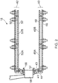
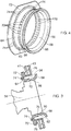
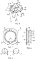
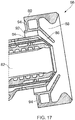
- Each seal 58 is additionally cooled by supplying coolant, air, through the second coolant apertures 74 in the radially extending flange 72 of the seal 58 and this supplies coolant into the annular space 78 between the seal 58 and the locating ring 76.
- the supply of coolant into the annular space 78 provides additional cooling of the upstream, cold, surface of the third, downstream, portion 68 of the seal 58 and prevents or restricts the flow of hot combustion gases into the annular space 78 and hence reduces the temperature of the third, downstream, portion 68 of the seal 58 and reduces melting and oxidation of the third, downstream, portion 68 of the seal 58.
- the coolant, air, supplied by the second coolant apertures 74 purges the annular space 78 of hot combustion gases.
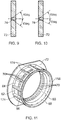
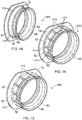
- FIGS 11 and 12 show the seal 158 according to the invention in more detail.
- Each seal 158 is similar to that shown in figures 3 to 10 and like parts are denoted by like numerals but does not have second coolant apertures in the radially extending flange 72.
- Each seal 158 has a plurality of thermal conductors 174 extending axially from the radially extending flange 72 to the third, downstream, portion 68 of the seal 158.
- Each seal 158 has a plurality of circumferentially spaced thermal conductors 174 extending axially from the radially extending flange 72 to the third, downstream, portion 68 of the seal 158.
- the seals 158 may be manufactured for example by casting and then drilling, e.g. ECM, EDM or laser drilling, the coolant apertures 70 and 74.
- the seals 158 may be manufactured by casting using cores to define the coolant apertures 70 and 74 and then removing, e.g. dissolving, the cores.
- the seals 158 may be manufactured by additive layer manufacturing, e.g. powder bed laser deposition.
- the total flow through the second coolant apertures 74 is required to be optimised to ensure the coolant, air, is sufficient to purge the annular space 78 of hot combustion gas and prevent hot combustion gas ingress throughout the flight cycle whilst minimising the interaction with the fuel and air mixture injected by the fuel injector 56.
- the axes of the second cooling apertures and/or the axes of the first cooling apertures direction may be orientated to establish a swirling flow of coolant within the annular space between the seal and the locating ring to enhance convective cooling of the seal whilst minimising the interaction of coolant flow with the swirling fuel and air mixture from the fuel injector.
Landscapes
- Engineering & Computer Science (AREA)
- Chemical & Material Sciences (AREA)
- Combustion & Propulsion (AREA)
- Mechanical Engineering (AREA)
- General Engineering & Computer Science (AREA)
- Fuel-Injection Apparatus (AREA)
- Turbine Rotor Nozzle Sealing (AREA)
Claims (19)
- Brennkammer (15), umfassend eine stromaufwärtige Endwand (44), mindestens eine ringförmige Wand (40, 42), mindestens einen Kraftstoffinjektor (56) und mindestens eine Dichtung (58, 158, 258);
wobei die mindestens eine ringförmige Wand (40, 42) an der stromaufwärtigen Endwand (44) befestigt ist;
wobei die stromaufwärtige Endwand (44) mindestens eine Öffnung (54) aufweist,
wobei jeder Kraftstoffinjektor (56) in einer entsprechenden der Öffnungen (54) in der stromaufwärtigen Endwand (44) angeordnet ist;
wobei jede Dichtung (58, 158, 258) in einer entsprechenden der Öffnungen (54) in der stromaufwärtigen Endwand (44) und um den entsprechenden der Kraftstoffinjektoren (56) angeordnet ist, wobei jede Dichtung (58, 158, 258) eine Innenfläche (60), die dem entsprechenden der Kraftstoffinjektoren (56) zugewandt ist, und einer Außenfläche (62), die dem entsprechenden der Kraftstoffinjektoren (56) abgewandt ist, aufweist, wobei jede Dichtung (58, 158, 258) an dem entsprechenden der Kraftstoffinjektoren (56) anliegt, wobei das stromabwärtige Ende (68) jeder Dichtung (58, 158, 258) in stromabwärtiger Richtung an Durchmesser zunimmt, wobei das stromaufwärtige Ende (64) jeder Dichtung (58, 158, 258) einen sich radial erstreckenden Flansch (72) aufweist, wobei das stromabwärtige Ende (68) jeder Dichtung (58, 158, 258) axial stromabwärts der stromaufwärtigen Endwand (44) positioniert ist, wobei jede Dichtung (58, 158, 258) in der entsprechenden der Öffnungen (54) in der stromaufwärtigen Endwand (44) so angeordnet ist, dass ein ringförmiger Raum (78) zwischen der Außenfläche (62) der Dichtung (58, 158, 258) und der stromaufwärtigen Endwand (44) gebildet wird, dadurch gekennzeichnet, dass jede Dichtung (158, 258) mehrere Wärmeleiter (174) aufweist, die sich axial vom sich radial erstreckenden Flansch (72) zum stromabwärtigen Ende (68) der Dichtung (158, 258) erstrecken. - Brennkammer nach Anspruch 1, wobei jede Dichtung (58, 258) mindestens eine Reihe von in Umfangsrichtung beabstandeten zweiten Kühlmittelöffnungen (74) aufweist, die sich axial durch den sich radial erstreckenden Flansch (72) erstrecken.
- Brennkammer nach Anspruch 2, wobei jede Dichtung (58, 258) mehrere Reihen von in Umfangsrichtung beabstandeten zweiten Kühlmittelöffnungen (74) aufweist, die sich axial durch den sich radial erstreckenden Flansch (72) erstrecken.
- Brennkammer nach Anspruch 2 oder Anspruch 3, wobei der Durchmesser der zweiten Kühlmittelöffnungen (74) kleiner oder gleich 3 mm und größer oder gleich 0,4 mm ist.
- Brennkammer nach Anspruch 2, Anspruch 3 oder Anspruch 4, wobei die Achsen der zweiten Kühlmittelöffnungen (74) radial nach innen abgewinkelt sind oder radial nach außen abgewinkelt sind.
- Brennkammer nach Anspruch 5, wobei die zweiten Kühlmittelöffnungen (74) in einem Winkel von weniger als oder gleich 60° radial nach innen abgewinkelt sind oder die zweiten Kühlmittelöffnungen (74) in einem Winkel von weniger als oder gleich 60° radial nach außen abgewinkelt sind.
- Brennkammer nach Anspruch 2, Anspruch 3 oder Anspruch 4, wobei sich die zweiten Kühlmittelöffnungen (74) rein senkrecht durch den sich radial erstreckenden Flansch (72) erstrecken.
- Brennkammer nach einem der Ansprüche 2 bis 7, wobei die Achsen der zweiten Kühlmittelöffnungen (74) in Umfangsrichtung abgewinkelt sind.
- Brennkammer nach Anspruch 8, wobei der Kraftstoffinjektor konfiguriert ist, um ein wirbelndes Kraftstoff- und Luftgemisch zu erzeugen, wobei die zweiten Kühlmittelöffnungen (74) in Umfangsrichtung in Richtung des wirbelnden Kraftstoff- und Luftgemisches vom Kraftstoffinjektor (56) abgewinkelt sind, wobei die zweiten Kühlmittelöffnungen (74) in Umfangsrichtung in einem Winkel von weniger als oder gleich 60° abgewinkelt sind.
- Brennkammer nach Anspruch 8, wobei der Kraftstoffinjektor konfiguriert ist, um ein wirbelndes Kraftstoff- und Luftgemisch zu erzeugen, wobei die zweiten Kühlmittelöffnungen (74) in Umfangsrichtung in der entgegengesetzten Richtung des wirbelnden Kraftstoff- und Luftgemisches vom Kraftstoffinjektor (56) abgewinkelt sind, wobei die zweiten Kühlmittelöffnungen (74) in Umfangsrichtung in einem Winkel von weniger als oder gleich 10° abgewinkelt sind.
- Brennkammer nach einem der Ansprüche 2 bis 10, wobei die zweiten Kühlmittelöffnungen (74) in dem sich radial erstreckenden Flansch (72) in einem Radius kleiner oder gleich dem Radius der Außenfläche der Dichtung + (0,6 x (Radius der Öffnung in der stromaufwärtigen Endwand - Radius der Außenfläche der Dichtung)) und in einem Radius größer oder gleich dem Radius der Außenfläche der Dichtung + (0,3 x (Radius der Öffnung in der stromaufwärtigen Endwand - Radius der Außenfläche der Dichtung)) angeordnet sind.
- Brennkammer nach einem der Ansprüche 1 bis 11, wobei jede Dichtung (158, 258) mehrere in Umfangsrichtung beabstandete Wärmeleiter (174) aufweist, die sich axial vom sich radial erstreckenden Flansch (72) zum stromabwärtigen Ende (68) der Dichtung (158, 258) erstrecken.
- Brennkammer nach einem der Ansprüche 1 bis 12, wobei sich jeder Wärmeleiter (174) von der Außenfläche (62) der Dichtung (158, 258) radial nach außen erstreckt.
- Brennkammer nach einem der Ansprüche 1 bis 13, wobei sich jeder Wärmeleiter (174) von der Außenfläche (62) der Dichtung (158, 258) über den gesamten axialen Abstand zwischen dem sich radial erstreckenden Flansch (72) und dem stromabwärtigen Ende (68) der Dichtung (158, 258) radial nach außen erstreckt.
- Brennkammer nach einem der Ansprüche 1 bis 14, wobei die Wärmeleiter (174) hohl sind.
- Brennkammer nach einem der Ansprüche 1 bis 15, wobei jeder Wärmeleiter (174) eine radial äußere Oberfläche (176), die von der Außenfläche (62) der Dichtung (158, 258) entfernt ist, und Seitenflächen (178), die sich radial von der radial äußeren Oberfläche (176) zur Außenfläche (62) der Dichtung (158, 258) erstrecken, aufweist, wobei die Oberfläche der radial äußeren Oberfläche (176) des Wärmeleiters (174) geteilt durch das Doppelte der Oberfläche die Seitenflächen (176) des Wärmeleiters (174) kleiner als 1 ist.
- Brennkammer nach einem der Ansprüche 2 bis 16, wobei zwischen 1 und 10 zweite Kühlmittelöffnungen (74) vorhanden sind, die sich axial durch den sich radial erstreckenden Flansch (72) erstrecken, die zwischen jedem Paar von in Umfangsrichtung beabstandeten Wärmeleitern (174) positioniert sind.
- Brennkammer nach einem der Ansprüche 1 bis 17, wobei zwischen 1 und 10 erste Kühlmittelöffnungen (70) vorhanden sind, die sich durch die Dichtung (258) von der Innenfläche (60) zur Außenfläche (62) erstrecken, die zwischen jedem Paar von in Umfangsrichtung beabstandeten Wärmeleitern (174) positioniert sind.
- Brennkammer nach Anspruch 18, wobei jede erste Kühlmittelöffnung (70) einen Einlass in der Innenfläche (60) und einen Auslass in der Außenfläche (62) der Dichtung (58, 158, 258) aufweist, wobei die ersten Kühlmittelöffnungen (70) stromaufwärts des stromabwärtigen Endes (68) der Dichtung (58, 158, 258) angeordnet sind, wobei sich die ersten Kühlmittelöffnungen (70) mit axialen und radialen Komponenten dadurch erstrecken, wobei der Auslass jeder ersten Kühlmittelöffnung (70) axial in stromabwärtiger Richtung von ihrem Einlass beabstandet sein, wobei der Auslass jeder ersten Kühlmittelöffnung (70) radial von ihrem Einlass beabstandet ist.
Applications Claiming Priority (1)
| Application Number | Priority Date | Filing Date | Title |
|---|---|---|---|
| GR20160100637 | 2016-12-20 |
Publications (2)
| Publication Number | Publication Date |
|---|---|
| EP3339739A1 EP3339739A1 (de) | 2018-06-27 |
| EP3339739B1 true EP3339739B1 (de) | 2021-06-30 |
Family
ID=58462618
Family Applications (1)
| Application Number | Title | Priority Date | Filing Date |
|---|---|---|---|
| EP17203265.8A Active EP3339739B1 (de) | 2016-12-20 | 2017-11-23 | Brennkammer und brennkammerkraftstoffinjektordichtung |
Country Status (3)
| Country | Link |
|---|---|
| US (1) | US10704517B2 (de) |
| EP (1) | EP3339739B1 (de) |
| GB (1) | GB201701380D0 (de) |
Families Citing this family (4)
| Publication number | Priority date | Publication date | Assignee | Title |
|---|---|---|---|---|
| US10330204B2 (en) * | 2017-11-10 | 2019-06-25 | Rolls-Royce Deutschland Ltd & Co Kg | Burner seal of a gas turbine and method for manufacturing the same |
| DE102018125698A1 (de) | 2018-10-17 | 2020-04-23 | Man Energy Solutions Se | Gasturbinenbrennkammer |
| EP4108898B1 (de) * | 2020-02-20 | 2025-01-08 | Kawasaki Jukogyo Kabushiki Kaisha | Flanschkühlstruktur für ein gasturbinentriebwerk |
| CN117329361B (zh) * | 2023-12-01 | 2024-01-30 | 中国空气动力研究与发展中心超高速空气动力研究所 | 风洞用高温高压部段密封结构及其安装方法和试验方法 |
Family Cites Families (40)
| Publication number | Priority date | Publication date | Assignee | Title |
|---|---|---|---|---|
| DE1301644B (de) * | 1965-11-23 | 1969-08-21 | Daimler Benz Ag | Einrichtung zur Belueftung von Einspritzduesen fuer Gasturbinen-triebwerke, insbesondere Flugtriebwerke |
| US4365470A (en) | 1980-04-02 | 1982-12-28 | United Technologies Corporation | Fuel nozzle guide and seal for a gas turbine engine |
| US4322945A (en) | 1980-04-02 | 1982-04-06 | United Technologies Corporation | Fuel nozzle guide heat shield for a gas turbine engine |
| US4870818A (en) * | 1986-04-18 | 1989-10-03 | United Technologies Corporation | Fuel nozzle guide structure and retainer for a gas turbine engine |
| US4686823A (en) * | 1986-04-28 | 1987-08-18 | United Technologies Corporation | Sliding joint for an annular combustor |
| US4914918A (en) * | 1988-09-26 | 1990-04-10 | United Technologies Corporation | Combustor segmented deflector |
| US4934145A (en) * | 1988-10-12 | 1990-06-19 | United Technologies Corporation | Combustor bulkhead heat shield assembly |
| GB9018013D0 (en) * | 1990-08-16 | 1990-10-03 | Rolls Royce Plc | Gas turbine engine combustor |
| US5419115A (en) * | 1994-04-29 | 1995-05-30 | United Technologies Corporation | Bulkhead and fuel nozzle guide assembly for an annular combustion chamber |
| DE4427222A1 (de) * | 1994-08-01 | 1996-02-08 | Bmw Rolls Royce Gmbh | Hitzeschild für eine Gasturbinen-Brennkammer |
| DE19508111A1 (de) | 1995-03-08 | 1996-09-12 | Bmw Rolls Royce Gmbh | Hitzeschild-Anordnung für eine Gasturbinen-Brennkammer |
| US6032457A (en) | 1996-06-27 | 2000-03-07 | United Technologies Corporation | Fuel nozzle guide |
| GB9623195D0 (en) | 1996-11-07 | 1997-01-08 | Rolls Royce Plc | Gas turbine engine combustor |
| US5974805A (en) * | 1997-10-28 | 1999-11-02 | Rolls-Royce Plc | Heat shielding for a turbine combustor |
| DE10048864A1 (de) | 2000-10-02 | 2002-04-11 | Rolls Royce Deutschland | Brennkammerkopf für eine Gasturbine |
| FR2829228B1 (fr) | 2001-08-28 | 2005-07-15 | Snecma Moteurs | Chambre de combustion annulaire a double tete etagee |
| US7506512B2 (en) | 2005-06-07 | 2009-03-24 | Honeywell International Inc. | Advanced effusion cooling schemes for combustor domes |
| FR2891350A1 (fr) * | 2005-09-29 | 2007-03-30 | Snecma Sa | Dispositif de guidage d'un element dans un orifice d'une paroi de chambre de combustion de turbomachine |
| FR2899314B1 (fr) | 2006-03-30 | 2008-05-09 | Snecma Sa | Dispositif d'injection d'un melange d'air et de carburant, chambre de combustion et turbomachine munies d'un tel dispositif |
| US7861530B2 (en) * | 2007-03-30 | 2011-01-04 | Pratt & Whitney Canada Corp. | Combustor floating collar with louver |
| DE102009032277A1 (de) * | 2009-07-08 | 2011-01-20 | Rolls-Royce Deutschland Ltd & Co Kg | Brennkammerkopf einer Gasturbine |
| US8726631B2 (en) * | 2009-11-23 | 2014-05-20 | Honeywell International Inc. | Dual walled combustors with impingement cooled igniters |
| DE102011014670A1 (de) | 2011-03-22 | 2012-09-27 | Rolls-Royce Deutschland Ltd & Co Kg | Segmentierter Brennkammerkopf |
| GB201107095D0 (en) * | 2011-04-28 | 2011-06-08 | Rolls Royce Plc | A head part of an annular combustion chamber |
| GB201107090D0 (en) * | 2011-04-28 | 2011-06-08 | Rolls Royce Plc | A head part of an annular combustion chamber |
| US8745988B2 (en) | 2011-09-06 | 2014-06-10 | Pratt & Whitney Canada Corp. | Pin fin arrangement for heat shield of gas turbine engine |
| GB2499196B (en) | 2012-02-07 | 2017-08-02 | Rolls Royce Plc | Combustor head arrangement |
| US9097130B2 (en) * | 2012-09-13 | 2015-08-04 | General Electric Company | Seal for use between injector and combustion chamber in gas turbine |
| WO2014081334A1 (en) * | 2012-11-21 | 2014-05-30 | General Electric Company | Anti-coking liquid fuel cartridge |
| US9587831B2 (en) * | 2012-11-27 | 2017-03-07 | United Technologies Corporation | Cooled combustor seal |
| GB2511563B (en) * | 2013-03-08 | 2015-06-24 | Rolls Royce Plc | A combustion chamber heat shield and seal assembly and a method of manufacturing a combustion chamber heat shield and seal assembly |
| DE102013007443A1 (de) | 2013-04-30 | 2014-10-30 | Rolls-Royce Deutschland Ltd & Co Kg | Brennerdichtung für Gasturbinen-Brennkammerkopf und Hitzeschild |
| US9803554B2 (en) | 2013-08-12 | 2017-10-31 | Unison Industries, Llc | Fuel igniter assembly having heat-dissipating element and methods of using same |
| US9625156B2 (en) * | 2013-10-30 | 2017-04-18 | Honeywell International Inc. | Gas turbine engines having fuel injector shrouds with interior ribs |
| US9982890B2 (en) * | 2013-11-20 | 2018-05-29 | Pratt & Whitney Canada Corp. | Combustor dome heat shield |
| GB201321193D0 (en) * | 2013-12-02 | 2014-01-15 | Rolls Royce Plc | A combustion chamber assembly |
| US20160348911A1 (en) | 2013-12-12 | 2016-12-01 | Siemens Energy, Inc. | W501 d5/d5a df42 combustion system |
| GB201413193D0 (en) | 2014-07-25 | 2014-09-10 | Rolls Royce Plc | A method and an apparatus for producing cooling apertures in a combustion chamber head |
| FR3026827B1 (fr) | 2014-10-01 | 2019-06-07 | Safran Aircraft Engines | Chambre de combustion de turbomachine |
| US10670272B2 (en) * | 2014-12-11 | 2020-06-02 | Raytheon Technologies Corporation | Fuel injector guide(s) for a turbine engine combustor |
-
2017
- 2017-01-27 GB GBGB1701380.6A patent/GB201701380D0/en not_active Ceased
- 2017-11-23 EP EP17203265.8A patent/EP3339739B1/de active Active
- 2017-12-11 US US15/837,446 patent/US10704517B2/en active Active
Also Published As
| Publication number | Publication date |
|---|---|
| US20180171953A1 (en) | 2018-06-21 |
| GB201701380D0 (en) | 2017-03-15 |
| EP3339739A1 (de) | 2018-06-27 |
| US10704517B2 (en) | 2020-07-07 |
Similar Documents
| Publication | Publication Date | Title |
|---|---|---|
| EP3460332B1 (de) | Brennkammer | |
| US10712003B2 (en) | Combustion chamber assembly | |
| US10907830B2 (en) | Combustor chamber arrangement with sealing ring | |
| US9297533B2 (en) | Combustor and a method for cooling the combustor | |
| US9810148B2 (en) | Self-cooled orifice structure | |
| EP3220047B1 (de) | Gasturbinenstromhülsenhalterung | |
| US9851105B2 (en) | Self-cooled orifice structure | |
| US10655855B2 (en) | Gas turbine engine wall assembly with support shell contour regions | |
| US11112117B2 (en) | Fuel nozzle cooling structure | |
| US20190024895A1 (en) | Combustor dilution structure for gas turbine engine | |
| US10816212B2 (en) | Combustion chamber having a hook and groove connection | |
| US10704517B2 (en) | Combustion chamber and a combustion chamber fuel injector seal | |
| EP2971973B1 (de) | Brennkammerplatte und brennkammer mit hitzeschild mit erhöhter beständigkeit | |
| US10408456B2 (en) | Combustion chamber assembly | |
| US11313560B2 (en) | Combustor assembly for a heat engine | |
| US20220325891A1 (en) | Dilution horn pair for a gas turbine engine combustor | |
| EP3309458B1 (de) | Brennkammer und brennkammerkraftstoffinjektordichtung | |
| US9995219B2 (en) | Turbine engine wall having at least some cooling orifices that are plugged | |
| US10655856B2 (en) | Dilution passage arrangement for gas turbine engine combustor | |
| US11846419B2 (en) | Dome-deflector joint cooling arrangement | |
| EP3434978A1 (de) | Brennkammer und brennkammerkraftstoffinjektordichtung | |
| US20090293490A1 (en) | Combustor wall with improved cooling | |
| EP3315864B1 (de) | Gegossene brennkammerauskleidungsplatte mit abgerundeter verdünnungsdurchgangshülse für eine gasturbinenmotorbrennkammer |
Legal Events
| Date | Code | Title | Description |
|---|---|---|---|
| PUAI | Public reference made under article 153(3) epc to a published international application that has entered the european phase |
Free format text: ORIGINAL CODE: 0009012 |
|
| STAA | Information on the status of an ep patent application or granted ep patent |
Free format text: STATUS: THE APPLICATION HAS BEEN PUBLISHED |
|
| AK | Designated contracting states |
Kind code of ref document: A1 Designated state(s): AL AT BE BG CH CY CZ DE DK EE ES FI FR GB GR HR HU IE IS IT LI LT LU LV MC MK MT NL NO PL PT RO RS SE SI SK SM TR |
|
| AX | Request for extension of the european patent |
Extension state: BA ME |
|
| STAA | Information on the status of an ep patent application or granted ep patent |
Free format text: STATUS: REQUEST FOR EXAMINATION WAS MADE |
|
| 17P | Request for examination filed |
Effective date: 20181211 |
|
| RBV | Designated contracting states (corrected) |
Designated state(s): AL AT BE BG CH CY CZ DE DK EE ES FI FR GB GR HR HU IE IS IT LI LT LU LV MC MK MT NL NO PL PT RO RS SE SI SK SM TR |
|
| RAP1 | Party data changed (applicant data changed or rights of an application transferred) |
Owner name: ROLLS-ROYCE PLC |
|
| GRAP | Despatch of communication of intention to grant a patent |
Free format text: ORIGINAL CODE: EPIDOSNIGR1 |
|
| STAA | Information on the status of an ep patent application or granted ep patent |
Free format text: STATUS: GRANT OF PATENT IS INTENDED |
|
| GRAS | Grant fee paid |
Free format text: ORIGINAL CODE: EPIDOSNIGR3 |
|
| INTG | Intention to grant announced |
Effective date: 20210429 |
|
| GRAA | (expected) grant |
Free format text: ORIGINAL CODE: 0009210 |
|
| STAA | Information on the status of an ep patent application or granted ep patent |
Free format text: STATUS: THE PATENT HAS BEEN GRANTED |
|
| AK | Designated contracting states |
Kind code of ref document: B1 Designated state(s): AL AT BE BG CH CY CZ DE DK EE ES FI FR GB GR HR HU IE IS IT LI LT LU LV MC MK MT NL NO PL PT RO RS SE SI SK SM TR |
|
| REG | Reference to a national code |
Ref country code: CH Ref legal event code: EP |
|
| REG | Reference to a national code |
Ref country code: AT Ref legal event code: REF Ref document number: 1406673 Country of ref document: AT Kind code of ref document: T Effective date: 20210715 |
|
| REG | Reference to a national code |
Ref country code: DE Ref legal event code: R096 Ref document number: 602017041146 Country of ref document: DE |
|
| REG | Reference to a national code |
Ref country code: IE Ref legal event code: FG4D |
|
| REG | Reference to a national code |
Ref country code: LT Ref legal event code: MG9D |
|
| PG25 | Lapsed in a contracting state [announced via postgrant information from national office to epo] |
Ref country code: FI Free format text: LAPSE BECAUSE OF FAILURE TO SUBMIT A TRANSLATION OF THE DESCRIPTION OR TO PAY THE FEE WITHIN THE PRESCRIBED TIME-LIMIT Effective date: 20210630 Ref country code: BG Free format text: LAPSE BECAUSE OF FAILURE TO SUBMIT A TRANSLATION OF THE DESCRIPTION OR TO PAY THE FEE WITHIN THE PRESCRIBED TIME-LIMIT Effective date: 20210930 Ref country code: HR Free format text: LAPSE BECAUSE OF FAILURE TO SUBMIT A TRANSLATION OF THE DESCRIPTION OR TO PAY THE FEE WITHIN THE PRESCRIBED TIME-LIMIT Effective date: 20210630 |
|
| REG | Reference to a national code |
Ref country code: NL Ref legal event code: MP Effective date: 20210630 |
|
| REG | Reference to a national code |
Ref country code: AT Ref legal event code: MK05 Ref document number: 1406673 Country of ref document: AT Kind code of ref document: T Effective date: 20210630 |
|
| PG25 | Lapsed in a contracting state [announced via postgrant information from national office to epo] |
Ref country code: GR Free format text: LAPSE BECAUSE OF FAILURE TO SUBMIT A TRANSLATION OF THE DESCRIPTION OR TO PAY THE FEE WITHIN THE PRESCRIBED TIME-LIMIT Effective date: 20211001 Ref country code: LV Free format text: LAPSE BECAUSE OF FAILURE TO SUBMIT A TRANSLATION OF THE DESCRIPTION OR TO PAY THE FEE WITHIN THE PRESCRIBED TIME-LIMIT Effective date: 20210630 Ref country code: NO Free format text: LAPSE BECAUSE OF FAILURE TO SUBMIT A TRANSLATION OF THE DESCRIPTION OR TO PAY THE FEE WITHIN THE PRESCRIBED TIME-LIMIT Effective date: 20210930 Ref country code: RS Free format text: LAPSE BECAUSE OF FAILURE TO SUBMIT A TRANSLATION OF THE DESCRIPTION OR TO PAY THE FEE WITHIN THE PRESCRIBED TIME-LIMIT Effective date: 20210630 Ref country code: SE Free format text: LAPSE BECAUSE OF FAILURE TO SUBMIT A TRANSLATION OF THE DESCRIPTION OR TO PAY THE FEE WITHIN THE PRESCRIBED TIME-LIMIT Effective date: 20210630 |
|
| PG25 | Lapsed in a contracting state [announced via postgrant information from national office to epo] |
Ref country code: CZ Free format text: LAPSE BECAUSE OF FAILURE TO SUBMIT A TRANSLATION OF THE DESCRIPTION OR TO PAY THE FEE WITHIN THE PRESCRIBED TIME-LIMIT Effective date: 20210630 Ref country code: EE Free format text: LAPSE BECAUSE OF FAILURE TO SUBMIT A TRANSLATION OF THE DESCRIPTION OR TO PAY THE FEE WITHIN THE PRESCRIBED TIME-LIMIT Effective date: 20210630 Ref country code: AT Free format text: LAPSE BECAUSE OF FAILURE TO SUBMIT A TRANSLATION OF THE DESCRIPTION OR TO PAY THE FEE WITHIN THE PRESCRIBED TIME-LIMIT Effective date: 20210630 Ref country code: PT Free format text: LAPSE BECAUSE OF FAILURE TO SUBMIT A TRANSLATION OF THE DESCRIPTION OR TO PAY THE FEE WITHIN THE PRESCRIBED TIME-LIMIT Effective date: 20211102 Ref country code: RO Free format text: LAPSE BECAUSE OF FAILURE TO SUBMIT A TRANSLATION OF THE DESCRIPTION OR TO PAY THE FEE WITHIN THE PRESCRIBED TIME-LIMIT Effective date: 20210630 Ref country code: NL Free format text: LAPSE BECAUSE OF FAILURE TO SUBMIT A TRANSLATION OF THE DESCRIPTION OR TO PAY THE FEE WITHIN THE PRESCRIBED TIME-LIMIT Effective date: 20210630 Ref country code: ES Free format text: LAPSE BECAUSE OF FAILURE TO SUBMIT A TRANSLATION OF THE DESCRIPTION OR TO PAY THE FEE WITHIN THE PRESCRIBED TIME-LIMIT Effective date: 20210630 Ref country code: SK Free format text: LAPSE BECAUSE OF FAILURE TO SUBMIT A TRANSLATION OF THE DESCRIPTION OR TO PAY THE FEE WITHIN THE PRESCRIBED TIME-LIMIT Effective date: 20210630 Ref country code: SM Free format text: LAPSE BECAUSE OF FAILURE TO SUBMIT A TRANSLATION OF THE DESCRIPTION OR TO PAY THE FEE WITHIN THE PRESCRIBED TIME-LIMIT Effective date: 20210630 |
|
| PG25 | Lapsed in a contracting state [announced via postgrant information from national office to epo] |
Ref country code: PL Free format text: LAPSE BECAUSE OF FAILURE TO SUBMIT A TRANSLATION OF THE DESCRIPTION OR TO PAY THE FEE WITHIN THE PRESCRIBED TIME-LIMIT Effective date: 20210630 |
|
| REG | Reference to a national code |
Ref country code: DE Ref legal event code: R097 Ref document number: 602017041146 Country of ref document: DE |
|
| PG25 | Lapsed in a contracting state [announced via postgrant information from national office to epo] |
Ref country code: DK Free format text: LAPSE BECAUSE OF FAILURE TO SUBMIT A TRANSLATION OF THE DESCRIPTION OR TO PAY THE FEE WITHIN THE PRESCRIBED TIME-LIMIT Effective date: 20210630 |
|
| PLBE | No opposition filed within time limit |
Free format text: ORIGINAL CODE: 0009261 |
|
| STAA | Information on the status of an ep patent application or granted ep patent |
Free format text: STATUS: NO OPPOSITION FILED WITHIN TIME LIMIT |
|
| PG25 | Lapsed in a contracting state [announced via postgrant information from national office to epo] |
Ref country code: AL Free format text: LAPSE BECAUSE OF FAILURE TO SUBMIT A TRANSLATION OF THE DESCRIPTION OR TO PAY THE FEE WITHIN THE PRESCRIBED TIME-LIMIT Effective date: 20210630 |
|
| 26N | No opposition filed |
Effective date: 20220331 |
|
| PG25 | Lapsed in a contracting state [announced via postgrant information from national office to epo] |
Ref country code: MC Free format text: LAPSE BECAUSE OF FAILURE TO SUBMIT A TRANSLATION OF THE DESCRIPTION OR TO PAY THE FEE WITHIN THE PRESCRIBED TIME-LIMIT Effective date: 20210630 |
|
| REG | Reference to a national code |
Ref country code: CH Ref legal event code: PL |
|
| PG25 | Lapsed in a contracting state [announced via postgrant information from national office to epo] |
Ref country code: LU Free format text: LAPSE BECAUSE OF NON-PAYMENT OF DUE FEES Effective date: 20211123 Ref country code: IT Free format text: LAPSE BECAUSE OF FAILURE TO SUBMIT A TRANSLATION OF THE DESCRIPTION OR TO PAY THE FEE WITHIN THE PRESCRIBED TIME-LIMIT Effective date: 20210630 Ref country code: BE Free format text: LAPSE BECAUSE OF NON-PAYMENT OF DUE FEES Effective date: 20211130 |
|
| REG | Reference to a national code |
Ref country code: BE Ref legal event code: MM Effective date: 20211130 |
|
| PG25 | Lapsed in a contracting state [announced via postgrant information from national office to epo] |
Ref country code: IE Free format text: LAPSE BECAUSE OF NON-PAYMENT OF DUE FEES Effective date: 20211123 |
|
| PG25 | Lapsed in a contracting state [announced via postgrant information from national office to epo] |
Ref country code: LT Free format text: LAPSE BECAUSE OF FAILURE TO SUBMIT A TRANSLATION OF THE DESCRIPTION OR TO PAY THE FEE WITHIN THE PRESCRIBED TIME-LIMIT Effective date: 20210630 |
|
| PG25 | Lapsed in a contracting state [announced via postgrant information from national office to epo] |
Ref country code: HU Free format text: LAPSE BECAUSE OF FAILURE TO SUBMIT A TRANSLATION OF THE DESCRIPTION OR TO PAY THE FEE WITHIN THE PRESCRIBED TIME-LIMIT; INVALID AB INITIO Effective date: 20171123 |
|
| PG25 | Lapsed in a contracting state [announced via postgrant information from national office to epo] |
Ref country code: CY Free format text: LAPSE BECAUSE OF FAILURE TO SUBMIT A TRANSLATION OF THE DESCRIPTION OR TO PAY THE FEE WITHIN THE PRESCRIBED TIME-LIMIT Effective date: 20210630 |
|
| P01 | Opt-out of the competence of the unified patent court (upc) registered |
Effective date: 20230528 |
|
| PG25 | Lapsed in a contracting state [announced via postgrant information from national office to epo] |
Ref country code: LI Free format text: LAPSE BECAUSE OF NON-PAYMENT OF DUE FEES Effective date: 20220630 Ref country code: CH Free format text: LAPSE BECAUSE OF NON-PAYMENT OF DUE FEES Effective date: 20220630 |
|
| PG25 | Lapsed in a contracting state [announced via postgrant information from national office to epo] |
Ref country code: MK Free format text: LAPSE BECAUSE OF FAILURE TO SUBMIT A TRANSLATION OF THE DESCRIPTION OR TO PAY THE FEE WITHIN THE PRESCRIBED TIME-LIMIT Effective date: 20210630 |
|
| PG25 | Lapsed in a contracting state [announced via postgrant information from national office to epo] |
Ref country code: TR Free format text: LAPSE BECAUSE OF FAILURE TO SUBMIT A TRANSLATION OF THE DESCRIPTION OR TO PAY THE FEE WITHIN THE PRESCRIBED TIME-LIMIT Effective date: 20210630 |
|
| PG25 | Lapsed in a contracting state [announced via postgrant information from national office to epo] |
Ref country code: MT Free format text: LAPSE BECAUSE OF FAILURE TO SUBMIT A TRANSLATION OF THE DESCRIPTION OR TO PAY THE FEE WITHIN THE PRESCRIBED TIME-LIMIT Effective date: 20210630 |
|
| PGFP | Annual fee paid to national office [announced via postgrant information from national office to epo] |
Ref country code: DE Payment date: 20251126 Year of fee payment: 9 |
|
| PGFP | Annual fee paid to national office [announced via postgrant information from national office to epo] |
Ref country code: GB Payment date: 20251125 Year of fee payment: 9 |
|
| PGFP | Annual fee paid to national office [announced via postgrant information from national office to epo] |
Ref country code: FR Payment date: 20251124 Year of fee payment: 9 |