EP3339737B1 - Wärmeisolierende kachel für eine brennkammer einer gasturbine - Google Patents
Wärmeisolierende kachel für eine brennkammer einer gasturbine Download PDFInfo
- Publication number
- EP3339737B1 EP3339737B1 EP17209153.0A EP17209153A EP3339737B1 EP 3339737 B1 EP3339737 B1 EP 3339737B1 EP 17209153 A EP17209153 A EP 17209153A EP 3339737 B1 EP3339737 B1 EP 3339737B1
- Authority
- EP
- European Patent Office
- Prior art keywords
- thermoinsulating
- tile
- marker substance
- face
- combustion chamber
- Prior art date
- Legal status (The legal status is an assumption and is not a legal conclusion. Google has not performed a legal analysis and makes no representation as to the accuracy of the status listed.)
- Active
Links
Images


Classifications
-
- F—MECHANICAL ENGINEERING; LIGHTING; HEATING; WEAPONS; BLASTING
- F23—COMBUSTION APPARATUS; COMBUSTION PROCESSES
- F23M—CASINGS, LININGS, WALLS OR DOORS SPECIALLY ADAPTED FOR COMBUSTION CHAMBERS, e.g. FIREBRIDGES; DEVICES FOR DEFLECTING AIR, FLAMES OR COMBUSTION PRODUCTS IN COMBUSTION CHAMBERS; SAFETY ARRANGEMENTS SPECIALLY ADAPTED FOR COMBUSTION APPARATUS; DETAILS OF COMBUSTION CHAMBERS, NOT OTHERWISE PROVIDED FOR
- F23M5/00—Casings; Linings; Walls
- F23M5/02—Casings; Linings; Walls characterised by the shape of the bricks or blocks used
-
- F—MECHANICAL ENGINEERING; LIGHTING; HEATING; WEAPONS; BLASTING
- F23—COMBUSTION APPARATUS; COMBUSTION PROCESSES
- F23R—GENERATING COMBUSTION PRODUCTS OF HIGH PRESSURE OR HIGH VELOCITY, e.g. GAS-TURBINE COMBUSTION CHAMBERS
- F23R3/00—Continuous combustion chambers using liquid or gaseous fuel
-
- F—MECHANICAL ENGINEERING; LIGHTING; HEATING; WEAPONS; BLASTING
- F23—COMBUSTION APPARATUS; COMBUSTION PROCESSES
- F23R—GENERATING COMBUSTION PRODUCTS OF HIGH PRESSURE OR HIGH VELOCITY, e.g. GAS-TURBINE COMBUSTION CHAMBERS
- F23R3/00—Continuous combustion chambers using liquid or gaseous fuel
- F23R3/002—Wall structures
-
- F—MECHANICAL ENGINEERING; LIGHTING; HEATING; WEAPONS; BLASTING
- F23—COMBUSTION APPARATUS; COMBUSTION PROCESSES
- F23R—GENERATING COMBUSTION PRODUCTS OF HIGH PRESSURE OR HIGH VELOCITY, e.g. GAS-TURBINE COMBUSTION CHAMBERS
- F23R3/00—Continuous combustion chambers using liquid or gaseous fuel
- F23R3/007—Continuous combustion chambers using liquid or gaseous fuel constructed mainly of ceramic components
-
- F—MECHANICAL ENGINEERING; LIGHTING; HEATING; WEAPONS; BLASTING
- F23—COMBUSTION APPARATUS; COMBUSTION PROCESSES
- F23R—GENERATING COMBUSTION PRODUCTS OF HIGH PRESSURE OR HIGH VELOCITY, e.g. GAS-TURBINE COMBUSTION CHAMBERS
- F23R3/00—Continuous combustion chambers using liquid or gaseous fuel
- F23R3/02—Continuous combustion chambers using liquid or gaseous fuel characterised by the air-flow or gas-flow configuration
-
- B—PERFORMING OPERATIONS; TRANSPORTING
- B23—MACHINE TOOLS; METAL-WORKING NOT OTHERWISE PROVIDED FOR
- B23P—METAL-WORKING NOT OTHERWISE PROVIDED FOR; COMBINED OPERATIONS; UNIVERSAL MACHINE TOOLS
- B23P2700/00—Indexing scheme relating to the articles being treated, e.g. manufactured, repaired, assembled, connected or other operations covered in the subgroups
- B23P2700/13—Parts of turbine combustion chambers
-
- B—PERFORMING OPERATIONS; TRANSPORTING
- B23—MACHINE TOOLS; METAL-WORKING NOT OTHERWISE PROVIDED FOR
- B23P—METAL-WORKING NOT OTHERWISE PROVIDED FOR; COMBINED OPERATIONS; UNIVERSAL MACHINE TOOLS
- B23P6/00—Restoring or reconditioning objects
- B23P6/04—Repairing fractures or cracked metal parts or products, e.g. castings
- B23P6/045—Repairing fractures or cracked metal parts or products, e.g. castings of turbine components, e.g. moving or stationary blades, rotors, etc.
-
- F—MECHANICAL ENGINEERING; LIGHTING; HEATING; WEAPONS; BLASTING
- F23—COMBUSTION APPARATUS; COMBUSTION PROCESSES
- F23R—GENERATING COMBUSTION PRODUCTS OF HIGH PRESSURE OR HIGH VELOCITY, e.g. GAS-TURBINE COMBUSTION CHAMBERS
- F23R2900/00—Special features of, or arrangements for continuous combustion chambers; Combustion processes therefor
- F23R2900/00019—Repairing or maintaining combustion chamber liners or subparts
-
- Y—GENERAL TAGGING OF NEW TECHNOLOGICAL DEVELOPMENTS; GENERAL TAGGING OF CROSS-SECTIONAL TECHNOLOGIES SPANNING OVER SEVERAL SECTIONS OF THE IPC; TECHNICAL SUBJECTS COVERED BY FORMER USPC CROSS-REFERENCE ART COLLECTIONS [XRACs] AND DIGESTS
- Y10—TECHNICAL SUBJECTS COVERED BY FORMER USPC
- Y10T—TECHNICAL SUBJECTS COVERED BY FORMER US CLASSIFICATION
- Y10T428/00—Stock material or miscellaneous articles
- Y10T428/16—Two dimensionally sectional layer
- Y10T428/163—Next to unitary web or sheet of equal or greater extent
- Y10T428/164—Continuous two dimensionally sectional layer
- Y10T428/166—Glass, ceramic, or metal sections [e.g., floor or wall tile, etc.]
Definitions
- the invention relates to a thermoinsulating tile for combustion chambers of gas turbines.
- thermoinsulating coating usually consists of a plurality of tiles arranged in contiguous rows on the inner walls of the casing of the combustion chamber, so as to define a substantially continuous surface.
- thermoinsulating tiles when possible, are made of a refractory ceramic material, which offers better performances in terms of thermal insulation and of mean lifetime compared to thermal shields made of a metal alloy. Furthermore, ceramic material tiles require a smaller cooling air flow rate than thermal shields made of a metal alloy.
- a thermoinsulating tile made of a refractory ceramic material is known from EP 0 943 867 A1 .
- ceramic material tiles may deteriorate and be subjected to breaks due to the harsh environment with which they come into contact during the operation of the machine.
- high temperatures ranging from 1200° C to 1600° C
- temperature ranges and vibrations caused by balancing problems or by thermoacoustic oscillations may cause cracks that, by expanding, may jeopardize the integrity of the tile.
- the thermal protection function of the tile is degraded, with possible structural risks for the casing of the combustion chamber.
- portions of tile may get into the flow of exhaust gases and cause very serious damages to the turbine,
- the tiles must be inspected periodically and even when certain combustion faults occur that may lead to particularly serious risks.
- the inspection of the integrity of the thermal shield is carried out in a visual manner by an operator who, by personally getting into the combustion chamber or with the aid of image capturing systems, examines the state of each tile, looking for possible fissures and/or cracks.
- the identification of cracks through visual inspection of through the examination of images, though, is far from simple. Therefore, the time needed for a careful analysis is long. Nevertheless, there still is an actual possibility of missing some lesions during the inspection.
- the object of the invention is to provide a thermoinsulating tile for a combustion chamber of a gas turbine, which allows manufacturers to overcome or at least reduce the limitations described above.
- the carrier body may be a tile with which a combustion chamber of a gas turbine engine is lined.
- thermoinsulating tile for combustion chambers of gas turbines, comprising:
- thermoinsulating tile may be damaged.
- a typical damage consists of a crack that is triggered off, usually on the edges, and propagates towards the inside of the thermoinsulating material body. It is usually hard to identify a crack even after a careful inspection.
- the marker substance contained in the chamber instead, is liquid at the temperature of use of the tile and penetrates the crack as soon as the chamber is reached. By flowing out of the surface, the marker substance leaves an evident mark, which can easily be detected.
- the detection may be optical, through direct inspection or through image capturing and processing systems, or suitable detectors may be used.
- the marker substance may contain lightly radioactive element which, without being a danger to personnel or to the environment, may easily be detected by a radiation detector.
- lighting sources may be used, which have a specific spectrum of emission, for example in the ultraviolet range or with a band selected in the visible range.
- damaged tiles can be identified quickly and with a high degree of reliability during a normal inspection of the combustion chamber, to the advantage both of maintenance costs and of the safety of the plant.
- the marker substance has at least one component with a melting temperature lower than 1000° C.
- the melting temperature ensures that the marker substance is in the liquid state at the temperature of use of the tile.
- the marker substance contains a metal alloy with melting temperature lower than 1000° C and powder of silicon carbide.
- the marker substance contains a dye.
- the marker substance contains a luminescent substance.
- the marker substance contains radioactive elements.
- the thermoinsulating material body has a thickness defined by a distance between the first face and the second face and the chamber has a height between one quarter and three quarters of the thickness of the thermoinsulating material body.
- the chamber which is manufactured with the indicated proportions, can contain a sufficient quantity of marker substance without significantly decreasing the thermal-mechanical resistance of the tile.
- the chamber contains a repairing substance, which is at the liquid state inside the chamber at least at the temperature of use of the tile and solidifies in contact with an environment inside the combustion chamber.
- the repairing substance penetrates the cracks together with the marker substance and, in contact with the environment present inside the combustion chamber, solidifies. By so doing, the propagation of the crack is stopped and the risk of break before the replacement of the tile is reduced.
- the marker substance contains aluminium.
- the melted aluminium by flowing out of the chamber through a crack, oxidizes in contact with the environment of the combustion chamber, thus forming alumina, which is similar to the material of the thermoinsulating tiles and tends to alloy stabilizing the lesions.
- thermoinsulating tile comprises a plurality of sealed chambers encapsulated in the thermoinsulating material body between the first face and the second face and containing the respective marker substance.
- the chambers are separated by walls of thermoinsulating material, which define stiffening ribs.
- the thermal-mechanical resistance is further improved without remarkably reducing the quantity of marker substance available.
- thermoinsulating coating having at least a thermoinsulating tile according to any one of the foregoing claims.
- the combustion chamber comprises a plurality of thermoinsulating tiles arranged in a region where a risk of damage of the thermoinsulating tiles is statistically greater.
- Figure 1 shows a combustion chamber 1 of a gas turbine (not shown entirely).
- the combustion chamber 1 comprises an annular casing 2 extending around an axis and is provided with a thermoinsulating coating 3, which covers the casing 2 on the inside and delimits a combustion volume 4.
- Figure 1 also shows housings 6 for burners, which are not shown for the sake of simplicity.
- thermoinsulating coating 3 comprises a plurality of thermoinsulating tiles 5, which are made of a refractory material and are arranged in adjacent rows along circumferences around the axis of the combustion chamber 1.
- the thermoinsulating coating 3 may also comprise rows of metal thermoinsulating shields, in particular in the portions of the combustion chamber adjacent to the exhaust, which are less hot.
- thermoinsulating tiles 5 are fixed to the casing 2 by anchorages 8. Any known anchoring system that is suited to hold the tiles fixed to the casing 2 may be used to this purpose.
- thermoinsulating coating 3 comprises control thermoinsulating tiles, indicated with 5a, which - in an embodiment - have the same shape as the other thermoinsulating tiles 5.
- the region where it is most useful to place the control thermoinsulating tiles 5a may be conveniently determined through simulations, experiments or analysis of data collected from operating machines. Furthermore, all the thermoinsulating tiles used may be control thermoinsulating tiles.
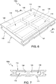
- thermoinsulating tiles 5a of the thermoinsulating coating 3 is shown in detail in figures 2-5 .
- the features described below, if not explicitly mentioned otherwise, are generally applied to all the thermoinsulating tiles 5a of the thermoinsulating coating 3.
- the thermoinsulating tile 5a comprises a thermoinsulating material body 9, which has a substantially quadrangular shape and has a first face or hot face 10 ( figures 2 and 3 ), which faces the combustion volume 4, and a second face or cold face 11 ( figures 3 and 4 ), which is opposite the hot face 10 and is oriented towards the casing 2.
- the hot face 10 and the cold face 11 may be lightly curved, respectively concave and convex or respectively convex and concave, based on the distance of the axis from the combustion chamber 1 and on the positioning on the radially outer portion or on the radially inner portion of the casing 2.
- thermoinsulating tile 5a further has a first side 12, which is arranged upstream relative to a gas flowing direction in the combustion chamber 1, and a second side 13 downstream of the first side 12.
- Flanks 15 extend between the hot face 10 and the cold face 11 and between the first side 12 and the second side 13.
- the thermoinsulating tile 5 is substantially symmetrical relative to a longitudinal middle axis A ( figure 2 ), wherein by longitudinal the direction is meant that goes from the first side 12 to the second side 13, perpendicularly to them.
- thermoinsulating tile 5a ( figures 2-4 ) has grooves 16 along the flanks 15 and anchoring seats 17 for coupling to respective anchorages 8.
- the shape of the flanks of the thermoinsulating tile 5a basically depends on the type of anchoring system used and may change according to individual cases.
- a sealed chamber 18 is encapsulated in the thermoinsulating material body 9 between the hot face 10 and the cold face 11.
- the chamber 18 has, for example, a height H ranging from one third to two thirds of the thickness T of the thermoinsulating material body 9, which is defined by a distance between the hot face 10 and the cold face 11.
- the height H of the chamber 18 may range from one quarter to three quarters of the distance between the hot face 10 and the cold face 11.
- a greater height of the chamber and, as a consequence, a smaller thickness of the tiles may be tolerated without jeopardizing the structural integrity of the tiles.
- the chamber 18 is arranged at the centre relative to the thermoinsulating material body 9.
- the chamber 18 contains a marker substance 20 having at least one component which is in the liquid state at least at a temperature of use of the tile.
- temperature of use a temperature is meant that is established on the inside of the thermoinsulating material body 9 and, more precisely, on the inside of the chamber 18 during the operation of the machine, if necessary with the exception of a starting transient.
- the marker substance 20 has at least one component with a melting temperature lower than 1000° C.
- Temperatures within the indicated threshold include the normal temperatures of use of the tiles. In these conditions, the marker substance 20 can flow, through capillarity, through interstices with a very small width, such as cracks in the thermoinsulating tile 5a.
- the marker substance 20 is a substance that is capable of leaving a permanent mark on a body with which the marker substance 20 itself comes into contact, in particular in case of a porous material like the body 9.
- the marker substance 20 may contain a pigment or a dye, which impregnates the surface of the body 9 with which it comes into contact.
- the marker substance 20 may contain a luminescent substance.
- the marker substance 20 may contain radioactive elements.
- the marker substance 20 may comprise a mixture of silicon carbide powders, which remain in the solid state due to the high melting temperature (above 2000 °C), and an alloy with a melting temperature below 1000 °C.
- the marker substance 20 may comprise low-melting alloys, like tin or aluminium alloys, which have a melting temperature below 250° C. At the operating temperatures of the gas turbine, the low-melting alloy is in the liquid state and can flow, through capillarity, through the smallest cracks extending up to the chamber 18. The liquid low-melting alloy, by flowing out of the chamber 18, carries with it the silicon carbide powders, which have dark colour, up to the surface of the thermoinsulating tile 5a, where the optical detection can easily be carried out.
- the low-melting alloy basically fulfils the function of a carrier and is present in a proportion that is sufficient to ensure the transportation of the silicon carbide powders.
- the marker substance 20 may contain 20% by weight of low-melting alloy and 80% by weight of silicon carbide powders.
- the chamber 18 may also contain a repairing substance, which is mixed with the marker substance.
- the repairing substance which is in the liquid state inside the chamber 18 at least at the temperature of use of the thermoinsulating tile 5a, has a composition that is such as to solidify when it comes into contact with the environment present in the combustion chamber.
- the marker substance 20 may contain aluminium alloys, which act as repairing substance.
- the aluminium present in the melted alloys when it comes into contact with the oxygen-rich environment of the combustion chamber, oxidizes forming alumina (Al 2 O 3 ).
- the alumina is similar to the material making up the thermoinsulating tiles and tends to easily alloy.
- the thermoinsulating tile 5a may be subjected to the formation of cracks, like the crack 21 shown in figures 4 and 5 .
- the crack 21 may originate from an edge of the thermoinsulating tile 5 and propagate towards the inside, until it reaches the chamber 18.
- the marker substance 20 flows out and reaches the outer surface of the thermoinsulating tile 5a.
- the cracks usually start from the hot face 10 or anyway affect it.
- the hot face 10, during the inspection phase may be observed from the inside of the combustion chamber 1, with no need to remove the thermoinsulating tile 5a, and - therefore - operators can easily detect marks of the marker substance 20.
- thermoinsulating tiles 5a may be carried out by an operator through direct observation or with the aid of detection tools. Direct observation may be sufficient and, in some cases, easier when the marker substance 20 contains a dye reflecting in the visible range.
- image capturing and processing tools may be conveniently used in order to search for marks of the marker substance 20.
- a digital image sensor coupled to a processing unit may be used, which allows not only to display the images detected, but also to manipulate them in order to highlight significant features.
- the direct inspection or the inspection carried out with the aid of detection tools can also use a light source with an emission spectrum selected so as to excite the luminescent substance.
- the marker substance 20 contains radioactive elements
- a radiation detector can be used.
- the repairing substance mixed with the marker substance 20 solidifies upon contact with the environment of the combustion chamber, when it flows out of the chamber 18.
- the repairing substance seals the crack, thus preventing it from propagating, and - furthermore - improves the mechanical resistance of the damaged thermoinsulating tile 5a, hence reducing the risk of detachment of parts thereof before the next maintenance intervention.
- a tile 105a comprises a body 109, where a plurality of sealed chambers 118 are encapsulated between a hot face 110 and a cold face 111.
- the chambers 118 contain a marker substance 120 of the type described above, if necessary mixed with a repairing substance.
- the marker substance 120 may be the same for all chambers 118.
- each chamber 118 may contain a respective marker substance 120.
- the chambers 118 occupy an approximately parallelepiped-shaped region extending - height-wise - between one third and two thirds of the thickness of the body 109.
- the chambers 118 are separated by walls 121 of thermoinsulating material, which define stiffening ribs and improve the mechanical resistance of the thermoinsulating tile 105a.
Landscapes
- Engineering & Computer Science (AREA)
- Chemical & Material Sciences (AREA)
- Combustion & Propulsion (AREA)
- Mechanical Engineering (AREA)
- General Engineering & Computer Science (AREA)
- Ceramic Engineering (AREA)
- Turbine Rotor Nozzle Sealing (AREA)
- Furnace Housings, Linings, Walls, And Ceilings (AREA)
- Thermal Insulation (AREA)
Claims (14)
- Wärmeisolierende Kachel für eine Brennkammer einer Gasturbine, die Folgendes umfasst:einen Körper aus wärmeisolierendem Material (9; 109), der eine erste Fläche (10; 110) und eine zweite Fläche (11; 111) besitzt;eine abgedichtete Kammer (18; 118), die im Körper aus wärmeisolierendem Material (9; 109) zwischen der ersten Fläche (10; 110) und der zweiten Fläche (11; 111) gekapselt ist und eine Markierungssubstanz (20; 120) enthält, die mindestens eine Komponente besitzt, die mindestens bei einer Verwendungstemperatur der wärmeisolierenden Kachel im flüssigen Zustand ist.
- Kachel nach Anspruch 1, wobei die Markierungssubstanz (20; 120) eine Schmelztemperatur besitzt, die niedriger als 1000 °C ist.
- Kachel nach Anspruch 1 oder 2, wobei die Markierungssubstanz (20; 120) eine Metalllegierung mit einer Schmelztemperatur, die niedriger als 1000 °C ist, und ein Siliziumkarbidpulver enthält.
- Kachel nach einem der vorhergehenden Ansprüche, wobei die Markierungssubstanz (20; 120) einen Farbstoff enthält.
- Kachel nach einem der vorhergehenden Ansprüche, wobei die Markierungssubstanz (20; 120) eine lumineszente Substanz enthält.
- Kachel nach einem der vorhergehenden Ansprüche, wobei die Markierungssubstanz (20; 120) radioaktive Elemente enthält.
- Kachel nach einem der vorhergehenden Ansprüche, wobei die abgedichtete Kammer (18; 118) eine Reparatursubstanz enthält, die sich mindestens bei der Verwendungstemperatur der Kachel in der abgedichteten Kammer (18; 118) im flüssigen Zustand befindet und sich in Kontakt mit einer Umgebung in der Kammer verfestigt.
- Kachel nach Anspruch 7, wobei die Markierungssubstanz (20; 120) Aluminium enthält.
- Kachel nach einem der vorhergehenden Ansprüche, wobei der Körper aus wärmeisolierendem Material (9; 109) eine Dicke (T) besitzt, die durch einen Abstand zwischen der ersten Fläche (10; 110) und der zweiten Fläche (11; 111) definiert ist, und die abgedichtete Kammer (18; 118) eine Höhe (H) zwischen einem Viertel und drei Vierteln der Dicke (T) des Körpers aus wärmeisolierendem Material (9; 109) besitzt.
- Kachel nach einem der vorhergehenden Ansprüche, wobei die abgedichtete Kammer (18; 118) in Bezug auf den Körper aus wärmeisolierendem Material (9; 109) mittig angeordnet ist.
- Kachel nach einem der vorhergehenden Ansprüche, die mehrere abgedichtete Kammern (118) enthält, die im Körper aus wärmeisolierendem Material (109) zwischen der ersten Fläche (110) und der zweiten Fläche (111) angeordnet sind und die entsprechende Markierungssubstanz (120) enthalten.
- Kachel nach Anspruch 11, wobei die abgedichteten Kammern (118) durch Wände (121) aus wärmeisolierendem Material, die Versteifungsstege bilden, getrennt sind.
- Brennkammer einer Gasturbine, die eine wärmeisolierende Beschichtung (3) umfasst, die mindestens eine wärmeisolierende Kachel (5a) nach einem der vorhergehenden Ansprüche besitzt.
- Brennkammer nach Anspruch 13, die mehrere wärmeisolierende Kacheln (5a) umfasst, die in einem Bereich angeordnet sind, in dem ein Beschädigungsrisiko der wärmeisolierenden Kacheln statistisch größer ist.
Applications Claiming Priority (1)
| Application Number | Priority Date | Filing Date | Title |
|---|---|---|---|
| IT102016000130851A IT201600130851A1 (it) | 2016-12-23 | 2016-12-23 | Piastrella termoisolante per camere di combustione di turbine a gas |
Publications (2)
| Publication Number | Publication Date |
|---|---|
| EP3339737A1 EP3339737A1 (de) | 2018-06-27 |
| EP3339737B1 true EP3339737B1 (de) | 2019-10-23 |
Family
ID=58670218
Family Applications (1)
| Application Number | Title | Priority Date | Filing Date |
|---|---|---|---|
| EP17209153.0A Active EP3339737B1 (de) | 2016-12-23 | 2017-12-20 | Wärmeisolierende kachel für eine brennkammer einer gasturbine |
Country Status (4)
| Country | Link |
|---|---|
| US (1) | US10808931B2 (de) |
| EP (1) | EP3339737B1 (de) |
| CN (1) | CN108240638B (de) |
| IT (1) | IT201600130851A1 (de) |
Families Citing this family (1)
| Publication number | Priority date | Publication date | Assignee | Title |
|---|---|---|---|---|
| US12313261B1 (en) * | 2024-04-05 | 2025-05-27 | Rtx Corporation | Combustor liner panels |
Citations (1)
| Publication number | Priority date | Publication date | Assignee | Title |
|---|---|---|---|---|
| EP0943867A1 (de) * | 1998-03-17 | 1999-09-22 | Abb Research Ltd. | Keramische Auskleidung einer Brennkammer |
Family Cites Families (17)
| Publication number | Priority date | Publication date | Assignee | Title |
|---|---|---|---|---|
| US3797896A (en) * | 1971-04-21 | 1974-03-19 | Avco Corp | Bearing for wear detection |
| US4604604A (en) * | 1984-06-29 | 1986-08-05 | International Harvester Company | Vapor emitting wear indicator |
| US4838030A (en) * | 1987-08-06 | 1989-06-13 | Avco Corporation | Combustion chamber liner having failure activated cooling and dectection system |
| US6527849B2 (en) * | 1990-06-19 | 2003-03-04 | Carolyn M. Dry | Self-repairing, reinforced matrix materials |
| US5451110A (en) * | 1993-12-28 | 1995-09-19 | Syedala Industries, Inc. | Bearing wear indicator |
| FR2732338B1 (fr) * | 1995-03-28 | 1997-06-13 | Europ Propulsion | Materiau composite protege contre l'oxydation par matrice auto-cicatrisante et son procede de fabrication |
| EP1105550B1 (de) * | 1998-07-27 | 2003-03-12 | Imperial College Of Science, Technology & Medicine | Wärmedämmschicht mit eingebettetem thermolumineszenz-indikatorwerkstoff |
| CN1836152A (zh) * | 2003-08-13 | 2006-09-20 | 西门子公司 | 至少一个隔热层在一个基体上的结构 |
| US7334330B2 (en) * | 2004-04-28 | 2008-02-26 | Siemens Power Generation, Inc. | Thermally insulating layer incorporating a distinguishing agent and method for inspecting the same |
| US20090162533A1 (en) * | 2007-12-19 | 2009-06-25 | Glen Harold Kirby | Methods allowing for improved inspection of components having a barrier coating |
| US8490474B2 (en) * | 2010-12-30 | 2013-07-23 | General Electric Company | Methods, systems and apparatus for detecting material defects in combustors of combustion turbine engines |
| US9534783B2 (en) * | 2011-07-21 | 2017-01-03 | United Technologies Corporation | Insert adjacent to a heat shield element for a gas turbine engine combustor |
| EP2698503A1 (de) * | 2012-08-17 | 2014-02-19 | Siemens Aktiengesellschaft | Turbomaschinenkomponentenkennzeichnung |
| CN105324611A (zh) * | 2013-05-21 | 2016-02-10 | 西门子股份公司 | 用于燃烧室的隔热件的隔热瓦 |
| FR3007028B1 (fr) * | 2013-06-13 | 2015-07-03 | Herakles | Barriere environnementale pour substrat refractaire contenant du silicium |
| US9804058B2 (en) * | 2014-02-27 | 2017-10-31 | Pratt & Whitney Canada Corp. | Method of facilitating visual detection of a crack in a component of a gas turbine engine |
| US9938839B2 (en) * | 2014-03-14 | 2018-04-10 | General Electric Company | Articles having reduced expansion and hermetic environmental barrier coatings and methods for their manufacture |
-
2016
- 2016-12-23 IT IT102016000130851A patent/IT201600130851A1/it unknown
-
2017
- 2017-12-20 EP EP17209153.0A patent/EP3339737B1/de active Active
- 2017-12-22 CN CN201711406727.XA patent/CN108240638B/zh active Active
- 2017-12-22 US US15/852,520 patent/US10808931B2/en active Active
Patent Citations (1)
| Publication number | Priority date | Publication date | Assignee | Title |
|---|---|---|---|---|
| EP0943867A1 (de) * | 1998-03-17 | 1999-09-22 | Abb Research Ltd. | Keramische Auskleidung einer Brennkammer |
Also Published As
| Publication number | Publication date |
|---|---|
| IT201600130851A1 (it) | 2018-06-23 |
| US20180179958A1 (en) | 2018-06-28 |
| US10808931B2 (en) | 2020-10-20 |
| EP3339737A1 (de) | 2018-06-27 |
| CN108240638B (zh) | 2022-07-08 |
| CN108240638A (zh) | 2018-07-03 |
Similar Documents
| Publication | Publication Date | Title |
|---|---|---|
| US11504813B2 (en) | Methods for health monitoring of ceramic matrix composite components in gas turbine engines | |
| US8753073B2 (en) | Turbine shroud sealing apparatus | |
| US20190040758A1 (en) | Turbine ring assembly with axial retention | |
| US4322945A (en) | Fuel nozzle guide heat shield for a gas turbine engine | |
| JP5977820B2 (ja) | はめ込み型の温度および/またはひずみのセンサ用の方法およびシステム | |
| US10544698B2 (en) | Air seal abrasive coating and method | |
| JP6158330B2 (ja) | ターボ機械コンポーネントマーキング | |
| US20170165708A1 (en) | Coating inspection method | |
| US20180073398A1 (en) | Turbine ring assembly made from ceramic matrix composite material | |
| US20170167264A1 (en) | Turbine rotor for a gas turbine engine | |
| EP2402557B1 (de) | Turbinenrotoranordnung | |
| US6200088B1 (en) | On-line monitor for detecting excessive temperatures of critical components of a turbine | |
| US20180142572A1 (en) | A turbine ring assembly held by jaw coupling | |
| EP3339737B1 (de) | Wärmeisolierende kachel für eine brennkammer einer gasturbine | |
| US20160201912A1 (en) | Wedge-shaped ceramic heat shield of a gas turbine combustion chamber | |
| CA2928435A1 (en) | Aircraft engine strut with integrated sensor component | |
| CA2857818C (en) | Wall construction for gaspath traversing component | |
| US20160047264A1 (en) | Blade outer air seal having partial coating | |
| JP2008169833A (ja) | ガスタービンエンジン内の温度過昇状態を防止する方法 | |
| EP2917503A2 (de) | Einlaufbeschichtungssystem für eine turbinenschaufel und zugehörige turbinenblätter | |
| RS54052B1 (sr) | Indikator habanja u kompozitnom sistemu od vatrostalnih keramičkih opeka | |
| US9488069B2 (en) | Cooling-air guidance in a housing structure of a turbomachine | |
| EP3117147B1 (de) | Brennkammer einer gasturbinenanlage | |
| EP2984472B1 (de) | Verfahren zur erkennung einer beschädigten komponente | |
| US20070000252A1 (en) | Heat shield block for lining a combustion chamber wall, combustion chamber and gas turbine |
Legal Events
| Date | Code | Title | Description |
|---|---|---|---|
| PUAI | Public reference made under article 153(3) epc to a published international application that has entered the european phase |
Free format text: ORIGINAL CODE: 0009012 |
|
| STAA | Information on the status of an ep patent application or granted ep patent |
Free format text: STATUS: THE APPLICATION HAS BEEN PUBLISHED |
|
| AK | Designated contracting states |
Kind code of ref document: A1 Designated state(s): AL AT BE BG CH CY CZ DE DK EE ES FI FR GB GR HR HU IE IS IT LI LT LU LV MC MK MT NL NO PL PT RO RS SE SI SK SM TR |
|
| AX | Request for extension of the european patent |
Extension state: BA ME |
|
| STAA | Information on the status of an ep patent application or granted ep patent |
Free format text: STATUS: REQUEST FOR EXAMINATION WAS MADE |
|
| 17P | Request for examination filed |
Effective date: 20181227 |
|
| RBV | Designated contracting states (corrected) |
Designated state(s): AL AT BE BG CH CY CZ DE DK EE ES FI FR GB GR HR HU IE IS IT LI LT LU LV MC MK MT NL NO PL PT RO RS SE SI SK SM TR |
|
| GRAP | Despatch of communication of intention to grant a patent |
Free format text: ORIGINAL CODE: EPIDOSNIGR1 |
|
| STAA | Information on the status of an ep patent application or granted ep patent |
Free format text: STATUS: GRANT OF PATENT IS INTENDED |
|
| RIC1 | Information provided on ipc code assigned before grant |
Ipc: F23R 3/00 20060101AFI20190417BHEP Ipc: B23P 6/04 20060101ALI20190417BHEP Ipc: F02C 7/24 20060101ALI20190417BHEP Ipc: F23M 5/02 20060101ALI20190417BHEP Ipc: C04B 41/85 20060101ALI20190417BHEP |
|
| INTG | Intention to grant announced |
Effective date: 20190514 |
|
| GRAS | Grant fee paid |
Free format text: ORIGINAL CODE: EPIDOSNIGR3 |
|
| GRAA | (expected) grant |
Free format text: ORIGINAL CODE: 0009210 |
|
| STAA | Information on the status of an ep patent application or granted ep patent |
Free format text: STATUS: THE PATENT HAS BEEN GRANTED |
|
| AK | Designated contracting states |
Kind code of ref document: B1 Designated state(s): AL AT BE BG CH CY CZ DE DK EE ES FI FR GB GR HR HU IE IS IT LI LT LU LV MC MK MT NL NO PL PT RO RS SE SI SK SM TR |
|
| REG | Reference to a national code |
Ref country code: GB Ref legal event code: FG4D |
|
| REG | Reference to a national code |
Ref country code: CH Ref legal event code: EP |
|
| REG | Reference to a national code |
Ref country code: IE Ref legal event code: FG4D |
|
| REG | Reference to a national code |
Ref country code: DE Ref legal event code: R096 Ref document number: 602017008053 Country of ref document: DE |
|
| REG | Reference to a national code |
Ref country code: AT Ref legal event code: REF Ref document number: 1194064 Country of ref document: AT Kind code of ref document: T Effective date: 20191115 |
|
| REG | Reference to a national code |
Ref country code: NL Ref legal event code: MP Effective date: 20191023 |
|
| REG | Reference to a national code |
Ref country code: LT Ref legal event code: MG4D |
|
| PG25 | Lapsed in a contracting state [announced via postgrant information from national office to epo] |
Ref country code: GR Free format text: LAPSE BECAUSE OF FAILURE TO SUBMIT A TRANSLATION OF THE DESCRIPTION OR TO PAY THE FEE WITHIN THE PRESCRIBED TIME-LIMIT Effective date: 20200124 Ref country code: LT Free format text: LAPSE BECAUSE OF FAILURE TO SUBMIT A TRANSLATION OF THE DESCRIPTION OR TO PAY THE FEE WITHIN THE PRESCRIBED TIME-LIMIT Effective date: 20191023 Ref country code: NL Free format text: LAPSE BECAUSE OF FAILURE TO SUBMIT A TRANSLATION OF THE DESCRIPTION OR TO PAY THE FEE WITHIN THE PRESCRIBED TIME-LIMIT Effective date: 20191023 Ref country code: PL Free format text: LAPSE BECAUSE OF FAILURE TO SUBMIT A TRANSLATION OF THE DESCRIPTION OR TO PAY THE FEE WITHIN THE PRESCRIBED TIME-LIMIT Effective date: 20191023 Ref country code: SE Free format text: LAPSE BECAUSE OF FAILURE TO SUBMIT A TRANSLATION OF THE DESCRIPTION OR TO PAY THE FEE WITHIN THE PRESCRIBED TIME-LIMIT Effective date: 20191023 Ref country code: LV Free format text: LAPSE BECAUSE OF FAILURE TO SUBMIT A TRANSLATION OF THE DESCRIPTION OR TO PAY THE FEE WITHIN THE PRESCRIBED TIME-LIMIT Effective date: 20191023 Ref country code: NO Free format text: LAPSE BECAUSE OF FAILURE TO SUBMIT A TRANSLATION OF THE DESCRIPTION OR TO PAY THE FEE WITHIN THE PRESCRIBED TIME-LIMIT Effective date: 20200123 Ref country code: FI Free format text: LAPSE BECAUSE OF FAILURE TO SUBMIT A TRANSLATION OF THE DESCRIPTION OR TO PAY THE FEE WITHIN THE PRESCRIBED TIME-LIMIT Effective date: 20191023 Ref country code: BG Free format text: LAPSE BECAUSE OF FAILURE TO SUBMIT A TRANSLATION OF THE DESCRIPTION OR TO PAY THE FEE WITHIN THE PRESCRIBED TIME-LIMIT Effective date: 20200123 Ref country code: PT Free format text: LAPSE BECAUSE OF FAILURE TO SUBMIT A TRANSLATION OF THE DESCRIPTION OR TO PAY THE FEE WITHIN THE PRESCRIBED TIME-LIMIT Effective date: 20200224 |
|
| PG25 | Lapsed in a contracting state [announced via postgrant information from national office to epo] |
Ref country code: RS Free format text: LAPSE BECAUSE OF FAILURE TO SUBMIT A TRANSLATION OF THE DESCRIPTION OR TO PAY THE FEE WITHIN THE PRESCRIBED TIME-LIMIT Effective date: 20191023 Ref country code: IS Free format text: LAPSE BECAUSE OF FAILURE TO SUBMIT A TRANSLATION OF THE DESCRIPTION OR TO PAY THE FEE WITHIN THE PRESCRIBED TIME-LIMIT Effective date: 20200224 Ref country code: HR Free format text: LAPSE BECAUSE OF FAILURE TO SUBMIT A TRANSLATION OF THE DESCRIPTION OR TO PAY THE FEE WITHIN THE PRESCRIBED TIME-LIMIT Effective date: 20191023 |
|
| PG25 | Lapsed in a contracting state [announced via postgrant information from national office to epo] |
Ref country code: AL Free format text: LAPSE BECAUSE OF FAILURE TO SUBMIT A TRANSLATION OF THE DESCRIPTION OR TO PAY THE FEE WITHIN THE PRESCRIBED TIME-LIMIT Effective date: 20191023 |
|
| REG | Reference to a national code |
Ref country code: DE Ref legal event code: R097 Ref document number: 602017008053 Country of ref document: DE |
|
| PG2D | Information on lapse in contracting state deleted |
Ref country code: IS |
|
| PG25 | Lapsed in a contracting state [announced via postgrant information from national office to epo] |
Ref country code: EE Free format text: LAPSE BECAUSE OF FAILURE TO SUBMIT A TRANSLATION OF THE DESCRIPTION OR TO PAY THE FEE WITHIN THE PRESCRIBED TIME-LIMIT Effective date: 20191023 Ref country code: DK Free format text: LAPSE BECAUSE OF FAILURE TO SUBMIT A TRANSLATION OF THE DESCRIPTION OR TO PAY THE FEE WITHIN THE PRESCRIBED TIME-LIMIT Effective date: 20191023 Ref country code: ES Free format text: LAPSE BECAUSE OF FAILURE TO SUBMIT A TRANSLATION OF THE DESCRIPTION OR TO PAY THE FEE WITHIN THE PRESCRIBED TIME-LIMIT Effective date: 20191023 Ref country code: CZ Free format text: LAPSE BECAUSE OF FAILURE TO SUBMIT A TRANSLATION OF THE DESCRIPTION OR TO PAY THE FEE WITHIN THE PRESCRIBED TIME-LIMIT Effective date: 20191023 Ref country code: RO Free format text: LAPSE BECAUSE OF FAILURE TO SUBMIT A TRANSLATION OF THE DESCRIPTION OR TO PAY THE FEE WITHIN THE PRESCRIBED TIME-LIMIT Effective date: 20191023 Ref country code: IS Free format text: LAPSE BECAUSE OF FAILURE TO SUBMIT A TRANSLATION OF THE DESCRIPTION OR TO PAY THE FEE WITHIN THE PRESCRIBED TIME-LIMIT Effective date: 20200223 |
|
| REG | Reference to a national code |
Ref country code: AT Ref legal event code: MK05 Ref document number: 1194064 Country of ref document: AT Kind code of ref document: T Effective date: 20191023 |
|
| REG | Reference to a national code |
Ref country code: BE Ref legal event code: MM Effective date: 20191231 |
|
| PLBE | No opposition filed within time limit |
Free format text: ORIGINAL CODE: 0009261 |
|
| STAA | Information on the status of an ep patent application or granted ep patent |
Free format text: STATUS: NO OPPOSITION FILED WITHIN TIME LIMIT |
|
| PG25 | Lapsed in a contracting state [announced via postgrant information from national office to epo] |
Ref country code: SM Free format text: LAPSE BECAUSE OF FAILURE TO SUBMIT A TRANSLATION OF THE DESCRIPTION OR TO PAY THE FEE WITHIN THE PRESCRIBED TIME-LIMIT Effective date: 20191023 Ref country code: MC Free format text: LAPSE BECAUSE OF FAILURE TO SUBMIT A TRANSLATION OF THE DESCRIPTION OR TO PAY THE FEE WITHIN THE PRESCRIBED TIME-LIMIT Effective date: 20191023 Ref country code: SK Free format text: LAPSE BECAUSE OF FAILURE TO SUBMIT A TRANSLATION OF THE DESCRIPTION OR TO PAY THE FEE WITHIN THE PRESCRIBED TIME-LIMIT Effective date: 20191023 Ref country code: IT Free format text: LAPSE BECAUSE OF FAILURE TO SUBMIT A TRANSLATION OF THE DESCRIPTION OR TO PAY THE FEE WITHIN THE PRESCRIBED TIME-LIMIT Effective date: 20191023 |
|
| 26N | No opposition filed |
Effective date: 20200724 |
|
| PG25 | Lapsed in a contracting state [announced via postgrant information from national office to epo] |
Ref country code: IE Free format text: LAPSE BECAUSE OF NON-PAYMENT OF DUE FEES Effective date: 20191220 Ref country code: LU Free format text: LAPSE BECAUSE OF NON-PAYMENT OF DUE FEES Effective date: 20191220 Ref country code: FR Free format text: LAPSE BECAUSE OF NON-PAYMENT OF DUE FEES Effective date: 20191223 |
|
| PG25 | Lapsed in a contracting state [announced via postgrant information from national office to epo] |
Ref country code: SI Free format text: LAPSE BECAUSE OF FAILURE TO SUBMIT A TRANSLATION OF THE DESCRIPTION OR TO PAY THE FEE WITHIN THE PRESCRIBED TIME-LIMIT Effective date: 20191023 Ref country code: BE Free format text: LAPSE BECAUSE OF NON-PAYMENT OF DUE FEES Effective date: 20191231 Ref country code: AT Free format text: LAPSE BECAUSE OF FAILURE TO SUBMIT A TRANSLATION OF THE DESCRIPTION OR TO PAY THE FEE WITHIN THE PRESCRIBED TIME-LIMIT Effective date: 20191023 |
|
| PG25 | Lapsed in a contracting state [announced via postgrant information from national office to epo] |
Ref country code: CY Free format text: LAPSE BECAUSE OF FAILURE TO SUBMIT A TRANSLATION OF THE DESCRIPTION OR TO PAY THE FEE WITHIN THE PRESCRIBED TIME-LIMIT Effective date: 20191023 |
|
| PG25 | Lapsed in a contracting state [announced via postgrant information from national office to epo] |
Ref country code: MT Free format text: LAPSE BECAUSE OF FAILURE TO SUBMIT A TRANSLATION OF THE DESCRIPTION OR TO PAY THE FEE WITHIN THE PRESCRIBED TIME-LIMIT Effective date: 20191023 Ref country code: HU Free format text: LAPSE BECAUSE OF FAILURE TO SUBMIT A TRANSLATION OF THE DESCRIPTION OR TO PAY THE FEE WITHIN THE PRESCRIBED TIME-LIMIT; INVALID AB INITIO Effective date: 20171220 |
|
| REG | Reference to a national code |
Ref country code: CH Ref legal event code: PL |
|
| PG25 | Lapsed in a contracting state [announced via postgrant information from national office to epo] |
Ref country code: CH Free format text: LAPSE BECAUSE OF NON-PAYMENT OF DUE FEES Effective date: 20201231 Ref country code: LI Free format text: LAPSE BECAUSE OF NON-PAYMENT OF DUE FEES Effective date: 20201231 |
|
| PG25 | Lapsed in a contracting state [announced via postgrant information from national office to epo] |
Ref country code: TR Free format text: LAPSE BECAUSE OF FAILURE TO SUBMIT A TRANSLATION OF THE DESCRIPTION OR TO PAY THE FEE WITHIN THE PRESCRIBED TIME-LIMIT Effective date: 20191023 |
|
| PG25 | Lapsed in a contracting state [announced via postgrant information from national office to epo] |
Ref country code: MK Free format text: LAPSE BECAUSE OF FAILURE TO SUBMIT A TRANSLATION OF THE DESCRIPTION OR TO PAY THE FEE WITHIN THE PRESCRIBED TIME-LIMIT Effective date: 20191023 |
|
| GBPC | Gb: european patent ceased through non-payment of renewal fee |
Effective date: 20211220 |
|
| PG25 | Lapsed in a contracting state [announced via postgrant information from national office to epo] |
Ref country code: GB Free format text: LAPSE BECAUSE OF NON-PAYMENT OF DUE FEES Effective date: 20211220 |
|
| P01 | Opt-out of the competence of the unified patent court (upc) registered |
Effective date: 20240430 |
|
| PGFP | Annual fee paid to national office [announced via postgrant information from national office to epo] |
Ref country code: DE Payment date: 20251222 Year of fee payment: 9 |