EP3339693A1 - Sealing apparatus - Google Patents
Sealing apparatus Download PDFInfo
- Publication number
- EP3339693A1 EP3339693A1 EP16853396.6A EP16853396A EP3339693A1 EP 3339693 A1 EP3339693 A1 EP 3339693A1 EP 16853396 A EP16853396 A EP 16853396A EP 3339693 A1 EP3339693 A1 EP 3339693A1
- Authority
- EP
- European Patent Office
- Prior art keywords
- periphery side
- outer periphery
- sealing apparatus
- lip
- slinger
- Prior art date
- Legal status (The legal status is an assumption and is not a legal conclusion. Google has not performed a legal analysis and makes no representation as to the accuracy of the status listed.)
- Granted
Links
Images



Classifications
-
- F—MECHANICAL ENGINEERING; LIGHTING; HEATING; WEAPONS; BLASTING
- F16—ENGINEERING ELEMENTS AND UNITS; GENERAL MEASURES FOR PRODUCING AND MAINTAINING EFFECTIVE FUNCTIONING OF MACHINES OR INSTALLATIONS; THERMAL INSULATION IN GENERAL
- F16C—SHAFTS; FLEXIBLE SHAFTS; ELEMENTS OR CRANKSHAFT MECHANISMS; ROTARY BODIES OTHER THAN GEARING ELEMENTS; BEARINGS
- F16C33/00—Parts of bearings; Special methods for making bearings or parts thereof
- F16C33/72—Sealings
- F16C33/76—Sealings of ball or roller bearings
- F16C33/80—Labyrinth sealings
- F16C33/805—Labyrinth sealings in addition to other sealings, e.g. dirt guards to protect sealings with sealing lips
-
- F—MECHANICAL ENGINEERING; LIGHTING; HEATING; WEAPONS; BLASTING
- F16—ENGINEERING ELEMENTS AND UNITS; GENERAL MEASURES FOR PRODUCING AND MAINTAINING EFFECTIVE FUNCTIONING OF MACHINES OR INSTALLATIONS; THERMAL INSULATION IN GENERAL
- F16C—SHAFTS; FLEXIBLE SHAFTS; ELEMENTS OR CRANKSHAFT MECHANISMS; ROTARY BODIES OTHER THAN GEARING ELEMENTS; BEARINGS
- F16C19/00—Bearings with rolling contact, for exclusively rotary movement
- F16C19/02—Bearings with rolling contact, for exclusively rotary movement with bearing balls essentially of the same size in one or more circular rows
- F16C19/14—Bearings with rolling contact, for exclusively rotary movement with bearing balls essentially of the same size in one or more circular rows for both radial and axial load
- F16C19/18—Bearings with rolling contact, for exclusively rotary movement with bearing balls essentially of the same size in one or more circular rows for both radial and axial load with two or more rows of balls
- F16C19/181—Bearings with rolling contact, for exclusively rotary movement with bearing balls essentially of the same size in one or more circular rows for both radial and axial load with two or more rows of balls with angular contact
- F16C19/183—Bearings with rolling contact, for exclusively rotary movement with bearing balls essentially of the same size in one or more circular rows for both radial and axial load with two or more rows of balls with angular contact with two rows at opposite angles
- F16C19/184—Bearings with rolling contact, for exclusively rotary movement with bearing balls essentially of the same size in one or more circular rows for both radial and axial load with two or more rows of balls with angular contact with two rows at opposite angles in O-arrangement
- F16C19/186—Bearings with rolling contact, for exclusively rotary movement with bearing balls essentially of the same size in one or more circular rows for both radial and axial load with two or more rows of balls with angular contact with two rows at opposite angles in O-arrangement with three raceways provided integrally on parts other than race rings, e.g. third generation hubs
-
- F—MECHANICAL ENGINEERING; LIGHTING; HEATING; WEAPONS; BLASTING
- F16—ENGINEERING ELEMENTS AND UNITS; GENERAL MEASURES FOR PRODUCING AND MAINTAINING EFFECTIVE FUNCTIONING OF MACHINES OR INSTALLATIONS; THERMAL INSULATION IN GENERAL
- F16C—SHAFTS; FLEXIBLE SHAFTS; ELEMENTS OR CRANKSHAFT MECHANISMS; ROTARY BODIES OTHER THAN GEARING ELEMENTS; BEARINGS
- F16C33/00—Parts of bearings; Special methods for making bearings or parts thereof
- F16C33/72—Sealings
- F16C33/76—Sealings of ball or roller bearings
- F16C33/78—Sealings of ball or roller bearings with a diaphragm, disc, or ring, with or without resilient members
- F16C33/7869—Sealings of ball or roller bearings with a diaphragm, disc, or ring, with or without resilient members mounted with a cylindrical portion to the inner surface of the outer race and having a radial portion extending inward
- F16C33/7879—Sealings of ball or roller bearings with a diaphragm, disc, or ring, with or without resilient members mounted with a cylindrical portion to the inner surface of the outer race and having a radial portion extending inward with a further sealing ring
-
- F—MECHANICAL ENGINEERING; LIGHTING; HEATING; WEAPONS; BLASTING
- F16—ENGINEERING ELEMENTS AND UNITS; GENERAL MEASURES FOR PRODUCING AND MAINTAINING EFFECTIVE FUNCTIONING OF MACHINES OR INSTALLATIONS; THERMAL INSULATION IN GENERAL
- F16J—PISTONS; CYLINDERS; SEALINGS
- F16J15/00—Sealings
- F16J15/16—Sealings between relatively-moving surfaces
- F16J15/164—Sealings between relatively-moving surfaces the sealing action depending on movements; pressure difference, temperature or presence of leaking fluid
-
- F—MECHANICAL ENGINEERING; LIGHTING; HEATING; WEAPONS; BLASTING
- F16—ENGINEERING ELEMENTS AND UNITS; GENERAL MEASURES FOR PRODUCING AND MAINTAINING EFFECTIVE FUNCTIONING OF MACHINES OR INSTALLATIONS; THERMAL INSULATION IN GENERAL
- F16J—PISTONS; CYLINDERS; SEALINGS
- F16J15/00—Sealings
- F16J15/16—Sealings between relatively-moving surfaces
- F16J15/32—Sealings between relatively-moving surfaces with elastic sealings, e.g. O-rings
- F16J15/3204—Sealings between relatively-moving surfaces with elastic sealings, e.g. O-rings with at least one lip
- F16J15/3232—Sealings between relatively-moving surfaces with elastic sealings, e.g. O-rings with at least one lip having two or more lips
-
- F—MECHANICAL ENGINEERING; LIGHTING; HEATING; WEAPONS; BLASTING
- F16—ENGINEERING ELEMENTS AND UNITS; GENERAL MEASURES FOR PRODUCING AND MAINTAINING EFFECTIVE FUNCTIONING OF MACHINES OR INSTALLATIONS; THERMAL INSULATION IN GENERAL
- F16J—PISTONS; CYLINDERS; SEALINGS
- F16J15/00—Sealings
- F16J15/16—Sealings between relatively-moving surfaces
- F16J15/32—Sealings between relatively-moving surfaces with elastic sealings, e.g. O-rings
- F16J15/3248—Sealings between relatively-moving surfaces with elastic sealings, e.g. O-rings provided with casings or supports
- F16J15/3252—Sealings between relatively-moving surfaces with elastic sealings, e.g. O-rings provided with casings or supports with rigid casings or supports
- F16J15/3256—Sealings between relatively-moving surfaces with elastic sealings, e.g. O-rings provided with casings or supports with rigid casings or supports comprising two casing or support elements, one attached to each surface, e.g. cartridge or cassette seals
- F16J15/3264—Sealings between relatively-moving surfaces with elastic sealings, e.g. O-rings provided with casings or supports with rigid casings or supports comprising two casing or support elements, one attached to each surface, e.g. cartridge or cassette seals the elements being separable from each other
-
- F—MECHANICAL ENGINEERING; LIGHTING; HEATING; WEAPONS; BLASTING
- F16—ENGINEERING ELEMENTS AND UNITS; GENERAL MEASURES FOR PRODUCING AND MAINTAINING EFFECTIVE FUNCTIONING OF MACHINES OR INSTALLATIONS; THERMAL INSULATION IN GENERAL
- F16C—SHAFTS; FLEXIBLE SHAFTS; ELEMENTS OR CRANKSHAFT MECHANISMS; ROTARY BODIES OTHER THAN GEARING ELEMENTS; BEARINGS
- F16C2326/00—Articles relating to transporting
- F16C2326/01—Parts of vehicles in general
- F16C2326/02—Wheel hubs or castors
Definitions
- the present invention relates to a sealing apparatus, and particularly relates to a sealing apparatus used in a hub bearing of a vehicle or the like.
- a hub bearing that rotatably supports a wheel is placed in an environment directly exposed to foreign matter such as rainwater, muddy water, and dust.
- a sealing apparatus has been attached to the hub bearing to seal the inside of the hub bearing.
- the sealing apparatus is adapted to seal lubricant in the hub bearing and prevent the foreign matter from entering the inside of the hub bearing.
- a sealing apparatus used in a hub bearing is required to prevent a torque resistance applied by the sealing apparatus to the hub bearing from being increased while preventing the foreign matter from entering the inside of the hub bearing.
- Fig. 4 is a partial sectional diagram illustrating a schematic configuration of a conventional sealing apparatus attached to a hub bearing (hereinafter referred to as a "hub seal").
- a sealing apparatus 100 serving as a conventional hub seal is press-fitted between an outer ring 201 and a hub ring 202 to seal a space 203 in an annular shape between the outer ring 201 and the hub ring 202 that are mutually relatively rotated about the same axis.
- the sealing apparatus 100 is adapted to suppress leakage of lubricant of a rolling element 204 filled in the space 203 and suppress the foreign matter from entering the space 203.
- the sealing apparatus 100 includes a reinforcing ring 111 made of metal that is fitted to an inner peripheral surface of the outer ring 201 of the hub bearing 200, and an elastic body part 112 made of a rubber material that is integrally formed with the reinforcing ring 111 to cover the reinforcing ring 111.
- the elastic body part 112 has side lips 115, 116, and a radial lip 117, and the side lips 115, 116 and the radial lip 117 are slidably brought into contact with a curved peripheral surface 202a of the hub ring 202.
- the side lips 115,116 and the radial lip 117 are adapted to suppress the foreign matter from entering the space 203 of the hub bearing 200.
- Patent Literature 1 Japanese Patent Application Laid-Open No. 2014-240676
- the side lips 115, 116 and the radial lip 117 are adapted to prevent entrance of the foreign matter.
- the conventional sealing apparatus 100 must enhance the performance of preventing entrance of the foreign matter.
- the side lips 115, 116 that are slidably brought into contact with the curved peripheral surface 202a of the hub ring 202 are increased, as is conventional.
- the side lips 115, 116 that prevent entering of the foreign matter by being slidably brought into contact with the curved peripheral surface 202a lead to increased torque resistance of the hub bearing 200.
- the present invention has been made in view of the above problems, and it is an object of the present invention to provide a sealing apparatus that can enhance a function of preventing entrance of foreign matter while avoiding an increase in generated torque resistance.
- a sealing apparatus is a sealing apparatus sealing between an outer periphery side member in an annular shape and an inner periphery side member in an annular shape that is at least partially surrounded by the outer periphery side member in a bearing, the outer periphery side member and the inner periphery side member being mutually relatively rotatable about an axis
- the sealing apparatus being characterized by comprising: a sealing apparatus body that is to be attached to the outer periphery side member; and a slinger in an annular shape centered about the axis that is to be attached to the inner periphery side member, the slinger being positioned outside of the sealing apparatus body
- the sealing apparatus body comprises: a reinforcing ring in an annular shape centered about the axis; and an elastic body part in an annular shape centered about the axis, the elastic body being attached to the reinforcing ring and being formed from an elastic body, the elastic body part
- the elastic body part comprises a weir portion in an annular shape centered about the axis, the weir portion projecting toward the outer periphery side from an outer peripheral surface of the outer periphery side member, wherein the weir portion forms the groove portion between the outer periphery side labyrinth lip and the weir portion.
- the elastic body part at a part between the outer periphery side labyrinth lip and the inner periphery side labyrinth lip faces the slinger with a gap so as to form a labyrinth seal.
- the slinger is spaced from the inner periphery side member in the direction of the axis so as to form a grooved gap portion in an annular shape centered about the axis, the grooved gap portion being depressed toward the inner periphery side.
- a function of preventing entrance of foreign matter can be enhanced while avoiding an increase in generated torque resistance.
- Fig. 1 is a sectional diagram illustrating a schematic configuration of a sealing apparatus 1 according to the first embodiment of the present invention.
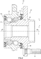
- Fig. 2 is a sectional diagram illustrating a state in which the sealing apparatus 1 according to the first embodiment of the present invention is attached to a hub bearing 50 that rotatably supports a wheel in an automobile, for example.
- the hub bearing 50 includes: an outer ring 51 in an annular shape centered about an axis x that serves as an outer periphery side member; a hub 52 in an annular shape centered about the axis x that serves as an inner periphery side member, is relatively rotatable with respect to the outer ring 51, and is partially surrounded by the outer ring 51; and a plurality of bearing balls 53 that are disposed between the outer ring 51 and the hub 52.
- the hub 52 has an inner ring 54 and a hub ring 55, and a wheel (not illustrated) is mounted on a wheel mounting flange 56 of the hub ring 55 by a plurality of hub bolts 57.
- the sealing apparatus 1 according to the first embodiment of the present invention is attached between the inner peripheral surface of the outer ring 51 of the hub bearing 50 and the outer peripheral surface of the hub ring 55 of the hub 52.
- Another sealing apparatus 60 is attached between the inner peripheral surface of the outer ring 51 and the outer peripheral surface of the inner ring 54 of the hub 52.
- the sealing apparatus 1 according to the first embodiment of the present invention instead of the other sealing apparatus 60, can be attached between the inner peripheral surface of the outer ring 51 and the outer peripheral surface of the inner ring 54.
- the sealing apparatus 1 in an annular shape centered about the axis x is disposed to seal the space 5 of the hub bearing 50.
- the sealing apparatus 1 is adapted to prevent lubricant from leaking from a region where the bearing balls 53 and the like of the hub bearing 50 are provided, and to prevent foreign matter such as rainwater, muddy water, and dust from entering the region from an external side.
- the sealing apparatus 1 includes: a sealing apparatus body 10 in an annular shape centered about the axis x; and a slinger 20 in an annular shape centered about the axis x.
- the slinger 20 is disposed outside of the sealing apparatus body 10 to face the sealing apparatus body 10.
- the sealing apparatus body 10 includes: an elastic body part 11 made of an elastic body in an annular shape centered about the axis x; and a reinforcing ring 12 made of metal in an annular shape centered about the axis x.
- the elastic body part 11 is integrally attached to the reinforcing ring 12.
- the elastic body of the elastic body part 11 include various rubber materials.
- the rubber materials include synthetic rubbers such as nitrile rubber (NBR), hydrogenated nitrile rubber (H-NBR), acrylic rubber (ACM), or fluorine rubber (FKM).
- the metal materials of the reinforcing ring 12 include stainless steel or SPCC (cold rolled steel sheet).
- the term “outer side” refers to a direction of arrow a in a direction of the axis x
- the term “inner side” refers to a direction of arrow b in the direction of the axis x, as illustrated in Fig. 1 .
- the outer side refers to a side in a direction facing an external side of the hub bearing 50, or a side in a direction facing an atmospheric side where the foreign matter is present.
- the inner side refers to a side in a direction facing an interior side of the hub bearing 50, or a side in a direction facing the space 5.
- outer periphery side refers to a direction away from the axis x (direction of arrow c in Fig. 1 ), and the term “inner periphery side” refers to a direction approaching the axis x (direction of arrow d in Fig. 1 ).
- the elastic body part 11 includes: a base body portion 14; an outer periphery side labyrinth lip 15; an inner periphery side labyrinth lip 16; a side lip 17; a radial lip 18; a weir portion 19; and a flange portion 21.
- the base body portion 14 includes: an outer periphery side base body portion 14a that is a portion extending in the radial direction; and an inner periphery side base body portion 14b that is a portion extending inclinedly from the radial direction, and the base body portion 14 is a portion that extends in a substantially disc shape centered about the axis x to be formed in an annular shape.
- the outer periphery side labyrinth lip 15 is a lip portion that extends outwardly and toward the outer periphery side from the vicinity of an end portion on the outer periphery side of the base body portion 14 in the base body portion 14.
- a distal end portion of the outer periphery side labyrinth lip 15 extends so as to be positioned outside of an outer periphery side end portion 20c of the slinger 20 in the direction of the axis x, as described later.
- the inner periphery side labyrinth lip 16 is a lip portion that is positioned on the inner periphery side of the outer periphery side labyrinth lip 15, and extends outwardly and toward the outer periphery side from the base body portion 14.
- the side lip 17 is a lip portion that is positioned on the inner periphery side of the inner periphery side labyrinth lip 16, and extends outwardly and toward the outer periphery side from an end portion on the inner periphery side of the base body portion 14.
- the radial lip 18 is a lip portion that extends inwardly and toward the inner periphery side from the end portion on the inner periphery side of the base body portion 14.
- the weir portion 19 is a portion formed inwardly from the vicinity of the end portion on the outer periphery side of the base body portion 14 facing away from the outer periphery side labyrinth lip 15 in the base body portion 14.
- the flange portion 21 is a portion that extends inwardly from the base body portion 14 at a position on the inner periphery side of the weir portion 19.
- Each of the outer periphery side labyrinth lip 15, the inner periphery side labyrinth lip 16, the side lip 17, the radial lip 18, the weir portion 19, and the flange portion 21 is formed in an annular shape centered about the axis x.
- the reinforcing ring 12 formed in an annular shape centered about the axis x includes: a cylindrical portion 12a in a cylindrical shape that is positioned at an end portion on the outer periphery side; a disc portion 12b in a disc shape that extends toward the inner periphery side from the cylindrical portion 12a; a cylindrical portion 12c in a cylindrical shape that extends inwardly from the inner periphery side end portion of the disc portion 12b; and a bent portion 12d that is bent from an inner side end portion of the cylindrical portion 12c, extends toward the outer periphery side, is further bent inwardly, and reaches an end portion on the inner periphery side, as illustrated in Fig. 1 .
- the cylindrical portion 12c of the reinforcing ring 12 is fitted to the inner periphery side of the outer ring 51.
- the elastic body part 11 is attached to the reinforcing ring 12 from the inner periphery side and the outside so that the elastic body part 11 is reinforced.
- the base body portion 14 of the elastic body part 11 is attached to the disc portion 12b and the bent portion 12d of the reinforcing ring 12 from the inner periphery side
- the weir portion 19 of the elastic body part 11 is attached to the cylindrical portion 12a of the reinforcing ring 12 to cover the cylindrical portion 12a
- the flange portion 21 of the elastic body part 11 is attached to the disc portion 12b and the bent portion 12d of the reinforcing ring 12 so as to be sandwiched between the disc portion 12b and the bent portion 12d.
- an inner periphery side end portion on the inner periphery side of the bent portion 12d is covered with and buried in the elastic body part 11.
- a portion on the inner periphery side of the weir portion 19 of the elastic body part 11 forms a gasket portion that is fitted to the outer ring 51 in a portion on the inner periphery side of the cylindrical portion 12a of the reinforcing ring 12, so that the gasket portion is compressed between the outer peripheral surface of the outer ring 51 and the cylindrical portion 12a of the reinforcing ring 12 when the sealing apparatus body 10 is press-fitted into the outer ring 51, thus generating a force toward the inside in the radial direction.
- the reinforcing ring 12 is manufactured by, for example, press working or forging, and the elastic body part 11 is molded with a mold by cross-linking (vulcanization). During the cross-linking molding, the reinforcing ring 12 is placed inside the mold, and then the elastic body part 11 is adhered to the reinforcing ring 12 by cross-linking bonding, and then the elastic body part 11 is integrally molded with the reinforcing ring 12.
- the slinger 20 is a member made of metal, for example, stainless steel excellent in rust resistance, and formed in a plate-like annular shape centered about the axis x.
- the slinger 20 is attached to a curved peripheral surface 55a in the vicinity of the end portion (in the vicinity of a root) on the inner periphery side inside of the wheel mounting flange 56 of the hub ring 55.
- the curved peripheral surface 55a is, for example, a curved surface in a hyperbolic curve shape so as to be in close contact with the inner peripheral surface of the slinger 20.
- the slinger 20 includes a curved surface portion 20a in an annular shape centered about the axis x that is formed in a shape along the curved peripheral surface 55a, and a disc portion 20b in a disc shape centered about the axis x that extends toward the outer periphery side along the curved peripheral surface 55a from the end portion on the outer periphery side of the curved surface portion 20a.
- the curved surface portion 20a and the disc portion 20b of the slinger 20 are continuously formed from the inside to the outer periphery side along the curved peripheral surface 55a.
- the curved peripheral surface 55a is changed from a surface in a cylindrical surface shape to a curved surface to form a surface in a disc shape that extends in the radial direction, as illustrated in Fig. 1 .
- the outer periphery side labyrinth lip 15 of the sealing apparatus 1 extends through the outer periphery side of the end portion on the outer periphery side of the disc portion 20b (outer periphery side end portion 20c) of the slinger 20.
- the outer periphery side labyrinth lip 15 extends through the outer periphery side of the outer periphery side end portion 20c beyond the outer periphery side end portion 20c so that a distal end portion of the outer periphery side labyrinth lip 15 is positioned outside the disc portion 20b of the slinger 20 in the direction of the axis x.
- the distal end portion of the outer periphery side labyrinth lip 15 forms a small gap 31 between the curved peripheral surface 55a of the hub ring 55 and the distal end portion of the outer periphery side labyrinth lip 15, and is positioned outside of the outer periphery side end portion 20c of the disc portion 20b of the slinger 20 in the direction of the axis x.
- the outer periphery side labyrinth lip 15 forms a labyrinth seal.
- the outer periphery side labyrinth lip 15 also forms a groove portion 32 in an annular shape centered about the axis x, the groove portion being depressed toward the inner periphery side on the outer periphery side of the outer periphery side labyrinth lip 15. Specifically, the distal end portion of the outer periphery side labyrinth lip 15 extends to face the curved peripheral surface 55a of the hub ring 55 with the above-described small gap 31 interposed.
- the outer periphery side labyrinth lip 15 forms a gap on the outer periphery side in the radial direction with respect to the outer periphery side end portion 20c of the disc portion 20b of the slinger 20 to cover the slinger 20 from the outer periphery side.
- the groove portion 32 captures and stores the foreign matter such as rainwater, muddy water and dust before the foreign matter passes through the gap 31, and the foreign matter captured and stored in the groove portion 32 falls down due to its own weight, so that the foreign matter captured and stored in the groove portion 32 can be discharged to an external side of the sealing apparatus 1. Note that when the sealing apparatus body 10 is rotated, the foreign matter captured and stored in the groove portion 32 can be discharged to the external side of the sealing apparatus 1 by an action of a centrifugal force generated by the rotation of the hub bearing 50.
- the weir portion 19 projects toward the outer periphery side from the outer peripheral surface 51a of the outer ring 51, and is formed in an annular shape centered about the axis x.
- the weir portion 19 forms the above-described groove portion 32 between the outer periphery side labyrinth lip 15 and the weir portion 19.
- an outer side surface 19c on the outer side of the weir portion 19 forms the groove portion 32 together with a surface on the outer periphery side of the outer periphery side labyrinth lip 15.
- An inner side surface 19a of the weir portion 19 serves as a bulwark when the foreign matter enters from the external side, thereby suppressing foreign matter from entering into the sealing apparatus 1.
- the foreign matter that has entered beyond the inner side surface 19a of the weir portion 19 is captured and stored in the groove portion 32 from the outer peripheral surface 19b and the outer side surface 19c of the weir portion 19, and the foreign matter captured and stored in the groove portion 32 as described above falls down due to its own weight, and is discharged to the external side of the sealing apparatus 1.
- the outer periphery side base body portion 14a that is a portion of the base body portion 14 of the elastic body part 11 and extends in the radial direction between the outer periphery side labyrinth lip 15 and the inner periphery side labyrinth lip 16 forms a gap 26 having a narrow width that extends in the radial direction between the outer periphery side base body portion 14a and the disc portion 20b of the slinger 20, and forms a labyrinth seal L in the gap 26.
- the outer periphery side base body portion 14a of the base body portion 14 is formed in a annular plate shape or a disc shape centered about the axis x as illustrated in Fig. 1 , for example, to face the disc portion 20b of the slinger 20 with the gap 26 interposed in the surface on the outer side of the outer periphery side base body portion 14a.
- the inner periphery side labyrinth lip 16 is positioned on the inner periphery side of the outer periphery side labyrinth lip 15, and forms a small gap 33 between the curved surface portion 20a of the slinger 20 and a distal end of the inner periphery side labyrinth lip 16, and forms a labyrinth seal.
- the inner periphery side labyrinth lip 16 forms a groove portion 34 in an annular shape centered about the axis x between the base body portion 14 and the inner periphery side labyrinth lip 16 of the elastic body part 11, the groove portion 34 being depressed toward the inner periphery side on the outer periphery side of the inner periphery side labyrinth lip 16.
- a distal end portion of the side lip 17 is brought into contact with a surface on an inner side of the curved surface portion 20a of the slinger 20 with a predetermined interference (contact width), to form a sealing portion.
- a distal end portion of the radial lip 18 is brought into contact with a surface on an outer periphery side of the curved surface portion 20a of the slinger 20 with a predetermined interference, to form a sealing portion.
- the foreign matter that has passed through the inner periphery side labyrinth lip 16 is suppressed from entering the space 5 by the side lip 17 and the radial lip 18.
- the curved peripheral surface 55a of the hub ring 55 is adapted to form a shape of a level difference expanded toward the outer side in the vicinity of the disc portion 20b so as to form a grooved gap portion 36 in an annular shape centered about the axis x between the disc portion 20b of the slinger 20 and the curved peripheral surface 55a, the grooved gap portion 36 being depressed toward the inner periphery side.
- the slinger 20 forms the grooved gap portion 36 between the disc portion 20b and the curved peripheral surface 55a of the hub ring 55 by using a portion (level difference portion) of the shape expanded toward the outer side of the curved peripheral surface 55a of the hub ring 55.
- the foreign matter that has passed through and entered the gap 31 from the external side along the curved peripheral surface 55a is captured and stored in the grooved gap portion 36.
- the foreign matter captured and stored in the grooved gap portion 36 falls down due to its own weight, so that the foreign matter captured and stored in the grooved gap portion 36 can be discharged to the external side of the sealing apparatus 1.
- the foreign matter captured and stored in the grooved gap portion 36 and the foreign matter attached to the grooved gap portion 36 by falling down due to its own weight is discharged to the external side of the sealing apparatus 1 by centrifugal force generated by the rotation of the hub bearing 50 (slinger 20 and hub ring 55). Note that even when the slinger 20 is not rotated, the foreign matter captured and stored in the grooved gap portion 36 falls down due to its own weight, and is thereby capable of discharging the foreign matter captured and stored in the grooved gap portion 36 to the external side of the sealing apparatus 1.
- FIG. 3 is a sectional diagram illustrating a schematic configuration of the sealing apparatus 2 according to the second embodiment of the present invention.
- the sealing apparatus 2 according to the second embodiment of the present invention is applied to the hub bearing 50 illustrated in Fig. 2 , similar to the sealing apparatus 1 according to the first embodiment of the present invention.
- the sealing apparatus 2 is attached between the inner peripheral surface of the outer ring 51 of the hub bearing 50 and the outer peripheral surface of the hub ring 55 of the hub 52.
- Another sealing apparatus 60 is attached between the inner peripheral surface of the outer ring 51 and the outer peripheral surface of the inner ring 54 of the hub 52.
- the sealing apparatus 2 according to the second embodiment of the present invention instead of the other sealing apparatus 60, can be attached between the inner peripheral surface of the outer ring 51 and the outer peripheral surface of the inner ring 54.
- the sealing apparatus 2 in an annular shape centered about the axis x is disposed to seal a space 5 between the outer ring 51 and the hub ring 55 in the hub bearing 50.
- the sealing apparatus 2 is adapted to prevent lubricant from leaking from a region where the bearing balls 53 and the like of the hub bearing 50 are provided, and prevent foreign matter such as rainwater, muddy water, and dust from entering the region from the external side.
- the sealing apparatus 2 includes: a sealing apparatus body 10 in an annular shape centered about the axis x; and a slinger 40 in an annular shape centered about the axis x.
- the slinger 40 is disposed outside of the sealing apparatus body 10 to face the sealing apparatus body 10.
- the sealing apparatus body 10 includes: an elastic body part 11 made of an elastic body in an annular shape centered about the axis x; and a reinforcing ring 12 made of metal in annular shape centered about the axis x.
- the elastic body part 11 is integrally attached to the reinforcing ring 12.
- the elastic body of the elastic body part 11 include various rubber materials.
- the rubber materials include synthetic rubbers such as nitrile rubber (NBR), hydrogenated nitrile rubber (H-NBR), acrylic rubber (ACM), or fluorine rubber (FKM).
- the metal materials of the reinforcing ring 12 include stainless steel or SPCC (cold rolled steel sheet).
- the term “outer side” refers to a direction of arrow a in a direction of the axis x
- the term “inner side” refers to a direction of arrow b in the direction of the axis x, as illustrated in Fig. 3 .
- the outer side refers to a side in a direction facing an external side of the hub bearing 50, or a side in a direction facing an atmospheric side where the foreign matter is present.
- the inner side refers to a side in a direction facing an interior side of the hub bearing 50, or a side in a direction facing the space 5.
- outer periphery side refers to a direction away from the axis x (direction of arrow c in Fig. 3 ), and the term “inner periphery side” refers to a direction approaching the axis x (direction of arrow d in Fig. 3 ).
- the elastic body part 11 includes: a base body portion 14; an outer periphery side labyrinth lip 15; an inner periphery side labyrinth lip 16; a side lip 17; a radial lip 18; a weir portion 19; and a flange portion 21.
- the base body portion 14 includes: an outer periphery side base body portion 14a that is a portion extending in the radial direction; and an inner periphery side base body portion 14b that is a portion extending inclinedly from the radial direction, and the base body portion 14 is a portion that extends in a substantially disc shape centered about the axis x to be formed in an annular shape.
- the outer periphery side labyrinth lip 15 is a lip portion that extends outwardly and toward the outer periphery side from the vicinity of an end portion on the outer periphery side of the base body portion 14 in the base body portion 14.
- the inner periphery side labyrinth lip 16 is a lip portion that is positioned on the inner periphery side of the outer periphery side labyrinth lip 15, and extends outwardly and toward the outer periphery side from the base body portion 14.
- the side lip 17 is a lip portion that is positioned on the inner periphery side of the inner periphery side labyrinth lip 16, and extends outwardly and toward the outer periphery side from an end portion on the inner periphery side of the base body portion 14.
- the radial lip 18 is a lip portion that extends inwardly and toward the inner periphery side from the end portion on the inner periphery side of the base body portion 14.
- the weir portion 19 is a portion formed inwardly from the vicinity of the end portion on the outer periphery side of the base body portion 14 and faces away from the outer periphery side labyrinth lip 15 in the base body portion 14.
- the flange portion 21 is a portion that extends inwardly from the base body portion 14 at a position on the inner periphery side of the weir portion 19.
- Each of the outer periphery side labyrinth lip 15, the inner periphery side labyrinth lip 16, the side lip 17, the radial lip 18, the weir portion 19, and the flange portion 21 is formed in an annular shape centered about the axis x.
- the reinforcing ring 12 formed in an annular shape centered about the axis x includes: a cylindrical portion 12a in a cylindrical shape that is positioned at an end portion on the outer periphery side; a disc portion 12b in a disc shape that extends toward the inner periphery side from the cylindrical portion 12a; a cylindrical portion 12c in a cylindrical shape that extends inwardly from the inner periphery side end portion of the disc portion 12b; and a bent portion 12d that is bent from an inner side end portion of the cylindrical portion 12c, extends toward the outer periphery side, is further bent inwardly, and reaches an end portion on the inner periphery side, as illustrated in Fig. 3 .
- the cylindrical portion 12c of the reinforcing ring 12 is fitted to the inner periphery side of the outer ring 51.
- the elastic body part 11 is attached to the reinforcing ring 12 from the inner periphery side and the outside so that the elastic body part 11 is reinforced.
- the base body portion 14 of the elastic body part 11 is attached to the disc portion 12b and the bent portion 12d of the reinforcing ring 12 from the inner periphery side
- the weir portion 19 of the elastic body part 11 is attached to the cylindrical portion 12a of the reinforcing ring 12 to cover the cylindrical portion 12a
- the flange portion 21 of the elastic body part 11 is attached to the disc portion 12b and the bent portion 12d of the reinforcing ring 12 so as to be sandwiched between the disc portion 12b and the bent portion 12d.
- an inner periphery side end portion on the inner periphery side of the bent portion 12d is covered with and buried in the elastic body part 11.
- a portion on the inner periphery side of the weir portion 19 of the elastic body part 11 forms a gasket portion that is fitted to the outer ring 51 in a portion on the inner periphery side of the cylindrical portion 12a of the reinforcing ring 12, so that the gasket portion is compressed between the outer peripheral surface of the outer ring 51 and the cylindrical portion 12a of the reinforcing ring 12 when the sealing apparatus body 10 is press-fitted into the outer ring 51, thus generating a force toward the inside in the radial direction.
- the reinforcing ring 12 is manufactured by, for example, press working or forging, and the elastic body part 11 is molded with a mold by cross-linking (vulcanization). During the cross-linking molding, the reinforcing ring 12 is placed inside the mold, and then the elastic body part 11 is adhered to the reinforcing ring 12 by cross-linking bonding, and then, the elastic body part 11 is integrally molded with the reinforcing ring 12.
- the slinger 40 is a member made of metal, for example, stainless steel excellent in rust resistance, and formed in a plate-like annular shape centered about the axis x.
- the slinger 40 is attached to a curved peripheral surface 55a in the vicinity of the end portion (in the vicinity of a root) on the inner periphery side inside of the wheel mounting flange 56 of the hub ring 55.
- the curved peripheral surface 55a is, for example, a curved surface in a hyperbolic curve shape so as to be in close contact with the inner peripheral surface of the slinger 40.
- the slinger 40 includes a curved surface portion 40a in an annular shape centered about the axis x that is formed in a shape along the curved peripheral surface 55a, and a disc portion 40b in a disc shape centered about the axis x that is spaced from the curved peripheral surface 55a toward the inner side and extends toward the outer periphery side from the end portion on the outer periphery side of the curved surface portion 40a.
- the disc portion 40b of the slinger 40 is provided with a gasket portion 23 made of an elastic body in an annular shape centered about the axis x to cover an end portion on the outer periphery side and the outer side of the disc portion 40b.
- the gasket portion 23 is adhered to the slinger 40 by cross-linking bonding, in the same manner as the above-described elastic body part 11.
- the gasket portion 23 includes: an outer peripheral end portion 23a that covers the end portion on the outer periphery side (outer periphery side end portion 40c) of the disc portion 40b; and an outer side portion 23b that covers an outer side of the disc portion 40b, and is in close contact with the curved peripheral surface 55a.
- the outer periphery side labyrinth lip 15 of the sealing apparatus 2 extends through a portion on the outer periphery side of the outer periphery side end portion 40c of the disc portion 40b of the slinger 40 and the outer peripheral end portion 23a of the gasket portion 23.
- the distal end portion of the outer periphery side labyrinth lip 15 forms a small gap 31 between the curved peripheral surface 55a of the hub ring 55 and the distal end portion of the outer periphery side labyrinth lip 15, and is positioned outside of the outer periphery side end portion 40c of the disc portion 40b of the slinger 40 in the direction of the axis x.
- the outer periphery side labyrinth lip 15 forms a labyrinth seal.
- the outer periphery side labyrinth lip 15 also forms a groove portion 32 in an annular shape centered about the axis x, the groove portion being depressed toward the inner periphery side on the outer periphery side of the outer periphery side labyrinth lip 15.
- the distal end portion of the outer periphery side labyrinth lip 15 extends to face the curved peripheral surface 55a of the hub ring 55 with the above-described small gap 31 interposed.
- the outer periphery side labyrinth lip 15 forms a space on the outer periphery side in the radial direction with respect to the outer periphery side end portion 40c of the disc portion 40b of the slinger 40.
- the groove portion 32 captures and stores the foreign matter such as rainwater, muddy water and dust before the foreign matter passes through the gap 31, and the foreign matter captured and stored in the groove portion 32 falls down due to its own weight, so that the foreign matter captured and stored in the groove portion 32 can be discharged to an external side of the sealing apparatus 2. Note that when the sealing apparatus body 10 is rotated, the foreign matter captured and stored in the groove portion 32 can be discharged to the external side of the sealing apparatus 2 by centrifugal force generated by the rotation of the hub bearing 50.
- the weir portion 19 projects toward the outer periphery side from the outer peripheral surface 51a of the outer ring 51, and is formed in an annular shape centered about the axis x.
- the weir portion 19 forms the above-described groove portion 32 between the outer periphery side labyrinth lip 15 and the weir portion 19.
- an outer side surface 19c on the outer side of the weir portion 19 forms the groove portion 32 together with a surface on the outer periphery side of the outer periphery side labyrinth lip 15.
- An inner side surface 19a of the weir portion 19 serves as a bulwark when the foreign matter enters from the external side, thereby suppressing foreign matter from entering into the sealing apparatus 2.
- the foreign matter that has entered beyond the inner side surface 19a of the weir portion 19 is captured and stored in the groove portion 32 from on the outer peripheral surface 19b and the outer side surface 19c of the weir portion 19, and the foreign matter captured and stored in the groove portion 32 as described above falls down due to its own weight, and is discharged to the external side of the sealing apparatus 2.
- the outer periphery side base body portion 14a that is a portion of the base body portion 14 of the elastic body part 11 and extends in the radial direction between the outer periphery side labyrinth lip 15 and the inner periphery side labyrinth lip 16 forms a gap 26 having a narrow width that extends in the radial direction between the outer periphery side base body portion 14a and the disc portion 40b of the slinger 40, and forms a labyrinth seal L in the gap 26.
- the outer periphery side base body portion 14a of the base body portion 14 is formed in a annular plate shape or a disc shape centered about the axis x as illustrated in Fig. 3 , for example, to face the disc portion 40b of the slinger 40 with the gap 26 interposed in the surface on the outer side of the outer periphery side base body portion 14a.
- the inner periphery side labyrinth lip 16 is positioned on the inner periphery side of the outer periphery side labyrinth lip 15, and forms a small gap 33 between the curved surface portion 40a of the slinger 40 and a distal end of the inner periphery side labyrinth lip 16, and forms a labyrinth seal.
- the inner periphery side labyrinth lip 16 forms a groove portion 34 in an annular shape centered about the axis x between the base body portion 14 and the inner periphery side labyrinth lip 16 of the elastic body part 11, the groove portion 34 being depressed toward the inner periphery side on the outer periphery side of the inner periphery side labyrinth lip 16.
- a distal end portion of the side lip 17 is brought into contact with a surface on an inner side of the curved surface portion 40a of the slinger 40 with a predetermined interference (contact width), to form a sealing portion.
- a distal end portion of the radial lip 18 is brought into contact with a surface on an outer periphery side of the curved surface portion 40a of the slinger 40 with a predetermined interference to form a sealing portion.
- the foreign matter that has passed through the inner periphery side labyrinth lip 16 is suppressed from entering the space 5 by the side lip 17 and the radial lip 18.
- the disc portion 40b of the slinger 40 is formed to be displaced inwardly at a portion connected from the curved surface portion 40a.
- the curved peripheral surface 55a of the hub ring 55 is formed in a shape expanded outwardly in the vicinity of the disc portion 40b.
- the slinger 40 includes the disc portion 40b that is displaced inwardly with respect to the curved surface portion 40a, and the curved peripheral surface 55a of the hub ring 55 includes a portion of the shape expanded outwardly (level difference portion).
- the disc portion 40b of the slinger 40 is positioned spaced from the curved peripheral surface 55a.
- the gasket portion 23 that covers the outer periphery side end portion 40c of the disc portion 40b forms a grooved gap portion 36 in an annular shape centered about the axis x between the outer side portion 23b of the gasket portion 23 and the curved peripheral surface 55a facing the outer side portion 23b, the grooved gap portion 36 being depressed toward the inner periphery side.
- the foreign matter that has passed through and entered the gap 31 from the external side along on the curved peripheral surface 55a is captured and stored in the grooved gap portion 36.
- the foreign matter captured and stored in the grooved gap portion 36 falls down due to its own weight, so that the foreign matter captured and stored in the grooved gap portion 36 can be discharged to the external side of the sealing apparatus 2.
- the foreign matter captured and stored in the grooved gap portion 36 and the foreign matter attached to the grooved gap portion 36 by falling down due to its own weight is discharged to the external side of the sealing apparatus 2 by an action of a centrifugal force generated by the rotation of the hub bearing 50 (slinger 40 and hub ring 55). Note that even when the slinger 40 is not rotated, the foreign matter captured and stored in the grooved gap portion 36 falls down due to its own weight, thereby being capable of discharging the foreign matter captured and stored in the grooved gap portion 36 to the external side of the sealing apparatus 2.
- the slinger 40 does not need to include the disc portion 40b that is displaced inwardly with respect to the curved surface portion 40a, and the curved peripheral surface 55a of the hub ring 55 does not need to include the portion in a shape expanded toward the outer side of the curved peripheral surface 55a of the hub ring 55 like in the case illustrated in Fig. 3 .
- the grooved gap portion 36 can be formed between the curved peripheral surface 55a and the disc portion 40b by forming the slinger 40 so as to include the disc portion 40b that is displaced inwardly with respect to the curved surface portion 40a.
- the grooved gap portion 36 can be formed by slinger 40 between the curved surface portion 40a of the slinger 40 and the curved peripheral surface 55a of the hub ring 55 by using the portion in a shape expanded outwardly in the curved peripheral surface 55a of the hub ring 55 even when the slinger 40 includes only the curved surface portion 40a and does not include the disc portion 40b. Note that the same may apply to the sealing apparatus 1 illustrated in Fig. 1 .
- the outer periphery side labyrinth lip 15 extends through a portion on the outer periphery side of the outer periphery side end portion 20c of the disc portion 20b of the slinger 20, or through a portion on the outer periphery side of the outer periphery side end portion 40c of the disc portion 40b of the slinger 40 and the outer peripheral end portion 23a of the gasket portion 23, and the distal end of the outer periphery side labyrinth lip 15 is positioned outside on the outer periphery side end portion 20c, 40c of the disc portion 20b, 40b of the slinger 20, 40 in the direction of the axis x, thus the small gap 31 can be formed between the curved peripheral surface 55a of the hub ring 55 and the outer periphery side labyrinth lip 15, thereby forming the labyrinth seal.
- the small gap 31 can make it difficult for foreign matter to enter, and the outer periphery side labyrinth lip 15 enhances a function of preventing entrance of the foreign matter while avoiding an increase in generated torque resistance.
- the outer periphery side labyrinth lip 15 covers, from the outer periphery side, the gap 26 between the disc portion 20b, 40b of the slinger 20, 40 and the outer periphery side base body portion 14a of the base body portion 14, and is thereby capable of further enhancing the function of preventing entrance of the foreign matter.
- the groove portion 32 is formed on the outer periphery side of the outer periphery side labyrinth lip 15, and is thereby capable of capturing and storing the foreign matter in the groove portion 32 before the foreign matter enters the gap 31.
- the foreign matter captured and stored in the groove portion 32 falls down due to its own weight, and is thereby capable of being discharged to the external side of the sealing apparatus 1, 2.
- the weir portion 19 is formed to project toward the outer periphery side from the outer peripheral surface 51a of the outer ring 51, so that the inner side surface 19a of the weir portion 19 can serve as a bulwark when the foreign matter enters from the external side, thereby being capable of suppressing foreign matter from entering into the sealing apparatus 1, 2.
- the outer side surface 19c on the outer side of the weir portion 19 forms the groove portion 32 together with the surface on the outer periphery side of the outer periphery side labyrinth lip 15. Therefore, the foreign matter that has entered beyond the inner side surface 19a of the weir portion 19 is captured and stored in the groove portion 32 from on the outer peripheral surface 19b and the outer side surface 19c of the weir portion 19, and the foreign matter captured and stored in the groove portion 32 falls down due to its own weight, and is thereby capable of being discharged to the external side of the sealing apparatus 1, 2.
- the outer periphery side base body portion 14a of the base body portion 14 forms the labyrinth seal L in the gap 26, and therefore the flow resistance of the foreign matter is increased, and is thereby capable of suppressing the foreign matter from entering the space 5.
- the outer periphery side end portion 20c of the disc portion 20b of the slinger 20 or the gasket portion 23 that covers the outer periphery side end portion 40c of the disc portion 40b of the slinger 40 forms the grooved gap portion 36 in an annular shape centered about the axis x between the outer periphery side end portion 20c or the gasket portion 23 and the curved peripheral surface 55a of the hub ring 55 facing the outer periphery side end portion 20c of the disc portion 20b of the slinger 20 or the outer side portion 23b of the gasket portion 23, the grooved gap portion 36 being depressed toward the inner periphery side, and therefore the foreign matter that has passed through the gap 31 from the external side along the curved peripheral surface 55a is captured and stored in the grooved gap portion 36.
- the foreign matter captured and stored in the grooved gap portion 36 falls down due to its own weight, so that the foreign matter captured and stored in the grooved gap portion 36 can be discharged to the external side of the sealing apparatus 1, 2, and is thereby capable of being discharged to the external side of the sealing apparatus 1, 2 by centrifugal force generated by the rotation of the hub bearing 50.
- the inner periphery side labyrinth lip 16 forms the groove portion 34 in an annular shape centered about the axis x between the base body portion 14 and the inner periphery side labyrinth lip 16 of the elastic body part 11, the groove portion being depressed toward the inner periphery side, so that the foreign matter is captured and stored in the groove portion 34.
- the foreign matter captured and stored in the groove portion 34 fall downwardly, so that the foreign matter that has fallen downwardly can be discharged to the external side of the sealing apparatus 1, 2 by centrifugal force generated by the rotation of the hub bearing 50.
- the inner periphery side labyrinth lip 16 forms the small gap 33 between the inner periphery side labyrinth lip 16 and the curved surface portion 20a, 40a of the slinger 20, 40, and forms a labyrinth seal, so that the small gap 33 can make it difficult for foreign matter to enter.
- the present invention is not limited to the sealing apparatus 1, 2 according to the above embodiments of the present invention and may include all aspects included in the concept of the present invention and the scope of the claims. Further, the above components may be combined appropriately and selectively to solve at least a part of the above problems and to exert at least a part of the above effects.
- the shape, material, arrangement, size, and the like of each component in the above embodiments can be appropriately changed according to a specific application of the present invention.
Landscapes
- Engineering & Computer Science (AREA)
- General Engineering & Computer Science (AREA)
- Mechanical Engineering (AREA)
- Sealing Using Fluids, Sealing Without Contact, And Removal Of Oil (AREA)
- Sealing With Elastic Sealing Lips (AREA)
- Sealing Devices (AREA)
- Rolling Contact Bearings (AREA)
- Sealing Of Bearings (AREA)
Abstract
Description
- The present invention relates to a sealing apparatus, and particularly relates to a sealing apparatus used in a hub bearing of a vehicle or the like.
- In a vehicle, e.g., an automobile, a hub bearing that rotatably supports a wheel is placed in an environment directly exposed to foreign matter such as rainwater, muddy water, and dust. Thus, a sealing apparatus has been attached to the hub bearing to seal the inside of the hub bearing. The sealing apparatus is adapted to seal lubricant in the hub bearing and prevent the foreign matter from entering the inside of the hub bearing.
- A sealing apparatus used in a hub bearing is required to prevent a torque resistance applied by the sealing apparatus to the hub bearing from being increased while preventing the foreign matter from entering the inside of the hub bearing.
-
Fig. 4 is a partial sectional diagram illustrating a schematic configuration of a conventional sealing apparatus attached to a hub bearing (hereinafter referred to as a "hub seal"). As illustrated inFig. 4 , in a hub bearing 200, asealing apparatus 100 serving as a conventional hub seal is press-fitted between anouter ring 201 and ahub ring 202 to seal aspace 203 in an annular shape between theouter ring 201 and thehub ring 202 that are mutually relatively rotated about the same axis. Thesealing apparatus 100 is adapted to suppress leakage of lubricant of arolling element 204 filled in thespace 203 and suppress the foreign matter from entering thespace 203. - As illustrated in
Fig. 4 , thesealing apparatus 100 includes a reinforcingring 111 made of metal that is fitted to an inner peripheral surface of theouter ring 201 of the hub bearing 200, and anelastic body part 112 made of a rubber material that is integrally formed with the reinforcingring 111 to cover the reinforcingring 111. - In the
sealing apparatus 100, theelastic body part 112 hasside lips radial lip 117, and theside lips radial lip 117 are slidably brought into contact with a curvedperipheral surface 202a of thehub ring 202. The side lips 115,116 and theradial lip 117 are adapted to suppress the foreign matter from entering thespace 203 of the hub bearing 200. - Patent Literature 1: Japanese Patent Application Laid-Open No.
2014-240676 - In the
conventional sealing apparatus 100 as illustrated inFig. 4 , theside lips radial lip 117 are adapted to prevent entrance of the foreign matter. However, there has been a demand for preventing entrance of the foreign matter in a more severe use environment in response to diversified use environments of the vehicle, and therefore theconventional sealing apparatus 100 must enhance the performance of preventing entrance of the foreign matter. To enhance the performance of preventing entrance of the foreign matter, it may be proposed that theside lips peripheral surface 202a of thehub ring 202 are increased, as is conventional. However, theside lips peripheral surface 202a lead to increased torque resistance of the hub bearing 200. - The present invention has been made in view of the above problems, and it is an object of the present invention to provide a sealing apparatus that can enhance a function of preventing entrance of foreign matter while avoiding an increase in generated torque resistance.
- In order to achieve the above-described object, a sealing apparatus according to the present invention is a sealing apparatus sealing between an outer periphery side member in an annular shape and an inner periphery side member in an annular shape that is at least partially surrounded by the outer periphery side member in a bearing, the outer periphery side member and the inner periphery side member being mutually relatively rotatable about an axis, the sealing apparatus being characterized by comprising: a sealing apparatus body that is to be attached to the outer periphery side member; and a slinger in an annular shape centered about the axis that is to be attached to the inner periphery side member, the slinger being positioned outside of the sealing apparatus body, wherein the sealing apparatus body comprises: a reinforcing ring in an annular shape centered about the axis; and an elastic body part in an annular shape centered about the axis, the elastic body being attached to the reinforcing ring and being formed from an elastic body, the elastic body part comprises: an outer periphery side labyrinth lip that extends through a portion on an outer periphery side of an outer periphery side end portion that is an end portion on the outer periphery side of the slinger, to form a gap between the inner periphery side member and the outer periphery side labyrinth lip; an inner periphery side labyrinth lip that is positioned on an inner periphery side of the outer periphery side labyrinth lip and forms a gap between the slinger and the inner periphery side labyrinth lip; and a side lip that is positioned on the inner periphery side of the labyrinth lips, and contacts the slinger, and a distal end portion of the outer periphery side labyrinth lip is positioned on the outer side of the outer periphery side end portion of the slinger in a direction of the axis, and the outer periphery side labyrinth lip forms a groove portion in an annular shape centered about the axis and depressed toward the inner periphery side at the outer periphery side labyrinth lip on the outer periphery side.
- In the sealing apparatus according to an aspect of the present invention, the elastic body part comprises a weir portion in an annular shape centered about the axis, the weir portion projecting toward the outer periphery side from an outer peripheral surface of the outer periphery side member, wherein the weir portion forms the groove portion between the outer periphery side labyrinth lip and the weir portion.
- In the sealing apparatus according to an aspect of the present invention, the elastic body part at a part between the outer periphery side labyrinth lip and the inner periphery side labyrinth lip faces the slinger with a gap so as to form a labyrinth seal.
- In the sealing apparatus according to an aspect of the present invention, at at least at a portion of the outer periphery side end portion on a distal end side, the slinger is spaced from the inner periphery side member in the direction of the axis so as to form a grooved gap portion in an annular shape centered about the axis, the grooved gap portion being depressed toward the inner periphery side.
- According to a sealing apparatus of the present invention, a function of preventing entrance of foreign matter can be enhanced while avoiding an increase in generated torque resistance.
-
- [
Fig. 1] Fig. 1 is a cross-sectional view at a section along an axis of a sealing apparatus according to a first embodiment of the present invention. - [
Fig. 2] Fig. 2 is a cross-sectional view at a section along the axis for illustrating a state in which the sealing apparatus is attached to a hub bearing according to the first embodiment of the present invention. - [
Fig. 3] Fig. 3 is a cross-sectional view at a section along an axis of a sealing apparatus according to a second embodiment of the present invention. - [
Fig. 4] Fig. 4 is a cross-sectional view at a section along an axis, illustrating a conventional sealing apparatus. - Hereinafter, embodiments of the present invention will be described with reference to the accompanying drawings. A sealing apparatus according to a first embodiment of the present invention will be described with reference to
Fig. 1 andFig. 2 . -
Fig. 1 is a sectional diagram illustrating a schematic configuration of asealing apparatus 1 according to the first embodiment of the present invention.Fig. 2 is a sectional diagram illustrating a state in which thesealing apparatus 1 according to the first embodiment of the present invention is attached to a hub bearing 50 that rotatably supports a wheel in an automobile, for example. - As illustrated in
Fig. 2 , the hub bearing 50 includes: anouter ring 51 in an annular shape centered about an axis x that serves as an outer periphery side member; ahub 52 in an annular shape centered about the axis x that serves as an inner periphery side member, is relatively rotatable with respect to theouter ring 51, and is partially surrounded by theouter ring 51; and a plurality ofbearing balls 53 that are disposed between theouter ring 51 and thehub 52. Specifically, thehub 52 has aninner ring 54 and ahub ring 55, and a wheel (not illustrated) is mounted on awheel mounting flange 56 of thehub ring 55 by a plurality ofhub bolts 57. - The
sealing apparatus 1 according to the first embodiment of the present invention is attached between the inner peripheral surface of theouter ring 51 of the hub bearing 50 and the outer peripheral surface of thehub ring 55 of thehub 52. Anothersealing apparatus 60 is attached between the inner peripheral surface of theouter ring 51 and the outer peripheral surface of theinner ring 54 of thehub 52. Note that thesealing apparatus 1 according to the first embodiment of the present invention, instead of theother sealing apparatus 60, can be attached between the inner peripheral surface of theouter ring 51 and the outer peripheral surface of theinner ring 54. - At a
space 5 between theouter ring 51 and thehub ring 55, thesealing apparatus 1 in an annular shape centered about the axis x is disposed to seal thespace 5 of the hub bearing 50. Thesealing apparatus 1 is adapted to prevent lubricant from leaking from a region where thebearing balls 53 and the like of the hub bearing 50 are provided, and to prevent foreign matter such as rainwater, muddy water, and dust from entering the region from an external side. - As illustrated in
Fig. 1 , thesealing apparatus 1 according to the first embodiment of the present invention includes: asealing apparatus body 10 in an annular shape centered about the axis x; and aslinger 20 in an annular shape centered about the axis x. Theslinger 20 is disposed outside of the sealingapparatus body 10 to face the sealingapparatus body 10. - The sealing
apparatus body 10 includes: anelastic body part 11 made of an elastic body in an annular shape centered about the axis x; and a reinforcingring 12 made of metal in an annular shape centered about the axis x. - The
elastic body part 11 is integrally attached to the reinforcingring 12. Examples of the elastic body of theelastic body part 11 include various rubber materials. Examples of the rubber materials include synthetic rubbers such as nitrile rubber (NBR), hydrogenated nitrile rubber (H-NBR), acrylic rubber (ACM), or fluorine rubber (FKM). Examples of the metal materials of the reinforcingring 12 include stainless steel or SPCC (cold rolled steel sheet). - For convenience of description, as used herein, the term "outer side" refers to a direction of arrow a in a direction of the axis x, and the term "inner side" refers to a direction of arrow b in the direction of the axis x, as illustrated in
Fig. 1 . More specifically, the outer side refers to a side in a direction facing an external side of the hub bearing 50, or a side in a direction facing an atmospheric side where the foreign matter is present. The inner side refers to a side in a direction facing an interior side of the hub bearing 50, or a side in a direction facing thespace 5. In addition, in a direction perpendicular to the axis x (hereinafter referred to as a "radial direction"), the term "outer periphery side" refers to a direction away from the axis x (direction of arrow c inFig. 1 ), and the term "inner periphery side" refers to a direction approaching the axis x (direction of arrow d inFig. 1 ). - As illustrated in
Fig. 1 , theelastic body part 11 includes: abase body portion 14; an outer peripheryside labyrinth lip 15; an inner peripheryside labyrinth lip 16; aside lip 17; aradial lip 18; aweir portion 19; and aflange portion 21. Thebase body portion 14 includes: an outer periphery sidebase body portion 14a that is a portion extending in the radial direction; and an inner periphery sidebase body portion 14b that is a portion extending inclinedly from the radial direction, and thebase body portion 14 is a portion that extends in a substantially disc shape centered about the axis x to be formed in an annular shape. The outer peripheryside labyrinth lip 15 is a lip portion that extends outwardly and toward the outer periphery side from the vicinity of an end portion on the outer periphery side of thebase body portion 14 in thebase body portion 14. A distal end portion of the outer peripheryside labyrinth lip 15 extends so as to be positioned outside of an outer peripheryside end portion 20c of theslinger 20 in the direction of the axis x, as described later. The inner peripheryside labyrinth lip 16 is a lip portion that is positioned on the inner periphery side of the outer peripheryside labyrinth lip 15, and extends outwardly and toward the outer periphery side from thebase body portion 14. Theside lip 17 is a lip portion that is positioned on the inner periphery side of the inner peripheryside labyrinth lip 16, and extends outwardly and toward the outer periphery side from an end portion on the inner periphery side of thebase body portion 14. Theradial lip 18 is a lip portion that extends inwardly and toward the inner periphery side from the end portion on the inner periphery side of thebase body portion 14. Theweir portion 19 is a portion formed inwardly from the vicinity of the end portion on the outer periphery side of thebase body portion 14 facing away from the outer peripheryside labyrinth lip 15 in thebase body portion 14. Theflange portion 21 is a portion that extends inwardly from thebase body portion 14 at a position on the inner periphery side of theweir portion 19. Each of the outer peripheryside labyrinth lip 15, the inner peripheryside labyrinth lip 16, theside lip 17, theradial lip 18, theweir portion 19, and theflange portion 21 is formed in an annular shape centered about the axis x. - The reinforcing
ring 12 formed in an annular shape centered about the axis x includes: acylindrical portion 12a in a cylindrical shape that is positioned at an end portion on the outer periphery side; adisc portion 12b in a disc shape that extends toward the inner periphery side from thecylindrical portion 12a; acylindrical portion 12c in a cylindrical shape that extends inwardly from the inner periphery side end portion of thedisc portion 12b; and abent portion 12d that is bent from an inner side end portion of thecylindrical portion 12c, extends toward the outer periphery side, is further bent inwardly, and reaches an end portion on the inner periphery side, as illustrated inFig. 1 . Thecylindrical portion 12c of the reinforcingring 12 is fitted to the inner periphery side of theouter ring 51. - The
elastic body part 11 is attached to the reinforcingring 12 from the inner periphery side and the outside so that theelastic body part 11 is reinforced. Specifically, thebase body portion 14 of theelastic body part 11 is attached to thedisc portion 12b and thebent portion 12d of the reinforcingring 12 from the inner periphery side, theweir portion 19 of theelastic body part 11 is attached to thecylindrical portion 12a of the reinforcingring 12 to cover thecylindrical portion 12a, and theflange portion 21 of theelastic body part 11 is attached to thedisc portion 12b and thebent portion 12d of the reinforcingring 12 so as to be sandwiched between thedisc portion 12b and thebent portion 12d. As illustrated inFig. 1 , an inner periphery side end portion on the inner periphery side of thebent portion 12d is covered with and buried in theelastic body part 11. A portion on the inner periphery side of theweir portion 19 of theelastic body part 11 forms a gasket portion that is fitted to theouter ring 51 in a portion on the inner periphery side of thecylindrical portion 12a of the reinforcingring 12, so that the gasket portion is compressed between the outer peripheral surface of theouter ring 51 and thecylindrical portion 12a of the reinforcingring 12 when the sealingapparatus body 10 is press-fitted into theouter ring 51, thus generating a force toward the inside in the radial direction. - The reinforcing
ring 12 is manufactured by, for example, press working or forging, and theelastic body part 11 is molded with a mold by cross-linking (vulcanization). During the cross-linking molding, the reinforcingring 12 is placed inside the mold, and then theelastic body part 11 is adhered to the reinforcingring 12 by cross-linking bonding, and then theelastic body part 11 is integrally molded with the reinforcingring 12. - The
slinger 20 is a member made of metal, for example, stainless steel excellent in rust resistance, and formed in a plate-like annular shape centered about the axis x. Theslinger 20 is attached to a curvedperipheral surface 55a in the vicinity of the end portion (in the vicinity of a root) on the inner periphery side inside of thewheel mounting flange 56 of thehub ring 55. The curvedperipheral surface 55a is, for example, a curved surface in a hyperbolic curve shape so as to be in close contact with the inner peripheral surface of theslinger 20. Specifically, theslinger 20 includes acurved surface portion 20a in an annular shape centered about the axis x that is formed in a shape along the curvedperipheral surface 55a, and adisc portion 20b in a disc shape centered about the axis x that extends toward the outer periphery side along the curvedperipheral surface 55a from the end portion on the outer periphery side of thecurved surface portion 20a. Specifically, in thesealing apparatus 1 according to the first embodiment of the present invention, thecurved surface portion 20a and thedisc portion 20b of theslinger 20 are continuously formed from the inside to the outer periphery side along the curvedperipheral surface 55a. Note that the curvedperipheral surface 55a is changed from a surface in a cylindrical surface shape to a curved surface to form a surface in a disc shape that extends in the radial direction, as illustrated inFig. 1 . - As illustrated in
Fig. 1 , the outer peripheryside labyrinth lip 15 of thesealing apparatus 1 extends through the outer periphery side of the end portion on the outer periphery side of thedisc portion 20b (outer peripheryside end portion 20c) of theslinger 20. Specifically, the outer peripheryside labyrinth lip 15 extends through the outer periphery side of the outer peripheryside end portion 20c beyond the outer peripheryside end portion 20c so that a distal end portion of the outer peripheryside labyrinth lip 15 is positioned outside thedisc portion 20b of theslinger 20 in the direction of the axis x. The distal end portion of the outer peripheryside labyrinth lip 15 forms asmall gap 31 between the curvedperipheral surface 55a of thehub ring 55 and the distal end portion of the outer peripheryside labyrinth lip 15, and is positioned outside of the outer peripheryside end portion 20c of thedisc portion 20b of theslinger 20 in the direction of the axis x. Thus, the outer peripheryside labyrinth lip 15 forms a labyrinth seal. The outer peripheryside labyrinth lip 15 also forms agroove portion 32 in an annular shape centered about the axis x, the groove portion being depressed toward the inner periphery side on the outer periphery side of the outer peripheryside labyrinth lip 15. Specifically, the distal end portion of the outer peripheryside labyrinth lip 15 extends to face the curvedperipheral surface 55a of thehub ring 55 with the above-describedsmall gap 31 interposed. In addition, the outer peripheryside labyrinth lip 15 forms a gap on the outer periphery side in the radial direction with respect to the outer peripheryside end portion 20c of thedisc portion 20b of theslinger 20 to cover theslinger 20 from the outer periphery side. Thegroove portion 32 captures and stores the foreign matter such as rainwater, muddy water and dust before the foreign matter passes through thegap 31, and the foreign matter captured and stored in thegroove portion 32 falls down due to its own weight, so that the foreign matter captured and stored in thegroove portion 32 can be discharged to an external side of thesealing apparatus 1. Note that when the sealingapparatus body 10 is rotated, the foreign matter captured and stored in thegroove portion 32 can be discharged to the external side of thesealing apparatus 1 by an action of a centrifugal force generated by the rotation of the hub bearing 50. - The
weir portion 19 projects toward the outer periphery side from the outerperipheral surface 51a of theouter ring 51, and is formed in an annular shape centered about the axis x. Theweir portion 19 forms the above-describedgroove portion 32 between the outer peripheryside labyrinth lip 15 and theweir portion 19. Specifically, anouter side surface 19c on the outer side of theweir portion 19 forms thegroove portion 32 together with a surface on the outer periphery side of the outer peripheryside labyrinth lip 15. Aninner side surface 19a of theweir portion 19 serves as a bulwark when the foreign matter enters from the external side, thereby suppressing foreign matter from entering into the sealingapparatus 1. The foreign matter that has entered beyond theinner side surface 19a of theweir portion 19 is captured and stored in thegroove portion 32 from the outerperipheral surface 19b and theouter side surface 19c of theweir portion 19, and the foreign matter captured and stored in thegroove portion 32 as described above falls down due to its own weight, and is discharged to the external side of thesealing apparatus 1. - The outer periphery side
base body portion 14a that is a portion of thebase body portion 14 of theelastic body part 11 and extends in the radial direction between the outer peripheryside labyrinth lip 15 and the inner peripheryside labyrinth lip 16 forms agap 26 having a narrow width that extends in the radial direction between the outer periphery sidebase body portion 14a and thedisc portion 20b of theslinger 20, and forms a labyrinth seal L in thegap 26. The outer periphery sidebase body portion 14a of thebase body portion 14 is formed in a annular plate shape or a disc shape centered about the axis x as illustrated inFig. 1 , for example, to face thedisc portion 20b of theslinger 20 with thegap 26 interposed in the surface on the outer side of the outer periphery sidebase body portion 14a. - The inner periphery
side labyrinth lip 16 is positioned on the inner periphery side of the outer peripheryside labyrinth lip 15, and forms asmall gap 33 between thecurved surface portion 20a of theslinger 20 and a distal end of the inner peripheryside labyrinth lip 16, and forms a labyrinth seal. The inner peripheryside labyrinth lip 16 forms agroove portion 34 in an annular shape centered about the axis x between thebase body portion 14 and the inner peripheryside labyrinth lip 16 of theelastic body part 11, thegroove portion 34 being depressed toward the inner periphery side on the outer periphery side of the inner peripheryside labyrinth lip 16. Some of the foreign matter reaching the inner peripheryside labyrinth lip 16 through the labyrinth seal L is captured and stored in thegroove portion 34, and the foreign matter captured and stored in thegroove portion 34 falls down due to its own weight, and the foreign matter that has fallen down is discharged to the external side of thesealing apparatus 1 through the labyrinth seal L by centrifugal force generated by the rotation of the hub bearing 50 (slinger 20). Note that when the sealingapparatus body 10 is rotated, the foreign matter captured in thegroove portion 34 can be discharged to the external side of thesealing apparatus 1 through the labyrinth seal L by centrifugal force generated by the rotation of thesealing apparatus body 10. - A distal end portion of the
side lip 17 is brought into contact with a surface on an inner side of thecurved surface portion 20a of theslinger 20 with a predetermined interference (contact width), to form a sealing portion. A distal end portion of theradial lip 18 is brought into contact with a surface on an outer periphery side of thecurved surface portion 20a of theslinger 20 with a predetermined interference, to form a sealing portion. The foreign matter that has passed through the inner peripheryside labyrinth lip 16 is suppressed from entering thespace 5 by theside lip 17 and theradial lip 18. - As illustrated in
Fig. 1 , the curvedperipheral surface 55a of thehub ring 55 is adapted to form a shape of a level difference expanded toward the outer side in the vicinity of thedisc portion 20b so as to form agrooved gap portion 36 in an annular shape centered about the axis x between thedisc portion 20b of theslinger 20 and the curvedperipheral surface 55a, thegrooved gap portion 36 being depressed toward the inner periphery side. More specifically, in thesealing apparatus 1 according to the first embodiment of the present invention, theslinger 20 forms thegrooved gap portion 36 between thedisc portion 20b and the curvedperipheral surface 55a of thehub ring 55 by using a portion (level difference portion) of the shape expanded toward the outer side of the curvedperipheral surface 55a of thehub ring 55. The foreign matter that has passed through and entered thegap 31 from the external side along the curvedperipheral surface 55a is captured and stored in thegrooved gap portion 36. The foreign matter captured and stored in thegrooved gap portion 36 falls down due to its own weight, so that the foreign matter captured and stored in thegrooved gap portion 36 can be discharged to the external side of thesealing apparatus 1. The foreign matter captured and stored in thegrooved gap portion 36 and the foreign matter attached to thegrooved gap portion 36 by falling down due to its own weight is discharged to the external side of thesealing apparatus 1 by centrifugal force generated by the rotation of the hub bearing 50 (slinger 20 and hub ring 55). Note that even when theslinger 20 is not rotated, the foreign matter captured and stored in thegrooved gap portion 36 falls down due to its own weight, and is thereby capable of discharging the foreign matter captured and stored in thegrooved gap portion 36 to the external side of thesealing apparatus 1. - A sealing
apparatus 2 according to a second embodiment of the present invention will be described with reference toFig. 3. Fig. 3 is a sectional diagram illustrating a schematic configuration of thesealing apparatus 2 according to the second embodiment of the present invention. - The sealing
apparatus 2 according to the second embodiment of the present invention is applied to the hub bearing 50 illustrated inFig. 2 , similar to thesealing apparatus 1 according to the first embodiment of the present invention. The sealingapparatus 2 is attached between the inner peripheral surface of theouter ring 51 of the hub bearing 50 and the outer peripheral surface of thehub ring 55 of thehub 52. Another sealingapparatus 60 is attached between the inner peripheral surface of theouter ring 51 and the outer peripheral surface of theinner ring 54 of thehub 52. Note that the sealingapparatus 2 according to the second embodiment of the present invention, instead of the other sealingapparatus 60, can be attached between the inner peripheral surface of theouter ring 51 and the outer peripheral surface of theinner ring 54. - The sealing
apparatus 2 in an annular shape centered about the axis x is disposed to seal aspace 5 between theouter ring 51 and thehub ring 55 in the hub bearing 50. The sealingapparatus 2 is adapted to prevent lubricant from leaking from a region where the bearingballs 53 and the like of the hub bearing 50 are provided, and prevent foreign matter such as rainwater, muddy water, and dust from entering the region from the external side. - As illustrated in
Fig. 3 , the sealingapparatus 2 according to the second embodiment of the present invention includes: a sealingapparatus body 10 in an annular shape centered about the axis x; and aslinger 40 in an annular shape centered about the axis x. Theslinger 40 is disposed outside of thesealing apparatus body 10 to face thesealing apparatus body 10. - The sealing
apparatus body 10 includes: anelastic body part 11 made of an elastic body in an annular shape centered about the axis x; and a reinforcingring 12 made of metal in annular shape centered about the axis x. - The
elastic body part 11 is integrally attached to the reinforcingring 12. Examples of the elastic body of theelastic body part 11 include various rubber materials. Examples of the rubber materials include synthetic rubbers such as nitrile rubber (NBR), hydrogenated nitrile rubber (H-NBR), acrylic rubber (ACM), or fluorine rubber (FKM). Examples of the metal materials of the reinforcingring 12 include stainless steel or SPCC (cold rolled steel sheet). - For convenience of description, as used herein, the term "outer side" refers to a direction of arrow a in a direction of the axis x, and the term "inner side" refers to a direction of arrow b in the direction of the axis x, as illustrated in
Fig. 3 . More specifically, the outer side refers to a side in a direction facing an external side of the hub bearing 50, or a side in a direction facing an atmospheric side where the foreign matter is present. The inner side refers to a side in a direction facing an interior side of the hub bearing 50, or a side in a direction facing thespace 5. In addition, in a direction perpendicular to the axis x (hereinafter referred to as a "radial direction"), the term "outer periphery side" refers to a direction away from the axis x (direction of arrow c inFig. 3 ), and the term "inner periphery side" refers to a direction approaching the axis x (direction of arrow d inFig. 3 ). - As illustrated in
Fig. 3 , theelastic body part 11 includes: abase body portion 14; an outer peripheryside labyrinth lip 15; an inner peripheryside labyrinth lip 16; aside lip 17; aradial lip 18; aweir portion 19; and aflange portion 21. Thebase body portion 14 includes: an outer periphery sidebase body portion 14a that is a portion extending in the radial direction; and an inner periphery sidebase body portion 14b that is a portion extending inclinedly from the radial direction, and thebase body portion 14 is a portion that extends in a substantially disc shape centered about the axis x to be formed in an annular shape. The outer peripheryside labyrinth lip 15 is a lip portion that extends outwardly and toward the outer periphery side from the vicinity of an end portion on the outer periphery side of thebase body portion 14 in thebase body portion 14. The inner peripheryside labyrinth lip 16 is a lip portion that is positioned on the inner periphery side of the outer peripheryside labyrinth lip 15, and extends outwardly and toward the outer periphery side from thebase body portion 14. Theside lip 17 is a lip portion that is positioned on the inner periphery side of the inner peripheryside labyrinth lip 16, and extends outwardly and toward the outer periphery side from an end portion on the inner periphery side of thebase body portion 14. Theradial lip 18 is a lip portion that extends inwardly and toward the inner periphery side from the end portion on the inner periphery side of thebase body portion 14. Theweir portion 19 is a portion formed inwardly from the vicinity of the end portion on the outer periphery side of thebase body portion 14 and faces away from the outer peripheryside labyrinth lip 15 in thebase body portion 14. Theflange portion 21 is a portion that extends inwardly from thebase body portion 14 at a position on the inner periphery side of theweir portion 19. Each of the outer peripheryside labyrinth lip 15, the inner peripheryside labyrinth lip 16, theside lip 17, theradial lip 18, theweir portion 19, and theflange portion 21 is formed in an annular shape centered about the axis x. - The reinforcing
ring 12 formed in an annular shape centered about the axis x includes: acylindrical portion 12a in a cylindrical shape that is positioned at an end portion on the outer periphery side; adisc portion 12b in a disc shape that extends toward the inner periphery side from thecylindrical portion 12a; acylindrical portion 12c in a cylindrical shape that extends inwardly from the inner periphery side end portion of thedisc portion 12b; and abent portion 12d that is bent from an inner side end portion of thecylindrical portion 12c, extends toward the outer periphery side, is further bent inwardly, and reaches an end portion on the inner periphery side, as illustrated inFig. 3 . Thecylindrical portion 12c of the reinforcingring 12 is fitted to the inner periphery side of theouter ring 51. - The
elastic body part 11 is attached to the reinforcingring 12 from the inner periphery side and the outside so that theelastic body part 11 is reinforced. Specifically, thebase body portion 14 of theelastic body part 11 is attached to thedisc portion 12b and thebent portion 12d of the reinforcingring 12 from the inner periphery side, theweir portion 19 of theelastic body part 11 is attached to thecylindrical portion 12a of the reinforcingring 12 to cover thecylindrical portion 12a, and theflange portion 21 of theelastic body part 11 is attached to thedisc portion 12b and thebent portion 12d of the reinforcingring 12 so as to be sandwiched between thedisc portion 12b and thebent portion 12d. As illustrated inFig. 3 , an inner periphery side end portion on the inner periphery side of thebent portion 12d is covered with and buried in theelastic body part 11. A portion on the inner periphery side of theweir portion 19 of theelastic body part 11 forms a gasket portion that is fitted to theouter ring 51 in a portion on the inner periphery side of thecylindrical portion 12a of the reinforcingring 12, so that the gasket portion is compressed between the outer peripheral surface of theouter ring 51 and thecylindrical portion 12a of the reinforcingring 12 when the sealingapparatus body 10 is press-fitted into theouter ring 51, thus generating a force toward the inside in the radial direction. - The reinforcing
ring 12 is manufactured by, for example, press working or forging, and theelastic body part 11 is molded with a mold by cross-linking (vulcanization). During the cross-linking molding, the reinforcingring 12 is placed inside the mold, and then theelastic body part 11 is adhered to the reinforcingring 12 by cross-linking bonding, and then, theelastic body part 11 is integrally molded with the reinforcingring 12. - The
slinger 40 is a member made of metal, for example, stainless steel excellent in rust resistance, and formed in a plate-like annular shape centered about the axis x. Theslinger 40 is attached to a curvedperipheral surface 55a in the vicinity of the end portion (in the vicinity of a root) on the inner periphery side inside of thewheel mounting flange 56 of thehub ring 55. The curvedperipheral surface 55a is, for example, a curved surface in a hyperbolic curve shape so as to be in close contact with the inner peripheral surface of theslinger 40. Specifically, theslinger 40 includes acurved surface portion 40a in an annular shape centered about the axis x that is formed in a shape along the curvedperipheral surface 55a, and adisc portion 40b in a disc shape centered about the axis x that is spaced from the curvedperipheral surface 55a toward the inner side and extends toward the outer periphery side from the end portion on the outer periphery side of thecurved surface portion 40a. Specifically, in thesealing apparatus 2, thedisc portion 40b of theslinger 40 is provided with agasket portion 23 made of an elastic body in an annular shape centered about the axis x to cover an end portion on the outer periphery side and the outer side of thedisc portion 40b. Thegasket portion 23 is adhered to theslinger 40 by cross-linking bonding, in the same manner as the above-describedelastic body part 11. Thegasket portion 23 includes: an outerperipheral end portion 23a that covers the end portion on the outer periphery side (outer peripheryside end portion 40c) of thedisc portion 40b; and anouter side portion 23b that covers an outer side of thedisc portion 40b, and is in close contact with the curvedperipheral surface 55a. - As illustrated in
Fig. 3 , the outer peripheryside labyrinth lip 15 of thesealing apparatus 2 extends through a portion on the outer periphery side of the outer peripheryside end portion 40c of thedisc portion 40b of theslinger 40 and the outerperipheral end portion 23a of thegasket portion 23. The distal end portion of the outer peripheryside labyrinth lip 15 forms asmall gap 31 between the curvedperipheral surface 55a of thehub ring 55 and the distal end portion of the outer peripheryside labyrinth lip 15, and is positioned outside of the outer peripheryside end portion 40c of thedisc portion 40b of theslinger 40 in the direction of the axis x. Thus, the outer peripheryside labyrinth lip 15 forms a labyrinth seal. The outer peripheryside labyrinth lip 15 also forms agroove portion 32 in an annular shape centered about the axis x, the groove portion being depressed toward the inner periphery side on the outer periphery side of the outer peripheryside labyrinth lip 15. Specifically, the distal end portion of the outer peripheryside labyrinth lip 15 extends to face the curvedperipheral surface 55a of thehub ring 55 with the above-describedsmall gap 31 interposed. In addition, the outer peripheryside labyrinth lip 15 forms a space on the outer periphery side in the radial direction with respect to the outer peripheryside end portion 40c of thedisc portion 40b of theslinger 40. Thegroove portion 32 captures and stores the foreign matter such as rainwater, muddy water and dust before the foreign matter passes through thegap 31, and the foreign matter captured and stored in thegroove portion 32 falls down due to its own weight, so that the foreign matter captured and stored in thegroove portion 32 can be discharged to an external side of thesealing apparatus 2. Note that when the sealingapparatus body 10 is rotated, the foreign matter captured and stored in thegroove portion 32 can be discharged to the external side of thesealing apparatus 2 by centrifugal force generated by the rotation of the hub bearing 50. - The
weir portion 19 projects toward the outer periphery side from the outerperipheral surface 51a of theouter ring 51, and is formed in an annular shape centered about the axis x. Theweir portion 19 forms the above-describedgroove portion 32 between the outer peripheryside labyrinth lip 15 and theweir portion 19. Specifically, anouter side surface 19c on the outer side of theweir portion 19 forms thegroove portion 32 together with a surface on the outer periphery side of the outer peripheryside labyrinth lip 15. Aninner side surface 19a of theweir portion 19 serves as a bulwark when the foreign matter enters from the external side, thereby suppressing foreign matter from entering into the sealingapparatus 2. The foreign matter that has entered beyond theinner side surface 19a of theweir portion 19 is captured and stored in thegroove portion 32 from on the outerperipheral surface 19b and theouter side surface 19c of theweir portion 19, and the foreign matter captured and stored in thegroove portion 32 as described above falls down due to its own weight, and is discharged to the external side of thesealing apparatus 2. - The outer periphery side
base body portion 14a that is a portion of thebase body portion 14 of theelastic body part 11 and extends in the radial direction between the outer peripheryside labyrinth lip 15 and the inner peripheryside labyrinth lip 16 forms agap 26 having a narrow width that extends in the radial direction between the outer periphery sidebase body portion 14a and thedisc portion 40b of theslinger 40, and forms a labyrinth seal L in thegap 26. The outer periphery sidebase body portion 14a of thebase body portion 14 is formed in a annular plate shape or a disc shape centered about the axis x as illustrated inFig. 3 , for example, to face thedisc portion 40b of theslinger 40 with thegap 26 interposed in the surface on the outer side of the outer periphery sidebase body portion 14a. - The inner periphery
side labyrinth lip 16 is positioned on the inner periphery side of the outer peripheryside labyrinth lip 15, and forms asmall gap 33 between thecurved surface portion 40a of theslinger 40 and a distal end of the inner peripheryside labyrinth lip 16, and forms a labyrinth seal. The inner peripheryside labyrinth lip 16 forms agroove portion 34 in an annular shape centered about the axis x between thebase body portion 14 and the inner peripheryside labyrinth lip 16 of theelastic body part 11, thegroove portion 34 being depressed toward the inner periphery side on the outer periphery side of the inner peripheryside labyrinth lip 16. Some of the foreign matter reaching the inner peripheryside labyrinth lip 16 through the labyrinth seal L is captured and stored in thegroove portion 34, and the foreign matter captured and stored in thegroove portion 34 falls down due to its own weight, and the foreign matter that has fallen downwardly is discharged to the external side of thesealing apparatus 2 through the labyrinth seal L by centrifugal force generated by the rotation of the hub bearing 50 (slinger 40). Note that when the sealingapparatus body 10 is rotated, the foreign matter captured in thegroove portion 34 can be discharged to the external side of thesealing apparatus 2 through the labyrinth seal L by centrifugal force generated by the rotation of thesealing apparatus body 10. - A distal end portion of the
side lip 17 is brought into contact with a surface on an inner side of thecurved surface portion 40a of theslinger 40 with a predetermined interference (contact width), to form a sealing portion. A distal end portion of theradial lip 18 is brought into contact with a surface on an outer periphery side of thecurved surface portion 40a of theslinger 40 with a predetermined interference to form a sealing portion. The foreign matter that has passed through the inner peripheryside labyrinth lip 16 is suppressed from entering thespace 5 by theside lip 17 and theradial lip 18. - As illustrated in
Fig. 3 , thedisc portion 40b of theslinger 40 is formed to be displaced inwardly at a portion connected from thecurved surface portion 40a. The curvedperipheral surface 55a of thehub ring 55 is formed in a shape expanded outwardly in the vicinity of thedisc portion 40b. Specifically, in thesealing apparatus 2, theslinger 40 includes thedisc portion 40b that is displaced inwardly with respect to thecurved surface portion 40a, and the curvedperipheral surface 55a of thehub ring 55 includes a portion of the shape expanded outwardly (level difference portion). As a result, thedisc portion 40b of theslinger 40 is positioned spaced from the curvedperipheral surface 55a. Thegasket portion 23 that covers the outer peripheryside end portion 40c of thedisc portion 40b forms agrooved gap portion 36 in an annular shape centered about the axis x between theouter side portion 23b of thegasket portion 23 and the curvedperipheral surface 55a facing theouter side portion 23b, thegrooved gap portion 36 being depressed toward the inner periphery side. The foreign matter that has passed through and entered thegap 31 from the external side along on the curvedperipheral surface 55a is captured and stored in thegrooved gap portion 36. The foreign matter captured and stored in thegrooved gap portion 36 falls down due to its own weight, so that the foreign matter captured and stored in thegrooved gap portion 36 can be discharged to the external side of thesealing apparatus 2. The foreign matter captured and stored in thegrooved gap portion 36 and the foreign matter attached to thegrooved gap portion 36 by falling down due to its own weight is discharged to the external side of thesealing apparatus 2 by an action of a centrifugal force generated by the rotation of the hub bearing 50 (slinger 40 and hub ring 55). Note that even when theslinger 40 is not rotated, the foreign matter captured and stored in thegrooved gap portion 36 falls down due to its own weight, thereby being capable of discharging the foreign matter captured and stored in thegrooved gap portion 36 to the external side of thesealing apparatus 2. - Note that to form the
grooved gap portion 36, theslinger 40 does not need to include thedisc portion 40b that is displaced inwardly with respect to thecurved surface portion 40a, and the curvedperipheral surface 55a of thehub ring 55 does not need to include the portion in a shape expanded toward the outer side of the curvedperipheral surface 55a of thehub ring 55 like in the case illustrated inFig. 3 . For example, even when the curvedperipheral surface 55a of thehub ring 55 is smoothly and continuously formed without the portion in a shape expanded toward the outer side of the curvedperipheral surface 55a, thegrooved gap portion 36 can be formed between the curvedperipheral surface 55a and thedisc portion 40b by forming theslinger 40 so as to include thedisc portion 40b that is displaced inwardly with respect to thecurved surface portion 40a. When the curvedperipheral surface 55a of thehub ring 55 includes a portion in a shape expanded outwardly in the vicinity of a position on which thesealing apparatus 2 is mounted, thegrooved gap portion 36 can be formed byslinger 40 between thecurved surface portion 40a of theslinger 40 and the curvedperipheral surface 55a of thehub ring 55 by using the portion in a shape expanded outwardly in the curvedperipheral surface 55a of thehub ring 55 even when theslinger 40 includes only thecurved surface portion 40a and does not include thedisc portion 40b. Note that the same may apply to thesealing apparatus 1 illustrated inFig. 1 . - In the
sealing apparatus side labyrinth lip 15 extends through a portion on the outer periphery side of the outer peripheryside end portion 20c of thedisc portion 20b of theslinger 20, or through a portion on the outer periphery side of the outer peripheryside end portion 40c of thedisc portion 40b of theslinger 40 and the outerperipheral end portion 23a of thegasket portion 23, and the distal end of the outer peripheryside labyrinth lip 15 is positioned outside on the outer peripheryside end portion disc portion slinger small gap 31 can be formed between the curvedperipheral surface 55a of thehub ring 55 and the outer peripheryside labyrinth lip 15, thereby forming the labyrinth seal. Therefore, thesmall gap 31 can make it difficult for foreign matter to enter, and the outer peripheryside labyrinth lip 15 enhances a function of preventing entrance of the foreign matter while avoiding an increase in generated torque resistance. The outer peripheryside labyrinth lip 15 covers, from the outer periphery side, thegap 26 between thedisc portion slinger base body portion 14a of thebase body portion 14, and is thereby capable of further enhancing the function of preventing entrance of the foreign matter. - The
groove portion 32 is formed on the outer periphery side of the outer peripheryside labyrinth lip 15, and is thereby capable of capturing and storing the foreign matter in thegroove portion 32 before the foreign matter enters thegap 31. The foreign matter captured and stored in thegroove portion 32 falls down due to its own weight, and is thereby capable of being discharged to the external side of thesealing apparatus - The
weir portion 19 is formed to project toward the outer periphery side from the outerperipheral surface 51a of theouter ring 51, so that theinner side surface 19a of theweir portion 19 can serve as a bulwark when the foreign matter enters from the external side, thereby being capable of suppressing foreign matter from entering into the sealingapparatus - The
outer side surface 19c on the outer side of theweir portion 19 forms thegroove portion 32 together with the surface on the outer periphery side of the outer peripheryside labyrinth lip 15. Therefore, the foreign matter that has entered beyond theinner side surface 19a of theweir portion 19 is captured and stored in thegroove portion 32 from on the outerperipheral surface 19b and theouter side surface 19c of theweir portion 19, and the foreign matter captured and stored in thegroove portion 32 falls down due to its own weight, and is thereby capable of being discharged to the external side of thesealing apparatus - The outer periphery side
base body portion 14a of thebase body portion 14 forms the labyrinth seal L in thegap 26, and therefore the flow resistance of the foreign matter is increased, and is thereby capable of suppressing the foreign matter from entering thespace 5. - The outer periphery
side end portion 20c of thedisc portion 20b of theslinger 20 or thegasket portion 23 that covers the outer peripheryside end portion 40c of thedisc portion 40b of theslinger 40 forms thegrooved gap portion 36 in an annular shape centered about the axis x between the outer peripheryside end portion 20c or thegasket portion 23 and the curvedperipheral surface 55a of thehub ring 55 facing the outer peripheryside end portion 20c of thedisc portion 20b of theslinger 20 or theouter side portion 23b of thegasket portion 23, thegrooved gap portion 36 being depressed toward the inner periphery side, and therefore the foreign matter that has passed through thegap 31 from the external side along the curvedperipheral surface 55a is captured and stored in thegrooved gap portion 36. The foreign matter captured and stored in thegrooved gap portion 36 falls down due to its own weight, so that the foreign matter captured and stored in thegrooved gap portion 36 can be discharged to the external side of thesealing apparatus sealing apparatus - The inner periphery
side labyrinth lip 16 forms thegroove portion 34 in an annular shape centered about the axis x between thebase body portion 14 and the inner peripheryside labyrinth lip 16 of theelastic body part 11, the groove portion being depressed toward the inner periphery side, so that the foreign matter is captured and stored in thegroove portion 34. The foreign matter captured and stored in thegroove portion 34 fall downwardly, so that the foreign matter that has fallen downwardly can be discharged to the external side of thesealing apparatus side labyrinth lip 16 forms thesmall gap 33 between the inner peripheryside labyrinth lip 16 and thecurved surface portion slinger small gap 33 can make it difficult for foreign matter to enter. - Hereinbefore, the preferable embodiments of the present invention have been described, but the present invention is not limited to the
sealing apparatus -
- 1, 2, 60, 100
- sealing apparatus
- 5, 203
- space
- 10
- sealing apparatus body
- 11, 112
- elastic body part
- 12, 111
- reinforcing ring
- 12a, 12c
- cylindrical portion
- 12b
- disc portion
- 12d
- bent portion
- 14
- base body portion
- 14a
- outer periphery side base body portion
- 14b
- inner periphery side base body portion
- 15
- outer periphery side labyrinth lip
- 16
- inner periphery side labyrinth lip
- 17, 115, 116
- side lip
- 18, 117
- radial lip
- 19 weir
- portion
- 19a
- inner side surface
- 19b
- outer peripheral surface
- 19c
- outer side surface
- 20, 40
- slinger
- 20a, 40a
- curved surface portion
- 20b, 40b
- disc portion
- 20c, 40c
- outer periphery side end portion
- 21
- flange portion
- 23
- gasket portion
- 26, 31, 33
- gap
- 32, 34
- groove portion
- 36
- grooved gap portion
- 50, 200
- hub bearing
- 51, 201
- outer ring
- 51a
- outer peripheral surface
- 52
- hub
- 53
- bearing ball
- 54
- inner ring
- 55, 202
- hub ring
- 55a, 202a
- curved peripheral surface
- 56
- wheel mounting flange
- 57
- hub bolt
- L
- labyrinth seal
- x
- axis
Claims (4)
- A sealing apparatus sealing between an outer periphery side member in an annular shape and an inner periphery side member in an annular shape that is at least partially surrounded by the outer periphery side member in a bearing, the outer periphery side member and the inner periphery side member being mutually relatively rotatable about an axis, the sealing apparatus being characterized by comprising:a sealing apparatus body that is to be attached to the outer periphery side member; anda slinger in an annular shape centered about the axis that is to be attached to the inner periphery side member, the slinger being positioned outside of the sealing apparatus body, whereinthe sealing apparatus body comprises: a reinforcing ring in an annular shape centered about the axis; and an elastic body part in an annular shape centered about the axis, the elastic body part being attached to the reinforcing ring and being formed from an elastic body,the elastic body part comprises: an outer periphery side labyrinth lip that extends through a portion on an outer periphery side of an outer periphery side end portion that is an end portion on the outer periphery side of the slinger, to form a gap between the inner periphery side member and the outer periphery side labyrinth lip; an inner periphery side labyrinth lip that is positioned on an inner periphery side of the outer periphery side labyrinth lip and forms a gap between the slinger and the inner periphery side labyrinth lip; and a side lip that is positioned on the inner periphery side of the labyrinth lips, and contacts the slinger, anda distal end portion of the outer periphery side labyrinth lip is positioned on the outer side of the outer periphery side end portion of the slinger in a direction of the axis, and the outer periphery side labyrinth lip forms a groove portion in an annular shape centered about the axis and depressed toward the inner periphery side at the outer periphery side labyrinth lip on the outer periphery side.
- The sealing apparatus according to claim 1, characterized in that the elastic body part comprises a weir portion in an annular shape centered about the axis, the weir portion projecting toward the outer periphery side from an outer peripheral surface of the outer periphery side member, wherein the weir portion forms the groove portion between the outer periphery side labyrinth lip and the weir portion.
- The sealing apparatus according to claim 1 or 2, characterized in that the elastic body part at a part between the outer periphery side labyrinth lip and the inner periphery side labyrinth lip faces the slinger with a gap so as to form a labyrinth seal.
- The sealing apparatus according to any one of claims 1 to 3, characterized in that, at at least at a portion of the outer periphery side end portion on a distal end side, the slinger is spaced from the inner periphery side member in the direction of the axis so as to form a grooved gap portion in an annular shape centered about the axis, the grooved gap portion being depressed toward the inner periphery side.
Applications Claiming Priority (2)
| Application Number | Priority Date | Filing Date | Title |
|---|---|---|---|
| JP2015201365 | 2015-10-09 | ||
| PCT/JP2016/077064 WO2017061242A1 (en) | 2015-10-09 | 2016-09-14 | Sealing apparatus |
Publications (3)
| Publication Number | Publication Date |
|---|---|
| EP3339693A1 true EP3339693A1 (en) | 2018-06-27 |
| EP3339693A4 EP3339693A4 (en) | 2019-05-22 |
| EP3339693B1 EP3339693B1 (en) | 2020-06-10 |
Family
ID=58487408
Family Applications (1)
| Application Number | Title | Priority Date | Filing Date |
|---|---|---|---|
| EP16853396.6A Active EP3339693B1 (en) | 2015-10-09 | 2016-09-14 | Sealing apparatus |
Country Status (6)
| Country | Link |
|---|---|
| US (1) | US10612597B2 (en) |
| EP (1) | EP3339693B1 (en) |
| JP (1) | JP6876610B2 (en) |
| KR (1) | KR102035695B1 (en) |
| CN (1) | CN108027066B (en) |
| WO (1) | WO2017061242A1 (en) |
Cited By (2)
| Publication number | Priority date | Publication date | Assignee | Title |
|---|---|---|---|---|
| EP3453905A4 (en) * | 2016-06-20 | 2019-12-25 | Nok Corporation | WATERPROOFING DEVICE |
| IT201900013908A1 (en) * | 2019-08-05 | 2021-02-05 | Skf Ab | SEALING DEVICE |
Families Citing this family (11)
| Publication number | Priority date | Publication date | Assignee | Title |
|---|---|---|---|---|
| JP7052237B2 (en) * | 2017-07-18 | 2022-04-12 | 中西金属工業株式会社 | Rotating sticker |
| JP6960818B2 (en) * | 2017-10-05 | 2021-11-05 | Nok株式会社 | Sealing device |
| US10661404B2 (en) * | 2017-12-20 | 2020-05-26 | Caterpillar Paving Products Inc. | Sealing system for a surface treatment machine |
| JP7417973B2 (en) * | 2019-03-18 | 2024-01-19 | 内山工業株式会社 | bearing sealing device |
| CN109826956B (en) * | 2019-04-04 | 2023-08-04 | 铁岭五星密封研究所有限公司 | Floating double main lip combined sealing ring |
| CN112013115B (en) * | 2019-05-28 | 2024-09-13 | 无锡恩福油封有限公司 | Sealing device |
| US11796004B2 (en) | 2019-06-12 | 2023-10-24 | Nok Corporation | Sealing device |
| US12560204B2 (en) | 2020-10-09 | 2026-02-24 | Aktiebolaget Skf | Sealing device for bearing unit |
| IT202000023791A1 (en) * | 2020-10-09 | 2022-04-09 | Skf Ab | SEAL FOR BEARING UNIT |
| CN113847349B (en) * | 2021-08-16 | 2024-01-19 | 人本股份有限公司 | Labyrinth seal ring at outer side of hub bearing |
| EP4488538A4 (en) * | 2022-03-04 | 2025-07-16 | Nok Corp | SEALING DEVICE AND SEALING STRUCTURE |
Family Cites Families (21)
| Publication number | Priority date | Publication date | Assignee | Title |
|---|---|---|---|---|
| JP4924789B2 (en) | 2005-06-28 | 2012-04-25 | Nok株式会社 | Sealing device |
| JP5170366B2 (en) * | 2007-02-22 | 2013-03-27 | Nok株式会社 | Sealing device |
| JP2009085419A (en) * | 2007-10-03 | 2009-04-23 | Nok Corp | Sealing device |
| DE102008017409B4 (en) * | 2008-04-05 | 2016-02-11 | Schaeffler Technologies AG & Co. KG | Sealing arrangement and wheel bearing with the seal assembly |
| JP2010071323A (en) * | 2008-09-16 | 2010-04-02 | Nok Corp | Sealing device |
| JP5158389B2 (en) | 2008-11-28 | 2013-03-06 | Nok株式会社 | Sealing device |
| DE102010034385A1 (en) * | 2010-08-13 | 2012-02-16 | Schaeffler Technologies Gmbh & Co. Kg | Sealing arrangement for rolling bearings |
| JP5836584B2 (en) * | 2010-11-02 | 2015-12-24 | Ntn株式会社 | Wheel bearing device |
| JP2012207769A (en) * | 2011-03-30 | 2012-10-25 | Ntn Corp | Bearing device for wheel |
| JP5964120B2 (en) * | 2012-04-13 | 2016-08-03 | Ntn株式会社 | Wheel bearing sealing device |
| JP2013234748A (en) | 2012-05-11 | 2013-11-21 | Uchiyama Manufacturing Corp | Sealing structure |
| JP2014139451A (en) * | 2013-01-21 | 2014-07-31 | Nok Corp | Seal device |
| JP2014240676A (en) | 2013-06-11 | 2014-12-25 | 日本精工株式会社 | Wheel supporting bearing unit with seal |
| JP2015052350A (en) * | 2013-09-06 | 2015-03-19 | 内山工業株式会社 | Bearing seal |
| ITTO20130802A1 (en) * | 2013-10-03 | 2015-04-04 | Skf Ab | DRIP HOLDING DEVICE, IN PARTICULAR FOR ROLLING BEARINGS |
| ITTO20130980A1 (en) | 2013-11-29 | 2015-05-30 | Skf Ab | LOW FRICTION SEALING COMPLEX, COUPLING SYSTEM WITH A BEARING RING AND WHEEL HUB UNIT EQUIPPED WITH SUCH SEALING COMPLEX |
| FR3018321B1 (en) * | 2014-03-05 | 2016-12-09 | Ntn Snr Roulements | BEARING BEARING EQUIPPED WITH A SEALING DEVICE COMPRISING AN ARMATURE |
| JP6466082B2 (en) * | 2014-04-30 | 2019-02-06 | 内山工業株式会社 | Bearing sealing device |
| JP6748400B2 (en) * | 2014-07-01 | 2020-09-02 | 内山工業株式会社 | Sealing device |
| JP6449622B2 (en) * | 2014-11-07 | 2019-01-09 | 光洋シーリングテクノ株式会社 | Sealing device |
| JP6603078B2 (en) * | 2015-08-31 | 2019-11-06 | Ntn株式会社 | Wheel bearing device |
-
2016
- 2016-09-14 EP EP16853396.6A patent/EP3339693B1/en active Active
- 2016-09-14 JP JP2017544430A patent/JP6876610B2/en active Active
- 2016-09-14 WO PCT/JP2016/077064 patent/WO2017061242A1/en not_active Ceased
- 2016-09-14 KR KR1020187008967A patent/KR102035695B1/en active Active
- 2016-09-14 CN CN201680052522.3A patent/CN108027066B/en active Active
-
2018
- 2018-03-08 US US15/915,720 patent/US10612597B2/en active Active
Cited By (3)
| Publication number | Priority date | Publication date | Assignee | Title |
|---|---|---|---|---|
| EP3453905A4 (en) * | 2016-06-20 | 2019-12-25 | Nok Corporation | WATERPROOFING DEVICE |
| US10663003B2 (en) | 2016-06-20 | 2020-05-26 | Nok Corporation | Sealing apparatus |
| IT201900013908A1 (en) * | 2019-08-05 | 2021-02-05 | Skf Ab | SEALING DEVICE |
Also Published As
| Publication number | Publication date |
|---|---|
| EP3339693A4 (en) | 2019-05-22 |
| CN108027066B (en) | 2020-07-24 |
| US20180195558A1 (en) | 2018-07-12 |
| CN108027066A (en) | 2018-05-11 |
| US10612597B2 (en) | 2020-04-07 |
| WO2017061242A1 (en) | 2017-04-13 |
| JPWO2017061242A1 (en) | 2018-07-26 |
| KR20180045009A (en) | 2018-05-03 |
| JP6876610B2 (en) | 2021-05-26 |
| KR102035695B1 (en) | 2019-10-23 |
| EP3339693B1 (en) | 2020-06-10 |
Similar Documents
| Publication | Publication Date | Title |
|---|---|---|
| US10612597B2 (en) | Sealing apparatus | |
| US10605369B2 (en) | Sealing apparatus | |
| US8366324B2 (en) | Sealing device and rolling bearing apparatus | |
| US10663003B2 (en) | Sealing apparatus | |
| US10527101B2 (en) | Bearing sealing device | |
| EP2098739A1 (en) | Rolling bearing device for wheel | |
| EP3351833B1 (en) | Sealing device for differential mechanism | |
| US20180087575A1 (en) | Sealing device | |
| US9638255B2 (en) | Rolling bearing, in particular for a declutch thrust device | |
| CN110462237B (en) | Bearing device for wheel | |
| US7926817B2 (en) | Sealing apparatus and bearing apparatus having the same | |
| JP6657899B2 (en) | Sealed structure | |
| JP6743378B2 (en) | Auxiliary seal for sealing device | |
| EP4027041A1 (en) | Sealing device | |
| JP2026067162A (en) | Method for installing sealing device and slinger | |
| JP2015232363A (en) | Sealing device |
Legal Events
| Date | Code | Title | Description |
|---|---|---|---|
| STAA | Information on the status of an ep patent application or granted ep patent |
Free format text: STATUS: THE INTERNATIONAL PUBLICATION HAS BEEN MADE |
|
| PUAI | Public reference made under article 153(3) epc to a published international application that has entered the european phase |
Free format text: ORIGINAL CODE: 0009012 |
|
| STAA | Information on the status of an ep patent application or granted ep patent |
Free format text: STATUS: REQUEST FOR EXAMINATION WAS MADE |
|
| 17P | Request for examination filed |
Effective date: 20180323 |
|
| AK | Designated contracting states |
Kind code of ref document: A1 Designated state(s): AL AT BE BG CH CY CZ DE DK EE ES FI FR GB GR HR HU IE IS IT LI LT LU LV MC MK MT NL NO PL PT RO RS SE SI SK SM TR |
|
| AX | Request for extension of the european patent |
Extension state: BA ME |
|
| DAV | Request for validation of the european patent (deleted) | ||
| DAX | Request for extension of the european patent (deleted) | ||
| A4 | Supplementary search report drawn up and despatched |
Effective date: 20190423 |
|
| RIC1 | Information provided on ipc code assigned before grant |
Ipc: F16J 15/3204 20160101AFI20190415BHEP Ipc: F16C 33/80 20060101ALI20190415BHEP Ipc: F16J 15/447 20060101ALI20190415BHEP |
|
| GRAP | Despatch of communication of intention to grant a patent |
Free format text: ORIGINAL CODE: EPIDOSNIGR1 |
|
| STAA | Information on the status of an ep patent application or granted ep patent |
Free format text: STATUS: GRANT OF PATENT IS INTENDED |
|
| INTG | Intention to grant announced |
Effective date: 20200211 |
|
| GRAS | Grant fee paid |
Free format text: ORIGINAL CODE: EPIDOSNIGR3 |
|
| GRAA | (expected) grant |
Free format text: ORIGINAL CODE: 0009210 |
|
| STAA | Information on the status of an ep patent application or granted ep patent |
Free format text: STATUS: THE PATENT HAS BEEN GRANTED |
|
| AK | Designated contracting states |
Kind code of ref document: B1 Designated state(s): AL AT BE BG CH CY CZ DE DK EE ES FI FR GB GR HR HU IE IS IT LI LT LU LV MC MK MT NL NO PL PT RO RS SE SI SK SM TR |
|
| REG | Reference to a national code |
Ref country code: GB Ref legal event code: FG4D |
|
| REG | Reference to a national code |
Ref country code: CH Ref legal event code: EP Ref country code: AT Ref legal event code: REF Ref document number: 1279452 Country of ref document: AT Kind code of ref document: T Effective date: 20200615 |
|
| REG | Reference to a national code |
Ref country code: DE Ref legal event code: R096 Ref document number: 602016038021 Country of ref document: DE |
|
| REG | Reference to a national code |
Ref country code: IE Ref legal event code: FG4D |
|
| REG | Reference to a national code |
Ref country code: LT Ref legal event code: MG4D |
|
| PG25 | Lapsed in a contracting state [announced via postgrant information from national office to epo] |
Ref country code: NO Free format text: LAPSE BECAUSE OF FAILURE TO SUBMIT A TRANSLATION OF THE DESCRIPTION OR TO PAY THE FEE WITHIN THE PRESCRIBED TIME-LIMIT Effective date: 20200910 Ref country code: GR Free format text: LAPSE BECAUSE OF FAILURE TO SUBMIT A TRANSLATION OF THE DESCRIPTION OR TO PAY THE FEE WITHIN THE PRESCRIBED TIME-LIMIT Effective date: 20200911 Ref country code: FI Free format text: LAPSE BECAUSE OF FAILURE TO SUBMIT A TRANSLATION OF THE DESCRIPTION OR TO PAY THE FEE WITHIN THE PRESCRIBED TIME-LIMIT Effective date: 20200610 Ref country code: LT Free format text: LAPSE BECAUSE OF FAILURE TO SUBMIT A TRANSLATION OF THE DESCRIPTION OR TO PAY THE FEE WITHIN THE PRESCRIBED TIME-LIMIT Effective date: 20200610 Ref country code: SE Free format text: LAPSE BECAUSE OF FAILURE TO SUBMIT A TRANSLATION OF THE DESCRIPTION OR TO PAY THE FEE WITHIN THE PRESCRIBED TIME-LIMIT Effective date: 20200610 |
|
| REG | Reference to a national code |
Ref country code: NL Ref legal event code: MP Effective date: 20200610 |
|
| PG25 | Lapsed in a contracting state [announced via postgrant information from national office to epo] |
Ref country code: HR Free format text: LAPSE BECAUSE OF FAILURE TO SUBMIT A TRANSLATION OF THE DESCRIPTION OR TO PAY THE FEE WITHIN THE PRESCRIBED TIME-LIMIT Effective date: 20200610 Ref country code: RS Free format text: LAPSE BECAUSE OF FAILURE TO SUBMIT A TRANSLATION OF THE DESCRIPTION OR TO PAY THE FEE WITHIN THE PRESCRIBED TIME-LIMIT Effective date: 20200610 Ref country code: BG Free format text: LAPSE BECAUSE OF FAILURE TO SUBMIT A TRANSLATION OF THE DESCRIPTION OR TO PAY THE FEE WITHIN THE PRESCRIBED TIME-LIMIT Effective date: 20200910 Ref country code: LV Free format text: LAPSE BECAUSE OF FAILURE TO SUBMIT A TRANSLATION OF THE DESCRIPTION OR TO PAY THE FEE WITHIN THE PRESCRIBED TIME-LIMIT Effective date: 20200610 |
|
| REG | Reference to a national code |
Ref country code: AT Ref legal event code: MK05 Ref document number: 1279452 Country of ref document: AT Kind code of ref document: T Effective date: 20200610 |
|
| PG25 | Lapsed in a contracting state [announced via postgrant information from national office to epo] |
Ref country code: AL Free format text: LAPSE BECAUSE OF FAILURE TO SUBMIT A TRANSLATION OF THE DESCRIPTION OR TO PAY THE FEE WITHIN THE PRESCRIBED TIME-LIMIT Effective date: 20200610 Ref country code: NL Free format text: LAPSE BECAUSE OF FAILURE TO SUBMIT A TRANSLATION OF THE DESCRIPTION OR TO PAY THE FEE WITHIN THE PRESCRIBED TIME-LIMIT Effective date: 20200610 |
|
| PG25 | Lapsed in a contracting state [announced via postgrant information from national office to epo] |
Ref country code: EE Free format text: LAPSE BECAUSE OF FAILURE TO SUBMIT A TRANSLATION OF THE DESCRIPTION OR TO PAY THE FEE WITHIN THE PRESCRIBED TIME-LIMIT Effective date: 20200610 Ref country code: IT Free format text: LAPSE BECAUSE OF FAILURE TO SUBMIT A TRANSLATION OF THE DESCRIPTION OR TO PAY THE FEE WITHIN THE PRESCRIBED TIME-LIMIT Effective date: 20200610 Ref country code: SM Free format text: LAPSE BECAUSE OF FAILURE TO SUBMIT A TRANSLATION OF THE DESCRIPTION OR TO PAY THE FEE WITHIN THE PRESCRIBED TIME-LIMIT Effective date: 20200610 Ref country code: CZ Free format text: LAPSE BECAUSE OF FAILURE TO SUBMIT A TRANSLATION OF THE DESCRIPTION OR TO PAY THE FEE WITHIN THE PRESCRIBED TIME-LIMIT Effective date: 20200610 Ref country code: AT Free format text: LAPSE BECAUSE OF FAILURE TO SUBMIT A TRANSLATION OF THE DESCRIPTION OR TO PAY THE FEE WITHIN THE PRESCRIBED TIME-LIMIT Effective date: 20200610 Ref country code: RO Free format text: LAPSE BECAUSE OF FAILURE TO SUBMIT A TRANSLATION OF THE DESCRIPTION OR TO PAY THE FEE WITHIN THE PRESCRIBED TIME-LIMIT Effective date: 20200610 Ref country code: ES Free format text: LAPSE BECAUSE OF FAILURE TO SUBMIT A TRANSLATION OF THE DESCRIPTION OR TO PAY THE FEE WITHIN THE PRESCRIBED TIME-LIMIT Effective date: 20200610 Ref country code: PT Free format text: LAPSE BECAUSE OF FAILURE TO SUBMIT A TRANSLATION OF THE DESCRIPTION OR TO PAY THE FEE WITHIN THE PRESCRIBED TIME-LIMIT Effective date: 20201012 |
|
| PG25 | Lapsed in a contracting state [announced via postgrant information from national office to epo] |
Ref country code: PL Free format text: LAPSE BECAUSE OF FAILURE TO SUBMIT A TRANSLATION OF THE DESCRIPTION OR TO PAY THE FEE WITHIN THE PRESCRIBED TIME-LIMIT Effective date: 20200610 Ref country code: SK Free format text: LAPSE BECAUSE OF FAILURE TO SUBMIT A TRANSLATION OF THE DESCRIPTION OR TO PAY THE FEE WITHIN THE PRESCRIBED TIME-LIMIT Effective date: 20200610 Ref country code: IS Free format text: LAPSE BECAUSE OF FAILURE TO SUBMIT A TRANSLATION OF THE DESCRIPTION OR TO PAY THE FEE WITHIN THE PRESCRIBED TIME-LIMIT Effective date: 20201010 |
|
| REG | Reference to a national code |
Ref country code: DE Ref legal event code: R097 Ref document number: 602016038021 Country of ref document: DE |
|
| PLBE | No opposition filed within time limit |
Free format text: ORIGINAL CODE: 0009261 |
|
| STAA | Information on the status of an ep patent application or granted ep patent |
Free format text: STATUS: NO OPPOSITION FILED WITHIN TIME LIMIT |
|
| PG25 | Lapsed in a contracting state [announced via postgrant information from national office to epo] |
Ref country code: DK Free format text: LAPSE BECAUSE OF FAILURE TO SUBMIT A TRANSLATION OF THE DESCRIPTION OR TO PAY THE FEE WITHIN THE PRESCRIBED TIME-LIMIT Effective date: 20200610 |
|
| REG | Reference to a national code |
Ref country code: CH Ref legal event code: PL |
|
| 26N | No opposition filed |
Effective date: 20210311 |
|
| PG25 | Lapsed in a contracting state [announced via postgrant information from national office to epo] |
Ref country code: SI Free format text: LAPSE BECAUSE OF FAILURE TO SUBMIT A TRANSLATION OF THE DESCRIPTION OR TO PAY THE FEE WITHIN THE PRESCRIBED TIME-LIMIT Effective date: 20200610 |
|
| REG | Reference to a national code |
Ref country code: BE Ref legal event code: MM Effective date: 20200930 |
|
| PG25 | Lapsed in a contracting state [announced via postgrant information from national office to epo] |
Ref country code: LU Free format text: LAPSE BECAUSE OF NON-PAYMENT OF DUE FEES Effective date: 20200914 |
|
| PG25 | Lapsed in a contracting state [announced via postgrant information from national office to epo] |
Ref country code: LI Free format text: LAPSE BECAUSE OF NON-PAYMENT OF DUE FEES Effective date: 20200930 Ref country code: IE Free format text: LAPSE BECAUSE OF NON-PAYMENT OF DUE FEES Effective date: 20200914 Ref country code: BE Free format text: LAPSE BECAUSE OF NON-PAYMENT OF DUE FEES Effective date: 20200930 Ref country code: CH Free format text: LAPSE BECAUSE OF NON-PAYMENT OF DUE FEES Effective date: 20200930 |
|
| PG25 | Lapsed in a contracting state [announced via postgrant information from national office to epo] |
Ref country code: TR Free format text: LAPSE BECAUSE OF FAILURE TO SUBMIT A TRANSLATION OF THE DESCRIPTION OR TO PAY THE FEE WITHIN THE PRESCRIBED TIME-LIMIT Effective date: 20200610 Ref country code: MT Free format text: LAPSE BECAUSE OF FAILURE TO SUBMIT A TRANSLATION OF THE DESCRIPTION OR TO PAY THE FEE WITHIN THE PRESCRIBED TIME-LIMIT Effective date: 20200610 Ref country code: CY Free format text: LAPSE BECAUSE OF FAILURE TO SUBMIT A TRANSLATION OF THE DESCRIPTION OR TO PAY THE FEE WITHIN THE PRESCRIBED TIME-LIMIT Effective date: 20200610 |
|
| PG25 | Lapsed in a contracting state [announced via postgrant information from national office to epo] |
Ref country code: MK Free format text: LAPSE BECAUSE OF FAILURE TO SUBMIT A TRANSLATION OF THE DESCRIPTION OR TO PAY THE FEE WITHIN THE PRESCRIBED TIME-LIMIT Effective date: 20200610 Ref country code: MC Free format text: LAPSE BECAUSE OF FAILURE TO SUBMIT A TRANSLATION OF THE DESCRIPTION OR TO PAY THE FEE WITHIN THE PRESCRIBED TIME-LIMIT Effective date: 20200610 |
|
| PGFP | Annual fee paid to national office [announced via postgrant information from national office to epo] |
Ref country code: DE Payment date: 20250730 Year of fee payment: 10 |
|
| PGFP | Annual fee paid to national office [announced via postgrant information from national office to epo] |
Ref country code: GB Payment date: 20250731 Year of fee payment: 10 |
|
| PGFP | Annual fee paid to national office [announced via postgrant information from national office to epo] |
Ref country code: FR Payment date: 20250808 Year of fee payment: 10 |