EP3339611A1 - Engine control device and engine control method - Google Patents
Engine control device and engine control method Download PDFInfo
- Publication number
- EP3339611A1 EP3339611A1 EP15901745.8A EP15901745A EP3339611A1 EP 3339611 A1 EP3339611 A1 EP 3339611A1 EP 15901745 A EP15901745 A EP 15901745A EP 3339611 A1 EP3339611 A1 EP 3339611A1
- Authority
- EP
- European Patent Office
- Prior art keywords
- engine
- compression ratio
- revolution speed
- supercharger
- ratio
- Prior art date
- Legal status (The legal status is an assumption and is not a legal conclusion. Google has not performed a legal analysis and makes no representation as to the accuracy of the status listed.)
- Granted
Links
- 238000000034 method Methods 0.000 title claims description 10
- 230000006835 compression Effects 0.000 claims abstract description 182
- 238000007906 compression Methods 0.000 claims abstract description 182
- 230000004043 responsiveness Effects 0.000 claims abstract description 14
- 238000011144 upstream manufacturing Methods 0.000 claims description 12
- 239000002699 waste material Substances 0.000 claims description 7
- 238000001514 detection method Methods 0.000 claims description 2
- 230000001133 acceleration Effects 0.000 description 28
- 230000008878 coupling Effects 0.000 description 13
- 238000010168 coupling process Methods 0.000 description 13
- 238000005859 coupling reaction Methods 0.000 description 13
- 239000000446 fuel Substances 0.000 description 6
- 230000000630 rising effect Effects 0.000 description 4
- 239000003054 catalyst Substances 0.000 description 3
- 230000004044 response Effects 0.000 description 3
- 230000001276 controlling effect Effects 0.000 description 2
- 230000003111 delayed effect Effects 0.000 description 2
- 238000002485 combustion reaction Methods 0.000 description 1
- 230000000694 effects Effects 0.000 description 1
- 230000007935 neutral effect Effects 0.000 description 1
- 238000000746 purification Methods 0.000 description 1
- 230000001105 regulatory effect Effects 0.000 description 1
- 230000000979 retarding effect Effects 0.000 description 1
- 230000001629 suppression Effects 0.000 description 1
Images


Classifications
-
- F—MECHANICAL ENGINEERING; LIGHTING; HEATING; WEAPONS; BLASTING
- F02—COMBUSTION ENGINES; HOT-GAS OR COMBUSTION-PRODUCT ENGINE PLANTS
- F02D—CONTROLLING COMBUSTION ENGINES
- F02D15/00—Varying compression ratio
- F02D15/02—Varying compression ratio by alteration or displacement of piston stroke
-
- F—MECHANICAL ENGINEERING; LIGHTING; HEATING; WEAPONS; BLASTING
- F02—COMBUSTION ENGINES; HOT-GAS OR COMBUSTION-PRODUCT ENGINE PLANTS
- F02D—CONTROLLING COMBUSTION ENGINES
- F02D41/00—Electrical control of supply of combustible mixture or its constituents
- F02D41/02—Circuit arrangements for generating control signals
- F02D41/04—Introducing corrections for particular operating conditions
- F02D41/12—Introducing corrections for particular operating conditions for deceleration
-
- F—MECHANICAL ENGINEERING; LIGHTING; HEATING; WEAPONS; BLASTING
- F02—COMBUSTION ENGINES; HOT-GAS OR COMBUSTION-PRODUCT ENGINE PLANTS
- F02B—INTERNAL-COMBUSTION PISTON ENGINES; COMBUSTION ENGINES IN GENERAL
- F02B37/00—Engines characterised by provision of pumps driven at least for part of the time by exhaust
- F02B37/12—Control of the pumps
- F02B37/18—Control of the pumps by bypassing exhaust from the inlet to the outlet of turbine or to the atmosphere
- F02B37/183—Arrangements of bypass valves or actuators therefor
-
- F—MECHANICAL ENGINEERING; LIGHTING; HEATING; WEAPONS; BLASTING
- F02—COMBUSTION ENGINES; HOT-GAS OR COMBUSTION-PRODUCT ENGINE PLANTS
- F02B—INTERNAL-COMBUSTION PISTON ENGINES; COMBUSTION ENGINES IN GENERAL
- F02B75/00—Other engines
- F02B75/04—Engines with variable distances between pistons at top dead-centre positions and cylinder heads
- F02B75/045—Engines with variable distances between pistons at top dead-centre positions and cylinder heads by means of a variable connecting rod length
-
- F—MECHANICAL ENGINEERING; LIGHTING; HEATING; WEAPONS; BLASTING
- F02—COMBUSTION ENGINES; HOT-GAS OR COMBUSTION-PRODUCT ENGINE PLANTS
- F02D—CONTROLLING COMBUSTION ENGINES
- F02D15/00—Varying compression ratio
-
- F—MECHANICAL ENGINEERING; LIGHTING; HEATING; WEAPONS; BLASTING
- F02—COMBUSTION ENGINES; HOT-GAS OR COMBUSTION-PRODUCT ENGINE PLANTS
- F02D—CONTROLLING COMBUSTION ENGINES
- F02D23/00—Controlling engines characterised by their being supercharged
- F02D23/005—Controlling engines characterised by their being supercharged with the supercharger being mechanically driven by the engine
-
- F—MECHANICAL ENGINEERING; LIGHTING; HEATING; WEAPONS; BLASTING
- F02—COMBUSTION ENGINES; HOT-GAS OR COMBUSTION-PRODUCT ENGINE PLANTS
- F02D—CONTROLLING COMBUSTION ENGINES
- F02D41/00—Electrical control of supply of combustible mixture or its constituents
- F02D41/0002—Controlling intake air
- F02D41/0007—Controlling intake air for control of turbo-charged or super-charged engines
-
- F—MECHANICAL ENGINEERING; LIGHTING; HEATING; WEAPONS; BLASTING
- F02—COMBUSTION ENGINES; HOT-GAS OR COMBUSTION-PRODUCT ENGINE PLANTS
- F02D—CONTROLLING COMBUSTION ENGINES
- F02D41/00—Electrical control of supply of combustible mixture or its constituents
- F02D41/02—Circuit arrangements for generating control signals
- F02D41/14—Introducing closed-loop corrections
- F02D41/1438—Introducing closed-loop corrections using means for determining characteristics of the combustion gases; Sensors therefor
- F02D41/1444—Introducing closed-loop corrections using means for determining characteristics of the combustion gases; Sensors therefor characterised by the characteristics of the combustion gases
- F02D41/1446—Introducing closed-loop corrections using means for determining characteristics of the combustion gases; Sensors therefor characterised by the characteristics of the combustion gases the characteristics being exhaust temperatures
-
- F—MECHANICAL ENGINEERING; LIGHTING; HEATING; WEAPONS; BLASTING
- F02—COMBUSTION ENGINES; HOT-GAS OR COMBUSTION-PRODUCT ENGINE PLANTS
- F02D—CONTROLLING COMBUSTION ENGINES
- F02D41/00—Electrical control of supply of combustible mixture or its constituents
- F02D41/02—Circuit arrangements for generating control signals
- F02D41/14—Introducing closed-loop corrections
- F02D41/1438—Introducing closed-loop corrections using means for determining characteristics of the combustion gases; Sensors therefor
- F02D41/1444—Introducing closed-loop corrections using means for determining characteristics of the combustion gases; Sensors therefor characterised by the characteristics of the combustion gases
- F02D41/1448—Introducing closed-loop corrections using means for determining characteristics of the combustion gases; Sensors therefor characterised by the characteristics of the combustion gases the characteristics being an exhaust gas pressure
-
- F—MECHANICAL ENGINEERING; LIGHTING; HEATING; WEAPONS; BLASTING
- F02—COMBUSTION ENGINES; HOT-GAS OR COMBUSTION-PRODUCT ENGINE PLANTS
- F02D—CONTROLLING COMBUSTION ENGINES
- F02D2200/00—Input parameters for engine control
- F02D2200/02—Input parameters for engine control the parameters being related to the engine
- F02D2200/10—Parameters related to the engine output, e.g. engine torque or engine speed
- F02D2200/1002—Output torque
- F02D2200/1004—Estimation of the output torque
-
- F—MECHANICAL ENGINEERING; LIGHTING; HEATING; WEAPONS; BLASTING
- F02—COMBUSTION ENGINES; HOT-GAS OR COMBUSTION-PRODUCT ENGINE PLANTS
- F02D—CONTROLLING COMBUSTION ENGINES
- F02D2200/00—Input parameters for engine control
- F02D2200/02—Input parameters for engine control the parameters being related to the engine
- F02D2200/10—Parameters related to the engine output, e.g. engine torque or engine speed
- F02D2200/101—Engine speed
-
- Y—GENERAL TAGGING OF NEW TECHNOLOGICAL DEVELOPMENTS; GENERAL TAGGING OF CROSS-SECTIONAL TECHNOLOGIES SPANNING OVER SEVERAL SECTIONS OF THE IPC; TECHNICAL SUBJECTS COVERED BY FORMER USPC CROSS-REFERENCE ART COLLECTIONS [XRACs] AND DIGESTS
- Y02—TECHNOLOGIES OR APPLICATIONS FOR MITIGATION OR ADAPTATION AGAINST CLIMATE CHANGE
- Y02T—CLIMATE CHANGE MITIGATION TECHNOLOGIES RELATED TO TRANSPORTATION
- Y02T10/00—Road transport of goods or passengers
- Y02T10/10—Internal combustion engine [ICE] based vehicles
- Y02T10/12—Improving ICE efficiencies
Abstract
Description
- The present invention relates to a control device of an engine and a control method of an engine.
-
JP2011-21524A - According to the aforementioned document, the compression ratio is lowered after it is determined that knocking is likely to occur, but if rising of a supercharging pressure by the turbo supercharger is faster than a compression-ratio changing speed, the knocking cannot be suppressed.
- An object of the present invention is to suppress knocking in a variable compression-ratio engine having a supercharger.
- According to one embodiment of this invention, an engine comprises a variable compression-ratio mechanism adapted to change a compression ratio of an engine and a supercharger adapted to supply a compressed air to the engine. An engine control device that controls the engine controls the variable compression-ratio mechanism by setting target compression ratio such that the higher responsiveness of a supercharging pressure rise by the supercharger is, the lower the target compression ratio is.
-
- [
Fig. 1] Fig. 1 is an explanatory view of entire configuration of an engine system. - [
Fig. 2] Fig. 2 is an explanatory view of a variable compression-ratio engine. - [
Fig. 3] Fig. 3 is a first view for explaining a compression-ratio changing method by the variable compression-ratio engine. - [
Fig. 4] Fig. 4 is a second view for explaining a compression-ratio changing method by the variable compression-ratio engine. - [
Fig. 5] Fig. 5 is a time chart of compression-ratio changing control. - [
Fig. 6] Fig. 6 is a flowchart of the compression-ratio changing control. - [
Fig. 7] Fig. 7 is a map of a T/C revolution speed threshold value acquired from an engine revolution speed. - [
Fig. 8] Fig. 8 is a map of a target compression ratio acquired from the engine revolution speed and the T/C revolution speed. - [
Fig. 9] Fig. 9 is a map of a set compression ratio acquired from the engine revolution speed and a load. - [
Fig 10] Fig. 10 is a graph in a relationship between the T/C revolution speed and a compression ratio difference. - [
Fig. 11] Fig 11 is an explanatory view of a relationship between the compression-ratio changing speed and a supercharging pressure changing speed. - [
Fig. 12] Fig. 12 is a configuration view of an engine system in a second embodiment. - [
Fig. 13] Fig. 13 is an explanatory view of the T/C revolution speed with respect to an exhaust temperature. - [
Fig. 14] Fig. 14 is a configuration view of an engine system in a third embodiment. - [
Fig. 15] Fig. 15 is an explanatory view of the T/C revolution speed with respect to an exhaust pressure. - Embodiments of the present invention will be described below by referring to the attached drawings and the like.
-
Fig. 1 is an explanatory view of entire configuration of an engine system. Anengine 100 in an engine system 1 is a variable compression-ratio engine. The variable compression-ratio engine is capable of changing a mechanical compression ratio by operating an actuator. An example of a mechanism of the variable compression-ratio engine will be described later. - Moreover, the
engine 100 includes a turbo supercharger 7. The turbo supercharger 7 includes acompressor 7a and aturbine 7b connected by ashaft 7c. Thecompressor 7a is disposed in anintake passage 51a of theengine 100. Theturbine 7b is disposed in anexhaust passage 52a of theengine 100. As a result, when theturbine 7b is rotated by exhaust energy of theengine 100, thecompressor 7a is also rotated and press-feeds an intake air to a downstream side. Here, the exhaust energy refers to energy of an exhaust of the engine driving an exhaust-type supercharger like the turbo supercharger 7, and as an index of its intensity, a revolution speed of the supercharger, an exhaust temperature or a pressure on an upstream side of the supercharger can be exemplified. In the following explanation, a revolution speed of the turbo supercharger 7 is referred to simply as a T/C revolution speed in some cases. The T/C revolution speed is obtained by a T/Crevolution speed sensor 32. - Moreover, the
engine 100 includes acrank angle sensor 37. The crank angle sensor 27 detects a crank angle in theengine 100. Thecrank angle sensor 37 is connected to acontroller 50, and thecontroller 50 can obtain a crank angle of the engine 10. - Moreover, on the
intake passage 51a of theengine 100 on a downstream side of thecompressor 7a, anintercooler 31 is disposed. Moreover, in theintake passage 51a, anelectronic control throttle 41 is provided on a downstream of theintercooler 31, and a throttle opening is controlled by thecontroller 50. Moreover, on a further downstream of theelectronic control throttle 41, acollector tank 46 is provided. - A
recirculation passage 34 branches from theintake passage 51a and is connected to anintake passage 51b. Therecirculation passage 34 bypasses thecompressor 7a. On therecirculation passage 34, arecirculation valve 33 is provided, and opening/closing thereof is controlled by thecontroller 50. By controlling opening/closing of therecirculation valve 33, a supercharging pressure on the downstream of thecompressor 7a is adjusted so as not to become too high. - Moreover, an
airflow meter 38 is provided on theintake passage 51b on the upstream side of thecompressor 7a. Theairflow meter 38 is connected to thecontroller 50. Then, thecontroller 50 obtains an intake amount passing through theintake passage 51b. - On the
exhaust passage 52a, a bypass passage bypassing theturbine 7b is provided. And awaste gate valve 19 for controlling opening/closing of this bypass passage is provided. Thewaste gate valve 19 has its opening/closing controlled by thecontroller 50. - On an
exhaust passage 52b,exhaust catalysts exhaust catalysts - The
intake passage 51b and theexhaust passage 52b are connected through an EGRpassage 53. On the EGRpassage 53, an EGRcooler 43 is provided. Moreover, on the EGRpassage 53, anEGR valve 42 is provided. TheEGR valve 42 is connected to thecontroller 50. Then, in accordance with an operating condition of theengine 100, opening of theEGR valve 42 is controlled by thecontroller 50. - On the
exhaust passage 52b, anadmission valve 39 is provided between a connection portion with theEGR passage 53 and theairflow meter 38. Theadmission valve 39 has its opening/closing controlled by thecontroller 50, and a differential pressure between theintake passage 51b and theexhaust passage 52b is generated. Then, by means of this differential pressure, an EGR gas from theexhaust passage 52 can be introduced more easily. - The
controller 50 reads in an output from the aforementioned various sensors and the other sensors, not shown, and executes control of ignition timing, an air-fuel ratio and the like on the basis of them. Moreover, the controller 10 executes compression-ratio changing control which will be described later. - Subsequently, an example of a mechanism of the variable compression-
ratio engine 100 will be described. As the variable compression-ratio engine 100, a variable compression-ratio engine configured as follows can be employed, for example. -
Fig. 2 is an explanatory view of the variable compression-ratio engine. Theengine 100 includes a variable compression-ratio mechanism 101 which continuously changes the mechanical compression-ratio by changing a piston stroke. In this embodiment, a double-link variable compression-ratio mechanism which is well-known byJP2001-227367A engine 100 including this double-link variable compression-ratio mechanism is referred to as the "variable compression-ratio engine 100". - In the variable compression-
ratio engine 100, apiston 122 and acrank shaft 121 are coupled by two links (upper link (first link) 111, lower link (second link) 112), and thelower link 112 is controlled by a control link (third link) 113 so as to change the mechanical compression ratio. - The
upper link 111 has its upper end coupled to thepiston 122 through apiston pin 124 and a lower end coupled to one end of thelower link 112 through acoupling pin 125. Thepiston 122 is slidably fitted with acylinder 120 formed on acylinder block 123 and reciprocates in thecylinder 120 by receiving a combustion pressure. - The
lower link 112 has one end coupled to theupper link 111 through thecoupling pin 125 and the other end coupled to thecontrol link 113 through acoupling pin 126. Moreover, thelower link 112 has acrank pin 121b of thecrank shaft 121 inserted into a coupling hole substantially at a center and swing by using thecrank pin 121b as a center shaft. Thelower link 112 can be split into right and left two members. Thecrank shaft 121 includes a plurality ofjournals 121a and thecrank pin 121b. Thejournal 121a is rotatably supported by thecylinder block 123 and aladder frame 128. Thecrank pin 121b is eccentric from thejournal 121a by a predetermined amount, and here, thelower link 112 is coupled capable of swing. - The control link 113 is coupled to the
lower link 112 through thecoupling pin 126. Moreover, thecontrol link 113 has the other end coupled to acontrol shaft 114 through acoupling pin 127. The control link 113 swings around thiscoupling pin 127. Moreover, a gear is formed on thecontrol shaft 114, and this gear is meshed with apinion 132 provided on arotating shaft 133 of a compression-ratio changing actuator 131. Thecontrol shaft 114 is rotated by the compression-ratio changing actuator 131, and thecoupling pin 127 is moved. -
Fig. 3 is a first view for explaining a compression-ratio changing method by the variable compression-ratio engine.Fig. 4 is a second view for explaining the compression-ratio changing method by the variable compression-ratio engine. - The variable compression-
ratio engine 100 changes the mechanical compression ratio by rotating thecontrol shaft 114 by control of the compression-ratio changing actuator 131 by thecontroller 50 so as to change a position of thecoupling pin 127. As illustrated in (A) inFig. 3 andFig. 4 , for example by setting thecoupling pin 127 at a position P, a top dead center position (TDC) becomes high, and a compression ratio becomes high. - Then, as illustrated in
Fig. 3(B) andFig. 4 , by setting thecoupling pin 127 at a position Q, thecontrol link 113 is pushed up, and the position of thecoupling pin 126 rises. As a result, thelower link 112 is rotated in a counterclockwise direction around thecrank pin 121b, thecoupling pin 125 lowers, and the position of thepiston 122 at the piston top dead center lowers. Therefore, the mechanical compression ratio becomes a low compression ratio. - The variable compression-ratio engine as above has been described in this embodiment, but a form of the variable compression-ratio engine is not limited to that.
-
Fig. 5 is a time chart of the compression-ratio changing control. InFig. 5 , with a lateral axis for time and a vertical axis for an acceleration/deceleration request, a vehicle speed, a T/C revolution speed, a supercharging pressure, and a mechanical compression ratio are indicated. In the mechanical compression ratio inFig. 5 , a solid line indicates the mechanical compression ratio in this embodiment, and a broken line indicates the mechanical compression ratio in a reference example. Here, first, the time chart in the reference example will be described and then, the time chart in this embodiment will be described in comparison with the reference example so as to explain a concept of this embodiment. - Here, the acceleration/deceleration request is an acceleration/deceleration request to the
engine 100. When the engine system 1 further has an electric motor as power, the acceleration/deceleration request to theengine 100 is also made different by an output borne by the electric motor. Even if the acceleration request is made, for example, if the electric motor bears most of the load, it can be a deceleration request made to theengine 100 in some cases. - When an acceleration request is made to the
engine 100, thecontroller 50 controls such that theelectronic control throttle 41 is further opened. On the other hand, when a deceleration request is made to theengine 100, control is executed such that theelectronic control throttle 41 is further closed. Moreover, when there is neither the acceleration request nor the deceleration request to theengine 100, the opening of theelectronic throttle 41 is maintained as it is. Thus, the acceleration/deceleration request to theengine 100 corresponds to the opening of theelectronic control throttle 41. - Until time t1, the acceleration/deceleration request is neutral. Until the time t1, the vehicle speed is maintained at high V2, and the T/C revolution speed is also maintained at high T2. Moreover, since the T/C revolution speed is high, the supercharging pressure is also maintained at high P2. However, since the supercharging pressure is maintained high, the mechanical compression ratio is maintained at a low mechanical compression ratio C1 for knocking suppression.
- At the time t1, the acceleration/deceleration request becomes the deceleration request. Then, after a slight delay, the vehicle speed begins to lower at time t2. Moreover, after a slight delay, the T/C revolution speed also begins to lower at the time t2. The supercharging pressure begins to lower immediately after the time t1 when the acceleration/deceleration request becomes the deceleration request.
- In the reference example, at the time t1 when the acceleration/deceleration request becomes a deceleration request, a change of the mechanical compression ratio is started so that the mechanical compression ratio becomes high. This is because, since the T/C revolution speed lowers and the supercharging pressure lowers with deceleration of the engine revolution speed, even if the mechanical compression ratio is set high, knocking hardly occurs, and fuel efficiency can be improved.
- After that, at the time t4, the vehicle speed lowers as low as to VI, and the T/C revolution speed also lowers close to T1. Moreover, the supercharging pressure also lowers to P1. Here, it is assumed that the acceleration request is made again at the time t4. Then, the T/C revolution speed immediately starts to rise. When the T/C revolution speed rises, the supercharging pressure also rises and thus, control is executed so as to lower the mechanical compression ratio so that knocking does not occur.
- In the engine, there is a request for a low compression ratio that knocking can easily occur unless the mechanical compression ratio is lowered to a certain compression ratio at a certain supercharging pressure or more. In the case of the supercharging pressure higher than a supercharging pressure threshold value Pt indicated in
Fig. 5 , for example, knocking easily occurs if the mechanical compression ratio has not been lowered to C1. Thus, there is a request to lower the mechanical compression ratio to C1 by the time when the supercharging pressure rises from P1 to the supercharging pressure threshold value Pt. - In
Fig. 5 , the acceleration/deceleration request becomes the acceleration request at the time t4, but the mechanical compression ratio begins to lower immediately after the time t4. Moreover, with a delay after the time t4, the T/C revolution speed begins to rise at time t5, and with a further delay after this, the supercharging pressure begins to rise at time t6. However, since the changing speed of the mechanical compression ratio is lower than the rising speed of the T/C revolution speed, the supercharging pressure rises faster than lowering of the mechanical compression ratio. Then, as in the reference example, at a point of time t8 when the supercharging pressure becomes the supercharging pressure threshold value Pt, the mechanical compression ratio is still in a state higher than C1. And the mechanical compression ratio continues to be in the state higher than C1 until time t7. - As described above, if the supercharging pressure is higher than the supercharging pressure threshold value Pt, if the mechanical compression ratio is not lowered to C1, knocking can easily occur. That is, as an effective compression ratio, it can be considered to be a compression ratio at which knocking can easily occur. If knocking can occur, a measure of retarding ignition timing or the like in order to avoid this is needed. And as a result, a problem occurs that a torque response deteriorates or an in-use fuel economy lowers.
- On the other hand, in this embodiment, even if there is a deceleration request at the time t1, the mechanical compression ratio is not changed until the T/C revolution speed falls to the T/C revolution speed threshold value Tt or less, and the mechanical compression ratio is maintained at the low compression ratio C1. Then, after the T/C revolution speed falls to the T/C revolution speed threshold value Tt or less, the control is executed such that the mechanical compression ratio is increased.
- Thus, in
Fig. 5 , the mechanical compression ratio is increased at the time t3 and after. Since the reference example and this embodiment use the common variable compression-ratio mechanism 101, the changing speeds of the mechanical compression ratios of the both are the same. Thus, inclination of a line segment representing the mechanical compression ratio of this embodiment from the time t3 to the time t4 is substantially equal to the inclination of a line segment representing the mechanical compression ratio of the reference example from the time t1 to the time t4. Similarly, the inclination of a line segment representing the mechanical compression ratio of this embodiment from the time t4 to the time t7 is substantially equal to the inclination of a line segment representing the mechanical compression ratio of the reference example from the time t4 to the time t9. - As described above, since start timing to increase the mechanical compression ratio is delayed until the T/C revolution speed lowers to the T/C revolution speed threshold value Tt, even if the acceleration request is made again at the time t4, the mechanical compression ratio has been raised only to C2.
- In this embodiment, too, control is executed so that, when the acceleration/deceleration request becomes the acceleration request, the mechanical compression ratio is lowered. In this embodiment, since the mechanical compression ratio has become C2 at the time t4, even if the control to lower the mechanical compression ratio is started here, the mechanical compression ratio can be lowered to C1 until the time t7 before the time t8 when the supercharging pressure reaches the supercharging pressure threshold value Pt.
- The case where the mechanical compression ratio is increased to C2 is described here, but the mechanical compression ratio may be higher than C2 as long as the mechanical compression ratio can be lowered to C1 by the time t8. Such mechanical compression ratio is a target compression ratio which will be described later.
- By executing control as in this embodiment, even if lowering of the mechanical compression ratio is started at the time t4 and after, the mechanical compression ratio can be lowered to C1 before the time t8 when the supercharging pressure reaches the supercharging pressure threshold value Pt. And occurrence of knocking at the re-acceleration request after the deceleration request can be suppressed.
- Subsequently, the compression ratio changing control for realizing the time chart in the aforementioned embodiment will be described by referring to a flowchart.
-
Fig. 6 is a flowchart of the compression ratio changing control. This control routine is executed by thecontroller 50. This routine is repeatedly executed at a short interval of approximately 10 milliseconds, for example. - The
controller 50 determines whether the acceleration/deceleration request is a deceleration request to theengine 100 or not (S1). Whether the acceleration/deceleration request is the deceleration request or not can be determined on the basis of the opening of theelectronic control throttle 41 as described above. - If it is determined at Step S1 that the acceleration/deceleration request is the deceleration request, the
controller 50 determines whether or not the T/C revolution speed is the T/C revolution speed threshold value Tt or less (S2). The T/C revolution speed threshold value is a trigger for starting the control of increasing the mechanical compression ratio as described above. - The T/C revolution speed threshold value Tt is a T/C revolution speed at which the supercharging pressure does not reach the supercharging pressure threshold value Pt until the mechanical compression ratio returns to the mechanical compression ratio (C1 in
Fig. 5 ) which can suppress knocking even if the acceleration/deceleration request switches from the deceleration request to the acceleration request and the T/C revolution speed rises while the mechanical compression ratio is lowered. -
Fig. 7 is a map of the T/C revolution speed threshold value acquired from the engine revolution speed. In the map inFig. 7 , the lateral axis indicates the engine revolution speed, and the vertical axis indicates the T/C revolution speed threshold value. Such map of the T/C revolution speed threshold value is stored in thecontroller 50. In the map of the T/C revolution speed threshold value illustrated inFig. 7 , as the engine revolution speed increases, the T/C revolution speed threshold value tends to lower. This is because, the higher the engine revolution speed increases, the higher the supercharging pressure increases easily and thus, the T/C revolution speed threshold value needs to be set low. - At Step S2, the
controller 50 acquires the current engine revolution speed on the basis of the value from thecrank angle sensor 37. Then, thecontroller 50 acquires the corresponding T/C revolution speed threshold value in accordance with the map of the T/C revolution speed threshold value inFig. 7 from the acquired engine revolution speed. - Here, it is assumed that the "T/C revolution speed threshold value" is a value changed in accordance with the engine revolution speed, but it may be a constant value.
- Then, when the T/C revolution speed is the T/C revolution speed threshold value Tt or less, the
controller 50 determines a target compression ratio on the basis of the engine revolution speed and the T/C revolution speed (S3). Thecontroller 50 can acquire the engine revolution speed on the basis of an output from thecrank angle sensor 37 as described above. Alternatively, thecontroller 50 can acquire the T/C revolution speed from the T/Crevolution speed sensor 32. -
Fig. 8 is a map of a target compression ratio acquired from the engine revolution speed and the T/C revolution speed. In the map of the target compression ratio inFig. 8 , the lateral axis indicates the engine revolution speed, and the vertical axis indicates the T/C revolution speed. Thecontroller 50 stores the map of the target compression ratio illustrated inFig. 8 . - The target compression ratio is a mechanical compression ratio of such a degree of height that can lower the mechanical compression ratio to the low compression ratio C1 (the mechanical compression ratio at which knocking cannot occur easily) in the aforementioned
Fig. 5 before the T/C revolution speed reaches the T/C revolution speed threshold value Pt even if the deceleration request switches to the acceleration request. - The higher the engine revolution speed is, the lower the target compression ratio tends to be. When the engine revolution speed is high, the supercharging pressure can easily increase and thus, an intake air amount also increases, and knocking can occur more easily. Thus, the higher the engine revolution speed is, the lower the target compression ratio needs to be set.
- Moreover, the higher the T/C revolution speed is, the lower the target compression ratio tends to be. If the T/C revolution speed is high, the supercharging pressure can easily increase and thus, the intake air amount also increases, and knocking can occur more easily. Thus, the higher the T/C revolution speed is, the lower the target compression ratio needs to be set. In other words, the higher the T/C revolution speed is, the higher the responsiveness of the supercharging pressure rise is. Thus, it can be considered that the higher the responsiveness of the supercharging pressure rise by the turbo supercharger 7 is, the lower the target compression ratio is set. Moreover, as described above, as an index of the intensity of the exhaust energy, an exhaust temperature or an exhaust pressure on the upstream side of the supercharger can be exemplified other than the revolution speed of the supercharger and thus, it can be also determined that the higher the exhaust temperature or the exhaust pressure on the upstream side of the supercharger is, the higher the responsiveness of the supercharging pressure rise is.
- The
controller 50 acquires the target compression ratio by referring to the map of the target compression ratio inFig. 8 from the engine revolution speed and the T/C revolution speed. Then, the change of the mechanical compression ratio is started so that the acquired target compression ratio is realized (S4). - On the other hand, at Step S2, if it is determined that the T/C revolution speed is not the T/C revolution speed threshold value Tt or less, the
controller 50 does not change the mechanical compression ratio (S5). By configuring as above, such control can be executed that the mechanical compression ratio is not increased until the T/C revolution speed falls to the T/C revolution speed threshold value or less (from the time t1 to the time t3 inFig. 5 ). - Moreover, the mechanical compression ratio is increased only to the aforementioned target compression ratio even if the mechanical compression ratio is increased after the T/C revolution speed falls to the T/C revolution speed threshold value Tt or less (the time t4 in
Fig. 5 ). Thus, even if the T/C revolution speed rises by the re-acceleration request, the mechanical compression ratio can be lowered to the low compression ratio C1 until the supercharging pressure rises to the supercharging pressure threshold value Pt (the time t7 inFig. 5 ). And occurrence of knocking can be suppressed. - At Step S1, if it is determined that the acceleration/ deceleration request is not the deceleration request, the
controller 50 executes normal control (S6). The normal control is control such that the mechanical compression ratio becomes a set compression ratio. The set compression ratio is a mechanical compression ratio acquired from a load to theengine 100. -
Fig. 9 is a map of the set compression ratio acquired from the engine revolution speed and the load. In the map inFig. 9 , the lateral axis indicates the engine revolution speed, and the vertical axis indicates the load to theengine 100. Then, the map of the set compression ratio inFig. 9 indicates the set compression ratio acquired from the engine revolution speed and the load of theengine 100. Thecontroller 50 stores the map of the set compression ratio illustrated inFig. 9 . - Here, again, the higher the engine revolution speed is, the lower the set compression ratio tends to be. If the engine revolution speed is high, the supercharging pressure can easily rise and thus, the intake air amount increases, and knocking can occur more easily. Thus, the higher the engine revolution speed is, the lower the set compression ratio needs to be set.
- Moreover, the higher the load is, the lower the set compression ratio tends to be. The higher the load is, the
engine 100 handles the required load by increasing the intake air amount, and as the intake air amount increases, knocking can occur more easily. Thus, the higher the load is, the lower the set compression ratio needs to be set. - The
controller 50 acquires the set compression ratio by referring to the map of the set compression ratio inFig. 9 from the engine revolution speed and the intake air amount. And the control of theengine 100 is executed by starting the change of the mechanical compression ratio so that the acquired set compression ratio is realized. -
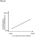
Fig. 10 is a graph in a relationship between the T/C revolution speed and a compression ratio difference. In the graph inFig. 10 , the lateral axis indicates the T/C revolution speed, and the vertical axis indicates the compression ratio difference. Here, the compression ratio difference is a difference between the set compression ratio and the target compression ratio. The higher the T/C revolution speed becomes, the wider the compression ratio difference tends to be. That is, even if the T/C revolution speed increases, in this embodiment, the target compression ratio is not set as high as the set compression ratio. This is because it is configured such that, by lowering the target compression ratio, even if the acceleration request is made again, the mechanical compression ratio can be returned to the low compression ratio early. -
Fig. 11 is an explanatory view of a relationship between the compression ratio changing speed and the supercharging pressure changing speed. InFig. 11 , the lateral axis indicates the compression ratio changing speed, and the vertical axis indicates the supercharging pressure changing speed. Here, the compression ratio changing speed is a speed at which the variable compression-ratio mechanism 101 can change the mechanical compression ratio. The supercharging pressure changing speed is a changing speed of the supercharging pressure in the turbo supercharger 7. - Moreover,
Fig. 11 illustrates a compression ratio changing speed limit. Since the variable compression-ratio mechanism 101 changes the mechanical compression ratio by the compression-ratio changing actuator 131, the compression ratio changing speed is limited by an operating speed of the compression-ratio changing actuator. Thus, the compression ratio changing speed cannot be made higher than the compression ratio changing speed limit. It is needless to say that the supercharging pressure changing speed also has a limit, but since the compression ratio changing speed is slower than the supercharging pressure changing speed, its limit comes earlier. - Moreover,
Fig. 11 illustrates a plurality of threshold values of knocking characteristics. The knocking characteristics are different depending on theengine 100. The engine with excellent knocking characteristics has a line of the threshold value closer to "good" in the figure, while the engine with poor knocking characteristics has a line of the threshold value closer to "poor" in the figure. - Then, according to the line indicating the threshold value of the knocking characteristics, when the compression ratio changing speed is high, the changing speed of the supercharging pressure can be also made high. The changing speed of the supercharging pressure has a substantially proportional relationship with the T/C revolution of the turbo supercharger 7. Thus, if the compression ratio changing speed is high, the T/C revolution speed threshold value of the T/C revolution can be also set high in general.
- From the above, it is known that the target compression ratio can be acquired from the engine revolution speed and the T/C revolution speed, but if the operation speed of the compression-
ratio changing actuator 131 is high, and the compression ratio changing speed is high, the T/C revolution speed threshold value can be also set high for that portion. - In executing the aforementioned control, it may be so configured that the
waste gate valve 19 is closed even after the T/C revolution speed falls below the T/C revolution speed threshold value Tt. By configuring as above, the supercharging pressure is held, and the revolution speed of the turbo supercharger 7 can be raised rapidly at the re-acceleration request. And even if the T/C revolution speed can be raised rapidly, since the mechanical compression ratio is maintained low as described above, occurrence of knocking can be suppressed. - Subsequently, effects of this embodiment will be described.
- According to the aforementioned embodiment, the
engine 100 includes the variable compression-ratio mechanism 101 for changing the mechanical compression ratio of theengine 100 and the turbo supercharger 7 for supplying a compressed air to theengine 100. And thecontroller 50 controls the variable compression-ratio mechanism 101 by setting the target compression ratio such that the higher the responsiveness of the supercharging pressure rise by the turbo supercharger 7 is, the lower the target compression ratio becomes. - By configuring as above, the higher the responsiveness of the supercharging pressure rise by the turbo supercharger 7 is, to the lower target compression ratio the mechanical compression ratio can be set. And the mechanical compression ratio can be rapidly returned to the low compression ratio at which knocking cannot occur easily even if the supercharging pressure rises by the re-acceleration request. That is, since occurrence of knocking at the re-acceleration request can be suppressed, retard of the ignition timing can be also suppressed. And torque response and the in-use fuel economy can be improved.
- Moreover, the target compression ratio is a mechanical compression ratio which can lower the mechanical compression ratio to a degree capable of suppressing knocking even if the variable compression-
ratio mechanism 101 is operated after the re-acceleration request. By configuring as above, the target compression ratio which can suppress occurrence of knocking at the re-acceleration request can be appropriately determined. - Moreover, the
controller 50 determines that the higher the exhaust energy of theengine 100 is, the higher the responsiveness of the supercharging pressure rise is. The exhaust energy of theengine 100 and the responsiveness of the supercharging pressure rise by the turbo supercharger 7 have a correlation. Thus, by configuring as above, the target compression ratio at which knocking cannot occur easily can be appropriately determined on the basis of the exhaust energy of theengine 100. - Moreover, the
controller 50 determines that the higher the revolution speed of the turbo supercharger 7 is, the higher the responsiveness of the supercharging pressure rise is. The revolution speed of the turbo supercharger 7 and the responsiveness of the supercharging pressure rise by the turbo supercharger 7 have a correlation. Thus, by configuring as above, the target compression ratio at which knocking cannot occur easily can be appropriately determined on the basis of the revolution speed of the turbo supercharger 7. - Moreover, the
controller 50 controls the variable compression-ratio mechanism 101 so that, when the T/C revolution speed falls below the T/C revolution speed threshold value, the raising of the mechanical compression ratio is started. By configuring as above, fuel economy after deceleration can be improved by increasing the mechanical compression ratio. Moreover, timing of increasing the mechanical compression ratio is delayed until the T/C revolution speed falls below the T/C revolution speed threshold value. Thus, even if the acceleration/deceleration request changes from the deceleration request to the acceleration request, and the revolution speed of the turbo supercharger 7 rises, the mechanical compression ratio can be lowered to the mechanical compression ratio at which knocking cannot occur easily. At this time, since the T/C revolution speed threshold value is determined by considering the lowering speed of the mechanical compression ratio and the rising speed of the revolution speed of the turbo supercharger 7, occurrence of knocking can be suppressed more reliably. - Moreover, the higher the revolution speed of the
engine 100 is, the lower the T/C revolution speed threshold value is set. Ease of rising of the T/C revolution speed is different depending on the revolution speed of theengine 100. Thus, by changing the T/C revolution speed threshold value in accordance with the revolution speed of the variablecompression ratio engine 100, the T/C revolution speed threshold value regulating timing of maintaining the mechanical compression ratio at the low mechanical compression ratio can be determined appropriately. - Moreover, it is preferable that the
waste gate valve 19 for allowing the exhaust gas between the variablecompression ratio engine 100 and the turbo supercharger 7 to escape is provided, and thewaste gate valve 19 is closed even after the revolution speed of the turbo supercharger 7 falls below the predetermined speed. By configuring as above, the supercharging pressure is held, and the revolution speed of the turbo supercharger 7 can be raised rapidly at re-acceleration. And even if the revolution speed of the turbo supercharger 7 can be raised rapidly as described above, since the mechanical compression ratio is maintained low, occurrence of knocking can be suppressed. - Moreover, the engine system 1 includes the T/C revolution
speed detection sensor 32 for detecting the revolution speed of the turbo supercharger 7. By configuring as above, since the revolution speed of the turbo supercharger 7 can be directly measured, the variable compression-ratio mechanism 101 can be controlled on the basis of the accurate revolution speed of the turbo supercharger 7. - Moreover, the
controller 50 obtains a load situation of an operation of theengine 100, and if the operation of theengine 100 changes from a low load to a high load, thecontroller 50 changes the compression ratio from the high compression ratio to the low compression ratio. Moreover, if the operation of theengine 100 changes from the high load to the low load, after the intensity of the exhaust energy falls to a predetermined value or less, the compression ratio is returned from the low compression ratio to the high compression ratio. By configuring as above, occurrence of knocking can be suppressed at the re-acceleration request and thus, retard of the ignition timing can be also suppressed. And the torque response and the in-use fuel economy can be improved. - Moreover, when the T/C revolution speed is obtained, and if the T/C revolution speed falls to a predetermined value or less, it can be determined that the intensity of the exhaust energy becomes a predetermined value or less. At this time, the T/C revolution speed may be detected or may be estimated. Moreover, when the exhaust temperature on the upstream side of the turbo supercharger 7 is obtained, and if the exhaust temperature falls to a predetermined value or less, it can be determined that the intensity of the exhaust energy becomes a predetermined value or less. At this time, the exhaust temperature may be detected or may be estimated. Moreover, when the exhaust pressure on the upstream side of the turbo supercharger 7 is obtained, and if the exhaust pressure falls to a predetermined value or less, it can be determined that the intensity of the exhaust energy becomes a predetermined value or less. At this time, the exhaust pressure may be detected or may be estimated.
-
Fig. 12 is a configuration view of an engine system in a second embodiment. In the aforementioned first embodiment, the revolution speed of the turbo supercharger 7 is measured by using the T/C revolution speed sensor, but in the second embodiment, the exhaust temperature is measured, and the T/C revolution speed is estimated from this exhaust temperature. - Thus, in the engine system 1 illustrated in
Fig. 12 , instead of the T/C revolution speed sensor, anexhaust temperature sensor 35 is provided on theexhaust passage 52. Theexhaust temperature sensor 35 is connected to thecontroller 50. And thecontroller 50 can obtain the exhaust temperature. -
Fig. 13 is an explanatory view of the T/C revolution speed with respect to the exhaust temperature. In the graph inFig. 13 , the lateral axis indicates the exhaust temperature, and the vertical axis indicates the T/C revolution speed. As illustrated inFig. 13 , the higher the exhaust temperature rises, the higher the T/C revolution speed also becomes. - The
controller 50 stores a map of the T/C revolution speed with respect to the exhaust temperature as illustrated inFig. 13 . And it estimates the T/C revolution speed on the basis of the obtained exhaust temperature. Thecontroller 50 executes the control in the aforementioned first embodiment on the basis of the estimated T/C revolution speed. - By configuring as above, even if the T/C revolution speed cannot be directly measured, the T/C revolution speed can be obtained on the basis of the exhaust temperature, and the control can be executed.
-
Fig. 14 is a configuration view of an engine system in a third embodiment. In the third embodiment, an exhaust pressure is measured, and the T/C revolution speed is estimated from this exhaust pressure. Thus, in the engine system 1 illustrated inFig. 14 , instead of the T/C revolution speed sensor, apressure sensor 36 is provided on theexhaust passage 52. Thepressure sensor 36 is connected to thecontroller 50. As a result, thecontroller 50 can obtain an exhaust pressure. -
Fig. 15 is an explanatory view of the T/C revolution speed with respect to the exhaust pressure. In the graph inFig. 15 , the lateral axis indicates the exhaust pressure, and the vertical axis indicates the T/C revolution speed. As illustrated inFig. 15 , as the exhaust pressure becomes high, the T/C revolution speed tends to be high. - The
controller 50 stores a map of the T/C revolution speed with respect to the exhaust pressure as illustrated inFig. 15 . Then, it estimates the T/C revolution speed on the basis of the obtained exhaust pressure. Thecontroller 50 can execute control by obtaining the estimated T/C revolution speed. - By configuring as above, even if the T/C revolution speed cannot be directly measured, the T/C revolution speed can be obtained on the basis of the exhaust pressure, and the control can be executed.
- The embodiments of the present invention have been described, but the aforementioned embodiments only illustrate a part of application examples of the present invention and are not intended to limit the technical scope of the present invention to specific configuration of the aforementioned embodiments. For example, the turbo supercharger 7 may be a supercharger.
- Each of the aforementioned embodiments has been described as the respective independent embodiments, but they may be combined as appropriate.
Claims (13)
- A control device of an engine, comprising:a variable compression-ratio mechanism adapted to change a compression ratio of an engine; anda supercharger adapted to supply a compressed air to the engine, whereinthe variable compression-ratio mechanism is controlled by setting target compression ratio such that the higher responsiveness of a supercharging pressure rise by the supercharger is, the lower the target compression ratio is.
- The control device of an engine according to claim 1, wherein
the target compression ratio is a compression ratio which can be lowered to a compression ratio capable of suppressing knocking even if the variable compression-ratio mechanism is operated after a re-acceleration request is made. - The control device of an engine according to claim 1 or 2, wherein
the supercharger is a supercharger driven by an exhaust of the engine; and
the higher exhaust energy of the engine is, the higher the responsiveness is determined to be. - The control device of an engine according to any one of claims 1 to 3, wherein
the supercharger is a supercharger driven by an exhaust of the engine; and
the higher a revolution speed of the supercharger is, the higher the responsiveness is determined to be. - The control device of an engine according to claim 4, wherein
the variable compression-ratio mechanism is controlled such that, when a revolution speed of the supercharger lowers below a predetermined speed, raising of the compression ratio to the target compression ratio is started. - The control device of an engine according to claim 5, wherein
the higher a revolution speed of the engine is, the lower the predetermined speed is. - The control device of an engine according to claim 5 or 6, wherein
a waste gate valve adapted to allow an exhaust gas between the engine and the supercharger to escape is provided; and
the waste gate valve is closed even after a revolution speed of the supercharger lowers below the predetermined speed. - The control device of an engine according to any one of claims 4 to 7, wherein
a revolution speed detection sensor adapted to detect a revolution speed of the supercharger is provided. - The control device of an engine according to any one of claims 4 to 7, wherein
on the basis of an exhaust temperature in an exhaust passage on an upstream side of the supercharger or a pressure in the exhaust passage on the upstream side of the supercharger, a revolution speed of the supercharger is estimated. - A control method of an engine including:a variable compression-ratio mechanism adapted to change a compression ratio of an engine; anda supercharger adapted to supercharge an intake air by using exhaust energy of the engine, whereina load situation of an operation of the engine is acquired;when the operation of the engine changes from a low load to a high load, a compression ratio is changed from a high compression ratio to a low compression ratio; andwhen the operation of the engine changes from the high load to the low load, the compression ratio is returned from a low compression ratio to a high compression ratio after intensity of the exhaust energy falls to a predetermined value or less.
- The control method of an engine according to claim 10, wherein
a revolution speed of the supercharger is obtained; and
when the revolution speed of the supercharger falls to a predetermined value or less, intensity of the exhaust energy is determined to have fallen to a predetermined value or less. - The control method of an engine according to claim 10, wherein
an exhaust temperature on an upstream side of the supercharger is obtained; and
when the exhaust temperature on the upstream side of the supercharger falls to a predetermined value or less, intensity of the exhaust energy is determined to have fallen to a predetermined value or less. - The control method of an engine according to claim 10, wherein
an exhaust pressure on an upstream side of the supercharger is obtained; and
when the exhaust pressure on the upstream side of the supercharger falls to a predetermined value or less, intensity of the exhaust energy is determined to have fallen to a predetermined value or less.
Applications Claiming Priority (1)
| Application Number | Priority Date | Filing Date | Title |
|---|---|---|---|
| PCT/JP2015/073399 WO2017029763A1 (en) | 2015-08-20 | 2015-08-20 | Engine control device and engine control method |
Publications (3)
| Publication Number | Publication Date |
|---|---|
| EP3339611A1 true EP3339611A1 (en) | 2018-06-27 |
| EP3339611A4 EP3339611A4 (en) | 2018-08-15 |
| EP3339611B1 EP3339611B1 (en) | 2020-11-25 |
Family
ID=58051298
Family Applications (1)
| Application Number | Title | Priority Date | Filing Date |
|---|---|---|---|
| EP15901745.8A Active EP3339611B1 (en) | 2015-08-20 | 2015-08-20 | Engine control device and engine control method |
Country Status (10)
| Country | Link |
|---|---|
| US (1) | US10344684B2 (en) |
| EP (1) | EP3339611B1 (en) |
| JP (1) | JP6439875B2 (en) |
| KR (1) | KR101851923B1 (en) |
| CN (1) | CN107923321B (en) |
| BR (1) | BR112018003259B1 (en) |
| CA (1) | CA2996105C (en) |
| MX (1) | MX2018001830A (en) |
| RU (1) | RU2677298C1 (en) |
| WO (1) | WO2017029763A1 (en) |
Families Citing this family (1)
| Publication number | Priority date | Publication date | Assignee | Title |
|---|---|---|---|---|
| DE102017207419A1 (en) * | 2017-05-03 | 2018-11-08 | Robert Bosch Gmbh | Method and device for operating an internal combustion engine with adjustable compression ratio |
Family Cites Families (36)
| Publication number | Priority date | Publication date | Assignee | Title |
|---|---|---|---|---|
| GB712613A (en) * | 1950-11-28 | 1954-07-28 | Miller Ralph | Improvements in or relating to internal combustion engines |
| US4233815A (en) * | 1970-05-05 | 1980-11-18 | Etat Francais | Methods of supercharging a diesel engine, in supercharged diesel engines, and in supercharging units for diesel engines |
| JPS57151034A (en) * | 1981-03-13 | 1982-09-18 | Nissan Motor Co Ltd | Control device of air-fuel ratio for internal combustion engine with supercharger |
| JPS5848716A (en) * | 1981-09-03 | 1983-03-22 | Toyota Motor Corp | Controller of turbo charger for engine |
| JPS59160053A (en) * | 1983-03-02 | 1984-09-10 | Mazda Motor Corp | Safety device for engine with turbocharger |
| US4996966A (en) * | 1988-01-19 | 1991-03-05 | Mazda Motor Corporation | Supercharged engine |
| US5848716A (en) * | 1997-10-02 | 1998-12-15 | Waranius; Kenneth E. | Portable stick locker with removable hangers |
| JP2001227367A (en) | 2000-02-16 | 2001-08-24 | Nissan Motor Co Ltd | Reciprocating internal combustion engine |
| JP3968957B2 (en) * | 2000-06-02 | 2007-08-29 | 日産自動車株式会社 | Internal combustion engine |
| JP4415464B2 (en) * | 2000-09-04 | 2010-02-17 | 日産自動車株式会社 | Turbocharged internal combustion engine with variable compression ratio device |
| JP4134830B2 (en) * | 2002-07-11 | 2008-08-20 | 日産自動車株式会社 | COMPRESSION RATIO CONTROL DEVICE FOR INTERNAL COMBUSTION ENGINE |
| JP4269909B2 (en) * | 2003-11-27 | 2009-05-27 | 日産自動車株式会社 | Control device and control method for variable compression ratio internal combustion engine |
| US7104120B2 (en) * | 2004-03-02 | 2006-09-12 | Caterpillar Inc. | Method and system of determining life of turbocharger |
| EP1808592A4 (en) * | 2004-11-02 | 2009-09-16 | Honda Motor Co Ltd | Plant and internal combustion engine control device |
| JP4395099B2 (en) * | 2005-05-20 | 2010-01-06 | トヨタ自動車株式会社 | Control device for an internal combustion engine with a supercharger |
| US20070028890A1 (en) * | 2005-08-08 | 2007-02-08 | Brown Cory A | Turbocharged internal combustion engine and method of operating same |
| CN101082318B (en) * | 2006-05-31 | 2011-09-21 | 卡特彼勒公司 | Turbo-charger control system |
| JP2008095651A (en) * | 2006-10-16 | 2008-04-24 | Nissan Motor Co Ltd | Control device for diesel engine |
| US7631552B2 (en) * | 2006-12-22 | 2009-12-15 | Detroit Diesel Corporation | Method of verifying component functionality on EGR and air systems |
| JP2009005651A (en) * | 2007-06-29 | 2009-01-15 | Institute Of Physical & Chemical Research | Method for preserving spermatid |
| JP5332645B2 (en) * | 2008-03-03 | 2013-11-06 | 日産自動車株式会社 | In-cylinder direct injection internal combustion engine |
| US8106699B2 (en) * | 2008-07-29 | 2012-01-31 | Qualcomm Incorporated | High signal level compliant input/output circuits |
| JP5045850B2 (en) * | 2009-04-28 | 2012-10-10 | トヨタ自動車株式会社 | Spark ignition internal combustion engine |
| CN102137993B (en) * | 2009-05-01 | 2014-06-18 | 丰田自动车株式会社 | Spark-ignited internal combustion engine |
| JP5229143B2 (en) * | 2009-07-15 | 2013-07-03 | 日産自動車株式会社 | Engine control device |
| DE102010021449B4 (en) * | 2010-05-25 | 2012-09-13 | Continental Automotive Gmbh | Method for operating an internal combustion engine and internal combustion engine |
| JP5804756B2 (en) * | 2011-04-15 | 2015-11-04 | 三菱重工業株式会社 | Supercharger system, internal combustion engine, and supercharger system control method |
| DE102011081844A1 (en) * | 2011-08-31 | 2013-02-28 | Ford Global Technologies, Llc | Method for operating a supercharged internal combustion engine and internal combustion engine for carrying out such a method |
| CN103857893B (en) * | 2011-11-01 | 2016-08-17 | 日产自动车株式会社 | The control device of internal combustion engine and control method |
| JP6010905B2 (en) * | 2011-12-19 | 2016-10-19 | いすゞ自動車株式会社 | Control method and control apparatus for internal combustion engine |
| JP5978662B2 (en) * | 2012-03-09 | 2016-08-24 | マツダ株式会社 | Control device for diesel engine with turbocharger |
| JP2014062498A (en) * | 2012-09-21 | 2014-04-10 | Hitachi Automotive Systems Ltd | Control device of internal combustion engine |
| US9695762B2 (en) * | 2012-10-09 | 2017-07-04 | Toyota Jidosha Kabushiki Kaisha | Internal combustion engine provided with variable compression ratio mechanism |
| JP6013223B2 (en) * | 2013-02-19 | 2016-10-25 | トヨタ自動車株式会社 | Hydraulic control device for engine |
| JP5989569B2 (en) * | 2013-02-19 | 2016-09-07 | トヨタ自動車株式会社 | Hydraulic control device for engine |
| DE102015203973A1 (en) * | 2014-03-24 | 2015-09-24 | Ford Global Technologies, Llc | Method for carrying out a charge exchange in an internal combustion engine |
-
2015
- 2015-08-20 US US15/753,099 patent/US10344684B2/en active Active
- 2015-08-20 BR BR112018003259-0A patent/BR112018003259B1/en active IP Right Grant
- 2015-08-20 CN CN201580082440.9A patent/CN107923321B/en active Active
- 2015-08-20 JP JP2017535221A patent/JP6439875B2/en active Active
- 2015-08-20 WO PCT/JP2015/073399 patent/WO2017029763A1/en active Application Filing
- 2015-08-20 CA CA2996105A patent/CA2996105C/en active Active
- 2015-08-20 KR KR1020187005057A patent/KR101851923B1/en active IP Right Grant
- 2015-08-20 RU RU2018105068A patent/RU2677298C1/en active
- 2015-08-20 EP EP15901745.8A patent/EP3339611B1/en active Active
- 2015-08-20 MX MX2018001830A patent/MX2018001830A/en active IP Right Grant
Also Published As
| Publication number | Publication date |
|---|---|
| RU2677298C1 (en) | 2019-01-16 |
| BR112018003259A2 (en) | 2018-09-25 |
| JPWO2017029763A1 (en) | 2018-06-07 |
| KR20180029074A (en) | 2018-03-19 |
| US20190010862A1 (en) | 2019-01-10 |
| BR112018003259B1 (en) | 2022-10-04 |
| CA2996105A1 (en) | 2017-02-23 |
| CN107923321A (en) | 2018-04-17 |
| EP3339611A4 (en) | 2018-08-15 |
| EP3339611B1 (en) | 2020-11-25 |
| CN107923321B (en) | 2019-03-22 |
| JP6439875B2 (en) | 2018-12-19 |
| MX2018001830A (en) | 2018-05-16 |
| CA2996105C (en) | 2018-06-19 |
| US10344684B2 (en) | 2019-07-09 |
| KR101851923B1 (en) | 2018-06-07 |
| WO2017029763A1 (en) | 2017-02-23 |
Similar Documents
| Publication | Publication Date | Title |
|---|---|---|
| US10087822B2 (en) | Control apparatus for internal combustion engine | |
| US9494098B2 (en) | Method for detecting combustion noise in internal combustion engine, combustion noise detection device, and device for controlling internal combustion engine | |
| JP5680169B1 (en) | Control device and control method for internal combustion engine | |
| JP5708820B2 (en) | Control device and control method for internal combustion engine | |
| EP2963263A1 (en) | Control device for internal combustion engine | |
| US20150219024A1 (en) | Internal combustion engine control device and method | |
| CN107002573B (en) | Controller for internal combustion engine | |
| CN107035511A (en) | The control device of internal combustion engine | |
| US11187166B2 (en) | Internal combustion engine and method of controlling same | |
| US10190519B2 (en) | Control device for internal combustion engine | |
| US10344684B2 (en) | Control device of engine and control method of engine | |
| CN109555616B (en) | Control apparatus for engine | |
| CN110730861B (en) | Method and device for controlling internal combustion engine | |
| US20150136092A1 (en) | Control device for internal combustion engine | |
| US10876483B2 (en) | Control device for internal combustion engine | |
| JP6406300B2 (en) | Engine control device |
Legal Events
| Date | Code | Title | Description |
|---|---|---|---|
| STAA | Information on the status of an ep patent application or granted ep patent |
Free format text: STATUS: THE INTERNATIONAL PUBLICATION HAS BEEN MADE |
|
| PUAI | Public reference made under article 153(3) epc to a published international application that has entered the european phase |
Free format text: ORIGINAL CODE: 0009012 |
|
| STAA | Information on the status of an ep patent application or granted ep patent |
Free format text: STATUS: REQUEST FOR EXAMINATION WAS MADE |
|
| 17P | Request for examination filed |
Effective date: 20180227 |
|
| AK | Designated contracting states |
Kind code of ref document: A1 Designated state(s): AL AT BE BG CH CY CZ DE DK EE ES FI FR GB GR HR HU IE IS IT LI LT LU LV MC MK MT NL NO PL PT RO RS SE SI SK SM TR |
|
| AX | Request for extension of the european patent |
Extension state: BA ME |
|
| RIC1 | Information provided on ipc code assigned before grant |
Ipc: F02B 75/04 20060101ALI20180705BHEP Ipc: F02D 15/00 20060101ALI20180705BHEP Ipc: F02D 41/12 20060101ALI20180705BHEP Ipc: F02D 41/14 20060101ALN20180705BHEP Ipc: F02D 41/00 20060101ALI20180705BHEP Ipc: F02D 15/02 20060101AFI20180705BHEP |
|
| A4 | Supplementary search report drawn up and despatched |
Effective date: 20180712 |
|
| DAV | Request for validation of the european patent (deleted) | ||
| DAX | Request for extension of the european patent (deleted) | ||
| STAA | Information on the status of an ep patent application or granted ep patent |
Free format text: STATUS: EXAMINATION IS IN PROGRESS |
|
| 17Q | First examination report despatched |
Effective date: 20190308 |
|
| GRAP | Despatch of communication of intention to grant a patent |
Free format text: ORIGINAL CODE: EPIDOSNIGR1 |
|
| STAA | Information on the status of an ep patent application or granted ep patent |
Free format text: STATUS: GRANT OF PATENT IS INTENDED |
|
| RIC1 | Information provided on ipc code assigned before grant |
Ipc: F02D 15/02 20060101AFI20200807BHEP Ipc: F02D 41/14 20060101ALN20200807BHEP Ipc: F02B 75/04 20060101ALI20200807BHEP Ipc: F02D 41/00 20060101ALI20200807BHEP Ipc: F02D 41/12 20060101ALI20200807BHEP Ipc: F02D 15/00 20060101ALI20200807BHEP |
|
| INTG | Intention to grant announced |
Effective date: 20200909 |
|
| GRAS | Grant fee paid |
Free format text: ORIGINAL CODE: EPIDOSNIGR3 |
|
| GRAA | (expected) grant |
Free format text: ORIGINAL CODE: 0009210 |
|
| STAA | Information on the status of an ep patent application or granted ep patent |
Free format text: STATUS: THE PATENT HAS BEEN GRANTED |
|
| AK | Designated contracting states |
Kind code of ref document: B1 Designated state(s): AL AT BE BG CH CY CZ DE DK EE ES FI FR GB GR HR HU IE IS IT LI LT LU LV MC MK MT NL NO PL PT RO RS SE SI SK SM TR |
|
| RAP1 | Party data changed (applicant data changed or rights of an application transferred) |
Owner name: NISSAN MOTOR CO., LTD. |
|
| REG | Reference to a national code |
Ref country code: GB Ref legal event code: FG4D |
|
| REG | Reference to a national code |
Ref country code: CH Ref legal event code: EP |
|
| REG | Reference to a national code |
Ref country code: AT Ref legal event code: REF Ref document number: 1338581 Country of ref document: AT Kind code of ref document: T Effective date: 20201215 |
|
| REG | Reference to a national code |
Ref country code: DE Ref legal event code: R096 Ref document number: 602015062762 Country of ref document: DE |
|
| REG | Reference to a national code |
Ref country code: DE Ref legal event code: R082 Ref document number: 602015062762 Country of ref document: DE Representative=s name: HOEFER & PARTNER PATENTANWAELTE MBB, DE |
|
| REG | Reference to a national code |
Ref country code: IE Ref legal event code: FG4D |
|
| REG | Reference to a national code |
Ref country code: AT Ref legal event code: MK05 Ref document number: 1338581 Country of ref document: AT Kind code of ref document: T Effective date: 20201125 |
|
| REG | Reference to a national code |
Ref country code: NL Ref legal event code: MP Effective date: 20201125 |
|
| PG25 | Lapsed in a contracting state [announced via postgrant information from national office to epo] |
Ref country code: PT Free format text: LAPSE BECAUSE OF FAILURE TO SUBMIT A TRANSLATION OF THE DESCRIPTION OR TO PAY THE FEE WITHIN THE PRESCRIBED TIME-LIMIT Effective date: 20210325 Ref country code: RS Free format text: LAPSE BECAUSE OF FAILURE TO SUBMIT A TRANSLATION OF THE DESCRIPTION OR TO PAY THE FEE WITHIN THE PRESCRIBED TIME-LIMIT Effective date: 20201125 Ref country code: FI Free format text: LAPSE BECAUSE OF FAILURE TO SUBMIT A TRANSLATION OF THE DESCRIPTION OR TO PAY THE FEE WITHIN THE PRESCRIBED TIME-LIMIT Effective date: 20201125 Ref country code: NO Free format text: LAPSE BECAUSE OF FAILURE TO SUBMIT A TRANSLATION OF THE DESCRIPTION OR TO PAY THE FEE WITHIN THE PRESCRIBED TIME-LIMIT Effective date: 20210225 Ref country code: GR Free format text: LAPSE BECAUSE OF FAILURE TO SUBMIT A TRANSLATION OF THE DESCRIPTION OR TO PAY THE FEE WITHIN THE PRESCRIBED TIME-LIMIT Effective date: 20210226 |
|
| PG25 | Lapsed in a contracting state [announced via postgrant information from national office to epo] |
Ref country code: LV Free format text: LAPSE BECAUSE OF FAILURE TO SUBMIT A TRANSLATION OF THE DESCRIPTION OR TO PAY THE FEE WITHIN THE PRESCRIBED TIME-LIMIT Effective date: 20201125 Ref country code: SE Free format text: LAPSE BECAUSE OF FAILURE TO SUBMIT A TRANSLATION OF THE DESCRIPTION OR TO PAY THE FEE WITHIN THE PRESCRIBED TIME-LIMIT Effective date: 20201125 Ref country code: PL Free format text: LAPSE BECAUSE OF FAILURE TO SUBMIT A TRANSLATION OF THE DESCRIPTION OR TO PAY THE FEE WITHIN THE PRESCRIBED TIME-LIMIT Effective date: 20201125 Ref country code: IS Free format text: LAPSE BECAUSE OF FAILURE TO SUBMIT A TRANSLATION OF THE DESCRIPTION OR TO PAY THE FEE WITHIN THE PRESCRIBED TIME-LIMIT Effective date: 20210325 Ref country code: BG Free format text: LAPSE BECAUSE OF FAILURE TO SUBMIT A TRANSLATION OF THE DESCRIPTION OR TO PAY THE FEE WITHIN THE PRESCRIBED TIME-LIMIT Effective date: 20210225 Ref country code: AT Free format text: LAPSE BECAUSE OF FAILURE TO SUBMIT A TRANSLATION OF THE DESCRIPTION OR TO PAY THE FEE WITHIN THE PRESCRIBED TIME-LIMIT Effective date: 20201125 |
|
| REG | Reference to a national code |
Ref country code: LT Ref legal event code: MG9D |
|
| PG25 | Lapsed in a contracting state [announced via postgrant information from national office to epo] |
Ref country code: HR Free format text: LAPSE BECAUSE OF FAILURE TO SUBMIT A TRANSLATION OF THE DESCRIPTION OR TO PAY THE FEE WITHIN THE PRESCRIBED TIME-LIMIT Effective date: 20201125 |
|
| PG25 | Lapsed in a contracting state [announced via postgrant information from national office to epo] |
Ref country code: LT Free format text: LAPSE BECAUSE OF FAILURE TO SUBMIT A TRANSLATION OF THE DESCRIPTION OR TO PAY THE FEE WITHIN THE PRESCRIBED TIME-LIMIT Effective date: 20201125 Ref country code: SM Free format text: LAPSE BECAUSE OF FAILURE TO SUBMIT A TRANSLATION OF THE DESCRIPTION OR TO PAY THE FEE WITHIN THE PRESCRIBED TIME-LIMIT Effective date: 20201125 Ref country code: EE Free format text: LAPSE BECAUSE OF FAILURE TO SUBMIT A TRANSLATION OF THE DESCRIPTION OR TO PAY THE FEE WITHIN THE PRESCRIBED TIME-LIMIT Effective date: 20201125 Ref country code: CZ Free format text: LAPSE BECAUSE OF FAILURE TO SUBMIT A TRANSLATION OF THE DESCRIPTION OR TO PAY THE FEE WITHIN THE PRESCRIBED TIME-LIMIT Effective date: 20201125 Ref country code: RO Free format text: LAPSE BECAUSE OF FAILURE TO SUBMIT A TRANSLATION OF THE DESCRIPTION OR TO PAY THE FEE WITHIN THE PRESCRIBED TIME-LIMIT Effective date: 20201125 Ref country code: SK Free format text: LAPSE BECAUSE OF FAILURE TO SUBMIT A TRANSLATION OF THE DESCRIPTION OR TO PAY THE FEE WITHIN THE PRESCRIBED TIME-LIMIT Effective date: 20201125 |
|
| REG | Reference to a national code |
Ref country code: DE Ref legal event code: R097 Ref document number: 602015062762 Country of ref document: DE |
|
| PG25 | Lapsed in a contracting state [announced via postgrant information from national office to epo] |
Ref country code: DK Free format text: LAPSE BECAUSE OF FAILURE TO SUBMIT A TRANSLATION OF THE DESCRIPTION OR TO PAY THE FEE WITHIN THE PRESCRIBED TIME-LIMIT Effective date: 20201125 |
|
| PLBE | No opposition filed within time limit |
Free format text: ORIGINAL CODE: 0009261 |
|
| STAA | Information on the status of an ep patent application or granted ep patent |
Free format text: STATUS: NO OPPOSITION FILED WITHIN TIME LIMIT |
|
| PG25 | Lapsed in a contracting state [announced via postgrant information from national office to epo] |
Ref country code: NL Free format text: LAPSE BECAUSE OF FAILURE TO SUBMIT A TRANSLATION OF THE DESCRIPTION OR TO PAY THE FEE WITHIN THE PRESCRIBED TIME-LIMIT Effective date: 20201125 Ref country code: AL Free format text: LAPSE BECAUSE OF FAILURE TO SUBMIT A TRANSLATION OF THE DESCRIPTION OR TO PAY THE FEE WITHIN THE PRESCRIBED TIME-LIMIT Effective date: 20201125 Ref country code: IT Free format text: LAPSE BECAUSE OF FAILURE TO SUBMIT A TRANSLATION OF THE DESCRIPTION OR TO PAY THE FEE WITHIN THE PRESCRIBED TIME-LIMIT Effective date: 20201125 |
|
| 26N | No opposition filed |
Effective date: 20210826 |
|
| PG25 | Lapsed in a contracting state [announced via postgrant information from national office to epo] |
Ref country code: SI Free format text: LAPSE BECAUSE OF FAILURE TO SUBMIT A TRANSLATION OF THE DESCRIPTION OR TO PAY THE FEE WITHIN THE PRESCRIBED TIME-LIMIT Effective date: 20201125 |
|
| PG25 | Lapsed in a contracting state [announced via postgrant information from national office to epo] |
Ref country code: ES Free format text: LAPSE BECAUSE OF FAILURE TO SUBMIT A TRANSLATION OF THE DESCRIPTION OR TO PAY THE FEE WITHIN THE PRESCRIBED TIME-LIMIT Effective date: 20201125 |
|
| REG | Reference to a national code |
Ref country code: CH Ref legal event code: PL |
|
| PG25 | Lapsed in a contracting state [announced via postgrant information from national office to epo] |
Ref country code: MC Free format text: LAPSE BECAUSE OF FAILURE TO SUBMIT A TRANSLATION OF THE DESCRIPTION OR TO PAY THE FEE WITHIN THE PRESCRIBED TIME-LIMIT Effective date: 20201125 |
|
| REG | Reference to a national code |
Ref country code: BE Ref legal event code: MM Effective date: 20210831 |
|
| PG25 | Lapsed in a contracting state [announced via postgrant information from national office to epo] |
Ref country code: LI Free format text: LAPSE BECAUSE OF NON-PAYMENT OF DUE FEES Effective date: 20210831 Ref country code: CH Free format text: LAPSE BECAUSE OF NON-PAYMENT OF DUE FEES Effective date: 20210831 |
|
| PG25 | Lapsed in a contracting state [announced via postgrant information from national office to epo] |
Ref country code: IS Free format text: LAPSE BECAUSE OF FAILURE TO SUBMIT A TRANSLATION OF THE DESCRIPTION OR TO PAY THE FEE WITHIN THE PRESCRIBED TIME-LIMIT Effective date: 20210325 Ref country code: LU Free format text: LAPSE BECAUSE OF NON-PAYMENT OF DUE FEES Effective date: 20210820 |
|
| PG25 | Lapsed in a contracting state [announced via postgrant information from national office to epo] |
Ref country code: IE Free format text: LAPSE BECAUSE OF NON-PAYMENT OF DUE FEES Effective date: 20210820 Ref country code: BE Free format text: LAPSE BECAUSE OF NON-PAYMENT OF DUE FEES Effective date: 20210831 |
|
| PG25 | Lapsed in a contracting state [announced via postgrant information from national office to epo] |
Ref country code: HU Free format text: LAPSE BECAUSE OF FAILURE TO SUBMIT A TRANSLATION OF THE DESCRIPTION OR TO PAY THE FEE WITHIN THE PRESCRIBED TIME-LIMIT; INVALID AB INITIO Effective date: 20150820 |
|
| PG25 | Lapsed in a contracting state [announced via postgrant information from national office to epo] |
Ref country code: CY Free format text: LAPSE BECAUSE OF FAILURE TO SUBMIT A TRANSLATION OF THE DESCRIPTION OR TO PAY THE FEE WITHIN THE PRESCRIBED TIME-LIMIT Effective date: 20201125 |
|
| PGFP | Annual fee paid to national office [announced via postgrant information from national office to epo] |
Ref country code: GB Payment date: 20230720 Year of fee payment: 9 |
|
| PGFP | Annual fee paid to national office [announced via postgrant information from national office to epo] |
Ref country code: FR Payment date: 20230720 Year of fee payment: 9 Ref country code: DE Payment date: 20230720 Year of fee payment: 9 |