EP3339139A1 - Steel sheet member combination structure, automobile structural member, center pillar, bumper, and door beam - Google Patents
Steel sheet member combination structure, automobile structural member, center pillar, bumper, and door beam Download PDFInfo
- Publication number
- EP3339139A1 EP3339139A1 EP16837180.5A EP16837180A EP3339139A1 EP 3339139 A1 EP3339139 A1 EP 3339139A1 EP 16837180 A EP16837180 A EP 16837180A EP 3339139 A1 EP3339139 A1 EP 3339139A1
- Authority
- EP
- European Patent Office
- Prior art keywords
- wall portion
- steel sheet
- center pillar
- sheet member
- bumper
- Prior art date
- Legal status (The legal status is an assumption and is not a legal conclusion. Google has not performed a legal analysis and makes no representation as to the accuracy of the status listed.)
- Granted
Links
Images




Classifications
-
- F—MECHANICAL ENGINEERING; LIGHTING; HEATING; WEAPONS; BLASTING
- F16—ENGINEERING ELEMENTS AND UNITS; GENERAL MEASURES FOR PRODUCING AND MAINTAINING EFFECTIVE FUNCTIONING OF MACHINES OR INSTALLATIONS; THERMAL INSULATION IN GENERAL
- F16B—DEVICES FOR FASTENING OR SECURING CONSTRUCTIONAL ELEMENTS OR MACHINE PARTS TOGETHER, e.g. NAILS, BOLTS, CIRCLIPS, CLAMPS, CLIPS OR WEDGES; JOINTS OR JOINTING
- F16B5/00—Joining sheets or plates, e.g. panels, to one another or to strips or bars parallel to them
-
- B—PERFORMING OPERATIONS; TRANSPORTING
- B60—VEHICLES IN GENERAL
- B60J—WINDOWS, WINDSCREENS, NON-FIXED ROOFS, DOORS, OR SIMILAR DEVICES FOR VEHICLES; REMOVABLE EXTERNAL PROTECTIVE COVERINGS SPECIALLY ADAPTED FOR VEHICLES
- B60J5/00—Doors
- B60J5/04—Doors arranged at the vehicle sides
- B60J5/042—Reinforcement elements
- B60J5/0456—Behaviour during impact
-
- B—PERFORMING OPERATIONS; TRANSPORTING
- B62—LAND VEHICLES FOR TRAVELLING OTHERWISE THAN ON RAILS
- B62D—MOTOR VEHICLES; TRAILERS
- B62D25/00—Superstructure or monocoque structure sub-units; Parts or details thereof not otherwise provided for
- B62D25/04—Door pillars ; windshield pillars
-
- B—PERFORMING OPERATIONS; TRANSPORTING
- B60—VEHICLES IN GENERAL
- B60J—WINDOWS, WINDSCREENS, NON-FIXED ROOFS, DOORS, OR SIMILAR DEVICES FOR VEHICLES; REMOVABLE EXTERNAL PROTECTIVE COVERINGS SPECIALLY ADAPTED FOR VEHICLES
- B60J5/00—Doors
-
- B—PERFORMING OPERATIONS; TRANSPORTING
- B60—VEHICLES IN GENERAL
- B60J—WINDOWS, WINDSCREENS, NON-FIXED ROOFS, DOORS, OR SIMILAR DEVICES FOR VEHICLES; REMOVABLE EXTERNAL PROTECTIVE COVERINGS SPECIALLY ADAPTED FOR VEHICLES
- B60J5/00—Doors
- B60J5/04—Doors arranged at the vehicle sides
- B60J5/042—Reinforcement elements
- B60J5/0422—Elongated type elements, e.g. beams, cables, belts or wires
- B60J5/0438—Elongated type elements, e.g. beams, cables, belts or wires characterised by the type of elongated elements
- B60J5/0443—Beams
-
- B—PERFORMING OPERATIONS; TRANSPORTING
- B60—VEHICLES IN GENERAL
- B60J—WINDOWS, WINDSCREENS, NON-FIXED ROOFS, DOORS, OR SIMILAR DEVICES FOR VEHICLES; REMOVABLE EXTERNAL PROTECTIVE COVERINGS SPECIALLY ADAPTED FOR VEHICLES
- B60J5/00—Doors
- B60J5/04—Doors arranged at the vehicle sides
- B60J5/048—Doors arranged at the vehicle sides characterised by the material
-
- B—PERFORMING OPERATIONS; TRANSPORTING
- B60—VEHICLES IN GENERAL
- B60R—VEHICLES, VEHICLE FITTINGS, OR VEHICLE PARTS, NOT OTHERWISE PROVIDED FOR
- B60R19/00—Wheel guards; Radiator guards, e.g. grilles; Obstruction removers; Fittings damping bouncing force in collisions
- B60R19/02—Bumpers, i.e. impact receiving or absorbing members for protecting vehicles or fending off blows from other vehicles or objects
- B60R19/18—Bumpers, i.e. impact receiving or absorbing members for protecting vehicles or fending off blows from other vehicles or objects characterised by the cross-section; Means within the bumper to absorb impact
-
- B—PERFORMING OPERATIONS; TRANSPORTING
- B62—LAND VEHICLES FOR TRAVELLING OTHERWISE THAN ON RAILS
- B62D—MOTOR VEHICLES; TRAILERS
- B62D25/00—Superstructure or monocoque structure sub-units; Parts or details thereof not otherwise provided for
-
- B—PERFORMING OPERATIONS; TRANSPORTING
- B60—VEHICLES IN GENERAL
- B60R—VEHICLES, VEHICLE FITTINGS, OR VEHICLE PARTS, NOT OTHERWISE PROVIDED FOR
- B60R19/00—Wheel guards; Radiator guards, e.g. grilles; Obstruction removers; Fittings damping bouncing force in collisions
- B60R19/02—Bumpers, i.e. impact receiving or absorbing members for protecting vehicles or fending off blows from other vehicles or objects
- B60R19/18—Bumpers, i.e. impact receiving or absorbing members for protecting vehicles or fending off blows from other vehicles or objects characterised by the cross-section; Means within the bumper to absorb impact
- B60R2019/1806—Structural beams therefor, e.g. shock-absorbing
- B60R2019/1813—Structural beams therefor, e.g. shock-absorbing made of metal
Definitions
- the present invention relates to a steel sheet member combination structure, an automotive structural member, a center pillar, a bumper, and a door beam.
- Structural members constituting automotive bodies play a role of limiting the effect, on the inside of cabins, of impact in cases in which an automobile collides with an oncoming vehicle or an obstacle, an automobile is hit from a side of a vehicle body, or the like.
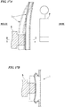
- FIG. 17A and FIG. 17B when an impactor 5 collides with a lower portion of a center pillar 1 which is one of structural members constituting an automotive body from a side of a vehicle body, and thus the center pillar receives a load, the lower portion of the center pillar 1 deforms so as to collapse toward the inside of the vehicle body in the width direction. Then, due to this deformation, the center pillar 1 absorbs collision energy from the impactor 5 and suppresses an upper portion of the center pillar 1 coming inside a cabin, thereby securing the safety of a passenger P.
- the center pillar 1 is broken before the load from the impactor 5 is sufficiently sustained, the collision energy from the impactor 5 cannot be sufficiently absorbed, and consequently, the upper portion of the center pillar 1 comes inside the cabin as shown in FIG. 17A .
- an increase in the sheet thickness of the center pillar 1 can be considered, but an increase in the sheet thickness leads to an increase in the vehicle weight. Therefore, it becomes important to improve the energy absorption efficiency (energy absorption amount per unit weight) when there is collision.
- Patent Document 1 discloses a technique in which a foamed material is provided in a center pillar, thereby increasing the initial reactive force to collision from a side of a vehicle body, suppressing the deformation of the center pillar coming inside a cabin due to collision, and improving the safety of passengers in the cabin.
- Patent Document 2 and Patent Document 3 disclose techniques in which a vulnerable portion such as a hole or a recess bead is formed in a lower portion of a center pillar, thereby inducing deformation due to collision mainly in a lower side portion of a vehicle body, suppressing the deformation coming inside a cabin, and improving the safety of passengers in the cabin.
- Patent Document 1 raw materials and manufacturing steps become complex, and thus manufacturing costs increase, and the energy absorption amount by the foamed material cannot be said to be sufficient. As a result, in order to improve the energy absorption efficiency in Patent Document 1, a large amount of a foamed material becomes necessary, and the manufacturing costs significantly increase.
- Patent Document 2 and Patent Document 3 there is a possibility that the vulnerable portion such as a hole may break during collision, and there is a possibility that deformation may concentrate in the vulnerable portion and thus cause local deformation. Therefore, in Patent Document 2 and Patent Document 3, the amount of absorbable energy becomes small, and consequently, it is difficult to improve the energy absorption efficiency.
- the present invention has been made in consideration of the above-described circumstances, and an object of the present invention is to provide a steel sheet member combination structure, an automotive structural member, a center pillar, a bumper, and a door beam which are capable of improving the collision energy absorption efficiency at low costs.
- the present invention employs the followings.
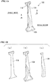
- FIG. 1A is a schematic perspective view showing a center pillar 100 (automotive structural member) according to a first embodiment of the present invention.
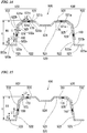
- FIG. 1B is an exploded perspective view of the center pillar 100, (a) is a view showing a center pillar inner 110, (b) is a view showing a state in which a center pillar outer 120 is joined to the center pillar inner 110, and (c) is a view showing a patch member 130 that is joined to the center pillar outer 120.
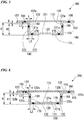
- FIG. 2 is a cross-sectional view in a direction of the A-A line in FIG. 1A .
- the center pillar 100 is long in one direction and includes the center pillar inner 110, the center pillar outer 120 (first steel sheet member) joined to the center pillar inner 110, and the patch member 130 (second steel sheet member) joined to the center pillar outer 120.
- the center pillar 100 is disposed on a side of an automotive body in the vertical direction.
- a cross-section of the center pillar 100 which is perpendicular to the longitudinal direction is a hollow cross-section, and, when an impact F is exerted from a side of a vehicle body, the center pillar receives a load from the impact F, bending-deforms, and absorbs collision energy.
- the center pillar inner 110 of the center pillar 100 has a flat sheet shape.
- the center pillar inner 110 is a steel sheet having, for example, a sheet thickness of 0.6 to 1.6 mm and a tensile strength of 980 MPa or higher.
- a steel sheet having a tensile strength of 1,180 MPa or higher is more preferably used as the center pillar inner 110.
- the center pillar outer 120 of the center pillar 100 is a steel sheet having a sheet thickness of 0.8 to 2.0 mm and a tensile strength of 980 MPa or higher.
- the center pillar outer 120 has a hat-like cross-section which is perpendicular to the longitudinal direction and includes a main wall portion 121 facing the center pillar inner 110, a pair of standing wall portions 122 that vertically stands from both ends 121a (both end edges) of the main wall portion 121, and a pair of flange portions 123 that is parallel to the main wall portion 121 and extends from one end 122a (end edge) of each of the standing wall portions 122 so as to separate from the main wall portion 121.
- a steel sheet having a tensile strength of 1,180 MPa or higher is more preferably used as the center pillar outer 120.
- the center pillar outer 120 is joined to an outer surface 110a (a surface toward the outside of the vehicle body) of the center pillar inner 110 by spot-welding the flange portions 123.
- spot-welding portions 150 are provided between the outer surface 110a of the center pillar inner 110 and inner surfaces 123a of the flange portions 123 of the center pillar outer 120.
- the center pillar inner 110 and the flange portions 123 of the center pillar outer 120 may be joined together by means of, for example, laser welding, brazing, or the like instead of spot welding.
- the patch member 130 of the center pillar 100 is a steel sheet having a sheet thickness of 0.8 to 3.0 mm and a tensile strength of 980 MPa or higher.
- the patch member 130 has a channel-like cross-sectional shape and includes a horizontal wall portion 131 and a pair of side wall portions 132 that vertically stands from both ends 131a (both end edges) of the horizontal wall portion 131.
- the patch member 130 is joined to an outer surface of the center pillar outer 120 by spot-welding the side wall portions 132 and the standing wall portions 122 of the center pillar outer 120 and spot-welding the horizontal wall portion 131 and the main wall portion 121 of the center pillar outer 120.
- spot-welding portions 160 first joint portions
- spot-welding portions 170 second joint portions
- the center pillar outer 120 and the patch member 130 may be joined together by means of, for example, laser welding, brazing, or the like instead of spot welding.
- the patch member 130 a variety of steel sheets such as a hot-stamped material can be used.
- a steel sheet having a tensile strength of 1,180 MPa or higher is more preferably used, and a steel sheet having a tensile strength of 1,500 MPa or higher is still more preferably used.
- the horizontal wall portion 131 of the patch member 130 has a shape that follows the shape of the main wall portion 121 of the center pillar outer 120.
- the side wall portion 132 of the patch member 130 has a shape that follows the shape of the standing wall portion 122 of the center pillar outer 120. That is, in the center pillar 100, the horizontal wall portion 131 of the patch member 130 abuts the main wall portion 121 of the center pillar outer 120, and the side wall portions 132 of the patch member 130 abut the standing wall portions 122 of the center pillar outer 120.
- the patch member 130 is joined to the center pillar outer 120, and thus it is possible to reinforce the center pillar outer 120.
- the patch member 130 is joined to the center pillar outer 120, and thus it is possible to reinforce only necessary portions. Therefore, compared with a case in which the sheet thickness of the entire center pillar outer 120 is increased, it is possible to reduce an increase in weight.
- the spot-welding portion 160 is preferably formed in a range of L1 (mm) from a side end surface 132b (tip end surface) of the side wall portion 132 of the patch member 130.
- L1 represents 40% of the height (the distance from the side end surface 132b of the side wall portion 132 to an outer surface 131c of the horizontal wall portion 131) of the side wall portion 132 of the patch member 130.
- At least a portion of the spot-welding portion 170 is preferably formed in a range of L2 (mm) from the inner surface 132a of the side wall portion 132.
- L2 represents 40% of the height (the distance from the side end surface 132b of the side wall portion 132 to the outer surface 131c of the horizontal wall portion 131) of the side wall portion 132 of the patch member 130.
- at least a portion of the spot-welding portion 170 is preferably formed in a range of L2 from an R stop.
- H (mm) represents larger one of the distance between an outer surface 123b of the flange portion 123 and the outer surface 121b of the main wall portion 121 and the distance between the outer surface 123b of the flange portion 123 and the outer surface 131c of the horizontal wall portion 131. That is, in the center pillar 100, since the patch member 130 is joined to the outer surface of the center pillar outer 120, the H represents the distance (height) from the outer surface 123b of the flange portion 123 of the center pillar outer 120 to the outer surface 131c of the horizontal wall portion 131 of the patch member 130.
- t (mm) represents the sum of the sheet thickness of the standing wall portion 122 of the center pillar outer 120 and the sheet thickness of the side wall portion 132 of the patch member 130.
- H1 (mm) represents a larger distance (height) of the distance between the side end surface 132b of the side wall portion 132 and the outer surface 121b of the main wall portion 121 and the distance between the side end surface 132b of the side wall portion 132 and the outer surface 131c of the horizontal wall portion 131. That is, in the center pillar 100, since the patch member 130 is joined to the outer surface of the center pillar outer 120, the H1 represents the distance (height) from the side end surface 132b of the side wall portion 132 to the outer surface 131c of the horizontal wall portion 131.
- the patch member 130 is joined to the center pillar outer 120, and thus the center pillar outer 120 is reinforced, and both Expression (1) and Expression (2) are satisfied. Therefore, it is possible to improve the energy absorption efficiency when the impact F is exerted.
- the reason for establishing Expression (1) and Expression (2) is as described below.
- H/t is preferably smaller.
- H/t is preferably 17.5 or less, more preferably 15.0 or less, and still more preferably 12.5 or less.
- the lower limit of H/t is not particularly limited, but H/t is, for example, 5.0 or more.
- H1/H is preferably 0.7 or more, and more preferably 0.8 or more.
- FIG. 3 An example of deformation occurring in a case in which the impact F is exerted on the center pillar 100 satisfying both Expressions (1) and (2) is shown in FIG. 3 .
- the center pillar 100 satisfies both Expressions (1) and (2), the standing wall portions 122 of the center pillar outer 120 are sufficiently reinforced by the patch member 130, and it is possible to prevent the standing wall portions 122 from easily buckling-deforming.
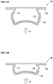
- FIG. 4A an example of deformation occurring in a case in which the impact F is exerted on a center pillar 50 not satisfying Expression (1) is shown in FIG. 4A .
- the center pillar 50 does not satisfy Expression (1), it is not possible to sufficiently reinforce the standing wall portions 122 of the center pillar outer 120 using the patch member 130, and the standing wall portions 122 easily buckling-deform.
- FIG. 4B an example of deformation occurring in a case in which the impact F is exerted on a center pillar 60 not satisfying Expression (2) is shown in FIG. 4B .
- the center pillar 60 does not satisfy Expression (2), it is not possible to sufficiently obtain the reinforcement effect of the patch member 130, and the standing wall portions 122 easily buckling-deform.
- the center pillar 100 of the present embodiment since the patch member 130 is joined to the center pillar outer 120, it is possible to reinforce only necessary portions without increasing the sheet thickness of the entire center pillar outer 120. Therefore, it is possible to reinforce the center pillar outer 120 while suppressing an increase in the weight of the center pillar 100.
- the center pillar outer 120 and the patch member 130 satisfy both Expression (1) and Expression (2), in a case in which an impact is exerted from a side of a vehicle body, it is possible to prevent the breakage of the standing wall portions 122 of the center pillar outer 120. Therefore, it is possible to improve the collision energy absorption efficiency at low costs.
- a predetermined distance D is preferably provided between the side end surface 132b of the side wall portion 132 of the patch member 130 and the outer surface 123b of the flange portion 123 of the center pillar outer 120 as shown in FIG. 2 (D>0).
- H1/H is preferably less than 1.0 ((H1/H) ⁇ 1.0).
- the distance D is more preferably set to, for example, 10% or more of H. That is, regarding Expression (2), H1/H is more preferably 0.9 or less.
- FIG. 6 is a horizontal cross-sectional view showing the center pillar 200 according to the present embodiment.
- the center pillar 100 according to the first embodiment a case in which the patch member 130 is joined to the outer surface of the center pillar outer 120 has been described.
- the patch member 130 is joined to an inner surface of the center pillar outer 120 as shown in FIG. 6 .
- the horizontal wall portion 131 of the patch member 130 is joined to an inner surface 121c of the main wall portion 121 of the center pillar outer 120 using the spot-welding portions 170, and the side wall portions 132 of the patch member 130 are joined to inner surfaces 122c of the standing wall portions 122 of the center pillar outer 120 using the spot-welding portions 160.
- the center pillar 200 according to the present embodiment is, similar to the center pillar 100 according to the first embodiment, capable of reinforcing the center pillar outer 120.
- the center pillar 200 is, similar to the center pillar 100 according to the first embodiment, capable of improving the collision energy absorption efficiency by satisfying Expression (1) and Expression (2).
- H (mm) becomes the distance (height) from the outer surface 123b of the flange portion 123 of the center pillar outer 120 to the outer surface 121b of the main wall portion 121 of the center pillar outer 120.
- H1 (mm) becomes the distance (height) from the side end surface 132b of the side wall portion 132 of the patch member 130 to the outer surface 121b of the main wall portion 121 of the center pillar outer 120.
- the channel-like patch member 130 is joined to the inner surface of the center pillar outer 120 .
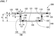
- the pair of patch members 140 having an L-like cross-sectional shape may be joined to the inner surface of the center pillar outer 120 as shown in FIG. 7 .
- the volume of the horizontal wall portions 131 of the patch members 140 which abut the main wall portion 121 of the center pillar outer 120 becomes small, and thus it is possible to reduce the weight of the center pillar 200.
- FIG. 8 is a schematic perspective view showing the bumper 300 (automotive structural member) according to a third embodiment of the present invention.
- FIG. 9 is a cross-sectional view in a direction of the B-B line in FIG. 8 .
- the bumper 300 includes a pair of patch members 330.
- the bumper 300 is long in one direction and includes a baseplate 310, a bumper main body 320 (first steel sheet member) joined to the baseplate 310, and the pair of patch members 330 (second steel sheet members) joined to the bumper main body 320.
- the bumper 300 is disposed on the front side or rear side of an automotive body.
- a cross-section of the bumper 300 which is perpendicular to the longitudinal direction is a hollow cross-section, and, when the impact F is exerted from the front side or rear side of a vehicle body, the bumper receives a load from the impact F, bending-deforms, and absorbs collision energy.
- the baseplate 310 of the bumper 300 has a flat sheet shape.
- the baseplate 310 of the bumper 300 is a steel sheet having, for example, a sheet thickness of 1.4 mm and a tensile strength of 980 MPa or higher.
- a steel sheet of 1,180 MPa or higher is more preferably used as the baseplate 310.
- the bumper main body 320 of the bumper 300 has a hat-like cross-section which is perpendicular to the longitudinal direction and is a steel sheet having a sheet thickness of 0.8 to 2.0 mm and a tensile strength of 980 MPa or higher.
- the bumper main body 320 includes a main wall portion 321 facing the baseplate 310, a pair of standing wall portions 322 that vertically stands from both ends 321a of the main wall portion 321, and a pair of flange portions 323 that is parallel to the main wall portion 321 and extends from one end 322a of each of the standing wall portions 322 so as to separate from the main wall portion 321.
- a steel sheet of 1,180 MPa or higher is more preferably used as the bumper main body 320.
- the main wall portion 321 of the bumper main body 320 has a protrusion portion 324 that protrudes toward the baseplate 310 in a widthwise central portion.
- the protrusion portion 324 has a pair of center-reinforcing wall portions 324a that stands toward the baseplate 310 from the main wall portion 321 and a flat surface portion 324b that connects the pair of center-reinforcing wall portions 324a.
- the bumper main body 320 is joined to an outer surface 310a (a surface toward the outside of the vehicle body) of the baseplate 310 by spot-welding the flange portions 323.
- the spot-welding portions 150 are provided between the outer surface 310a of the baseplate 310 and inner surfaces 323a of the flange portions 323 of the bumper main body 320.
- the patch member 330 is a steel sheet having a sheet thickness of 0.8 to 3.0 mm and a tensile strength of 980 MPa or higher.
- the patch member 330 has a channel-like cross-sectional shape that is perpendicular to the longitudinal direction and includes a horizontal wall portion 331, a side wall portion 332 that vertically stands from one end 331a of the horizontal wall portion 331, and a holding wall portion 333 that stands from the other end 331d of the horizontal wall portion 331.
- the patch member 330 a variety of steel sheets such as a hot-stamped material can be used.
- a steel sheet having a tensile strength of 1,180 MPa or higher is more preferably used, and a steel sheet having a tensile strength of 1,500 MPa or higher is still more preferably used.
- the patch member 330 is joined to the outer surface of the bumper main body 320 by spot-welding the side wall portion 332 and the standing wall portion 322 of the bumper main body 320, spot-welding the horizontal wall portion 331 and the main wall portion 321 of the bumper main body 320, and spot-welding the holding wall portion 333 and the center-reinforcing wall portion 324a of the bumper main body 320.
- the spot-welding portion 160 is formed between an outer surface 322b of the standing wall portion 322 of the bumper main body 320 and an inner surface 332a of the side wall portion 332 of the patch member 330
- the spot-welding portions 170 are formed between an outer surface 321b of the main wall portion 321 of the bumper main body 320 and an inner surface 331b of the horizontal wall portion 331 of the patch member 330
- a spot-welding portion 380 is formed between an outer surface 324a1 of the center-reinforcing wall portion 324a of the bumper main body 320 and an inner surface 333a of the holding wall portion 333 of the patch member 330.
- the horizontal wall portion 331 of the patch member 330 has a shape that follows the shape of the main wall portion 321 of the bumper main body 320.
- the side wall portion 332 of the patch member 330 has a shape that follows the shape of the standing wall portion 322 of the bumper main body 320.
- the holding wall portion 333 of the patch member 330 has a shape that follows the shape of the center-reinforcing wall portion 324a of the bumper main body 320.
- the horizontal wall portion 331 of the patch member 330 abuts the main wall portion 321 of the bumper main body 320
- the side wall portion 332 of the patch member 330 abuts the standing wall portion 322 of the bumper main body 320
- the holding wall portion 333 of the patch member 330 abuts the center-reinforcing wall portion 324a of the bumper main body 320.
- the patch members 330 are joined to the bumper main body 320, and thus it is possible to reinforce the bumper main body 320. Therefore, in a case in which the impact F is exerted on the bumper 300, it is possible to prevent the breakage or the like of the standing wall portions 322 of the bumper main body 320.
- the bumper main body 320 is reinforced by the patch members 330, and thus it is possible to reinforce only necessary portions. Therefore, compared with a case in which the sheet thickness of the entire bumper main body 320 is increased, it is possible to reduce an increase in weight.
- H (mm) represents the distance (height) from the outer surface 323b of the flange portion 323 of the bumper main body 320 to the outer surface 331c of the horizontal wall portion 331 of the patch member 330.
- t (mm) represents the sum of the sheet thickness of the standing wall portion 322 of the bumper main body 320 and the sheet thickness of the side wall portion 332 of the patch member 330.
- H1 (mm) represents the distance (height) from a side end surface 332b (tip end surface) of the side wall portion 332 of the patch member 330 to the outer surface 331c of the horizontal wall portion 331.
- the patch members 330 are joined to the bumper main body 320, and thus the bumper main body 320 is reinforced, and both Expression (1) and Expression (2) are satisfied. Therefore, it is possible to improve the energy absorption efficiency when the impact F is exerted.
- FIG. 11 is a horizontal cross-sectional view showing a bumper 400 according to the present embodiment.
- the patch members 330 are joined to the outer surface of the bumper main body 320 in the bumper 300 of the third embodiment.
- the patch members 330 are joined to an inner surface of the bumper main body 320 as shown in FIG. 11 .
- the horizontal wall portion 331 of the patch member 330 is joined to an inner surface of the main wall portion 321 of the bumper main body 320 using the spot-welding portions 170, and the side wall portion 332 of the patch member 330 is joined to an inner surface of the standing wall portion 322 of the bumper main body 320 using the spot-welding portion 160.
- the bumper 400 similar to the bumper 300 according to the third embodiment, it is possible to reinforce the bumper main body 320.
- the bumper 400 is, similar to the bumper 300 according to the third embodiment, capable of improving the collision energy absorption efficiency by satisfying Expression (1) and Expression (2).
- H (mm) becomes the distance (height) from the outer surface 323b of the flange portion 323 of the bumper main body 320 to the outer surface 321b of the main wall portion 321 of the bumper main body 320.
- H1 (mm) becomes the distance (height) from the side end surface 332b of the side wall portion 332 of the patch member 330 to the outer surface 321b of the main wall portion 321 of the bumper main body 320.
- the channel-like patch members 330 are joined to the inner surface of the bumper main body 320 .
- the pair of patch members 340 and the pair of patch members 345 which have an L-like cross-sectional shape may be joined to the bumper main body 320 as shown in FIG. 12 .
- the volume of the horizontal wall portions 331 of the patch members 340 and 345 which abut the main wall portion 321 of the bumper main body 320 becomes small, and thus it is possible to further reduce the weight of the bumper 400.
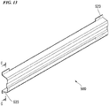
- FIG. 13 is a schematic perspective view showing the door beam 500 (automotive structural member) according to the present embodiment.
- FIG. 14 is a cross-sectional view in a direction of the C-C line in FIG. 13 .
- the door beam 500 includes patch members 530.
- the door beam 500 is long in one direction and includes a door beam main body 520 (first steel sheet member) and a pair of patch members 530 (second steel sheet members) joined to the door beam main body 520.
- the door beam 500 is disposed in a door of an automobile (not shown) by spot-welding inner surfaces 523a of flange portions 523 of the door beam main body 520 to the door of the automobile.
- the door beam main body 520 of the door beam 500 is a steel sheet having a sheet thickness of 0.8 to 2.0 mm and a tensile strength of 980 MPa or higher.
- the door beam main body 520 has a hat-like cross-section which is perpendicular to the longitudinal direction and includes a main wall portion 521, a pair of standing wall portions 522 that stands from both ends 521a of the main wall portion 521, and a pair of the flange portions 523 that is parallel to the main wall portion 521 and extends from one end 522a of each of the standing wall portions 522 so as to separate from the main wall portion 521.
- a steel sheet having a tensile strength of 1,180 MPa or higher is more preferably used as the door beam main body 520.
- the main wall portion 521 of the door beam main body 520 has a protrusion portion 524 which is provided in the widthwise central portion and protrudes toward the flange portion 523.
- the standing wall portion 522 of the door beam main body 520 has a first inclined portion 525 which is connected to the end 521a of the main wall portion 521 and has a predetermined inclination angle and a second inclined portion 526 which is connected to the first inclined portion 525 and has an inclination angle that is different from the above-described inclination angle.
- the patch member 530 of the door beam 500 is a steel sheet having a sheet thickness of 0.8 to 3.0 mm and a tensile strength of 1,180 MPa or higher.
- the patch member 530 has an L-like cross-sectional shape and has a horizontal wall portion 531 and a side wall portion 532 that stands from one end 531a of the horizontal wall portion 531.
- the patch member 530 is joined to an outer surface of the door beam main body 520 by spot-welding the horizontal wall portion 531 and the main wall portion 521 of the door beam main body 520 and spot-welding the side wall portions 532 and the standing wall portions 522 of the door beam main body 520.
- the spot-welding portion 160 is formed between an outer surface 522b of the standing wall portion 522 of the door beam main body 520 and an inner surface 532a of the side wall portion 532 of the patch member 530
- the spot-welding portion 170 is formed between an outer surface 521b of the main wall portion 521 of the door beam main body 520 and an inner surface 531b of the horizontal wall portion 531 of the patch member 530.
- the patch member 530 a variety of steel sheets such as a hot-stamped material can be used.
- a steel sheet having a tensile strength of 1,180 MPa or higher is more preferably used, and a steel sheet having a tensile strength of 1,500 MPa or higher is still more preferably used.
- the horizontal wall portion 531 of the patch member 530 has a shape that follows the shape of the main wall portion 521 of the door beam main body 520.
- the side wall portion 532 of the patch member 530 has a shape that follows the shape of the standing wall portion 522 of the door beam main body 520. That is, in the door beam 500, the horizontal wall portion 531 of the patch member 530 abuts the main wall portion 521 of the door beam main body 520, and the side wall portion 532 of the patch member 530 abuts the standing wall portion 522 of the door beam main body 520.
- the patch members 530 are joined to the door beam main body 520, and thus it is possible to reinforce the door beam main body 520. Therefore, in a case in which the impact is exerted on the door beam 500, it is possible to prevent the breakage or the like of the standing wall portions 522 of the door beam main body 520.
- the patch members 530 are joined to the door beam main body 520, and thus it is possible to reinforce only necessary portions. Therefore, compared with a case in which the sheet thickness of the entire door beam main body 520 is increased, it is possible to reduce an increase in weight.
- H (mm) represents the distance (height) from the outer surface 523b of the flange portion 523 of the door beam main body 520 to the outer surface 531c of the horizontal wall portion 531 of the patch member 530.
- t (mm) represents the sum of the sheet thickness of the standing wall portion 522 of the door beam main body 520 and the sheet thickness of the side wall portion 532 of the patch member 530.
- H1 (mm) represents the distance (height) from a side end surface 532b (tip end surface) of the side wall portion 532 of the patch member 530 to the outer surface 531c of the horizontal wall portion 531.
- the patch members 530 are joined to the door beam main body 520, and thus the door beam main body 520 is reinforced, and both Expression (1) and Expression (2) are satisfied. Therefore, it is possible to improve the energy absorption efficiency when the impact is exerted.
- the patch members 530 may also be joined to an inner surface of the door beam main body 520 as shown in FIG. 15 .
- Test Nos. 1 to 4 indicate cases in which Expression (1) and/or Expression (2) were not satisfied, that is, comparative examples.
- Test Nos. 5 to 11 indicate cases in which Expression (1) and/or Expression (2) were satisfied, that is, invention examples.
- FIG. 16A and FIG. 16B graphs obtained by plotting the results of Table 1 are shown in FIG. 16A and FIG. 16B .
- the horizontal axis indicates H/t
- the vertical axis indicates the energy absorption amount per unit weight EA/mass (kJ/kg).
- the horizontal axis indicates H1/H
- the vertical axis indicates the energy absorption amount per unit weight EA/mass (kJ/kg).
- the automotive structural member is the center pillar, the bumper, or the door beam.
- the present invention is not limited to automotive structural members, and the present invention may be applied to, for example, side sills.
- the patch member 130 is joined to the inner surface of the center pillar outer 120 of the center pillar 100 .
- the patch members 130 may be joined to both the inner surface and the outer surface of the center pillar outer 120.
- the main wall portion 121 of the center pillar outer 120 has a flat sheet shape; however, similar to the bumper 300, a protrusion portion may be provided in the main wall portion 121 of the center pillar outer 120.
- the main wall portion 321 of the bumper main body 320 has been described, but the main wall portion 321 may have a flat sheet shape.
- the main wall portion 521 may have a flat sheet shape.
- a steel sheet member combination structure an automotive structural member, a center pillar, a bumper, and a door beam which are capable of improving the collision energy absorption efficiency at low costs.
Landscapes
- Engineering & Computer Science (AREA)
- Mechanical Engineering (AREA)
- Chemical & Material Sciences (AREA)
- Combustion & Propulsion (AREA)
- Transportation (AREA)
- General Engineering & Computer Science (AREA)
- Body Structure For Vehicles (AREA)
- Rod-Shaped Construction Members (AREA)
Abstract
Description
- The present invention relates to a steel sheet member combination structure, an automotive structural member, a center pillar, a bumper, and a door beam.
- The present application claims priority on the basis of Japanese Patent Application No.
2015-163063 filed on August 20, 2015 - Structural members constituting automotive bodies play a role of limiting the effect, on the inside of cabins, of impact in cases in which an automobile collides with an oncoming vehicle or an obstacle, an automobile is hit from a side of a vehicle body, or the like. For example, as shown in
FIG. 17A and FIG. 17B , when animpactor 5 collides with a lower portion of a center pillar 1 which is one of structural members constituting an automotive body from a side of a vehicle body, and thus the center pillar receives a load, the lower portion of the center pillar 1 deforms so as to collapse toward the inside of the vehicle body in the width direction. Then, due to this deformation, the center pillar 1 absorbs collision energy from theimpactor 5 and suppresses an upper portion of the center pillar 1 coming inside a cabin, thereby securing the safety of a passenger P. - However, in a case in which the center pillar 1 is broken before the load from the
impactor 5 is sufficiently sustained, the collision energy from theimpactor 5 cannot be sufficiently absorbed, and consequently, the upper portion of the center pillar 1 comes inside the cabin as shown inFIG. 17A . In order to prevent the breakage or the like of the center pillar 1 so as to increase the energy absorption amount, an increase in the sheet thickness of the center pillar 1 can be considered, but an increase in the sheet thickness leads to an increase in the vehicle weight. Therefore, it becomes important to improve the energy absorption efficiency (energy absorption amount per unit weight) when there is collision. - Patent Document 1 discloses a technique in which a foamed material is provided in a center pillar, thereby increasing the initial reactive force to collision from a side of a vehicle body, suppressing the deformation of the center pillar coming inside a cabin due to collision, and improving the safety of passengers in the cabin.
- In addition, Patent Document 2 and Patent Document 3 disclose techniques in which a vulnerable portion such as a hole or a recess bead is formed in a lower portion of a center pillar, thereby inducing deformation due to collision mainly in a lower side portion of a vehicle body, suppressing the deformation coming inside a cabin, and improving the safety of passengers in the cabin.
-
- [Patent Document 1] Japanese Unexamined Patent Application, First Publication No.
2007-308114 - [Patent Document 2] Japanese Patent No.
3173539 - [Patent Document 3] Japanese Unexamined Patent Application, First Publication No.
2010-095176 - However, in Patent Document 1, raw materials and manufacturing steps become complex, and thus manufacturing costs increase, and the energy absorption amount by the foamed material cannot be said to be sufficient. As a result, in order to improve the energy absorption efficiency in Patent Document 1, a large amount of a foamed material becomes necessary, and the manufacturing costs significantly increase.
- In addition, in Patent Document 2 and Patent Document 3, there is a possibility that the vulnerable portion such as a hole may break during collision, and there is a possibility that deformation may concentrate in the vulnerable portion and thus cause local deformation. Therefore, in Patent Document 2 and Patent Document 3, the amount of absorbable energy becomes small, and consequently, it is difficult to improve the energy absorption efficiency.
- The present invention has been made in consideration of the above-described circumstances, and an object of the present invention is to provide a steel sheet member combination structure, an automotive structural member, a center pillar, a bumper, and a door beam which are capable of improving the collision energy absorption efficiency at low costs.
- In order to achieve the above-described object, the present invention employs the followings.
- (1) A steel sheet member combination structure according to a first aspect of the present invention includes a first steel sheet member having a main wall portion, a standing wall portion that stands from an end edge of the main wall portion, and a flange portion that extends parallel to the main wall portion from an end edge of the standing wall portion; and a second steel sheet member that is joined to at least one of an inner surface or an outer surface of the first steel sheet member and has a horizontal wall portion that abuts the main wall portion and a side wall portion that abuts the standing wall portion, in which, when larger one of a distance between an outer surface of the flange portion and an outer surface of the main wall portion and a distance between the outer surface of the flange portion and an outer surface of the horizontal wall portion is defined as H (mm), a sum of a sheet thickness of the standing wall portion and a sheet thickness of the side wall portion is defined as t (mm), and larger one of a distance between a tip end surface of the side wall portion and the outer surface of the main wall portion and a distance between the tip end surface of the side wall portion and the outer surface of the horizontal wall portion is defined as H1 (mm), the first steel sheet member and the second steel sheet member satisfy Expression (a) and Expression (b).


- (2) In the aspect according to (1), the steel sheet member combination structure may further include a first joint portion that joins the standing wall portion of the first steel sheet member and the side wall portion of the second steel sheet member.
- (3) In the aspect according to (1) or (2), the steel sheet member combination structure may further include a second joint portion that joins the main wall portion of the first steel sheet member and the horizontal wall portion of the second steel sheet member.
- (4) In the aspect according to any one of (1) to (3), the second steel sheet member may be a steel sheet having a tensile strength of 980 MPa or higher.
- (5) In the aspect according to (4), the first steel sheet member may be a steel sheet having a tensile strength of 980 MPa or higher.
- (6) An automotive structural member according to a second aspect of the present invention includes the steel sheet member combination structure according to any one of (1) to (5).
- (7) A center pillar according to a third aspect of the present invention is a center pillar having the steel sheet member combination structure according to any one of (1) to (5), the center pillar including a center pillar inner; a center pillar outer that is constituted of the first steel sheet member of the steel sheet member combination structure and that is joined to the center pillar inner; and a patch member that is constituted of the second steel sheet member of the steel sheet member combination structure and that is joined to at least one of an inner surface or an outer surface of the center pillar outer.
- (8) A bumper according to a fourth aspect of the present invention is a bumper having the steel sheet member combination structure according to any one of (1) to (5), the bumper including a baseplate; a bumper main body that is constituted of the first steel sheet member of the steel sheet member combination structure and that is joined to the baseplate; and a patch member that is constituted of the second steel sheet member of the steel sheet member combination structure and that is joined to at least one of an inner surface or an outer surface of the bumper main body.
- (9) A door beam according to a fifth aspect of the present invention is a door beam having the steel sheet member combination structure according to any one of (1) to (5), the door beam including a door beam main body constituted of the first steel sheet member of the steel sheet member combination structure; and a patch member that is constituted of the second steel sheet member of the steel sheet member combination structure and that is joined to at least one of an inner surface or an outer surface of the door beam main body.
- According to the respective aspects of the present invention, it is possible to improve the collision energy absorption efficiency at low costs.
-
-
FIG. 1A is a schematic perspective view showing a center pillar according to a first embodiment of the present invention. -
FIG. 1B is an exploded perspective view of the center pillar, (a) is a view showing a center pillar inner of the center pillar, (b) is a view showing a state in which a center pillar outer is joined to the center pillar inner, and (c) is a view showing a patch member that is joined to the center pillar outer. -
FIG. 2 is a cross-sectional view in a direction of an A-A line inFIG. 1A . -
FIG. 3 is a cross-sectional view in the direction of the A-A line inFIG. 1A and a view showing an example of deformation when a load is applied to the center pillar. -
FIG. 4A is a cross-sectional view showing an example of deformation when a load is applied to a center pillar not satisfying Expression (1). -
FIG. 4B is a cross-sectional view showing an example of deformation when a load is applied to a center pillar not satisfying Expression (2). -
FIG. 5 is a cross-sectional view in the direction of the A-A line inFIG. 1A and a view showing a modification example of the center pillar according to the first embodiment of the present invention. -
FIG. 6 is a cross-sectional view in the direction of the A-A line inFIG. 1A and a view showing a center pillar according to a second embodiment of the present invention. -
FIG. 7 is a cross-sectional view in the direction of the A-A line inFIG. 1A and a view showing a modification example of the center pillar. -
FIG. 8 is a schematic perspective view showing a bumper according to a third embodiment of the present invention. -
FIG. 9 is a cross-sectional view in a direction of a B-B line inFIG. 8 . -
FIG. 10 is a cross-sectional view in the direction of the B-B line inFIG. 8 and a view showing a modification example of the bumper. -
FIG. 11 is a cross-sectional view in the direction of the B-B line inFIG. 8 and a view showing a bumper according to a fourth embodiment of the present invention. -
FIG. 12 is a cross-sectional view in the direction of the B-B line inFIG. 8 and a view showing a modification example of the bumper. -
FIG. 13 is a schematic perspective view showing a door beam according to a fifth embodiment of the present invention. -
FIG. 14 is a cross-sectional view in a direction of a C-C line inFIG. 13 . -
FIG. 15 is a cross-sectional view in the direction of the C-C line inFIG. 13 and a view showing a modification example of the door beam. -
FIG. 16A is a graph showing a relationship between H/t and an energy absorption efficiency. -
FIG. 16B is a graph showing a relationship between H1/H and the energy absorption efficiency. -
FIG. 17A is a view showing a center pillar of the related art and a cross-sectional view of the center pillar in a cross-section perpendicular to a front and rear direction of a vehicle body. -
FIG. 17B is a cross-sectional view in a direction of a D-D line inFIG. 17A . [Embodiments of the Invention] - Hereinafter, individual embodiments of the present invention will be described in detail with reference to drawings. In the present specification and the drawings, constituent elements having substantially the same functional constitution will be given the same reference symbol and the description thereof will not be repeated.
-
FIG. 1A is a schematic perspective view showing a center pillar 100 (automotive structural member) according to a first embodiment of the present invention. In addition,FIG. 1B is an exploded perspective view of thecenter pillar 100, (a) is a view showing a center pillar inner 110, (b) is a view showing a state in which a center pillar outer 120 is joined to the center pillar inner 110, and (c) is a view showing apatch member 130 that is joined to the center pillar outer 120. In addition,FIG. 2 is a cross-sectional view in a direction of the A-A line inFIG. 1A . - As shown in
FIG. 1A and FIG. 1B , thecenter pillar 100 is long in one direction and includes the center pillar inner 110, the center pillar outer 120 (first steel sheet member) joined to the center pillar inner 110, and the patch member 130 (second steel sheet member) joined to the center pillar outer 120. In addition, thecenter pillar 100 is disposed on a side of an automotive body in the vertical direction. - In addition, as shown in
FIG. 2 , a cross-section of thecenter pillar 100 which is perpendicular to the longitudinal direction is a hollow cross-section, and, when an impact F is exerted from a side of a vehicle body, the center pillar receives a load from the impact F, bending-deforms, and absorbs collision energy. - As shown in
FIG. 2 , the center pillar inner 110 of thecenter pillar 100 has a flat sheet shape. In addition, the center pillar inner 110 is a steel sheet having, for example, a sheet thickness of 0.6 to 1.6 mm and a tensile strength of 980 MPa or higher. - Meanwhile, as the center pillar inner 110, a steel sheet having a tensile strength of 1,180 MPa or higher is more preferably used.
- The center pillar outer 120 of the
center pillar 100 is a steel sheet having a sheet thickness of 0.8 to 2.0 mm and a tensile strength of 980 MPa or higher. In addition, as shown inFIG. 2 , the center pillar outer 120 has a hat-like cross-section which is perpendicular to the longitudinal direction and includes amain wall portion 121 facing the center pillar inner 110, a pair of standingwall portions 122 that vertically stands from bothends 121a (both end edges) of themain wall portion 121, and a pair offlange portions 123 that is parallel to themain wall portion 121 and extends from oneend 122a (end edge) of each of the standingwall portions 122 so as to separate from themain wall portion 121. - Meanwhile, as the center pillar outer 120, a steel sheet having a tensile strength of 1,180 MPa or higher is more preferably used.
- In addition, as shown in
FIG. 2 , the center pillar outer 120 is joined to anouter surface 110a (a surface toward the outside of the vehicle body) of the center pillar inner 110 by spot-welding theflange portions 123. In other words, spot-weldingportions 150 are provided between theouter surface 110a of the center pillar inner 110 andinner surfaces 123a of theflange portions 123 of the center pillar outer 120. Meanwhile, the center pillar inner 110 and theflange portions 123 of the center pillar outer 120 may be joined together by means of, for example, laser welding, brazing, or the like instead of spot welding. - In addition, the
patch member 130 of thecenter pillar 100 is a steel sheet having a sheet thickness of 0.8 to 3.0 mm and a tensile strength of 980 MPa or higher. In addition, as shown inFIG. 2 , thepatch member 130 has a channel-like cross-sectional shape and includes ahorizontal wall portion 131 and a pair ofside wall portions 132 that vertically stands from bothends 131a (both end edges) of thehorizontal wall portion 131. - In addition, the
patch member 130 is joined to an outer surface of the center pillar outer 120 by spot-welding theside wall portions 132 and the standingwall portions 122 of the center pillar outer 120 and spot-welding thehorizontal wall portion 131 and themain wall portion 121 of the center pillar outer 120. In other words, spot-welding portions 160 (first joint portions) are formed betweenouter surfaces 122b of the standingwall portions 122 of the center pillar outer 120 andinner surfaces 132a of theside wall portions 132 of thepatch member 130, and spot-welding portions 170 (second joint portions) are formed between anouter surface 121b of themain wall portion 121 of the center pillar outer 120 and aninner surface 131b of thehorizontal wall portion 131 of thepatch member 130. Meanwhile, the center pillar outer 120 and thepatch member 130 may be joined together by means of, for example, laser welding, brazing, or the like instead of spot welding. - As the
patch member 130, a variety of steel sheets such as a hot-stamped material can be used. In addition, as thepatch member 130, a steel sheet having a tensile strength of 1,180 MPa or higher is more preferably used, and a steel sheet having a tensile strength of 1,500 MPa or higher is still more preferably used. - The
horizontal wall portion 131 of thepatch member 130 has a shape that follows the shape of themain wall portion 121 of the center pillar outer 120. In addition, theside wall portion 132 of thepatch member 130 has a shape that follows the shape of the standingwall portion 122 of the center pillar outer 120. That is, in thecenter pillar 100, thehorizontal wall portion 131 of thepatch member 130 abuts themain wall portion 121 of the center pillar outer 120, and theside wall portions 132 of thepatch member 130 abut the standingwall portions 122 of the center pillar outer 120. - As described above, in the
center pillar 100, thepatch member 130 is joined to the center pillar outer 120, and thus it is possible to reinforce the center pillar outer 120. In addition, thepatch member 130 is joined to the center pillar outer 120, and thus it is possible to reinforce only necessary portions. Therefore, compared with a case in which the sheet thickness of the entire center pillar outer 120 is increased, it is possible to reduce an increase in weight. - As shown in
FIG. 2 , at least a portion of the spot-weldingportion 160 is preferably formed in a range of L1 (mm) from aside end surface 132b (tip end surface) of theside wall portion 132 of thepatch member 130. Here, L1 represents 40% of the height (the distance from theside end surface 132b of theside wall portion 132 to anouter surface 131c of the horizontal wall portion 131) of theside wall portion 132 of thepatch member 130. That is, for example, in a case in which the height of theside wall portion 132 of thepatch member 130 is 60 mm, at least a portion of the spot-weldingportion 160 is preferably formed in a range of L1=24 mm from theside end surface 132b of theside wall portion 132 of thepatch member 130. - At least a portion of the spot-welding
portion 170 is preferably formed in a range of L2 (mm) from theinner surface 132a of theside wall portion 132. Here, similar to L1, L2 represents 40% of the height (the distance from theside end surface 132b of theside wall portion 132 to theouter surface 131c of the horizontal wall portion 131) of theside wall portion 132 of thepatch member 130. Meanwhile, in a case in which an R portion is provided between themain wall portion 121 and the standingwall portion 122, at least a portion of the spot-weldingportion 170 is preferably formed in a range of L2 from an R stop. - Next, individual parameters of the
center pillar 100 will be described. In thecenter pillar 100, the center pillar outer 120 and thepatch member 130 satisfy both Expressions (1) and (2) below.

- Here, as shown in
FIG. 2 , H (mm) represents larger one of the distance between anouter surface 123b of theflange portion 123 and theouter surface 121b of themain wall portion 121 and the distance between theouter surface 123b of theflange portion 123 and theouter surface 131c of thehorizontal wall portion 131. That is, in thecenter pillar 100, since thepatch member 130 is joined to the outer surface of the center pillar outer 120, the H represents the distance (height) from theouter surface 123b of theflange portion 123 of the center pillar outer 120 to theouter surface 131c of thehorizontal wall portion 131 of thepatch member 130. - In addition, t (mm) represents the sum of the sheet thickness of the standing
wall portion 122 of the center pillar outer 120 and the sheet thickness of theside wall portion 132 of thepatch member 130. - In addition, H1 (mm) represents a larger distance (height) of the distance between the
side end surface 132b of theside wall portion 132 and theouter surface 121b of themain wall portion 121 and the distance between theside end surface 132b of theside wall portion 132 and theouter surface 131c of thehorizontal wall portion 131. That is, in thecenter pillar 100, since thepatch member 130 is joined to the outer surface of the center pillar outer 120, the H1 represents the distance (height) from theside end surface 132b of theside wall portion 132 to theouter surface 131c of thehorizontal wall portion 131. - In the
center pillar 100, as described below, thepatch member 130 is joined to the center pillar outer 120, and thus the center pillar outer 120 is reinforced, and both Expression (1) and Expression (2) are satisfied. Therefore, it is possible to improve the energy absorption efficiency when the impact F is exerted. Here, the reason for establishing Expression (1) and Expression (2) is as described below. - In a case in which Expression (1) is not satisfied ((H/t) > 20.0): The standing
wall portions 122 of the center pillar outer 120 easily buckling-deform, and there is a concern that the standingwall portions 122 may break before sufficiently sustaining the load from the impact. In this case, the load after breakage is received by the center pillar inner 110, themain wall portion 121 of the center pillar outer 120, and thehorizontal wall portion 131 of thepatch member 130. In such a case, when thecenter pillar 100 is seen in the longitudinal direction, there is a concern that thecenter pillar 100 may deform in a wide range including locations away from an impact point and may come inside the cabin. - In a case in which the lower limit value of Expression (2) is not satisfied (0.6 > (H1/H)): The standing
wall portions 122 of the center pillar outer 120 are incapable of sufficiently obtaining the reinforcement effect of theside wall portions 132 of thepatch member 130, and thus the standingwall portions 122 easily buckling-deform, and there is a concern that the standingwall portions 122 may break before sufficiently sustaining the load from the impact. In this case, the load after breakage is received by the center pillar inner 110, themain wall portion 121 of the center pillar outer 120, and thehorizontal wall portion 131 of thepatch member 130. In such a case, when thecenter pillar 100 is seen in the longitudinal direction, there is a concern that thecenter pillar 100 may deform in a wide range including locations away from an impact point and may come inside the cabin. - In a case in which the upper limit value of Expression (2) is not satisfied ((H1/H) > 1.0): This case cannot occur in a dimensional sense, and thus it is not possible to join the
patch member 130 to the center pillar outer 120. Therefore, it is not possible to sufficiently obtain the reinforcement effect of thepatch member 130, and thus the standingwall portions 122 easily buckling-deform, and there is a concern that the standingwall portions 122 may break before sufficiently sustaining the load from the impact. - In a case in which both Expression (1) and Expression (2) are satisfied: This case is within the scope of the present invention, and it is possible to prevent the standing
wall portions 122 of the center pillar outer 120 from breaking due to impact. In addition, collision energy can be reliably absorbed by the deformation operation of the standingwall portions 122 of the center pillar outer 120 and theside wall portions 132 of thepatch member 130. - Meanwhile, regarding Expression (1), from the viewpoint of a breakage-preventing effect, the value of H/t is preferably smaller. For example, H/t is preferably 17.5 or less, more preferably 15.0 or less, and still more preferably 12.5 or less. On the other hand, the lower limit of H/t is not particularly limited, but H/t is, for example, 5.0 or more.
- In addition, regarding Expression (2), from the viewpoint of the breakage-preventing effect, H1/H is preferably 0.7 or more, and more preferably 0.8 or more.
- An example of deformation occurring in a case in which the impact F is exerted on the
center pillar 100 satisfying both Expressions (1) and (2) is shown inFIG. 3 . InFIG. 3 , since thecenter pillar 100 satisfies both Expressions (1) and (2), the standingwall portions 122 of the center pillar outer 120 are sufficiently reinforced by thepatch member 130, and it is possible to prevent the standingwall portions 122 from easily buckling-deforming. - On the other hand, an example of deformation occurring in a case in which the impact F is exerted on a
center pillar 50 not satisfying Expression (1) is shown inFIG. 4A . InFIG. 4A , since thecenter pillar 50 does not satisfy Expression (1), it is not possible to sufficiently reinforce the standingwall portions 122 of the center pillar outer 120 using thepatch member 130, and the standingwall portions 122 easily buckling-deform. - In addition, an example of deformation occurring in a case in which the impact F is exerted on a
center pillar 60 not satisfying Expression (2) is shown inFIG. 4B . InFIG. 4B , since thecenter pillar 60 does not satisfy Expression (2), it is not possible to sufficiently obtain the reinforcement effect of thepatch member 130, and the standingwall portions 122 easily buckling-deform. - As described above, according to the
center pillar 100 of the present embodiment, since thepatch member 130 is joined to the center pillar outer 120, it is possible to reinforce only necessary portions without increasing the sheet thickness of the entire center pillar outer 120. Therefore, it is possible to reinforce the center pillar outer 120 while suppressing an increase in the weight of thecenter pillar 100. In addition, since the center pillar outer 120 and thepatch member 130 satisfy both Expression (1) and Expression (2), in a case in which an impact is exerted from a side of a vehicle body, it is possible to prevent the breakage of the standingwall portions 122 of the center pillar outer 120. Therefore, it is possible to improve the collision energy absorption efficiency at low costs. - Meanwhile, in the
center pillar 100, a predetermined distance D (mm) is preferably provided between theside end surface 132b of theside wall portion 132 of thepatch member 130 and theouter surface 123b of theflange portion 123 of the center pillar outer 120 as shown inFIG. 2 (D>0). In other words, regarding Expression (2), H1/H is preferably less than 1.0 ((H1/H) < 1.0). In this case, since a gap is generated between theside end surface 132b of theside wall portion 132 of thepatch member 130 and theouter surface 123b of theflange portion 123 of the center pillar outer 120, it is possible to prevent theside end surface 132b of thepatch member 130 from being confined in theflange portion 123 of the center pillar outer 120 when thepatch member 130 is deformed by the impact F. Therefore, it is possible to cause theside wall portions 132 of thepatch member 130 to reliably follow the deformation of the standingwall portions 122 of the center pillar outer 120, and consequently, it is possible to prevent the peeling of the spot-weldingportions 160. - Meanwhile, the distance D is more preferably set to, for example, 10% or more of H. That is, regarding Expression (2), H1/H is more preferably 0.9 or less.
- In the present embodiment, a case in which the channel-
like patch member 130 is joined to the center pillar outer 120 has been described. However, a pair ofpatch members 140 having an L-like cross-sectional shape may be joined to the center pillar outer 120 as shown inFIG. 5 . In this case, the volume of thehorizontal wall portions 131 of thepatch members 140 which abut themain wall portion 121 of the center pillar outer 120 becomes small, and thus it is possible to reduce the weight of thecenter pillar 100. - Next, a
center pillar 200 according to a second embodiment of the present invention will be described. -
FIG. 6 is a horizontal cross-sectional view showing thecenter pillar 200 according to the present embodiment. In thecenter pillar 100 according to the first embodiment, a case in which thepatch member 130 is joined to the outer surface of the center pillar outer 120 has been described. In contrast, in thecenter pillar 200 according to the present embodiment, thepatch member 130 is joined to an inner surface of the center pillar outer 120 as shown inFIG. 6 . - In the
center pillar 200, as shown inFIG. 6 , thehorizontal wall portion 131 of thepatch member 130 is joined to aninner surface 121c of themain wall portion 121 of the center pillar outer 120 using the spot-weldingportions 170, and theside wall portions 132 of thepatch member 130 are joined toinner surfaces 122c of the standingwall portions 122 of the center pillar outer 120 using the spot-weldingportions 160. - That is, the
center pillar 200 according to the present embodiment is, similar to thecenter pillar 100 according to the first embodiment, capable of reinforcing the center pillar outer 120. In addition, thecenter pillar 200 is, similar to thecenter pillar 100 according to the first embodiment, capable of improving the collision energy absorption efficiency by satisfying Expression (1) and Expression (2). - Meanwhile, regarding Expression (1) and Expression (2), in the
center pillar 200, since thepatch member 130 is joined to the inner surface of the center pillar outer 120, H (mm) becomes the distance (height) from theouter surface 123b of theflange portion 123 of the center pillar outer 120 to theouter surface 121b of themain wall portion 121 of the center pillar outer 120. In addition, H1 (mm) becomes the distance (height) from theside end surface 132b of theside wall portion 132 of thepatch member 130 to theouter surface 121b of themain wall portion 121 of the center pillar outer 120. - In the present embodiment, a case in which the channel-
like patch member 130 is joined to the inner surface of the center pillar outer 120 has been described. However, the pair ofpatch members 140 having an L-like cross-sectional shape may be joined to the inner surface of the center pillar outer 120 as shown inFIG. 7 . In this case, the volume of thehorizontal wall portions 131 of thepatch members 140 which abut themain wall portion 121 of the center pillar outer 120 becomes small, and thus it is possible to reduce the weight of thecenter pillar 200. - Next, a
bumper 300 according to a third embodiment of the present invention will be described. -
FIG. 8 is a schematic perspective view showing the bumper 300 (automotive structural member) according to a third embodiment of the present invention. In addition,FIG. 9 is a cross-sectional view in a direction of the B-B line inFIG. 8 . In the first embodiment and the second embodiment, cases in which thecenter pillar 100 or thecenter pillar 200 includes thepatch member 130 have been described. In contrast, in the present embodiment, thebumper 300 includes a pair ofpatch members 330. - As shown in
FIG. 8 andFIG. 9 , thebumper 300 is long in one direction and includes abaseplate 310, a bumper main body 320 (first steel sheet member) joined to thebaseplate 310, and the pair of patch members 330 (second steel sheet members) joined to the bumpermain body 320. In addition, thebumper 300 is disposed on the front side or rear side of an automotive body. - In addition, as shown in
FIG. 9 , a cross-section of thebumper 300 which is perpendicular to the longitudinal direction is a hollow cross-section, and, when the impact F is exerted from the front side or rear side of a vehicle body, the bumper receives a load from the impact F, bending-deforms, and absorbs collision energy. - The
baseplate 310 of thebumper 300 has a flat sheet shape. In addition, thebaseplate 310 of thebumper 300 is a steel sheet having, for example, a sheet thickness of 1.4 mm and a tensile strength of 980 MPa or higher. - Meanwhile, as the
baseplate 310, a steel sheet of 1,180 MPa or higher is more preferably used. - As shown in
FIG. 9 , the bumpermain body 320 of thebumper 300 has a hat-like cross-section which is perpendicular to the longitudinal direction and is a steel sheet having a sheet thickness of 0.8 to 2.0 mm and a tensile strength of 980 MPa or higher. In addition, the bumpermain body 320 includes amain wall portion 321 facing thebaseplate 310, a pair of standingwall portions 322 that vertically stands from bothends 321a of themain wall portion 321, and a pair offlange portions 323 that is parallel to themain wall portion 321 and extends from oneend 322a of each of the standingwall portions 322 so as to separate from themain wall portion 321. - Meanwhile, as the bumper
main body 320, a steel sheet of 1,180 MPa or higher is more preferably used. - The
main wall portion 321 of the bumpermain body 320 has aprotrusion portion 324 that protrudes toward thebaseplate 310 in a widthwise central portion. In addition, theprotrusion portion 324 has a pair of center-reinforcingwall portions 324a that stands toward thebaseplate 310 from themain wall portion 321 and aflat surface portion 324b that connects the pair of center-reinforcingwall portions 324a. - In addition, the bumper
main body 320 is joined to anouter surface 310a (a surface toward the outside of the vehicle body) of thebaseplate 310 by spot-welding theflange portions 323. In other words, the spot-weldingportions 150 are provided between theouter surface 310a of thebaseplate 310 andinner surfaces 323a of theflange portions 323 of the bumpermain body 320. - The
patch member 330 is a steel sheet having a sheet thickness of 0.8 to 3.0 mm and a tensile strength of 980 MPa or higher. In addition, thepatch member 330 has a channel-like cross-sectional shape that is perpendicular to the longitudinal direction and includes ahorizontal wall portion 331, aside wall portion 332 that vertically stands from oneend 331a of thehorizontal wall portion 331, and a holdingwall portion 333 that stands from theother end 331d of thehorizontal wall portion 331. - Meanwhile, as the
patch member 330, a variety of steel sheets such as a hot-stamped material can be used. In addition, as thepatch member 330, a steel sheet having a tensile strength of 1,180 MPa or higher is more preferably used, and a steel sheet having a tensile strength of 1,500 MPa or higher is still more preferably used. - The
patch member 330 is joined to the outer surface of the bumpermain body 320 by spot-welding theside wall portion 332 and the standingwall portion 322 of the bumpermain body 320, spot-welding thehorizontal wall portion 331 and themain wall portion 321 of the bumpermain body 320, and spot-welding the holdingwall portion 333 and the center-reinforcingwall portion 324a of the bumpermain body 320. In other words, the spot-weldingportion 160 is formed between anouter surface 322b of the standingwall portion 322 of the bumpermain body 320 and aninner surface 332a of theside wall portion 332 of thepatch member 330, the spot-weldingportions 170 are formed between anouter surface 321b of themain wall portion 321 of the bumpermain body 320 and aninner surface 331b of thehorizontal wall portion 331 of thepatch member 330, and a spot-weldingportion 380 is formed between an outer surface 324a1 of the center-reinforcingwall portion 324a of the bumpermain body 320 and aninner surface 333a of the holdingwall portion 333 of thepatch member 330. - The
horizontal wall portion 331 of thepatch member 330 has a shape that follows the shape of themain wall portion 321 of the bumpermain body 320. In addition, theside wall portion 332 of thepatch member 330 has a shape that follows the shape of the standingwall portion 322 of the bumpermain body 320. In addition, the holdingwall portion 333 of thepatch member 330 has a shape that follows the shape of the center-reinforcingwall portion 324a of the bumpermain body 320. That is, in thebumper 300, thehorizontal wall portion 331 of thepatch member 330 abuts themain wall portion 321 of the bumpermain body 320, theside wall portion 332 of thepatch member 330 abuts the standingwall portion 322 of the bumpermain body 320, and the holdingwall portion 333 of thepatch member 330 abuts the center-reinforcingwall portion 324a of the bumpermain body 320. - As described above, in the
bumper 300, thepatch members 330 are joined to the bumpermain body 320, and thus it is possible to reinforce the bumpermain body 320. Therefore, in a case in which the impact F is exerted on thebumper 300, it is possible to prevent the breakage or the like of the standingwall portions 322 of the bumpermain body 320. In addition, the bumpermain body 320 is reinforced by thepatch members 330, and thus it is possible to reinforce only necessary portions. Therefore, compared with a case in which the sheet thickness of the entire bumpermain body 320 is increased, it is possible to reduce an increase in weight. - Next, individual parameters of the
bumper 300 will be described. In thebumper 300, the bumpermain body 320 and thepatch member 330 satisfy both Expressions (1) and (2) which have been described in the first embodiment.

- Here, similar to the case of the first embodiment, H (mm) represents the distance (height) from the
outer surface 323b of theflange portion 323 of the bumpermain body 320 to theouter surface 331c of thehorizontal wall portion 331 of thepatch member 330. In addition, t (mm) represents the sum of the sheet thickness of the standingwall portion 322 of the bumpermain body 320 and the sheet thickness of theside wall portion 332 of thepatch member 330. In addition, H1 (mm) represents the distance (height) from aside end surface 332b (tip end surface) of theside wall portion 332 of thepatch member 330 to theouter surface 331c of thehorizontal wall portion 331. - In the
bumper 300, similar to the case of the first embodiment, thepatch members 330 are joined to the bumpermain body 320, and thus the bumpermain body 320 is reinforced, and both Expression (1) and Expression (2) are satisfied. Therefore, it is possible to improve the energy absorption efficiency when the impact F is exerted. - In the present embodiment, a case in which the channel-
like patch members 330 are joined to the bumpermain body 320 has been described. However, a pair ofpatch members 340 and a pair ofpatch members 345 which have an L-like cross-sectional shape may be joined to the bumpermain body 320 as shown inFIG. 10 . In this case, the volume of thehorizontal wall portions 331 of thepatch members 330 which abut themain wall portion 321 of the bumpermain body 320 becomes small, and thus it is possible to further reduce the weight of thebumper 300. - Next, a
bumper 400 according to a fourth embodiment of the present invention will be described. -
FIG. 11 is a horizontal cross-sectional view showing abumper 400 according to the present embodiment. In thebumper 300 of the third embodiment, a case in which thepatch members 330 are joined to the outer surface of the bumpermain body 320 has been described. In contrast, in thebumper 400 according to the present embodiment, thepatch members 330 are joined to an inner surface of the bumpermain body 320 as shown inFIG. 11 . - As shown in
FIG. 11 , in thebumper 400, thehorizontal wall portion 331 of thepatch member 330 is joined to an inner surface of themain wall portion 321 of the bumpermain body 320 using the spot-weldingportions 170, and theside wall portion 332 of thepatch member 330 is joined to an inner surface of the standingwall portion 322 of the bumpermain body 320 using the spot-weldingportion 160. - That is, in the
bumper 400 according to the present embodiment, similar to thebumper 300 according to the third embodiment, it is possible to reinforce the bumpermain body 320. In addition, thebumper 400 is, similar to thebumper 300 according to the third embodiment, capable of improving the collision energy absorption efficiency by satisfying Expression (1) and Expression (2). - Meanwhile, regarding Expression (1) and Expression (2), in the present embodiment, since the
patch member 330 is joined to the inner surface of the bumpermain body 320, H (mm) becomes the distance (height) from theouter surface 323b of theflange portion 323 of the bumpermain body 320 to theouter surface 321b of themain wall portion 321 of the bumpermain body 320. In addition, H1 (mm) becomes the distance (height) from theside end surface 332b of theside wall portion 332 of thepatch member 330 to theouter surface 321b of themain wall portion 321 of the bumpermain body 320. - In the present embodiment, a case in which the channel-
like patch members 330 are joined to the inner surface of the bumpermain body 320 has been described. However, the pair ofpatch members 340 and the pair ofpatch members 345 which have an L-like cross-sectional shape may be joined to the bumpermain body 320 as shown inFIG. 12 . In this case, the volume of thehorizontal wall portions 331 of thepatch members main wall portion 321 of the bumpermain body 320 becomes small, and thus it is possible to further reduce the weight of thebumper 400. - Next, a
door beam 500 according to a fifth embodiment of the present invention will be described. -
FIG. 13 is a schematic perspective view showing the door beam 500 (automotive structural member) according to the present embodiment. In addition,FIG. 14 is a cross-sectional view in a direction of the C-C line inFIG. 13 . In the first embodiment, a case in which thecenter pillar 100 includes thepatch member 130 has been described. In contrast, in the present embodiment, thedoor beam 500 includespatch members 530. - As shown in
FIG. 13 andFIG. 14 , thedoor beam 500 is long in one direction and includes a door beam main body 520 (first steel sheet member) and a pair of patch members 530 (second steel sheet members) joined to the door beammain body 520. In addition, thedoor beam 500 is disposed in a door of an automobile (not shown) by spot-weldinginner surfaces 523a offlange portions 523 of the door beammain body 520 to the door of the automobile. - The door beam
main body 520 of thedoor beam 500 is a steel sheet having a sheet thickness of 0.8 to 2.0 mm and a tensile strength of 980 MPa or higher. In addition, as shown inFIG. 14 , the door beammain body 520 has a hat-like cross-section which is perpendicular to the longitudinal direction and includes amain wall portion 521, a pair of standingwall portions 522 that stands from bothends 521a of themain wall portion 521, and a pair of theflange portions 523 that is parallel to themain wall portion 521 and extends from oneend 522a of each of the standingwall portions 522 so as to separate from themain wall portion 521. - Meanwhile, as the door beam
main body 520, a steel sheet having a tensile strength of 1,180 MPa or higher is more preferably used. - The
main wall portion 521 of the door beammain body 520 has aprotrusion portion 524 which is provided in the widthwise central portion and protrudes toward theflange portion 523. In addition, the standingwall portion 522 of the door beammain body 520 has a firstinclined portion 525 which is connected to theend 521a of themain wall portion 521 and has a predetermined inclination angle and a secondinclined portion 526 which is connected to the firstinclined portion 525 and has an inclination angle that is different from the above-described inclination angle. - The
patch member 530 of thedoor beam 500 is a steel sheet having a sheet thickness of 0.8 to 3.0 mm and a tensile strength of 1,180 MPa or higher. In addition, as shown inFIG. 14 , thepatch member 530 has an L-like cross-sectional shape and has ahorizontal wall portion 531 and aside wall portion 532 that stands from oneend 531a of thehorizontal wall portion 531. - In addition, the
patch member 530 is joined to an outer surface of the door beammain body 520 by spot-welding thehorizontal wall portion 531 and themain wall portion 521 of the door beammain body 520 and spot-welding theside wall portions 532 and the standingwall portions 522 of the door beammain body 520. In other words, the spot-weldingportion 160 is formed between anouter surface 522b of the standingwall portion 522 of the door beammain body 520 and aninner surface 532a of theside wall portion 532 of thepatch member 530, and the spot-weldingportion 170 is formed between anouter surface 521b of themain wall portion 521 of the door beammain body 520 and aninner surface 531b of thehorizontal wall portion 531 of thepatch member 530. - Meanwhile, as the
patch member 530, a variety of steel sheets such as a hot-stamped material can be used. In addition, as thepatch member 530, a steel sheet having a tensile strength of 1,180 MPa or higher is more preferably used, and a steel sheet having a tensile strength of 1,500 MPa or higher is still more preferably used. - The
horizontal wall portion 531 of thepatch member 530 has a shape that follows the shape of themain wall portion 521 of the door beammain body 520. In addition, theside wall portion 532 of thepatch member 530 has a shape that follows the shape of the standingwall portion 522 of the door beammain body 520. That is, in thedoor beam 500, thehorizontal wall portion 531 of thepatch member 530 abuts themain wall portion 521 of the door beammain body 520, and theside wall portion 532 of thepatch member 530 abuts the standingwall portion 522 of the door beammain body 520. - As described above, in the
door beam 500, thepatch members 530 are joined to the door beammain body 520, and thus it is possible to reinforce the door beammain body 520. Therefore, in a case in which the impact is exerted on thedoor beam 500, it is possible to prevent the breakage or the like of the standingwall portions 522 of the door beammain body 520. In addition, thepatch members 530 are joined to the door beammain body 520, and thus it is possible to reinforce only necessary portions. Therefore, compared with a case in which the sheet thickness of the entire door beammain body 520 is increased, it is possible to reduce an increase in weight. - Next, individual parameters of the
door beam 500 will be described. In thedoor beam 500, the door beammain body 520 and thepatch member 530 satisfy both Expressions (1) and (2) which have been described in the first embodiment.

- Here, similar to the case of the first embodiment, H (mm) represents the distance (height) from the
outer surface 523b of theflange portion 523 of the door beammain body 520 to theouter surface 531c of thehorizontal wall portion 531 of thepatch member 530. In addition, t (mm) represents the sum of the sheet thickness of the standingwall portion 522 of the door beammain body 520 and the sheet thickness of theside wall portion 532 of thepatch member 530. In addition, H1 (mm) represents the distance (height) from aside end surface 532b (tip end surface) of theside wall portion 532 of thepatch member 530 to theouter surface 531c of thehorizontal wall portion 531. - In the
door beam 500, similar to the case of the first embodiment, thepatch members 530 are joined to the door beammain body 520, and thus the door beammain body 520 is reinforced, and both Expression (1) and Expression (2) are satisfied. Therefore, it is possible to improve the energy absorption efficiency when the impact is exerted. - Meanwhile, similar to the case of the first embodiment, the
patch members 530 may also be joined to an inner surface of the door beammain body 520 as shown inFIG. 15 . - Next, examples carried out in order to confirm the action effects of the present invention will be described.
- An FEM analysis of the three-point bending deformation of a hat-like member which simulated the cross-sectional shape (refer to
FIG. 2 ) of thecenter pillar 100 according to the first embodiment was carried out, and the energy absorption amount per unit weight was obtained. Specifically, the hat-like member was supported at two points which were located in the longitudinal direction at a predetermined interval, a predetermined load was applied to the central location of the two points, and the energy absorption amount was obtained. In addition, the energy absorption amount was divided by the weight of the hat-like member, thereby obtaining the energy absorption amount per unit weight. At this time, as the hat-like member, a steel sheet having a tensile strength of 980 MPa was used. - In addition, for comparison, the same analysis was also carried out on cases in which Expression (1) and/or Expression (2) were not satisfied. Meanwhile, in Test Nos. 1 to 11 shown in Table 1, the same conditions were set except for H, t, and H1.
[Table 1] Test No. H (mm) t (mm) H1 (mm) H/t H1/H Satisfaction of Expression (1) Satisfaction of Expression (2) Energy absorption amount EA (kJ) Weight (kg) Energy absorption amount per unit weight EA/mass (kJ/kg) Differentiation 1 50.0 2.0 25.0 25.0 0.50 No No 0.854 2.149 0.397 Comparative Example 2 50.0 2.0 40.0 25.0 0.80 No Yes 0.884 2.291 0.386 Comparative Example 3 50.0 2.0 16.5 25.0 0.33 No No 0.900 2.091 0.430 Comparative Example 4 40.0 2.0 20.0 20.0 0.50 Yes No 0.850 2.030 0.419 Comparative Example 5 10.0 3.0 7.0 3.3 0.70 Yes Yes 1.200 1.937 0.620 Invention Example 6 40.0 2.0 25.0 20.0 0.63 Yes Yes 1.100 2.069 0.532 Invention Example 7 10.0 2.0 7.0 5.0 0.70 Yes Yes 1.040 1.599 0.650 Invention Example 8 35.0 2.0 25.0 17.5 0.71 Yes Yes 1.100 1.988 0.553 Invention Example 9 30.0 2.0 25.0 15.0 0.83 Yes Yes 1.100 1.952 0.564 Invention Example 10 25.0 2.0 20.0 12.5 0.80 Yes Yes 1.150 1.874 0.614 Invention Example 11 20.0 2.0 15.0 10.0 0.75 Yes Yes 1.148 1.795 0.640 Invention Example - In Table 1, Test Nos. 1 to 4 indicate cases in which Expression (1) and/or Expression (2) were not satisfied, that is, comparative examples. On the other hand, Test Nos. 5 to 11 indicate cases in which Expression (1) and/or Expression (2) were satisfied, that is, invention examples.
- In addition, graphs obtained by plotting the results of Table 1 are shown in
FIG. 16A and FIG. 16B . Meanwhile, inFIG. 16A , the horizontal axis indicates H/t, and the vertical axis indicates the energy absorption amount per unit weight EA/mass (kJ/kg). In addition, inFIG. 16B , the horizontal axis indicates H1/H, and the vertical axis indicates the energy absorption amount per unit weight EA/mass (kJ/kg). - As shown in Table 1 and shown in
FIG. 16A and FIG. 16B , it could be confirmed that, in the cases in which both Expression (1) and/or Expression (2) were satisfied, the energy absorption amount per unit weight increased compared with the cases in which any one of Expression (1) and Expression (2) was not satisfied and the cases in which both Expression (1) and/or Expression (2) were not satisfied. - While the embodiments of the present invention have been described, but the embodiments are simply examples, and the scope of the present invention is not limited only to the above-described embodiments. The embodiments can be carried out in a variety of other forms and can be omitted, substituted, or modified in various manners within the scope of the gist of the invention. The embodiments or modifications thereof are included in the scope of the invention described in the claims and equivalence thereof as is the case of being included in the scope or gist of the invention.
- For example, in the embodiments, the cases in which the automotive structural member is the center pillar, the bumper, or the door beam have been described. However, the present invention is not limited to automotive structural members, and the present invention may be applied to, for example, side sills.
- In addition, for example, in the first embodiment, the case in which the
patch member 130 is joined to the inner surface of the center pillar outer 120 of thecenter pillar 100 has been described. However, thepatch members 130 may be joined to both the inner surface and the outer surface of the center pillar outer 120. - In addition, for example, in the first embodiment, the case in which the
main wall portion 121 of the center pillar outer 120 has a flat sheet shape has been described; however, similar to thebumper 300, a protrusion portion may be provided in themain wall portion 121 of the center pillar outer 120. In addition, in the third embodiment, the case in which the protrusion portion is provided in themain wall portion 321 of the bumpermain body 320 has been described, but themain wall portion 321 may have a flat sheet shape. In addition, in the fifth embodiment, the case in which the protrusion portion is provided in themain wall portion 521 of the door beammain body 520 has been described, but themain wall portion 521 may have a flat sheet shape. - According to the present invention, it is possible to provide a steel sheet member combination structure, an automotive structural member, a center pillar, a bumper, and a door beam which are capable of improving the collision energy absorption efficiency at low costs.
-
- 100: center pillar (automotive structural member)
- 110: center pillar inner
- 120: center pillar outer (first steel sheet member)
- 121: main wall portion of center pillar outer
- 122: standing wall portion of center pillar outer
- 123: flange portion of center pillar outer
- 130: patch member (second steel sheet member)
- 150: spot-welding portion
- 160: spot-welding portion (first joint portion)
- 170: spot-welding portion (second joint portion)
Claims (9)
- A steel sheet member combination structure comprising:a first steel sheet member having a main wall portion, a standing wall portion that stands from an end edge of the main wall portion, and a flange portion that extends parallel to the main wall portion from an end edge of the standing wall portion; anda second steel sheet member that is joined to at least one of an inner surface or an outer surface of the first steel sheet member and has a horizontal wall portion that abuts the main wall portion and a side wall portion that abuts the standing wall portion,wherein, when larger one of a distance between an outer surface of the flange portion and an outer surface of the main wall portion and a distance between the outer surface of the flange portion and an outer surface of the horizontal wall portion is defined as H (mm),a sum of a sheet thickness of the standing wall portion and a sheet thickness of the side wall portion is defined as t (mm), andlarger one of a distance between a tip end surface of the side wall portion and the outer surface of the main wall portion and a distance between the tip end surface of the side wall portion and the outer surface of the horizontal wall portion is defined as H1 (mm),the first steel sheet member and the second steel sheet member satisfy Expression (1) and Expression (2):


- The steel sheet member combination structure according to Claim 1, further comprising:
a first joint portion that joins together the standing wall portion of the first steel sheet member and the side wall portion of the second steel sheet member. - The steel sheet member combination structure according to Claim 1 or 2, further comprising:
a second joint portion that joins together the main wall portion of the first steel sheet member and the horizontal wall portion of the second steel sheet member. - The steel sheet member combination structure according to any one of Claims 1 to 3,
wherein the second steel sheet member is a steel sheet having a tensile strength of 980 MPa or higher. - The steel sheet member combination structure according to Claim 4,
wherein the first steel sheet member is a steel sheet having a tensile strength of 980 MPa or higher. - An automotive structural member comprising:
the steel sheet member combination structure according to any one of Claims 1 to 5. - A center pillar having the steel sheet member combination structure according to any one of Claims 1 to 5, the center pillar comprising:a center pillar inner;a center pillar outer that is constituted of the first steel sheet member of the steel sheet member combination structure and that is joined to the center pillar inner; anda patch member that is constituted of the second steel sheet member of the steel sheet member combination structure and that is joined to at least one of an inner surface or an outer surface of the center pillar outer.
- A bumper having the steel sheet member combination structure according to any one of Claims 1 to 5, the bumper comprising:a baseplate;a bumper main body that is constituted of the first steel sheet member of the steel sheet member combination structure and that is joined to the baseplate; anda patch member that is constituted of the second steel sheet member of the steel sheet member combination structure and that is joined to at least one of an inner surface or an outer surface of the bumper main body.
- A door beam having the steel sheet member combination structure according to any one of Claims 1 to 5, the door beam comprising:a door beam main body constituted of the first steel sheet member of the steel sheet member combination structure; anda patch member that is constituted of the second steel sheet member of the steel sheet member combination structure and that is joined to at least one of an inner surface or an outer surface of the door beam main body.
Applications Claiming Priority (2)
| Application Number | Priority Date | Filing Date | Title |
|---|---|---|---|
| JP2015163063 | 2015-08-20 | ||
| PCT/JP2016/074241 WO2017030191A1 (en) | 2015-08-20 | 2016-08-19 | Steel sheet member combination structure, automobile structural member, center pillar, bumper, and door beam |
Publications (3)
| Publication Number | Publication Date |
|---|---|
| EP3339139A1 true EP3339139A1 (en) | 2018-06-27 |
| EP3339139A4 EP3339139A4 (en) | 2019-04-10 |
| EP3339139B1 EP3339139B1 (en) | 2022-01-26 |
Family
ID=58050908
Family Applications (1)
| Application Number | Title | Priority Date | Filing Date |
|---|---|---|---|
| EP16837180.5A Active EP3339139B1 (en) | 2015-08-20 | 2016-08-19 | Steel sheet member combination structure, automobile structural member, center pillar, bumper, and door beam |
Country Status (10)
| Country | Link |
|---|---|
| US (1) | US10486750B2 (en) |
| EP (1) | EP3339139B1 (en) |
| JP (1) | JP6604383B2 (en) |
| KR (1) | KR102059495B1 (en) |
| CN (1) | CN107922010B (en) |
| BR (1) | BR112018002407A2 (en) |
| CA (1) | CA2995048C (en) |
| MX (1) | MX391805B (en) |
| RU (1) | RU2677750C1 (en) |
| WO (1) | WO2017030191A1 (en) |
Cited By (2)
| Publication number | Priority date | Publication date | Assignee | Title |
|---|---|---|---|---|
| WO2020224819A1 (en) * | 2019-05-07 | 2020-11-12 | Gestamp Hardtech Ab | Corner patch |
| RU2805332C2 (en) * | 2019-05-07 | 2023-10-16 | Аутотек Инджиниринг С.Л. | Corner piece |
Families Citing this family (11)
| Publication number | Priority date | Publication date | Assignee | Title |
|---|---|---|---|---|
| CA3059156A1 (en) * | 2017-04-10 | 2018-10-18 | Nippon Steel Corporation | Structural member for automobiles |
| BR112020005441A2 (en) * | 2017-10-31 | 2020-09-24 | Nippon Steel Corporation | structural element |
| JP6981187B2 (en) * | 2017-11-13 | 2021-12-15 | スズキ株式会社 | Body structure |
| WO2020013303A1 (en) * | 2018-07-11 | 2020-01-16 | 日本製鉄株式会社 | Structural member for automobiles and vehicle body |
| JP7350489B2 (en) | 2019-01-31 | 2023-09-26 | 豊田鉄工株式会社 | Vehicle structural components |
| WO2020175244A1 (en) * | 2019-02-26 | 2020-09-03 | Jfeスチール株式会社 | Structural member for vehicle |
| JP6973517B2 (en) * | 2019-02-26 | 2021-12-01 | Jfeスチール株式会社 | Structural members for vehicles |
| JP7001075B2 (en) * | 2019-02-26 | 2022-02-03 | Jfeスチール株式会社 | Reinforcement method for structural members for automobiles and hollow members for automobiles |
| US12012148B2 (en) * | 2019-03-06 | 2024-06-18 | Nippon Steel Corporation | Vehicle skeleton member |
| US12168476B2 (en) | 2019-10-30 | 2024-12-17 | Magna International Inc. | Pillar having variable strength |
| CN116534161A (en) * | 2023-04-14 | 2023-08-04 | 中国第一汽车股份有限公司 | Manufacturing process and assembly method of automobile integrated upright post cross beam and automobile |
Family Cites Families (47)
| Publication number | Priority date | Publication date | Assignee | Title |
|---|---|---|---|---|
| US4018466A (en) * | 1970-04-20 | 1977-04-19 | Saab-Scania Aktiebolag | Vehicle bumper assembly |
| JPH0539063A (en) * | 1991-08-02 | 1993-02-19 | Mazda Motor Corp | Side part chassis frame and body construction of automobile |
| JP3173539B2 (en) | 1993-08-30 | 2001-06-04 | 日産自動車株式会社 | Center pillar reinforcement structure for automobiles |
| JPH07315247A (en) * | 1994-05-24 | 1995-12-05 | Honda Motor Co Ltd | Vehicle structural members |
| ATE205794T1 (en) | 1997-10-16 | 2001-10-15 | Cosma Int Inc | SPACE FRAMEWORK SHAPED BY INTERNAL HIGH PRESSURE AND METHOD FOR THE PRODUCTION THEREOF |
| DE10002617A1 (en) | 2000-01-22 | 2001-07-26 | Volkswagen Ag | Body element with reinforcement plate |
| DE10117009B4 (en) * | 2001-04-05 | 2005-04-21 | Daimlerchrysler Ag | Support column for a body frame of a motor vehicle |
| JP3830401B2 (en) * | 2001-06-04 | 2006-10-04 | 株式会社丸順 | Structure around the vehicle door opening |
| DE10135903B4 (en) | 2001-07-24 | 2007-02-22 | Benteler Automobiltechnik Gmbh | bumper |
| US7152914B2 (en) * | 2005-03-21 | 2006-12-26 | Gm Global Technology Operations, Inc. | Vehicle center pillar structure |
| US7357448B2 (en) * | 2005-06-06 | 2008-04-15 | Ford Global Technologies, Llc | Unitary hydroformed roof support pillar |
| JP2007308114A (en) | 2006-05-22 | 2007-11-29 | Toyota Motor Corp | Center pillar structure |
| DE102006027546A1 (en) * | 2006-06-14 | 2007-12-20 | Volkswagen Ag | Impact protection reinforcing part |
| SE530228C2 (en) * | 2006-08-25 | 2008-04-01 | Gestamp Hardtech Ab | Ways to heat mold and harden a plate detail, as well as a B-pillar for a vehicle |
| US7828357B2 (en) * | 2007-01-30 | 2010-11-09 | Honda Motor Co., Ltd. | Welding arrangement for vehicle body panels |
| JP2008230453A (en) * | 2007-03-22 | 2008-10-02 | Kobe Steel Ltd | Center pillar structure |
| US8409725B2 (en) * | 2007-03-28 | 2013-04-02 | Kobe Steel, Ltd. | Structural member of different materials |
| JP4445522B2 (en) * | 2007-06-20 | 2010-04-07 | 豊田鉄工株式会社 | Reinforcing member for vehicle center pillar |
| US7735906B2 (en) * | 2007-09-28 | 2010-06-15 | Zephyros, Inc. | Reinforcement system for an automotive vehicle |
| SE0702513L (en) | 2007-11-15 | 2009-04-28 | Gestamp Hardtech Ab | B-pillar for vehicles |
| US7959217B2 (en) * | 2008-08-14 | 2011-06-14 | Honda Motor Co., Ltd. | Modified upper rear door hinge patch |
| JP2010095176A (en) | 2008-10-17 | 2010-04-30 | Toyota Motor Corp | Center pillar structure |
| CN102202959A (en) * | 2008-11-17 | 2011-09-28 | 丰田自动车株式会社 | Structural member for vehicle |
| DE102009057734A1 (en) * | 2009-12-10 | 2011-06-16 | Daimler Ag | Method for producing a shell of a motor vehicle and shell for a motor vehicle |
| CN102198843B (en) * | 2010-03-23 | 2013-02-20 | 本田技研工业株式会社 | Vehicle side body structure |
| JP5420462B2 (en) * | 2010-03-30 | 2014-02-19 | 株式会社神戸製鋼所 | Automotive parts |
| US8439432B2 (en) * | 2011-09-19 | 2013-05-14 | Ford Global Technologies, Llc | Roof structure for a vehicle with no center pillar |
| DE102011085590A1 (en) * | 2011-11-02 | 2013-05-02 | Ford Global Technologies, Llc | Body carrier of a vehicle body, in particular B-pillar |
| DE102011120519A1 (en) * | 2011-12-08 | 2013-06-13 | GM Global Technology Operations LLC (n. d. Gesetzen des Staates Delaware) | Reinforcement for a vehicle pillar, in particular the B-pillar of a vehicle |
| JP6106982B2 (en) * | 2012-07-27 | 2017-04-05 | マツダ株式会社 | Vehicle body side structure |
| DE102012023653A1 (en) * | 2012-11-28 | 2014-05-28 | GM Global Technology Operations LLC (n. d. Gesetzen des Staates Delaware) | Motor vehicle body with lightweight component |
| US10023237B2 (en) * | 2013-11-15 | 2018-07-17 | Autotech Engineering A.I.E. | Beam for producing a metal framework |
| WO2015146903A1 (en) * | 2014-03-25 | 2015-10-01 | 本田技研工業株式会社 | Vehicle body side structure |
| WO2015146902A1 (en) * | 2014-03-25 | 2015-10-01 | 本田技研工業株式会社 | Vehicle body side structure |
| JP6449562B2 (en) * | 2014-06-13 | 2019-01-09 | トヨタ自動車株式会社 | Vehicle frame structure |
| DE102014110320B4 (en) * | 2014-07-22 | 2016-11-24 | Benteler Automobiltechnik Gmbh | Process for producing a light metal sheet metal component |
| US9616935B2 (en) * | 2014-10-10 | 2017-04-11 | Toyota Motor Engineering & Manufacturing North America, Inc. | Vehicle structures and methods of assembling the same |
| CN204488672U (en) * | 2015-01-08 | 2015-07-22 | 北京汽车股份有限公司 | A kind of automobile stand column plaque mounting structure and automobile |
| CN204527333U (en) * | 2015-02-03 | 2015-08-05 | 广州汽车集团股份有限公司 | C post inner panel and auto body |
| CN204527083U (en) * | 2015-02-13 | 2015-08-05 | 苏州紫荆清远新能源汽车技术有限公司 | A kind of automobile collision preventing girder construction and vehicle |
| DE102015106812B4 (en) * | 2015-04-30 | 2018-11-08 | Benteler Automobiltechnik Gmbh | Motor vehicle pillar with reinforcement plate and method for its production |
| CN104832056B (en) * | 2015-05-29 | 2016-09-14 | 宁波元鼎电子科技有限公司 | A foldable car door |
| DE102015118099A1 (en) * | 2015-10-23 | 2017-04-27 | Benteler Automobiltechnik Gmbh | Method for producing a motor vehicle component |
| DE102015014643A1 (en) * | 2015-11-12 | 2017-05-18 | GM Global Technology Operations LLC (n. d. Ges. d. Staates Delaware) | Automotive body |
| DE102016002681B3 (en) * | 2016-03-04 | 2017-03-23 | CADEA-Gesellschaft für Anwendung und Realisierung computerunterstützter Systeme mbH | Sealing and cover strip for the B-pillar of a passenger car |
| CN108698103B (en) * | 2016-03-29 | 2021-06-15 | 麦格纳国际公司 | B-pillar with tailored properties |
| US9630651B1 (en) * | 2016-08-03 | 2017-04-25 | Ford Global Technologies, Llc | B-pillar assembly for vehicle body |
-
2016
- 2016-08-19 US US15/752,965 patent/US10486750B2/en active Active
- 2016-08-19 CN CN201680046964.7A patent/CN107922010B/en active Active
- 2016-08-19 BR BR112018002407-4A patent/BR112018002407A2/en not_active Application Discontinuation
- 2016-08-19 CA CA2995048A patent/CA2995048C/en not_active Expired - Fee Related
- 2016-08-19 RU RU2018107069A patent/RU2677750C1/en not_active IP Right Cessation
- 2016-08-19 MX MX2018002001A patent/MX391805B/en unknown
- 2016-08-19 KR KR1020187005399A patent/KR102059495B1/en active Active
- 2016-08-19 JP JP2017535575A patent/JP6604383B2/en active Active
- 2016-08-19 EP EP16837180.5A patent/EP3339139B1/en active Active
- 2016-08-19 WO PCT/JP2016/074241 patent/WO2017030191A1/en not_active Ceased
Cited By (3)
| Publication number | Priority date | Publication date | Assignee | Title |
|---|---|---|---|---|
| WO2020224819A1 (en) * | 2019-05-07 | 2020-11-12 | Gestamp Hardtech Ab | Corner patch |
| RU2805332C2 (en) * | 2019-05-07 | 2023-10-16 | Аутотек Инджиниринг С.Л. | Corner piece |
| US11851105B2 (en) | 2019-05-07 | 2023-12-26 | Autotech Engineering S.L. | Corner patch |
Also Published As
| Publication number | Publication date |
|---|---|
| JP6604383B2 (en) | 2019-11-13 |
| EP3339139A4 (en) | 2019-04-10 |
| CN107922010B (en) | 2020-06-16 |
| MX2018002001A (en) | 2018-06-19 |
| US10486750B2 (en) | 2019-11-26 |
| WO2017030191A1 (en) | 2017-02-23 |
| KR20180032634A (en) | 2018-03-30 |
| KR102059495B1 (en) | 2019-12-26 |
| BR112018002407A2 (en) | 2018-09-18 |
| CA2995048C (en) | 2019-11-26 |
| CN107922010A (en) | 2018-04-17 |
| MX391805B (en) | 2025-03-21 |
| JPWO2017030191A1 (en) | 2018-05-31 |
| EP3339139B1 (en) | 2022-01-26 |
| US20180251160A1 (en) | 2018-09-06 |
| CA2995048A1 (en) | 2017-02-23 |
| RU2677750C1 (en) | 2019-01-21 |
Similar Documents
| Publication | Publication Date | Title |
|---|---|---|
| EP3339139B1 (en) | Steel sheet member combination structure, automobile structural member, center pillar, bumper, and door beam | |
| EP3190031B1 (en) | Automobile member | |
| EP2105372B1 (en) | Frame structure for an automotive vehicle, automotive vehicle provided therewith and method for providing a frame structure | |
| CN113825693A (en) | Side sill part for a motor vehicle | |
| CN106795933B (en) | shock absorbing parts | |
| WO2015167994A1 (en) | Multi-strip beam-forming apparatus, method, and beam | |
| CN105189259A (en) | Vehicle body structure | |
| CN107792183B (en) | Rear vehicle body structure of vehicle | |
| JP2024515962A (en) | Body | |
| US7210717B1 (en) | Lightweight bumper for automobiles | |
| EP4003792B1 (en) | Vehicle bumper extension with crush can bracing | |
| EP3932750B1 (en) | Structural member for vehicle | |
| CN108367789B (en) | Vehicle underbody structure including reinforcing elements between side member and rocker sections | |
| EP3727946B1 (en) | Crash box for a bumper | |
| CN204309904U (en) | A kind of automobile B-column | |
| US10899386B2 (en) | Front rail to improve early energy absorption | |
| KR100676846B1 (en) | Door impact beam of vehicle and manufacturing method thereof | |
| US10981601B2 (en) | Impact-absorbing member and side member of automobile | |
| KR20200074318A (en) | Front crash structure of vehicle | |
| KR20020095491A (en) | Reinforced panel in rear door for vehicles |
Legal Events
| Date | Code | Title | Description |
|---|---|---|---|
| STAA | Information on the status of an ep patent application or granted ep patent |
Free format text: STATUS: THE INTERNATIONAL PUBLICATION HAS BEEN MADE |
|
| PUAI | Public reference made under article 153(3) epc to a published international application that has entered the european phase |
Free format text: ORIGINAL CODE: 0009012 |
|
| STAA | Information on the status of an ep patent application or granted ep patent |
Free format text: STATUS: REQUEST FOR EXAMINATION WAS MADE |
|
| 17P | Request for examination filed |
Effective date: 20180309 |
|
| AK | Designated contracting states |
Kind code of ref document: A1 Designated state(s): AL AT BE BG CH CY CZ DE DK EE ES FI FR GB GR HR HU IE IS IT LI LT LU LV MC MK MT NL NO PL PT RO RS SE SI SK SM TR |
|
| AX | Request for extension of the european patent |
Extension state: BA ME |
|
| DAV | Request for validation of the european patent (deleted) | ||
| DAX | Request for extension of the european patent (deleted) | ||
| A4 | Supplementary search report drawn up and despatched |
Effective date: 20190308 |
|
| RIC1 | Information provided on ipc code assigned before grant |
Ipc: B60J 5/04 20060101ALI20190304BHEP Ipc: B60R 19/18 20060101ALI20190304BHEP Ipc: B62D 25/04 20060101AFI20190304BHEP |
|
| RAP1 | Party data changed (applicant data changed or rights of an application transferred) |
Owner name: NIPPON STEEL CORPORATION |
|
| STAA | Information on the status of an ep patent application or granted ep patent |
Free format text: STATUS: EXAMINATION IS IN PROGRESS |
|
| 17Q | First examination report despatched |
Effective date: 20201119 |
|
| GRAP | Despatch of communication of intention to grant a patent |
Free format text: ORIGINAL CODE: EPIDOSNIGR1 |
|
| STAA | Information on the status of an ep patent application or granted ep patent |
Free format text: STATUS: GRANT OF PATENT IS INTENDED |
|
| INTG | Intention to grant announced |
Effective date: 20210819 |
|
| GRAS | Grant fee paid |
Free format text: ORIGINAL CODE: EPIDOSNIGR3 |
|
| GRAA | (expected) grant |
Free format text: ORIGINAL CODE: 0009210 |
|
| STAA | Information on the status of an ep patent application or granted ep patent |
Free format text: STATUS: THE PATENT HAS BEEN GRANTED |
|
| AK | Designated contracting states |
Kind code of ref document: B1 Designated state(s): AL AT BE BG CH CY CZ DE DK EE ES FI FR GB GR HR HU IE IS IT LI LT LU LV MC MK MT NL NO PL PT RO RS SE SI SK SM TR |
|
| REG | Reference to a national code |
Ref country code: GB Ref legal event code: FG4D |
|
| REG | Reference to a national code |
Ref country code: CH Ref legal event code: EP |
|
| REG | Reference to a national code |
Ref country code: AT Ref legal event code: REF Ref document number: 1465069 Country of ref document: AT Kind code of ref document: T Effective date: 20220215 |
|
| REG | Reference to a national code |
Ref country code: IE Ref legal event code: FG4D |
|
| REG | Reference to a national code |
Ref country code: DE Ref legal event code: R096 Ref document number: 602016068718 Country of ref document: DE |
|
| REG | Reference to a national code |
Ref country code: LT Ref legal event code: MG9D |
|
| REG | Reference to a national code |
Ref country code: NL Ref legal event code: MP Effective date: 20220126 |
|
| REG | Reference to a national code |
Ref country code: AT Ref legal event code: MK05 Ref document number: 1465069 Country of ref document: AT Kind code of ref document: T Effective date: 20220126 |
|
| PG25 | Lapsed in a contracting state [announced via postgrant information from national office to epo] |
Ref country code: NL Free format text: LAPSE BECAUSE OF FAILURE TO SUBMIT A TRANSLATION OF THE DESCRIPTION OR TO PAY THE FEE WITHIN THE PRESCRIBED TIME-LIMIT Effective date: 20220126 |
|
| PG25 | Lapsed in a contracting state [announced via postgrant information from national office to epo] |
Ref country code: SE Free format text: LAPSE BECAUSE OF FAILURE TO SUBMIT A TRANSLATION OF THE DESCRIPTION OR TO PAY THE FEE WITHIN THE PRESCRIBED TIME-LIMIT Effective date: 20220126 Ref country code: RS Free format text: LAPSE BECAUSE OF FAILURE TO SUBMIT A TRANSLATION OF THE DESCRIPTION OR TO PAY THE FEE WITHIN THE PRESCRIBED TIME-LIMIT Effective date: 20220126 Ref country code: PT Free format text: LAPSE BECAUSE OF FAILURE TO SUBMIT A TRANSLATION OF THE DESCRIPTION OR TO PAY THE FEE WITHIN THE PRESCRIBED TIME-LIMIT Effective date: 20220526 Ref country code: NO Free format text: LAPSE BECAUSE OF FAILURE TO SUBMIT A TRANSLATION OF THE DESCRIPTION OR TO PAY THE FEE WITHIN THE PRESCRIBED TIME-LIMIT Effective date: 20220426 Ref country code: LT Free format text: LAPSE BECAUSE OF FAILURE TO SUBMIT A TRANSLATION OF THE DESCRIPTION OR TO PAY THE FEE WITHIN THE PRESCRIBED TIME-LIMIT Effective date: 20220126 Ref country code: HR Free format text: LAPSE BECAUSE OF FAILURE TO SUBMIT A TRANSLATION OF THE DESCRIPTION OR TO PAY THE FEE WITHIN THE PRESCRIBED TIME-LIMIT Effective date: 20220126 Ref country code: ES Free format text: LAPSE BECAUSE OF FAILURE TO SUBMIT A TRANSLATION OF THE DESCRIPTION OR TO PAY THE FEE WITHIN THE PRESCRIBED TIME-LIMIT Effective date: 20220126 Ref country code: BG Free format text: LAPSE BECAUSE OF FAILURE TO SUBMIT A TRANSLATION OF THE DESCRIPTION OR TO PAY THE FEE WITHIN THE PRESCRIBED TIME-LIMIT Effective date: 20220426 |
|
| PG25 | Lapsed in a contracting state [announced via postgrant information from national office to epo] |
Ref country code: PL Free format text: LAPSE BECAUSE OF FAILURE TO SUBMIT A TRANSLATION OF THE DESCRIPTION OR TO PAY THE FEE WITHIN THE PRESCRIBED TIME-LIMIT Effective date: 20220126 Ref country code: LV Free format text: LAPSE BECAUSE OF FAILURE TO SUBMIT A TRANSLATION OF THE DESCRIPTION OR TO PAY THE FEE WITHIN THE PRESCRIBED TIME-LIMIT Effective date: 20220126 Ref country code: GR Free format text: LAPSE BECAUSE OF FAILURE TO SUBMIT A TRANSLATION OF THE DESCRIPTION OR TO PAY THE FEE WITHIN THE PRESCRIBED TIME-LIMIT Effective date: 20220427 Ref country code: FI Free format text: LAPSE BECAUSE OF FAILURE TO SUBMIT A TRANSLATION OF THE DESCRIPTION OR TO PAY THE FEE WITHIN THE PRESCRIBED TIME-LIMIT Effective date: 20220126 Ref country code: AT Free format text: LAPSE BECAUSE OF FAILURE TO SUBMIT A TRANSLATION OF THE DESCRIPTION OR TO PAY THE FEE WITHIN THE PRESCRIBED TIME-LIMIT Effective date: 20220126 |
|
| PG25 | Lapsed in a contracting state [announced via postgrant information from national office to epo] |
Ref country code: IS Free format text: LAPSE BECAUSE OF FAILURE TO SUBMIT A TRANSLATION OF THE DESCRIPTION OR TO PAY THE FEE WITHIN THE PRESCRIBED TIME-LIMIT Effective date: 20220526 |
|
| REG | Reference to a national code |
Ref country code: DE Ref legal event code: R097 Ref document number: 602016068718 Country of ref document: DE |
|
| PG25 | Lapsed in a contracting state [announced via postgrant information from national office to epo] |
Ref country code: SM Free format text: LAPSE BECAUSE OF FAILURE TO SUBMIT A TRANSLATION OF THE DESCRIPTION OR TO PAY THE FEE WITHIN THE PRESCRIBED TIME-LIMIT Effective date: 20220126 Ref country code: SK Free format text: LAPSE BECAUSE OF FAILURE TO SUBMIT A TRANSLATION OF THE DESCRIPTION OR TO PAY THE FEE WITHIN THE PRESCRIBED TIME-LIMIT Effective date: 20220126 Ref country code: RO Free format text: LAPSE BECAUSE OF FAILURE TO SUBMIT A TRANSLATION OF THE DESCRIPTION OR TO PAY THE FEE WITHIN THE PRESCRIBED TIME-LIMIT Effective date: 20220126 Ref country code: EE Free format text: LAPSE BECAUSE OF FAILURE TO SUBMIT A TRANSLATION OF THE DESCRIPTION OR TO PAY THE FEE WITHIN THE PRESCRIBED TIME-LIMIT Effective date: 20220126 Ref country code: DK Free format text: LAPSE BECAUSE OF FAILURE TO SUBMIT A TRANSLATION OF THE DESCRIPTION OR TO PAY THE FEE WITHIN THE PRESCRIBED TIME-LIMIT Effective date: 20220126 Ref country code: CZ Free format text: LAPSE BECAUSE OF FAILURE TO SUBMIT A TRANSLATION OF THE DESCRIPTION OR TO PAY THE FEE WITHIN THE PRESCRIBED TIME-LIMIT Effective date: 20220126 |
|
| PG25 | Lapsed in a contracting state [announced via postgrant information from national office to epo] |
Ref country code: AL Free format text: LAPSE BECAUSE OF FAILURE TO SUBMIT A TRANSLATION OF THE DESCRIPTION OR TO PAY THE FEE WITHIN THE PRESCRIBED TIME-LIMIT Effective date: 20220126 |
|
| PLBE | No opposition filed within time limit |
Free format text: ORIGINAL CODE: 0009261 |
|
| STAA | Information on the status of an ep patent application or granted ep patent |
Free format text: STATUS: NO OPPOSITION FILED WITHIN TIME LIMIT |
|
| 26N | No opposition filed |
Effective date: 20221027 |
|
| PG25 | Lapsed in a contracting state [announced via postgrant information from national office to epo] |
Ref country code: SI Free format text: LAPSE BECAUSE OF FAILURE TO SUBMIT A TRANSLATION OF THE DESCRIPTION OR TO PAY THE FEE WITHIN THE PRESCRIBED TIME-LIMIT Effective date: 20220126 |
|
| PG25 | Lapsed in a contracting state [announced via postgrant information from national office to epo] |
Ref country code: MC Free format text: LAPSE BECAUSE OF FAILURE TO SUBMIT A TRANSLATION OF THE DESCRIPTION OR TO PAY THE FEE WITHIN THE PRESCRIBED TIME-LIMIT Effective date: 20220126 |
|
| REG | Reference to a national code |
Ref country code: CH Ref legal event code: PL |
|
| GBPC | Gb: european patent ceased through non-payment of renewal fee |
Effective date: 20220819 |
|
| PG25 | Lapsed in a contracting state [announced via postgrant information from national office to epo] |
Ref country code: LU Free format text: LAPSE BECAUSE OF NON-PAYMENT OF DUE FEES Effective date: 20220819 Ref country code: LI Free format text: LAPSE BECAUSE OF NON-PAYMENT OF DUE FEES Effective date: 20220831 Ref country code: CH Free format text: LAPSE BECAUSE OF NON-PAYMENT OF DUE FEES Effective date: 20220831 |
|
| REG | Reference to a national code |
Ref country code: BE Ref legal event code: MM Effective date: 20220831 |
|
| PG25 | Lapsed in a contracting state [announced via postgrant information from national office to epo] |
Ref country code: IT Free format text: LAPSE BECAUSE OF FAILURE TO SUBMIT A TRANSLATION OF THE DESCRIPTION OR TO PAY THE FEE WITHIN THE PRESCRIBED TIME-LIMIT Effective date: 20220126 Ref country code: IE Free format text: LAPSE BECAUSE OF NON-PAYMENT OF DUE FEES Effective date: 20220819 |
|
| PG25 | Lapsed in a contracting state [announced via postgrant information from national office to epo] |
Ref country code: BE Free format text: LAPSE BECAUSE OF NON-PAYMENT OF DUE FEES Effective date: 20220831 |
|
| PG25 | Lapsed in a contracting state [announced via postgrant information from national office to epo] |
Ref country code: GB Free format text: LAPSE BECAUSE OF NON-PAYMENT OF DUE FEES Effective date: 20220819 |
|
| PG25 | Lapsed in a contracting state [announced via postgrant information from national office to epo] |
Ref country code: HU Free format text: LAPSE BECAUSE OF FAILURE TO SUBMIT A TRANSLATION OF THE DESCRIPTION OR TO PAY THE FEE WITHIN THE PRESCRIBED TIME-LIMIT; INVALID AB INITIO Effective date: 20160819 |
|
| PG25 | Lapsed in a contracting state [announced via postgrant information from national office to epo] |
Ref country code: CY Free format text: LAPSE BECAUSE OF FAILURE TO SUBMIT A TRANSLATION OF THE DESCRIPTION OR TO PAY THE FEE WITHIN THE PRESCRIBED TIME-LIMIT Effective date: 20220126 |
|
| PG25 | Lapsed in a contracting state [announced via postgrant information from national office to epo] |
Ref country code: MK Free format text: LAPSE BECAUSE OF FAILURE TO SUBMIT A TRANSLATION OF THE DESCRIPTION OR TO PAY THE FEE WITHIN THE PRESCRIBED TIME-LIMIT Effective date: 20220126 |
|
| PG25 | Lapsed in a contracting state [announced via postgrant information from national office to epo] |
Ref country code: MT Free format text: LAPSE BECAUSE OF FAILURE TO SUBMIT A TRANSLATION OF THE DESCRIPTION OR TO PAY THE FEE WITHIN THE PRESCRIBED TIME-LIMIT Effective date: 20220126 |
|
| PGFP | Annual fee paid to national office [announced via postgrant information from national office to epo] |
Ref country code: DE Payment date: 20250702 Year of fee payment: 10 |
|
| PGFP | Annual fee paid to national office [announced via postgrant information from national office to epo] |
Ref country code: FR Payment date: 20250703 Year of fee payment: 10 |
|
| PG25 | Lapsed in a contracting state [announced via postgrant information from national office to epo] |
Ref country code: TR Free format text: LAPSE BECAUSE OF FAILURE TO SUBMIT A TRANSLATION OF THE DESCRIPTION OR TO PAY THE FEE WITHIN THE PRESCRIBED TIME-LIMIT Effective date: 20220126 |