EP3338960B1 - Handheld machine tool - Google Patents
Handheld machine tool Download PDFInfo
- Publication number
- EP3338960B1 EP3338960B1 EP17204688.0A EP17204688A EP3338960B1 EP 3338960 B1 EP3338960 B1 EP 3338960B1 EP 17204688 A EP17204688 A EP 17204688A EP 3338960 B1 EP3338960 B1 EP 3338960B1
- Authority
- EP
- European Patent Office
- Prior art keywords
- switch
- pushbutton switch
- machine tool
- housing
- locking
- Prior art date
- Legal status (The legal status is an assumption and is not a legal conclusion. Google has not performed a legal analysis and makes no representation as to the accuracy of the status listed.)
- Active
Links
- 230000000903 blocking effect Effects 0.000 claims description 35
- 230000000694 effects Effects 0.000 claims 2
- 230000009471 action Effects 0.000 description 8
- 230000004913 activation Effects 0.000 description 1
- 230000008859 change Effects 0.000 description 1
- 238000006073 displacement reaction Methods 0.000 description 1
- 230000001681 protective effect Effects 0.000 description 1
Images


Classifications
-
- H—ELECTRICITY
- H01—ELECTRIC ELEMENTS
- H01H—ELECTRIC SWITCHES; RELAYS; SELECTORS; EMERGENCY PROTECTIVE DEVICES
- H01H21/00—Switches operated by an operating part in the form of a pivotable member acted upon directly by a solid body, e.g. by a hand
- H01H21/02—Details
- H01H21/04—Cases; Covers
- H01H21/06—Cases; Covers interlocked with operating mechanism
-
- B—PERFORMING OPERATIONS; TRANSPORTING
- B25—HAND TOOLS; PORTABLE POWER-DRIVEN TOOLS; MANIPULATORS
- B25F—COMBINATION OR MULTI-PURPOSE TOOLS NOT OTHERWISE PROVIDED FOR; DETAILS OR COMPONENTS OF PORTABLE POWER-DRIVEN TOOLS NOT PARTICULARLY RELATED TO THE OPERATIONS PERFORMED AND NOT OTHERWISE PROVIDED FOR
- B25F5/00—Details or components of portable power-driven tools not particularly related to the operations performed and not otherwise provided for
- B25F5/02—Construction of casings, bodies or handles
-
- B—PERFORMING OPERATIONS; TRANSPORTING
- B23—MACHINE TOOLS; METAL-WORKING NOT OTHERWISE PROVIDED FOR
- B23Q—DETAILS, COMPONENTS, OR ACCESSORIES FOR MACHINE TOOLS, e.g. ARRANGEMENTS FOR COPYING OR CONTROLLING; MACHINE TOOLS IN GENERAL CHARACTERISED BY THE CONSTRUCTION OF PARTICULAR DETAILS OR COMPONENTS; COMBINATIONS OR ASSOCIATIONS OF METAL-WORKING MACHINES, NOT DIRECTED TO A PARTICULAR RESULT
- B23Q5/00—Driving or feeding mechanisms; Control arrangements therefor
- B23Q5/02—Driving main working members
- B23Q5/04—Driving main working members rotary shafts, e.g. working-spindles
- B23Q5/10—Driving main working members rotary shafts, e.g. working-spindles driven essentially by electrical means
-
- B—PERFORMING OPERATIONS; TRANSPORTING
- B24—GRINDING; POLISHING
- B24B—MACHINES, DEVICES, OR PROCESSES FOR GRINDING OR POLISHING; DRESSING OR CONDITIONING OF ABRADING SURFACES; FEEDING OF GRINDING, POLISHING, OR LAPPING AGENTS
- B24B23/00—Portable grinding machines, e.g. hand-guided; Accessories therefor
- B24B23/02—Portable grinding machines, e.g. hand-guided; Accessories therefor with rotating grinding tools; Accessories therefor
- B24B23/028—Angle tools
-
- H—ELECTRICITY
- H01—ELECTRIC ELEMENTS
- H01H—ELECTRIC SWITCHES; RELAYS; SELECTORS; EMERGENCY PROTECTIVE DEVICES
- H01H21/00—Switches operated by an operating part in the form of a pivotable member acted upon directly by a solid body, e.g. by a hand
- H01H21/02—Details
- H01H21/04—Cases; Covers
- H01H21/10—Casing of switch constituted by a handle serving a purpose other than the actuation of the switch
-
- H—ELECTRICITY
- H01—ELECTRIC ELEMENTS
- H01H—ELECTRIC SWITCHES; RELAYS; SELECTORS; EMERGENCY PROTECTIVE DEVICES
- H01H21/00—Switches operated by an operating part in the form of a pivotable member acted upon directly by a solid body, e.g. by a hand
- H01H21/02—Details
- H01H21/18—Movable parts; Contacts mounted thereon
- H01H21/22—Operating parts, e.g. handle
- H01H21/24—Operating parts, e.g. handle biased to return to normal position upon removal of operating force
-
- H—ELECTRICITY
- H01—ELECTRIC ELEMENTS
- H01H—ELECTRIC SWITCHES; RELAYS; SELECTORS; EMERGENCY PROTECTIVE DEVICES
- H01H2235/00—Springs
- H01H2235/01—Spiral spring
Definitions
- the invention relates to a handheld power tool with a housing in which a motor for driving a tool and a switch for switching the motor on and off are accommodated, with a switching device which has a switch lever that switches between a non-activated position and an activated position Actuation of the switch is movable, and with a locking device which is movable between a blocking position and a release position, the switch lever being only movable into the activated position when the locking device is in the release position, and wherein the locking device is in the activated position a locking of the switch lever in a locking position allowed
- Such a hand tool is from the EP 2 207 191 A2 known.
- a switch handle in the rear area of the housing that can be gripped with one hand to move the switch handle between an inactive and an activated position to operate a switch to turn the motor on and off .
- a locking device is provided which prevents actuation of the switch lever as long as the locking device is in a blocking position. In order to allow the switch lever to move into the activated position, the locking device must first be moved into a release position.
- Such switching devices are intended to prevent the angle grinder from accidentally starting when it is gripped, and the switch lever should automatically move into its non-activated position when released, so that the motor is switched off and a brake of the angle grinder is activated if necessary. If the switch lever is in its activated position and the motor is running, it can also be locked to allow easier handling of the angle grinder during longer operation.
- the aforementioned hand machine tool fulfills these functions.
- a switch is also known, the adjustability of which can be controlled by a slide which is slidably mounted on the housing. This makes it the US 2013/0277189 A1 possible to lock the switch when it is switched off or when it is switched on.
- the DE 10 2013 212 907 A1 shows a switch with a blocking device with which the switch when the motor is energized is blocked, while in the de-energized state of the motor, the blockage of the switch is automatically released.
- a slider mounted displaceably in the housing is used to change the direction of rotation of the motor.
- the switching devices in the known hand machine tools are constructed in a relatively complex manner and are relatively complicated to use.
- the present invention is based on the object of improving a handheld power tool of the type mentioned above in such a way that the simplest possible structure and the simplest possible handling are achieved.
- the locking device has a slide which is slidably received on the inside of the switch lever between the blocking position and the release position Housing cooperates in order to block a movement of the switch handle in the activated position in the blocking position and to move the switch handle into the release position when the slide is moved into the release position To allow activated position, and that a locking element is provided on the slide, which interacts with a receptacle on the housing to allow locking of the switch lever in the locking position in the activated position.
- the object of the invention is achieved in this way.
- the locking device cooperating with the switch lever has a switch button which can be pivoted against a spring tension, with the aid of which the blocking function is ensured in the non-activated position of the switch lever and when the switch lever is actuated, the switch lever can be moved into its activated position Locking device provided with a slide on the switch handle, which ensures the blocking or release function. Furthermore, by means of the slide in the activated position, a movement of the switch lever into the locking position is made possible in order to ensure locking of the switch lever.
- the slide is biased into the blocking position.
- the switch lever is held pivotably at one end and is biased by a spring in the direction of the non-activated position.
- the blocking element is designed as a step protruding from the slide, which in the blocking position strikes against an associated projection of the housing.
- the slide has an actuating element which protrudes outward through a recess in the switch lever.
- the actuating element is designed as a button which is designed to move the slide between the blocking position and the release position by means of a user's finger.
- the slide and the locking element are prestressed in the direction of the blocking position by means of a spring can be latched into the locking position against the action of the spring tension on the receptacle.
- the switching device in the locking position of the switch lever allows further pivoting against the action of the bias of the spring into an unlocking position in which the locking element is released from the receptacle and can be moved by the spring in the direction of the blocking position.
- the switch has a switch plunger which can be switched by means of the switch lever when the switch lever is moved into its activated position.
- the slide can be inserted into a recess of the switch lever from an inside facing the housing and can be pretensioned with the spring and mounted together with the switch lever between two housing parts.
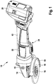
- the handheld power tool designated as a whole by 10 according to FIG Fig. 1 has an elongated housing 12 on which the handheld power tool 10 can be grasped with one hand.
- a motor is accommodated in the front area of the housing 12 and is only indicated here by the number 22.
- a gear head 14 is provided, on each of which a receptacle 15 is provided for attaching a stick handle.
- a tool spindle protrudes from the gear head 14, which is only indicated by 16 here.
- a tool 18 in the form of a grinding or cutting disc is detachably attached to the tool spindle 16, a protective hood 19 also being provided in a known manner.
- an accumulator 20 is detachably attached.
- a switching device designated as a whole by 24, is provided with which actuation of the motor 22 is controlled.
- the hand power tool is typically held with one hand on a handle screwed into the receptacle 15 on the right or left side and with the other hand by grasping the rear end of the housing so that the switching device 24 can be actuated.
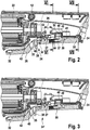
- the switching device 24 has according to Fig. 2 a switch lever 28 which is mounted at a first end 30 on the housing 12 by means of a pivot axis 34.
- the switch lever 28 can be pivoted about the pivot axis 34 and is pretensioned outwardly into its non-activated position by means of a spring 52, so that its second end 32 according to FIG Fig. 2 in the non-activated position protrudes to the outside.
- a locking device designated as a whole by 36, is received within the switch lever 28.
- the locking device 36 comprises a slide 37, which is located on the inside of the switch lever 28 between an in Fig. 2 shown blocking position and a release position is displaceable, in which the slide 37 is displaced forward in the direction of the gear head 14.
- the slide 37 At its front end facing the gear head 14, the slide 37 has an actuating element 38 in the form of a rounded button, which is approximately triangular in cross section and protrudes outward through a recess 35 in the switch lever 28.
- the slide 37 is in its blocking position according to FIG Fig. 2 biased, so that the slide 37 is held in its end position in which the slide 37 rests with its second end 39 on the end of a recess 41 within the switch lever 28.
- a blocking element 46 which is designed as a step that protrudes from the slide in the direction of the interior of the housing 12, rests against an associated counter element 48 of the housing 12.
- the switch 26 has a switch plunger 27 which protrudes from the switch 26 in the direction of the switch lever 28. If the switch lever 28 after a corresponding movement of the locking device 36 is pivoted into a release position (as will be described below) with its second end 32 in the direction of the housing 12, the switch plunger 27 is actuated by the underside of the switch lever 28, so that the switch 26, which can be designed as a button, goes into its on position.
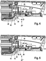
- the switch handle 28 can now be pivoted in the direction of the housing 12, so that the switch plunger 27 is actuated and the position according to FIG Fig. 4
- the motor 22 is thus switched on.
- the handheld power tool 10 could now continue to be held in this position, the motor 22 running as long as the switch lever 28 is in the activated position shown, for example by grasping around with one hand is held.
- the switching device 24 is, however, also designed to allow the switch trigger 24 to be locked in the activated position.
- a locking element 40 in the form of a locking nose is formed, to which a receptacle 42 on the housing 12 is assigned.
- the switch lever 28 can only be tightened further against the action of the tension of the spring 52, so that the locking element 40 is released again from the associated receptacle 42 of the housing 12 and, under the action of the tension of the spring 44, moves backwards again towards the first end 30 of the switch lever moves. If the switch lever 28 is now released, it moves under the action of the spring 52 into its non-activated position, so that the motor 22 is switched off and, if necessary, braking also takes place. In this position, the slide 37 can move into its end position, so that it returns to its blocking position.
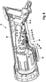
- Fig. 8 It can be seen that on the slide 50, adjacent to the blocking element 46, there is also a projection 50 which protrudes in the direction of the interior of the housing and can be displaced within an associated recess 51 of the housing 12. The projection 50 thus limits the displacement of the slide 37 between the blocking position and the release position.
Description
Die Erfindung betrifft eine Handwerkzeugmaschine mit einem Gehäuse, in dem ein Motor zum Antrieb eines Werkzeugs sowie ein Schalter zum Ein- und Ausschalten des Motors aufgenommen sind, mit einer Schalteinrichtung, die einen Schalterdrücker aufweist, der zwischen einer nicht aktivierten Stellung und einer aktivierten Stellung zur Betätigung des Schalters bewegbar ist, und mit einer Verriegelungseinrichtung, die zwischen einer Blockierstellung und eine Freigabestellung bewegbar ist, wobei der Schalterdrücker nur dann in die aktivierte Stellung bewegbar ist, wenn sich die Verriegelungseinrichtung in der Freigabestellung befindet, und wobei die Verriegelungseinrichtung in der aktivierten Stellung eine Verriegelung des Schalterdrückers in eine Verriegelungsstellung erlaubtThe invention relates to a handheld power tool with a housing in which a motor for driving a tool and a switch for switching the motor on and off are accommodated, with a switching device which has a switch lever that switches between a non-activated position and an activated position Actuation of the switch is movable, and with a locking device which is movable between a blocking position and a release position, the switch lever being only movable into the activated position when the locking device is in the release position, and wherein the locking device is in the activated position a locking of the switch lever in a locking position allowed
Eine derartige Handwerkzeugmaschine ist aus der
Insbesondere bei Winkelschleifern ist es üblich, einen Schalterdrücker im hinteren Bereich des Gehäuses zu verwenden, der mit einer Hand ergriffen werden kann, um den Schalterdrücker zwischen einer nicht aktivierten und einer aktivierten Stellung zur Betätigung eines Schalters zum Ein- und Ausschalten des Motors bewegen zu können. Hierbei ist eine Verriegelungseinrichtung vorgesehen, die eine Betätigung des Schalterdrückers verhindert, solange sich die Verriegelungseinrichtung in einer Blockierstellung befindet. Um eine Bewegung des Schalterdrückers in die aktivierte Stellung zu erlauben, muss zuvor die Verriegelungseinrichtung in eine Freigabestellung bewegt werden.With angle grinders in particular, it is common to use a switch handle in the rear area of the housing that can be gripped with one hand to move the switch handle between an inactive and an activated position to operate a switch to turn the motor on and off . Here, a locking device is provided which prevents actuation of the switch lever as long as the locking device is in a blocking position. In order to allow the switch lever to move into the activated position, the locking device must first be moved into a release position.
Derartige Schalteinrichtungen sollen es verhindern, dass der Winkelschleifer unbeabsichtigt beim Ergreifen anläuft, ferner soll sich der Schalterdrücker beim Loslassen automatisch in seine nicht aktivierte Stellung bewegen, so dass der Motor ausgeschaltet wird und ggf. eine Bremse des Winkelschleifers betätigt wird. Sofern sich der Schalterdrücker in seiner aktivierten Stellung befindet und somit der Motor läuft, kann dieser ferner verriegelt werden, um eine erleichterte Handhabung des Winkelschleifers im längeren Betrieb zu erlauben.Such switching devices are intended to prevent the angle grinder from accidentally starting when it is gripped, and the switch lever should automatically move into its non-activated position when released, so that the motor is switched off and a brake of the angle grinder is activated if necessary. If the switch lever is in its activated position and the motor is running, it can also be locked to allow easier handling of the angle grinder during longer operation.
Die zuvor genannte Handwerkzeugmaschine erfüllt diese Funktionen. In ähnlicher Weise funktioniert auch eine aus der
Aus der
Die
Bei den aus der
Bei dem Schalter aus der
Bei der
Die Schalteinrichtungen bei den bekannten Handwerkzeugmaschinen sind relativ kompliziert aufgebaut und weisen eine relativ komplizierte Handhabung auf.The switching devices in the known hand machine tools are constructed in a relatively complex manner and are relatively complicated to use.
Vor diesem Hintergrund liegt der vorliegenden Erfindung die Aufgabe zugrunde, eine Handwerkzeugmaschine der vorstehend genannten Art derart zu verbessern, dass ein möglichst einfacher Aufbau und eine möglichst einfache Handhabung erreicht werden.Against this background, the present invention is based on the object of improving a handheld power tool of the type mentioned above in such a way that the simplest possible structure and the simplest possible handling are achieved.
Diese Aufgabe wird bei einer Handwerkzeugmaschine der eingangs genannten Art erfindungsgemäß dadurch gelöst, dass die Verriegelungseinrichtung einen Schieber aufweist, der auf der Innenseite des Schalterdrücker zwischen der Blockierstellung und der Freigabestellung verschiebbar aufgenommen ist, dass am Schieber ein Blockierelement vorgesehen ist, das mit einem Gegenelement am Gehäuse zusammenwirkt, um in der Blockierstellung eine Bewegung des Schalterdrückers in die aktivierte Stellung zu blockieren und um bei Verschiebung des Schiebers in die Freigabestellung eine Bewegung des Schalterdrückers in die aktivierte Stellung zu erlauben, und dass am Schieber ein Verriegelungselement vorgesehen ist, das mit einer Aufnahme am Gehäuse zusammenwirkt, um in der aktivierten Stellung eine Verriegelung des Schalterdrückers in die Verriegelungsstellung zu erlauben.This object is achieved according to the invention in a hand machine tool of the type mentioned at the outset in that the locking device has a slide which is slidably received on the inside of the switch lever between the blocking position and the release position Housing cooperates in order to block a movement of the switch handle in the activated position in the blocking position and to move the switch handle into the release position when the slide is moved into the release position To allow activated position, and that a locking element is provided on the slide, which interacts with a receptacle on the housing to allow locking of the switch lever in the locking position in the activated position.
Die Aufgabe der Erfindung wird auf diese Weise gelöst.The object of the invention is achieved in this way.
Während im Stand der Technik die mit dem Schalterdrücker zusammenwirkende Verriegelungseinrichtung einen gegen eine Federspannung verschwenkbaren Schaltknopf aufweist, mit Hilfe dessen die Blockierfunktion in der nicht aktivierten Stellung des Schalterdrückers gewährleistet wird und bei Betätigung dessen der Schalterdrücker in seine aktivierte Stellung bewegt werden kann, ist erfindungsgemäß eine Verriegelungseinrichtung mit einem Schieber am Schalterdrücker vorgesehen, der die Blockier- bzw. Freigabefunktion gewährleistet. Ferner ist mittels des Schiebers in der aktivierten Stellung eine Bewegung des Schalterdrückers in die Verriegelungsstellung ermöglicht, um eine Verriegelung des Schalterdrückers zu gewährleisten.While in the prior art the locking device cooperating with the switch lever has a switch button which can be pivoted against a spring tension, with the aid of which the blocking function is ensured in the non-activated position of the switch lever and when the switch lever is actuated, the switch lever can be moved into its activated position Locking device provided with a slide on the switch handle, which ensures the blocking or release function. Furthermore, by means of the slide in the activated position, a movement of the switch lever into the locking position is made possible in order to ensure locking of the switch lever.
Auf diese Weise ergeben sich ein besonders einfacher und robuster Aufbau und eine leichte Bedienbarkeit.This results in a particularly simple and robust structure and easy operability.
Gemäß einem weiteren Merkmal der Erfindung ist der Schieber in die Blockierstellung vorgespannt.According to a further feature of the invention, the slide is biased into the blocking position.
Auf diese Weise ist gewährleistet, dass der Schieber in seiner Ausgangsstellung immer in der Blockierstellung ist, so dass der Schalterdrücker nicht ohne Weiteres betätigt werden kann.In this way it is ensured that the slide is always in the blocking position in its starting position, so that the switch lever cannot be easily operated.
Gemäß einem weiteren Merkmal der Erfindung ist der Schalterdrücker an einem Ende verschwenkbar gehalten und durch eine Feder in Richtung auf die nicht aktivierte Stellung vorgespannt.According to a further feature of the invention, the switch lever is held pivotably at one end and is biased by a spring in the direction of the non-activated position.
Dies erlaubt eine einfache Betätigung des Schalterdrückers bei der Aktivierung und im Betrieb.This allows the switch lever to be operated easily during activation and operation.
Gemäß einem weiteren Merkmal der Erfindung ist das Blockierelement als eine vom Schieber hervorstehende Stufe ausgebildet, die in der Blockierstellung an einem zugeordneten Vorsprung des Gehäuses anschlägt.According to a further feature of the invention, the blocking element is designed as a step protruding from the slide, which in the blocking position strikes against an associated projection of the housing.
Auf diese Weise ist eine robuste Blockiermöglichkeit gewährleistet.In this way, a robust blocking option is guaranteed.
Gemäß einem weiteren Merkmal der Erfindung weist der Schieber ein Betätigungselement auf, das durch eine Ausnehmung des Schalterdrückers nach außen hervorsteht.According to a further feature of the invention, the slide has an actuating element which protrudes outward through a recess in the switch lever.
Auf diese Weise ist eine einfache Bewegung des Schiebers zwischen der Blockierstellung und der Freigabestellung ermöglicht.In this way, a simple movement of the slide between the blocking position and the release position is made possible.
Das Betätigungselement ist gemäß einem weiteren Merkmal der Erfindung als Knopf ausgebildet, der zur Verschiebung des Schiebers zwischen der Blockierstellung und der Freigabestellung mittels eines Fingers eines Benutzers ausgebildet ist.According to a further feature of the invention, the actuating element is designed as a button which is designed to move the slide between the blocking position and the release position by means of a user's finger.
Dies erlaubt eine sehr einfache Bedienung.This allows a very simple operation.
Gemäß einem weiteren Merkmal der Erfindung ist der Schieber mittels einer Feder in Richtung auf die Blockierstellung vorgespannt und das Verriegelungselement entgegen der Wirkung der Federspannung an der Aufnahme in die Verriegelungsstellung einrastbar.According to a further feature of the invention, the slide and the locking element are prestressed in the direction of the blocking position by means of a spring can be latched into the locking position against the action of the spring tension on the receptacle.
Auf diese Weise ist eine einfache Verriegelung des Schalterdrückers in der aktivierten Stellung ermöglicht.In this way, a simple locking of the switch lever in the activated position is made possible.
Gemäß einer Weiterbildung dieser Ausführung erlaubt die Schalteinrichtung in der Verriegelungsstellung des Schalterdrückers eine weitere Verschwenkung entgegen der Wirkung der Vorspannung der Feder in eine Entriegelungsposition, in der das Verriegelungselement von der Aufnahme freigegeben wird und durch die Feder in Richtung auf die Blockierstellung bewegbar ist.According to a further development of this embodiment, the switching device in the locking position of the switch lever allows further pivoting against the action of the bias of the spring into an unlocking position in which the locking element is released from the receptacle and can be moved by the spring in the direction of the blocking position.
Dies ist ein weiteres Sicherheitsmerkmal, da beim normalen Arbeiten mit der Maschine in der verriegelten Stellung des Schalterdrückers die Maschine an den Griff, an dem der Schalterdrücker aufgenommen ist, gehalten wird. Soll der Motor angehalten werden, so muss der Schalterdrücker lediglich um einen kleinen Betrag entgegen der Wirkung der Federkraft weiter zusammengedrückt werden, wodurch dann das Verriegelungselement unter der Wirkung der Vorspannung der zugeordneten Feder freigegeben wird. Beim anschließenden Loslassen des Schalterdrückers wird somit der Motor angehalten und ggf. eine zugeordnete Bremseinrichtung betätigt.This is a further safety feature, since during normal work with the machine in the locked position of the switch trigger, the machine is held by the handle on which the switch trigger is received. If the motor is to be stopped, the switch lever only needs to be further compressed by a small amount against the action of the spring force, which then releases the locking element under the action of the bias of the associated spring. When the trigger is subsequently released, the motor is stopped and, if necessary, an associated braking device is actuated.
Gemäß einem weiteren Merkmal der Erfindung weist der Schalter einen Schalterstößel auf, der mittels des Schalterdrückers schaltbar ist, wenn der Schalterdrücker in seine aktivierte Stellung bewegt wird.According to a further feature of the invention, the switch has a switch plunger which can be switched by means of the switch lever when the switch lever is moved into its activated position.
Dies erlaubt eine zuverlässige Schaltung des Schalters.This allows the switch to be switched reliably.
Gemäß einer weiteren Ausgestaltung der Erfindung ist der Schieber in einer Ausnehmung des Schalterdrückers von einer dem Gehäuse zugewandten Innenseite einlegbar und mit der Feder vorspannbar und zusammen mit dem Schalterdrücker zwischen zwei Gehäuseteilen montiert.According to a further embodiment of the invention, the slide can be inserted into a recess of the switch lever from an inside facing the housing and can be pretensioned with the spring and mounted together with the switch lever between two housing parts.
Auf diese Weise wird eine einfache Montage der Schalteinrichtung ermöglicht.In this way, simple assembly of the switching device is made possible.
Es versteht sich, dass die vorstehend genannten und die nachstehend noch zu erläuternden Merkmale der Erfindung nicht nur in der jeweils angegebenen Kombination, sondern auch in anderen Kombinationen oder in Alleinstellung verwendbar sind, ohne den Rahmen der Erfindung zu verlassen.It goes without saying that the features of the invention mentioned above and those yet to be explained below can be used not only in the respectively specified combination but also in other combinations or on their own without departing from the scope of the invention.
Weitere Merkmale und Vorteile der Erfindung ergeben sich aus der nachfolgenden Beschreibung eines bevorzugten Ausführungsbeispiels unter Bezugnahme auf die Zeichnung. Es zeigen:
- Fig. 1
- eine perspektivische Ansicht einer erfindungsgemäßen Handwerkzeugmaschine, die beispielhaft als akkubetriebener Winkelschleifer ausgebildet ist;
- Fig. 2
- einen Teil-Längsschnitt der Handwerkzeugmaschine gemäß
Fig. 1 im Bereich der Schalteinrichtung, bei nicht betätigtem Schalterdrücker in der Blockierstellung; - Fig. 3
- den Teil-Längsschnitt der Handwerkzeugmaschine gemäß
Fig. 1 im Bereich der Schalteinrichtung, wobei der Schieber jedoch in die Freigabestellung verschoben wurde; - Fig. 4
- den Teil-Längsschnitt der Handwerkzeugmaschine gemäß
Fig. 1 im Bereich der Schalteinrichtung, wobei der Schalterdrücker jedoch aktiviert wurde; - Fig. 5
- den Teil-Längsschnitt der Handwerkzeugmaschine gemäß
Fig. 1 im Bereich der Schalteinrichtung, wobei der Schalterdrücker aktiviert wurde und der Schieber in die verriegelte Stellung bewegt wurde; - Fig. 6
- einen Querschnitt durch die Handwerkzeugmaschine gemäß
Fig. 4 längs der Linie VI-VI; - Fig. 7
- einen Querschnitt durch die Handwerkzeugmaschine gemäß
Fig. 4 längs der Linie VII-VII; - Fig. 8
- eine perspektivische Ansicht eines Gehäuseteils von innen mit montierter Schalteinrichtung und
- Fig. 9
- den Schalterdrücker mit montierter Verriegelungseinrichtung in perspektivischer Darstellung.
- Fig. 1
- a perspective view of a hand power tool according to the invention, which is exemplified as a battery-operated angle grinder;
- Fig. 2
- a partial longitudinal section of the hand power tool according to
Fig. 1 in the area of the switching device, with the switch lever not actuated in the blocking position; - Fig. 3
- the partial longitudinal section of the hand tool according to
Fig. 1 in the area of the switching device, but the slide has been moved into the release position; - Fig. 4
- the partial longitudinal section of the hand tool according to
Fig. 1 in the area of the switching device, but the switch lever has been activated; - Fig. 5
- the partial longitudinal section of the hand tool according to
Fig. 1 in the area of the switching device, the switch lever being activated and the slide being moved into the locked position; - Fig. 6
- a cross section through the hand tool according to
Fig. 4 along the line VI-VI; - Fig. 7
- a cross section through the hand tool according to
Fig. 4 along the line VII-VII; - Fig. 8
- a perspective view of a housing part from the inside with mounted switching device and
- Fig. 9
- the switch handle with the locking device mounted in a perspective view.
Die insgesamt mit 10 bezeichnete Handwerkzeugmaschine gemäß
Am rückwärtigen Ende des Gehäuses 12 ist ein Akkumulator 20 lösbar befestigt. An der Unterseite des Gehäuses 12 ist eine insgesamt mit 24 bezeichnete Schalteinrichtung vorgesehen, mit der eine Betätigung des Motors 22 gesteuert wird.At the rear end of the
Im Betrieb wird die Handwerkzeugmaschine typischerweise mit einer Hand an einem in die Aufnahme 15 auf der rechten oder linken Seite eingeschraubten Stielhandgriff gehalten und mit der anderen Hand durch Umgreifen des Gehäuses an seinem hinteren Ende, so dass die Schalteinrichtung 24 betätigt werden kann.In operation, the hand power tool is typically held with one hand on a handle screwed into the
Der nähere Aufbau und die Funktion der Schalteinrichtung 24 werden im Folgenden anhand der
Die Schalteinrichtung 24 weist gemäß
Innerhalb des Schalterdrückers 28 ist eine insgesamt mit 36 bezeichnete Verriegelungseinrichtung aufgenommen. Die Verriegelungseinrichtung 36 umfasst einen Schieber 37, der auf der Innenseite des Schalterdrückers 28 zwischen einer in
In dieser Stellung steht ein Blockierelement 46, das als eine Stufe ausgebildet ist, die vom Schieber in Richtung auf das Innere des Gehäuses 12 hervorsteht, an einem zugeordneten Gegenelement 48 des Gehäuses 12 an. Somit ist in dieser Blockierstellung eine Bewegung des Schalterdrückers 28 durch eine Verschwenkung verhindert.In this position, a blocking
Innerhalb des Gehäuses 12 ist ein Schalter 26 aufgenommen, der zum Ein- und Ausschalten des Motors 22 ausgebildet ist. Der Schalter 26 weist einen Schalterstößel 27 auf, der in Richtung zum Schalterdrücker 28 aus dem Schalter 26 hervorsteht. Wird der Schalterdrücker 28 nach einer entsprechenden Bewegung der Verriegelungseinrichtung 36 in eine Freigabestellung (wie nachfolgend noch beschrieben wird) mit seinem zweiten Ende 32 in Richtung auf das Gehäuse 12 verschwenkt, so wird der Schalterstößel 27 durch die Unterseite des Schalterdrückers 28 betätigt, so dass der Schalter 26, der als Taster ausgebildet sein kann, in seine Einschaltstellung übergeht.A
Wird der Schieber 37 durch Betätigung mittels eines Fingers am Betätigungselement 38 nach vorn in Richtung zum Getriebekopf 14 entgegen der Wirkung der Federkraft verschoben, so wird das Blockierelement 46 von seinem Gegenelement 48 freigegeben, so dass die insgesamt mit 24' bezeichnete Position der Schalteinrichtung gemäß
In dieser Position kann der Schalterdrücker 28 nunmehr in Richtung auf das Gehäuse 12 verschwenkt werden, so dass der Schalterstößel 27 betätigt wird und sich die Position gemäß
Die Schalteinrichtung 24 ist ferner jedoch auch dazu ausgebildet, eine Verriegelung des Schalterdrückers 24 in der aktivierten Stellung zu erlauben. Am vorderen Ende des Schiebers 37 ist ein Verriegelungselement 40 in Form einer Verriegelungsnase ausgebildet, der eine Aufnahme 42 am Gehäuse 12 zugeordnet ist.The switching
Wird der Schieber 37 ausgehend von der Stellung gemäß
Soll der Motor 22 angehalten werden, so muss ausgehend von der Position gemäß
Die Schnitte gemäß der
Aus
Zur Montage der Verriegelungseinrichtung 36 am Schalterdrücker 28 wird der Schieber 37 gemäß
Claims (10)
- Handheld machine tool with a housing (12), in which a motor (22) for driving a tool (18), as well as a switch (26) for turning the motor (22) on and off, are accommodated, with a switching device (24), which has a pushbutton switch (28), which can be moved between a non-activated position and an activated position for operation of the switch (26), and with a locking device (36), which can be moved between a blocking position and a release position, wherein the pushbutton switch (28) can only be moved in the activated position when the locking device (36) is in the release position, and wherein the locking device (36) in the activated position allows the pushbutton switch (28) to be locked in a locking position, characterised in that the locking device (36) has a slider (37), which is accommodated on the inside of the pushbutton switch (28) and is movable between the blocking position and the release position, in that a blocking element (46) is provided on the slider (37), which engages with a counter-element (48) on the housing (12), in order to block a movement of the pushbutton switch (28) into the activated position in the blocking position and in order to allow a movement of the pushbutton switch (28) into the activated position when the slider (37) is moved into the release position, and in that a locking element (40) is provided on the slider (37), which engages with a fixture (42) on the housing (12), in order to allow the pushbutton switch (28) to be locked in the locking position in the activated position.
- Handheld machine tool according to claim 1, characterised in that the slider (37) is pre-tensioned in the blocking position.
- Handheld machine tool according to claim 1 or 2, characterised in that the pushbutton switch (28) is held pivotably at one end (30) and is pre-tensioned in the direction of the non-activated position by a spring (52).
- Handheld machine tool according to any of the preceding claims, characterised in that the blocking element (46) is designed as a step protruding from the slider (37), which attaches to an associated projection (48) of the housing (12) in the blocking position.
- Handheld machine tool according to any of the preceding claims, characterised in that the slider (37) has an actuating element (38), which projects outwards through a recess (35) in the pushbutton switch (28).
- Handheld machine tool according to claim 5, characterised in that the actuating element (38) is designed as a button, which is designed to move the slider (37) between the blocking position and the release position when operated by a user's finger.
- Handheld machine tool according to any of the preceding claims, characterised in that the slider (37) is pre-tensioned in the direction of the blocking position by means of a spring (44) and in that, in the activated position, the locking element (40) can be engaged with the fixture (42) counter to the effect of the spring tension into the locking position.
- Handheld machine tool according to claim 7, characterised in that, with the pushbutton switch (28) in the locking position, the switching device (24) permits further pivoting counter to the effect of the spring (52) tension into a release position, in which the locking element (40) is released from the fixture (42) and can be moved in the direction of the blocking position by the spring (44).
- Handheld machine tool according to any of the preceding claims, characterised in that the switch (26) has a switch plunger (27), which can be switched by means of the pushbutton switch (28), when the pushbutton switch (28) is moved into its activated position.
- Handheld machine tool according to any of the preceding claims, characterised in that the slider (27) can be inserted into a recess in the pushbutton switch (28) from an inner side facing the housing (12) and can be pre-tensioned by means of the spring (44) and is mounted, together with the pushbutton switch (28), between two housing parts (56).
Applications Claiming Priority (1)
| Application Number | Priority Date | Filing Date | Title |
|---|---|---|---|
| DE102016125435.5A DE102016125435A1 (en) | 2016-12-22 | 2016-12-22 | Hand tool |
Publications (2)
| Publication Number | Publication Date |
|---|---|
| EP3338960A1 EP3338960A1 (en) | 2018-06-27 |
| EP3338960B1 true EP3338960B1 (en) | 2020-10-21 |
Family
ID=60569680
Family Applications (1)
| Application Number | Title | Priority Date | Filing Date |
|---|---|---|---|
| EP17204688.0A Active EP3338960B1 (en) | 2016-12-22 | 2017-11-30 | Handheld machine tool |
Country Status (4)
| Country | Link |
|---|---|
| US (1) | US10614977B2 (en) |
| EP (1) | EP3338960B1 (en) |
| DE (1) | DE102016125435A1 (en) |
| ES (1) | ES2833901T3 (en) |
Families Citing this family (5)
| Publication number | Priority date | Publication date | Assignee | Title |
|---|---|---|---|---|
| EP3503145B1 (en) | 2017-12-22 | 2023-04-19 | Defond Electech Co., Ltd | A locking system for use with a trigger assembly of an electrical device |
| JP7147871B2 (en) * | 2018-11-30 | 2022-10-05 | 工機ホールディングス株式会社 | work machine |
| DE102019120363B4 (en) * | 2019-04-26 | 2020-11-12 | Defond Components Limited | AN IMPROVED EXTRACTOR WITH A PROTECTIVE COVER |
| DE102019216863A1 (en) * | 2019-10-31 | 2021-05-06 | Robert Bosch Gmbh | Hand machine tool |
| DE102019216865A1 (en) * | 2019-10-31 | 2021-05-06 | Robert Bosch Gmbh | Hand machine tool |
Family Cites Families (49)
| Publication number | Priority date | Publication date | Assignee | Title |
|---|---|---|---|---|
| US2346778A (en) * | 1942-10-16 | 1944-04-18 | Independent Pneumatic Tool Co | Portable hand held electric tool |
| US2636136A (en) * | 1950-03-31 | 1953-04-21 | Wolf Electric Tools Ltd | Electric motor |
| US3746813A (en) * | 1972-01-14 | 1973-07-17 | Cutler Hammer Inc | Lock-off switch |
| US4016941A (en) * | 1973-03-08 | 1977-04-12 | Sanders William H | Hand-size fluid-powered tool reciprocator |
| US3847233A (en) * | 1973-06-29 | 1974-11-12 | Black & Decker Mfg Co | Trigger mechanism for hand-operated power device providing automatic lock-off and manual lock-on operation |
| US4296290A (en) * | 1980-01-16 | 1981-10-20 | The Singer Company | Safety lock-on motor control |
| CH668445A5 (en) * | 1985-02-07 | 1988-12-30 | Gegauf Fritz Ag | WINDING DEVICE FOR SEWING MACHINE. |
| DE3638952A1 (en) * | 1986-11-14 | 1988-05-26 | Marquardt Gmbh | Electrical switch |
| US4986369A (en) * | 1988-07-11 | 1991-01-22 | Makita Electric Works, Ltd. | Torque adjusting mechanism for power driven rotary tools |
| DE19546328B4 (en) * | 1995-12-12 | 2007-12-13 | Robert Bosch Gmbh | Hand tool machine with a rotatable handle |
| JP2977076B2 (en) * | 1996-03-01 | 1999-11-10 | リョービ株式会社 | Power tool switch mechanism |
| JPH11277462A (en) * | 1998-03-27 | 1999-10-12 | Makita Corp | Switch mechanism for power tool |
| DE102004043823A1 (en) * | 2004-09-10 | 2006-03-16 | Robert Bosch Gmbh | Device for locking a power tool with a battery pack |
| TWI266679B (en) * | 2005-06-29 | 2006-11-21 | Basso Ind Corp | Improved mechanism of switching position for user by right or left hand about CW-CCW valve in a pneumatic tool |
| US7802633B2 (en) * | 2006-09-18 | 2010-09-28 | Sp Air Kabushiki Kaisha | Reversible valve assembly for a pneumatic tool |
| JP5073380B2 (en) * | 2007-06-28 | 2012-11-14 | 株式会社マキタ | Electric driving tool |
| JP4507211B2 (en) * | 2007-09-03 | 2010-07-21 | 日立工機株式会社 | Driving machine |
| US20090108046A1 (en) * | 2007-10-24 | 2009-04-30 | Chi-Sheng Huang | Trigger Switch Mechanism for Nail Gun |
| CN101585182B (en) * | 2008-05-23 | 2011-08-31 | 台州市大江实业有限公司 | Nailing gun firing safety device and nailing gun installed with same |
| US8800835B2 (en) * | 2008-07-17 | 2014-08-12 | Stanley Fastening Systems, Lp | Fastener driving device with mode selector and trigger interlock |
| TW201008717A (en) * | 2008-08-18 | 2010-03-01 | Basso Ind Corp | LPG-powered nail gun with safe firing mechanism |
| JP5255959B2 (en) * | 2008-09-03 | 2013-08-07 | 株式会社マキタ | Work tools |
| US20110308920A1 (en) * | 2008-12-17 | 2011-12-22 | Robert Bosch Gmbh | Lock-On Switch System for Hand Drill and Hand Drill having the Same |
| US8198560B2 (en) | 2009-01-09 | 2012-06-12 | Makita Corporation | Switch devices for power tools |
| US20100301091A1 (en) * | 2009-06-01 | 2010-12-02 | Chia-Sheng Liang | Linkage Mechanism between Trigger Valve and Control Valve in Pneumatic Nail Guns |
| US8746526B2 (en) * | 2009-09-15 | 2014-06-10 | Robert Bosch Gmbh | Fastener driver with blank fire lockout |
| US8336748B2 (en) * | 2009-09-15 | 2012-12-25 | Robert Bosch Gmbh | Fastener driver with driver assembly blocking member |
| TW201117930A (en) * | 2009-11-19 | 2011-06-01 | De Poan Pneumatic Corp | Driving device for resetting a nail hitting bar the a pneumatic nail gun |
| US8631986B2 (en) * | 2009-12-04 | 2014-01-21 | Robert Bosch Gmbh | Fastener driver with an operating switch |
| JP5360692B2 (en) * | 2010-03-31 | 2013-12-04 | 日立工機株式会社 | Combustion type driving machine |
| TWI392566B (en) * | 2010-08-10 | 2013-04-11 | Basso Ind Corp | Vessel nail gun against the air firing device |
| US9259832B2 (en) * | 2010-08-25 | 2016-02-16 | Makita Corporation | Handheld electrical power tools |
| TWM403405U (en) * | 2010-11-03 | 2011-05-11 | Basso Ind Corp | Control structure of electrical nailing gun |
| DE102010063962A1 (en) * | 2010-12-22 | 2012-06-28 | Robert Bosch Gmbh | Lockable electrical switch |
| DE202011108753U1 (en) * | 2011-12-06 | 2012-01-24 | Gardena Manufacturing Gmbh | Hand-held device with a control lever |
| US8872049B2 (en) * | 2012-04-18 | 2014-10-28 | Milwaukee Electric Tool Corporation | Trigger lock-on lock-off mechanism |
| CA2840260C (en) * | 2012-08-28 | 2016-11-01 | Miao Zhang | Working tool |
| DE102012223931A1 (en) * | 2012-12-20 | 2014-06-26 | Robert Bosch Gmbh | Tool i.e. hand-held power tool, e.g. rechargeable battery nut runner, has housing with two housing half-casings, which are combined together to form guide way for housing and form captured locking switch between half-casings |
| DE102012025309A1 (en) * | 2012-12-22 | 2014-06-26 | Andreas Stihl Ag & Co. Kg | Hand-guided implement with a drive motor for driving at least one tool and method for its operation |
| US20140290973A1 (en) * | 2013-03-27 | 2014-10-02 | Johnson Lin | Pneumatic tool having a rotatable output shaft |
| DE102013212907A1 (en) * | 2013-07-02 | 2015-01-08 | Robert Bosch Gmbh | Electric machine tool with a slide switch |
| TWM475341U (en) | 2013-10-04 | 2014-04-01 | Tranmax Machinery Co Ltd | Switch component for use in power tool |
| US10014128B2 (en) * | 2013-12-17 | 2018-07-03 | Robert Bosch Tool Corporation | Portable power tool with trigger switch, trigger release and lock-on mechanism combination |
| JP6277042B2 (en) * | 2014-04-01 | 2018-02-07 | 株式会社マキタ | Electric tool |
| US10418795B2 (en) * | 2016-06-08 | 2019-09-17 | Milwaukee Electric Tool Corporation | Tool having an inclined handle |
| US10150211B2 (en) * | 2016-07-22 | 2018-12-11 | Ming-Ta Cheng | Steering-switching and hands-changing assembly for a pneumatic tool |
| US20180093335A1 (en) * | 2016-10-04 | 2018-04-05 | Tti (Macao Commercial Offshore) Limited | Trigger lock for a miter saw |
| US10207380B2 (en) * | 2016-12-09 | 2019-02-19 | Black & Decker Inc. | Power tool and light unit |
| US10818450B2 (en) * | 2017-06-14 | 2020-10-27 | Black & Decker Inc. | Paddle switch |
-
2016
- 2016-12-22 DE DE102016125435.5A patent/DE102016125435A1/en not_active Withdrawn
-
2017
- 2017-11-30 EP EP17204688.0A patent/EP3338960B1/en active Active
- 2017-11-30 ES ES17204688T patent/ES2833901T3/en active Active
- 2017-12-14 US US15/841,374 patent/US10614977B2/en active Active
Non-Patent Citations (1)
| Title |
|---|
| None * |
Also Published As
| Publication number | Publication date |
|---|---|
| US20180182577A1 (en) | 2018-06-28 |
| EP3338960A1 (en) | 2018-06-27 |
| ES2833901T3 (en) | 2021-06-16 |
| US10614977B2 (en) | 2020-04-07 |
| DE102016125435A1 (en) | 2018-06-28 |
Similar Documents
| Publication | Publication Date | Title |
|---|---|---|
| EP3338960B1 (en) | Handheld machine tool | |
| EP3030385B1 (en) | Knife | |
| DE102005049411B3 (en) | Knife, has operation lug, held outside of blade bolt at base plate, where inner surfaces hold bolt in its closed position close to plate and release bolt for opening bolt and taking out knife blade | |
| DE202012103341U1 (en) | Motor vehicle with interchangeable blade | |
| EP2942164A1 (en) | Knife with automatic blade return | |
| DE102007011168B4 (en) | Circular saw | |
| EP3041646A1 (en) | Knife | |
| DE202011108753U1 (en) | Hand-held device with a control lever | |
| EP3184706B1 (en) | Holding device with a holding slider sliding along a holding bar | |
| EP2140466B1 (en) | Electric switch | |
| EP2487446A2 (en) | Action for repeating rifle | |
| DE102012112882B4 (en) | Lancing device for obtaining body fluid samples | |
| EP3065978A1 (en) | Steering column lock for a steering column for a motor vehicle | |
| DE202008002672U1 (en) | Electric hand tool | |
| DE102006060880A1 (en) | Electric hand-held tool has locking arrangement arranged so that it can be operated by user with hand holding tool in handle region without removing it from handle region | |
| EP2088943B1 (en) | Surgical obturator | |
| EP3342536B1 (en) | Electric hand-held machine tool | |
| EP2904977A1 (en) | Surgical instrument and handle for same | |
| DE102008007090B3 (en) | Craft knife designed for safe operation, has blade carrier swinging about axis fixed relative to casing, with spring bias for safe retraction after cutting | |
| DE1038944B (en) | Device for actuating a latch of a motor vehicle door lock with a push button | |
| DE102017100089B4 (en) | triggering device | |
| DE19724567A1 (en) | Rotary switch e.g. for circular saw | |
| DE20317950U1 (en) | A method for preventing the operation of an electric hand tool has a double locking system to prevent operation of the motor and also the rotation of the shaft | |
| DE102019003733A1 (en) | Hand machine tool | |
| DE202014103845U1 (en) | Adjustable wrench |
Legal Events
| Date | Code | Title | Description |
|---|---|---|---|
| PUAI | Public reference made under article 153(3) epc to a published international application that has entered the european phase |
Free format text: ORIGINAL CODE: 0009012 |
|
| STAA | Information on the status of an ep patent application or granted ep patent |
Free format text: STATUS: THE APPLICATION HAS BEEN PUBLISHED |
|
| AK | Designated contracting states |
Kind code of ref document: A1 Designated state(s): AL AT BE BG CH CY CZ DE DK EE ES FI FR GB GR HR HU IE IS IT LI LT LU LV MC MK MT NL NO PL PT RO RS SE SI SK SM TR |
|
| AX | Request for extension of the european patent |
Extension state: BA ME |
|
| STAA | Information on the status of an ep patent application or granted ep patent |
Free format text: STATUS: REQUEST FOR EXAMINATION WAS MADE |
|
| 17P | Request for examination filed |
Effective date: 20181210 |
|
| RBV | Designated contracting states (corrected) |
Designated state(s): AL AT BE BG CH CY CZ DE DK EE ES FI FR GB GR HR HU IE IS IT LI LT LU LV MC MK MT NL NO PL PT RO RS SE SI SK SM TR |
|
| GRAP | Despatch of communication of intention to grant a patent |
Free format text: ORIGINAL CODE: EPIDOSNIGR1 |
|
| STAA | Information on the status of an ep patent application or granted ep patent |
Free format text: STATUS: GRANT OF PATENT IS INTENDED |
|
| INTG | Intention to grant announced |
Effective date: 20200724 |
|
| GRAS | Grant fee paid |
Free format text: ORIGINAL CODE: EPIDOSNIGR3 |
|
| GRAA | (expected) grant |
Free format text: ORIGINAL CODE: 0009210 |
|
| STAA | Information on the status of an ep patent application or granted ep patent |
Free format text: STATUS: THE PATENT HAS BEEN GRANTED |
|
| AK | Designated contracting states |
Kind code of ref document: B1 Designated state(s): AL AT BE BG CH CY CZ DE DK EE ES FI FR GB GR HR HU IE IS IT LI LT LU LV MC MK MT NL NO PL PT RO RS SE SI SK SM TR |
|
| REG | Reference to a national code |
Ref country code: GB Ref legal event code: FG4D Free format text: NOT ENGLISH |
|
| REG | Reference to a national code |
Ref country code: CH Ref legal event code: EP |
|
| REG | Reference to a national code |
Ref country code: IE Ref legal event code: FG4D Free format text: LANGUAGE OF EP DOCUMENT: GERMAN |
|
| REG | Reference to a national code |
Ref country code: DE Ref legal event code: R096 Ref document number: 502017007824 Country of ref document: DE |
|
| REG | Reference to a national code |
Ref country code: AT Ref legal event code: REF Ref document number: 1325367 Country of ref document: AT Kind code of ref document: T Effective date: 20201115 |
|
| REG | Reference to a national code |
Ref country code: NL Ref legal event code: MP Effective date: 20201021 |
|
| PG25 | Lapsed in a contracting state [announced via postgrant information from national office to epo] |
Ref country code: NO Free format text: LAPSE BECAUSE OF FAILURE TO SUBMIT A TRANSLATION OF THE DESCRIPTION OR TO PAY THE FEE WITHIN THE PRESCRIBED TIME-LIMIT Effective date: 20210121 Ref country code: RS Free format text: LAPSE BECAUSE OF FAILURE TO SUBMIT A TRANSLATION OF THE DESCRIPTION OR TO PAY THE FEE WITHIN THE PRESCRIBED TIME-LIMIT Effective date: 20201021 Ref country code: PT Free format text: LAPSE BECAUSE OF FAILURE TO SUBMIT A TRANSLATION OF THE DESCRIPTION OR TO PAY THE FEE WITHIN THE PRESCRIBED TIME-LIMIT Effective date: 20210222 Ref country code: GR Free format text: LAPSE BECAUSE OF FAILURE TO SUBMIT A TRANSLATION OF THE DESCRIPTION OR TO PAY THE FEE WITHIN THE PRESCRIBED TIME-LIMIT Effective date: 20210122 Ref country code: FI Free format text: LAPSE BECAUSE OF FAILURE TO SUBMIT A TRANSLATION OF THE DESCRIPTION OR TO PAY THE FEE WITHIN THE PRESCRIBED TIME-LIMIT Effective date: 20201021 |
|
| REG | Reference to a national code |
Ref country code: LT Ref legal event code: MG4D |
|
| PG25 | Lapsed in a contracting state [announced via postgrant information from national office to epo] |
Ref country code: SE Free format text: LAPSE BECAUSE OF FAILURE TO SUBMIT A TRANSLATION OF THE DESCRIPTION OR TO PAY THE FEE WITHIN THE PRESCRIBED TIME-LIMIT Effective date: 20201021 Ref country code: BG Free format text: LAPSE BECAUSE OF FAILURE TO SUBMIT A TRANSLATION OF THE DESCRIPTION OR TO PAY THE FEE WITHIN THE PRESCRIBED TIME-LIMIT Effective date: 20210121 Ref country code: IS Free format text: LAPSE BECAUSE OF FAILURE TO SUBMIT A TRANSLATION OF THE DESCRIPTION OR TO PAY THE FEE WITHIN THE PRESCRIBED TIME-LIMIT Effective date: 20210221 Ref country code: LV Free format text: LAPSE BECAUSE OF FAILURE TO SUBMIT A TRANSLATION OF THE DESCRIPTION OR TO PAY THE FEE WITHIN THE PRESCRIBED TIME-LIMIT Effective date: 20201021 Ref country code: PL Free format text: LAPSE BECAUSE OF FAILURE TO SUBMIT A TRANSLATION OF THE DESCRIPTION OR TO PAY THE FEE WITHIN THE PRESCRIBED TIME-LIMIT Effective date: 20201021 |
|
| REG | Reference to a national code |
Ref country code: ES Ref legal event code: FG2A Ref document number: 2833901 Country of ref document: ES Kind code of ref document: T3 Effective date: 20210616 |
|
| PG25 | Lapsed in a contracting state [announced via postgrant information from national office to epo] |
Ref country code: HR Free format text: LAPSE BECAUSE OF FAILURE TO SUBMIT A TRANSLATION OF THE DESCRIPTION OR TO PAY THE FEE WITHIN THE PRESCRIBED TIME-LIMIT Effective date: 20201021 Ref country code: NL Free format text: LAPSE BECAUSE OF FAILURE TO SUBMIT A TRANSLATION OF THE DESCRIPTION OR TO PAY THE FEE WITHIN THE PRESCRIBED TIME-LIMIT Effective date: 20201021 |
|
| REG | Reference to a national code |
Ref country code: CH Ref legal event code: PL |
|
| REG | Reference to a national code |
Ref country code: DE Ref legal event code: R097 Ref document number: 502017007824 Country of ref document: DE |
|
| PG25 | Lapsed in a contracting state [announced via postgrant information from national office to epo] |
Ref country code: SK Free format text: LAPSE BECAUSE OF FAILURE TO SUBMIT A TRANSLATION OF THE DESCRIPTION OR TO PAY THE FEE WITHIN THE PRESCRIBED TIME-LIMIT Effective date: 20201021 Ref country code: RO Free format text: LAPSE BECAUSE OF FAILURE TO SUBMIT A TRANSLATION OF THE DESCRIPTION OR TO PAY THE FEE WITHIN THE PRESCRIBED TIME-LIMIT Effective date: 20201021 Ref country code: SM Free format text: LAPSE BECAUSE OF FAILURE TO SUBMIT A TRANSLATION OF THE DESCRIPTION OR TO PAY THE FEE WITHIN THE PRESCRIBED TIME-LIMIT Effective date: 20201021 Ref country code: EE Free format text: LAPSE BECAUSE OF FAILURE TO SUBMIT A TRANSLATION OF THE DESCRIPTION OR TO PAY THE FEE WITHIN THE PRESCRIBED TIME-LIMIT Effective date: 20201021 Ref country code: CZ Free format text: LAPSE BECAUSE OF FAILURE TO SUBMIT A TRANSLATION OF THE DESCRIPTION OR TO PAY THE FEE WITHIN THE PRESCRIBED TIME-LIMIT Effective date: 20201021 Ref country code: MC Free format text: LAPSE BECAUSE OF FAILURE TO SUBMIT A TRANSLATION OF THE DESCRIPTION OR TO PAY THE FEE WITHIN THE PRESCRIBED TIME-LIMIT Effective date: 20201021 Ref country code: LT Free format text: LAPSE BECAUSE OF FAILURE TO SUBMIT A TRANSLATION OF THE DESCRIPTION OR TO PAY THE FEE WITHIN THE PRESCRIBED TIME-LIMIT Effective date: 20201021 Ref country code: LU Free format text: LAPSE BECAUSE OF NON-PAYMENT OF DUE FEES Effective date: 20201130 |
|
| PLBE | No opposition filed within time limit |
Free format text: ORIGINAL CODE: 0009261 |
|
| STAA | Information on the status of an ep patent application or granted ep patent |
Free format text: STATUS: NO OPPOSITION FILED WITHIN TIME LIMIT |
|
| PG25 | Lapsed in a contracting state [announced via postgrant information from national office to epo] |
Ref country code: CH Free format text: LAPSE BECAUSE OF NON-PAYMENT OF DUE FEES Effective date: 20201130 Ref country code: LI Free format text: LAPSE BECAUSE OF NON-PAYMENT OF DUE FEES Effective date: 20201130 Ref country code: DK Free format text: LAPSE BECAUSE OF FAILURE TO SUBMIT A TRANSLATION OF THE DESCRIPTION OR TO PAY THE FEE WITHIN THE PRESCRIBED TIME-LIMIT Effective date: 20201021 |
|
| REG | Reference to a national code |
Ref country code: IE Ref legal event code: MM4A |
|
| 26N | No opposition filed |
Effective date: 20210722 |
|
| PG25 | Lapsed in a contracting state [announced via postgrant information from national office to epo] |
Ref country code: AL Free format text: LAPSE BECAUSE OF FAILURE TO SUBMIT A TRANSLATION OF THE DESCRIPTION OR TO PAY THE FEE WITHIN THE PRESCRIBED TIME-LIMIT Effective date: 20201021 Ref country code: IE Free format text: LAPSE BECAUSE OF NON-PAYMENT OF DUE FEES Effective date: 20201130 |
|
| PG25 | Lapsed in a contracting state [announced via postgrant information from national office to epo] |
Ref country code: SI Free format text: LAPSE BECAUSE OF FAILURE TO SUBMIT A TRANSLATION OF THE DESCRIPTION OR TO PAY THE FEE WITHIN THE PRESCRIBED TIME-LIMIT Effective date: 20201021 |
|
| PG25 | Lapsed in a contracting state [announced via postgrant information from national office to epo] |
Ref country code: IS Free format text: LAPSE BECAUSE OF FAILURE TO SUBMIT A TRANSLATION OF THE DESCRIPTION OR TO PAY THE FEE WITHIN THE PRESCRIBED TIME-LIMIT Effective date: 20210221 Ref country code: TR Free format text: LAPSE BECAUSE OF FAILURE TO SUBMIT A TRANSLATION OF THE DESCRIPTION OR TO PAY THE FEE WITHIN THE PRESCRIBED TIME-LIMIT Effective date: 20201021 Ref country code: MT Free format text: LAPSE BECAUSE OF FAILURE TO SUBMIT A TRANSLATION OF THE DESCRIPTION OR TO PAY THE FEE WITHIN THE PRESCRIBED TIME-LIMIT Effective date: 20201021 Ref country code: CY Free format text: LAPSE BECAUSE OF FAILURE TO SUBMIT A TRANSLATION OF THE DESCRIPTION OR TO PAY THE FEE WITHIN THE PRESCRIBED TIME-LIMIT Effective date: 20201021 |
|
| PG25 | Lapsed in a contracting state [announced via postgrant information from national office to epo] |
Ref country code: MK Free format text: LAPSE BECAUSE OF FAILURE TO SUBMIT A TRANSLATION OF THE DESCRIPTION OR TO PAY THE FEE WITHIN THE PRESCRIBED TIME-LIMIT Effective date: 20201021 |
|
| PGFP | Annual fee paid to national office [announced via postgrant information from national office to epo] |
Ref country code: BE Payment date: 20221118 Year of fee payment: 6 |
|
| REG | Reference to a national code |
Ref country code: AT Ref legal event code: MM01 Ref document number: 1325367 Country of ref document: AT Kind code of ref document: T Effective date: 20221130 |
|
| PGFP | Annual fee paid to national office [announced via postgrant information from national office to epo] |
Ref country code: GB Payment date: 20231123 Year of fee payment: 7 |
|
| PGFP | Annual fee paid to national office [announced via postgrant information from national office to epo] |
Ref country code: ES Payment date: 20231215 Year of fee payment: 7 |
|
| PG25 | Lapsed in a contracting state [announced via postgrant information from national office to epo] |
Ref country code: AT Free format text: LAPSE BECAUSE OF NON-PAYMENT OF DUE FEES Effective date: 20221130 |
|
| PGFP | Annual fee paid to national office [announced via postgrant information from national office to epo] |
Ref country code: IT Payment date: 20231130 Year of fee payment: 7 Ref country code: FR Payment date: 20231122 Year of fee payment: 7 Ref country code: DE Payment date: 20231120 Year of fee payment: 7 |
|
| PGFP | Annual fee paid to national office [announced via postgrant information from national office to epo] |
Ref country code: BE Payment date: 20231121 Year of fee payment: 7 |