EP3338942B1 - Dispositif de guidage adapte pour se positionner sur une surface a double rayon de courbure - Google Patents
Dispositif de guidage adapte pour se positionner sur une surface a double rayon de courbure Download PDFInfo
- Publication number
- EP3338942B1 EP3338942B1 EP17205371.2A EP17205371A EP3338942B1 EP 3338942 B1 EP3338942 B1 EP 3338942B1 EP 17205371 A EP17205371 A EP 17205371A EP 3338942 B1 EP3338942 B1 EP 3338942B1
- Authority
- EP
- European Patent Office
- Prior art keywords
- rail
- runner
- head
- cross
- face
- Prior art date
- Legal status (The legal status is an assumption and is not a legal conclusion. Google has not performed a legal analysis and makes no representation as to the accuracy of the status listed.)
- Not-in-force
Links
Images
Classifications
-
- B—PERFORMING OPERATIONS; TRANSPORTING
- B64—AIRCRAFT; AVIATION; COSMONAUTICS
- B64F—GROUND OR AIRCRAFT-CARRIER-DECK INSTALLATIONS SPECIALLY ADAPTED FOR USE IN CONNECTION WITH AIRCRAFT; DESIGNING, MANUFACTURING, ASSEMBLING, CLEANING, MAINTAINING OR REPAIRING AIRCRAFT, NOT OTHERWISE PROVIDED FOR; HANDLING, TRANSPORTING, TESTING OR INSPECTING AIRCRAFT COMPONENTS, NOT OTHERWISE PROVIDED FOR
- B64F5/00—Designing, manufacturing, assembling, cleaning, maintaining or repairing aircraft, not otherwise provided for; Handling, transporting, testing or inspecting aircraft components, not otherwise provided for
- B64F5/10—Manufacturing or assembling aircraft, e.g. jigs therefor
-
- B—PERFORMING OPERATIONS; TRANSPORTING
- B25—HAND TOOLS; PORTABLE POWER-DRIVEN TOOLS; MANIPULATORS
- B25H—WORKSHOP EQUIPMENT, e.g. FOR MARKING-OUT WORK; STORAGE MEANS FOR WORKSHOPS
- B25H1/00—Work benches; Portable stands or supports for positioning portable tools or work to be operated on thereby
- B25H1/0021—Stands, supports or guiding devices for positioning portable tools or for securing them to the work
- B25H1/0042—Stands
-
- B—PERFORMING OPERATIONS; TRANSPORTING
- B23—MACHINE TOOLS; METAL-WORKING NOT OTHERWISE PROVIDED FOR
- B23Q—DETAILS, COMPONENTS, OR ACCESSORIES FOR MACHINE TOOLS, e.g. ARRANGEMENTS FOR COPYING OR CONTROLLING; MACHINE TOOLS IN GENERAL CHARACTERISED BY THE CONSTRUCTION OF PARTICULAR DETAILS OR COMPONENTS; COMBINATIONS OR ASSOCIATIONS OF METAL-WORKING MACHINES, NOT DIRECTED TO A PARTICULAR RESULT
- B23Q9/00—Arrangements for supporting or guiding portable metal-working machines or apparatus
- B23Q9/0014—Portable machines provided with or cooperating with guide means supported directly by the workpiece during action
- B23Q9/0042—Portable machines provided with or cooperating with guide means supported directly by the workpiece during action the guide means being fixed only on the workpiece
-
- B—PERFORMING OPERATIONS; TRANSPORTING
- B23—MACHINE TOOLS; METAL-WORKING NOT OTHERWISE PROVIDED FOR
- B23Q—DETAILS, COMPONENTS, OR ACCESSORIES FOR MACHINE TOOLS, e.g. ARRANGEMENTS FOR COPYING OR CONTROLLING; MACHINE TOOLS IN GENERAL CHARACTERISED BY THE CONSTRUCTION OF PARTICULAR DETAILS OR COMPONENTS; COMBINATIONS OR ASSOCIATIONS OF METAL-WORKING MACHINES, NOT DIRECTED TO A PARTICULAR RESULT
- B23Q9/00—Arrangements for supporting or guiding portable metal-working machines or apparatus
- B23Q9/02—Arrangements for supporting or guiding portable metal-working machines or apparatus for securing machines or apparatus to workpieces, or other parts, of particular shape, e.g. to beams of particular cross-section
-
- B—PERFORMING OPERATIONS; TRANSPORTING
- B23—MACHINE TOOLS; METAL-WORKING NOT OTHERWISE PROVIDED FOR
- B23Q—DETAILS, COMPONENTS, OR ACCESSORIES FOR MACHINE TOOLS, e.g. ARRANGEMENTS FOR COPYING OR CONTROLLING; MACHINE TOOLS IN GENERAL CHARACTERISED BY THE CONSTRUCTION OF PARTICULAR DETAILS OR COMPONENTS; COMBINATIONS OR ASSOCIATIONS OF METAL-WORKING MACHINES, NOT DIRECTED TO A PARTICULAR RESULT
- B23Q2210/00—Machine tools incorporating a specific component
- B23Q2210/008—Flexible guiding rails
Definitions
- the present application relates to a guide device adapted to position itself on a surface with a double radius of curvature.
- a guide device is positioned temporarily on the outer surface of the fuselage in order to guide a tool in a working direction.
- a fuselage of an aircraft comprises several sections placed end to end at the level of transverse planes and each having an outer surface.
- the guide device 10 then follows the profile of a surface having a radius of curvature in the first direction.
- non-developable surfaces have a double radius of curvature and in particular have a first radius in a direction parallel to a transverse plane of the aircraft and a second radius of curvature in a second direction perpendicular to a transverse plane of the aircraft. .
- the guide device 10 When the guide device 10 is positioned on a section of the fuselage having a non-developable surface, it follows the shapes of the surface and naturally tends to move away from the working direction that the tool must follow. Thus, a first end of the guide device 10 is arranged close to the working direction then that the second end of the guide device 10 is away from the working direction. For certain sections of the fuselage, the difference between the second end of the guide device 10 and the direction of work that the tool must follow is too great to be compensated for by the dimensions of the tool. In addition, due to this gap, the rail 12 may exhibit a twist which blocks the movement of the tool along the rail and the guide device 10 may interfere with other elements positioned around the fuselage.
- the guide device 10 cannot be positioned parallel to a transverse plane because in this position the entire surface of the suction cups is not in contact with the surface. fuselage 18.
- each suction cup is in contact with the surface of the fuselage 18, the other end 14.2 being separated.
- the document EP2384842 describes a rail for guiding a welding apparatus.
- This rail is connected to a plurality of supports each of them being connected to the rail by a ball joint.
- the pivot axis between the rail and each support is positioned at the level of the ball joint, between the support and the rail, and it is spaced from the surface of the support configured to be pressed against the work surface. This configuration does not allow adaptation to a change in curvature of the work surface.
- the present invention aims to remedy the drawbacks of the prior art.
- the rail can be positioned parallel to the direction of work on an exterior surface of a non-developable fuselage, each pad being pressed over its entire surface on the exterior surface of the fuselage.
- the pivot axis is positioned on a first face of the pad configured to be pressed against a work surface on which the guide device is attached in operation, equidistant from the lateral edges of the pad.
- each shoe / rail connection comprises a first part secured to the rail, a second part secured to the shoe, the first and second parts having shapes which cooperate, configured to form a sliding link in an arc of a circle with a center positioned on the pivot axis.
- each pad coincides with the center of the first face of the pad and each pad remains stationary when the pad is pressed against the work surface.
- the second part comprises a body connected to the shoe which has an oblong hole comprising an upper edge and a lower edge coaxial and the first part comprises a cross member connected to the rail and a head integral with the cross member, said head comprising a upper face configured to be pressed and slid on the upper edge of the oblong hole and a lower face configured to be pressed and slipped on the lower edge of the oblong hole.
- each shoe is connected to the rail by two shoe / rail connections, offset in the direction, the supports connecting the heads to the sleepers being positioned between the bodies of the two shoe / rail connections.
- the figure 3 illustrates a fuselage 20 of an aircraft which comprises several sections 22.1 to 22.4 placed end to end at the level of transverse planes P1, P2, P3 and each having an outer surface 24.1 to 24.4.
- the outer surface 24.1, 24.4 is substantially cylindrical and includes a radius of curvature.
- the outer surface 24.3 and 24.4 is non-developable and has several radii of curvature, in particular two radii of curvature in the case of section 22.3.
- a guide device 26 is positioned on the outer surface 24.3 called the working surface, near the transverse plane P3, parallel to the transverse plane P3.
- the rail 28 is configured to occupy a shaped state in which the support surface 29 of the rail 28 is parallel to the work surface 24.3.
- the rail 28 can be deformed according to a first radius of curvature R1 visible on the figure 4 and according to a second radius of curvature R2, in a plane perpendicular to the direction D, visible on the figure 5 .
- the rail is not further described because it can be identical to the rails of the prior art.
- the rail 28 comprises a vertical mid-plane PMV which is parallel to the direction D, equidistant from the edges 28.1 and 28.2 of the rail 28 and perpendicular to the support surface 29 of the rail 28.
- the shoe 32 comprises side edges 32.1 and 32.2 parallel to the direction D and also positioned equidistant from the vertical mid-plane PMV.
- each pad 32 comprises a sole 36 configured to deform according to the first and second radii of curvature R1 and R2 which comprises a first face 36.1 configured to be pressed against the work surface 24.3 and a second face 36.2 opposite to the first face 36.1 and oriented towards the rail 28, as well as two rigid blocks 38.1 and 38.2 positioned on the second face 36.2 and integral with the sole 36.
- the two rigid blocks 38.1 and 38.2 are offset in the direction D to allow the sole 36 to deform according to the first radius of curvature R1.
- each pad 32 is of the suction cup type.
- the pads can be of the electromagnetic type, the immobilization of the pad relative to the work surface 24.3 not being generated by depression but by magnetization.
- Other technical solutions can be envisaged for immobilizing the pads 32 temporarily relative to the work surface 24.3.
- the guide device comprises at least one control for checking the state of the pads 32.
- each shoe / rail link 34 is configured to allow each shoe 32 to pivot independently of the other shoes 32 relative to the rail 28 about a pivot axis A34 parallel to the direction D and positioned in the vertical mid-plane PMV.
- the rail 28 can be positioned parallel to a transverse plane on a work surface with a double radius of curvature, each shoe 32 being pressed against the entire first face 36.1 against the work surface 24.3.
- the direction D of the rail 28 is parallel to the working direction 31 that the tool 30 must follow.
- Each shoe / rail link 34 comprises a first part 40 integral with the rail 28 and a second part 42 integral with the shoe 32.
- the first part 40 is connected to the second part 42 by an axis of rotation 44 which forms the pivot axis A34.
- the first and second parts 40, 42 have forms which cooperate, configured to form a sliding link 46 in an arc of a circle with a center positioned on the pivot axis A34.
- the pivot axis A34 is positioned on the first face 36.1, equidistant from the lateral edges 32.1 and 32.2 of the pad 32.
- the pivot axis A34 is positioned at an interface between the pad. pad 32 and the work surface 24.3. This positioning combined with the fact that the pivot axis A34 is equidistant from the lateral edges 32.1 and 32.2 of each pad 32 allows the pads 32 to be shaped on the work surface 24.3 without generating a displacement of the center of each pad 32.
- the second part 42 comprises a body 48 in the form of an arc of a circle which has an oblong hole 50 in an arc of a circle with a center of curvature positioned on the pivot axis A34.
- the oblong hole 50 has an upper edge 50S and a lower edge 50I coaxial having the same axis coincident with the pivot axis A34.
- the radius of the arcuate shape of the oblong hole 50 is determined so that the pivot axis A34 is positioned on the first face 36.1, equidistant from the side edges 32.1 and 32.2 of the pad 32.
- the body 48 comprises two ends 48.1 and 48.2 connected to the pad 32 by any appropriate fixing means 52, such as screws or bolts for example, and kept apart from the pad by means of two spacers 54, one at each end 48.1, 48.2.
- the first part 40 comprises a cross member 56 connected to the rail 28 by any appropriate fixing means 58, such as screws or bolts for example, and a head 60 integral with the cross member 56, said head 60 comprising shapes adapted to slide in the oblong hole 50 of the second part 42.
- the head 60 comprises an upper face 60S configured to be pressed against and slid over the upper edge 50S of the oblong hole 50 as well as a lower face 60I configured to be pressed against and slipped onto the lower edge 50I of the oblong hole 50.
- the head 60 has a length less than that of the oblong hole 50 to allow it to slide in the oblong hole 50.
- the head 60 is offset with respect to the cross member 56 towards the pivot axis A34, in a direction radial (perpendicular to the pivot axis A34).
- the head 60 is connected to the cross member 56 by a support 62.
- the cross member 56, the head 60 and the support 62 are one and the same part.
- the cross member 56 comprises a recess 64 at the level of the support 62 to house a guide system 66, such as a rack for example, provided at the level of the rail 28.
- a guide system 66 such as a rack for example
- the cross member 56 comprises, on a first face 68 oriented towards the head 60, at least one cylindrical cutout 70 coaxial with the upper face 60S of the head 60.
- the body 48 comprises an upper face 48S oriented towards the coaxial cross member 56. at the edge 50S of the oblong hole 50.
- the distance between the upper face 48S and the upper edge 50S of the oblong hole 50 is equal to the distance between the upper face 60S of the head 60 and the cutout 70 of the cross member 56.
- each shoe 32 is connected to rail 28 by two shoe / rail connections 34, offset in the direction D, one for each rigid block 38.
- the supports 62 connecting the heads 60 to the sleepers 56 are positioned between the bodies 48 to prevent the heads 60 from coming out of the oblong holes 50.
- the rail 28 can be positioned in a controlled working direction 31. Moreover, thanks to the invention, a technical space is arranged between the rail 28 and the pads 32 for the integration of additional functions necessary for vacuum management systems, electrical supply or the like.
Landscapes
- Engineering & Computer Science (AREA)
- Mechanical Engineering (AREA)
- Manufacturing & Machinery (AREA)
- Transportation (AREA)
- Aviation & Aerospace Engineering (AREA)
- Machine Tool Units (AREA)
- Automatic Assembly (AREA)
- Footwear And Its Accessory, Manufacturing Method And Apparatuses (AREA)
Description
- La présente demande se rapporte à un dispositif de guidage adapté pour se positionner sur une surface à double rayon de courbure.
- Pour réaliser certaines opérations de perçage et de rivetage sur un fuselage d'aéronef, un dispositif de guidage est positionné de manière temporaire sur la surface extérieure du fuselage afin de guider un outil selon une direction de travail.
- Selon un mode de réalisation de l'art antérieur visible sur les
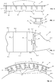
figures 1 et 2 , un dispositif de guidage 10 comprend : - un rail 12 configuré pour supporter un outil et qui se déforme pour s'étendre selon une première direction parallèle à la direction de travail de l'outil,
- une pluralité de ventouses 14 régulièrement réparties selon la première direction et qui sont chacune configurées pour se fixer de manière temporaire sur une surface,
- pour chaque ventouse 14, une liaison ventouse/rail rigide 16 entre la ventouse 14 et le rail 12.
- Classiquement, un fuselage d'un aéronef comprend plusieurs tronçons mis bout à bout au niveau de plans transversaux et présentant chacun une surface extérieure. Lorsque l'opération réalisée se fait selon une direction de travail parallèle à un plan transversal de l'aéronef, le dispositif de guidage 10 suit alors le profil d'une surface présentant un rayon de courbure dans la première direction.
- Cependant, certains tronçons de fuselage présentent des surfaces dites non-développables. Certaines de ces surfaces non-développables sont à double rayon de courbure et présentent notamment un premier rayon dans une direction parallèle à un plan transversal de l'aéronef et un deuxième rayon de courbure dans une deuxième direction perpendiculaire à un plan transversal de l'aéronef.
- Lorsque le dispositif de guidage 10 est positionné sur un tronçon de fuselage présentant une surface non-développable, il épouse les formes de la surface et tend naturellement à s'écarter par rapport à la direction de travail que doit suivre l'outil. Ainsi, une première extrémité du dispositif de guidage 10 est disposée à proximité de la direction de travail alors que la seconde extrémité du dispositif de guidage 10 est écartée de la direction de travail. Pour certains tronçons du fuselage, l'écart entre la seconde extrémité du dispositif de guidage 10 et la direction de travail que doit suivre l'outil est trop important pour être compensé par les dimensions de l'outil. De plus, en raison de cet écart, le rail 12 peut présenter une torsion qui bloque le déplacement de l'outil le long du rail et le dispositif de guidage 10 peut interférer avec d'autres éléments positionnés autour du fuselage.
- Dans un tel cas d'un tronçon du fuselage présentant une surface non-développable, le dispositif de guidage 10 ne peut pas être positionné parallèlement à un plan transversal car dans cette position toute la surface des ventouses n'est pas en contact avec la surface du fuselage 18.
- Comme illustré sur la
figure 2 , seule une extrémité 14.1 de chaque ventouse est en contact avec la surface du fuselage 18, l'autre extrémité 14.2 étant écartée. - Le document
EP2384842 décrit un rail pour guider un appareil de soudage. Ce rail est relié à une pluralité de supports chacun d'eux étant relié au rail par une liaison rotule. Selon ce document, l'axe de pivotement entre le rail et chaque support est positionné au niveau de la liaison rotule, entre le support et le rail, et il est écarté de la surface du support configurée pour être plaquée sur la surface de travail. Cette configuration ne permet pas de s'adapter à un changement de courbure de la surface de travail. - La présente invention vise à remédier aux inconvénients de l'art antérieur.
- A cet effet, l'invention a pour objet un dispositif de guidage comprenant :
- un rail qui s'étend selon une direction et qui comprend une surface de support configurée pour porter et guider un outil selon une direction de travail parallèle à la direction,
- une pluralité de patins répartis selon la direction, chaque patin étant configuré pour occuper un état actif dans lequel le patin est immobilisé et un état repos dans lequel le patin peut bouger,
- pour chaque patin au moins une liaison patin/rail reliant chaque patin et le rail, caractérisé en ce que chaque liaison patin/rail est configurée pour permettre à chaque patin de pivoter indépendamment des autres patins par rapport au rail autour d'un axe de pivotement parallèle à la direction.
- Ainsi, selon l'invention, le rail peut être positionné parallèlement à la direction de travail sur une surface extérieure d'un fuselage non-développable, chaque patin étant plaqué sur toute sa surface sur la surface extérieure du fuselage.
- Selon une autre caractéristique, l'axe de pivotement est positionné sur une première face du patin configurée pour être plaquée sur une surface de travail sur laquelle est rapportée le dispositif de guidage en fonctionnement, à équidistance des bords latéraux du patin.
- Selon une variante, chaque liaison patin/rail comprend une première partie solidaire du rail, une deuxième partie solidaire du patin, les première et deuxième parties ayant des formes qui coopèrent, configurées pour former une liaison glissière en arc de cercle avec un centre positionné sur l'axe de pivotement.
- Ainsi, le centre de rotation de chaque patin est confondu avec le centre de la première face du patin et chaque patin reste immobile lorsque le patin est plaqué sur la surface de travail.
- Selon une autre caractéristique, la deuxième partie comprend un corps relié au patin qui présente un trou oblong comportant un chant supérieur et un chant inférieur coaxiaux et la première partie comprend une traverse reliée au rail et une tête solidaire de la traverse, ladite tête comportant une face supérieure configurée pour être plaquée et glissée sur le chant supérieur du trou oblong et une face inférieure configurée pour être plaquée et glissée sur le chant inférieur du trou oblong.
- Selon un mode de réalisation :
- la tête est reliée à la traverse par un support et décalée vers l'axe de pivotement par rapport à la traverse,
- la traverse comprend, sur une première face orientée vers la tête, au moins une découpe cylindrique coaxiale à la face supérieure de la tête,
- le corps comprend une face supérieure orientée vers la traverse coaxiale au chant du trou oblong, et l'écartement entre la face supérieure et le chant supérieur du trou oblong est égal à l'écartement entre la face supérieure de la tête et la découpe de la traverse.
- Selon une autre caractéristique, chaque patin est relié au rail par deux liaisons patin/rail, décalées selon la direction, les supports reliant les têtes aux traverses étant positionnés entre les corps des deux liaisons patin/rail.
- D'autres caractéristiques et avantages ressortiront de la description de l'invention qui va suivre, description donnée à titre d'exemple uniquement, en regard des dessins annexés sur lesquels :
- La
figure 1 est une vue latérale d'un dispositif de guidage qui illustre un mode de réalisation de l'invention, - La
figure 2 est une coupe selon la ligne II-II du dispositif de guidage visible sur lafigure 1 , - La
figure 3 est une représentation schématique d'un dispositif de guidage positionné sur une surface de travail qui illustre un mode de réalisation de l'invention, - La
figure 4 est une coupe schématique du dispositif de guidage visible sur lafigure 3 , - La
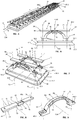
figure 5 est une vue en perspective d'un dispositif de guidage qui illustre une variante de l'invention, - La
figure 6 est une vue de face du dispositif de guidage visible sur lafigure 5 , - La
figure 7 est une vue en perspective d'un patin et d'une liaison patin/rail du dispositif de guidage visible sur lafigure 5 , - La
figure 8 est une vue en perspective d'une première partie de la liaison patin/rail visible sur lafigure 7 , et - La
figure 9 est une vue en perspective d'une deuxième partie de la liaison patin/rail visible sur lafigure 7 . - La
figure 3 illustre un fuselage 20 d'un aéronef qui comprend plusieurs tronçons 22.1 à 22.4 mis bout à bout au niveau de plans transversaux P1, P2, P3 et présentant chacun une surface extérieure 24.1 à 24.4. Pour certains tronçons 22.1 et 22.2, la surface extérieure 24.1, 24.4 est sensiblement cylindrique et comprend un rayon de courbure. Pour d'autres tronçons 22.3 et 22.4, la surface extérieure 24.3 et 24.4 est non-développable et présente plusieurs rayons de courbure, notamment deux rayons de courbure dans le cas du tronçon 22.3. - Un dispositif de guidage 26 est positionné sur la surface extérieure 24.3 dite surface de travail, à proximité du plan transversal P3, parallèlement au plan transversal P3.
- Ce dispositif de guidage 26 s'étend selon une direction D entre une première extrémité 26.1 et une seconde extrémité 26.2 et comprend :
- un rail 28 qui s'étend de la première extrémité 26.1 jusqu'à la seconde extrémité 26.2 et qui comprend une surface de support 29 configurée pour porter et guider un outil 30 selon une direction de travail 31 parallèle à la direction D,
- une pluralité de patins 32 répartis selon la direction D, chaque patin 32 étant configuré pour occuper un état actif dans lequel il est immobilisé par rapport à la surface de travail 24.3 et un état repos dans lequel il peut bouger par rapport à la surface de travail 24.3,
- pour chaque patin 32, au moins une liaison patin/rail 34 configurée pour relier chaque patin 32 au rail 28.
- Le rail 28 est configuré pour occuper un état conformé dans lequel la surface de support 29 du rail 28 est parallèle à la surface de travail 24.3. Ainsi, le rail 28 peut se déformer selon un premier rayon de courbure R1 visible sur la
figure 4 et selon un deuxième rayon de courbure R2, dans un plan perpendiculaire à la direction D, visible sur lafigure 5 . Le rail n'est pas plus décrit car il peut être identique aux rails de l'art antérieur. - Le rail 28 comprend un plan médian vertical PMV qui est parallèle à la direction D, équidistant des bords 28.1 et 28.2 du rail 28 et perpendiculaire à la surface support 29 du rail 28.
- Le patin 32 comprend des bords latéraux 32.1 et 32.2 parallèles à la direction D et positionnés également à équidistance du plan médian vertical PMV.
- Selon un mode de réalisation visible sur les
figures 6 et 7 , chaque patin 32 comprend une semelle 36 configurée pour se déformer selon les premier et deuxième rayons de courbure R1 et R2 qui comprend une première face 36.1 configurée pour être plaquée sur la surface de travail 24.3 et une deuxième face 36.2 opposée à la première face 36.1 et orientée vers le rail 28, ainsi que deux blocs rigides 38.1 et 38.2 positionnées sur la deuxième face 36.2 et solidaires de la semelle 36. Les deux blocs rigides 38.1 et 38.2 sont décalés selon la direction D pour permettre à la semelle 36 de se déformer selon le premier rayon de courbure R1. - Selon un mode de fonctionnement, chaque patin 32 est de type à ventouse.
- L'invention n'est pas limitée à ce mode de réalisation pour les patins 32. Ainsi, les patins peuvent être de type électromagnétique, l'immobilisation du patin par rapport à la surface de travail 24.3 n'étant pas générée par dépression mais par aimantation. D'autres solutions techniques sont envisageables pour immobiliser les patins 32 de manière temporaire par rapport à la surface de travail 24.3.
- Avantageusement, le dispositif de guidage comprend au moins une commande pour contrôler l'état des patins 32.
- Selon une caractéristique de l'invention, chaque liaison patin/rail 34 est configurée pour permettre à chaque patin 32 de pivoter indépendamment des autres patins 32 par rapport au rail 28 autour d'un axe de pivotement A34 parallèle à la direction D et positionné dans le plan médian vertical PMV.
- Selon cet agencement, le rail 28 peut être positionné parallèlement à un plan transversal sur une surface de travail avec un double rayon de courbure, chaque patin 32 étant plaqué sur toute la première face 36.1 contre la surface de travail 24.3. Ainsi, la direction D du rail 28 est parallèle à la direction de travail 31 que doit suivre l'outil 30.
- Chaque liaison patin/rail 34 comprend une première partie 40 solidaire du rail 28 et une deuxième partie 42 solidaire du patin 32.
- Selon une première variante, la première partie 40 est reliée à la deuxième partie 42 par un axe de rotation 44 qui forme l'axe de pivotement A34.
- Selon une deuxième variante visible sur les
figures 5 à 9 , les première et deuxième parties 40, 42 ont des formes qui coopèrent, configurées pour former une liaison glissière 46 en arc de cercle avec un centre positionné sur l'axe de pivotement A34. - Selon une caractéristique de l'invention, l'axe de pivotement A34 est positionné sur la première face 36.1, à équidistance des bords latéraux 32.1 et 32.2 du patin 32. En fonctionnement, l'axe de pivotement A34 est positionné à une interface entre le patin 32 et la surface de travail 24.3. Ce positionnement combiné au fait que l'axe de pivotement A34 est à équidistance des bords latéraux 32.1 et 32.2 de chaque patin 32 permet de conformer les patins 32 sur la surface de travail 24.3 sans générer de déplacement du centre de chaque patin 32.
- Selon un mode de réalisation de cette deuxième variante, la deuxième partie 42 comprend un corps 48 en arc de cercle qui présente un trou oblong 50 en arc de cercle avec un centre de courbure positionné sur l'axe de pivotement A34. Le trou oblong 50 présente un chant supérieur 50S et un chant inférieur 50I coaxiaux ayant le même axe confondu avec l'axe de pivotement A34.
- Le rayon de la forme en arc de cercle du trou oblong 50 est déterminé de manière à ce que l'axe de pivotement A34 soit positionné sur la première face 36.1, à équidistance des bords latéraux 32.1 et 32.2 du patin 32.
- Le corps 48 comprend deux extrémités 48.1 et 48.2 reliées au patin 32 par tous moyens de fixation 52 appropriés, comme des vis ou des boulons par exemple, et maintenues écartées du patin grâce à deux entretoises 54, une à chaque extrémité 48.1, 48.2.
- En complément, la première partie 40 comprend une traverse 56 reliée au rail 28 par tous moyens de fixation 58 appropriés, comme des vis ou des boulons par exemple, et une tête 60 solidaire de la traverse 56, ladite tête 60 comportant des formes adaptées pour coulisser dans le trou oblong 50 de la deuxième partie 42.
- Ainsi, la tête 60 comprend une face supérieure 60S configurée pour être plaquée et glissée sur le chant supérieur 50S du trou oblong 50 ainsi qu'une face inférieure 60I configurée pour être plaquée et glissée sur le chant inférieur 50I du trou oblong 50. La tête 60 a une longueur inférieure à celle du trou oblong 50 pour lui permettre de coulisser dans le trou oblong 50. Selon un mode de réalisation, la tête 60 est décalée par rapport à la traverse 56 vers l'axe de pivotement A34, selon une direction radiale (perpendiculaire à l'axe de pivotement A34). Dans ce cas, la tête 60 est reliée à la traverse 56 par un support 62. Avantageusement, la traverse 56, la tête 60 et le support 62 sont une seule et même pièce.
- Selon un mode de réalisation, la traverse 56 comprend un décrochement 64 au niveau du support 62 pour loger un système de guidage 66, comme une crémaillère par exemple, prévu au niveau du rail 28.
- La traverse 56 comprend, sur une première face 68 orientée vers la tête 60, au moins une découpe 70 cylindrique coaxiale à la face supérieure 60S de la tête 60. En complément, le corps 48 comprend une face supérieure 48S orientée vers la traverse 56 coaxiale au chant 50S du trou oblong 50. L'écartement entre la face supérieure 48S et le chant supérieur 50S du trou oblong 50 est égal à l'écartement entre la face supérieure 60S de la tête 60 et la découpe 70 de la traverse 56. Ainsi, en fonctionnement, trois surfaces 60I, 60S, 70 de la première partie 40 coulissent respectivement sur trois surfaces 50I, 50S, 48S de la deuxième partie 42 ce qui confère un guidage optimal entre la première partie 40 et la deuxième partie 42.
- Selon un mode de réalisation, chaque patin 32 est relié au rail 28 par deux liaisons patin/rail 34, décalées selon la direction D, une pour chaque bloc rigide 38. Pour chaque patin 32, les supports 62 reliant les têtes 60 aux traverses 56 sont positionnés entre les corps 48 pour éviter que les têtes 60 sortent des trous oblongs 50.
- Selon l'invention, le rail 28 peut être positionné dans une direction de travail 31 maîtrisée. Par ailleurs, grâce à l'invention, un espace technique est agencé entre le rail 28 et les patins 32 pour l'intégration de fonctions supplémentaires nécessaire aux systèmes de gestion du vide, d'apport électrique ou autre.
Claims (6)
- Dispositif de guidage comprenant :- un rail (28) qui s'étend selon une direction (D) et qui comprend une surface de support (29) configurée pour porter et guider un outil (30) selon une direction de travail (31) parallèle à la direction (D),- une pluralité de patins (32) répartis selon la direction (D), chaque patin (32) étant configuré pour occuper un état actif dans lequel le patin (32) est immobilisé et un état repos dans lequel le patin (32) peut bouger,- pour chaque patin (32) au moins une liaison patin/rail (34) reliant chaque patin (32) et le rail (28),chaque liaison patin/rail (34) étant configurée pour permettre à chaque patin (32) de pivoter indépendamment des autres patins (32) par rapport au rail (28) autour d'un axe de pivotement (A34) parallèle à la direction (D), caractérisé en ce que l'axe de pivotement (A34) est positionné sur une première face (36.1) du patin (32) configurée pour être plaquée sur une surface de travail (24.3) sur laquelle est rapportée le dispositif de guidage en fonctionnement.
- Dispositif de guidage selon la revendication 1, caractérisé en ce que l'axe de pivotement (A34) est positionné à équidistance des bords latéraux (32.1, 32.2) du patin (32).
- Dispositif de guidage selon la revendication précédente, caractérisé en ce que chaque liaison patin/rail (34) comprend une première partie (40) solidaire du rail (28), une deuxième partie (42) solidaire du patin (32), les première et deuxième parties (40, 42) ayant des formes qui coopèrent, configurées pour former une liaison glissière (46) en arc de cercle avec un centre positionné sur l'axe de pivotement (A34).
- Dispositif de guidage selon la revendication précédente, caractérisé en ce que la deuxième partie (42) comprend un corps (48) relié au patin (32) qui présente un trou oblong (50) comportant un chant supérieur (50S) et un chant inférieur (50I) coaxiaux et en ce que la première partie (40) comprend une traverse (56) reliée au rail (28) et une tête (60) solidaire de la traverse (56), ladite tête (60) comportant une face supérieure (60S) configurée pour être plaquée et glissée sur le chant supérieur (50S) du trou oblong (50) ainsi qu'une face inférieure (60I) configurée pour être plaquée et glissée sur le chant inférieur (50I) du trou oblong (50).
- Dispositif de guidage selon la revendication précédente, caractérisé en ce que la tête (60) est reliée à la traverse (56) par un support (62) et décalée vers l'axe de pivotement (A34) par rapport à la traverse (56), en ce que la traverse (56) comprend, sur une première face (68) orientée vers la tête (60), au moins une découpe (70) cylindrique coaxiale à la face supérieure (60S) de la tête (60), en ce que le corps (48) comprend une face supérieure (48S) orientée vers la traverse (56) coaxiale au chant (50S) du trou oblong (50) et en ce que l'écartement entre la face supérieure (48S) et le chant supérieur (50S) du trou oblong (50) est égal à l'écartement entre la face supérieure (60S) de la tête (60) et la découpe (70) de la traverse (56).
- Dispositif de guidage selon la revendication précédente, caractérisé en ce que chaque patin (32) est relié au rail (28) par deux liaisons patin/rail (34), décalées selon la direction (D), les supports (62) reliant les têtes (60) aux traverses (56) étant positionnés entre les corps (48) des deux liaisons patin/rail (34).
Applications Claiming Priority (1)
| Application Number | Priority Date | Filing Date | Title |
|---|---|---|---|
| FR1663119A FR3061054B1 (fr) | 2016-12-22 | 2016-12-22 | Dispositif de guidage adapte pour se positionner sur une surface a double rayon de courbure |
Publications (2)
| Publication Number | Publication Date |
|---|---|
| EP3338942A1 EP3338942A1 (fr) | 2018-06-27 |
| EP3338942B1 true EP3338942B1 (fr) | 2021-09-01 |
Family
ID=58347629
Family Applications (1)
| Application Number | Title | Priority Date | Filing Date |
|---|---|---|---|
| EP17205371.2A Not-in-force EP3338942B1 (fr) | 2016-12-22 | 2017-12-05 | Dispositif de guidage adapte pour se positionner sur une surface a double rayon de courbure |
Country Status (4)
| Country | Link |
|---|---|
| US (1) | US10500710B2 (fr) |
| EP (1) | EP3338942B1 (fr) |
| CN (1) | CN108216681B (fr) |
| FR (1) | FR3061054B1 (fr) |
Families Citing this family (5)
| Publication number | Priority date | Publication date | Assignee | Title |
|---|---|---|---|---|
| FR3061054B1 (fr) * | 2016-12-22 | 2019-06-14 | Airbus Operations | Dispositif de guidage adapte pour se positionner sur une surface a double rayon de courbure |
| DE102018210507A1 (de) * | 2018-06-27 | 2020-01-02 | Airbus Operations Gmbh | Montagesystem für eine automatisierte Innenmontage eines Flugzeugrumpfes |
| CN114871799B (zh) * | 2022-05-18 | 2023-07-11 | 中航沈飞民用飞机有限责任公司 | 一种面向自动钻铆模块化柔性工装 |
| US12187456B2 (en) | 2023-03-31 | 2025-01-07 | Airbus Operations Gmbh | System and method for a manufacturing environment with robotic system mounts having one or more end effectors positioned sympathetic to the underlying manufactured item |
| US12521868B2 (en) | 2023-03-31 | 2026-01-13 | Airbus Operations Gmbh | Apparatuses and processes for working on a part |
Family Cites Families (17)
| Publication number | Priority date | Publication date | Assignee | Title |
|---|---|---|---|---|
| US3844468A (en) * | 1973-06-27 | 1974-10-29 | Crc Crose Int Inc | Universal carriage apparatus for operating on pipes and analogous workpieces of various diameters |
| US6158666A (en) * | 1997-11-26 | 2000-12-12 | Banks; David P. | Vacuum fastened guide and method for supporting tooling on a component |
| US7216408B2 (en) * | 2004-05-27 | 2007-05-15 | The Boeing Company | Flexible rail multiaxis machine tool and method |
| US7134649B2 (en) * | 2004-05-27 | 2006-11-14 | The Boeing Company | Conformal vacuum cup apparatus and method |
| US7578642B2 (en) * | 2005-08-05 | 2009-08-25 | The Boeing Corporation | Flexible single rail drilling system |
| DE102007009641B4 (de) * | 2007-02-26 | 2013-12-12 | Eads Deutschland Gmbh | Vorrichtung zur Führung eines Fräswerkzeugs sowie deren Verwendung |
| DE102010028593B4 (de) * | 2010-05-05 | 2011-12-15 | SCHWEIßTECHNISCHE LEHR- UND VERSUCHSANSTALT HALLE GMBH | Einrichtung zur Herstellung von entlang räumlicher, in einer Ebene abwickelbarer Verschneidungskurven verlaufenden Schweißnähten für überschwere Rohrfachwerkverbindungen |
| US9512864B2 (en) * | 2013-02-25 | 2016-12-06 | The Boeing Company | Method and system for conforming assembly systems to contours of curved surfaces |
| FR3009351B1 (fr) * | 2013-08-01 | 2015-08-07 | Airbus Operations Sas | Outillage pour le maintien simultane de plusieurs clips de fixation contre un element de cadre de fuselage d'aeronef |
| FR3009274A1 (fr) * | 2013-08-01 | 2015-02-06 | Airbus Operations Sas | Element de cadre de fuselage d'aeronef integrant des languettes pour la fixation de raidisseurs |
| FR3009352B1 (fr) * | 2013-08-01 | 2016-01-01 | Airbus Operations Sas | Outillage pour le maintien simultane de plusieurs clips de fixation contre un element de cadre de fuselage d'aeronef |
| US9656319B2 (en) * | 2013-11-13 | 2017-05-23 | The Boeing Company | Positioning system for electromagnetic riveting |
| FR3016606B1 (fr) * | 2014-01-21 | 2016-02-19 | Airbus Operations Sas | Procede de fabrication d'une partie d'un fuselage d'un aeronef et outillage pour la mise en oeuvre dudit procede |
| US9682429B2 (en) * | 2015-04-22 | 2017-06-20 | The Boeing Company | Reaction tool and method for forming openings in an aircraft fuselage joint |
| US9663248B2 (en) * | 2015-05-06 | 2017-05-30 | The Boeing Company | Workbench assembly |
| FR3061054B1 (fr) * | 2016-12-22 | 2019-06-14 | Airbus Operations | Dispositif de guidage adapte pour se positionner sur une surface a double rayon de courbure |
| CN106514082B (zh) * | 2016-12-29 | 2019-10-18 | 天津大学 | 一种用于船体表面自动化焊接的磁吸式柔性轨道 |
-
2016
- 2016-12-22 FR FR1663119A patent/FR3061054B1/fr not_active Expired - Fee Related
-
2017
- 2017-12-05 EP EP17205371.2A patent/EP3338942B1/fr not_active Not-in-force
- 2017-12-07 US US15/834,414 patent/US10500710B2/en active Active
- 2017-12-20 CN CN201711387862.4A patent/CN108216681B/zh not_active Expired - Fee Related
Also Published As
| Publication number | Publication date |
|---|---|
| US20180178370A1 (en) | 2018-06-28 |
| EP3338942A1 (fr) | 2018-06-27 |
| FR3061054B1 (fr) | 2019-06-14 |
| US10500710B2 (en) | 2019-12-10 |
| FR3061054A1 (fr) | 2018-06-29 |
| CN108216681B (zh) | 2022-11-01 |
| CN108216681A (zh) | 2018-06-29 |
Similar Documents
| Publication | Publication Date | Title |
|---|---|---|
| FR3061054B1 (fr) | Dispositif de guidage adapte pour se positionner sur une surface a double rayon de courbure | |
| EP1544035B1 (fr) | Ensemble de partie avant de véhicule automobile comportant des moyens perfectionnés de fixation et d'ajustement en position, et véhicule automobile pourvu d'un tel ensemble | |
| EP1098737B1 (fr) | Dispositif de centrage et de bridage d'un ensemble de tolerie ou de pieces mecaniques | |
| WO2016001507A1 (fr) | Dispositif de serrage de pieces destinees a etre assemblees | |
| EP1612087A1 (fr) | Véhicule prévu pour se déplacer le long d'au moins un rail | |
| EP4034446B1 (fr) | Dispositif d'articulation de véhicule articulé, véhicule et procédé de réglage correspondants | |
| WO2009077702A1 (fr) | Traverse de planche de bord pour véhicule automobile et véhicule comportant une telle traverse | |
| EP4311782B1 (fr) | Système de manipulation d'une coque latérale d'un aéronef en vue d'un assemblage d'un corps de fuselage de l'aéronef et procédé d'assemblage d'un corps de fuselage d'un aéronef | |
| FR3100231A1 (fr) | Dispositif de prehension d’un panneau d’un tronçon de fuselage d’un aeronef | |
| FR2897009A1 (fr) | Procede de positionnement d'un outil d'assemblage a l'extremite d'un bras articule et dispositif pour sa mise en oeuvre | |
| EP2969749B1 (fr) | Trein d'atterrissage d'aéronef muni d'un galet réglable | |
| FR3009987A1 (fr) | Support d'outil integrant un systeme de guidage espace de l'outil et dispositif d'usinage integrant ledit support d'outil | |
| EP4281618B1 (fr) | Ensemble et procédé d'alignement automatique de rails | |
| EP1350981B1 (fr) | Frein de stationnement pour véhicule et son dispositif de commande | |
| FR3094047A3 (fr) | Liaison entre deux éléments montés articulés l’un à l’autre. | |
| WO2019211350A1 (fr) | Procédé et système de maintien a came d'un arbre en positionnement bistable | |
| EP3735369B1 (fr) | Vehicule equipe d'un appui-cric dans le renfort de pied avant et appui-cric pour un tel vehicule | |
| FR2889094A1 (fr) | Dispositif de liaison a deformabilite sensiblement mono directionnelle | |
| FR3040903A1 (fr) | Dispositif de mise en maintien en position d’une piece | |
| EP3122576B1 (fr) | Véhicule automobile comportant des moyens de guidage de fixation de train roulant | |
| EP3917819B1 (fr) | Véhicule doté d'éléments de renfort de traverses latérales avant | |
| FR3012565A1 (fr) | Dispositif de sortie verticale d’ecran grace a un verin a gaz | |
| FR2929229A1 (fr) | Manipulateur pour le montage des ouvrants sur la caisse d'un vehicule automobile | |
| FR3132038A1 (fr) | Table de ferrage modulaire pour le ferrage de pièces de carrosserie automobile. | |
| FR2912940A1 (fr) | Dispositif et procede d'assistance et de realisation de travaux mecaniques sur une piece montee sur un support |
Legal Events
| Date | Code | Title | Description |
|---|---|---|---|
| PUAI | Public reference made under article 153(3) epc to a published international application that has entered the european phase |
Free format text: ORIGINAL CODE: 0009012 |
|
| STAA | Information on the status of an ep patent application or granted ep patent |
Free format text: STATUS: THE APPLICATION HAS BEEN PUBLISHED |
|
| AK | Designated contracting states |
Kind code of ref document: A1 Designated state(s): AL AT BE BG CH CY CZ DE DK EE ES FI FR GB GR HR HU IE IS IT LI LT LU LV MC MK MT NL NO PL PT RO RS SE SI SK SM TR |
|
| AX | Request for extension of the european patent |
Extension state: BA ME |
|
| STAA | Information on the status of an ep patent application or granted ep patent |
Free format text: STATUS: REQUEST FOR EXAMINATION WAS MADE |
|
| 17P | Request for examination filed |
Effective date: 20190102 |
|
| RBV | Designated contracting states (corrected) |
Designated state(s): AL AT BE BG CH CY CZ DE DK EE ES FI FR GB GR HR HU IE IS IT LI LT LU LV MC MK MT NL NO PL PT RO RS SE SI SK SM TR |
|
| GRAP | Despatch of communication of intention to grant a patent |
Free format text: ORIGINAL CODE: EPIDOSNIGR1 |
|
| STAA | Information on the status of an ep patent application or granted ep patent |
Free format text: STATUS: GRANT OF PATENT IS INTENDED |
|
| INTG | Intention to grant announced |
Effective date: 20210617 |
|
| GRAS | Grant fee paid |
Free format text: ORIGINAL CODE: EPIDOSNIGR3 |
|
| GRAA | (expected) grant |
Free format text: ORIGINAL CODE: 0009210 |
|
| STAA | Information on the status of an ep patent application or granted ep patent |
Free format text: STATUS: THE PATENT HAS BEEN GRANTED |
|
| AK | Designated contracting states |
Kind code of ref document: B1 Designated state(s): AL AT BE BG CH CY CZ DE DK EE ES FI FR GB GR HR HU IE IS IT LI LT LU LV MC MK MT NL NO PL PT RO RS SE SI SK SM TR |
|
| REG | Reference to a national code |
Ref country code: GB Ref legal event code: FG4D Free format text: NOT ENGLISH |
|
| REG | Reference to a national code |
Ref country code: CH Ref legal event code: EP Ref country code: AT Ref legal event code: REF Ref document number: 1425712 Country of ref document: AT Kind code of ref document: T Effective date: 20210915 |
|
| REG | Reference to a national code |
Ref country code: DE Ref legal event code: R096 Ref document number: 602017045085 Country of ref document: DE |
|
| REG | Reference to a national code |
Ref country code: IE Ref legal event code: FG4D Free format text: LANGUAGE OF EP DOCUMENT: FRENCH |
|
| REG | Reference to a national code |
Ref country code: LT Ref legal event code: MG9D |
|
| REG | Reference to a national code |
Ref country code: NL Ref legal event code: MP Effective date: 20210901 |
|
| PG25 | Lapsed in a contracting state [announced via postgrant information from national office to epo] |
Ref country code: NO Free format text: LAPSE BECAUSE OF FAILURE TO SUBMIT A TRANSLATION OF THE DESCRIPTION OR TO PAY THE FEE WITHIN THE PRESCRIBED TIME-LIMIT Effective date: 20211201 Ref country code: ES Free format text: LAPSE BECAUSE OF FAILURE TO SUBMIT A TRANSLATION OF THE DESCRIPTION OR TO PAY THE FEE WITHIN THE PRESCRIBED TIME-LIMIT Effective date: 20210901 Ref country code: FI Free format text: LAPSE BECAUSE OF FAILURE TO SUBMIT A TRANSLATION OF THE DESCRIPTION OR TO PAY THE FEE WITHIN THE PRESCRIBED TIME-LIMIT Effective date: 20210901 Ref country code: BG Free format text: LAPSE BECAUSE OF FAILURE TO SUBMIT A TRANSLATION OF THE DESCRIPTION OR TO PAY THE FEE WITHIN THE PRESCRIBED TIME-LIMIT Effective date: 20211201 Ref country code: LT Free format text: LAPSE BECAUSE OF FAILURE TO SUBMIT A TRANSLATION OF THE DESCRIPTION OR TO PAY THE FEE WITHIN THE PRESCRIBED TIME-LIMIT Effective date: 20210901 Ref country code: SE Free format text: LAPSE BECAUSE OF FAILURE TO SUBMIT A TRANSLATION OF THE DESCRIPTION OR TO PAY THE FEE WITHIN THE PRESCRIBED TIME-LIMIT Effective date: 20210901 Ref country code: RS Free format text: LAPSE BECAUSE OF FAILURE TO SUBMIT A TRANSLATION OF THE DESCRIPTION OR TO PAY THE FEE WITHIN THE PRESCRIBED TIME-LIMIT Effective date: 20210901 Ref country code: HR Free format text: LAPSE BECAUSE OF FAILURE TO SUBMIT A TRANSLATION OF THE DESCRIPTION OR TO PAY THE FEE WITHIN THE PRESCRIBED TIME-LIMIT Effective date: 20210901 |
|
| REG | Reference to a national code |
Ref country code: AT Ref legal event code: MK05 Ref document number: 1425712 Country of ref document: AT Kind code of ref document: T Effective date: 20210901 |
|
| PG25 | Lapsed in a contracting state [announced via postgrant information from national office to epo] |
Ref country code: PL Free format text: LAPSE BECAUSE OF FAILURE TO SUBMIT A TRANSLATION OF THE DESCRIPTION OR TO PAY THE FEE WITHIN THE PRESCRIBED TIME-LIMIT Effective date: 20210901 Ref country code: LV Free format text: LAPSE BECAUSE OF FAILURE TO SUBMIT A TRANSLATION OF THE DESCRIPTION OR TO PAY THE FEE WITHIN THE PRESCRIBED TIME-LIMIT Effective date: 20210901 Ref country code: GR Free format text: LAPSE BECAUSE OF FAILURE TO SUBMIT A TRANSLATION OF THE DESCRIPTION OR TO PAY THE FEE WITHIN THE PRESCRIBED TIME-LIMIT Effective date: 20211202 |
|
| PG25 | Lapsed in a contracting state [announced via postgrant information from national office to epo] |
Ref country code: AT Free format text: LAPSE BECAUSE OF FAILURE TO SUBMIT A TRANSLATION OF THE DESCRIPTION OR TO PAY THE FEE WITHIN THE PRESCRIBED TIME-LIMIT Effective date: 20210901 |
|
| PG25 | Lapsed in a contracting state [announced via postgrant information from national office to epo] |
Ref country code: IS Free format text: LAPSE BECAUSE OF FAILURE TO SUBMIT A TRANSLATION OF THE DESCRIPTION OR TO PAY THE FEE WITHIN THE PRESCRIBED TIME-LIMIT Effective date: 20220101 Ref country code: SM Free format text: LAPSE BECAUSE OF FAILURE TO SUBMIT A TRANSLATION OF THE DESCRIPTION OR TO PAY THE FEE WITHIN THE PRESCRIBED TIME-LIMIT Effective date: 20210901 Ref country code: SK Free format text: LAPSE BECAUSE OF FAILURE TO SUBMIT A TRANSLATION OF THE DESCRIPTION OR TO PAY THE FEE WITHIN THE PRESCRIBED TIME-LIMIT Effective date: 20210901 Ref country code: RO Free format text: LAPSE BECAUSE OF FAILURE TO SUBMIT A TRANSLATION OF THE DESCRIPTION OR TO PAY THE FEE WITHIN THE PRESCRIBED TIME-LIMIT Effective date: 20210901 Ref country code: PT Free format text: LAPSE BECAUSE OF FAILURE TO SUBMIT A TRANSLATION OF THE DESCRIPTION OR TO PAY THE FEE WITHIN THE PRESCRIBED TIME-LIMIT Effective date: 20220103 Ref country code: NL Free format text: LAPSE BECAUSE OF FAILURE TO SUBMIT A TRANSLATION OF THE DESCRIPTION OR TO PAY THE FEE WITHIN THE PRESCRIBED TIME-LIMIT Effective date: 20210901 Ref country code: EE Free format text: LAPSE BECAUSE OF FAILURE TO SUBMIT A TRANSLATION OF THE DESCRIPTION OR TO PAY THE FEE WITHIN THE PRESCRIBED TIME-LIMIT Effective date: 20210901 Ref country code: CZ Free format text: LAPSE BECAUSE OF FAILURE TO SUBMIT A TRANSLATION OF THE DESCRIPTION OR TO PAY THE FEE WITHIN THE PRESCRIBED TIME-LIMIT Effective date: 20210901 Ref country code: AL Free format text: LAPSE BECAUSE OF FAILURE TO SUBMIT A TRANSLATION OF THE DESCRIPTION OR TO PAY THE FEE WITHIN THE PRESCRIBED TIME-LIMIT Effective date: 20210901 |
|
| REG | Reference to a national code |
Ref country code: DE Ref legal event code: R097 Ref document number: 602017045085 Country of ref document: DE |
|
| PLBE | No opposition filed within time limit |
Free format text: ORIGINAL CODE: 0009261 |
|
| STAA | Information on the status of an ep patent application or granted ep patent |
Free format text: STATUS: NO OPPOSITION FILED WITHIN TIME LIMIT |
|
| PG25 | Lapsed in a contracting state [announced via postgrant information from national office to epo] |
Ref country code: MC Free format text: LAPSE BECAUSE OF FAILURE TO SUBMIT A TRANSLATION OF THE DESCRIPTION OR TO PAY THE FEE WITHIN THE PRESCRIBED TIME-LIMIT Effective date: 20210901 Ref country code: IT Free format text: LAPSE BECAUSE OF FAILURE TO SUBMIT A TRANSLATION OF THE DESCRIPTION OR TO PAY THE FEE WITHIN THE PRESCRIBED TIME-LIMIT Effective date: 20210901 Ref country code: DK Free format text: LAPSE BECAUSE OF FAILURE TO SUBMIT A TRANSLATION OF THE DESCRIPTION OR TO PAY THE FEE WITHIN THE PRESCRIBED TIME-LIMIT Effective date: 20210901 |
|
| REG | Reference to a national code |
Ref country code: CH Ref legal event code: PL |
|
| 26N | No opposition filed |
Effective date: 20220602 |
|
| PG25 | Lapsed in a contracting state [announced via postgrant information from national office to epo] |
Ref country code: SI Free format text: LAPSE BECAUSE OF FAILURE TO SUBMIT A TRANSLATION OF THE DESCRIPTION OR TO PAY THE FEE WITHIN THE PRESCRIBED TIME-LIMIT Effective date: 20210901 |
|
| REG | Reference to a national code |
Ref country code: BE Ref legal event code: MM Effective date: 20211231 |
|
| PG25 | Lapsed in a contracting state [announced via postgrant information from national office to epo] |
Ref country code: LU Free format text: LAPSE BECAUSE OF NON-PAYMENT OF DUE FEES Effective date: 20211205 Ref country code: IE Free format text: LAPSE BECAUSE OF NON-PAYMENT OF DUE FEES Effective date: 20211205 |
|
| PG25 | Lapsed in a contracting state [announced via postgrant information from national office to epo] |
Ref country code: BE Free format text: LAPSE BECAUSE OF NON-PAYMENT OF DUE FEES Effective date: 20211231 |
|
| PG25 | Lapsed in a contracting state [announced via postgrant information from national office to epo] |
Ref country code: LI Free format text: LAPSE BECAUSE OF NON-PAYMENT OF DUE FEES Effective date: 20211231 Ref country code: CH Free format text: LAPSE BECAUSE OF NON-PAYMENT OF DUE FEES Effective date: 20211231 |
|
| PG25 | Lapsed in a contracting state [announced via postgrant information from national office to epo] |
Ref country code: HU Free format text: LAPSE BECAUSE OF FAILURE TO SUBMIT A TRANSLATION OF THE DESCRIPTION OR TO PAY THE FEE WITHIN THE PRESCRIBED TIME-LIMIT; INVALID AB INITIO Effective date: 20171205 |
|
| PG25 | Lapsed in a contracting state [announced via postgrant information from national office to epo] |
Ref country code: CY Free format text: LAPSE BECAUSE OF FAILURE TO SUBMIT A TRANSLATION OF THE DESCRIPTION OR TO PAY THE FEE WITHIN THE PRESCRIBED TIME-LIMIT Effective date: 20210901 |
|
| PGFP | Annual fee paid to national office [announced via postgrant information from national office to epo] |
Ref country code: GB Payment date: 20231220 Year of fee payment: 7 |
|
| PGFP | Annual fee paid to national office [announced via postgrant information from national office to epo] |
Ref country code: FR Payment date: 20231222 Year of fee payment: 7 Ref country code: DE Payment date: 20231214 Year of fee payment: 7 |
|
| PG25 | Lapsed in a contracting state [announced via postgrant information from national office to epo] |
Ref country code: MK Free format text: LAPSE BECAUSE OF FAILURE TO SUBMIT A TRANSLATION OF THE DESCRIPTION OR TO PAY THE FEE WITHIN THE PRESCRIBED TIME-LIMIT Effective date: 20210901 |
|
| PG25 | Lapsed in a contracting state [announced via postgrant information from national office to epo] |
Ref country code: TR Free format text: LAPSE BECAUSE OF FAILURE TO SUBMIT A TRANSLATION OF THE DESCRIPTION OR TO PAY THE FEE WITHIN THE PRESCRIBED TIME-LIMIT Effective date: 20210901 |
|
| PG25 | Lapsed in a contracting state [announced via postgrant information from national office to epo] |
Ref country code: MT Free format text: LAPSE BECAUSE OF FAILURE TO SUBMIT A TRANSLATION OF THE DESCRIPTION OR TO PAY THE FEE WITHIN THE PRESCRIBED TIME-LIMIT Effective date: 20210901 |
|
| REG | Reference to a national code |
Ref country code: DE Ref legal event code: R119 Ref document number: 602017045085 Country of ref document: DE |
|
| GBPC | Gb: european patent ceased through non-payment of renewal fee |
Effective date: 20241205 |
|
| PG25 | Lapsed in a contracting state [announced via postgrant information from national office to epo] |
Ref country code: DE Free format text: LAPSE BECAUSE OF NON-PAYMENT OF DUE FEES Effective date: 20250701 |
|
| PG25 | Lapsed in a contracting state [announced via postgrant information from national office to epo] |
Ref country code: GB Free format text: LAPSE BECAUSE OF NON-PAYMENT OF DUE FEES Effective date: 20241205 |
|
| PG25 | Lapsed in a contracting state [announced via postgrant information from national office to epo] |
Ref country code: FR Free format text: LAPSE BECAUSE OF NON-PAYMENT OF DUE FEES Effective date: 20241231 |