EP3338941B1 - Machine à transfert rotatif - Google Patents
Machine à transfert rotatif Download PDFInfo
- Publication number
- EP3338941B1 EP3338941B1 EP17209227.2A EP17209227A EP3338941B1 EP 3338941 B1 EP3338941 B1 EP 3338941B1 EP 17209227 A EP17209227 A EP 17209227A EP 3338941 B1 EP3338941 B1 EP 3338941B1
- Authority
- EP
- European Patent Office
- Prior art keywords
- unit
- workpiece
- cell
- machining
- plate
- Prior art date
- Legal status (The legal status is an assumption and is not a legal conclusion. Google has not performed a legal analysis and makes no representation as to the accuracy of the status listed.)
- Active
Links
- 238000003754 machining Methods 0.000 claims description 68
- 238000000034 method Methods 0.000 claims description 13
- 238000012545 processing Methods 0.000 description 100
- 238000012546 transfer Methods 0.000 description 18
- 238000007514 turning Methods 0.000 description 17
- 238000013461 design Methods 0.000 description 7
- 238000003801 milling Methods 0.000 description 7
- 238000005520 cutting process Methods 0.000 description 4
- 238000012805 post-processing Methods 0.000 description 4
- 238000005553 drilling Methods 0.000 description 3
- 230000001419 dependent effect Effects 0.000 description 2
- 238000007781 pre-processing Methods 0.000 description 2
- 238000005452 bending Methods 0.000 description 1
- 230000001276 controlling effect Effects 0.000 description 1
- 125000004122 cyclic group Chemical group 0.000 description 1
- 238000011161 development Methods 0.000 description 1
- 230000018109 developmental process Effects 0.000 description 1
- 238000000227 grinding Methods 0.000 description 1
- 238000004519 manufacturing process Methods 0.000 description 1
- 108090000623 proteins and genes Proteins 0.000 description 1
- 230000001105 regulatory effect Effects 0.000 description 1
- 230000001360 synchronised effect Effects 0.000 description 1
Images


Classifications
-
- B—PERFORMING OPERATIONS; TRANSPORTING
- B23—MACHINE TOOLS; METAL-WORKING NOT OTHERWISE PROVIDED FOR
- B23Q—DETAILS, COMPONENTS, OR ACCESSORIES FOR MACHINE TOOLS, e.g. ARRANGEMENTS FOR COPYING OR CONTROLLING; MACHINE TOOLS IN GENERAL CHARACTERISED BY THE CONSTRUCTION OF PARTICULAR DETAILS OR COMPONENTS; COMBINATIONS OR ASSOCIATIONS OF METAL-WORKING MACHINES, NOT DIRECTED TO A PARTICULAR RESULT
- B23Q16/00—Equipment for precise positioning of tool or work into particular locations not otherwise provided for
- B23Q16/02—Indexing equipment
- B23Q16/08—Indexing equipment having means for clamping the relatively movable parts together in the indexed position
- B23Q16/10—Rotary indexing
-
- B—PERFORMING OPERATIONS; TRANSPORTING
- B23—MACHINE TOOLS; METAL-WORKING NOT OTHERWISE PROVIDED FOR
- B23B—TURNING; BORING
- B23B29/00—Holders for non-rotary cutting tools; Boring bars or boring heads; Accessories for tool holders
- B23B29/24—Tool holders for a plurality of cutting tools, e.g. turrets
-
- B—PERFORMING OPERATIONS; TRANSPORTING
- B23—MACHINE TOOLS; METAL-WORKING NOT OTHERWISE PROVIDED FOR
- B23B—TURNING; BORING
- B23B3/00—General-purpose turning-machines or devices, e.g. centre lathes with feed rod and lead screw; Sets of turning-machines
- B23B3/30—Turning-machines with two or more working-spindles, e.g. in fixed arrangement
-
- B—PERFORMING OPERATIONS; TRANSPORTING
- B23—MACHINE TOOLS; METAL-WORKING NOT OTHERWISE PROVIDED FOR
- B23Q—DETAILS, COMPONENTS, OR ACCESSORIES FOR MACHINE TOOLS, e.g. ARRANGEMENTS FOR COPYING OR CONTROLLING; MACHINE TOOLS IN GENERAL CHARACTERISED BY THE CONSTRUCTION OF PARTICULAR DETAILS OR COMPONENTS; COMBINATIONS OR ASSOCIATIONS OF METAL-WORKING MACHINES, NOT DIRECTED TO A PARTICULAR RESULT
- B23Q1/00—Members which are comprised in the general build-up of a form of machine, particularly relatively large fixed members
- B23Q1/01—Frames, beds, pillars or like members; Arrangement of ways
- B23Q1/012—Portals
-
- B—PERFORMING OPERATIONS; TRANSPORTING
- B23—MACHINE TOOLS; METAL-WORKING NOT OTHERWISE PROVIDED FOR
- B23Q—DETAILS, COMPONENTS, OR ACCESSORIES FOR MACHINE TOOLS, e.g. ARRANGEMENTS FOR COPYING OR CONTROLLING; MACHINE TOOLS IN GENERAL CHARACTERISED BY THE CONSTRUCTION OF PARTICULAR DETAILS OR COMPONENTS; COMBINATIONS OR ASSOCIATIONS OF METAL-WORKING MACHINES, NOT DIRECTED TO A PARTICULAR RESULT
- B23Q1/00—Members which are comprised in the general build-up of a form of machine, particularly relatively large fixed members
- B23Q1/25—Movable or adjustable work or tool supports
- B23Q1/44—Movable or adjustable work or tool supports using particular mechanisms
- B23Q1/56—Movable or adjustable work or tool supports using particular mechanisms with sliding pairs only, the sliding pairs being the first two elements of the mechanism
- B23Q1/60—Movable or adjustable work or tool supports using particular mechanisms with sliding pairs only, the sliding pairs being the first two elements of the mechanism two sliding pairs only, the sliding pairs being the first two elements of the mechanism
- B23Q1/62—Movable or adjustable work or tool supports using particular mechanisms with sliding pairs only, the sliding pairs being the first two elements of the mechanism two sliding pairs only, the sliding pairs being the first two elements of the mechanism with perpendicular axes, e.g. cross-slides
- B23Q1/621—Movable or adjustable work or tool supports using particular mechanisms with sliding pairs only, the sliding pairs being the first two elements of the mechanism two sliding pairs only, the sliding pairs being the first two elements of the mechanism with perpendicular axes, e.g. cross-slides a single sliding pair followed perpendicularly by a single sliding pair
- B23Q1/626—Movable or adjustable work or tool supports using particular mechanisms with sliding pairs only, the sliding pairs being the first two elements of the mechanism two sliding pairs only, the sliding pairs being the first two elements of the mechanism with perpendicular axes, e.g. cross-slides a single sliding pair followed perpendicularly by a single sliding pair followed perpendicularly by a single sliding pair
-
- B—PERFORMING OPERATIONS; TRANSPORTING
- B23—MACHINE TOOLS; METAL-WORKING NOT OTHERWISE PROVIDED FOR
- B23Q—DETAILS, COMPONENTS, OR ACCESSORIES FOR MACHINE TOOLS, e.g. ARRANGEMENTS FOR COPYING OR CONTROLLING; MACHINE TOOLS IN GENERAL CHARACTERISED BY THE CONSTRUCTION OF PARTICULAR DETAILS OR COMPONENTS; COMBINATIONS OR ASSOCIATIONS OF METAL-WORKING MACHINES, NOT DIRECTED TO A PARTICULAR RESULT
- B23Q39/00—Metal-working machines incorporating a plurality of sub-assemblies, each capable of performing a metal-working operation
- B23Q39/04—Metal-working machines incorporating a plurality of sub-assemblies, each capable of performing a metal-working operation the sub-assemblies being arranged to operate simultaneously at different stations, e.g. with an annular work-table moved in steps
- B23Q39/042—Metal-working machines incorporating a plurality of sub-assemblies, each capable of performing a metal-working operation the sub-assemblies being arranged to operate simultaneously at different stations, e.g. with an annular work-table moved in steps with circular arrangement of the sub-assemblies
- B23Q39/044—Metal-working machines incorporating a plurality of sub-assemblies, each capable of performing a metal-working operation the sub-assemblies being arranged to operate simultaneously at different stations, e.g. with an annular work-table moved in steps with circular arrangement of the sub-assemblies having at least one tool station cooperating with each work holder, e.g. multi-spindle lathes
-
- B—PERFORMING OPERATIONS; TRANSPORTING
- B23—MACHINE TOOLS; METAL-WORKING NOT OTHERWISE PROVIDED FOR
- B23Q—DETAILS, COMPONENTS, OR ACCESSORIES FOR MACHINE TOOLS, e.g. ARRANGEMENTS FOR COPYING OR CONTROLLING; MACHINE TOOLS IN GENERAL CHARACTERISED BY THE CONSTRUCTION OF PARTICULAR DETAILS OR COMPONENTS; COMBINATIONS OR ASSOCIATIONS OF METAL-WORKING MACHINES, NOT DIRECTED TO A PARTICULAR RESULT
- B23Q7/00—Arrangements for handling work specially combined with or arranged in, or specially adapted for use in connection with, machine tools, e.g. for conveying, loading, positioning, discharging, sorting
- B23Q7/02—Arrangements for handling work specially combined with or arranged in, or specially adapted for use in connection with, machine tools, e.g. for conveying, loading, positioning, discharging, sorting by means of drums or rotating tables or discs
-
- B—PERFORMING OPERATIONS; TRANSPORTING
- B23—MACHINE TOOLS; METAL-WORKING NOT OTHERWISE PROVIDED FOR
- B23Q—DETAILS, COMPONENTS, OR ACCESSORIES FOR MACHINE TOOLS, e.g. ARRANGEMENTS FOR COPYING OR CONTROLLING; MACHINE TOOLS IN GENERAL CHARACTERISED BY THE CONSTRUCTION OF PARTICULAR DETAILS OR COMPONENTS; COMBINATIONS OR ASSOCIATIONS OF METAL-WORKING MACHINES, NOT DIRECTED TO A PARTICULAR RESULT
- B23Q7/00—Arrangements for handling work specially combined with or arranged in, or specially adapted for use in connection with, machine tools, e.g. for conveying, loading, positioning, discharging, sorting
- B23Q7/04—Arrangements for handling work specially combined with or arranged in, or specially adapted for use in connection with, machine tools, e.g. for conveying, loading, positioning, discharging, sorting by means of grippers
- B23Q7/047—Arrangements for handling work specially combined with or arranged in, or specially adapted for use in connection with, machine tools, e.g. for conveying, loading, positioning, discharging, sorting by means of grippers the gripper supporting the workpiece during machining
-
- B—PERFORMING OPERATIONS; TRANSPORTING
- B23—MACHINE TOOLS; METAL-WORKING NOT OTHERWISE PROVIDED FOR
- B23Q—DETAILS, COMPONENTS, OR ACCESSORIES FOR MACHINE TOOLS, e.g. ARRANGEMENTS FOR COPYING OR CONTROLLING; MACHINE TOOLS IN GENERAL CHARACTERISED BY THE CONSTRUCTION OF PARTICULAR DETAILS OR COMPONENTS; COMBINATIONS OR ASSOCIATIONS OF METAL-WORKING MACHINES, NOT DIRECTED TO A PARTICULAR RESULT
- B23Q7/00—Arrangements for handling work specially combined with or arranged in, or specially adapted for use in connection with, machine tools, e.g. for conveying, loading, positioning, discharging, sorting
- B23Q7/10—Arrangements for handling work specially combined with or arranged in, or specially adapted for use in connection with, machine tools, e.g. for conveying, loading, positioning, discharging, sorting by means of magazines
-
- B—PERFORMING OPERATIONS; TRANSPORTING
- B23—MACHINE TOOLS; METAL-WORKING NOT OTHERWISE PROVIDED FOR
- B23B—TURNING; BORING
- B23B3/00—General-purpose turning-machines or devices, e.g. centre lathes with feed rod and lead screw; Sets of turning-machines
- B23B3/06—Turning-machines or devices characterised only by the special arrangement of constructional units
- B23B3/065—Arrangements for performing other machining operations, e.g. milling, drilling
-
- B—PERFORMING OPERATIONS; TRANSPORTING
- B23—MACHINE TOOLS; METAL-WORKING NOT OTHERWISE PROVIDED FOR
- B23Q—DETAILS, COMPONENTS, OR ACCESSORIES FOR MACHINE TOOLS, e.g. ARRANGEMENTS FOR COPYING OR CONTROLLING; MACHINE TOOLS IN GENERAL CHARACTERISED BY THE CONSTRUCTION OF PARTICULAR DETAILS OR COMPONENTS; COMBINATIONS OR ASSOCIATIONS OF METAL-WORKING MACHINES, NOT DIRECTED TO A PARTICULAR RESULT
- B23Q39/00—Metal-working machines incorporating a plurality of sub-assemblies, each capable of performing a metal-working operation
- B23Q2039/008—Machines of the lathe type
-
- Y—GENERAL TAGGING OF NEW TECHNOLOGICAL DEVELOPMENTS; GENERAL TAGGING OF CROSS-SECTIONAL TECHNOLOGIES SPANNING OVER SEVERAL SECTIONS OF THE IPC; TECHNICAL SUBJECTS COVERED BY FORMER USPC CROSS-REFERENCE ART COLLECTIONS [XRACs] AND DIGESTS
- Y10—TECHNICAL SUBJECTS COVERED BY FORMER USPC
- Y10T—TECHNICAL SUBJECTS COVERED BY FORMER US CLASSIFICATION
- Y10T29/00—Metal working
- Y10T29/51—Plural diverse manufacturing apparatus including means for metal shaping or assembling
- Y10T29/5124—Plural diverse manufacturing apparatus including means for metal shaping or assembling with means to feed work intermittently from one tool station to another
- Y10T29/5125—Stock turret
-
- Y—GENERAL TAGGING OF NEW TECHNOLOGICAL DEVELOPMENTS; GENERAL TAGGING OF CROSS-SECTIONAL TECHNOLOGIES SPANNING OVER SEVERAL SECTIONS OF THE IPC; TECHNICAL SUBJECTS COVERED BY FORMER USPC CROSS-REFERENCE ART COLLECTIONS [XRACs] AND DIGESTS
- Y10—TECHNICAL SUBJECTS COVERED BY FORMER USPC
- Y10T—TECHNICAL SUBJECTS COVERED BY FORMER US CLASSIFICATION
- Y10T82/00—Turning
- Y10T82/25—Lathe
- Y10T82/2524—Multiple
Definitions
- the invention relates to a rotary indexing machine and a method for operating a rotary indexing machine.
- a rotary indexing machine with at least one indexing plate, which is provided in at least one operating state for receiving and transporting at least one workpiece, and with at least one indexing cell, which has at least one receiving unit with at least two opposite receiving elements, which are used to jointly receive the at least a workpiece from the cycle plate are provided, and has at least one processing unit for processing the workpiece picked up by means of the pick-up unit.
- a machine with at least one cycle plate which is provided in at least one operating state for receiving and transporting at least one workpiece
- at least one cycle cell which has at least one receiving unit with at least two opposite receiving elements, which are used to receive the at least one workpiece together are provided from the clock plate, and has at least one machining unit for machining the workpiece picked up by the pick-up unit.
- the object of the invention is in particular to provide a generic device with improved properties in terms of precision and workability of the workpieces.
- the object is achieved according to the invention by the features of patent claim 1, while advantageous configurations and developments of the invention can be found in the dependent claims.
- the invention is based on a rotary indexing machine with at least one indexing plate, which is provided in at least one operating state for receiving and transporting at least one workpiece, and with at least one cycle cell, which has at least one receiving unit with at least two opposite receiving elements, which form a common receptacle of the at least one workpiece from the cycle plate are provided, and at least one processing unit for processing the workpiece picked up by the pick-up unit.
- the at least one cycle cell has at least one bridge unit, which extends at least partially beyond the cycle plate in the axial direction and is intended to guide the at least two receiving elements of the receiving unit in a common coordinate system, with the processing unit being attached to the bridge unit is arranged.
- the bridge unit is preferably provided for guiding the at least two receiving elements in guides.
- the guides of the at least two receiving elements of the bridge unit are preferably aligned in a defined manner relative to one another.
- the coordinate system of the bridge unit is particularly preferably different from a coordinate system of the cycle plate of the rotary transfer machine.
- a "rotary indexing machine” is to be understood in particular as a machine, preferably a machine tool, with at least one indexing plate, in which at least one workpiece, in particular several workpieces, are clamped in at least one operating state.
- this is to be understood in particular as a machine with a plurality of processing stations, in particular cycle cells, for processing the at least one workpiece.
- the workpiece is preferably transported from processing station to processing station by means of the cycle plate.
- the processing stations are particularly preferably arranged in a circle around the clock plate.
- the machine also has at least one feed unit for equipping the indexing plate and at least one removal unit for removing the machined workpieces from the indexing plate.
- Rotary indexing machines are also known as indexing drum machines or rotary transfer machines.
- a “clock plate” is to be understood in particular as a workpiece holder that is preferably at least partially circular and is provided for receiving and transporting workpieces.
- this is to be understood in particular as a rotatably drivable workpiece holder which is provided to move the workpieces from one cycle cell to the next cycle cell.
- the cycle plate preferably comprises at least one gripping unit, preferably arranged on a circumference of the cycle plate, which is provided for directly picking up a workpiece.
- the clock plate comprises several preferably evenly distributed gripping units in the circumferential direction. Under "intended” should in particular specifically programmed, designed and/or understood to be equipped.
- a “cycle cell” is to be understood in particular as a machining cell of the rotary indexing machine, which is provided for cyclic machining of a workpiece.
- the cycle cell is preferably provided for processing one workpiece per cycle.
- the cycle cell is preferably provided for carrying out one processing step of the rotary transfer machine.
- Various processing steps that appear reasonable to a person skilled in the art are conceivable, such as drilling, milling, turning, reaming, grinding, sawing, separating and/or other, in particular metal-cutting, chipping or dividing manufacturing processes.
- a “receiving unit” is to be understood in particular as a unit which is provided for the temporary removal of a workpiece from the cycle plate.
- this is to be understood in particular as a unit which is provided for processing a workpiece by the cycle cell in order to temporarily remove a workpiece from the cycle plate.
- the unit is particularly preferably provided for the purpose of removing a workpiece from the indexing plate for processing during one cycle of the rotary transfer machine and inserting it back into the indexing plate after processing.
- the fact that "the two opposing receiving elements are provided for jointly receiving the at least one workpiece from the cycle plate” should be understood to mean in particular that the receiving elements are provided for jointly, in particular simultaneously, receiving the at least one workpiece.
- the receiving elements are preferably provided for gripping the at least one workpiece from opposite directions and clamping it between them.
- the at least one workpiece is preferably clamped between the two opposing receiving elements for receiving.
- the receiving elements each have a centering element, in particular a centering mandrel, which is provided to interact, in particular to engage, with a centering element, in particular with a centering bore, of the at least one workpiece for receiving.
- a "processing unit” is to be understood in particular as a unit of the clock cell which is used for direct processing of the recorded Workpiece is provided.
- the processing unit preferably comprises at least one processing tool for processing the workpiece. In principle, the processing unit can also include several processing tools.
- the processing unit is preferably provided in particular for machining the at least one workpiece by machining, cutting and/or dividing.
- the workpiece is processed by the processing unit during one cycle of the processing machine.
- machining tools that appear sensible to a person skilled in the art are conceivable, such as drills, milling cutters, cutting discs and/or lathe tools.
- a “bridge unit” is to be understood in particular as an inherently rigid unit which serves as a supporting frame for the clock cell.
- this is to be understood in particular as meaning a frame that carries the receiving unit and the processing unit of the cycle cell at least essentially without deformation.
- the bridge unit is preferably designed differently from a supporting structure of the rotary indexing machine.
- the clock cell is particularly preferably designed to be self-supporting by means of the bridge unit.
- "At least essentially free of deformation” is to be understood in particular as meaning that the clock cell, in a theoretically one-sidedly supported state, has a vertical deflection of a maximum of 0.25 mm, preferably a maximum of 0.03 mm, over an entire extension, in particular due to bending stress. preferably of a maximum of 0.01 mm and particularly preferably of a maximum of 0.005 mm.
- the fact that "the bridge unit extends in the axial direction at least partially beyond the clock plate” is to be understood in this context in particular as meaning that the bridge unit is arranged at least partially radially next to the clock plate.
- the bridge unit extends at least partially, in particular completely, over an axial extension of the clock plate, viewed along a rotation axis of the clock plate.
- the bridge unit preferably overlaps the timing plate in the axial direction.
- the bridge unit is intended to guide the at least two receiving elements of the receiving unit in a common coordinate system
- the bridge unit has at least two guides for the receiving elements, the positions of which are determined via a common coordinate system, in particular the bridge unit.
- the at least two receiving elements are independent of a position are positioned relative to one another in a defined manner within the rotary indexing machine via the bridge unit.
- the at least two receiving elements can preferably be moved in a defined manner relative to one another via the bridge unit, independently of a position within the rotary indexing machine.
- the configuration of the rotary indexing machine according to the invention makes it possible in particular to provide a rotary indexing machine with an advantageously precise indexing cell in which the workpiece is picked up.
- an advantageously simple and reliable machinability of the workpiece held can be achieved.
- a position of the workpiece within the cycle cell can be known and ensured.
- an advantageously precise processing can be made possible.
- the coordinate system preferably enables precise machining of the workpiece independently of the geometric, thermal or vibration-related errors in the coordinate system of the cycle plate.
- the cycle cell can be used to machine, in particular lathe-machine, a rotationally symmetrical area in particular in such a way that it has an advantageously precise concentricity and/or coaxiality requirement that cannot be achieved in the firmly clamped state.
- the at least one bridge unit is provided for receiving the at least two receiving elements of the receiving unit in a defined manner, guided relative to one another.
- the at least two receiving elements are preferably designed to be immovable in the radial direction of the clock plate relative to the bridge unit.
- the bridge unit particularly preferably has at least two opposite guides, which are each provided for a guide of one of the at least two receiving elements.
- at least two opposite guides which are each provided for a guide of one of the at least two receiving elements.
- the at least one processing unit is permanently connected to the at least one bridge unit.
- Processing unit arranged on the bridge unit.
- the processing unit is preferably partially movable relative to the bridge unit.
- the processing unit works in a coordinate system of the bridge unit.
- the processing unit works in the same coordinate system as the recording elements of the recording unit.
- the workpiece can be approached particularly precisely by means of the processing unit.
- advantageously precise machining can be made possible.
- precise machining can be made possible, in which inaccuracies due to geometric, thermal or vibration-related errors can be reliably avoided.
- the at least one machining unit is provided for turning the workpiece picked up by means of the pick-up unit.
- the workpiece is preferably driven in rotation about a central axis by means of the receiving unit in a state received by the receiving unit.
- the at least two receiving elements are preferably driven in rotation for machining the at least one workpiece.
- the clock cell is particularly preferably formed by a precision rotary cell. In this way, in particular, a particularly reliable rotary clock cell can be provided. In particular, a particularly precise cycle cell can be provided, in which case an entire circumference of the workpiece can preferably be turned, since the workpiece is removed from the cycle plate.
- the at least one machining unit has at least two tools for machining the workpiece.
- the machining unit preferably has at least two turning tools, in particular turning tools.
- the tools of the machining unit are preferably fixed in position relative to one another.
- the at least two tools are particularly preferably arranged together on a tool carrier which is designed to be movable relative to the bridge unit.
- the tools can preferably be used alternately for turning or milling.
- the desired tool can be selected by positioning an axis, in particular the Y axis, of the tool carrier. In this way, in particular, an advantageously fast and flexible processing of the Workpiece can be achieved. In this way, the workpiece can preferably be machined in the same cycle cell using different tools.
- the at least one cycle cell has at least one hydraulic unit, which is provided for moving a tool carrier of the at least one machining unit transversely to an axis of rotation of the cycle plate.
- the tool carrier is preferably intended to be moved relative to the bridge unit by means of the hydraulic unit.
- the tool carrier is preferably moved towards the workpiece by means of the hydraulic unit in order to carry out a turning operation or a milling operation, transversely to an axis of rotation of the cycle plate.
- the cycle cell also has at least one electric drive, which is provided to move a tool carrier of the at least one machining unit perpendicular to an axis of rotation of the cycle plate.
- the tool carrier is preferably intended to be moved relative to the bridge unit by means of the hydraulic unit and the electric drive.
- the tool carrier is preferably equipped with three degrees of freedom, ie in particular along an X-axis, Y-axis and Z-axis.
- the three degrees of freedom are particularly preferably controlled with the hydraulic unit and/or the electric drive.
- the hydraulic unit preferably has at least one hydraulic axle drive and/or the at least one electric drive has at least one electric axle drive on the X axis, on the Y axis and/or on the Z axis.
- the hydraulic axle drive is preferably designed as a plunger cylinder.
- hydraulic unit is to be understood in particular as meaning a unit with at least one hydraulic actuator, in particular with at least one hydraulic element, such as a hydraulic cylinder. It should preferably be understood in particular as a drive unit which is provided for moving the tool carrier. In this way, in particular, an advantageously precise movement of the tool carrier and thus also an advantageously precise machining of the workpiece can be made possible. Furthermore, an advantageously compact clock cell can be provided by a corresponding structure. This preferably makes the compact design possible in the first place.
- the at least one bridge unit viewed in a plane perpendicular to an axis of rotation of the clock plate, at least partially has the shape of a sector of a circle.
- the bridge unit viewed in a plane perpendicular to an axis of rotation of the clock disk, tapers towards an axis of rotation of the clock disk.
- the bridge unit is preferably at least partially in the form of a sector of a circular cylinder.
- “the at least one bridge unit at least partially has the shape of a sector of a circle” should be understood to mean in particular that the bridge unit, viewed in a plane perpendicular to an axis of rotation of the clock plate, has at least two side edges which converge to a point.
- the side edges preferably intersect at least approximately in a main extension plane of the bridge unit.
- the side edges preferably each form an outer edge of the bridge unit, viewed in a plane perpendicular to an axis of rotation of the clock plate.
- a “main extension plane” of a structural unit is to be understood in particular as a plane which is parallel to a largest side surface of an imaginary cuboid which just completely encloses the structural unit and in particular runs through the center point of the cuboid.
- an advantageously compact design of the clock cell can be achieved. In this way it can be achieved in particular that neighboring clock cells are not affected by the clock cell. This can preferably be achieved in that two clock cells can be integrated in direct succession as consecutive clock stations in the rotary indexing machine.
- the rotary indexing machine has at least one additional clock cell, which is designed at least essentially identically to the at least one clock cell.
- the further clock cell is preferably also formed by a precision rotary cell.
- the clock cell and the further clock cell are preferably arranged directly adjacent to one another.
- the clock cells particularly preferably form clock stations that follow one another in direct succession.
- the further clock cell is preferably configured completely identically to the at least one clock cell. In this way, in particular, an advantageous rotary indexing machine can be provided.
- At least one of the at least two cycle cells be used for pre-processing and/or post-processing of the at least one workpiece.
- One of the at least two cycle cells is preferably provided for pre-processing and one of the at least two cycle cells for post-processing of the at least one workpiece.
- advantageously precise machining, in particular turning, of the workpiece can be achieved.
- Large material removals can preferably also be made possible as a result.
- this allows different tools to be used in the two clock cells.
- the at least one clock plate has at least one gripping unit for receiving the workpiece, which gripping unit has at least two gripping surfaces with significantly different radii.
- the gripping unit preferably has two gripping elements which are arranged such that they can move in relation to one another and which form the two gripping surfaces.
- a first radius of the gripping surface preferably corresponds to a radius of the workpiece before processing by the clock cell and a second radius of the gripping surface corresponds to a radius of the workpiece after processing by the clock cell.
- a “gripping unit” is to be understood in particular as a unit which is provided for receiving a workpiece.
- the gripping unit is preferably arranged on an outer radius of the timing plate.
- the cycle plate particularly preferably has a plurality of gripping units which are each provided for receiving a workpiece.
- the at least one cycle cell is designed to be movable relative to the cycle plate.
- the clock cell preferably has at least one drive and at least one guide, by means of which the clock cell can move relative to the clock plate.
- the clock cell can preferably be moved in a direction perpendicular to an axis of rotation of the clock plate.
- the clock cell can therefore in particular be moved towards or away from the clock disk.
- the cycle cell particularly preferably has at least one drive and at least one guide, in particular a gantry drive, in order to pick up the workpiece from a fixed clamping position of the cycle plate, in particular from a first coordinate system if necessary, to be returned again without the need for another transport device.
- an advantageous mobility can be achieved without components of the clock cell having to be moved relative to one another.
- an advantageously rigid system can be provided.
- the invention is based on a cycle cell of the rotary transfer machine, with at least one receiving unit, which has at least two opposing receiving elements, which are provided for jointly receiving the at least one workpiece from the cycle plate of the rotary transfer machine, with at least one processing unit for processing the workpiece received in the receiving unit and with at least one bridge unit which extends at least partially in the axial direction beyond the cycle plate of the rotary indexing machine and which is intended to guide the at least two receiving elements of the receiving unit in a common coordinate system, with the processing unit being arranged on the bridge unit and wherein the at least one bridging unit is provided for receiving the at least two receiving elements of the receiving unit in a defined manner, guided relative to one another, the bridging unit having at least two opposite guides has genes, which are each provided for guiding one of the at least two receiving elements.
- the invention is based on a method for operating the rotary indexing machine. It is proposed that in a removal step a cycle cell of the rotary transfer machine is brought into a removal position via a cycle plate of the rotary transfer machine and a workpiece is removed from the cycle plate by means of a receiving unit of the cycle cell.
- the workpiece is preferably removed from the coordinate system of the cycle plate, in particular with permanently installed processing stations, and transferred to a new coordinate system of the cycle cell.
- an entire lateral surface of the workpiece can preferably be machined.
- the workpiece can be moved independently of the cycle plate for machining.
- the workpiece can be driven in rotation.
- the cycle cell in a processing step the cycle cell is brought into a processing position away from the cycle plate and the workpiece is machined by a processing unit of the cycle cell.
- the processing step brought the clock cell with the workpiece in a processing position away from the clock plate.
- free machining of the workpiece can be made possible.
- an advantageous accessibility of the workpiece can be made possible by the cycle cell. A collision with the timing plate can preferably be avoided in this way.
- the cycle cell in a feeding step the cycle cell is brought into the removal position via the cycle plate and the workpiece is placed in a gripping unit of the cycle plate by means of the receiving unit of the cycle cell.
- the workpiece is preferably taken over by the receiving unit of the cycle cell by means of the gripping unit of the cycle plate.
- the removal step, the processing step and/or the feeding step be carried out during one cycle of the rotary indexing machine.
- the removal step, the processing step and the feeding step are preferably carried out during one cycle of the rotary indexing machine. In this way, in particular, advantageously rapid processing of the workpiece can be provided by the rotary indexing machine.
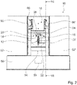
- the figures 1 , 2 and 3 show a rotary indexing machine 10.
- the rotary indexing machine 10 is provided for clocked processing of workpieces 14.
- the rotary indexing machine 10 has a housing 50 and two drive areas 52, 52' enclosed by the housing 50.
- a processing space 54 is arranged between the two drive areas 52, 52'.
- the processing space 54 can be closed by a cover that is not visible any further.
- the rotary indexing machine 10 also has an indexing plate 12 .
- the clock plate 12 is formed by a rotary clock plate.
- the clock plate 12 is in the processing space 54 arranged.
- the timing plate 12 is designed to be rotatable about an axis of rotation 36 .
- the clock plate 12 can be driven in rotation about the axis of rotation 36 via a drive unit that is not visible any further.
- the clock plate 12 is provided for receiving and transporting workpieces 14 .
- the clock plate 12 has an essentially circular base body 56 .
- the clock plate 12 has at least one gripping unit 38 for receiving a workpiece 14 .
- the timing plate 12 has a number of gripping units 38 .
- the timing plate 12 has ten gripping units 38, for example.
- the gripping units 38 each form a clamping station of the cycle plate 12 .
- the gripping units 38 are of identical design.
- the gripping units 38 are arranged on an outer circumference of the base body 56 .
- the gripping units 38 are each provided for receiving a workpiece 14 .
- the gripping units 38 are each provided for firmly clamping a workpiece 14 .
- the gripping units 38 of the clock plate 12 each have two gripping surfaces 40, 42 with significantly different radii.
- the gripping units 38 each have two gripping elements 64, 66 which are designed to be movable relative to one another.
- the gripping elements 64, 66 of a gripping unit 38 each form the gripping surfaces 40, 42 on sides facing one another.
- Both gripping elements 64, 66 each have a gripping surface 40 with a large radius and a gripping surface 42 with a small radius.
- the gripping surface 42 with a small radius is integrated into the gripping surface 40 with a large radius.
- the gripping units 38 can be used to securely grip workpieces 14 with the large radius and workpieces 14 with the small radius.
- the radius of the first gripping surface 40 corresponds to a radius of the workpiece 14 before turning or milling, while the radius of the second gripping surface 42 corresponds to a radius of the workpiece 14 after turning or milling.
- the gripping units 38 each have an actuator (not visible any further) via which the gripping units 38 can be opened and closed.
- the actuator system is provided for moving the gripping elements 64 , 66 .
- the actuators of the gripping units 38 are connected to a computing unit 58 of the rotary indexing machine 10 .
- the processing unit 58 of the rotary indexing machine 10 is provided for controlling and regulating the processes of the rotary indexing machine 10 .
- the cycle plate 12 is provided during operation to turn the workpieces 14 received at an exact angle after each processing cycle of the rotary transfer machine 10 .
- the clock plate 12 together with the mutually facing side surfaces of the drive areas 52, 52', defines a first coordinate system in which the workpieces 14 are accommodated. On All other devices used for machining the workpieces 14 are attached directly or indirectly to the mutually facing side surfaces of the drive areas 52, 52' ( figure 6 and 9 ).
- the rotary indexing machine 10 has a number of stations. The stations are arranged in a circular ring around the timing plate 12 .
- the rotary indexing machine 10 has a loading station 60 .
- the cycle plate 12 is loaded with workpieces 14 at the loading station 60 .
- the workpieces 14 are formed from blanks at the loading station 60 .
- a gripping unit 38 of the cycle plate 12 is equipped with a workpiece 14 per cycle. In particular, an endless blank is fed into the loading station 60 and cut to length after the gripping unit 38 of the cycle plate 12 has been loaded.
- the rotary indexing machine 10 has a plurality of processing stations 62 .
- the processing stations 62 directly adjoin the loading station 60 in the circumferential direction.
- the processing stations 62 are each provided for carrying out different processing steps.
- the cycle plate 12 guides the workpieces 14 one processing station 62 per cycle in the circumferential direction after the processing stations 62 .
- the clock plate 12 rotates at an exact angle and thus moves the clamped workpiece 14 to the next machining stations 62.
- at least one machining station 62 with at least one tool takes place at least one arbitrary, workpiece-dependent machining such as drilling, milling, thread cutting , turning or the like instead.
- An operation does not have to be carried out at each processing station 62 if the clock plate 12 has more stations than processing is necessary.
- only some of the processing stations 62 are provided with cycle cells 16, 16', 92, 94, which carry out an operation.
- the clock cells 92, 94 are formed by drilling clock cells, for example. In principle, however, it would also be conceivable for each processing station 62 to be provided with a clock cell 16, 16', 92, 94 for carrying out an operation on the workpiece 14. Furthermore, the rotary indexing machine 10 has an unloading station 68 at which the workpiece 14 is removed from the indexing plate 12 .
- the unloading station 68 forms a last station before a gripping unit 38 of the cycle plate 12 comes back to the loading station 60 in order to subsequently equip the cycle plate 12 with a new workpiece 14 at the loading station 60 .
- the cycle plate 12 has exactly as many gripping units 38 as the rotary indexing machine has 10 stations has, so that in each cycle a workpiece 14 is supplied at the loading station 60, a finished workpiece 14 is unloaded at the unloading station 68 and an operation is performed at each machining station 62 ( figure 1 and 6 ).
- the rotary transfer machine 10 has a cycle cell 16 .
- the clock cell 16 forms a processing station 62 of the rotary indexing machine 10.
- the clock cell 16 forms a rotary processing station of the rotary indexing machine 10.
- the clock cell 16 is provided for rotary machining of the workpiece 14. In principle, however, a different configuration of the clock cell 16 would also be conceivable, which would appear sensible to a person skilled in the art.
- the rotary transfer machine 10 has a further cycle cell 16 ′, which is designed essentially identically to the cycle cell 16 .
- the additional cycle cell 16' forms a further processing station 62 of the rotary indexing machine 10.
- the additional cycle cell 16' is arranged directly next to the cycle cell 16, for example.
- the further cycle cell 16 ′ forms a processing station 62 which follows the processing station 62 of the cycle cell 16 .
- the two cycle cells 16, 16' are provided for pre-machining and post-machining of the workpiece 14.
- the cycle cell 16 is provided for pre-machining the workpiece 14 . During pre-machining, for example, a large amount of material is removed.
- the further cycle cell 16 ′ is provided for post-processing of the workpiece 14 . During post-processing, only a small amount of material is removed, but a high surface quality is created.
- the clock cells 16, 16' are of identical design. In principle, however, it would be conceivable for clock cells 16, 16' to have different tools which are provided for different requirements. In the following, in particular, only clock cell 16 is described, with the description basically also being applicable to further clock cell 16' ( figure 1 and 6 ).
- the clock cell 16 has a recording unit 18 .
- the receiving unit 18 is provided for temporarily receiving a workpiece 14 .
- the receiving unit 18 is provided for briefly receiving a workpiece 14 during a cycle.
- the receiving unit 18 has two opposing receiving elements 20, 22.
- the receiving elements 20, 22 are provided for receiving a workpiece 14 from the cycle plate 12 together.
- the receiving elements 20, 22 are provided during a cycle, the workpiece 14, which in this cycle to a machining is provided by the clock cell 16 to record from the clock plate 12 together.
- the receiving elements 20, 22 are each formed by a rotary spindle.
- the receiving elements 20, 22 are designed to be rotatably drivable.
- the receiving elements 20, 22 are designed to be rotatably drivable for turning the workpiece 14.
- the receiving elements 20, 22 have, in particular, a drive unit (not visible any further) for driving the receiving elements 20, 22 in rotation.
- the receiving elements 20, 22 are designed to be rotatable about a common axis of rotation 70.
- the receiving elements 20, 22 can be moved in a translatory manner relative to one another in order to receive a workpiece 14 by means of a drive, which is not further visible.
- the receiving elements 20, 22 can be moved towards and away from one another via the drive.
- the receiving elements 20, 22 each have a centering element at a free end.
- the centering elements of the receiving elements 20, 22 are each formed by a centering mandrel.
- the centering elements of the receiving elements 20, 22 are each intended to engage in a centering recess of the workpiece 14.
- the workpieces 14 have centering bores at both ends, into which the centering elements of the receiving elements 20, 22 engage.
- a workpiece 14 that has been picked up is aligned with respect to the receiving unit 18 by the centering elements of the receiving elements 20 , 22 .
- the centering bores in the workpieces 14 are made in a preceding machining station 62 .
- the centering bores it would also be conceivable for the centering bores to be introduced before the clock plate 12 is equipped.
- the receiving elements 20, 22 to have an inner centering cone at their free ends, via which the workpieces 14 are positioned ( Figure 4 and 5 ).
- the clock cell 16 has a bridge unit 26 that extends in the axial direction beyond the clock plate 12 . Viewed in a direction along the axis of rotation 36 of the clock plate 12 , the bridge unit 26 extends over the clock plate 12 . The bridge unit 26 extends parallel to the axis of rotation 36 of the clock plate 12 through the processing space 54. The bridge unit 26 extends between the two drive areas 52, 52' of the rotary indexing machine 10.
- the bridge unit 26 is formed by an inherently rigid, C-shaped frame. Viewed in a plane perpendicular to an axis of rotation 36 of the timing plate 12, the bridge unit 26 partially has the shape of a sector of a circle.
- the bridge unit 26 runs in the plane perpendicular to the Axis of rotation 36 of the clock plate 12 considered, towards the axis of rotation 36 of the clock plate 12 to a point.
- the bridge unit 26 is partially in the form of a sector of a circular cylinder.
- the bridge unit 26 partially defines an outer shape of the clock cell 16.
- the clock cell 16 has, viewed in a plane perpendicular to an axis of rotation 36 of the clock plate 12, partially a circular sector shape.
- the clock cell 16 is shaped in such a way that it fits into a field defined for the processing station 62 , which consists of a circular sector with an interior angle which is composed of 360° divided by the number of stations of the rotary indexing machine 10 .
- the bridge unit 26 is intended to guide the two receiving elements 20, 22 of the receiving unit 18 in a common coordinate system.
- the bridge unit 26 is intended to guide the two receiving elements 20 , 22 of the receiving unit 18 in a coordinate system of the cycle cell 16 .
- the clock cell 16 has a coordinate system different from a coordinate system of the clock plate 12 . In particular, this means that the workpiece 14 can be removed from the coordinate system of the cycle plate 12 with the permanently installed processing stations 62 and transferred to a new coordinate system of the cycle cell 16 .
- the bridge unit 26 is provided for receiving the receiving elements 20, 22 of the receiving unit 18 in a defined manner relative to one another.
- the bridge unit 26 has two opposite guide recesses 72, 74.
- the guide recesses 72, 74 are arranged coaxially with one another.
- the guide recesses 72, 74 are each formed by cylindrical recesses.
- the guide recesses 72, 74 are each introduced in the direction of the axis of rotation 36 of the clock plate 12 projecting extensions of the bridge unit 26.
- the receiving elements 20, 22 are guided in the guide recesses 72, 74 of the bridge unit 26.
- the receiving elements 20, 22 are aligned relative to one another in a defined manner via the guide recesses 72, 74 of the bridge unit 26 ( figure 7 ).
- the clock cell 16 also has a processing unit 24 .
- the machining unit 24 is provided for machining the workpiece 14 picked up by the pick-up unit 18 .
- the machining unit 24 is provided for turning the workpiece 14 picked up by the pick-up unit 18 .
- the processing unit 24 operates in the coordinate system of the clock cell 16.
- the processing unit 24 therefore operates in the same coordinate system as the receiving unit 18.
- the processing unit 24 is firmly connected to the bridge unit 26.
- the processing unit 24 is arranged on the bridge unit 26 .
- the processing unit 24 is aligned in a defined manner relative to the receiving unit 18 via the bridge unit 26 .
- the processing unit 24 is partially movable relative to the bridge unit 26 .
- the machining unit 24 has a tool carrier 34 .
- the tool carrier 34 is designed to be movable relative to the bridge unit 26 .
- the cycle cell 16 has a hydraulic unit that is not further visible.
- the hydraulic unit forms part of the machining unit 24.
- the hydraulic unit is provided for moving a tool carrier 34 of the machining unit 24 relative to the bridge unit 26.
- the clock cell 16 has an electric drive that is not visible any further.
- the electric drive forms part of the machining unit 24.
- the electric drive is provided for moving a tool carrier 34 of the machining unit 24 relative to the bridge unit 26.
- the electric drive is provided for a movement of a tool carrier 34 of the machining unit 24 perpendicular to an axis of rotation 36 of the clock plate 12 .
- the tool carrier 34 is moved towards the workpiece 14 perpendicularly to the axis of rotation 36 of the cycle plate 12 by means of the electric drive in order to carry out a turning operation. Furthermore, the tool carrier 34 is moved relative to the workpiece 14 depending on a machining task.
- the tool carrier 34 has three degrees of freedom in relation to the bridge unit 26 .
- the tool carrier 34 has a degree of freedom relative to the bridge unit 26 along an X-axis, along a Y-axis and along a Z-axis.
- the processing unit 24 has guide units 76 , 78 , 80 .
- a first guide unit 76 guides the tool carrier 34 along a Y-axis.
- the first guide unit 76 comprises guide rails which are firmly connected to the bridge unit 26 .
- the first guide unit 76 comprises guide carriages which are arranged on a first intermediate frame 82 of the processing unit 24 and are guided on the guide rails of the first guide unit 76 .
- a second guide unit 78 guides the tool carrier 34 along an X-axis.
- the second guide unit 78 comprises guide rails which are fixedly connected to the first intermediate frame 82 and guide carriages which are arranged on a second intermediate frame 84 of the processing unit 24 and are guided on the guide rails of the second guide unit 78 .
- a third guide unit 80 guides the tool carrier 34 along a Z-axis.
- the third guide unit 80 includes fixed to the second Guide rails connected between the frames 84 and guide carriages which are arranged on the tool carrier 34 of the machining unit 24 and are guided on the guide rails of the third guide unit 80 .
- a movement of the tool carrier 34 relative to the bridge unit 26 is controlled in part by means of an electric drive, which is not visible in more detail.
- the guide unit 78 is controlled by means of an electric drive that is not further visible.
- the electric drive has, for example, two electric axle drives that are not visible.
- the electric axis drives each serve to separately control the Y-axis and the Z-axis.
- the electric axle drives are arranged on the first and third guide units 76, 80.
- the hydraulic unit has, for example, a hydraulic axle drive that is not visible any further.
- the hydraulic axle drive is arranged on the second guide unit 78 .
- the intermediate frame 84 is controlled by means of the hydraulic final drive.
- the hydraulic axis drive is used for separate control of the X axis.
- the hydraulic axle drive is formed by plunger cylinders. In principle, however, another design that would appear sensible to a person skilled in the art would also be conceivable ( figure 7 and 8th ).
- the processing unit 24 has two tools 28 , 30 for processing the workpiece 14 .
- the tools 28, 30 are each formed by a turning tool.
- the tools 28, 30 are each formed by a turning tool.
- the tools 28, 30 are arranged at a free end of the tool carrier 34.
- the tools 28, 30 are fixed in position relative to one another.
- the tools 28, 30 are arranged in a fixed position on the tool carrier 34.
- the tools 28, 30 are designed to be exchangeable.
- the tools 28, 30 can be used alternately for turning.
- the tools 28, 30 are used separately from each other.
- a tool 28, 30 used is selected depending on a type of tool and/or depending on an orientation of the tool 28, 30 relative to the workpiece 14.
- the currently desired tool 28, 30 is selected by positioning the tool carrier 34 along the X-axis ( figure 7 and 8th ).
- the clock cell 16 is designed to be movable relative to the clock plate 12 .
- the clock cell 16 has a drive unit 86 by means of which the clock cell 16 can be moved relative to the clock plate 12 .
- the clock cell 16 can be moved in a translatory manner by means of the drive unit 86 .
- the clock cell 16 can be activated by means of the drive unit 86 in be moved in a direction perpendicular to the axis of rotation 36 of the clock plate 12 .
- the clock cell 16 can therefore be moved toward the clock plate 12 or away from the clock plate 12 .
- the drive unit 86 is formed by a gantry drive.
- the drive unit 86 has two guide systems 88 which are each arranged on the sides of the bridge unit 26 .
- the guide systems 88 are each arranged on the sides of the bridge unit 26 facing the drive regions 52, 52'.
- the drive unit 86 has a guide system 88 on each side of the bridge unit 26 .
- the guide systems 88 are each formed by guide rails.
- the drive unit 86 has two drive motors 90, 90'.
- the drive motors 90, 90' are arranged on the bridge unit 26.
- the drive motors 90, 90' are operated synchronously.
- the cycle cell 16 can be moved relative to the housing 50 of the rotary transfer machine 10 by means of the drive motors 90, 90' ( figure 7 ).
- a workpiece 14 can be removed from a fixed clamping position of the cycle plate 12 by means of the receiving unit 18 and moved away from the cycle plate 12 for processing. Due to the movement of the entire clock cell 16, the coordinate system of the clock cell 16 remains rigid in itself. By moving the cycle cell 16 relative to the cycle plate 12, a workpiece 14 can therefore be removed by means of the receiving unit 18 from a fixed clamping position of the cycle plate 12 and from a first coordinate system of the cycle plate 12 and, if necessary, returned again without the need for another transport device.
- the figures 2 and 4 show the clock cell 16 in each case in a removal position.
- the cycle cell 16 In the removal position, the cycle cell 16 has a minimum possible distance from the cycle plate 12 in order to grip a workpiece 14 of the cycle plate 12 or to place the workpiece 14 in the cycle plate 12 .
- the Figures 3 and 5 show the clock cell 16 each in a processing position. In the machining position, the cycle cell 16 has a maximum possible distance from the cycle plate 12 in order to be able to freely machine the workpiece 14 ( Figure 4 and 5 ).
- the cycle cell 16 forms a closed system which can be retrofitted into an existing rotary transfer machine 10 .
- figure 10 shows a schematic flowchart of a method for operating the rotary indexing machine 10.
- the method describes an operation of the clock cell 16.
- the method describes a cycle of the cycle cell 16.
- a cycle is with a Removal step 44 started.
- the cycle cell 16 of the rotary transfer machine 10 is brought into a removal position over the cycle plate 12 of the rotary transfer machine 10 and a workpiece 14 is removed from the cycle plate 12 by means of a receiving unit 18 of the cycle cell 16.
- the receiving unit 18 is closed to receive the workpiece 14 .
- the workpiece 14 assigned to the cycle cell 16 in this cycle is picked up.
- the receiving elements 20, 22 can be moved towards one another in a translatory manner by means of the drive, which is not further visible.
- the centering elements of the receiving elements 20, 22 align the workpiece 14 relative to the cycle cell 16 during a recording.
- the centering elements of the receiving elements 20, 22 align the workpiece 14 relative to the coordinate system of the cycle cell 16 during a recording.
- the corresponding gripping unit 38 of the clock plate 12, which grips the corresponding workpiece 14, is then opened.
- the workpiece 14 is removed from the coordinate system of the cycle plate 12 and transferred to the coordinate system of the cycle cell 16 .
- a processing step 46 then follows. In the processing step 46, the clock cell 16 is brought into a processing position away from the clock plate 12 and the workpiece 14 is processed by a processing unit 24 of the clock cell 16 .
- the cycle cell 16 is moved away from the removal position of the cycle plate 12 into a processing position by means of the drive unit 86.
- the receiving elements 20, 22 of the receiving unit 18 are then driven in rotation about the axis of rotation 70 by means of the drive unit, which is not further visible.
- the workpiece 14 is rotated about the axis of rotation 70 as a result of the rotation of the receiving elements 20 , 22 .
- the axis of rotation 70 corresponds in particular to an axis of symmetry of the workpiece 14.
- One of the tools 28, 30 is then moved towards the workpiece 14 by a movement of the tool carrier 34.
- a position of the tool carrier 34 is controlled via the electric drive, which is not further visible.
- the workpiece 14 By approaching one of the tools 28, 30 to the rotating workpiece 14, the workpiece 14 is turned. After the turning, the receiving elements 20, 22 rotate and the workpiece 14 rotates with it. This is followed by a feeding step 48.
- the cycle cell 16 In the feeding step 48, the cycle cell 16 is brought into the removal position over the cycle plate 12 and the workpiece 14 is placed in a gripping unit 38 of the cycle plate 12 by means of the receiving unit 18 of the cycle cell 16.
- the clock cell 16 In the feeding step 48, the clock cell 16 is driven by the drive unit 86 moved from the processing position to the clock plate 12. As a result, the workpiece 14 is arranged between the opened gripping unit 38 .
- the corresponding gripping unit 38 of the clock plate 12, which is provided for receiving the corresponding workpiece 14, is then closed.
- the workpiece 14 is removed from the coordinate system of the clock cell 16 and returned to the coordinate system of the clock plate 12 .
- the workpiece 14 is removed directly from the rotary indexing machine 10 or is transferred in some other way to the first or another coordinate system for processing.
- the receiving unit 18 of the cycle cell 16 is then opened.
- the receiving elements 20, 22 can be moved away from one another in a translatory manner by means of the drive, which is not further visible.
- the cycle is then ended and the cycle plate 12 is rotated further by one station of the rotary transfer machine 10 .
- the cycle of the cycle cell 16 is followed by another cycle of the cycle cell 16 and the method is started again at the removal step 44 .
- the removal step 44, the processing step 46 and the feeding step 48 are carried out during one cycle of the rotary indexing machine 10.
Claims (16)
- Machine cadencée circulaireavec au moins un plateau diviseur (12) prévu en au moins un état d'opération pour recevoir et transporter au moins une pièce à travailler (14), et avec au moins une cellule à cadence (16, 16') comprenant au moins une unité de logement (18) avec au moins deux éléments de logement opposées (20, 22), prévus pour un logement conjoint de l'au moins une pièce à travailler (14) du plateau diviseur (12), et comprenant au moins une unité d'usinage (24) pour l'usinage de la pièce à travailler (14) reçue par l'unité de logement (18),caractérisée en ce quel'au moins une cellule à cadence (16, 16') comprend au moins une unité-pont (26) qui s'étend au moins partiellement à travers le plateau diviseur (12) en direction axiale et qui est prévue pour guider les au moins deux éléments de logement (20, 22) de l'unité de logement (18) dans un système de coordonnées commun, l'unité d'usinage (24) étant disposée sur l'unité-pont (26).
- Machine cadencée circulaire selon la revendication 1,
caractérisée en ce que
l'au moins une unité-pont (26) est prévue pour loger les au moins deux éléments de logement (20, 22) de l'unité de logement (18) d'une telle manière qu'ils sont définiment guidés l'un par rapport à l'autre. - Machine cadencée circulaire selon l'une des revendications 1 ou 2,
caractérisée en ce que
l'au moins une unité d'usinage (24) est fixement raccordée à l'au moins une unité-pont (26). - Machine cadencée circulaire selon l'une des revendications précédentes, caractérisée en ce que
l'au moins une unité d'usinage (24) est prévue pour un usinage rotatif de la pièce à travailler (14) reçue par l'unité de logement (18). - Machine cadencée circulaire selon l'une des revendications précédentes, caractérisée en ce que
l'au moins une unité d'usinage (24) comprend au moins deux outils (28, 30) pour l'usinage de la pièce à travailler (14). - Machine cadencée circulaire selon l'une des revendications précédentes, caractérisée en ce que
l'au moins une cellule à cadence (16, 16') comprend au moins une unité hydraulique qui est prévue pour un mouvement d'un porteur d'outil (34) de l'au moins une unité d'usinage (24) en travers à un axe rotatif (36) du plateau diviseur (12). - Machine cadencée circulaire selon l'une des revendications précédentes, caractérisée en ce que
vue dans un plan perpendiculaire à un axe rotatif (36) du plateau diviseur (12), l'au moins une unité-pont (26) présente au moins partiellement une forme de secteur circulaire. - Machine cadencée circulaire selon l'une des revendications précédentes, caractérisée par
au moins une autre cellule à cadence (16'), qui est réalisée au moins sensiblement identiquement à l'au moins une cellule à cadence (16). - Machine cadencée circulaire selon la revendication 8,
caractérisée en ce qu'
au moins une des au moins deux cellules à cadence (16, 16') est prévue pour un usinage antécédent et/ou pour un usinage subséquent de l'au moins une pièce à travailler (14). - Machine cadencée circulaire selon l'une des revendications précédentes, caractérisée en ce que
l'au moins un plateau diviseur (12) comprend au moins une unité de préhension (38) pour recevoir la pièce à travailler (14), qui comprend au moins deux surfaces de préhension (40, 42) ayant des rayons sensiblement différents. - Machine cadencée circulaire selon l'une des revendications précédentes, caractérisée en ce que
l'au moins une cellule à cadence (16, 16') est réalisée d'une telle manière qu'elle est traversable par rapport au plateau diviseur (12). - Cellule à cadence pour une machine cadencée circulaire (10) selon l'une des revendications précédentes,avec au moins une unité de logement (18) comprenant au moins deux éléments de logement opposées (20, 22) prévus pour un logement conjoint de l'au moins une pièce à travailler (14) du plateau diviseur (12) de la machine cadencée circulaire (10), avec au moins une unité d'usinage (24) pour l'usinage de la pièce à travailler (14) reçue par l'unité de logement (18) et avec au moins une unité-pont (26) qui peut s'étendre au moins partiellement à travers un plateau diviseur (12) d'une machine cadencée circulaire (10) en direction axiale,l'unité-pont (26) étant prévue pour guider les au moins deux éléments de logement (20, 22) de l'unité de logement (18) dans un système de coordonnées commun, l'unité d'usinage (24) étant disposée sur l'unité-pont (26) etl'au moins une unité-pont (24) étant prévue pour loger les au moins deux éléments de logement (20, 22) de l'unité de logement (18) d'une telle manière qu'ils sont définiment guidés l'un par rapport à l'autre,l'unité-pont (26) comprenant au moins deux guidages opposés qui sont respectivement prévus pour guider l'un des au moins deux éléments de logement (20, 22).
- Procédé en fonctionnememnt d'une machine cadencée circulaire (10) selon l'une des revendications 1 à 11,
caractérisé en ce que
dans une étape de prélèvement (44) une cellule à cadence (16, 16') de la machine cadencée circulaire (10) est menée dans une position de prélèvement au-dessus d'un plateau diviseur (12) de la machine cadencée circulaire (10) et une pièce à travailler (14) est enlevée du plateau diviseur (12) par une unité de logement (18) de la cellule à cadence (16). - Procédé selon la revendication 13,
caractérisé en ce que
dans une étape d'usinage (46) la cellule à cadence (16, 16') est menée dans une position d'usinage à l'écart du plateau diviseur (12) et la pièce à travailler (14) est usinée par une unité d'usinage (24) de la cellule à cadence (16). - Procédé selon l'une des revendications 13 ou 14,
caractérisé en ce que
dans une étape d'alimentation (48) la cellule à cadence (16, 16') est menée dans la position de prélèvement au-dessus du plateau diviseur (12) et la pièce à travailler (14) est mise dans une unité de préhension (38) du plateau diviseur (12) par l'unité de logement (18) de la cellule à cadence (16, 16'). - Procédé selon l'une des revendications 13 à 15,
caractérisé en ce que
l'étape de prélèvement (44), l'étape d'usinage (46) et/ou l'étape d'alimentation (48) sont exécutées pendant une cadence de la machine cadencée circulaire (10).
Priority Applications (1)
| Application Number | Priority Date | Filing Date | Title |
|---|---|---|---|
| HRP20221336TT HRP20221336T1 (hr) | 2016-12-21 | 2017-12-21 | Rotirajući stroj |
Applications Claiming Priority (1)
| Application Number | Priority Date | Filing Date | Title |
|---|---|---|---|
| DE102016125237.9A DE102016125237A1 (de) | 2016-12-21 | 2016-12-21 | Rundtaktmaschine |
Publications (2)
| Publication Number | Publication Date |
|---|---|
| EP3338941A1 EP3338941A1 (fr) | 2018-06-27 |
| EP3338941B1 true EP3338941B1 (fr) | 2022-08-10 |
Family
ID=60781824
Family Applications (1)
| Application Number | Title | Priority Date | Filing Date |
|---|---|---|---|
| EP17209227.2A Active EP3338941B1 (fr) | 2016-12-21 | 2017-12-21 | Machine à transfert rotatif |
Country Status (6)
| Country | Link |
|---|---|
| US (1) | US10953508B2 (fr) |
| EP (1) | EP3338941B1 (fr) |
| DE (1) | DE102016125237A1 (fr) |
| HR (1) | HRP20221336T1 (fr) |
| HU (1) | HUE060366T2 (fr) |
| PL (1) | PL3338941T3 (fr) |
Families Citing this family (2)
| Publication number | Priority date | Publication date | Assignee | Title |
|---|---|---|---|---|
| CN110948051B (zh) * | 2019-12-11 | 2020-12-11 | 江西远大保险设备实业集团有限公司 | 一种实心轴倒角装置 |
| CN114472934A (zh) * | 2022-01-24 | 2022-05-13 | 镇江华阳电子有限公司 | 一种tnc型连接器生产的便于卸料的数控车床 |
Family Cites Families (18)
| Publication number | Priority date | Publication date | Assignee | Title |
|---|---|---|---|---|
| DE1502031B2 (de) * | 1965-09-29 | 1975-07-24 | Gildemeister Ag, 4800 Bielefeld | Mehrspindel-Drehautomat |
| DE1652728B2 (de) * | 1968-02-23 | 1973-03-15 | Werkzeugmaschinen Fabrik Gildemei ster & Co, AG, 4800 Bielefeld | Kurvenlos programmgesteuerter vierspindel-drehautomat mit horizontal gelagerter spindeltrommel |
| US3651958A (en) * | 1969-09-25 | 1972-03-28 | Simplex Corp | Automatic loading and transfer equipment |
| DE2028812A1 (de) * | 1970-02-21 | 1971-09-09 | Morando & C Spa Flli | Werkzeugmaschine mit waagerechter Drehachse |
| AT378710B (de) * | 1983-12-01 | 1985-09-25 | Voest Alpine Ag | Drehmaschine |
| DE3812642A1 (de) * | 1987-04-17 | 1988-11-17 | Yamazaki Mazak Corp | Werkzeugmaschine fuer komplexe bearbeitung und bearbeitungsverfahren zur verwendung der werkzeugmaschine |
| US5127140A (en) * | 1989-12-18 | 1992-07-07 | Hitachi Seiki Co., Ltd. | Numerically-controlled lathe, numerically-controlled device therefor and processing procedure thereby |
| JPH0538603A (ja) * | 1991-08-02 | 1993-02-19 | Murata Mach Ltd | 被加工材の加工方法 |
| JPH0553803U (ja) | 1991-12-26 | 1993-07-20 | 陳 錫彩 | Cnc旋盤における工作物運搬機構 |
| DE4228308A1 (de) | 1992-08-26 | 1994-03-03 | Rexroth Mannesmann Gmbh | Hydraulische Antriebsvorrichtung, insbesondere für eine Werkzeugmaschine |
| JPH06190602A (ja) * | 1992-12-24 | 1994-07-12 | Okuma Mach Works Ltd | Ncロボット又はローダのローディングアタッチメントを介して行うワークの受け渡し方法及びこれに用いるローディングアタッチメント |
| EP1084794A1 (fr) * | 1999-09-13 | 2001-03-21 | Maschinenfabrik Berthold Hermle Aktiengesellschaft | Dispositif de chargement sur machines de pièces à usiner, pallettes, porte-pièces, outils ou analogues |
| JP4833887B2 (ja) * | 2007-02-26 | 2011-12-07 | オークマ株式会社 | タレット刃物台及び工作機械 |
| DE502007002207D1 (de) | 2007-09-10 | 2010-01-14 | Indunorm Bewegungstechnik Gmbh | Kompakter Werkstückwechsler |
| DE102008009989B4 (de) | 2008-02-19 | 2016-04-14 | Gildemeister Drehmaschinen Gmbh | Werkzeugmaschine |
| DE102010029721B4 (de) | 2010-06-07 | 2022-07-14 | Mag Europe Gmbh | Werkzeugmaschine zur Bearbeitung von Werkstücken |
| DE102011076835A1 (de) * | 2011-05-31 | 2012-12-06 | Gildemeister Italiana S.P.A. | Werkzeugträger und Werkzeugmaschine mit einem Werkzeugträger |
| US10343246B1 (en) * | 2015-08-21 | 2019-07-09 | Gerald L Rowe | Automated machining apparatus having a workpiece holder with a rotatable turret that holds multiple workpieces |
-
2016
- 2016-12-21 DE DE102016125237.9A patent/DE102016125237A1/de not_active Withdrawn
-
2017
- 2017-12-20 US US15/848,211 patent/US10953508B2/en active Active
- 2017-12-21 HR HRP20221336TT patent/HRP20221336T1/hr unknown
- 2017-12-21 PL PL17209227.2T patent/PL3338941T3/pl unknown
- 2017-12-21 HU HUE17209227A patent/HUE060366T2/hu unknown
- 2017-12-21 EP EP17209227.2A patent/EP3338941B1/fr active Active
Also Published As
| Publication number | Publication date |
|---|---|
| US20180200855A1 (en) | 2018-07-19 |
| PL3338941T3 (pl) | 2022-10-31 |
| EP3338941A1 (fr) | 2018-06-27 |
| HRP20221336T1 (hr) | 2022-12-23 |
| HUE060366T2 (hu) | 2023-02-28 |
| US10953508B2 (en) | 2021-03-23 |
| DE102016125237A1 (de) | 2018-06-21 |
Similar Documents
| Publication | Publication Date | Title |
|---|---|---|
| EP2305409B1 (fr) | Procédé de fonctionnement d'une machine de rectification de dents ou de profilés et machine de rectification de dents ou de profilés | |
| EP3456466B1 (fr) | Magasin à outils et procédé de changement d'outils | |
| EP3641972B1 (fr) | Systeme de déplacement et machine à tailler les engrenages | |
| DE102017208318B4 (de) | Werkstückklemmvorrichtung | |
| EP0885686B1 (fr) | Centre d'usinage | |
| DE19518965C2 (de) | Bearbeitungszentrum für Holz- und Kunststoff-Werkstoffe | |
| DE102008009124A1 (de) | Verfahren und Schleifmaschine zum Komplettschleifen von kurzen und/oder stabförmigen Werkstücken | |
| EP2881219B1 (fr) | Dispositif de changement d'outil destiné à être utilisé dans un centre d'usinage et centre d'usinage destiné à l'usinage mécanique d'une pièce à usiner | |
| DE60219267T2 (de) | Greifeinheit für die automatisierte Bearbeitung von Werkstücken, und Vorrichtung und Verfahren mit einer solchen Einheit | |
| EP0260692B1 (fr) | Machine-outil avec un porte-broche à forer et à fraiser à déplacement dans la direction Z sur un châssis de machine | |
| EP3338941B1 (fr) | Machine à transfert rotatif | |
| EP1752241B1 (fr) | Tour d'usinage | |
| EP3291943B1 (fr) | Machine-outil | |
| DE102009013067A1 (de) | Werkzeugmaschine und Verfahren zur Bearbeitung von Werkstücken | |
| EP0328958B1 (fr) | Dispositif d'usinage de surfaces de pièces à symétrie de révolution | |
| DE19911156C2 (de) | Drehmaschine zur Bearbeitung von wellenförmigen Werkstücken | |
| EP1927429A1 (fr) | Machine-outil avec magasin à outils | |
| DE102008045069B4 (de) | Vertikalbearbeitungsmaschine mit Werkzeugeinheit und Verfahren hierfür | |
| EP2161099B1 (fr) | Affûteuse | |
| EP3311949B1 (fr) | Procédé de traitement d'une pièce à usiner et machine-outil destinée à l'exécution du procédé | |
| DE102017119550B4 (de) | Lochanlage für Kraftfahrzeugbauteile sowie Verfahren zum Betreiben der Lochanlage | |
| EP2199012B1 (fr) | Machine-outil pour l'usinage d'une pièce tubulaire | |
| EP2848366B1 (fr) | Tour et procédé | |
| EP3790702B1 (fr) | Fraiseuse de chemins de roulement à support rotatif comportant au moins deux dispositifs de positionnement de la rotation | |
| EP2567777B1 (fr) | Dispositif de traitement et table à transfer circulaire |
Legal Events
| Date | Code | Title | Description |
|---|---|---|---|
| REG | Reference to a national code |
Ref country code: HR Ref legal event code: TUEP Ref document number: P20221336T Country of ref document: HR |
|
| PUAI | Public reference made under article 153(3) epc to a published international application that has entered the european phase |
Free format text: ORIGINAL CODE: 0009012 |
|
| STAA | Information on the status of an ep patent application or granted ep patent |
Free format text: STATUS: THE APPLICATION HAS BEEN PUBLISHED |
|
| AK | Designated contracting states |
Kind code of ref document: A1 Designated state(s): AL AT BE BG CH CY CZ DE DK EE ES FI FR GB GR HR HU IE IS IT LI LT LU LV MC MK MT NL NO PL PT RO RS SE SI SK SM TR |
|
| AX | Request for extension of the european patent |
Extension state: BA ME |
|
| STAA | Information on the status of an ep patent application or granted ep patent |
Free format text: STATUS: REQUEST FOR EXAMINATION WAS MADE |
|
| 17P | Request for examination filed |
Effective date: 20181214 |
|
| RBV | Designated contracting states (corrected) |
Designated state(s): AL AT BE BG CH CY CZ DE DK EE ES FI FR GB GR HR HU IE IS IT LI LT LU LV MC MK MT NL NO PL PT RO RS SE SI SK SM TR |
|
| STAA | Information on the status of an ep patent application or granted ep patent |
Free format text: STATUS: EXAMINATION IS IN PROGRESS |
|
| 17Q | First examination report despatched |
Effective date: 20191113 |
|
| STAA | Information on the status of an ep patent application or granted ep patent |
Free format text: STATUS: EXAMINATION IS IN PROGRESS |
|
| GRAP | Despatch of communication of intention to grant a patent |
Free format text: ORIGINAL CODE: EPIDOSNIGR1 |
|
| STAA | Information on the status of an ep patent application or granted ep patent |
Free format text: STATUS: GRANT OF PATENT IS INTENDED |
|
| INTG | Intention to grant announced |
Effective date: 20220225 |
|
| GRAS | Grant fee paid |
Free format text: ORIGINAL CODE: EPIDOSNIGR3 |
|
| GRAA | (expected) grant |
Free format text: ORIGINAL CODE: 0009210 |
|
| STAA | Information on the status of an ep patent application or granted ep patent |
Free format text: STATUS: THE PATENT HAS BEEN GRANTED |
|
| AK | Designated contracting states |
Kind code of ref document: B1 Designated state(s): AL AT BE BG CH CY CZ DE DK EE ES FI FR GB GR HR HU IE IS IT LI LT LU LV MC MK MT NL NO PL PT RO RS SE SI SK SM TR |
|
| REG | Reference to a national code |
Ref country code: AT Ref legal event code: REF Ref document number: 1510136 Country of ref document: AT Kind code of ref document: T Effective date: 20220815 Ref country code: CH Ref legal event code: EP |
|
| REG | Reference to a national code |
Ref country code: IE Ref legal event code: FG4D Free format text: LANGUAGE OF EP DOCUMENT: GERMAN |
|
| REG | Reference to a national code |
Ref country code: DE Ref legal event code: R096 Ref document number: 502017013586 Country of ref document: DE |
|
| REG | Reference to a national code |
Ref country code: NL Ref legal event code: MP Effective date: 20220810 |
|
| REG | Reference to a national code |
Ref country code: HR Ref legal event code: T1PR Ref document number: P20221336 Country of ref document: HR |
|
| REG | Reference to a national code |
Ref country code: LT Ref legal event code: MG9D |
|
| REG | Reference to a national code |
Ref country code: HR Ref legal event code: ODRP Ref document number: P20221336 Country of ref document: HR Payment date: 20221216 Year of fee payment: 6 |
|
| PG25 | Lapsed in a contracting state [announced via postgrant information from national office to epo] |
Ref country code: SE Free format text: LAPSE BECAUSE OF FAILURE TO SUBMIT A TRANSLATION OF THE DESCRIPTION OR TO PAY THE FEE WITHIN THE PRESCRIBED TIME-LIMIT Effective date: 20220810 Ref country code: RS Free format text: LAPSE BECAUSE OF FAILURE TO SUBMIT A TRANSLATION OF THE DESCRIPTION OR TO PAY THE FEE WITHIN THE PRESCRIBED TIME-LIMIT Effective date: 20220810 Ref country code: PT Free format text: LAPSE BECAUSE OF FAILURE TO SUBMIT A TRANSLATION OF THE DESCRIPTION OR TO PAY THE FEE WITHIN THE PRESCRIBED TIME-LIMIT Effective date: 20221212 Ref country code: NO Free format text: LAPSE BECAUSE OF FAILURE TO SUBMIT A TRANSLATION OF THE DESCRIPTION OR TO PAY THE FEE WITHIN THE PRESCRIBED TIME-LIMIT Effective date: 20221110 Ref country code: NL Free format text: LAPSE BECAUSE OF FAILURE TO SUBMIT A TRANSLATION OF THE DESCRIPTION OR TO PAY THE FEE WITHIN THE PRESCRIBED TIME-LIMIT Effective date: 20220810 Ref country code: LV Free format text: LAPSE BECAUSE OF FAILURE TO SUBMIT A TRANSLATION OF THE DESCRIPTION OR TO PAY THE FEE WITHIN THE PRESCRIBED TIME-LIMIT Effective date: 20220810 Ref country code: LT Free format text: LAPSE BECAUSE OF FAILURE TO SUBMIT A TRANSLATION OF THE DESCRIPTION OR TO PAY THE FEE WITHIN THE PRESCRIBED TIME-LIMIT Effective date: 20220810 Ref country code: FI Free format text: LAPSE BECAUSE OF FAILURE TO SUBMIT A TRANSLATION OF THE DESCRIPTION OR TO PAY THE FEE WITHIN THE PRESCRIBED TIME-LIMIT Effective date: 20220810 |
|
| PG25 | Lapsed in a contracting state [announced via postgrant information from national office to epo] |
Ref country code: IS Free format text: LAPSE BECAUSE OF FAILURE TO SUBMIT A TRANSLATION OF THE DESCRIPTION OR TO PAY THE FEE WITHIN THE PRESCRIBED TIME-LIMIT Effective date: 20221210 Ref country code: GR Free format text: LAPSE BECAUSE OF FAILURE TO SUBMIT A TRANSLATION OF THE DESCRIPTION OR TO PAY THE FEE WITHIN THE PRESCRIBED TIME-LIMIT Effective date: 20221111 |
|
| PGFP | Annual fee paid to national office [announced via postgrant information from national office to epo] |
Ref country code: PL Payment date: 20221212 Year of fee payment: 6 |
|
| REG | Reference to a national code |
Ref country code: HU Ref legal event code: AG4A Ref document number: E060366 Country of ref document: HU |
|
| PG25 | Lapsed in a contracting state [announced via postgrant information from national office to epo] |
Ref country code: SM Free format text: LAPSE BECAUSE OF FAILURE TO SUBMIT A TRANSLATION OF THE DESCRIPTION OR TO PAY THE FEE WITHIN THE PRESCRIBED TIME-LIMIT Effective date: 20220810 Ref country code: RO Free format text: LAPSE BECAUSE OF FAILURE TO SUBMIT A TRANSLATION OF THE DESCRIPTION OR TO PAY THE FEE WITHIN THE PRESCRIBED TIME-LIMIT Effective date: 20220810 Ref country code: ES Free format text: LAPSE BECAUSE OF FAILURE TO SUBMIT A TRANSLATION OF THE DESCRIPTION OR TO PAY THE FEE WITHIN THE PRESCRIBED TIME-LIMIT Effective date: 20220810 Ref country code: DK Free format text: LAPSE BECAUSE OF FAILURE TO SUBMIT A TRANSLATION OF THE DESCRIPTION OR TO PAY THE FEE WITHIN THE PRESCRIBED TIME-LIMIT Effective date: 20220810 |
|
| PGFP | Annual fee paid to national office [announced via postgrant information from national office to epo] |
Ref country code: TR Payment date: 20221220 Year of fee payment: 6 Ref country code: CH Payment date: 20230103 Year of fee payment: 6 |
|
| REG | Reference to a national code |
Ref country code: DE Ref legal event code: R097 Ref document number: 502017013586 Country of ref document: DE |
|
| PG25 | Lapsed in a contracting state [announced via postgrant information from national office to epo] |
Ref country code: SK Free format text: LAPSE BECAUSE OF FAILURE TO SUBMIT A TRANSLATION OF THE DESCRIPTION OR TO PAY THE FEE WITHIN THE PRESCRIBED TIME-LIMIT Effective date: 20220810 Ref country code: EE Free format text: LAPSE BECAUSE OF FAILURE TO SUBMIT A TRANSLATION OF THE DESCRIPTION OR TO PAY THE FEE WITHIN THE PRESCRIBED TIME-LIMIT Effective date: 20220810 |
|
| PGFP | Annual fee paid to national office [announced via postgrant information from national office to epo] |
Ref country code: IT Payment date: 20221230 Year of fee payment: 6 |
|
| PLBE | No opposition filed within time limit |
Free format text: ORIGINAL CODE: 0009261 |
|
| STAA | Information on the status of an ep patent application or granted ep patent |
Free format text: STATUS: NO OPPOSITION FILED WITHIN TIME LIMIT |
|
| PG25 | Lapsed in a contracting state [announced via postgrant information from national office to epo] |
Ref country code: AL Free format text: LAPSE BECAUSE OF FAILURE TO SUBMIT A TRANSLATION OF THE DESCRIPTION OR TO PAY THE FEE WITHIN THE PRESCRIBED TIME-LIMIT Effective date: 20220810 |
|
| 26N | No opposition filed |
Effective date: 20230511 |
|
| REG | Reference to a national code |
Ref country code: BE Ref legal event code: MM Effective date: 20221231 |
|
| PG25 | Lapsed in a contracting state [announced via postgrant information from national office to epo] |
Ref country code: SI Free format text: LAPSE BECAUSE OF FAILURE TO SUBMIT A TRANSLATION OF THE DESCRIPTION OR TO PAY THE FEE WITHIN THE PRESCRIBED TIME-LIMIT Effective date: 20220810 Ref country code: LU Free format text: LAPSE BECAUSE OF NON-PAYMENT OF DUE FEES Effective date: 20221221 |
|
| PG25 | Lapsed in a contracting state [announced via postgrant information from national office to epo] |
Ref country code: IE Free format text: LAPSE BECAUSE OF NON-PAYMENT OF DUE FEES Effective date: 20221221 |
|
| PG25 | Lapsed in a contracting state [announced via postgrant information from national office to epo] |
Ref country code: BE Free format text: LAPSE BECAUSE OF NON-PAYMENT OF DUE FEES Effective date: 20221231 |
|
| REG | Reference to a national code |
Ref country code: HR Ref legal event code: ODRP Ref document number: P20221336 Country of ref document: HR Payment date: 20231212 Year of fee payment: 7 |
|
| PGFP | Annual fee paid to national office [announced via postgrant information from national office to epo] |
Ref country code: GB Payment date: 20231220 Year of fee payment: 7 |
|
| PGFP | Annual fee paid to national office [announced via postgrant information from national office to epo] |
Ref country code: HU Payment date: 20231215 Year of fee payment: 7 Ref country code: HR Payment date: 20231212 Year of fee payment: 7 Ref country code: FR Payment date: 20231219 Year of fee payment: 7 Ref country code: DE Payment date: 20231214 Year of fee payment: 7 Ref country code: CZ Payment date: 20231208 Year of fee payment: 7 Ref country code: AT Payment date: 20231214 Year of fee payment: 7 |
|
| PGFP | Annual fee paid to national office [announced via postgrant information from national office to epo] |
Ref country code: PL Payment date: 20231211 Year of fee payment: 7 |