EP3338865A1 - Tennis racket frame - Google Patents
Tennis racket frame Download PDFInfo
- Publication number
- EP3338865A1 EP3338865A1 EP17200426.9A EP17200426A EP3338865A1 EP 3338865 A1 EP3338865 A1 EP 3338865A1 EP 17200426 A EP17200426 A EP 17200426A EP 3338865 A1 EP3338865 A1 EP 3338865A1
- Authority
- EP
- European Patent Office
- Prior art keywords
- thick part
- racket frame
- thickness
- tennis racket
- section
- Prior art date
- Legal status (The legal status is an assumption and is not a legal conclusion. Google has not performed a legal analysis and makes no representation as to the accuracy of the status listed.)
- Granted
Links
Images




Classifications
-
- A—HUMAN NECESSITIES
- A63—SPORTS; GAMES; AMUSEMENTS
- A63B—APPARATUS FOR PHYSICAL TRAINING, GYMNASTICS, SWIMMING, CLIMBING, OR FENCING; BALL GAMES; TRAINING EQUIPMENT
- A63B49/00—Stringed rackets, e.g. for tennis
- A63B49/02—Frames
-
- A—HUMAN NECESSITIES
- A63—SPORTS; GAMES; AMUSEMENTS
- A63B—APPARATUS FOR PHYSICAL TRAINING, GYMNASTICS, SWIMMING, CLIMBING, OR FENCING; BALL GAMES; TRAINING EQUIPMENT
- A63B49/00—Stringed rackets, e.g. for tennis
- A63B49/02—Frames
- A63B49/10—Frames made of non-metallic materials, other than wood
-
- A—HUMAN NECESSITIES
- A63—SPORTS; GAMES; AMUSEMENTS
- A63B—APPARATUS FOR PHYSICAL TRAINING, GYMNASTICS, SWIMMING, CLIMBING, OR FENCING; BALL GAMES; TRAINING EQUIPMENT
- A63B60/00—Details or accessories of golf clubs, bats, rackets or the like
-
- A—HUMAN NECESSITIES
- A63—SPORTS; GAMES; AMUSEMENTS
- A63B—APPARATUS FOR PHYSICAL TRAINING, GYMNASTICS, SWIMMING, CLIMBING, OR FENCING; BALL GAMES; TRAINING EQUIPMENT
- A63B49/00—Stringed rackets, e.g. for tennis
- A63B49/02—Frames
- A63B2049/0211—Frames with variable thickness of the head in a direction perpendicular to the string plane
-
- A—HUMAN NECESSITIES
- A63—SPORTS; GAMES; AMUSEMENTS
- A63B—APPARATUS FOR PHYSICAL TRAINING, GYMNASTICS, SWIMMING, CLIMBING, OR FENCING; BALL GAMES; TRAINING EQUIPMENT
- A63B49/00—Stringed rackets, e.g. for tennis
- A63B49/02—Frames
- A63B2049/0217—Frames with variable thickness of the head in the string plane
-
- A—HUMAN NECESSITIES
- A63—SPORTS; GAMES; AMUSEMENTS
- A63B—APPARATUS FOR PHYSICAL TRAINING, GYMNASTICS, SWIMMING, CLIMBING, OR FENCING; BALL GAMES; TRAINING EQUIPMENT
- A63B2102/00—Application of clubs, bats, rackets or the like to the sporting activity ; particular sports involving the use of balls and clubs, bats, rackets, or the like
- A63B2102/02—Tennis
-
- A—HUMAN NECESSITIES
- A63—SPORTS; GAMES; AMUSEMENTS
- A63B—APPARATUS FOR PHYSICAL TRAINING, GYMNASTICS, SWIMMING, CLIMBING, OR FENCING; BALL GAMES; TRAINING EQUIPMENT
- A63B2209/00—Characteristics of used materials
- A63B2209/02—Characteristics of used materials with reinforcing fibres, e.g. carbon, polyamide fibres
Definitions
- the present invention relates to a racket frame used for tennis. Specifically, the present invention relates to improvement of a cross-sectional shape of the frame.
- a frame of a tennis racket is formed of a fiber-reinforced resin.
- a matrix resin of the fiber-reinforced resin is an epoxy resin.
- a reinforced fiber of the fiber-reinforced resin is mainly a carbon fiber. The reinforced fiber is a long fiber.
- a plurality of prepreg sheets are wound and an epoxy resin contained in the prepreg sheets is cured to form a frame.
- a racket having a frame formed of a fiber-reinforced resin is disclosed in Japanese Unexamined Patent Application Publication No. 2015-150028 .
- Patent Document 1 Japanese Unexamined Patent Application Publication No. 2015-150028
- a contact time with a ball during a stroke tends to be long.
- a long contact time can contribute to a large ball launch angle.
- the racket having a small thickness is inferior in resilience performance. It is difficult for a player to strike a fast service with this racket. Further, the racket having a small thickness is inferior in stability of an orientation of a face when hitting a ball.
- the present invention provides a tennis racket frame excellent in various performances.
- a tennis racket frame according to the present invention is formed of a pipe.
- the pipe has an outer surface, an inner surface, and a pair of middle surfaces disposed each between the outer surface and the inner surface.
- the tennis racket frame has:
- the tennis racket frame further has:
- the tennis racket frame can be divided into a top section, a grip-side section, and a central section disposed between the top section and the grip-side section.
- the top section has any of the inner thick part, the outer thick part and the uniform thickness part
- the central section has the remainder of the inner thick part, the outer thick part and the uniform thickness part.
- the central section may have any of the inner thick part, the outer thick part and the uniform thickness part
- the grip side section may have the remainder of the inner thick part, the outer thick part and the uniform thickness part
- a distance between an outer end and an inner end of the middle surface of the inner thick part in a thickness direction is 0.5 mm or more.
- a distance between an inner end and an outer end of the middle surface of the outer thick part in a thickness direction is 0.5 mm or more.
- a tennis racket frame according to the present invention when divided into a top section, a grip-side section, and a central section disposed between the top section and the grip-side section, the central section has an inner thick part.
- the middle surfaces are inclined with respect to a ball hitting surface such that a thickness of the pipe is gradually increased inward.
- the top section has an outer thick part, and in the outer thick part, the middle surfaces are inclined with respect to the ball hitting surface such that a thickness of the pipe is gradually increased outward.
- the grip-side section has a uniform thickness part.
- the middle surfaces are parallel to the ball hitting surface.
- the racket frame according to the present invention has the inner thick part, a contact time with a ball during a stroke is long.
- the racket frame can contribute to a large ball launch angle.
- a racket frame 2 used for tennis played with regulation balls is shown.
- the racket frame 2 includes a head 4, two throats 6, a shaft 8 and a grip 10.
- a grommet, a grip tape, an end cap, and so on, are attached to the racket frame 2. Further, a string is stretched in the racket frame 2.
- a direction shown by an arrow X is a widthwise direction of the racket frame 2
- a direction shown by an arrow Y is an axial direction of the racket frame 2.
- a direction shown by an arrow Z is a thickness direction of the racket frame 2.
- a ball hitting surface is parallel to an X-Y plane.
- the racket frame 2 is formed of a pipe. In other words, the racket frame 2 is hollow.
- the pipe has an outer surface 12, an inner surface 14 and a pair of middle surfaces 16.
- a material of the pipe is a fiber-reinforced resin.
- a matrix resin of the fiber-reinforced resin is a thermoset resin.
- a typical thermoset resin is an epoxy resin.
- a typical fiber of the fiber-reinforced resin is a carbon fiber.
- the fiber is a long fiber.
- the head 4 forms a contour of a ball hitting surface.
- a front surface shape of the head 4 is substantially an ellipse.
- a major-axis direction of the ellipse coincides with the axial direction Y of the racket frame 2.
- a minor-axis direction of the ellipse coincides with the widthwise direction X of the racket frame 2.
- the outer surface 12 of the head 4 has a gut groove 18. As shown in Fig. 2 , the gut groove 18 extends in a circumferential direction of the head 4.
- the grommet (not shown) is fitted into the gut groove 18.
- each of the throats 6 is connected to the head 4.
- the throat 6 joins at the other throat 6 in the vicinity of the other ends.
- the throats 6 extend from the head 4 to reach the shaft 8.
- the shaft 8 extends from a place to which the two throats 6 join.
- the shaft 8 is formed continuously and integrally with the throats 6.
- the grip 10 is formed continuously and integrally with the shaft 8.
- a portion of the head 4 sandwiched between the two throats 6 is a yoke 20.
- the racket frame 2 except for the grip 10 can be divided into a top section 22, a grip-side section 24 and a central section 26.
- the central section 26 is disposed between the top section 22 and the grip-side section 24.
- the top section 22 includes a portion of the head 4.
- the central section 26 includes a portion of the head 4 and portions of the throats 6.
- the grip-side section 24 includes portions of the throats 6 and a portion of the shaft 8.
- Fig. 4 is an enlarged cross-sectional view taken along line IV-IV of Fig. 1 .
- a portion of the head 4 belonging to the central section 26 is shown.
- the outer surface 12, the inner surface 14 and the pair of middle surfaces 16 are shown.
- the middle surfaces 16 are disposed between the outer surface 12 and the inner surface 14.
- the outer surface 12 has the gut groove 18.
- a thickness Ti of the inner surface 14 is larger than a thickness To of the outer surface 12.
- the thickness of the pipe is gradually increased inward. Accordingly, the middle surfaces 16 are inclined with respect to the X direction. In other words, the middle surfaces 16 are inclined with respect to the ball hitting surface.
- a portion in which the thickness Ti of the inner surface 14 is larger than the thickness To of the outer surface 12 is referred to as an inner thick part 28.
- the inner thick part 28 is present mainly in the central section 26. Bending rigidity of the inner thick part 28 is low.
- the racket frame 2 is sufficiently deformed. A long contact time between the racket and the ball can be achieved by the deformation.
- a player who uses the racket can strike a ball with a large ball launch angle.
- the large ball launch angle causes a high trajectory.
- the large ball launch angle further shifts a position of an apex of the trajectory to a position close to a baseline of an opponent.
- the trajectory enables a player to achieve an advantage in the game.
- sufficient deformation of the racket frame 2 can also contribute to a soft feeling of hitting the ball.
- Fig. 5 is an enlarged cross-sectional view taken along line V-V of Fig. 1 .
- a portion of the head 4 belonging to the top section 22 is shown.
- the outer surface 12, the inner surface 14 and the pair of middle surfaces 16 are shown.
- the middle surfaces 16 are disposed between the outer surface 12 and the inner surface 14.
- the outer surface 12 has the gut groove 18.
- a thickness To of the outer surface 12 is larger than a thickness Ti of the inner surface 14.
- the thickness of the pipe is gradually increased outward. Accordingly, the middle surfaces 16 are inclined with respect to the Y direction. In other words, the middle surfaces 16 are inclined with respect to the ball hitting surface.
- a portion in which the thickness To of the outer surface 12 is larger than the thickness Ti of the inner surface 14 is referred to as an outer thick part 30.
- the outer thick part 30 is present mainly in the top section 22.
- the outer thick part 30 has low bending rigidity when a low load is applied but high bending rigidity when a high load is applied.
- the outer thick part 30 can contribute to resilience when a stroke is at a high speed.
- the outer thick part 30 can also contribute to resilience when a ball is served. Further, the outer thick part 30 can also contribute to stability in an orientation of a face when hitting.
- the racket frame 2 may include the head 4 that does not have the outer thick part 30. Even in this case, a long contact time which is an effect of the inner thick part 28 is achieved.
- Fig. 6 is an enlarged cross-sectional view taken along line VI-VI of Fig. 1 .
- the yoke 20 is shown.
- the yoke 20 belongs to the central section 26.
- the outer surface 12, the inner surface 14 and the pair of middle surfaces 16 are shown.
- the middle surfaces 16 are disposed between the outer surface 12 and the inner surface 14.
- the outer surface 12 has the gut groove 18.
- a thickness Ti of the inner surface 14 is larger than a thickness To of the outer surface 12.
- the thickness of the pipe is gradually increased inward. Accordingly, the middle surfaces 16 are inclined with respect to the Y direction. In other words, the middle surfaces 16 are inclined with respect to the ball hitting surface.
- a portion shown in Fig. 6 is the inner thick part 28. Bending rigidity of the inner thick part 28 is low.
- the racket frame 2 is sufficiently deformed. A long contact time between the racket and the ball can be achieved by the deformation.
- a player who uses the racket can hit a ball with a large ball launch angle.
- the large ball launch angle causes a high trajectory.
- the large ball launch angle further shifts a position of an apex of a trajectory to a position close to a baseline of an opponent. The trajectory enables a player to achieve an advantage in the game.
- sufficient deformation of the racket frame 2 can also contribute to a soft feeling of hitting the ball.
- the head 4 may include the yoke 20 that does not have the inner thick part 28.
- Fig. 7 is an enlarged cross-sectional view taken along line VII-VII of Fig. 3 .
- a portion of the throat 6 close to the head 4 is shown.
- a portion shown in Fig. 7 belongs to the central section 26.
- the outer surface 12, the inner surface 14 and the pair of middle surfaces 16 are shown.
- the middle surfaces 16 are disposed between the outer surface 12 and the inner surface 14.
- the outer surface 12 does not have the gut groove 18.
- a thickness Ti of the inner surface 14 is larger than a thickness To of the outer surface 12.
- the thickness of the pipe is gradually increased inward. Accordingly, the middle surfaces 16 are inclined with respect to a left/right direction of Fig. 7 . In other words, the middle surfaces 16 are inclined with respect to the ball hitting surface.
- a portion shown in Fig. 7 is the inner thick part 28. Bending rigidity of the inner thick part 28 is low.
- the racket frame 2 is sufficiently deformed. A long contact time between the racket and the ball can be achieved by the deformation.
- a player who uses the racket can hit a ball with a large ball launch angle.
- the large ball launch angle causes a high trajectory.
- the large ball launch angle further shifts a position of an apex of the trajectory to a position close to a baseline of an opponent.
- the trajectory enables a player to achieve an advantage in the game.
- sufficient deformation of the racket frame 2 can also contribute to a soft feeling of hitting the ball.
- the head 4 may include the throats 6 that do not have the inner thick part 28.
- Fig. 8 is an enlarged cross-sectional view taken along line VIII-VIII of Fig. 3 .
- a portion of the throat 6 close to the shaft 8 is shown.
- a portion shown in Fig. 8 belongs to the grip-side section 24.
- the outer surface 12, the inner surface 14 and the pair of middle surfaces 16 are shown.
- the middle surfaces 16 can be disposed between the outer surface 12 and the inner surface 14.
- the outer surface 12 does not have the gut groove 18.
- a thickness Ti of the inner surface 14 is equal to a thickness To of the outer surface 12. Accordingly, the middle surfaces 16 extend in the left/right direction of Fig. 8 . In other words, the middle surfaces 16 are parallel to a ball hitting surface.
- a portion in which the thickness Ti of the inner surface 14 is equal to the thickness To of the outer surface 12 is referred to as a uniform thickness part 32. Bending rigidity of the uniform thickness part 32 is high. The uniform thickness part 32 contributes to resilience. The uniform thickness part 32 can further contribute to stability in an orientation of the face.
- the racket frame 2 may include the head 4 that does not have the uniform thickness part 32. Even in this case, a long contact time which is an effect of the inner thick part 28 can be achieved.
- Fig. 9 is an enlarged view showing a portion of the tennis racket frame 2 of Fig. 1 .
- a region hatched by leftward/upward lines is the outer thick part 30
- a region hatched by rightward/upward lines is the inner thick part 28
- a region hatched by lateral lines is the uniform thickness part 32.
- a region disposed between the outer thick part 30 and the inner thick part 28 is a first transition zone 34.
- a region between the inner thick part 28 and the uniform thickness part 32 is a second transition zone 36.
- a cross-sectional shape thereof is gradually changed to the shape shown in Fig. 4 from the shape shown in Fig. 5 .
- a cross-sectional shape thereof is gradually changed to the shape shown in Fig. 8 from the shape shown in Fig. 7 .
- an angle designated by reference sign ⁇ 1 is a central angle from a top-most vertex to a boundary between the outer thick part 30 and the first transition zone 34. From the viewpoint of resilience and stability of an orientation of a face, the angle ⁇ 1 is preferably 30° or more and, in particular, preferably 40° or more. From the viewpoint that the inner thick part 28 can be sufficiently increased, the angle ⁇ 1 is preferably 85° or less and, in particular, 75° or less.
- An angle designated by reference sign ⁇ 2 in Fig. 9 is a central angle from a top-most vertex to a boundary between the first transition zone 34 and the inner thick part 28.
- the angle ⁇ 2 is preferably 90° or less and, in particular, preferably 80° or less.
- the angle ⁇ 2 is preferably 40° or more and, in particular, 50° or more.
- a length represented by an arrow L2 in Fig. 9 is a length of the inner thick part 28 in the throat 6.
- the length L2 is measured in the axial direction.
- a ratio (L2/L1) of the length L2 with respect to a length L1 of the throat 6 is preferably 0.2 or more and, in particular, preferably 0.3 or more.
- the ratio (L2/L1) is preferably 0.7 or less and, in particular, preferably 0.6 or less.
- a length represented by an arrow L3 in Fig. 9 is a length of the uniform thickness part 32 in the throat 6.
- the length L3 is measured in the axial direction.
- a ratio (L3/L1) of the length L3 with respect to the length L1 of the throat 6 is preferably 0.2 or more and, in particular, preferably 0.3 or more.
- the ratio (L3/L1) is preferably 0.7 or less and, in particular, preferably 0.6 or less.
- a distance represented by an arrow Ld in Figs. 4 to 7 is a distance between the outer end and the inner end of the middle surfaces 16 in a thickness direction.
- the distance Ld is preferably 0.5 mm or more and, in particular, preferably 0.8 mm or more.
- the distance Ld is preferably 3.0 mm or less and, in particular, preferably 2.0 mm or less.
- the larger thickness among the thickness Ti of the inner surface 14 and the thickness To of the outer surface 12 is preferably 20 mm or more and 30 mm or less and, in particular, preferably 22 mm or more and 26 mm or less.
- An angle designated by reference sign ⁇ d in Figs. 4 to 7 is an inclined angle of the middle surfaces 16.
- the angle ⁇ d is preferably 3° or more and, in particular, preferably 5° or more.
- the angle ⁇ d is preferably 30° or less and, in particular, preferably 20° or less.
- the distribution of rigidity can be adjusted by devising the cross-sectional shape. Accordingly, there is no need to use a specific material (prepreg) in adjustment of the distribution of rigidity. In the racket frame, the distribution of rigidity can be adjusted conveniently at low cost. Of course, a specific material may be used in the racket frame 2.
- the central section When the top section has the inner thick part, the central section preferably has an outer thick part or a uniform thickness part. When the top section has the outer thick part, the central section preferably has the inner thick part or the uniform thickness part. When the top section has a uniform thickness part, the central section preferably has the inner thick part or the outer thick part.
- the grip-side section When the central section has the inner thick part, the grip-side section preferably has the outer thick part or the uniform thickness part. When the central section has the outer thick part, the grip-side section preferably has the inner thick part or the uniform thickness part. When the central section has the uniform thickness part, the grip-side section preferably has the inner thick part or the outer thick part.
- the racket frame shown in Figs. 1 to 9 was formed.
- a thickness of the racket frame is as follows.
- a commercially available racket frame was prepared.
- a thickness of the racket frame is as follows.
- the racket according to the present invention is suitable for professional players participating in tours and is also suitable for amateur players.
Landscapes
- Health & Medical Sciences (AREA)
- General Health & Medical Sciences (AREA)
- Physical Education & Sports Medicine (AREA)
- Chemical & Material Sciences (AREA)
- Engineering & Computer Science (AREA)
- Materials Engineering (AREA)
- Golf Clubs (AREA)
- Laminated Bodies (AREA)
Abstract
Description
- This application claims the priority benefit of
Japan application serial no. 2016-250397 - The present invention relates to a racket frame used for tennis. Specifically, the present invention relates to improvement of a cross-sectional shape of the frame.
- A frame of a tennis racket is formed of a fiber-reinforced resin. A matrix resin of the fiber-reinforced resin is an epoxy resin. A reinforced fiber of the fiber-reinforced resin is mainly a carbon fiber. The reinforced fiber is a long fiber. A plurality of prepreg sheets are wound and an epoxy resin contained in the prepreg sheets is cured to form a frame. A racket having a frame formed of a fiber-reinforced resin is disclosed in Japanese Unexamined Patent Application Publication No.
2015-150028 - [Patent Document 1] Japanese Unexamined Patent Application Publication No.
2015-150028 - In recent times, some senior tennis players like large ball launch angles. Further, the players like high trajectories.
- In a racket having a small thickness, a contact time with a ball during a stroke tends to be long. A long contact time can contribute to a large ball launch angle. However, the racket having a small thickness is inferior in resilience performance. It is difficult for a player to strike a fast service with this racket. Further, the racket having a small thickness is inferior in stability of an orientation of a face when hitting a ball.
- The present invention provides a tennis racket frame excellent in various performances.
- A tennis racket frame according to the present invention is formed of a pipe. The pipe has an outer surface, an inner surface, and a pair of middle surfaces disposed each between the outer surface and the inner surface. The tennis racket frame has:
- (1) an inner thick part in which the middle surfaces are inclined with respect to a ball hitting surface such that a thickness of the pipe is gradually increased inward; and
- (2) an outer thick part in which the middle surfaces are inclined with respect to the ball hitting surface such that the thickness of the pipe is gradually increased outward.
- Preferably, the tennis racket frame further has:
- (3) a uniform thickness part in which the middle surfaces are parallel to the ball hitting surface.
- The tennis racket frame can be divided into a top section, a grip-side section, and a central section disposed between the top section and the grip-side section. Preferably, the top section has any of the inner thick part, the outer thick part and the uniform thickness part, and the central section has the remainder of the inner thick part, the outer thick part and the uniform thickness part.
- The central section may have any of the inner thick part, the outer thick part and the uniform thickness part, and the grip side section may have the remainder of the inner thick part, the outer thick part and the uniform thickness part.
- Preferably, a distance between an outer end and an inner end of the middle surface of the inner thick part in a thickness direction is 0.5 mm or more.
- Preferably, a distance between an inner end and an outer end of the middle surface of the outer thick part in a thickness direction is 0.5 mm or more.
- According to another viewpoint, when a tennis racket frame according to the present invention is divided into a top section, a grip-side section, and a central section disposed between the top section and the grip-side section, the central section has an inner thick part. In the inner thick part, the middle surfaces are inclined with respect to a ball hitting surface such that a thickness of the pipe is gradually increased inward.
- Preferably, the top section has an outer thick part, and in the outer thick part, the middle surfaces are inclined with respect to the ball hitting surface such that a thickness of the pipe is gradually increased outward.
- Preferably, the grip-side section has a uniform thickness part. In the uniform thickness part, the middle surfaces are parallel to the ball hitting surface.
- Since the racket frame according to the present invention has the inner thick part, a contact time with a ball during a stroke is long. The racket frame can contribute to a large ball launch angle.
-
-
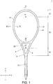
Fig. 1 is a front view showing a tennis racket frame according to an embodiment of the present invention. -
Fig. 2 is a right side view showing the tennis racket frame ofFig. 1 . -
Fig. 3 is an enlarged view showing a portion of the tennis racket frame ofFig. 1 . -
Fig. 4 is an enlarged cross-sectional view taken along line IV-IV ofFig. 1 . -
Fig. 5 is an enlarged cross-sectional view taken along line V-V ofFig. 1 . -
Fig. 6 is an enlarged cross-sectional view taken along line VI-VI ofFig. 1 . -
Fig. 7 is an enlarged cross-sectional view taken along line VII-VII ofFig. 3 . -
Fig. 8 is an enlarged cross-sectional view taken along line VIII-VIII ofFig. 3 . -
Fig. 9 is an enlarged view showing a portion of the tennis racket frame ofFig. 1 . - Hereinafter, the present invention will be described in detail on the basis of a preferred embodiment while referring to the accompanying drawings appropriately.
- In
Figs. 1 to 3 , aracket frame 2 used for tennis played with regulation balls is shown. Theracket frame 2 includes ahead 4, twothroats 6, ashaft 8 and agrip 10. A grommet, a grip tape, an end cap, and so on, are attached to theracket frame 2. Further, a string is stretched in theracket frame 2. InFig. 1 , a direction shown by an arrow X is a widthwise direction of theracket frame 2, and a direction shown by an arrow Y is an axial direction of theracket frame 2. InFig. 2 , a direction shown by an arrow Z is a thickness direction of theracket frame 2. In the racket obtained from theracket frame 2, a ball hitting surface is parallel to an X-Y plane. - The
racket frame 2 is formed of a pipe. In other words, theracket frame 2 is hollow. The pipe has anouter surface 12, aninner surface 14 and a pair of middle surfaces 16. A material of the pipe is a fiber-reinforced resin. A matrix resin of the fiber-reinforced resin is a thermoset resin. A typical thermoset resin is an epoxy resin. A typical fiber of the fiber-reinforced resin is a carbon fiber. The fiber is a long fiber. - The
head 4 forms a contour of a ball hitting surface. A front surface shape of thehead 4 is substantially an ellipse. A major-axis direction of the ellipse coincides with the axial direction Y of theracket frame 2. A minor-axis direction of the ellipse coincides with the widthwise direction X of theracket frame 2. Theouter surface 12 of thehead 4 has agut groove 18. As shown inFig. 2 , thegut groove 18 extends in a circumferential direction of thehead 4. The grommet (not shown) is fitted into thegut groove 18. - One end of each of the
throats 6 is connected to thehead 4. Thethroat 6 joins at theother throat 6 in the vicinity of the other ends. Thethroats 6 extend from thehead 4 to reach theshaft 8. Theshaft 8 extends from a place to which the twothroats 6 join. Theshaft 8 is formed continuously and integrally with thethroats 6. Thegrip 10 is formed continuously and integrally with theshaft 8. A portion of thehead 4 sandwiched between the twothroats 6 is ayoke 20. - As shown in
Fig. 1 , theracket frame 2 except for thegrip 10 can be divided into atop section 22, a grip-side section 24 and acentral section 26. Thecentral section 26 is disposed between thetop section 22 and the grip-side section 24. Thetop section 22 includes a portion of thehead 4. Thecentral section 26 includes a portion of thehead 4 and portions of thethroats 6. The grip-side section 24 includes portions of thethroats 6 and a portion of theshaft 8. -
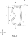
Fig. 4 is an enlarged cross-sectional view taken along line IV-IV ofFig. 1 . InFig. 4 , a portion of thehead 4 belonging to thecentral section 26 is shown. InFig. 4 , theouter surface 12, theinner surface 14 and the pair ofmiddle surfaces 16 are shown. The middle surfaces 16 are disposed between theouter surface 12 and theinner surface 14. Theouter surface 12 has thegut groove 18. - As shown in
Fig. 4 , a thickness Ti of theinner surface 14 is larger than a thickness To of theouter surface 12. The thickness of the pipe is gradually increased inward. Accordingly, themiddle surfaces 16 are inclined with respect to the X direction. In other words, themiddle surfaces 16 are inclined with respect to the ball hitting surface. In the present invention, a portion in which the thickness Ti of theinner surface 14 is larger than the thickness To of theouter surface 12 is referred to as an innerthick part 28. - The inner
thick part 28 is present mainly in thecentral section 26. Bending rigidity of the innerthick part 28 is low. When a ball is hit by the racket having the innerthick part 28, theracket frame 2 is sufficiently deformed. A long contact time between the racket and the ball can be achieved by the deformation. A player who uses the racket can strike a ball with a large ball launch angle. The large ball launch angle causes a high trajectory. The large ball launch angle further shifts a position of an apex of the trajectory to a position close to a baseline of an opponent. The trajectory enables a player to achieve an advantage in the game. Moreover, sufficient deformation of theracket frame 2 can also contribute to a soft feeling of hitting the ball. -
Fig. 5 is an enlarged cross-sectional view taken along line V-V ofFig. 1 . InFig. 5 , a portion of thehead 4 belonging to thetop section 22 is shown. InFig. 5 , theouter surface 12, theinner surface 14 and the pair ofmiddle surfaces 16 are shown. The middle surfaces 16 are disposed between theouter surface 12 and theinner surface 14. Theouter surface 12 has thegut groove 18. - As shown in
Fig. 5 , a thickness To of theouter surface 12 is larger than a thickness Ti of theinner surface 14. The thickness of the pipe is gradually increased outward. Accordingly, themiddle surfaces 16 are inclined with respect to the Y direction. In other words, themiddle surfaces 16 are inclined with respect to the ball hitting surface. In the present invention, a portion in which the thickness To of theouter surface 12 is larger than the thickness Ti of theinner surface 14 is referred to as an outerthick part 30. - The outer
thick part 30 is present mainly in thetop section 22. The outerthick part 30 has low bending rigidity when a low load is applied but high bending rigidity when a high load is applied. The outerthick part 30 can contribute to resilience when a stroke is at a high speed. The outerthick part 30 can also contribute to resilience when a ball is served. Further, the outerthick part 30 can also contribute to stability in an orientation of a face when hitting. - In the
racket frame 2, since thecentral section 26 mainly has the innerthick part 28 and thetop section 22 mainly has the outerthick part 30, a long contact time and resilience are compatible. - The
racket frame 2 may include thehead 4 that does not have the outerthick part 30. Even in this case, a long contact time which is an effect of the innerthick part 28 is achieved. -
Fig. 6 is an enlarged cross-sectional view taken along line VI-VI ofFig. 1 . InFig. 6 , theyoke 20 is shown. As will be apparent fromFig. 1 , theyoke 20 belongs to thecentral section 26. InFig. 6 , theouter surface 12, theinner surface 14 and the pair ofmiddle surfaces 16 are shown. The middle surfaces 16 are disposed between theouter surface 12 and theinner surface 14. Theouter surface 12 has thegut groove 18. - As shown in
Fig. 6 , a thickness Ti of theinner surface 14 is larger than a thickness To of theouter surface 12. The thickness of the pipe is gradually increased inward. Accordingly, themiddle surfaces 16 are inclined with respect to the Y direction. In other words, themiddle surfaces 16 are inclined with respect to the ball hitting surface. - A portion shown in
Fig. 6 is the innerthick part 28. Bending rigidity of the innerthick part 28 is low. When a ball is hit by the racket having the innerthick part 28, theracket frame 2 is sufficiently deformed. A long contact time between the racket and the ball can be achieved by the deformation. A player who uses the racket can hit a ball with a large ball launch angle. The large ball launch angle causes a high trajectory. The large ball launch angle further shifts a position of an apex of a trajectory to a position close to a baseline of an opponent. The trajectory enables a player to achieve an advantage in the game. Moreover, sufficient deformation of theracket frame 2 can also contribute to a soft feeling of hitting the ball. Thehead 4 may include theyoke 20 that does not have the innerthick part 28. -
Fig. 7 is an enlarged cross-sectional view taken along line VII-VII ofFig. 3 . InFig. 7 , a portion of thethroat 6 close to thehead 4 is shown. As will be apparent fromFigs. 1 and3 , a portion shown inFig. 7 belongs to thecentral section 26. InFig. 7 , theouter surface 12, theinner surface 14 and the pair ofmiddle surfaces 16 are shown. The middle surfaces 16 are disposed between theouter surface 12 and theinner surface 14. Theouter surface 12 does not have thegut groove 18. - As shown in
Fig. 7 , a thickness Ti of theinner surface 14 is larger than a thickness To of theouter surface 12. The thickness of the pipe is gradually increased inward. Accordingly, themiddle surfaces 16 are inclined with respect to a left/right direction ofFig. 7 . In other words, themiddle surfaces 16 are inclined with respect to the ball hitting surface. - A portion shown in
Fig. 7 is the innerthick part 28. Bending rigidity of the innerthick part 28 is low. When a ball is hit by the racket having the innerthick part 28, theracket frame 2 is sufficiently deformed. A long contact time between the racket and the ball can be achieved by the deformation. A player who uses the racket can hit a ball with a large ball launch angle. The large ball launch angle causes a high trajectory. The large ball launch angle further shifts a position of an apex of the trajectory to a position close to a baseline of an opponent. The trajectory enables a player to achieve an advantage in the game. Moreover, sufficient deformation of theracket frame 2 can also contribute to a soft feeling of hitting the ball. Thehead 4 may include thethroats 6 that do not have the innerthick part 28. -
Fig. 8 is an enlarged cross-sectional view taken along line VIII-VIII ofFig. 3 . InFig. 8 , a portion of thethroat 6 close to theshaft 8 is shown. As will be apparent fromFigs. 1 and3 , a portion shown inFig. 8 belongs to the grip-side section 24. InFig. 8 , theouter surface 12, theinner surface 14 and the pair ofmiddle surfaces 16 are shown. The middle surfaces 16 can be disposed between theouter surface 12 and theinner surface 14. Theouter surface 12 does not have thegut groove 18. - As shown in
Fig. 8 , a thickness Ti of theinner surface 14 is equal to a thickness To of theouter surface 12. Accordingly, themiddle surfaces 16 extend in the left/right direction ofFig. 8 . In other words, themiddle surfaces 16 are parallel to a ball hitting surface. In the present invention, a portion in which the thickness Ti of theinner surface 14 is equal to the thickness To of theouter surface 12 is referred to as auniform thickness part 32. Bending rigidity of theuniform thickness part 32 is high. Theuniform thickness part 32 contributes to resilience. Theuniform thickness part 32 can further contribute to stability in an orientation of the face. - The
racket frame 2 may include thehead 4 that does not have theuniform thickness part 32. Even in this case, a long contact time which is an effect of the innerthick part 28 can be achieved. -
Fig. 9 is an enlarged view showing a portion of thetennis racket frame 2 ofFig. 1 . InFig. 9 , a region hatched by leftward/upward lines is the outerthick part 30, a region hatched by rightward/upward lines is the innerthick part 28, and a region hatched by lateral lines is theuniform thickness part 32. A region disposed between the outerthick part 30 and the innerthick part 28 is afirst transition zone 34. A region between the innerthick part 28 and theuniform thickness part 32 is asecond transition zone 36. In thefirst transition zone 34, a cross-sectional shape thereof is gradually changed to the shape shown inFig. 4 from the shape shown inFig. 5 . In thesecond transition zone 36, a cross-sectional shape thereof is gradually changed to the shape shown inFig. 8 from the shape shown inFig. 7 . - In
Fig. 9 , an angle designated by reference sign θ1 is a central angle from a top-most vertex to a boundary between the outerthick part 30 and thefirst transition zone 34. From the viewpoint of resilience and stability of an orientation of a face, the angle θ1 is preferably 30° or more and, in particular, preferably 40° or more. From the viewpoint that the innerthick part 28 can be sufficiently increased, the angle θ1 is preferably 85° or less and, in particular, 75° or less. - An angle designated by reference sign θ2 in
Fig. 9 is a central angle from a top-most vertex to a boundary between thefirst transition zone 34 and the innerthick part 28. From the viewpoint of a long contact time with a ball, the angle θ2 is preferably 90° or less and, in particular, preferably 80° or less. From the viewpoint that the outerthick part 30 can be sufficiently increased, the angle θ2 is preferably 40° or more and, in particular, 50° or more. - A length represented by an arrow L2 in
Fig. 9 is a length of the innerthick part 28 in thethroat 6. The length L2 is measured in the axial direction. From the viewpoint of a long contact time with a ball, a ratio (L2/L1) of the length L2 with respect to a length L1 of thethroat 6 is preferably 0.2 or more and, in particular, preferably 0.3 or more. From the viewpoint that theuniform thickness part 32 can be sufficiently increased, the ratio (L2/L1) is preferably 0.7 or less and, in particular, preferably 0.6 or less. - A length represented by an arrow L3 in
Fig. 9 is a length of theuniform thickness part 32 in thethroat 6. The length L3 is measured in the axial direction. From the viewpoint of resilience and stability of an orientation of a face, a ratio (L3/L1) of the length L3 with respect to the length L1 of thethroat 6 is preferably 0.2 or more and, in particular, preferably 0.3 or more. From the viewpoint that the innerthick part 28 can be sufficiently increased, the ratio (L3/L1) is preferably 0.7 or less and, in particular, preferably 0.6 or less. - A distance represented by an arrow Ld in
Figs. 4 to 7 is a distance between the outer end and the inner end of themiddle surfaces 16 in a thickness direction. From the viewpoint of balance of various performances, the distance Ld is preferably 0.5 mm or more and, in particular, preferably 0.8 mm or more. From the viewpoint of balance of various performances, the distance Ld is preferably 3.0 mm or less and, in particular, preferably 2.0 mm or less. - In each area of the racket frame, the larger thickness among the thickness Ti of the
inner surface 14 and the thickness To of theouter surface 12 is preferably 20 mm or more and 30 mm or less and, in particular, preferably 22 mm or more and 26 mm or less. - An angle designated by reference sign θd in
Figs. 4 to 7 is an inclined angle of the middle surfaces 16. From the viewpoint of balance of various performances, the angle θd is preferably 3° or more and, in particular, preferably 5° or more. From the viewpoint of balance of various performances, the angle θd is preferably 30° or less and, in particular, preferably 20° or less. - In the
racket frame 2 according to the present invention, the distribution of rigidity can be adjusted by devising the cross-sectional shape. Accordingly, there is no need to use a specific material (prepreg) in adjustment of the distribution of rigidity. In the racket frame, the distribution of rigidity can be adjusted conveniently at low cost. Of course, a specific material may be used in theracket frame 2. - Various modifications may be made in the cross-sectional shape of the racket frame. Since the inner thick part is present at any position in the racket frame and the outer thick part is present at the other position, a long contact time and resilience are compatible.
- When the top section has the inner thick part, the central section preferably has an outer thick part or a uniform thickness part. When the top section has the outer thick part, the central section preferably has the inner thick part or the uniform thickness part. When the top section has a uniform thickness part, the central section preferably has the inner thick part or the outer thick part.
- When the central section has the inner thick part, the grip-side section preferably has the outer thick part or the uniform thickness part. When the central section has the outer thick part, the grip-side section preferably has the inner thick part or the uniform thickness part. When the central section has the uniform thickness part, the grip-side section preferably has the inner thick part or the outer thick part.
- Hereinafter, while the effects of the present invention are clarified by an example, the present invention should not be interpreted restrictively on the basis of the description of the example.
- The racket frame shown in
Figs. 1 to 9 was formed. A thickness of the racket frame is as follows. -
- Thickness To of outer surface: 22 mm
- Thickness Ti of inner surface: 20 mm
-
- Thickness To of outer surface: 20 mm
- Thickness Ti of inner surface: 22 mm
-
- Thickness To of outer surface: 21 mm
- Thickness Ti of inner surface: 21 mm
- A commercially available racket frame was prepared. A thickness of the racket frame is as follows.
-
- Thickness To of outer surface: 21 mm
- Thickness Ti of inner surface: 21 mm
-
- Thickness To of outer surface: 21 mm
- Thickness Ti of inner surface: 21 mm
-
- Thickness To of outer surface: 21 mm
- Thickness Ti of inner surface: 21 mm
- A grommet, a string, and so on, were attached to the racket frame to obtain a racket. A rally was performed by players with the rackets. The trajectory was tracked and measured, and an average value of an average value of a ball launch angle of a ball and a horizontal distance from a stroke point to an apex of the trajectory was calculated. A result thereof is shown in the following Table 1.
- Services were performed by players using the rackets and speeds of balls were measured. Averages of the results obtained by multiple measurements are represented in the following Table 1.
-
Table 1 Estimated Results Example Comparative Example Player A Launch angle (degree) 3.36 2.61 Distance to apex (m) 7.19 6.74 Speed of service (km/h) 156.3 154.7 Player B Launch angle (degree) 3.99 3.70 Distance to apex (m) 8.01 7.33 Speed of service (km/h) 167.7 161.6 - As shown in Table 1, the racket of the example is superior in performance. From the evaluation results, the superiority of the present invention is obvious.
- The racket according to the present invention is suitable for professional players participating in tours and is also suitable for amateur players.
Claims (9)
- A tennis racket frame formed of a pipe having an outer surface, an inner surface, and a pair of middle surfaces each disposed between the outer surface and the inner surface, the tennis racket frame comprising:(1) an inner thick part in which the middle surfaces are inclined with respect to a ball hitting surface such that a thickness of the pipe is gradually increased inward; and(2) an outer thick part in which the middle surfaces are inclined with respect to the ball hitting surface such that the thickness of the pipe is gradually increased outward.
- The tennis racket frame according to claim 1, further comprising:(3) a uniform thickness part in which the middle surfaces are parallel to the ball hitting surface.
- The tennis racket frame according to claim 2, wherein, when the tennis racket frame is divided into a top section, a grip-side section, and a central section disposed between the top section and the grip-side section,
the top section has any of the inner thick part, the outer thick part and the uniform thickness part, and
the central section has the remainder of the inner thick part, the outer thick part and the uniform thickness part. - The tennis racket frame according to claim 2, wherein, when the tennis racket frame is divided into a top section, a grip-side section, and a central section disposed between the top section and the grip-side section,
the central section has any of the inner thick part, the outer thick part and the uniform thickness part, and
the grip-side section has the remainder of the inner thick part, the outer thick part and the uniform thickness part. - The tennis racket frame according to any one of claims 1 to 4, wherein a distance between an outer end and an inner end of the middle surface of the inner thick part in a thickness direction is 0.5 mm or more.
- The tennis racket frame according to any one of claims 1 to 5, wherein a distance between an inner end and an outer end of the middle surface of the outer thick part in a thickness direction is 0.5 mm or more.
- A tennis racket frame formed of a pipe having an outer surface, an inner surface, and a pair of middle surfaces each disposed between the outer surface and the inner surface, wherein the tennis racket frame is divided into a top section, a grip-side section, and a central section disposed between the top section and the grip-side section, the central section has an inner thick part, and
in the inner thick part, the middle surfaces are inclined with respect to a ball hitting surface such that a thickness of the pipe is gradually increased inward. - The tennis racket frame according to claim 7, wherein the top section has an outer thick part, and in the outer thick part, the middle surfaces are inclined with respect to the ball hitting surface such that a thickness of the pipe is gradually increased outward.
- The tennis racket frame according to claim 7 or 8, wherein the grip-side section has a uniform thickness part, and in the uniform thickness part, the middle surfaces are parallel to the ball hitting surface.
Applications Claiming Priority (1)
| Application Number | Priority Date | Filing Date | Title |
|---|---|---|---|
| JP2016250397A JP6776883B2 (en) | 2016-12-26 | 2016-12-26 | Tennis racket frame |
Publications (2)
| Publication Number | Publication Date |
|---|---|
| EP3338865A1 true EP3338865A1 (en) | 2018-06-27 |
| EP3338865B1 EP3338865B1 (en) | 2020-01-08 |
Family
ID=60269723
Family Applications (1)
| Application Number | Title | Priority Date | Filing Date |
|---|---|---|---|
| EP17200426.9A Active EP3338865B1 (en) | 2016-12-26 | 2017-11-07 | Tennis racket frame |
Country Status (6)
| Country | Link |
|---|---|
| US (1) | US10245473B2 (en) |
| EP (1) | EP3338865B1 (en) |
| JP (1) | JP6776883B2 (en) |
| KR (1) | KR102385475B1 (en) |
| CN (1) | CN108236778B (en) |
| TW (1) | TWI724251B (en) |
Cited By (1)
| Publication number | Priority date | Publication date | Assignee | Title |
|---|---|---|---|---|
| JP2018102454A (en) * | 2016-12-26 | 2018-07-05 | 住友ゴム工業株式会社 | Tennis racket frame |
Families Citing this family (4)
| Publication number | Priority date | Publication date | Assignee | Title |
|---|---|---|---|---|
| USD877833S1 (en) * | 2017-12-28 | 2020-03-10 | Sumitomo Rubber Industries, Ltd. | Tennis racket frame |
| KR102335859B1 (en) | 2020-08-13 | 2021-12-06 | 경북대학교 산학협력단 | customized wireless remote controller |
| TWI843600B (en) * | 2023-06-14 | 2024-05-21 | 薩摩亞商順譽世界企業有限公司 | Pipe fittings and tennis rackets |
| WO2025234266A1 (en) * | 2024-05-08 | 2025-11-13 | ヨネックス株式会社 | Racket |
Citations (6)
| Publication number | Priority date | Publication date | Assignee | Title |
|---|---|---|---|---|
| JPH08168540A (en) * | 1994-12-19 | 1996-07-02 | Bridgestone Sports Co Ltd | racket |
| JPH09299517A (en) * | 1996-05-14 | 1997-11-25 | Bridgestone Sports Co Ltd | Racket frame |
| JPH1028746A (en) * | 1996-05-14 | 1998-02-03 | Bridgestone Sports Co Ltd | Racket frame |
| JP2003093548A (en) * | 2001-09-26 | 2003-04-02 | Sumitomo Rubber Ind Ltd | Racket frame |
| JP2015016152A (en) * | 2013-07-11 | 2015-01-29 | 岡本 幸士 | Racket frame |
| JP2015150028A (en) | 2014-02-12 | 2015-08-24 | ダンロップスポーツ株式会社 | racket |
Family Cites Families (22)
| Publication number | Priority date | Publication date | Assignee | Title |
|---|---|---|---|---|
| EP0104930B1 (en) * | 1982-09-27 | 1989-04-26 | Tsai Chen Soong | Frame for sports racket |
| US5014987A (en) * | 1982-09-27 | 1991-05-14 | Soong Tsai C | Frame for sports racket |
| IN170468B (en) * | 1987-08-04 | 1992-03-28 | Wilson Sporting Goods | |
| JPH0429621Y2 (en) * | 1988-01-23 | 1992-07-17 | ||
| FR2649899B1 (en) * | 1989-07-19 | 1992-05-22 | Rossignol Sa | TENNIS RACKET |
| US5071124A (en) * | 1990-05-03 | 1991-12-10 | Prince Manufacturing, Inc | Badminton racquet |
| US5540434A (en) * | 1990-08-21 | 1996-07-30 | Wilson Sporting Goods Co. | Tennis racket |
| DE4037568A1 (en) * | 1990-11-26 | 1992-05-27 | Donnay Int Sa | TENNIS RACKET |
| FR2673381B1 (en) * | 1991-02-28 | 1994-05-06 | Rossignol Sa Skis | RACKET WITH LONGITUDINAL ASYMMETRY. |
| US5299801A (en) * | 1991-05-23 | 1994-04-05 | Donnay International S.A. | Tennis racket |
| JP2508947B2 (en) * | 1991-07-29 | 1996-06-19 | ヤマハ株式会社 | Racket frame for tennis |
| CN2153391Y (en) * | 1993-02-19 | 1994-01-19 | 刘继志 | racket |
| US6383099B1 (en) * | 1995-05-22 | 2002-05-07 | Wilson Sporting Goods Co. | Tennis racquet |
| JPH09108385A (en) * | 1995-10-19 | 1997-04-28 | Yamaha Corp | Racket frame |
| JP2996911B2 (en) * | 1996-03-12 | 2000-01-11 | 住友ゴム工業株式会社 | Racket frame manufacturing method |
| US5810683A (en) * | 1996-12-23 | 1998-09-22 | Prince Sports Group, Inc. | Morph frame for sports racquet |
| DE60015526T2 (en) * | 2000-08-01 | 2005-05-12 | Head Technology Gmbh | Racket for ball game and manufacturing process for it |
| CN2548664Y (en) * | 2002-06-13 | 2003-05-07 | 厦门侨兴工业有限公司 | Racket with sectional structure improvement |
| JP5349183B2 (en) * | 2009-07-21 | 2013-11-20 | ブリヂストンスポーツ株式会社 | Racket frame |
| JP6196786B2 (en) * | 2013-03-06 | 2017-09-13 | ヨネックス株式会社 | racket |
| CN105031894B (en) * | 2015-09-02 | 2018-06-19 | 陈正盛 | Racket and manufacturing method thereof |
| JP6776883B2 (en) * | 2016-12-26 | 2020-10-28 | 住友ゴム工業株式会社 | Tennis racket frame |
-
2016
- 2016-12-26 JP JP2016250397A patent/JP6776883B2/en active Active
-
2017
- 2017-09-14 KR KR1020170117651A patent/KR102385475B1/en active Active
- 2017-11-06 CN CN201711081234.3A patent/CN108236778B/en active Active
- 2017-11-07 EP EP17200426.9A patent/EP3338865B1/en active Active
- 2017-11-07 TW TW106138489A patent/TWI724251B/en active
- 2017-11-09 US US15/807,576 patent/US10245473B2/en active Active
Patent Citations (6)
| Publication number | Priority date | Publication date | Assignee | Title |
|---|---|---|---|---|
| JPH08168540A (en) * | 1994-12-19 | 1996-07-02 | Bridgestone Sports Co Ltd | racket |
| JPH09299517A (en) * | 1996-05-14 | 1997-11-25 | Bridgestone Sports Co Ltd | Racket frame |
| JPH1028746A (en) * | 1996-05-14 | 1998-02-03 | Bridgestone Sports Co Ltd | Racket frame |
| JP2003093548A (en) * | 2001-09-26 | 2003-04-02 | Sumitomo Rubber Ind Ltd | Racket frame |
| JP2015016152A (en) * | 2013-07-11 | 2015-01-29 | 岡本 幸士 | Racket frame |
| JP2015150028A (en) | 2014-02-12 | 2015-08-24 | ダンロップスポーツ株式会社 | racket |
Cited By (1)
| Publication number | Priority date | Publication date | Assignee | Title |
|---|---|---|---|---|
| JP2018102454A (en) * | 2016-12-26 | 2018-07-05 | 住友ゴム工業株式会社 | Tennis racket frame |
Also Published As
| Publication number | Publication date |
|---|---|
| CN108236778B (en) | 2021-03-16 |
| US20180178085A1 (en) | 2018-06-28 |
| JP2018102454A (en) | 2018-07-05 |
| US10245473B2 (en) | 2019-04-02 |
| CN108236778A (en) | 2018-07-03 |
| TW201822847A (en) | 2018-07-01 |
| TWI724251B (en) | 2021-04-11 |
| EP3338865B1 (en) | 2020-01-08 |
| KR20180075366A (en) | 2018-07-04 |
| JP6776883B2 (en) | 2020-10-28 |
| KR102385475B1 (en) | 2022-04-11 |
Similar Documents
| Publication | Publication Date | Title |
|---|---|---|
| EP3338865B1 (en) | Tennis racket frame | |
| JP6450786B2 (en) | Golf club head with body features that affect impact | |
| US11161016B2 (en) | Racket | |
| US10065082B2 (en) | Golf club | |
| JP2008005994A (en) | Iron type golf club head | |
| US10561907B2 (en) | Racket frame | |
| US20230141640A1 (en) | Racket | |
| US9393467B2 (en) | Iron type golf club head | |
| US20150352411A1 (en) | Racket | |
| JP3540195B2 (en) | Fiber reinforced plastic golf club shaft | |
| US12076620B2 (en) | Grommet and racket | |
| JP6770600B2 (en) | Iron golf club head | |
| EP2762205A1 (en) | Racket frame | |
| JP4800741B2 (en) | Golf club shaft | |
| JP4253072B2 (en) | racket | |
| JP2002306639A (en) | racket | |
| JP3078194U (en) | Golf club shaft | |
| US20240335707A1 (en) | Golf club head with a variable internal edge radius | |
| KR101437005B1 (en) | Mortar shaped golf shaft and golf club having the same | |
| JP4079641B2 (en) | Golf club shaft | |
| WO2025234266A1 (en) | Racket | |
| JPH075658U (en) | Golf club set | |
| JP2000342729A (en) | Golf club shaft |
Legal Events
| Date | Code | Title | Description |
|---|---|---|---|
| PUAI | Public reference made under article 153(3) epc to a published international application that has entered the european phase |
Free format text: ORIGINAL CODE: 0009012 |
|
| STAA | Information on the status of an ep patent application or granted ep patent |
Free format text: STATUS: THE APPLICATION HAS BEEN PUBLISHED |
|
| AK | Designated contracting states |
Kind code of ref document: A1 Designated state(s): AL AT BE BG CH CY CZ DE DK EE ES FI FR GB GR HR HU IE IS IT LI LT LU LV MC MK MT NL NO PL PT RO RS SE SI SK SM TR |
|
| AX | Request for extension of the european patent |
Extension state: BA ME |
|
| STAA | Information on the status of an ep patent application or granted ep patent |
Free format text: STATUS: REQUEST FOR EXAMINATION WAS MADE |
|
| 17P | Request for examination filed |
Effective date: 20181219 |
|
| RBV | Designated contracting states (corrected) |
Designated state(s): AL AT BE BG CH CY CZ DE DK EE ES FI FR GB GR HR HU IE IS IT LI LT LU LV MC MK MT NL NO PL PT RO RS SE SI SK SM TR |
|
| GRAP | Despatch of communication of intention to grant a patent |
Free format text: ORIGINAL CODE: EPIDOSNIGR1 |
|
| STAA | Information on the status of an ep patent application or granted ep patent |
Free format text: STATUS: GRANT OF PATENT IS INTENDED |
|
| INTG | Intention to grant announced |
Effective date: 20190619 |
|
| GRAS | Grant fee paid |
Free format text: ORIGINAL CODE: EPIDOSNIGR3 |
|
| GRAA | (expected) grant |
Free format text: ORIGINAL CODE: 0009210 |
|
| STAA | Information on the status of an ep patent application or granted ep patent |
Free format text: STATUS: THE PATENT HAS BEEN GRANTED |
|
| AK | Designated contracting states |
Kind code of ref document: B1 Designated state(s): AL AT BE BG CH CY CZ DE DK EE ES FI FR GB GR HR HU IE IS IT LI LT LU LV MC MK MT NL NO PL PT RO RS SE SI SK SM TR |
|
| REG | Reference to a national code |
Ref country code: GB Ref legal event code: FG4D |
|
| REG | Reference to a national code |
Ref country code: CH Ref legal event code: EP |
|
| REG | Reference to a national code |
Ref country code: DE Ref legal event code: R096 Ref document number: 602017010624 Country of ref document: DE |
|
| REG | Reference to a national code |
Ref country code: IE Ref legal event code: FG4D |
|
| REG | Reference to a national code |
Ref country code: AT Ref legal event code: REF Ref document number: 1221968 Country of ref document: AT Kind code of ref document: T Effective date: 20200215 |
|
| REG | Reference to a national code |
Ref country code: NL Ref legal event code: MP Effective date: 20200108 |
|
| REG | Reference to a national code |
Ref country code: LT Ref legal event code: MG4D |
|
| PG25 | Lapsed in a contracting state [announced via postgrant information from national office to epo] |
Ref country code: NL Free format text: LAPSE BECAUSE OF FAILURE TO SUBMIT A TRANSLATION OF THE DESCRIPTION OR TO PAY THE FEE WITHIN THE PRESCRIBED TIME-LIMIT Effective date: 20200108 Ref country code: LT Free format text: LAPSE BECAUSE OF FAILURE TO SUBMIT A TRANSLATION OF THE DESCRIPTION OR TO PAY THE FEE WITHIN THE PRESCRIBED TIME-LIMIT Effective date: 20200108 Ref country code: NO Free format text: LAPSE BECAUSE OF FAILURE TO SUBMIT A TRANSLATION OF THE DESCRIPTION OR TO PAY THE FEE WITHIN THE PRESCRIBED TIME-LIMIT Effective date: 20200408 Ref country code: PT Free format text: LAPSE BECAUSE OF FAILURE TO SUBMIT A TRANSLATION OF THE DESCRIPTION OR TO PAY THE FEE WITHIN THE PRESCRIBED TIME-LIMIT Effective date: 20200531 Ref country code: RS Free format text: LAPSE BECAUSE OF FAILURE TO SUBMIT A TRANSLATION OF THE DESCRIPTION OR TO PAY THE FEE WITHIN THE PRESCRIBED TIME-LIMIT Effective date: 20200108 Ref country code: FI Free format text: LAPSE BECAUSE OF FAILURE TO SUBMIT A TRANSLATION OF THE DESCRIPTION OR TO PAY THE FEE WITHIN THE PRESCRIBED TIME-LIMIT Effective date: 20200108 |
|
| PG25 | Lapsed in a contracting state [announced via postgrant information from national office to epo] |
Ref country code: SE Free format text: LAPSE BECAUSE OF FAILURE TO SUBMIT A TRANSLATION OF THE DESCRIPTION OR TO PAY THE FEE WITHIN THE PRESCRIBED TIME-LIMIT Effective date: 20200108 Ref country code: LV Free format text: LAPSE BECAUSE OF FAILURE TO SUBMIT A TRANSLATION OF THE DESCRIPTION OR TO PAY THE FEE WITHIN THE PRESCRIBED TIME-LIMIT Effective date: 20200108 Ref country code: HR Free format text: LAPSE BECAUSE OF FAILURE TO SUBMIT A TRANSLATION OF THE DESCRIPTION OR TO PAY THE FEE WITHIN THE PRESCRIBED TIME-LIMIT Effective date: 20200108 Ref country code: BG Free format text: LAPSE BECAUSE OF FAILURE TO SUBMIT A TRANSLATION OF THE DESCRIPTION OR TO PAY THE FEE WITHIN THE PRESCRIBED TIME-LIMIT Effective date: 20200408 Ref country code: IS Free format text: LAPSE BECAUSE OF FAILURE TO SUBMIT A TRANSLATION OF THE DESCRIPTION OR TO PAY THE FEE WITHIN THE PRESCRIBED TIME-LIMIT Effective date: 20200508 Ref country code: GR Free format text: LAPSE BECAUSE OF FAILURE TO SUBMIT A TRANSLATION OF THE DESCRIPTION OR TO PAY THE FEE WITHIN THE PRESCRIBED TIME-LIMIT Effective date: 20200409 |
|
| REG | Reference to a national code |
Ref country code: DE Ref legal event code: R097 Ref document number: 602017010624 Country of ref document: DE |
|
| PG25 | Lapsed in a contracting state [announced via postgrant information from national office to epo] |
Ref country code: SM Free format text: LAPSE BECAUSE OF FAILURE TO SUBMIT A TRANSLATION OF THE DESCRIPTION OR TO PAY THE FEE WITHIN THE PRESCRIBED TIME-LIMIT Effective date: 20200108 Ref country code: EE Free format text: LAPSE BECAUSE OF FAILURE TO SUBMIT A TRANSLATION OF THE DESCRIPTION OR TO PAY THE FEE WITHIN THE PRESCRIBED TIME-LIMIT Effective date: 20200108 Ref country code: CZ Free format text: LAPSE BECAUSE OF FAILURE TO SUBMIT A TRANSLATION OF THE DESCRIPTION OR TO PAY THE FEE WITHIN THE PRESCRIBED TIME-LIMIT Effective date: 20200108 Ref country code: RO Free format text: LAPSE BECAUSE OF FAILURE TO SUBMIT A TRANSLATION OF THE DESCRIPTION OR TO PAY THE FEE WITHIN THE PRESCRIBED TIME-LIMIT Effective date: 20200108 Ref country code: ES Free format text: LAPSE BECAUSE OF FAILURE TO SUBMIT A TRANSLATION OF THE DESCRIPTION OR TO PAY THE FEE WITHIN THE PRESCRIBED TIME-LIMIT Effective date: 20200108 Ref country code: DK Free format text: LAPSE BECAUSE OF FAILURE TO SUBMIT A TRANSLATION OF THE DESCRIPTION OR TO PAY THE FEE WITHIN THE PRESCRIBED TIME-LIMIT Effective date: 20200108 Ref country code: SK Free format text: LAPSE BECAUSE OF FAILURE TO SUBMIT A TRANSLATION OF THE DESCRIPTION OR TO PAY THE FEE WITHIN THE PRESCRIBED TIME-LIMIT Effective date: 20200108 |
|
| PLBE | No opposition filed within time limit |
Free format text: ORIGINAL CODE: 0009261 |
|
| STAA | Information on the status of an ep patent application or granted ep patent |
Free format text: STATUS: NO OPPOSITION FILED WITHIN TIME LIMIT |
|
| REG | Reference to a national code |
Ref country code: AT Ref legal event code: MK05 Ref document number: 1221968 Country of ref document: AT Kind code of ref document: T Effective date: 20200108 |
|
| 26N | No opposition filed |
Effective date: 20201009 |
|
| PG25 | Lapsed in a contracting state [announced via postgrant information from national office to epo] |
Ref country code: AT Free format text: LAPSE BECAUSE OF FAILURE TO SUBMIT A TRANSLATION OF THE DESCRIPTION OR TO PAY THE FEE WITHIN THE PRESCRIBED TIME-LIMIT Effective date: 20200108 Ref country code: IT Free format text: LAPSE BECAUSE OF FAILURE TO SUBMIT A TRANSLATION OF THE DESCRIPTION OR TO PAY THE FEE WITHIN THE PRESCRIBED TIME-LIMIT Effective date: 20200108 |
|
| PG25 | Lapsed in a contracting state [announced via postgrant information from national office to epo] |
Ref country code: PL Free format text: LAPSE BECAUSE OF FAILURE TO SUBMIT A TRANSLATION OF THE DESCRIPTION OR TO PAY THE FEE WITHIN THE PRESCRIBED TIME-LIMIT Effective date: 20200108 Ref country code: SI Free format text: LAPSE BECAUSE OF FAILURE TO SUBMIT A TRANSLATION OF THE DESCRIPTION OR TO PAY THE FEE WITHIN THE PRESCRIBED TIME-LIMIT Effective date: 20200108 |
|
| PG25 | Lapsed in a contracting state [announced via postgrant information from national office to epo] |
Ref country code: MC Free format text: LAPSE BECAUSE OF FAILURE TO SUBMIT A TRANSLATION OF THE DESCRIPTION OR TO PAY THE FEE WITHIN THE PRESCRIBED TIME-LIMIT Effective date: 20200108 |
|
| REG | Reference to a national code |
Ref country code: CH Ref legal event code: PL |
|
| PG25 | Lapsed in a contracting state [announced via postgrant information from national office to epo] |
Ref country code: LU Free format text: LAPSE BECAUSE OF NON-PAYMENT OF DUE FEES Effective date: 20201107 |
|
| REG | Reference to a national code |
Ref country code: BE Ref legal event code: MM Effective date: 20201130 |
|
| PG25 | Lapsed in a contracting state [announced via postgrant information from national office to epo] |
Ref country code: CH Free format text: LAPSE BECAUSE OF NON-PAYMENT OF DUE FEES Effective date: 20201130 Ref country code: LI Free format text: LAPSE BECAUSE OF NON-PAYMENT OF DUE FEES Effective date: 20201130 |
|
| PG25 | Lapsed in a contracting state [announced via postgrant information from national office to epo] |
Ref country code: IE Free format text: LAPSE BECAUSE OF NON-PAYMENT OF DUE FEES Effective date: 20201107 |
|
| PG25 | Lapsed in a contracting state [announced via postgrant information from national office to epo] |
Ref country code: TR Free format text: LAPSE BECAUSE OF FAILURE TO SUBMIT A TRANSLATION OF THE DESCRIPTION OR TO PAY THE FEE WITHIN THE PRESCRIBED TIME-LIMIT Effective date: 20200108 Ref country code: MT Free format text: LAPSE BECAUSE OF FAILURE TO SUBMIT A TRANSLATION OF THE DESCRIPTION OR TO PAY THE FEE WITHIN THE PRESCRIBED TIME-LIMIT Effective date: 20200108 Ref country code: CY Free format text: LAPSE BECAUSE OF FAILURE TO SUBMIT A TRANSLATION OF THE DESCRIPTION OR TO PAY THE FEE WITHIN THE PRESCRIBED TIME-LIMIT Effective date: 20200108 |
|
| PG25 | Lapsed in a contracting state [announced via postgrant information from national office to epo] |
Ref country code: MK Free format text: LAPSE BECAUSE OF FAILURE TO SUBMIT A TRANSLATION OF THE DESCRIPTION OR TO PAY THE FEE WITHIN THE PRESCRIBED TIME-LIMIT Effective date: 20200108 Ref country code: AL Free format text: LAPSE BECAUSE OF FAILURE TO SUBMIT A TRANSLATION OF THE DESCRIPTION OR TO PAY THE FEE WITHIN THE PRESCRIBED TIME-LIMIT Effective date: 20200108 |
|
| PG25 | Lapsed in a contracting state [announced via postgrant information from national office to epo] |
Ref country code: BE Free format text: LAPSE BECAUSE OF NON-PAYMENT OF DUE FEES Effective date: 20201130 |
|
| P01 | Opt-out of the competence of the unified patent court (upc) registered |
Effective date: 20230510 |
|
| PGFP | Annual fee paid to national office [announced via postgrant information from national office to epo] |
Ref country code: FR Payment date: 20250930 Year of fee payment: 9 |
|
| PGFP | Annual fee paid to national office [announced via postgrant information from national office to epo] |
Ref country code: DE Payment date: 20250930 Year of fee payment: 9 |
|
| PGFP | Annual fee paid to national office [announced via postgrant information from national office to epo] |
Ref country code: GB Payment date: 20251001 Year of fee payment: 9 |