EP3338445B1 - Fotografievorrichtung und verfahren zur steuerung davon - Google Patents
Fotografievorrichtung und verfahren zur steuerung davon Download PDFInfo
- Publication number
- EP3338445B1 EP3338445B1 EP16837204.3A EP16837204A EP3338445B1 EP 3338445 B1 EP3338445 B1 EP 3338445B1 EP 16837204 A EP16837204 A EP 16837204A EP 3338445 B1 EP3338445 B1 EP 3338445B1
- Authority
- EP
- European Patent Office
- Prior art keywords
- image
- buffer
- display
- photographing
- information
- Prior art date
- Legal status (The legal status is an assumption and is not a legal conclusion. Google has not performed a legal analysis and makes no representation as to the accuracy of the status listed.)
- Active
Links
Images


Classifications
-
- H—ELECTRICITY
- H04—ELECTRIC COMMUNICATION TECHNIQUE
- H04N—PICTORIAL COMMUNICATION, e.g. TELEVISION
- H04N23/00—Cameras or camera modules comprising electronic image sensors; Control thereof
- H04N23/45—Cameras or camera modules comprising electronic image sensors; Control thereof for generating image signals from two or more image sensors being of different type or operating in different modes, e.g. with a CMOS sensor for moving images in combination with a charge-coupled device [CCD] for still images
-
- H—ELECTRICITY
- H04—ELECTRIC COMMUNICATION TECHNIQUE
- H04N—PICTORIAL COMMUNICATION, e.g. TELEVISION
- H04N23/00—Cameras or camera modules comprising electronic image sensors; Control thereof
- H04N23/60—Control of cameras or camera modules
- H04N23/63—Control of cameras or camera modules by using electronic viewfinders
- H04N23/633—Control of cameras or camera modules by using electronic viewfinders for displaying additional information relating to control or operation of the camera
-
- H—ELECTRICITY
- H04—ELECTRIC COMMUNICATION TECHNIQUE
- H04N—PICTORIAL COMMUNICATION, e.g. TELEVISION
- H04N23/00—Cameras or camera modules comprising electronic image sensors; Control thereof
- H04N23/57—Mechanical or electrical details of cameras or camera modules specially adapted for being embedded in other devices
-
- H—ELECTRICITY
- H04—ELECTRIC COMMUNICATION TECHNIQUE
- H04N—PICTORIAL COMMUNICATION, e.g. TELEVISION
- H04N23/00—Cameras or camera modules comprising electronic image sensors; Control thereof
- H04N23/60—Control of cameras or camera modules
- H04N23/67—Focus control based on electronic image sensor signals
- H04N23/672—Focus control based on electronic image sensor signals based on the phase difference signals
-
- H—ELECTRICITY
- H04—ELECTRIC COMMUNICATION TECHNIQUE
- H04N—PICTORIAL COMMUNICATION, e.g. TELEVISION
- H04N23/00—Cameras or camera modules comprising electronic image sensors; Control thereof
- H04N23/60—Control of cameras or camera modules
- H04N23/67—Focus control based on electronic image sensor signals
- H04N23/673—Focus control based on electronic image sensor signals based on contrast or high frequency components of image signals, e.g. hill climbing method
Definitions
- the disclosure relates generally to a photographing apparatus and a method for controlling the same, and for example, to a photographing apparatus having a plurality of camera modules and a method for controlling the same.
- a camera mounted on a portable terminal apparatus such as, a smart phone, a tablet Personal Computer (PC), etc.
- a portable terminal apparatus such as, a smart phone, a tablet Personal Computer (PC), etc.
- PC Personal Computer
- a size of a camera module mounted on the portable terminal device is being miniaturized to correspond to the size of the portable terminal apparatus.
- a camera sensor needs to be increased.
- the size of the camera module mounted on the portable terminal apparatus has been miniaturized, there is a limit in enhancing the image quality of the camera.
- a multi-camera In order to resolve such problems, technologies for mounting a multi-camera on a portable terminal apparatus, such as, a smart phone, have been developing.
- the multi-camera When the multi-camera is mounted on the portable terminal apparatus, it is possible for the apparatus to provide diverse image services.
- the multi-camera occupies a broader area than the conventional single camera, and thus, a foreign substance, such as, a user finger, may be easily exposed to a lens of the multi-camera. Accordingly, a user may do not perform a desired image photographing operation.
- US 2011/0187886 A1 is related to an image pickup control unit displays either one of a picked-up image by a first image pickup unit and a picked-up image by a second image pickup unit on a display unit as a finder image.
- a feature detecting unit calculates a distribution of brightness values or brightness dispersion for each of the picked-up images by the first and second image pickup units, thereby detecting features of the two picked-up images.
- a sameness determining unit determines the sameness between both picked-up images based on the detected features, and determines that an abnormality like the unexpected appearance of an obstacle is present when the feature largely differs.
- a warning processing unit simultaneously displays both picked-up images on the display unit, or displays the picked-up image including the abnormality on the display unit as a finder image.
- US 2011/080494 A1 discloses an imaging apparatus including a camera module, a foreign object detection unit and a warning unit to notifying a user that a foreign object adheres to the optical lens.
- the warning message consists of displaying a warning indicating that a foreign object adheres to the optical lens or lighting up a warning lamp or outputting a warning tone.
- US 2013/128072 A1 discloses an image pickup device including two camera modules situated on the same side of the device which detects, from a comparison between image information extracted from the preview images captured by the two camera modules, if one of the two camera modules is obstructed by a foreign object (e.g a finger). If a camera module is obstructed a warning information is displayed.
- a foreign object e.g a finger
- the disclosure has been provided to address the aforementioned and other problems and disadvantages occurring in the related art, and an aspect of the disclosure provides a photographing apparatus which notifies a user of a state in which a foreign substance appears on at least one of a plurality of camera modules more intuitionally.
- an aspect of the disclosure provides a photographing apparatus which photographs an image or generates a composite image when a foreign substance does not exist on a plurality of camera modules.
- a photographing apparatus comprising features defined in the appended independent apparatus claim.
- a method for controlling a photographing apparatus with a plurality of camera modules comprising the steps defined in the appended independent method claim.
- the photographing apparatus may notify a user of the state more intuitionally.
- a term including an ordinal such as, 'first,' 'second,' etc., may be used to distinguish elements.
- the ordinal is used to distinguish the same or similar elements and does not limit the meaning of the term. For instance, ordinals do not affect an order of use or an order of arrangement of elements expressed with the ordinals. Respective ordinals may be replaced with each other, if necessary.
- the terms 'module,' 'unit,' and 'part' may refer to an element which performs at least one function or operation.
- the element may be realized as hardware (e.g., circuitry), software, or combination thereof.
- a plurality of 'modules,' 'units,' and 'parts' may be integrated into at least one module or chip such that it is realized as at least one processor (not shown) except for a case where respective 'modules,' 'units,' and 'parts' need to be realized as discrete specific hardware.
- connection may include a direct connection between the parts and an indirect connection through other medium.
- description that a certain part includes an element signifies that the part may further include other elements rather than signifying that the part excludes other elements, unless otherwise described.
- FIG. 1A is a diagram illustrating an example photographing apparatus
- FIG. 1B is a diagram illustrating an example photographing apparatus.
- a photographing apparatus may be realized as a portable terminal apparatus, such as, a smart phone, a tablet PC, etc., and includes a plurality of camera modules 10, 20 for photographing an image (hereinafter referred to as 'first camera module' and 'second camera module').
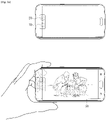
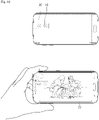
- the first and second camera modules 10, 20 may, for example, be arranged in a vertical direction on a rear surface of the photographing apparatus, as illustrated in FIG. 1A .
- the first and second camera modules 10, 20 may, for example, be arranged in a horizontal direction on a rear surface of the photographing apparatus, as illustrated in FIG. 1B .
- the first camera module 10 may include, for example, a wide-angle lens for a broad range of image photographing
- the second camera module 20 may include, for example, a telephoto lens for a long range of image photographing.
- the photographing apparatus may obtain images corresponding to a characteristic of the lens of each of the first and second camera modules 10, 20.
- the first camera module 10 may, for example, provide a wider image than the second camera module 10 which is focused at the same distance as the first camera module 10.
- the second camera module 20 may, for example, provide an image which is out of the range of the first camera module 10.
- a front surface of the photographing apparatus may include a display panel 30, and may be configured to determine an image generated by at least one of the first and second camera modules 10, 20 as a live image with respect to a subject to be photographed and display the determined image as the live image.
- the display panel 30 may display a live image with respect to the image generated by at least one of the first and second camera modules 10, 20 and receive a command with respect to the displayed live image.
- the photographing apparatus may photograph a still image or a moving image from the live image displayed in the display panel 30.
- the photographing apparatus may, for example, generate a composite image by composing the images generated by the first and second camera modules 10, 20 or generate a three-dimensional (3D) image.
- the photographing apparatus may determine the image generated by at least one of the first and second camera modules 10, 20 as a live image and display the image determined as the live image through the display panel 30.
- images may be generated through the first camera module 10 and the second camera module 20, and a live image with respect to the image generated by the first camera module 10 among the images generated by the first and second camera modules 10, 20 may be displayed through the display panel 30.
- a user's finger may come into contact with, for example, the second camera module 20 while the live image with respect to the image generated by the first camera module 10 is displayed.
- an image relevant to the user's finger may be inserted into a certain region of an image generated by the second camera module 20.
- the photographing apparatus determines that the an event (e.g., a finger being inserted into a region of an image) occurs by analyzing the image generated by the second camera module 20 and displays the image in which the event occurred in the display panel 30.
- the user may recognize that his/her finger came into contact with the second camera module 20 and move the finger to a region in which the first and second camera modules 10, 20 are not arranged.
- the photographing apparatus may analyze images generated by at least one of the first and second camera modules 10, 20, detect an image in which an event occurred, and display the detected image so that a user is able to recognize a current photographing state more intuitionally.
- FIG. 2 is a block diagram illustrating an example structure of an example photographing apparatus
- FIG. 3 is a more detailed block diagram illustrating an example structure of an example photographing apparatus.
- the photographing apparatus includes a photographing unit 110, a first buffer (e.g., including a memory) 120, a second buffer (e.g., including a memory) 130, a display 140, and a controller 150.
- the photographing apparatus may further include an image processor 160, a communicator (e.g., including communication circuitry) 170, an input unit (e.g., including input circuitry)180, and a storage 190, in addition to the components described above with reference to FIG. 2 .
- the photographing unit 110 for photographing an image may be applied to a photographing apparatus such as a Compact System Camera (CSC).
- the photographing unit 110 may include a plurality of camera modules 111, 113 (hereinafter referred to, for example, as 'first camera module' and 'second camera module').
- the first camera module 111 may include, for example, a wide-angle lens for a broad range of image photographing
- the second camera module 113 may include, for example, a telephoto lens for a long range of image photographing.
- the photographing unit 110 may obtain images corresponding to a characteristic of the lens of each of the first and second camera modules 111, 113.
- the photographing unit 110 may provide a wider image than the second camera module 113 which is focused at the same distance as the first camera module 111, through the first camera module 111.
- the photographing unit 110 may provide an image which is out of range of the first camera module 111, through the second camera module 113.
- the first and second camera modules 111, 113 receive external light admitted through the lens (the wide-angle lens and the telephoto lens) included in each camera module and convert the received external light into an electrical signal.
- the first and second camera modules 111, 113 may convert the external light formed on the imaging surface into an electrical signal using a photoelectric conversion device such as, for example, a Charge Coupled Device (CCD) or Complementary Metal Oxide Semiconductor (CMOS), or the like.
- a photoelectric conversion device such as, for example, a Charge Coupled Device (CCD) or Complementary Metal Oxide Semiconductor (CMOS), or the like.
- CCD Charge Coupled Device
- CMOS Complementary Metal Oxide Semiconductor
- a position of each lens included in the first and second camera modules 111, 113 may be changed based on a control command of the controller 150 thereby expanding or reducing a size of a subject to be photographed or performing autofocus for adjusting a focus with respect to a subject.
- the image processor 160 illustrated, for example, in FIG. 3 processes raw image data with respect to the electrical signal converted by the first and second camera modules 111, 113 of the photographing unit 110 to generate a live image with respect to the subject to be photographed.
- the above-described method for converting an external light into an electrical signal by using the photographing unit 110 and the image processor 160 and generating a live image from the converted electrical signal pertains to the common knowledge in the art in connection with a camera having an electric or optical viewfinder, and thus, the detailed description is omitted.
- the first buffer 120 temporarily stores a plurality of images generated by the first camera module 111 among the plurality of camera modules.
- the second buffer 130 temporarily stores a plurality of images generated by the second camera module 113 among the plurality of camera modules.
- the first and second buffers 120, 130 temporarily store the plurality of images generated by the first and second camera modules 111, 113 in connection with a subject to be photographed, before a command relevant to a photographing operation is received.
- it is desirable that the plurality images being temporarily stored in the first and second buffers 120, 130 are stored sequentially based on a generated order.
- the first and second buffers 120, 130 match and store at least one of the plurality of images being temporarily stored, image information on each image, and photographing information.
- the image information may include, for example, at least one of brightness information, histogram information, and pixel information of an image
- the photographing information may include at least one of lens position information for autofocus, phase difference information, and contrast level information of each camera module in connection with generating an image.
- the first and second buffers 120, 130 may, for example, match and store at least one of the plurality of images being temporarily stored, the image information of each image, and the photographing information.
- the display 140 displays the image generated by the first camera module 111 among the plurality of camera modules as a live image.
- the images generated by the first camera module 111 are displayed as a live view, but is not limited thereto.
- the image generated by the second camera module 113 among the plurality of camera modules may be also displayed as a live image.
- each of the image generated by the first and second camera modules 111, 113 may be displayed as a live image.
- the display 140 may display a photographed still image, a photographed moving image, and a command-related UI for controlling an operation of the photographing apparatus, on top of or overlapping a live image with respect to a subject to be photographed.
- the display 140 may, for example, be realized as a Liquid Crystal Display (LCD), Organic Light-Emitting Diode (OLED), Plasma Display Panel (PDP), etc. Further, the display 140 may, for example, be realized as a touch panel for receiving a touch command in connection with a displayed UI.
- the controller 150 is configured to analyze the images stored in the first buffer and second buffers 120, 130 using, for example, at least one of the image information of each image stored in the first and second buffers 120, 130 and the photographing information of the first and second camera modules 111, 113. In response to analyzing that an event occurs in at least one of the plurality of images stored in the second buffer 130, the controller 150 is configured to control the display 140 to provide a state notification service on the second camera module 113.
- An image in which an event occurred may, for example, be an image generated by the second camera module 113 while a part of or an entire part of the second camera module 113 is covered with a foreign substance, such as, for example, a user's finger, or, for example, an auto-focused image different from other images stored in the second buffer 130.
- a foreign substance such as, for example, a user's finger, or, for example, an auto-focused image different from other images stored in the second buffer 130.
- the controller 150 may be configured to control the display 140 to convert and display a live image with respect to the image generated by the first camera module 111 to the image in which the event occurred.
- the controller 150 may be configured to control the display 140 to display a live image with respect to the image generated by the first camera module 111 in a first region of the display 140 and display an event UI with respect to the image in which the event occurred in a second region on the display 140.
- the display 140 may include a main display 141 and a curved-surface auxiliary display 143 which is extended in a certain direction from the main display 141.
- the controller 150 may be configured to control the display 140 to display the live image with respect to the image generated by the first camera module 111 in the main display 141.
- the controller 150 may be configured to control the display 140 to display an event UI with respect to the image in which the event occurred, for example, the event UI with respect to the images generated by the second camera module 113, in the curved-surface auxiliary display 143.
- the display 140 may display the live image in the main display 141 and display the event UI with respect to the image in which the event occurred in the curved-surface auxiliary display 143.
- the controller 150 may be configured to control the communicator (e.g., including communication circuitry) 170 to transmit event occurrence-related information to an adjacent terminal apparatus (not shown).
- the communicator 170 may transmit the event occurrence-related information to the adjacent terminal apparatus (not shown), and the adjacent terminal apparatus (not shown) may provide a state notification service of the second camera module 113 based on the event occurrence-related information received from the photographing apparatus.
- the adjacent terminal apparatus may provide a notification that a photographing operation of the second camera module 113 may be performed abnormally through a notification service, such as, for example, a vibration feedback, a message alarm feedback, a beep sound feedback, a lamp alarm feedback, etc., based on the event occurrence-related information received from the photographing apparatus.
- a notification service such as, for example, a vibration feedback, a message alarm feedback, a beep sound feedback, a lamp alarm feedback, etc.
- the communicator 170 which transmits the event occurrence-related information to the adjacent terminal apparatus may include, for example, a local area communication module 171, a wireless communication module 173, such as, a wireless Local Area Network (LAN) module, and a connector 175 including at least one of wired communications modules such as a High Definition Multimedia Interface (HDMI), a Universal Serial Bus (USB), Institute of Electrical and Electronics Engineers (IEEE) 1394, etc.
- a local area communication module 171 such as, a wireless Local Area Network (LAN) module
- a connector 175 including at least one of wired communications modules such as a High Definition Multimedia Interface (HDMI), a Universal Serial Bus (USB), Institute of Electrical and Electronics Engineers (IEEE) 1394, etc.
- HDMI High Definition Multimedia Interface
- USB Universal Serial Bus
- IEEE 1394 Institute of Electrical and Electronics Engineers
- the local area communication module 171 may perform local area communication between the photographing apparatus and the adjacent terminal apparatus (not shown) in a wireless manner.
- the local area communication module 171 may include, for example, at least one of a Bluetooth module, an Infrared Data Association (IrDA) module, a Near Field Communication (NFC) module, a Wireless-Fidelity (Wi-Fi) module, and a Zigbee module, or the like.
- the wireless communication module 173 may be connected to an external network according to a wireless communication protocol, such as, for example, IEEE, to perform communication.
- the wireless communication module 173 may further include a mobile communication module which performs communication by accessing a mobile communication network according to diverse mobile communication standards such as 3rd Generation (3G), 3rd Generation Partnership Project (3GPP), Long Term Evolution (LTE), etc.
- 3G 3rd Generation
- 3GPP 3rd Generation Partnership Project
- LTE Long Term Evolution
- the communicator 170 may, for example, be realized by various local area communication methods, and other communication methods and/or communication circuitry which are not mentioned in the disclosure may be employed based on need.
- the connector 175 may provide an interface with respect to various source apparatuses, such as, USB 2.0, USB 3.0, HDMI, IEEE 1394, etc.
- the connector 175 may receive content data transmitted from an external server (not shown) or transmit pre-stored content data to an external recording medium through a wired cable connected to the connector 175, based on a control command of the controller 150.
- the connector 175 may be supplied with power through a wired cable which is physically connected to the connector 175.
- the input unit 180 may include, for example, input circuitry that serves as an input means for receiving various commands and transmitting the commands to the controller 150.
- the input unit 180 may include, for example, a manipulation unit (not shown) and a touch input unit (not shown) for receiving a user manipulation command and a second input unit (not shown) for receiving a control signal corresponding to a command from a remote control apparatus (not shown).
- the manipulation unit may, for example, be realized as a keypad having various function keys, number keys, special keys, letter keys, etc.
- the touch input unit may, for example, be realized as a touch pad forming a mutual layer structure with the display 140 in response to the display 140 being realized as a touch screen.
- the second input unit may, for example, receive a command, such as, a channel tuning command, a function setting command with respect to the photographing apparatus, etc., through a control command including an Infrared Rays (IR) signal, a Radio Frequency (RF) signal, and the like from the remote control apparatus (not shown) or a voice signal with respect to a user's uttered voice.
- a command such as, a channel tuning command, a function setting command with respect to the photographing apparatus, etc.
- a control command including an Infrared Rays (IR) signal, a Radio Frequency (RF) signal, and the like from the remote control apparatus (not shown) or a voice signal with respect to a user's uttered voice.
- IR Infrared Rays
- RF Radio Frequency
- the storage 190 may, for example, store diverse images and an Operating System (OS) for controlling the operations of the photographing apparatus.
- the OS may be a program which is read from the storage 190 and compiled to operate each component of a portable terminal apparatus 100 in response to the photographing apparatus being turned on.
- the storage 190 may, for example, be realized as at least one of Read-Only Memory (ROM), Random Access Memory (RAM), a memory card which is detachable or mountable with respect to a portable terminal apparatus 100 (for example, a Secure Digital (SD) card, a memory stick, etc.), a non-volatile memory, a volatile memory, a Hard Disk Drive (HDD), and a Solid State Disk (SDD), or the like.
- ROM Read-Only Memory
- RAM Random Access Memory
- SD Secure Digital
- HDD Hard Disk Drive
- SSD Solid State Disk
- the controller 150 In response to a composite photographing command being received through the input unit 180, the controller 150 is configured to generate a composite image from an image at a point of time when the composite photographing command is received among the images stored in the first and second buffers 120, 130 and to control the display 140 to display the generated composite image.
- the controller 150 is configured to generate depth information from a value of each pixel constituting the images stored in the first and second buffers 120, 130 and to compose each image based on the depth information.
- this method is only an example, and a composite image is generated from the images which are temporarily stored in the first and second buffers 120, 130 by various well-known composite algorithms.
- the display 140 displays the composite image obtained from the images stored in the first and second buffers 120, 130.
- the controller 150 is configured to generate a composite image from an image adjacent to the image in which the event occurred from among the images stored in the first buffer 120 and the images stored in the second buffer 130. For example, an image in which an event occurred at a point of time when the composite photographing command is received is detected. In this case, the controller 150 is configured to extract the image adjacent to the image in which the event occurred from the second buffer 130.
- the image adjacent to the image in which the event occurred is an image stored in the second buffer 130 immediately before the image in which the event occurred is temporarily stored in the second buffer 130.
- the controller 150 is configured to generate a composite image from the image stored at the point of time when the composite photographing command is received among the images stored in the first buffer 120 and the image extracted from the second buffer 130.
- the display 140 displays the composite image obtained from the images stored in the first and second buffers 120, 130.
- the controller 150 may be configured to determine whether it is possible to generate a composite image from the images stored in the first and second buffers 120, 130, according to the example discussed below.
- the controller 150 may be configured to determine whether to generate a composite image based on an occlusion region based on parallax of each image stored in the first and second buffers 120, 130 and a predetermined value (e.g., a predetermine critical value). For example, in response to a composite photographing command being received, the controller 150 may be configured to detect an occlusion region based on the parallax of each image stored in the first and second buffers 120, 130. The controller 150 may be configured to determine whether a detected amount of the detected occlusion region is greater than the predetermined value, for example, a predetermined critical value.
- a predetermined value e.g., a predetermine critical value
- the controller 150 may be configured to select one of the images stored in the first and second buffers 120, 130 and to control the display 140 to display the selected image.
- the display 140 may display the image selected from among the images stored in the first and second buffers 120, 130.
- the controller 150 may be configured to determine whether to generate a composite image based on focusing information of each of the first and second camera modules 111, 113 and close-up photographing information corresponding to a command.
- the first camera module 111 may include a wide-angle lens
- the second camera module 113 may include a telephoto lens.
- a photographable focusing distance may be applied differently to the first camera module 111 and the second camera module 113 based on the characteristic of the lens of each module.
- FIG. 4 is a demonstration diagram illustrating an example photographable focusing region of a plurality of camera modules of a photographing apparatus.
- the first camera module 111 having a wide-angle lens may focus on a subject, ranging from a first point (A) at a close distance to a third point (C) at a long distance.
- the second camera module 113 having a telephoto lens may focus on a subject, ranging from a second point (B) farther than the first point (A) at the close distance to the third point (C) at the long distance.
- the second camera module 113 having the telephoto lens may focus on a subject located at a relatively long distance as compared with the first camera module 111 having a wide-angle lens but is unable to focus on a subject located at a close distance.
- the controller 150 may be configured to determine that compositeness of the images generated by the second camera module 113 is unavailable based on the received close-up photographing information and the focusing information on the first and second camera modules 111, 113.
- the controller 150 may be configured to select an image stored in the first buffer 120 among the images stored in the first and second buffers 120, 130 and to control the display 140 to display the selected image.
- the display 140 may display the image selected from the images stored in the first buffer 120.
- FIG. 5A and 5B are demonstration diagrams illustrating an example of detecting an image in which an event occurred in a photographing apparatus.
- the controller 150 may be configured to analyze a plurality of images stored in the first and second buffers 120, 130 and to detect an image in which an event occurred. For example, as illustrated in FIG. 5A , the controller 150 may be configured to measure similarity in the images stored in the first buffer 120. In addition, as illustrated in FIG. 5B , the controller 150 may be configured to measure similarity in the images stored in the second buffer 130.
- the similarity in the images stored in the first and second buffers 120, 130 may be measured from at least one of brightness information, histogram information, and pixel information of an image.
- the controller 150 may be configured to determine that an event occurs in the image stored in the first buffer 120.
- the images stored in the first buffer 120 may be images generated by the first camera module 111.
- the controller may be configured to provide a state notification service on the first camera module 111 among the first and second camera modules 111, 113, according to the above-described various examples.
- a user is able to recognize that his/her finger covers the first camera module 111 intuitionally through the notification service and to move the finger covering the first camera module 111.
- the first and second camera modules 111, 113 may generate images with respect to a subject to be photographed normally.
- FIG. 6 is a diagram illustrating an example of generating a composite image in a photographing apparatus.
- FIG. 6 illustrates an example in which a plurality of images generated by the first camera module 111 are stored temporarily in the first buffer 120 based on a time sequence.
- the first and second camera modules 111, 113 generate images at the same timing, and the generated images are stored in the first and second buffers 120, 130 temporarily in a sequential order. For example, eight images are stored in the first and second buffers 120, 130, respectively, and a composite photographing command is input at a point of time when the eighth image is stored.
- the controller 150 is configured to compose eighth images 610-1, 610'-1 stored in the first and second buffers 120, 130 at the point of time the composite photographing command is input.
- the controller 150 is configured to determine whether an event has occurred based on at least one of the image information on the plurality of images respectively stored in the first and second buffers 120, 130 and the photographing information.
- the controller 150 may be configured to determine whether an event occurs using at least one of the brightness information, histogram information, and pixel information of the images stored in the first and second buffers 120, 130.
- the controller 150 may be configured to determine the similarity between two images based on the brightness information of the eighth images 610-1, 610'-1 respectively being stored in the first and second buffers 120, 130 at the point of time when the composite photographing command is received and the brightness information of preceding images (seventh images 610-2,610'-2). For example, the controller 150 may be configured to determine a difference value in brightness between two images based on the brightness information of the two images and to determine the similarity of the two images based on the determined difference value and a predetermined critical value. In response to determining that the determined difference value is greater than the predetermined critical value, the controller 150 may be configured to determine that the two images are similar to each other. In response to determining that the determined difference value is less than the predetermined critical value, the controller 150 may be configured to determine that the two images are different from each other.
- the controller 150 may be configured to detect the eighth image of a buffer of which two images are determined as being different, out of the first and second buffers 120, 130, as an image in which the event occurred.
- the controller 150 may be configured to determine whether an event occurs based on the photographing information including at least one of the lens position information for autofocus, phase difference information, and contrast level information on the first and second camera modules 111, 113.
- the controller 150 may be configured to compare the lens position information of the eighth images 610-1,610'-1 respectively being stored in the first and second buffers 120, 130 and the preceding images 610-2,610'-2 to determine a similarity between the two images. For example, the controller 150 may be configured to determine a distance difference between the lenses based on the lens position information on the two images. In response to the determined distance difference being less than a predetermined critical value, the controller 150 may be configured to determine that the two images are similar to each other. In response to the determined distance difference being greater than the predetermined critical value, the controller 150 may be configured to determine that the two images are different from each other.
- the controller 150 may be configured to detect the eighth image of a buffer of which two images are determined as being different, out of the first and second buffers 120, 130, as an image in which the event occurred.
- the controller 150 is configured to detect an image in which the event occurred.
- the eighth image 610'-1 of the second buffer 130 is detected as an image in which the event occurred.
- the controller 150 in response to the image in which the event occurred being detected, the controller 150 is configured to extract an image (the seventh image 610'-2) adjacent to the eighth image 610'-1 detected as the image in which the event occurred.
- the controller 150 is configured to generate a composite image by composing the eighth image 610-1 stored in the first buffer 120 and the seventh image 610'-2 stored in the second buffer 130.
- FIG. 7A and 7B are diagrams illustrating an example of providing a state notification service on a plurality of camera modules in a photographing apparatus.
- the photographing apparatus may determine and display an image 710 generated by the predetermined first camera module among the first and second camera modules 111, 113 as a live image.
- the photographing apparatus may temporarily store a plurality of images generated by the first camera module 111 in the first buffer 120 and temporarily store a plurality of images generated by the second camera module 113 in the second buffer 130.
- the photographing apparatus analyzes the plurality of images stored in the first and second buffers 120, 130 using, for example, at least one of the image information on each of the plurality of images stored in the first and second buffers 120, 130 and the photographing information.
- the photographing apparatus may determine and display the image in which the event occurred 720 as a live image. For example, the photographing apparatus may display a live image with respect to the image 720 including a foreign substance 721. Accordingly, a user is able to recognize that his/her finger covers a part of the lens of the second camera module 113 based on the displayed live image, move the finger to another place, and then perform a photographing operation.
- the photographing apparatus may photograph images or compose photographed images while no foreign substance exists on the first and second camera modules 111, 113.
- FIG. 8 is a diagram illustrating an example of providing a state notification service on a plurality of camera modules in a photographing.
- the photographing apparatus may display an image 710 generated by the predetermined first camera module 111 among the first and second camera modules 111, 113 as a live image.
- the photographing apparatus may temporarily store a plurality of images generated by the first camera module 111 in the first buffer 120 and temporarily store a plurality of images generated by the second camera module 113 in the second buffer 130.
- the photographing apparatus analyzes the plurality of images stored in the first and second buffers 120, 130 using, for example, at least one of the image information on each of the plurality of images stored in the first and second buffers 120, 130 and the photographing information.
- the photographing apparatus may display a live image 810 in the main display 141 and may display an event UI 820 with respect to the plurality of images stored in the second buffer 130, the plurality of images including the image in which the event occurred, in the curved-surface auxiliary display 143.
- the event UI displayed in the curved-surface auxiliary display 143 may be a thumbnail image corresponding to each of the plurality of images stored in the second buffer 130.
- the photographing image displays the live image 810 in the main display 141 and display thumbnail images corresponding to the plurality of images stored in the second buffer 130 including the image in which the event occurred in the curved-surface auxiliary display 143. Accordingly, a user is able to recognize that his/her finger covers a part of the lens of the second camera module 113 based on the thumbnail images displayed in the curved-surface auxiliary display 143, move the finger to another place, and then perform a photographing operation.
- the photographing apparatus may, for example, apply a highlight effect to a thumbnail image corresponding to an image in which the event occurred among the thumbnail images corresponding to the plurality of images displayed in the curved-surface auxiliary display 143, but is not limited thereto.
- the photographing apparatus may apply various event effects that a user is able to recognize to a thumbnail image corresponding to an image in which the event occurred among the thumbnail images corresponding to the plurality of images displayed in the curved-surface auxiliary display 143.
- the photographing apparatus may apply a highlight effect to the thumbnail image corresponding to the image in which the event occurred, the user is able to recognize that his/her finger covers a part of the lens of the second camera module 113 more intuitionally through the highlighted thumbnail image.
- FIG. 9A and FIG. 9 B are diagrams illustrating an example of providing a state notification service on a plurality of camera modules in a photographing.
- the photographing apparatus may determine an image 910 generated by the predetermined first camera module 111 among the first and second camera modules 111, 113 as a live image and display the image determined as the live image through the main display 141.
- the photographing apparatus may display an event UI 920 with respect to histogram information of an image generated by the second camera module 113 at a point of time when the image determined as the live image was generated through the curved-surface auxiliary display 143.
- the photographing apparatus may display the event UI 920 with respect to the histogram information in, for example, a strip form including a first color through the curved-surface auxiliary display 143.
- the photographing apparatus Before receiving a photographing command, the photographing apparatus may temporarily store a plurality of images generated by the first camera module 111 in the first buffer 120 and temporarily store a plurality of images generated by the second camera module 113 in the second buffer 130.
- the photographing apparatus analyzes the plurality of images stored in the first and second buffers 120, 130 using, for example, at least one of the image information on each of the plurality of images stored in the first and second buffers 120, 130 and the photographing information.
- the photographing apparatus may display an event UI 920' of which color has been changed to a second color different from the first color through the curved-surface auxiliary display 143.
- the photographing apparatus may provide the event UI 920' which displays an entire part of a display region of the curved-surface auxiliary display 143 in the second color different from the first color or provide the event UI 920' which displays a part of the display region of the curved-surface auxiliary display 143 in the second color.
- the photographing apparatus may determine a region in which the second color is displayed based on an order of storing the image in which the event occurred.
- the photographing apparatus may display a right region of the curved-surface auxiliary display 143 in the second color.
- a user is able to recognize, for example, that his/her finger covers a part of the lens of the second camera module 113 based on the color of an auxiliary region 20 displayed in the curved-surface auxiliary display 143, move the finger to another place, and then perform a photographing operation.
- the photographing apparatus may photograph images or compose photographed images while no foreign substance exists on the first and second camera modules 111, 113.
- FIG. 10 is a diagram illustrating an example of providing a state notification service on a plurality of camera modules in a photographing apparatus.
- the photographing apparatus may determine and display the image 710 generated by the predetermined first camera module 111 among the first and second camera modules 111, 113 as a live image.
- the photographing apparatus may temporarily store a plurality of images generated by the first camera module 111 in the first buffer 120 and temporarily store a plurality of images generated by the second camera module 113 in the second buffer 130.
- the photographing apparatus analyzes the plurality of images stored in the first and second buffers 120, 130 using, for example, at least one of the image information on each of the plurality of images stored in the first and second buffers 120, 130 and the photographing information.
- the photo graphing apparatus displays the live image in a first region 1010 of the main display 141 and display the image in which the event occurred in a second region 1020.
- the photographing apparatus may display an event UI 1030 including at least one of photographing information on the live image displayed in the first region 1010 and photographing information on the image in which the event occurred displayed in the second region 1020, through the curved-surface auxiliary display 143.
- the photographing apparatus may display a live image in one region of a screen and display the image in which the event occurred in other region of the screen.
- the photographing apparatus may display the photographing information on the image in which the event occurred in a certain part of a region where a live image is displayed.
- the photographing apparatus may display a live image in the main display 141 and may display a thumbnail image or histogram information on the image in which the event occurred in the curved-surface auxiliary display 143.
- the photographing apparatus may display at least one of the image information and the photographing information on the image in which the event occurred in a certain region of the main display 141 while displaying the thumbnail image or histogram information on the image in which the event occurred in the curved-surface auxiliary display 143.
- a user is able to perform the autofocus with respect to the second camera module 113 again based on the photographing information and then carry out a photographing operation.
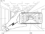
- FIG. 11 is a diagram illustrating an example of providing a state notification service on a plurality of camera modules in a photographing apparatus.
- the photographing apparatus may determine and display an image 1120 generated by the predetermined first camera module 111 among the first and second camera modules 111, 113 as a live image.
- the photographing apparatus may temporarily store a plurality of images generated by the first camera module 111 in the first buffer 120 and temporarily store a plurality of images generated by the second camera module 113 in the second buffer 130.
- the photographing apparatus analyzes the plurality of images stored in the first and second buffers 120, 130 using, for example, at least one of the image information on each of the plurality of images stored in the first and second buffers 120, 130 and the photographing information.
- the photographing apparatus may transmit event occurrence-related information to an adjacent terminal apparatus which is capable of performing data communication with the photographing apparatus.
- the adjacent terminal apparatus which is capable of performing data communication with the photographing apparatus may, for example, be a smart watch 1110 worn on a user's wrist.
- the photographing apparatus may transmit the event occurrence-related information to the smart watch 1110. Accordingly, the smart watch 1110 may provide a state notification service on the second camera module 113 based on the event occurrence-related information received from the photographing apparatus. According to an example, the smart watch 1110 may inform that a photographing operation of the second camera module 113 may be performed abnormally through a notification service such as a vibration feedback, a message alarm feedback, a beep sound feedback, a lamp alarm feedback, etc., based on the event occurrence-related information received from the photographing apparatus.
- a notification service such as a vibration feedback, a message alarm feedback, a beep sound feedback, a lamp alarm feedback, etc.
- a user is able to recognize that his/her finger covers a part of the lens of the second camera module 113 through the notification service provided through the smart watch 1110 being worn on his/her wrist, move the finger to another place, and then perform a photographing operation.
- the photographing apparatus may photograph images or compose photographed images while no foreign substance exists on the first and second camera modules 111, 113.
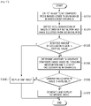
- FIG. 12 is a flowchart illustrating an example method for controlling a photographing apparatus.
- a photographing apparatus in response to an image being generated by at least one of a plurality of camera modules (e.g., a first camera module and a second camera module), a photographing apparatus displays the generated image in a screen in operation S1210. Before receiving a command relevant to a photographing operation, the photographing apparatus stores the image generated by at least one of the first camera module and the second camera module in a buffer in operation S1220.
- a plurality of camera modules e.g., a first camera module and a second camera module
- the photographing apparatus In response to images being generated by a plurality of camera modules, the photographing apparatus displays an image generated by the first camera module among the plurality of camera modules as a live image. In addition, before receiving a command relevant to a photographing operation, the photographing apparatus temporarily stores a plurality of images generated by the first camera module in a first buffer. In addition, before receiving a command relevant to a photographing operation, the photographing apparatus temporarily stores a plurality of images generated by the second camera module in a second buffer.
- the photographing apparatus temporarily stores the images generated by the first and second camera modules in the first and second buffers in a sequential order based on a time sequence.
- the photographing apparatus matches and stores at least one of image information on each image generated by the first and second camera modules and photographing information.
- the image information may include, for example, at least one of brightness information, histogram information, and pixel information of an image
- the photographing information may include at least one of lens position information for autofocus, phase difference information, and contrast level information in each camera module in connection with generating an image.
- the photographing apparatus analyzes the images stored in the first and second buffers by using at least one of the image information on each image stored in the first and second buffers and the photographing information of the first and second camera modules and determines whether there is an image in which an event occurred in operation S1230.
- the photographing apparatus provides a state notification service on a camera module relevant to the image in which the event occurred in operations S1240 and S1250.
- the photographing apparatus In response to an event occurring in an image stored in the second buffer based on at least one of the image information of each image stored in the first and second buffers and the photographing information, the photographing apparatus provides a state notification service on the second camera module relevant to the image in which the event occurred.
- the image in which the event occurred is an image generated by the second camera module while a part of or an entire part of the second camera module is covered with a foreign substance, such as, a finger, or an auto-focused image different from other images stored in the second buffer.
- the photographing apparatus in response to the image in which the event occurred being detected, converts and display a live image with respect to the image generated by the first camera module to the image in which the event occurred.
- the photographing apparatus may display a live image with respect to the image generated by the first camera module in a first region of a screen and display an event UI with respect to the image in which the event occurred in a second region of the screen.
- the first region may be a region displayed through a main display
- the second region may be a region displayed through a curved-surface auxiliary display extended in a certain direction from the main display.
- the photographing apparatus may display the live image with respect to the image generated by the first camera module in the first region displayed through the main display and display the image in which the event occurred, that is, the event UI with respect to the image generated by the second camera module, in the second region displayed through, for example, the curved-surface auxiliary display.
- the event UI may, for example, be a UI for providing a thumbnail image with respect to the image in the second buffer including the image in which the event occurred or a UI for providing histogram information on the image in the second buffer.
- the photographing apparatus may transmit event occurrence-related information to an adjacent terminal apparatus (not shown) which is capable of performing communication with the photographing apparatus. Accordingly, the adjacent terminal apparatus (not shown) may provide a state notification service on the second camera module based on the event occurrence-related information received from the photographing apparatus. According to an example, the adjacent terminal apparatus (not shown) may inform that a photographing operation of the second camera module may be performed abnormally through a notification service such as a vibration feedback, a message alarm feedback, a beep sound feedback, a lamp alarm feedback, etc., based on the event occurrence-related information received from the photographing apparatus.
- a notification service such as a vibration feedback, a message alarm feedback, a beep sound feedback, a lamp alarm feedback, etc.
- a user is able to recognize that his/her finger covers a part of or an entire part of the lens of the second camera module, move the finger to another place, and then perform a photographing operation.
- the photographing apparatus photographs images or composes photographed images while no foreign substance exists on the first and second camera modules, in operation S1260.
- FIG. 13 is a flowchart illustrating an example method for generating a composite image from images generated in a plurality of camera modules in a photographing apparatus.
- the photographing apparatus may receive a compositeness-related photographing command while at least one of the images stored in the first and second buffers has been detected as an image in which an event occurred.
- the photographing apparatus selects an image to be composed from among the images stored in the first and second buffers, excluding the image in which the event occurred, in operation S1310.
- the photographing apparatus selects an image adjacent to the image being detected as the image in which the event occurred as an image to be composed.
- the photographing apparatus may detect an occlusion region based on parallax between the image stored in the first buffer at a point of time when the composite command was received and the image selected from the second buffer, in operation S1320.
- the photographing apparatus determines whether an amount of the detected occlusion region is greater than a predetermined critical value, in operation S1330.
- the photographing apparatus selects one image from among the images stored in the first buffer at the point of time when the composite command was received and the image selected from the second buffer and displays the selected image, in operation S1340.
- the photographing apparatus determines whether it is possible to generate a composite image based on focusing information on each of the image stored in the first buffer at the point of time when the compositeness-related user command was received and the image selected from the second buffer and close-up photographing information corresponding to a user command, in operation S1350.
- the first camera module may include a wide-angle lens
- the second camera module may include a telephoto lens. Accordingly, a photographable focusing distance may be applied differently to the first camera module and the second camera module according the characteristic of the lens of each module.
- the photographing apparatus may determine whether to generate a composite image based on the focusing information on each of the image stored in the first buffer at the point of time when the composite command was received and the image selected from the second buffer and the close-up photographing information corresponding to the command.
- the photographing apparatus In response to determining that a composing operation with respect to the image stored in the first buffer at the point of time when the compositeness-related user command was received and the image selected from the second buffer is available, the photographing apparatus generates a composite image from the two images and displays the composite image, in operations S1360 and S1370.
- the photographing apparatus selects one of the images stored in the first buffer at the point of time when the composite command was received and the image selected from the second buffer based on the above-described operation S1340 and displays the selected image.
- the photographing apparatus and method for controlling the same may be implemented in a program provided to the display apparatus.
- the program including the portable terminal apparatus and control method may be stored and provided in a non-transitory computer readable medium.
- the non-transitory computer readable medium may include a machine-readable medium semi-permanently storing the data.
- various applications or programs described above may be stored and provided in the non-transitory computer readable medium such as a compact disc (CD), a digital versatile disk (DVD), a hard disk, a Blu-ray disk, a universal serial bus (USB), a memory card, a read-only memory (ROM), or the like.
Landscapes
- Engineering & Computer Science (AREA)
- Multimedia (AREA)
- Signal Processing (AREA)
- Human Computer Interaction (AREA)
- Studio Devices (AREA)
Claims (10)
- Fotografiervorrichtung, die Folgendes umfasst:eine Vielzahl von Kameramodulen (10, 20, 111, 113), die sich auf der selben Seite der Fotografiervorrichtung befinden und so konfiguriert sind, dass sie zur gleichen Zeit Bilder erzeugen;einen ersten Puffer (120), der so konfiguriert ist, dass er eine Vielzahl von Bildern, die von einem ersten Kameramodul (111) aus der Vielzahl von Kameramodulen erzeugt werden, in einer sequentiellen Reihenfolge vorübergehend speichert, bevor ein Fotografierbefehl empfangen wird;einen zweiten Puffer (130), der so konfiguriert ist, dass er eine Vielzahl von Bildern, die von einem zweiten Kameramodul (113) aus der Vielzahl von Kameramodulen erzeugt werden, in einer sequentiellen Reihenfolge vorübergehend speichert, bevor ein Fotografierbefehl empfangen wird;eine Anzeige (140), die so konfiguriert ist, dass sie ein von dem ersten Kameramodul erzeugtes Bild als ein Live-Bild anzeigt; undeine Steuerung (150), die konfiguriert ist, um die in dem ersten Puffer und dem zweiten Puffer gespeicherten Bilder unter Verwendung von Bildinformationen jedes in dem ersten Puffer und dem zweiten Puffer gespeicherten Bildes und/oder von Fotografierinformationen der Vielzahl von Kameramodulen zu analysieren, um das Auftreten eines Ereignisses zu erfassen, das eine Behinderung des zweiten Kameramoduls durch ein Fremdobjekt umfasst, und um als Reaktion auf die Erfassung eines Ereignisses, das in mindestens einem aus der Vielzahl von Bildern auftritt, die in dem zweiten Puffer gespeichert sind, um die Anzeige so zu steuern, dass sie einen Statusbenachrichtigungsdienst in Bezug auf das zweite Kameramodul bereitstellt;wobei als Reaktion auf einen von einem Benutzer empfangenen Fotografierbefehl die Steuerung (150) konfiguriert ist, um ein zusammengesetztes Bild aus den in dem ersten Puffer und dem zweiten Puffer gespeicherten Bildern zu erzeugen und die Anzeige (140) so zu steuern, dass sie das erzeugte zusammengesetzte Bild anzeigt;wobei, wenn der Fotografierbefehl empfangen wird, während mindestens eines der in dem zweiten Puffer gespeicherten Bilder als ein Bild erkannt wurde, in dem ein Ereignis aufgetreten ist, die Steuerung (150) konfiguriert ist, um das Bild zu extrahieren, das in dem zweiten Puffer unmittelbar vor dem Bild gespeichert wurde, in dem das Ereignis aufgetreten ist, und um das zusammengesetzte Bild aus dem Bild unter den in dem ersten Puffer gespeicherten Bildern, das zu dem Zeitpunkt, zu dem der Fotografierbefehl empfangen wurde, gespeichert wurde, und dem aus dem zweiten Puffer extrahierten Bild zu erzeugen, und wobei die Steuerung andernfalls konfiguriert ist, um das zusammengesetzte Bild aus den Bildern zu erzeugen, die zu dem Zeitpunkt, zu dem der Fotografierbefehl empfangen wurde, in dem ersten Puffer und dem zweiten Puffer gespeichert wurden.
- Vorrichtung nach Anspruch 1, wobei die Steuerung (150) dazu konfiguriert ist, die Anzeige so zu steuern, dass sie das Bild, in dem das Ereignis aufgetreten ist, als das Live-Bild umwandelt und anzeigt, um den Statusbenachrichtigungsdienst in Bezug auf das zweite Kameramodul durch die Anzeige bereitzustellen.
- Vorrichtung nach Anspruch 1, wobei die Anzeige (140) Folgendes umfasst:eine Hauptanzeige (141); undeine Hilfsanzeige (143) mit gekrümmter Oberfläche, die so konfiguriert ist, dass sie sich von der Hauptanzeige in eine gewisse Richtung erstreckt,wobei die Steuerung dazu konfiguriert ist, die Anzeige so zu steuern, dass sie das Live-Bild in der Hauptanzeige anzeigt, und dazu, eine Ereignis-Benutzerschnittstelle (UI) in Bezug auf das Bild, in dem das Ereignis aufgetreten ist, in der Hilfsanzeige mit gekrümmter Oberfläche anzuzeigen, um den Statusbenachrichtigungsdienst in Bezug auf das zweite Kameramodul durch die Anzeige bereitzustellen.
- Vorrichtung nach Anspruch 1, wobei die Bildinformationen mindestens eine der Folgenden umfassen: Helligkeitsinformationen, Histogramminformationen und Pixelinformationen eines Bildes,
wobei die Fotografierinformationen mindestens eine der Folgenden umfassen: Objektivpositionsinformationen für Autofokus, Phasendifferenzinformationen und Kontrastpegelinformationen von mindestens einem aus der Vielzahl von Kameramodulen, und wobei der erste Puffer (120) und der zweite Puffer (130) die Bildinformationen jedes Bildes und die Fotografierinformationen abgleichen und speichern. - Vorrichtung nach Anspruch 1, wobei die Steuerung (150) so konfiguriert ist, dass sie einen Okklusionsbereich basierend auf einer Parallaxe jedes der in dem ersten Puffer (120) und dem zweiten Puffer (130) gespeicherten Bilder erfasst, und dass sie bestimmt, ob das zusammengesetzte Bild basierend darauf erzeugt werden soll, ob eine erfasste Menge des Okklusionsbereichs größer als ein vorbestimmter kritischer Wert ist.
- Vorrichtung nach Anspruch 1, wobei das erste Kameramodul (111) ein Weitwinkelobjektiv umfasst und das zweite Kameramodul (113) ein Teleobjektiv umfasst, und
wobei die Steuerung konfiguriert ist, um zu bestimmen, ob das zusammengesetzte Bild basierend auf Fokussierungsinformationen sowohl des ersten Kameramoduls (111) als auch des zweiten Kameramoduls (113) sowie auf Nahaufnahmenfotografierinformationen entsprechend einem Befehl erzeugt werden soll. - Verfahren zum Steuern einer Fotografiervorrichtung mit einer Vielzahl von Kameramodulen, die sich auf der selben Seite der Fotografiervorrichtung befinden und so konfiguriert sind, dass sie zur gleichen Zeit Bilder erzeugen, umfassend:Anzeigen (S1210) eines Bildes, das von einem ersten Kameramodul aus der Vielzahl von Kameramodulen erzeugt wird, als ein Live-Bild;vorübergehendes Speichern (S 1220) von durch das erste Kameramodul erzeugten Bildern in einer sequentiellen Reihenfolge in einem ersten Puffer und Speichern von durch ein zweites Kameramodul aus der Vielzahl von Kameramodulen erzeugten Bildern in einem zweiten Puffer, bevor ein Fotografierbefehl empfangen wird;Analysieren (S 1230) der in dem ersten Puffer und dem zweiten Puffer gespeicherten Bilder unter Verwendung von Bildinformationen jedes in dem ersten Puffer und dem zweiten Puffer gespeicherten Bildes und/oder von Fotografierinformationen der Vielzahl von Kameramodulen, um das Eintreten eines Ereignisses zu erfassen, das eine Behinderung des zweiten Kameramoduls durch ein Fremdobjekt umfasst;Bereitstellen (S1250) eines Statusbenachrichtigungsdienstes in Bezug auf das zweite Kameramodul als Reaktion auf die Erfassung eines Ereignisses, das in mindestens einem aus der Vielzahl von Bildern auftritt (S1240), die in dem zweiten Puffer gespeichert sind;Erzeugen (S 1260) eines zusammengesetzten Bildes aus den Bildern, die in den ersten und zweiten Puffern gespeichert sind, als Reaktion auf einen von einem Benutzer empfangenen Fotografierbefehl; undAnzeigen (S1370) des erzeugten zusammengesetzten Bildes,wobeiExtrahieren des Bildes, das in dem zweiten Puffer unmittelbar vor dem Bild gespeichert wurde, in dem das Ereignis aufgetreten ist, wenn der Fotografierbefehl empfangen wird, während mindestens eines der in dem zweiten Puffer gespeicherten Bilder als ein Bild erkannt wurde, in dem ein Ereignis aufgetreten ist, undErzeugen des zusammengesetzten Bildes aus dem Bild unter den in dem ersten Puffer gespeicherten Bildern, das zu dem Zeitpunkt, zu dem der Fotografierbefehl empfangen wurde, gespeichert wurde, und dem aus dem zweiten Puffer extrahierten Bild, und andernfallsErzeugen des zusammengesetzten Bildes aus den Bildern, die zu dem Zeitpunkt, zu dem der Fotografierbefehl empfangen wurde, in dem ersten Puffer und dem zweiten Puffer gespeichert wurden.
- Verfahren nach Anspruch 7, wobei als Reaktion auf die Erfassung eines Bildes, in dem das Ereignis aufgetreten ist, das Bereitstellen Folgendes umfasst: Umwandeln und Anzeigen des Bildes, in dem das Ereignis aufgetreten ist, als das Live-Bild, um den Statusbenachrichtigungsdienst in Bezug auf das zweite Kameramodul durch die Anzeige bereitzustellen.
- Verfahren nach Anspruch 7, wobei als Reaktion auf die Erfassung eines Bildes, in dem das Ereignis aufgetreten ist, das Bereitstellen Folgendes umfasst: Anzeigen des Live-Bildes in einer Hauptanzeige und Anzeigen einer Ereignis-Benutzerschnittstelle (UI) in Bezug auf das Bild, in dem das Ereignis aufgetreten ist, in einer Hilfsanzeige mit gekrümmter Oberfläche, die sich von der Hauptanzeige erstreckt, um den Statusbenachrichtigungsdienst in Bezug auf das zweite Kameramodul durch die Anzeige bereitzustellen.
- Verfahren nach Anspruch 7, wobei die Bildinformationen mindestens eine der Folgenden umfassen: Helligkeitsinformationen, Histogramminformationen und Pixelinformationen eines Bildes,
wobei die Fotografierinformationen mindestens eine der Folgenden umfassen: Objektivpositionsinformationen für Autofokus, Phasendifferenzinformationen und Kontrastpegelinformationen von mindestens einem aus der Vielzahl von Kameramodulen, und wobei der erste Puffer und der zweite Puffer die Bildinformationen jedes Bildes und die Fotografierinformationen abgleichen und speichern.
Applications Claiming Priority (2)
| Application Number | Priority Date | Filing Date | Title |
|---|---|---|---|
| KR1020150115540A KR102327842B1 (ko) | 2015-08-17 | 2015-08-17 | 촬영 장치 및 그 제어 방법 |
| PCT/KR2016/002703 WO2017030262A1 (en) | 2015-08-17 | 2016-03-17 | Photographing apparatus and method for controlling the same |
Publications (3)
| Publication Number | Publication Date |
|---|---|
| EP3338445A1 EP3338445A1 (de) | 2018-06-27 |
| EP3338445A4 EP3338445A4 (de) | 2018-08-29 |
| EP3338445B1 true EP3338445B1 (de) | 2022-11-23 |
Family
ID=58052233
Family Applications (1)
| Application Number | Title | Priority Date | Filing Date |
|---|---|---|---|
| EP16837204.3A Active EP3338445B1 (de) | 2015-08-17 | 2016-03-17 | Fotografievorrichtung und verfahren zur steuerung davon |
Country Status (5)
| Country | Link |
|---|---|
| US (1) | US9848128B2 (de) |
| EP (1) | EP3338445B1 (de) |
| KR (1) | KR102327842B1 (de) |
| CN (1) | CN107925729B (de) |
| WO (1) | WO2017030262A1 (de) |
Families Citing this family (11)
| Publication number | Priority date | Publication date | Assignee | Title |
|---|---|---|---|---|
| WO2014199338A2 (en) * | 2013-06-13 | 2014-12-18 | Corephotonics Ltd. | Dual aperture zoom digital camera |
| KR102401659B1 (ko) * | 2017-03-23 | 2022-05-25 | 삼성전자 주식회사 | 전자 장치 및 이를 이용한 카메라 촬영 환경 및 장면에 따른 영상 처리 방법 |
| KR102569375B1 (ko) | 2018-10-24 | 2023-08-22 | 삼성전자주식회사 | 전자 장치 및 전자 장치의 제어 방법 |
| KR102788816B1 (ko) | 2018-11-08 | 2025-03-31 | 삼성전자주식회사 | 전자 장치 및 그 제어 방법 |
| CN110248101B (zh) * | 2019-07-19 | 2021-07-09 | Oppo广东移动通信有限公司 | 对焦方法和装置、电子设备、计算机可读存储介质 |
| US11350018B2 (en) * | 2019-08-06 | 2022-05-31 | Apple Inc. | Camera with bumper for cushioning lateral movement |
| KR102679543B1 (ko) | 2019-12-09 | 2024-07-01 | 삼성전자 주식회사 | 디스플레이의 지정된 영역에 표시를 변경하는 전자 장치 및 이의 동작 방법 |
| US11451694B1 (en) * | 2021-03-16 | 2022-09-20 | International Business Machines Corporation | Mitigation of obstacles while capturing media content |
| CN113315940A (zh) * | 2021-03-23 | 2021-08-27 | 海南视联通信技术有限公司 | 一种视频通话方法、装置及计算机可读存储介质 |
| JP7793301B2 (ja) * | 2021-06-10 | 2026-01-05 | キヤノン株式会社 | 情報処理装置、情報処理方法およびプログラム |
| JP7692756B2 (ja) * | 2021-07-30 | 2025-06-16 | 株式会社キーエンス | 分析装置、分析方法、分析プログラム及び分析プログラムを記憶したコンピュータ読取可能な記憶媒体 |
Family Cites Families (21)
| Publication number | Priority date | Publication date | Assignee | Title |
|---|---|---|---|---|
| US20060187322A1 (en) * | 2005-02-18 | 2006-08-24 | Janson Wilbert F Jr | Digital camera using multiple fixed focal length lenses and multiple image sensors to provide an extended zoom range |
| US7551754B2 (en) * | 2006-02-24 | 2009-06-23 | Fotonation Vision Limited | Method and apparatus for selective rejection of digital images |
| US20090262125A1 (en) * | 2008-04-18 | 2009-10-22 | Vasanth Swaminathan | Rendering A Multiple Viewpoint Image Into A Single Frame Buffer Using Off-Screen Rendering Surfaces |
| JP2009272840A (ja) * | 2008-05-03 | 2009-11-19 | Olympus Imaging Corp | 画像記録再生装置、画像記録再生方法、画像処理装置、および画像処理方法 |
| US8355042B2 (en) * | 2008-10-16 | 2013-01-15 | Spatial Cam Llc | Controller in a camera for creating a panoramic image |
| US8416282B2 (en) * | 2008-10-16 | 2013-04-09 | Spatial Cam Llc | Camera for creating a panoramic image |
| JP2011078047A (ja) * | 2009-10-02 | 2011-04-14 | Sanyo Electric Co Ltd | 撮像装置 |
| JP4957850B2 (ja) * | 2010-02-04 | 2012-06-20 | カシオ計算機株式会社 | 撮像装置、警告方法、および、プログラム |
| JP2012023546A (ja) * | 2010-07-14 | 2012-02-02 | Jvc Kenwood Corp | 制御装置、立体映像撮像装置、および制御方法 |
| US20130128072A1 (en) * | 2010-09-08 | 2013-05-23 | Nec Corporation | Photographing device and photographing method |
| US9204026B2 (en) * | 2010-11-01 | 2015-12-01 | Lg Electronics Inc. | Mobile terminal and method of controlling an image photographing therein |
| US8451344B1 (en) * | 2011-03-24 | 2013-05-28 | Amazon Technologies, Inc. | Electronic devices with side viewing capability |
| JP2013162348A (ja) | 2012-02-06 | 2013-08-19 | Nikon Corp | 撮像装置 |
| KR20140060760A (ko) | 2012-11-12 | 2014-05-21 | 엘지전자 주식회사 | 어레이 카메라, 휴대 단말기 및 그 동작 방법 |
| KR101954192B1 (ko) | 2012-11-15 | 2019-03-05 | 엘지전자 주식회사 | 어레이 카메라, 휴대 단말기 및 그 동작 방법 |
| US9247223B2 (en) * | 2013-01-25 | 2016-01-26 | Blackberry Limited | Reduce operating environment effect using multiple cameras |
| KR102070776B1 (ko) * | 2013-03-21 | 2020-01-29 | 엘지전자 주식회사 | 디스플레이 장치 및 그 제어 방법 |
| DE102013103971A1 (de) | 2013-04-19 | 2014-11-06 | Sensovation Ag | Verfahren zum Erzeugen eines aus mehreren Teilbildern zusammengesetzten Gesamtbilds eines Objekts |
| KR102031142B1 (ko) * | 2013-07-12 | 2019-10-11 | 삼성전자주식회사 | 영상 디스플레이를 제어하는 전자 장치 및 방법 |
| KR20150093013A (ko) * | 2014-02-06 | 2015-08-17 | 삼성전자주식회사 | 사용자 단말 장치, 디스플레이 장치 및 그 제어 방법 |
| CN104618627B (zh) * | 2014-12-31 | 2018-06-08 | 小米科技有限责任公司 | 视频处理方法和装置 |
-
2015
- 2015-08-17 KR KR1020150115540A patent/KR102327842B1/ko active Active
-
2016
- 2016-03-08 US US15/063,751 patent/US9848128B2/en active Active
- 2016-03-17 EP EP16837204.3A patent/EP3338445B1/de active Active
- 2016-03-17 CN CN201680047437.8A patent/CN107925729B/zh active Active
- 2016-03-17 WO PCT/KR2016/002703 patent/WO2017030262A1/en not_active Ceased
Also Published As
| Publication number | Publication date |
|---|---|
| KR102327842B1 (ko) | 2021-11-18 |
| EP3338445A4 (de) | 2018-08-29 |
| CN107925729A (zh) | 2018-04-17 |
| WO2017030262A1 (en) | 2017-02-23 |
| KR20170021125A (ko) | 2017-02-27 |
| CN107925729B (zh) | 2021-01-05 |
| US20170054911A1 (en) | 2017-02-23 |
| US9848128B2 (en) | 2017-12-19 |
| EP3338445A1 (de) | 2018-06-27 |
Similar Documents
| Publication | Publication Date | Title |
|---|---|---|
| EP3338445B1 (de) | Fotografievorrichtung und verfahren zur steuerung davon | |
| EP3172894B1 (de) | Vorrichtung und verfahren zum fotografieren von bildern | |
| EP3335416B1 (de) | Digitalfotografievorrichtung und zugehöriges betriebsverfahren | |
| EP2587407B1 (de) | Visuelles Erkennungssystem und Verfahren | |
| CN101388965B (zh) | 数据处理装置和数据处理方法 | |
| JP6679577B2 (ja) | 3dパノラマイメージ生成のための映像生成装置及び方法 | |
| US20150172531A1 (en) | Image capturing apparatus, communication apparatus, and control method therefor | |
| KR20150061277A (ko) | 영상 촬영 장치 및 이의 영상 촬영 방법 | |
| US8576320B2 (en) | Digital photographing apparatus and method of controlling the same | |
| US9207768B2 (en) | Method and apparatus for controlling mobile terminal using user interaction | |
| TW201902204A (zh) | 通過按需感測器啟動來實現一多感測器攝像頭設備中的功率降低 | |
| KR102173109B1 (ko) | 디지털 영상 처리 방법, 상기 방법을 기록한 컴퓨터 판독 가능 저장매체 및 디지털 영상 처리 장치 | |
| CN103973965A (zh) | 图像拍摄设备、图像拍摄方法以及图像拍摄程序 | |
| JP6387700B2 (ja) | 情報処理装置、情報処理システム、情報処理装置の制御方法およびプログラム | |
| US11165970B2 (en) | Image processing apparatus, imaging apparatus, image processing method, and non-transitory computer readable medium | |
| CN114342350B (zh) | 成像控制装置、成像控制方法、程序以及成像设备 | |
| US7936988B2 (en) | Imaging apparatus and control method therefor | |
| US9661237B2 (en) | Image capturing apparatus, control method thereof, and storage medium | |
| EP4312433A1 (de) | Anzeigesteuerungsvorrichtung, anzeigesteuerungsverfahren, programm und speichermedium | |
| KR101812585B1 (ko) | Ui 제공 방법 및 이를 적용한 영상 촬영 장치 | |
| EP4216539A2 (de) | Bildverarbeitungsvorrichtung, bildverarbeitungsverfahren und programm | |
| US10411761B2 (en) | Communication apparatus capable of communicating with external apparatus, control method, and recording medium | |
| US9407821B2 (en) | Electronic apparatus and method of controlling the same | |
| JP2023063765A (ja) | 画像処理装置、画像処理方法、画像処理システム、およびプログラム | |
| KR20150143138A (ko) | 이미지 촬영 장치, 이미지 촬영 방법, 및 비 일시적 기록 매체 |
Legal Events
| Date | Code | Title | Description |
|---|---|---|---|
| STAA | Information on the status of an ep patent application or granted ep patent |
Free format text: STATUS: THE INTERNATIONAL PUBLICATION HAS BEEN MADE |
|
| PUAI | Public reference made under article 153(3) epc to a published international application that has entered the european phase |
Free format text: ORIGINAL CODE: 0009012 |
|
| STAA | Information on the status of an ep patent application or granted ep patent |
Free format text: STATUS: REQUEST FOR EXAMINATION WAS MADE |
|
| 17P | Request for examination filed |
Effective date: 20180116 |
|
| AK | Designated contracting states |
Kind code of ref document: A1 Designated state(s): AL AT BE BG CH CY CZ DE DK EE ES FI FR GB GR HR HU IE IS IT LI LT LU LV MC MK MT NL NO PL PT RO RS SE SI SK SM TR |
|
| AX | Request for extension of the european patent |
Extension state: BA ME |
|
| A4 | Supplementary search report drawn up and despatched |
Effective date: 20180726 |
|
| RIC1 | Information provided on ipc code assigned before grant |
Ipc: H04N 5/232 20060101ALI20180720BHEP Ipc: H04N 5/265 20060101AFI20180720BHEP Ipc: H04N 5/262 20060101ALI20180720BHEP Ipc: H04N 5/225 20060101ALI20180720BHEP |
|
| DAV | Request for validation of the european patent (deleted) | ||
| DAX | Request for extension of the european patent (deleted) | ||
| STAA | Information on the status of an ep patent application or granted ep patent |
Free format text: STATUS: EXAMINATION IS IN PROGRESS |
|
| 17Q | First examination report despatched |
Effective date: 20190426 |
|
| REG | Reference to a national code |
Ref country code: DE Ref legal event code: R079 Ref document number: 602016076519 Country of ref document: DE Free format text: PREVIOUS MAIN CLASS: H04N0005265000 Ipc: H04N0005225000 |
|
| GRAP | Despatch of communication of intention to grant a patent |
Free format text: ORIGINAL CODE: EPIDOSNIGR1 |
|
| STAA | Information on the status of an ep patent application or granted ep patent |
Free format text: STATUS: GRANT OF PATENT IS INTENDED |
|
| RIC1 | Information provided on ipc code assigned before grant |
Ipc: H04N 5/232 20060101ALI20220701BHEP Ipc: H04N 5/225 20060101AFI20220701BHEP |
|
| INTG | Intention to grant announced |
Effective date: 20220725 |
|
| RIN1 | Information on inventor provided before grant (corrected) |
Inventor name: LEE, TAE-HEE Inventor name: KIM, JAE-GON Inventor name: HAN, HEE-CHUL Inventor name: KANG, KWON-JEONG Inventor name: MOON, KYOUNG-HWAN |
|
| GRAS | Grant fee paid |
Free format text: ORIGINAL CODE: EPIDOSNIGR3 |
|
| GRAA | (expected) grant |
Free format text: ORIGINAL CODE: 0009210 |
|
| STAA | Information on the status of an ep patent application or granted ep patent |
Free format text: STATUS: THE PATENT HAS BEEN GRANTED |
|
| AK | Designated contracting states |
Kind code of ref document: B1 Designated state(s): AL AT BE BG CH CY CZ DE DK EE ES FI FR GB GR HR HU IE IS IT LI LT LU LV MC MK MT NL NO PL PT RO RS SE SI SK SM TR |
|
| REG | Reference to a national code |
Ref country code: GB Ref legal event code: FG4D |
|
| REG | Reference to a national code |
Ref country code: DE Ref legal event code: R079 Ref document number: 602016076519 Country of ref document: DE Free format text: PREVIOUS MAIN CLASS: H04N0005225000 Ipc: H04N0023000000 |
|
| REG | Reference to a national code |
Ref country code: CH Ref legal event code: EP |
|
| REG | Reference to a national code |
Ref country code: AT Ref legal event code: REF Ref document number: 1533869 Country of ref document: AT Kind code of ref document: T Effective date: 20221215 Ref country code: DE Ref legal event code: R096 Ref document number: 602016076519 Country of ref document: DE |
|
| REG | Reference to a national code |
Ref country code: IE Ref legal event code: FG4D |
|
| REG | Reference to a national code |
Ref country code: LT Ref legal event code: MG9D |
|
| REG | Reference to a national code |
Ref country code: NL Ref legal event code: MP Effective date: 20221123 |
|
| REG | Reference to a national code |
Ref country code: AT Ref legal event code: MK05 Ref document number: 1533869 Country of ref document: AT Kind code of ref document: T Effective date: 20221123 |
|
| PG25 | Lapsed in a contracting state [announced via postgrant information from national office to epo] |
Ref country code: SE Free format text: LAPSE BECAUSE OF FAILURE TO SUBMIT A TRANSLATION OF THE DESCRIPTION OR TO PAY THE FEE WITHIN THE PRESCRIBED TIME-LIMIT Effective date: 20221123 Ref country code: PT Free format text: LAPSE BECAUSE OF FAILURE TO SUBMIT A TRANSLATION OF THE DESCRIPTION OR TO PAY THE FEE WITHIN THE PRESCRIBED TIME-LIMIT Effective date: 20230323 Ref country code: NO Free format text: LAPSE BECAUSE OF FAILURE TO SUBMIT A TRANSLATION OF THE DESCRIPTION OR TO PAY THE FEE WITHIN THE PRESCRIBED TIME-LIMIT Effective date: 20230223 Ref country code: LT Free format text: LAPSE BECAUSE OF FAILURE TO SUBMIT A TRANSLATION OF THE DESCRIPTION OR TO PAY THE FEE WITHIN THE PRESCRIBED TIME-LIMIT Effective date: 20221123 Ref country code: FI Free format text: LAPSE BECAUSE OF FAILURE TO SUBMIT A TRANSLATION OF THE DESCRIPTION OR TO PAY THE FEE WITHIN THE PRESCRIBED TIME-LIMIT Effective date: 20221123 Ref country code: ES Free format text: LAPSE BECAUSE OF FAILURE TO SUBMIT A TRANSLATION OF THE DESCRIPTION OR TO PAY THE FEE WITHIN THE PRESCRIBED TIME-LIMIT Effective date: 20221123 Ref country code: AT Free format text: LAPSE BECAUSE OF FAILURE TO SUBMIT A TRANSLATION OF THE DESCRIPTION OR TO PAY THE FEE WITHIN THE PRESCRIBED TIME-LIMIT Effective date: 20221123 |
|
| PG25 | Lapsed in a contracting state [announced via postgrant information from national office to epo] |
Ref country code: RS Free format text: LAPSE BECAUSE OF FAILURE TO SUBMIT A TRANSLATION OF THE DESCRIPTION OR TO PAY THE FEE WITHIN THE PRESCRIBED TIME-LIMIT Effective date: 20221123 Ref country code: PL Free format text: LAPSE BECAUSE OF FAILURE TO SUBMIT A TRANSLATION OF THE DESCRIPTION OR TO PAY THE FEE WITHIN THE PRESCRIBED TIME-LIMIT Effective date: 20221123 Ref country code: LV Free format text: LAPSE BECAUSE OF FAILURE TO SUBMIT A TRANSLATION OF THE DESCRIPTION OR TO PAY THE FEE WITHIN THE PRESCRIBED TIME-LIMIT Effective date: 20221123 Ref country code: IS Free format text: LAPSE BECAUSE OF FAILURE TO SUBMIT A TRANSLATION OF THE DESCRIPTION OR TO PAY THE FEE WITHIN THE PRESCRIBED TIME-LIMIT Effective date: 20230323 Ref country code: HR Free format text: LAPSE BECAUSE OF FAILURE TO SUBMIT A TRANSLATION OF THE DESCRIPTION OR TO PAY THE FEE WITHIN THE PRESCRIBED TIME-LIMIT Effective date: 20221123 Ref country code: GR Free format text: LAPSE BECAUSE OF FAILURE TO SUBMIT A TRANSLATION OF THE DESCRIPTION OR TO PAY THE FEE WITHIN THE PRESCRIBED TIME-LIMIT Effective date: 20230224 |
|
| PG25 | Lapsed in a contracting state [announced via postgrant information from national office to epo] |
Ref country code: NL Free format text: LAPSE BECAUSE OF FAILURE TO SUBMIT A TRANSLATION OF THE DESCRIPTION OR TO PAY THE FEE WITHIN THE PRESCRIBED TIME-LIMIT Effective date: 20221123 |
|
| PG25 | Lapsed in a contracting state [announced via postgrant information from national office to epo] |
Ref country code: SM Free format text: LAPSE BECAUSE OF FAILURE TO SUBMIT A TRANSLATION OF THE DESCRIPTION OR TO PAY THE FEE WITHIN THE PRESCRIBED TIME-LIMIT Effective date: 20221123 Ref country code: RO Free format text: LAPSE BECAUSE OF FAILURE TO SUBMIT A TRANSLATION OF THE DESCRIPTION OR TO PAY THE FEE WITHIN THE PRESCRIBED TIME-LIMIT Effective date: 20221123 Ref country code: EE Free format text: LAPSE BECAUSE OF FAILURE TO SUBMIT A TRANSLATION OF THE DESCRIPTION OR TO PAY THE FEE WITHIN THE PRESCRIBED TIME-LIMIT Effective date: 20221123 Ref country code: DK Free format text: LAPSE BECAUSE OF FAILURE TO SUBMIT A TRANSLATION OF THE DESCRIPTION OR TO PAY THE FEE WITHIN THE PRESCRIBED TIME-LIMIT Effective date: 20221123 Ref country code: CZ Free format text: LAPSE BECAUSE OF FAILURE TO SUBMIT A TRANSLATION OF THE DESCRIPTION OR TO PAY THE FEE WITHIN THE PRESCRIBED TIME-LIMIT Effective date: 20221123 |
|
| REG | Reference to a national code |
Ref country code: DE Ref legal event code: R097 Ref document number: 602016076519 Country of ref document: DE |
|
| PG25 | Lapsed in a contracting state [announced via postgrant information from national office to epo] |
Ref country code: SK Free format text: LAPSE BECAUSE OF FAILURE TO SUBMIT A TRANSLATION OF THE DESCRIPTION OR TO PAY THE FEE WITHIN THE PRESCRIBED TIME-LIMIT Effective date: 20221123 Ref country code: AL Free format text: LAPSE BECAUSE OF FAILURE TO SUBMIT A TRANSLATION OF THE DESCRIPTION OR TO PAY THE FEE WITHIN THE PRESCRIBED TIME-LIMIT Effective date: 20221123 |
|
| PLBE | No opposition filed within time limit |
Free format text: ORIGINAL CODE: 0009261 |
|
| STAA | Information on the status of an ep patent application or granted ep patent |
Free format text: STATUS: NO OPPOSITION FILED WITHIN TIME LIMIT |
|
| PG25 | Lapsed in a contracting state [announced via postgrant information from national office to epo] |
Ref country code: MC Free format text: LAPSE BECAUSE OF FAILURE TO SUBMIT A TRANSLATION OF THE DESCRIPTION OR TO PAY THE FEE WITHIN THE PRESCRIBED TIME-LIMIT Effective date: 20221123 |
|
| REG | Reference to a national code |
Ref country code: CH Ref legal event code: PL |
|
| 26N | No opposition filed |
Effective date: 20230824 |
|
| GBPC | Gb: european patent ceased through non-payment of renewal fee |
Effective date: 20230317 |
|
| PG25 | Lapsed in a contracting state [announced via postgrant information from national office to epo] |
Ref country code: SI Free format text: LAPSE BECAUSE OF FAILURE TO SUBMIT A TRANSLATION OF THE DESCRIPTION OR TO PAY THE FEE WITHIN THE PRESCRIBED TIME-LIMIT Effective date: 20221123 |
|
| REG | Reference to a national code |
Ref country code: BE Ref legal event code: MM Effective date: 20230331 |
|
| PG25 | Lapsed in a contracting state [announced via postgrant information from national office to epo] |
Ref country code: LU Free format text: LAPSE BECAUSE OF NON-PAYMENT OF DUE FEES Effective date: 20230317 |
|
| REG | Reference to a national code |
Ref country code: IE Ref legal event code: MM4A |
|
| PG25 | Lapsed in a contracting state [announced via postgrant information from national office to epo] |
Ref country code: GB Free format text: LAPSE BECAUSE OF NON-PAYMENT OF DUE FEES Effective date: 20230317 |
|
| PG25 | Lapsed in a contracting state [announced via postgrant information from national office to epo] |
Ref country code: LI Free format text: LAPSE BECAUSE OF NON-PAYMENT OF DUE FEES Effective date: 20230331 Ref country code: IE Free format text: LAPSE BECAUSE OF NON-PAYMENT OF DUE FEES Effective date: 20230317 Ref country code: GB Free format text: LAPSE BECAUSE OF NON-PAYMENT OF DUE FEES Effective date: 20230317 Ref country code: FR Free format text: LAPSE BECAUSE OF NON-PAYMENT OF DUE FEES Effective date: 20230331 Ref country code: CH Free format text: LAPSE BECAUSE OF NON-PAYMENT OF DUE FEES Effective date: 20230331 |
|
| PG25 | Lapsed in a contracting state [announced via postgrant information from national office to epo] |
Ref country code: BE Free format text: LAPSE BECAUSE OF NON-PAYMENT OF DUE FEES Effective date: 20230331 |
|
| PG25 | Lapsed in a contracting state [announced via postgrant information from national office to epo] |
Ref country code: IT Free format text: LAPSE BECAUSE OF FAILURE TO SUBMIT A TRANSLATION OF THE DESCRIPTION OR TO PAY THE FEE WITHIN THE PRESCRIBED TIME-LIMIT Effective date: 20221123 |
|
| PG25 | Lapsed in a contracting state [announced via postgrant information from national office to epo] |
Ref country code: BG Free format text: LAPSE BECAUSE OF FAILURE TO SUBMIT A TRANSLATION OF THE DESCRIPTION OR TO PAY THE FEE WITHIN THE PRESCRIBED TIME-LIMIT Effective date: 20221123 |
|
| PG25 | Lapsed in a contracting state [announced via postgrant information from national office to epo] |
Ref country code: BG Free format text: LAPSE BECAUSE OF FAILURE TO SUBMIT A TRANSLATION OF THE DESCRIPTION OR TO PAY THE FEE WITHIN THE PRESCRIBED TIME-LIMIT Effective date: 20221123 |
|
| PGFP | Annual fee paid to national office [announced via postgrant information from national office to epo] |
Ref country code: DE Payment date: 20250220 Year of fee payment: 10 |
|
| PG25 | Lapsed in a contracting state [announced via postgrant information from national office to epo] |
Ref country code: CY Free format text: LAPSE BECAUSE OF FAILURE TO SUBMIT A TRANSLATION OF THE DESCRIPTION OR TO PAY THE FEE WITHIN THE PRESCRIBED TIME-LIMIT; INVALID AB INITIO Effective date: 20160317 |
|
| PG25 | Lapsed in a contracting state [announced via postgrant information from national office to epo] |
Ref country code: HU Free format text: LAPSE BECAUSE OF FAILURE TO SUBMIT A TRANSLATION OF THE DESCRIPTION OR TO PAY THE FEE WITHIN THE PRESCRIBED TIME-LIMIT; INVALID AB INITIO Effective date: 20160317 |
|
| PG25 | Lapsed in a contracting state [announced via postgrant information from national office to epo] |
Ref country code: TR Free format text: LAPSE BECAUSE OF FAILURE TO SUBMIT A TRANSLATION OF THE DESCRIPTION OR TO PAY THE FEE WITHIN THE PRESCRIBED TIME-LIMIT Effective date: 20221123 |