EP3337684B1 - System zur betätigung einer kupplung - Google Patents
System zur betätigung einer kupplung Download PDFInfo
- Publication number
- EP3337684B1 EP3337684B1 EP15753027.0A EP15753027A EP3337684B1 EP 3337684 B1 EP3337684 B1 EP 3337684B1 EP 15753027 A EP15753027 A EP 15753027A EP 3337684 B1 EP3337684 B1 EP 3337684B1
- Authority
- EP
- European Patent Office
- Prior art keywords
- clutch
- drive
- unit
- primary
- foregoing
- Prior art date
- Legal status (The legal status is an assumption and is not a legal conclusion. Google has not performed a legal analysis and makes no representation as to the accuracy of the status listed.)
- Active
Links
Images

Classifications
-
- B—PERFORMING OPERATIONS; TRANSPORTING
- B60—VEHICLES IN GENERAL
- B60K—ARRANGEMENT OR MOUNTING OF PROPULSION UNITS OR OF TRANSMISSIONS IN VEHICLES; ARRANGEMENT OR MOUNTING OF PLURAL DIVERSE PRIME-MOVERS IN VEHICLES; AUXILIARY DRIVES FOR VEHICLES; INSTRUMENTATION OR DASHBOARDS FOR VEHICLES; ARRANGEMENTS IN CONNECTION WITH COOLING, AIR INTAKE, GAS EXHAUST OR FUEL SUPPLY OF PROPULSION UNITS IN VEHICLES
- B60K23/00—Arrangement or mounting of control devices for vehicle transmissions, or parts thereof, not otherwise provided for
- B60K23/08—Arrangement or mounting of control devices for vehicle transmissions, or parts thereof, not otherwise provided for for changing number of driven wheels, for switching from driving one axle to driving two or more axles
-
- B—PERFORMING OPERATIONS; TRANSPORTING
- B60—VEHICLES IN GENERAL
- B60K—ARRANGEMENT OR MOUNTING OF PROPULSION UNITS OR OF TRANSMISSIONS IN VEHICLES; ARRANGEMENT OR MOUNTING OF PLURAL DIVERSE PRIME-MOVERS IN VEHICLES; AUXILIARY DRIVES FOR VEHICLES; INSTRUMENTATION OR DASHBOARDS FOR VEHICLES; ARRANGEMENTS IN CONNECTION WITH COOLING, AIR INTAKE, GAS EXHAUST OR FUEL SUPPLY OF PROPULSION UNITS IN VEHICLES
- B60K25/00—Auxiliary drives
-
- F—MECHANICAL ENGINEERING; LIGHTING; HEATING; WEAPONS; BLASTING
- F16—ENGINEERING ELEMENTS AND UNITS; GENERAL MEASURES FOR PRODUCING AND MAINTAINING EFFECTIVE FUNCTIONING OF MACHINES OR INSTALLATIONS; THERMAL INSULATION IN GENERAL
- F16D—COUPLINGS FOR TRANSMITTING ROTATION; CLUTCHES; BRAKES
- F16D11/00—Clutches in which the members have interengaging parts
- F16D11/08—Clutches in which the members have interengaging parts actuated by moving a non-rotating part axially
- F16D11/10—Clutches in which the members have interengaging parts actuated by moving a non-rotating part axially with clutching members movable only axially
-
- B—PERFORMING OPERATIONS; TRANSPORTING
- B60—VEHICLES IN GENERAL
- B60K—ARRANGEMENT OR MOUNTING OF PROPULSION UNITS OR OF TRANSMISSIONS IN VEHICLES; ARRANGEMENT OR MOUNTING OF PLURAL DIVERSE PRIME-MOVERS IN VEHICLES; AUXILIARY DRIVES FOR VEHICLES; INSTRUMENTATION OR DASHBOARDS FOR VEHICLES; ARRANGEMENTS IN CONNECTION WITH COOLING, AIR INTAKE, GAS EXHAUST OR FUEL SUPPLY OF PROPULSION UNITS IN VEHICLES
- B60K23/00—Arrangement or mounting of control devices for vehicle transmissions, or parts thereof, not otherwise provided for
- B60K23/08—Arrangement or mounting of control devices for vehicle transmissions, or parts thereof, not otherwise provided for for changing number of driven wheels, for switching from driving one axle to driving two or more axles
- B60K2023/085—Arrangement or mounting of control devices for vehicle transmissions, or parts thereof, not otherwise provided for for changing number of driven wheels, for switching from driving one axle to driving two or more axles automatically actuated
- B60K2023/0858—Arrangement or mounting of control devices for vehicle transmissions, or parts thereof, not otherwise provided for for changing number of driven wheels, for switching from driving one axle to driving two or more axles automatically actuated with electric means, e.g. electro-hydraulic means
-
- F—MECHANICAL ENGINEERING; LIGHTING; HEATING; WEAPONS; BLASTING
- F16—ENGINEERING ELEMENTS AND UNITS; GENERAL MEASURES FOR PRODUCING AND MAINTAINING EFFECTIVE FUNCTIONING OF MACHINES OR INSTALLATIONS; THERMAL INSULATION IN GENERAL
- F16D—COUPLINGS FOR TRANSMITTING ROTATION; CLUTCHES; BRAKES
- F16D11/00—Clutches in which the members have interengaging parts
- F16D2011/006—Locking or detent means, i.e. means to keep the clutch in engaged condition
-
- H—ELECTRICITY
- H02—GENERATION; CONVERSION OR DISTRIBUTION OF ELECTRIC POWER
- H02K—DYNAMO-ELECTRIC MACHINES
- H02K49/00—Dynamo-electric clutches; Dynamo-electric brakes
- H02K49/02—Dynamo-electric clutches; Dynamo-electric brakes of the asynchronous induction type
- H02K49/04—Dynamo-electric clutches; Dynamo-electric brakes of the asynchronous induction type of the eddy-current hysteresis type
-
- H—ELECTRICITY
- H02—GENERATION; CONVERSION OR DISTRIBUTION OF ELECTRIC POWER
- H02K—DYNAMO-ELECTRIC MACHINES
- H02K49/00—Dynamo-electric clutches; Dynamo-electric brakes
- H02K49/10—Dynamo-electric clutches; Dynamo-electric brakes of the permanent-magnet type
- H02K49/104—Magnetic couplings consisting of only two coaxial rotary elements, i.e. the driving element and the driven element
Definitions
- the invention further relates to a device for power transmission and / or power distribution of the drive power of a motor vehicle with such a system for actuating a coupling device and a motor vehicle with a drive train comprising such a device.
- Powertrain concepts to which the invention is particularly dedicated have a primary drive train through which the permanently driven primary axis and the associated primary drive wheels are driven, and a switchable secondary driveline comprising a secondary axis with secondary drive wheels and the primary drive train when needed switched (engagement or "Connect” operation) or can be decoupled from this (disengagement process or "Disconnect” operation).
- the drive power provided by the drive unit of the motor vehicle is transmitted to the primary drive wheels by means of power transmission and / or power distribution, for example by means of a PTU (Power Takeoff Unit) and an RDU (Rear Drive Unit) as well as distributed to the secondary drive wheels (operation of the vehicle in 4-WD mode or "Connect” mode).
- PTU Power Takeoff Unit
- RDU Remote Drive Unit
- the secondary driveline decoupled from the primary driveline on the other hand, only the primary drive wheels are driven (vehicle operation in 2-WD mode or "disconnect” mode).
- the secondary drive wheels roll off when driving on the road without contributing to propulsion.
- the aim is to decouple the components of the secondary drivetrain in the 2-WD mode as comprehensively as possible from both the primary axis and the secondary drive wheels rolling on the road, so that in this mode as many components of the secondary driveline as possible neither from the primary driveline nor from be towed to the secondary drive wheels.
- the power loss caused by the secondary drive elements is minimized as much.
- the shutdown in 2-WD mode components are referred to in this application as secondary drive links, whereas the permanently rotating components of the overall drive train, including the components that rotate with the rolling on the road secondary drive wheels, are referred to as prime mover members.
- Such powertrain concepts therefore require, on the one hand, a coupling device which serves to couple secondary driveline components to the permanently driven primary driveline or to decouple them from this (interface to the primary driveline).
- a coupling device is to be provided which connects the secondary drive train components to the secondary drive wheels or the components of the secondary drive train entrained by the secondary drive wheels by rolling on the road or disconnects them again (interface to the secondary drive wheel). Only if such coupling devices are provided, can a part of the secondary drive train, namely the lying between the two coupling devices or interfaces part completely shut down, since this driven while driving neither from the permanent prime mover nor from rolling on the road secondary drive wheels is being towed.
- the clutches are associated with systems for clutch actuation, which perform the actual coupling process, ie in particular the engagement or disengagement of the clutch.
- the initiation of a clutching operation requires energy that must be available at the time of the clutch actuation in order to provide a clutch actuation force to perform the clutching operation.
- Electric motors or electrically actuated actuators and possibly required for their supply and control wiring harnesses and control devices have a relatively high weight, take up much space and - especially if they pull high currents - lead to electromagnetic interference.
- Hydraulic pumps must be driven to generate the hydraulic pressure required for the clutch operation, thus causing power loss.
- the object of the invention is to provide a system for actuating a coupling device is available, which requires a low power consumption, in particular with less current than electric motors or electrical actuators.
- the clutch actuator should have a low risk of electromagnetic interference, low weight and low space requirement. It should be able to operate the clutch spontaneously and with low and vehicle speed independent response time, as well as providing a high clutch actuation force.
- the design should be such that it can be used for a variety of different coupling variants.
- the invention provides, inter alia, that the disengaging unit is in operative connection with the secondary drive members for providing the clutch actuation force required for actuating the coupling device.
- a drive coupling is provided which is able to produce an operative connection between the primary drive elements or the secondary drive elements on the one hand and the disengagement unit on the other hand to provide the required for the actuation of the coupling device clutch actuation force.
- the disengaging unit which may in particular comprise a hydraulic pump to be driven for the coupling operation, does not cause a permanent power loss when the secondary drive members are decoupled from the primary axle and the secondary drive wheels and stand still as intended.
- the disengagement unit With the disengagement unit operatively connected to the secondary drive links and the secondary drive links disengaged in the 2-WD mode, the disengagement unit can not dissipate power from the stationary secondary drive links to produce a clutch actuation force.
- the components of the disengaging unit such as the already mentioned hydraulic pump, do not run, but also stand still and cause no power loss.
- the clutch actuator or its components are also shut down and cause no power loss.
- the drive clutch is arranged between driving permanently rotating primary drive elements and clutch actuation device, this of course only applies when the drive coupling is open.
- the clutch actuator causes no power loss even in 4-WD mode and despite co-rotating secondary drive links, as long as the drive clutch is not driven and thus transmits no torque.
- the coupling device for coupling or decoupling of the primary and secondary drive members is preferably a form-fitting coupling (also referred to as dog clutch), in particular a dog clutch or a clutch with a primary and secondary drive members form-fitting connecting sliding sleeve, which between a connect position in which the primary and secondary drive members are positively connected to each other, and a disconnect position, in which the primary and secondary drive members are separated from each other, is movable back and forth.
- a form-fitting coupling also referred to as dog clutch
- a dog clutch or a clutch with a primary and secondary drive members form-fitting connecting sliding sleeve which between a connect position in which the primary and secondary drive members are positively connected to each other, and a disconnect position, in which the primary and secondary drive members are separated from each other, is movable back and forth.
- the drive coupling is preferably an on-demand switchable drive coupling.
- a non-contact clutch can be provided. This may preferably be a non-contact magnetic coupling.
- Another example of such a drive clutch is an eddy current clutch.
- Such a drive clutch can be effectively used as a pressure limiter or overload protection, for example, when using a hydraulic pump to provide a hydraulic pressure guaranteeing the clutch actuation force.
- a coupling allows effective pressure limitation in both directions of travel or directions of rotation of the coupling members.
- the torque transmission potential of such a drive coupling of the energization of the coupling is dependent and is thus selectively adjustable by a targeted energization.
- the torque which can be transmitted to the disengaging unit and determines the height of the clutch actuating force can thus not only be effectively limited, but also selectively regulated if necessary.
- the clutch actuation force and the speed of the pressure build-up and thus also the speed of the engagement or disengagement process can be selectively influenced. A seamless, smooth engagement and disengagement is also possible.
- the clutch actuator preferably also has an engagement unit in addition to the disengagement unit.
- the engagement unit ensures the engagement of the coupling device and thus the connection of the disengaged in 2-WD or disconnect mode part of the secondary drive train to the primary axis and the towed in the secondary drive components to the primary drive elements.
- the engagement unit preferably has a potential energy for the engagement process vorhaltendes biasing element. This ensures that the coupling force required for the engagement process is consistently available.
- a biasing element is in particular a spring element into consideration.
- the disengagement unit may have a retaining element which supports the Hold clutch in disengaged position during operation of the vehicle in 2-WD mode by means of a restraining force.
- the retaining element is preferably designed such that it is able to hold the coupling device during operation of the vehicle in 2-WD mode without continuous power supply and thus permanently lossless in the disconnect position and it must be actively controlled, for example energized or otherwise must be activated if it is to release the stored energy in the biasing element to initiate the engagement process by abandoning the restraining force. Energy is therefore required only for the actual coupling process, so the input or disengagement, but not for holding the clutch state in connect or disconnect mode.
- an electrically controllable magnet holder with a permanent magnet comes into consideration.
- the above-described embodiment of the engagement unit also ensures the initiation and implementation of the engagement process regardless of the available "energy density" of the currently prevailing driving condition, ie in particular regardless of the vehicle speed, since the held by the biasing element potential energy is independent of driving state constant.
- the driver feels the engagement process Therefore, regardless of driving state, it always runs as fast as the same regardless of how fast it is traveling.
- the above configuration ensures that the system for operating a clutch device can be bi-stable. This means that you do not have to apply energy either to permanently hold the 2-WD or Disconnet mode or to permanently hold the 4-WD or Connect mode, but to keep the respective states energy-free. Only the initiation and execution of an input or disengagement operation requires the provision of energy to generate a clutch actuation force.
- engagement unit and the disengagement unit need not be completely separate devices. Rather, both units can also share components and their functions.
- FIG. 1 is a drivetrain assembly with permanently driven primary driveline known from the prior art FIG. 1 exemplified by a front motor permanently driven and the drive power to the front wheels conductive part of the overall drive train - and a driven only when needed secondary drive train through which the drive power is also routed to the secondary drive wheels in case of need, shown.
- the primary driven axle for example, the rear axle and / or in which a rear or center engine is used, conceivable.
- a PTU 1 which is described in detail in FIG. 2 Shown is drive power taken from the primary driveline and transmitted via a cardan shaft to an RDU 2, which is detailed in FIG. 3 is shown, forwarded, which takes over the task of a transverse compensation and transmits the drive power to the two secondary drive wheels.
- PTU and RDU each represent a device for power transmission and / or power distribution of the drive power in the context of the invention.
- a positively acting coupling device 3 is provided in each case, can be coupled or decoupled from each other with the primary drive members 4 and secondary drive members 5 of the PTU or the RDU.
- a hydraulic actuator 7 shifts as part of a disengagement unit of the clutch actuator for this purpose a sliding sleeve 6 between a connect position (primary and secondary drive members are coupled together) and a disconnect position (primary and secondary drive members are decoupled from each other).
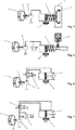
- FIGS. 4 to 7 show in a schematic representation of a clutch actuator according to the invention, as in a drive train or one of in FIG. 2 or FIG. 3 shown devices for power transmission and / or power distribution of the drive power can be used.
- the in the FIGS. 4 to 7 shown sliding sleeve 6 corresponds in function to the in FIG. 2 and FIG. 3 shown sliding sleeve 6 and is displaceable via a hydraulic actuator 7 from a connect position to a disconnect position (indicated by the double arrows below the sliding sleeve 7). It is also not hydraulically acting actuators are used.
- the hydraulic actuator 7 is supplied with a hydraulic pressure generated by a hydraulic pump 8 to displace the sliding sleeve 6 against the force of acting as a biasing member spring 9 from a connect position to a disconnect position and so perform a disengaging operation of the clutch.
- the hydraulic pump 8 constitutes a manipulated variable unit which provides a manipulated variable (here: hydraulic pressure) for generating a clutch disengaging force.
- a manipulated variable here: hydraulic pressure
- an electromagnetic clutch may be provided which drives a ramp mechanism.
- the hydraulic pump 8 (the manipulated variable unit of the coupling device) is connected via an operative connection 10 and an intermediate drive coupling 11 with a secondary drive member 5 in a power-transmitting operative connection.
- the secondary drive member to which the manipulated variable unit is operatively connected may be formed by any of the drive members of the 2-WD mode and 4-WD mode rotating portion of the secondary driveline, for example, the propeller shaft or an input or output shaft of the power transmission device and / or power distribution of the drive power.
- the drive coupling 11 is preferably a non-contact, on-demand switchable and preferably electrically controllable magnetic or eddy current coupling.
- the use of such a transferable torque limiting clutch has the advantage that - due to the non-contact running and the limited transmittable torque - also acts as a pressure limiter, as the pressure generated by the hydraulic pump is directly dependent on the torque transmitted to the hydraulic pump , Thus, when using such a drive coupling 11 can be dispensed with a pressure relief valve.
- the clutch is to be interpreted in terms of their torque transfer potential only such that the hydraulic pressure generated is sufficient to urge the sliding sleeve in a disconnect operation in the disconnect position.
- the power to be transmitted to the hydraulic pump via the drive coupling can be varied by appropriate control of the pump and, if necessary, reduced to zero.
- the arrangement described allows - apart from the respective switching operations - operating in both 4-WD or Connect mode as also in 2-WD or Disconnect mode without significant drag losses and without consumption of electrical energy.
- FIG. 4 described components and operations concern the disengaging unit or their function for the disconnect operation, the engagement process or the engaging operation of the components and processes will be described below.
- the acting as a biasing element spring 9 stores a large part of the introduced during the disengagement process in the system for the realization of the coupling process energy.
- the spring force will urge the sliding sleeve 6 from the disconnect position back into the connect position, but is held in the disconnect position by a magnetic retainer 12 acting as a retainer during operation in 2-WD mode.
- the magnet holder 12 is dimensioned such that its restraining force is greater than the oppositely acting spring force of the biasing member.
- the magnet holder 12 is electrically switchable has a current-carrying permanent magnet 13.
- the permanent magnet is electrically energized, thereby losing its magnetic power.
- the restraining force is thus canceled or reduced and the magnetic switch releases the restoring force of the biasing member 9 to initiate the connect operation.
- the connect mode there is an air gap (gap width for example> 2 mm) between the permanent magnet 13 and the component of the magnet holder 12 holding it in the disconnect mode, so that the permanent magnet is not pulled back into the disconnect position even when the current supply is switched off. becomes.
- a retaining device equipped with such a magnet holder allows for low current intensities (I ⁇ 2 A) a high retention force (F> 1000 N), according to current requirements, it is assumed that the magnet holder only has to be able to a spring force of the biasing element greater 300 N to keep safe. In addition, such a magnet holder has only a small space requirement.
- FIG. 5 shows a slight modification of the FIG. 4 shown embodiment, in which the drive coupling, which - as described above - also performs the function of a pressure limiter, is dispensed with. Consequently, part of the disengaging unit is also a pressure limiting valve 16 which does not allow the pressure generated by the hydraulic pump 8 to rise above a suitable maximum value.
- the pressure limiter in this driving mode is preferably adjusted to low pressure, preferably to zero.
- FIG. 5 an alternative embodiment of a retaining element in the form of a switching pawl 14, in which an electromagnetically actuated pawl engages in a latching groove and so is able to hold the sliding sleeve energy supply in the disconnect position.
- the switching latch 14 must be controlled in order to release the biasing force exerted by the biasing member 9 for the engagement process.
- FIG. 6 shows a variant of the invention, in which on a potential energy vorhaltendes biasing element 9, as shown in FIG. 4 and FIG. 5 is shown is omitted.
- a bi-stable retaining element 17 is used in the manner of a disc spring.
- Such a retaining element can be transferred, starting from a first, stable in itself position in a second, stable in itself position when it is suppressed against an internal resistance over an indifferently stable zero position addition.
- a total bi-stable Coupling device ensures that neither when operating the motor vehicle in 2-WD mode nor during its operation in 4-WD mode requires an energy supply to hold the respective coupling state. This is required only for the actual coupling process.
- a hydraulic pump 8 is provided, which can be brought into a power-transmitting operative connection via an intermediate and the transferable torque limiting drive clutch 11 with a secondary drive member 5 (possibly also with a primary drive member 4).
- the hydraulic pump 8 controls in the in FIG. 6 shown example, a double-acting hydraulic actuation and has a control valve 15 required for this purpose.
- FIG. 7 shows an embodiment of a system for controlling a coupling device, in which compared to the in FIG. 6 embodiment shown to a drive coupling 11, by means of which also can be limited to the transferable to the hydraulic pump 8 torque is dispensed with. Again, therefore, a pressure relief valve is provided which does not allow the pressure generated by the hydraulic pump 8 to rise above a suitable maximum value.
- the clutch actuating device When the clutch actuating device is embodied such that the disengaging unit is in operative connection with the secondary drive elements for the provision of the clutch actuating force required for the actuation of the clutch device, irrespective of whether this is achieved via a drive clutch 11 (FIG. FIG. 4 and FIG. 6 ) or without such a drive coupling ( FIG. 5 and FIG. 7 ) happens - can also be provided that the drive torque that is tapped via the operative connection of the secondary links to provide the manipulated variable for the clutch actuation force is used after the disengagement as a braking torque for the secondary drive elements.
- a high manipulated variable such as a high hydraulic pressure
- a high drive torque can be requested, after completion of the disengagement process acts as a braking torque.
- disconnect mode can be prevented.
Landscapes
- Engineering & Computer Science (AREA)
- Mechanical Engineering (AREA)
- Chemical & Material Sciences (AREA)
- Combustion & Propulsion (AREA)
- Transportation (AREA)
- General Engineering & Computer Science (AREA)
- Hydraulic Clutches, Magnetic Clutches, Fluid Clutches, And Fluid Joints (AREA)
- Arrangement And Driving Of Transmission Devices (AREA)
- Arrangement And Mounting Of Devices That Control Transmission Of Motive Force (AREA)
- Mechanical Operated Clutches (AREA)
Description
- Die Erfindung betrifft ein System zur Betätigung einer Kupplungsvorrichtung einer Einrichtung zur Leistungsübertragung und/oder Leistungsverteilung der Antriebsleistung eines Kraftfahrzeugs, insbesondere eines Automobils bzw. Personenkraftwagens, wobei die Einrichtung zur Leistungsübertragung und/oder Leistungsverteilung
- Primärantriebsglieder aufweist, die bei bestimmungsgemäßer Installation und Verwendung der Einrichtung zur Leistungsübertragung und/oder Leistungsverteilung am Kraftfahrzeug bei Fahrt permanent angetrieben oder geschleppt sind, und
- Sekundärantriebsglieder aufweist, die bei bestimmungsgemäßer Installation und Verwendung der Einrichtung zur Leistungsübertragung und/oder Leistungsverteilung am Kraftfahrzeug im Bedarfsfall mittels einer Kupplungsvorrichtung mit den Primärantriebsgliedern verkoppelt oder von den Primärantriebsgliedern entkoppelt werden können,
- Die Erfindung betrifft ferner eine Einrichtung zur Leistungsübertragung und/oder Leistungsverteilung der Antriebsleistung eines Kraftfahrzeugs mit einem solchen System zur Betätigung einer Kupplungsvorrichtung sowie ein Kraftfahrzeug mit einem eine derartige Einrichtung umfassenden Antriebsstrang.
- In jüngerer Zeit werden von Fahrzeugherstellern und Zulieferern zunehmend Antriebsstrangkonzepte mit zuschaltbarem Allradantrieb entwickelt. Derartige Antriebsstrangkonzepte, denen sich die Erfindung insbesondere widmet, weisen einen Primärantriebsstrang auf, über den die permanent angetriebene Primärachse und die hiermit verbundenen Primärantriebsräder angetrieben werden, sowie einen zuschaltbaren Sekundärantriebsstrang, der eine Sekundärachse mit Sekundärantriebsrädern umfasst und der im Bedarfsfall dem Primärantriebsstrang zugeschaltet (Einrückvorgang bzw. "Connect"-Vorgang) bzw. von diesem entkoppelt werden kann (Ausrückvorgang bzw. "Disconnect"-Vorgang).
- Bei zugeschaltetem Sekundärantriebsstrang wird die von dem Antriebsaggregat des Kraftfahrzeugs zur Verfügung gestellte Antriebsleistung mittels Einrichtungen zur Leistungsübertragung und/oder Leistungsverteilung, zum Beispiel mittels einer PTU (Power-Takeoff-Unit) und einer RDU (Rear-Drive-Unit), sowohl auf die Primärantriebsräder als auch auf die Sekundärantriebsräder verteilt (Betrieb des Fahrzeugs im 4-WD Modus oder "Connect"-Modus). Bei vom Primärantriebsstrang entkoppeltem Sekundärantriebsstrang werden hingegen nur die Primärantriebsräder angetrieben (Betrieb des Fahrzeugs im 2-WD Modus oder "Disconnect"-Modus). Die Sekundärantriebsräder rollen bei Fahrt auf der Straße ab, ohne zum Vortrieb beizutragen.
- Bei derartigen Antriebssträngen wird angestrebt, die Komponenten des Sekundärantriebsstrangs im 2-WD Modus möglichst umfassend sowohl von der Primärachse als auch von den bei Fahrt auf der Straße abrollenden Sekundärantriebsrädern zu entkoppeln, so dass bei dieser Betriebsart möglichst viele Komponenten des Sekundärantriebsstrangs weder vom Primärantriebsstrang noch von den Sekundärantriebsrädern geschleppt werden. Die von den Sekundärantriebsgliedern verursachte Verlustleistung wird so weitgehend minimiert. Die im 2-WD Modus stillgelegten Komponenten werden im Rahmen dieser Anmeldung als Sekundärantriebsglieder bezeichnet wohingegen die permanent rotierenden Komponenten des Gesamtantriebsstrangs einschließlich der Komponenten, die mit den auf der Straße abrollenden Sekundärantriebsrädern rotieren, als Primärantriebsglieder bezeichnet werden.
- Derartige Antriebsstrangkonzepte benötigen daher zum einen eine Kupplungsvorrichtung, die dazu dient, Sekundärantriebsstrangkomponenten mit dem permanent angetriebenen Primärantriebsstrang zu koppeln oder von diesem zu entkoppeln (Schnittstelle zum Primärantriebsstrang). Zum anderen ist eine Kupplungsvorrichtung vorzusehen, die die Sekundärantriebsstrangkomponenten mit den Sekundärantriebsrädern bzw. den von den Sekundärantriebsrädern durch Abrollen auf der Straße mitgeschleppten Komponenten des Sekundärantriebsstrangs verbindet bzw. wieder von diesen trennt (Schnittstelle zum Sekundärantriebsrad). Nur wenn derartige Kupplungsvorrichtungen vorgesehen sind, lässt sich ein Teil des Sekundärantriebsstrangs, nämlich der zwischen den beiden Kupplungsvorrichtungen bzw. Schnittstellen liegende Teil, vollständig stilllegen, da dieser bei Fahrt weder vom permanenten Primärantriebsstrang noch von den bei Fahrt auf der Straße abrollenden Sekundärantriebsrädern angetrieben bzw. geschleppt wird.
- Den Kupplungen sind Systeme zur Kupplungsbetätigung zugeordnet, welche den eigentlichen Kupplungsvorgang, also insbesondere das Ein- bzw. Ausrücken der Kupplung, durchführen. Die Einleitung eines Kupplungsvorgangs erfordert Energie, die im Zeitpunkt der Kupplungsbetätigung zur Verfügung stehen muss, um eine den Kupplungsvorgang durchführende Kupplungsbetätigungskraft bereitstellen zu können.
- Es ist bekannt, zur Kupplungsbetätigung Elektromotoren, elektromechanische oder elektromagnetisch betätigte Aktuatoren oder Hydraulikpumpen und hydraulisch betätigte Aktuatoren einzusetzen, die den Kupplungsmechanismus betätigen bzw. die für den Kupplungsvorgang benötigte Kupplungsbetätigungskraft aufbringen.
- Elektromotoren oder elektrisch betätigte Aktuatoren und gegebenenfalls die zu deren Versorgung und Steuerung erforderlichen Kabelbäume und Steuereinrichtungen haben ein verhältnismäßig hohes Gewicht, nehmen viel Bauraum ein und können - insbesondere wenn sie hohe Ströme ziehen - zu elektromagnetisch bedingten Störungen führen.
- Hydraulikpumpen müssen zur Erzeugung des für den Kupplungsvorgang erforderlichen Hydraulikdrucks angetrieben werden und verursachen so Verlustleistung.
- Ein gattungsgemässes System ist aus
DE102009005378 bekannt. - Aufgabe der Erfindung ist es, ein System zur Betätigung einer Kupplungsvorrichtung zur Verfügung zu stellen, das eine geringe Energieaufnahme erfordert, insbesondere mit geringerer Stromstärke als Elektromotoren oder elektrische Aktuatoren auskommt. Ferner soll die Kupplungsbetätigungseinrichtung ein geringes Risiko für elektromagnetische Störungen, ein geringes Gewicht und einen geringen Bauraumbedarf aufweisen. Sie soll in der Lage sein, die Kupplung spontan und mit geringer und von der Fahrzeuggeschwindigkeit unabhängiger Ansprechzeit zu betätigen sowie eine hohe Kupplungsbetätigungskraft zur Verfügung stellen. Die Konzeption soll derart sein, dass sie für eine Vielzahl verschiedener Kupplungsvarianten einsetzbar ist.
- Die Erfindung sieht hierzu unter anderem vor, dass die Ausrückeinheit zur Bereitstellung der für die Betätigung der Kupplungsvorrichtung erforderlichen Kupplungsbetätigungskraft mit den Sekundärantriebsgliedern in Wirkverbindung steht. Alternativ oder zusätzlich hierzu kann vorgesehen sein, dass eine Antriebskupplung vorgesehen ist, die zur Bereitstellung der für die Betätigung der Kupplungsvorrichtung erforderlichen Kupplungsbetätigungskraft eine Wirkverbindung zwischen den Primärantriebsgliedern oder den Sekundärantriebsgliedern einerseits und der Ausrückeinheit andererseits herzustellen vermag.
- In beiden vorgenannten Fällen ist dafür gesorgt, dass die Ausrückeinheit, die insbesondere eine für den Kupplungsvorgang anzutreibende Hydraulikpumpe umfassen kann, keine dauernde Verlustleistung verursacht, wenn die Sekundärantriebsglieder von der Primärachse und den Sekundärantriebsrädern entkoppelt sind und bestimmungsgemäß still stehen.
- Steht die Ausrückeinheit mit den Sekundärantriebsgliedern in Wirkverbindung und sind die Sekundärantriebsglieder im 2-WD Modus stillgelegt, kann die Ausrückeinheit zur Erzeugung einer Kupplungsbetätigungskraft keine Leistung von den still stehenden Sekundärantriebsgliedern abgreifen. Die Komponenten der Ausrückeinheit, etwa die bereits angesprochene Hydraulikpumpe, laufen nicht mit, sondern stehen ebenfalls still und verursachen keinerlei Verlustleistung.
- Bei Verwendung einer Antriebskupplung zur Herstellung einer Wirkverbindung zwischen Sekundär- oder Primärantriebsgliedern einerseits und Ausrückeinheit andererseits sind die Kupplungsbetätigungseinrichtung bzw. deren Komponenten ebenfalls stillgelegt und verursachen keine Verlustleistung. Für den Fall, dass die Antriebskupplung zwischen bei Fahrt permanent rotierenden Primärantriebsgliedern und Kupplungsbetätigungseinrichtung angeordnet ist, gilt dies selbstverständlich nur bei geöffneter Antriebskupplung. Bei zwischen Sekundärantriebsgliedern und Ausrückeinheit angeordneter Antriebskupplung entsteht der zusätzliche Vorteil, dass die Kupplungsbetätigungseinrichtung selbst im 4-WD Modus und trotz mitrotierender Sekundärantriebsglieder keine Verlustleistung verursacht, solange die Antriebskupplung nicht angesteuert ist und somit kein Drehmoment überträgt.
- Die Kupplungsvorrichtung zum Verkoppeln bzw. Entkoppeln von den Primär- und Sekundärantriebsgliedern ist bevorzugt eine formschlüssig wirkende Kupplung (auch als Dog-Clutch bezeichnet), insbesondere eine Klauenkupplung oder eine Kupplung mit einer Primär- und Sekundärantriebsglieder formschlüssig verbindenden Schiebemuffe, die zwischen einer Connect-Position, in der die Primär- und Sekundärantriebsglieder formschlüssig miteinander verbunden sind, und einer Disconnect-Position, in der die Primär- und Sekundärantriebsglieder voneinander getrennt sind, hin und her bewegbar ist.
- Bei der Antriebskupplung handelt es sich bevorzugt um eine On-Demand schaltbare Antriebskupplung. Um zu gewährleisten, dass die Antriebskupplung selbst keine oder nur vernachlässigbare Verlustleistung verursacht, kann insbesondere eine berührungsfrei arbeitende Kupplung vorgesehen sein. Hierbei kann es sich bevorzugt um eine berührungsfrei arbeitende Magnetkupplung handeln. Ein weiteres Beispiel für eine derartige Antriebskupplung ist eine Wirbelstromkupplung.
- Der Einsatz einer derartigen berührungslos arbeitenden und bevorzugt elektrisch ansteuerbaren Kupplung kann auch deshalb als besonders vorteilhaft angesehen werden, weil das von einer derartigen Kupplung gewährleistete Drehmomentübertragungspotential begrenzt ist. Eine derartige Antriebskupplung kann so zum Beispiel bei Einsatz einer Hydraulikpumpe zur Bereitstellung eines die Kupplungsbetätigungskraft gewährleistenden Hydraulikdrucks effektiv als Druckbegrenzer oder Überlastschutz eingesetzt werden. Ferner ermöglicht eine derartige Kupplung eine effektive Druckbegrenzung in beiden Fahrrichtungen bzw. Rotationsrichtungen der Kupplungsglieder.
- Zudem ist das Drehmomentübertragungspotential einer derartigen Antriebskupplung von der Bestromung der Kupplung abhängig und ist somit durch eine gezielte Bestromung gezielt einstellbar. Durch die Einstellung des Drehmomentübertragungspotentials über den der Kupplung zugeführten Strom lässt sich somit das auf die Ausrückeinheit übertragbare und die Höhe der Kupplungsbetätigungskraft bestimmende Drehmoment nicht nur effektiv begrenzen, sondern bei Bedarf auch gezielt einregeln. Die Kupplungsbetätigungskraft und die Geschwindigkeit des Druckaufbaus und somit auch die Schnelligkeit des Einrück- bzw. Ausrückvorgangs können gezielt beeinflusst werden. Auch ist ein nahtloses, ruckfreies Ein- und Auskuppeln möglich.
- Für den Einrückvorgang weist die Kupplungsbetätigungseinrichtung bevorzugt neben der Ausrückeinheit auch eine Einrückeinheit auf. Die Einrückeinheit gewährleistet das Einrücken der Kupplungsvorrichtung und damit das Zuschalten des im 2-WD bzw. Disconnect-Modus stillgelegten Teils des Sekundärantriebsstrangs zur Primärachse und zu den im von den Sekundärantriebsrädern geschleppten Komponenten zu den Primärantriebsgliedern.
- Die Einrückeinheit weist bevorzugt ein für den Einrückvorgang potentielle Energie vorhaltendes Vorspannelement auf. Dieses gewährleistet, dass die für den Einrückvorgang benötigte Kupplungskraft durchgängig bereitgehalten ist. Als Vorspannelement kommt insbesondere ein Federelement in Betracht.
- Um das Vorspannelement insbesondere auch dann auf Spannung (in einer die potentielle Energie bereithaltenden Position) zu halten, wenn die Kupplungsvorrichtung nicht mit einem rotierenden Teil des Antriebsstrangs in Wirkverbindung steht und daher keine Kupplungsbetätigungskraft neu generieren kann, kann die Ausrückeinheit ein Rückhalteelement aufweisen, das die Kupplung mittels einer Rückhaltekraft während des Betriebs des Fahrzeugs im 2-WD Modus in ausgerückter Position (Disconnect-Position) hält.
- Das Rückhalteelement ist dabei bevorzugt derart ausgebildet, dass es die Kupplungsvorrichtung während des Betriebs des Fahrzeugs im 2-WD Modus ohne andauernde Energiezufuhr und somit dauerhaft verlustleistungsfrei in der Disconnect-Position zu halten vermag und es aktiv angesteuert werden muss, beispielsweise bestromt oder auf sonstige Weise aktiviert werden muss, wenn es die im Vorspannelement gespeicherte Energie zur Initiierung des Einrückvorgangs durch Aufgabe der Rückhaltekraft freigeben soll. Energie wird daher nur für den eigentlichen Kupplungsvorgang, also das Ein- bzw. Ausrücken benötigt, nicht aber für das Halten des Kupplungszustands im Connect- bzw. Disconnect-Modus. Als Rückhaltevorrichtung kommt insbesondere ein elektrisch ansteuerbarer Magnethalter mit einem Dauermagneten in Betracht.
- Die vorstehend beschriebene Ausgestaltung der Einrückeinheit gewährleistet zudem die Initiierung und Durchführung des Einrückvorgangs unabhängig von der zur Verfügung stehenden "Energiedichte" des gerade vorherrschenden Fahrzustands, also insbesondere unabhängig von der Fahrzeuggeschwindigkeit, da die vom Vorspannelement bereitgehaltene potentielle Energie fahrzustandsunabhängig konstant ist. Der Fahrer empfindet den Einrückvorgang daher fahrzustandsunabhängig stets als gleich schnell ablaufend, unabhängig davon, wie schnell er gerade fährt.
- Weiter gewährleistet die vorstehende Ausgestaltung, dass das System zur Betätigung einer Kupplungsvorrichtung bi-stabil ausgeführt sein kann. Dies bedeutet, dass weder zum dauerhaften Halten des 2-WD bzw. Disconnet-Modus noch zum dauerhaften Halten des 4-WD bzw. Connect-Modus Energie aufgebracht werden muss, sondern die jeweiligen Zustände energiezuführungsfrei gehalten werden. Lediglich zur Initiierung und Durchführung eines Ein- oder Ausrückvorgangs ist das Bereitstellen von Energie zur Erzeugung einer Kupplungsbetätigungskraft erforderlich.
- Es sei angemerkt, dass die Einrückeinheit und die Ausrückeinheit keine vollständig voneinander getrennten Vorrichtungen sein müssen. Vielmehr können sich beide Einheiten auch Komponenten und deren Funktionen teilen.
- Weitere Merkmale und Vorteile der Erfindung ergeben sich aus den Unteransprüchen und aus der nachfolgenden Beschreibung bevorzugter Ausführungsbeispiele anhand der Zeichnungen.
- In den Zeichnungen zeigt
- Fig. 1
- in schematischer Darstellung einen Gesamtantriebsstrang eines Kraftfahrzeugs gemäß dem Stand der Technik mit permanent angetriebenem Primärantriebsstrang und mit einem bei Bedarf dem Primärantriebsstrang zuschaltbaren oder von diesem entkoppelbaren Sekundärantriebsstrang,
- Fig. 2
- eine PTU (Power-Takeoff-Unit) gemäß dem Stand der Technik und wie sie bei dem in
Figur 1 gezeigten Antriebsstrang zum Einsatz kommen kann, - Fig. 3
- eine RDU (Rear-Drive-Unit) gemäß dem Stand der Technik und sie bei dem in
Figur 1 gezeigten Antriebsstrang zum Einsatz kommen kann, - Fig. 4
- eine bi-stabile Kupplungsbetätigungseinrichtung in schematischer Darstellung mit einer Ausrückeinheit und einer Einrückeinheit und einer zwischen einem Primär- oder Sekundärantriebsglied und einer Stellgrößeneinheit wirkenden Antriebskupplung,
- Fig. 5
- eine Abwandlung der in
Figur 4 gezeigten Ausführungsform in schematischer Darstellung mit einer direkten Verbindung zwischen Sekundärantriebsglied und Stellgrößeneinheit sowie mit einem zusätzlichen Druckbegrenzungsventil, - Fig. 6
- eine bi-stabile Kupplungsbetätigungseinrichtung in schematischer Darstellung mit einem zweifach wirkenden Kupplungsaktuator und einem bi-stabilen Rückhalteelement und einer zwischen einem Primär- oder Sekundärantriebsglied und einer Stellgrößeneinheit wirkenden Antriebskupplung, und
- Fig. 7
- eine Abwandlung der in
Figur 6 gezeigten Ausführungsform in schematischer Darstellung mit einer direkten Verbindung zwischen Sekundärantriebsglied und Stellgrößeneinheit sowie mit einem zusätzlichen Druckbegrenzungsventil. - In
Figur 1 ist ein aus dem Stand der Technik bekannter Antriebsstrangaufbau mit permanent angetriebenem Primärantriebsstrang - inFigur 1 beispielhaft der von einem Frontmotor permanent angetriebene und die Antriebsleistung auf die Vorderräder leitende Teil des Gesamtantriebstrangs - und einem nur im Bedarfsfall angetriebenen Sekundärantriebsstrang, über den die Antriebsleistung im Bedarfsfall auch zu den Sekundärantriebsrädern geleitet wird, gezeigt. Selbstverständlich sind auch andere Antriebsstrangkonfigurationen, bei denen die primär angetriebene Achse zum Beispiel die Hinterachse ist und/oder bei der ein Heck- oder Mittelmotor zum Einsatz kommt, denkbar. - Im 4-WD bzw. Connect-Modus wird über eine PTU 1, die im Detail in
Figur 2 gezeigt ist, Antriebsleistung am Primärantriebsstrang abgegriffen und über eine Kardanwelle zu einer RDU 2, die im Detail inFigur 3 gezeigt ist, weitergeleitet, welche die Aufgabe eines Querausgleichs übernimmt und die Antriebsleistung auf die beiden Sekundärantriebsräder überträgt. PTU und RDU stellen jeweils eine Einrichtung zur Leistungsübertragung und/oder Leistungsverteilung der Antriebsleistung im Sinne der Erfindung dar. - Sowohl an der PTU 1 als auch an der RDU 2 ist jeweils eine formschlüssig wirkende Kupplungsvorrichtung 3 vorgesehen, mit der Primärantriebsglieder 4 und Sekundärantriebsglieder 5 der PTU bzw. der RDU miteinander verkoppelt oder voneinander entkoppelt werden können. Eine hydraulische Aktuierung 7 verschiebt als Teil einer Ausrückeinheit der Kupplungsbetätigungseinrichtung hierzu eine Schiebemuffe 6 zwischen einer Connect-Position (Primär- und Sekundärantriebsglieder sind miteinander verkoppelt) und einer Disconnect-Position (Primär- und Sekundärantriebsglieder sind voneinander entkoppelt).
-
Figuren 4 bis 7 zeigen in einer schematischen Darstellung eine Kupplungsbetätigungseinrichtung gemäß der Erfindung, wie sie bei einem Antriebsstrang bzw. einer der inFigur 2 oder Figur 3 gezeigten Einrichtungen zur Leistungsübertragung und/oder Leistungsverteilung der Antriebsleistung zum Einsatz kommen kann. Die in denFiguren 4 bis 7 gezeigte Schiebemuffe 6 entspricht in ihrer Funktion der inFigur 2 und Figur 3 gezeigten Schiebemuffe 6 und ist über eine hydraulische Aktuierung 7 von einer Connect-Position in eine Disconnect-Position verschiebbar (angedeutet durch die Doppelpfeile unterhalb der Schiebemuffe 7). Es können auch nicht hydraulisch wirkende Aktuierungen zum Einsatz kommen. - Die hydraulische Aktuierung 7 wird mit einem von einer Hydraulikpumpe 8 erzeugten Hydraulikdruck versorgt, um die Schiebemuffe 6 gegen die Kraft einer als Vorspannelement fungierenden Feder 9 von einer Connect-Position in eine Disconnect-Position zu verlagern und so einen Ausrückvorgang der Kupplung zu vollziehen. Die Hydraulikpumpe 8 stellt als Teil einer Ausrückeinheit eine Stellgrößeneinheit dar, die eine zur Erzeugung einer Kupplungsausrückkraft dienende Stellgröße (hier: hydraulischen Druck) bereitstellt. Für die Erfindung ist selbstverständlich grundsätzlich auch die Verwendung andersartiger anderer Stellgrößeneinheiten, die andersartige Stellgrößen bereitstellen, denkbar. Insbesondere kann anstelle einer durch eine Antriebskupplung angetriebenen Hydraulikpumpe eine elektromagnetische Kupplung vorgesehen sein, die einen Rampenmechanismus antreibt.
- Die Hydraulikpumpe 8 (die Stellgrößeneinheit der Kupplungsvorrichtung) steht über eine Wirkverbindung 10 und eine zwischengeschaltete Antriebskupplung 11 mit einem Sekundärantriebsglied 5 in leistungsübertragender Wirkverbindung. Das Sekundärantriebsglied, mit dem die Stellgrößeneinheit in Wirkverbindung steht, kann von jedem beliebigen Antriebsglied des im 2-WD Modus stillgelegten und im 4-WD Modus rotierenden Teils des Sekundärantriebsstrangs gebildet sein, beispielsweise von der Kardanwelle oder einer Eingangs- oder Ausgangswelle der Einrichtung zur Leistungsübertragung und/oder Leistungsverteilung der Antriebsleistung.
- Die Antriebskupplung 11 ist bevorzugt eine berührungslos arbeitende, On-Demand schaltbare und bevorzugt elektrisch regelbare Magnet- oder Wirbelstromkupplung. Die Verwendung einer solchen das übertragbare Drehmoment begrenzenden Kupplung hat den Vorteil, dass diese - bedingt durch den berührungsfreien Lauf und das nur begrenzt übertragbare Drehmoment - auch als Druckbegrenzer fungiert, da der von der Hydraulikpumpe erzeugte Druck direkt abhängig von dem auf die Hydraulikpumpe übertragenen Drehmoment ist. Somit kann bei der Verwendung einer derartigen Antriebskupplung 11 auf ein Druckbegrenzungsventil verzichtet werden. Die Kupplung ist in Bezug auf ihr Drehmomentübertragungspotential lediglich derart auszulegen, dass der erzeugte Hydraulikdruck ausreicht, die Schiebemuffe bei einem Disconnect-Vorgang in die Disconnect-Position zu drängen. Ferner kann die über die Antriebskupplung auf die Hydraulikpumpe zu übertragende Leistung durch entsprechende Ansteuerung der Pumpe variiert werden und bei Bedarf bis auf Null reduziert werden.
- Die beschriebene Anordnung ermöglicht - von den jeweiligen Schaltvorgängen abgesehen - einen Betrieb sowohl im 4-WD bzw. Connect-Modus als auch im 2-WD bzw. Disconnect Modus ohne nennenswerte Schleppverluste und ohne Verbrauch elektrischer Energie.
- Während die vorstehend zu
Figur 4 beschriebenen Komponenten und Vorgänge die Ausrückeinheit bzw. deren Funktion für den Disconnect-Vorgang betreffen, wird nachfolgend der Einrückvorgang bzw. die den Einrückvorgang betreffenden Komponenten und Vorgänge beschrieben. - Die als Vorspannelement fungierende Feder 9 speichert einen großen Teil der beim Ausrückvorgang in das System zur Realisierung des Kupplungsvorgangs eingebrachten Energie. Die Federkraft will die Schiebemuffe 6 aus der Disconnect-Position zurück in die Connect-Position drängen, wird aber durch einen als Rückhalteelement fungierenden Magnethalter 12 während des Betriebs im 2-WD Modus in der Disconnect-Position gehalten. Der Magnethalter 12 ist derart dimensioniert, dass dessen Rückhaltekraft größer ist als die entgegengesetzt wirkende Federkraft des Vorspannelements.
- Der Magnethalter 12 ist elektrisch schaltbar weist einen bestrombaren Dauermagneten 13 auf. Um den Connect-Vorgang auszulösen, wird der Dauermagnet elektrisch angesteuert, wodurch er seine magnetische Kraft einbüßt. Die Rückhaltekraft wird so aufgehoben oder verringert sich und der Magnetschalter gibt die Rückstellkraft des Vorspannelements 9 frei, um den Connect-Vorgang auszulösen. Im Connect-Modus besteht zwischen dem Dauermagneten 13 und der diesen im Disconnect-Modus haltenden Komponente des Magnethalters 12 ein Luftspalt (Spaltweite zum Beispiel > 2 mm), dass auch bei Ausschalten der Bestromung der Dauermagnet nicht zurück in die Disconnect-Position "gezogen" wird.
- Eine mit einem derartigen Magnethalter ausgestattete Rückhaltevorrichtung ermöglicht bei geringen Stromstärken (I < 2 A) eine hohe Rückhaltekraft (F > 1000 N), wobei nach derzeitigen Anforderungen davon auszugehen ist, dass der Magnethalter lediglich in der Lage sein muss, eine Federkraft des Vorspannelements größer 300 N sicher zu halten. Zudem hat ein derartiger Magnethalter nur einen geringen Bauraumbedarf.
- Es sei erwähnt, dass bei Verwendung der in
Figur 4 gezeigten, grundverlustfrei arbeitenden Antriebskupplung 11 auch eine leistungsübertragende Wirkverbindung der Ausrückeinheit mit den Primärantriebsgliedern 4 möglich ist, da auch in diesem Fall etwaige Schleppverluste vermieden werden. -
Figur 5 zeigt eine leichte Abwandlung der inFigur 4 gezeigten Ausführungsform, bei der auf die Antriebskupplung, die - wie vorstehend beschrieben - auch die Funktion eines Druckbegrenzers wahrnimmt, verzichtet ist. Folglich ist Teil der Ausrückeinheit auch ein Druckbegrenzungsventil 16, das den von der Hydraulikpumpe 8 erzeugten Druck nicht über einen geeigneten Maximalwert ansteigen lässt. Um im Connect-Modus die Verlustleistung so gering wie möglich zu halten, wird der Druckbegrenzer in diesem Fahrmodus bevorzugt auf niedrigen Druck, bevorzugt auf Null, eingeregelt. - Ferner zeigt
Figur 5 eine alternative Ausführungsform eines Rückhalteelements in Form einer Schaltraste 14, bei der eine elektromagnetisch aktuierte Sperrklinke in eine Rastnut eingreift und so die Schiebemuffe energiezuführungsfrei in der Disconnect-Position zu halten vermag. Auch hier ist vorgesehen, dass die Schaltraste 14 angesteuert werden muss, um die von dem Vorspannelement 9 ausgeübte Vorspannkraft für den Einrückvorgang freizugeben. - Selbstverständlich kann die Schaltraste 14 auch bei der in
Figur 4 gezeigten Ausführungsform anstelle des dort dargestellten Magnetschalters 12 zum Einsatz kommen und umgekehrt. -
Figur 6 zeigt eine Variante der Erfindung, bei der auf ein potentielle Energie vorhaltendes Vorspannelement 9, wie es inFigur 4 und Figur 5 gezeigt ist, verzichtet ist. Stattdessen kommt ein bi-stabiles Rückhalteelement 17 nach Art einer Tellerfeder zum Einsatz. Ein derartiges Rückhalteelement kann ausgehend von einer ersten, in sich stabilen Lage in eine zweite, in sich stabile Lage überführt werden, wenn es gegen einen inneren Widerstand über eine indifferent stabile Nulllage hinaus überdrückt wird. Somit ist auch bei der Verwendung eines derartigen Rückhalteelements eine insgesamt bi-stabile Kupplungsvorrichtung gewährleistet, die weder bei Betrieb des Kraftfahrzeugs im 2-WD Modus noch bei dessen Betrieb im 4-WD Modus einer Energiezufuhr zum Halten des jeweiligen Kupplungszustandes bedarf. Diese ist nur für den eigentlichen Kupplungsvorgang erforderlich. - Zur Ansteuerung einer hydraulischen Aktuierung ist wiederum eine Hydraulikpumpe 8 vorgesehen, die über eine zwischengeschaltete und das übertragbare Drehmoment begrenzende Antriebskupplung 11 mit einem Sekundärantriebsglied 5 (ggf. auch mit einem Primärantriebsglied 4) in leistungsübertragender Wirkverbindung gebracht werden kann. Die Hydraulikpumpe 8 steuert in dem in
Figur 6 gezeigten Beispiel eine zweifach wirkende hydraulische Aktuierung an und weist ein hierfür erforderliches Steuerventil 15 auf. -
Figur 7 zeigt schließlich eine Ausführungsform eines Systems zur Ansteuerung einer Kupplungsvorrichtung, bei der gegenüber der inFigur 6 gezeigten Ausführungsform auf eine Antriebskupplung 11, mittels der auch das auf die Hydraulikpumpe 8 übertragbare Drehmoment begrenzt werden kann, verzichtet ist. Auch hier ist daher ein Druckbegrenzungsventil vorgesehen, das den von der Hydraulikpumpe 8 erzeugten Druck nicht über einen geeigneten Maximalwert ansteigen lässt. - Wenn die die Kupplungsbetätigungseinrichtung derart ausgebildet ist, dass die Ausrückeinheit für die Bereitstellung der für die Betätigung der Kupplungsvorrichtung erforderlichen Kupplungsbetätigungskraft mit den Sekundärantriebsgliedern in Wirkverbindung steht - unabhängig davon, ob dies über eine Antriebskupplung 11 (
Figur 4 und Figur 6 ) oder ohne eine derartige Antriebskupplung (Figur 5 und Figur 7 ) geschieht - kann außerdem vorgesehen sein, dass das Antriebsmoment, dass über die Wirkverbindung von den Sekundärgliedern zur Bereitstellung der Stellgröße für die Kupplungsbetätigungskraft abgegriffen wird, nach dem Ausrückvorgang als Bremsmoment für die Sekundärantriebsglieder eingesetzt ist. Insbesondere kann durch Einstellung einer hohen Stellgröße (etwa eines hohen Hydraulikdrucks) ein hohes Antriebsmoment angefordert werden, das nach Vollzug des Ausrückvorgangs als Bremsmoment wirkt. So kann selbst ein verlangsamtes Weiterrotieren der Sekundärantriebsglieder, das etwa aufgrund von hydrodynamischen Effekten in Lamellenkupplungen auftreten kann, Disconnect-Modus unterbunden werden. - Die Verwendung eines elektrisch ansteuerbaren Magnetschalters als Rückhalteelement und Bestandteil einer Kupplungsbetätigungseinrichtung, insbesondere als Bestandteil einer Einrückeinheit einer Kupplungsbetätigungseinrichtung, wird losgelöst von den Merkmalen der vorstehend beschriebenen Ausrückeinheit als eigenständige, gesondert beanspruchbare Erfindung angesehen.
-
- 1
- Power-Takeoff-Unit (PTU)
- 2
- Rear-Drive-Unit (RDU)
- 3
- Kupplungsvorrichtung
- 4
- Primärantriebsglieder
- 5
- Sekundärantriebsglieder
- 6
- Schiebemuffe (Eingriffsglied)
- 7
- hydraulische Aktuierung
- 8
- Stellgrößeneinheit (Hydraulikpumpe)
- 9
- Vorspannelement (Federelement)
- 10
- Wirkverbindung
- 11
- Antriebskupplung
- 12
- Rückhalteelement (Magnethalter)
- 13
- Dauermagnet
- 14
- Rückhalteelement (Schaltraste)
- 15
- Steuerventil
- 16
- Druckbegrenzungsventil
- 17
- Bi-stabiles Rückhalteelement
Claims (14)
- System zur Betätigung einer Kupplungsvorrichtung einer Einrichtung (1, 2) zur Leistungsübertragung und/oder Leistungsverteilung der Antriebsleistung eines Kraftfahrzeugs mit einem permanent angetriebenen Primärantriebsstrang und einem dem Primärantriebsstrang zuschaltbaren Sekundärantriebsstrang, wobei die Einrichtung zur Leistungsübertragung und/oder Leistungsverteilung (1, 2)- Primärantriebsglieder (4) aufweist, die bei bestimmungsgemäßer Installation der Einrichtung (1, 2) zur Leistungsübertragung und/oder Leistungsverteilung am Kraftfahrzeug bei Fahrt permanent angetrieben oder geschleppt sind, und- Sekundärantriebsglieder (5) aufweist, die bei bestimmungsgemäßer Installation der Einrichtung (1, 2) zur Leistungsübertragung und/oder Leistungsverteilung am Kraftfahrzeug im Bedarfsfall mittels einer Kupplungsvorrichtung (3) mit den Primärantriebsgliedern (4) verkoppelt oder von den Primärantriebsgliedern (4) entkoppelt werden können,und wobei die Kupplungsvorrichtung (3) eine Kupplungsbetätigungseinrichtung mit einer Ausrückeinheit zur Entkopplung von Primärantriebsgliedern (4) und Sekundärantriebsgliedern (5) aufweist,
dadurch gekennzeichnet, dass
das System derart eingerichtet ist, dass die Ausrückeinheit für die Bereitstellung der für die Betätigung der Kupplungsvorrichtung (3) erforderlichen Kupplungsbetätigungskraft mit den Sekundärantriebsgliedern (5) in Wirkverbindung steht. - System nach dem Oberbegriff des Anspruchs 1, dadurch gekennzeichnet, dass eine Antriebskupplung (11) vorgesehen ist, die für die Bereitstellung der für die Betätigung der Kupplungsvorrichtung (3) erforderlichen Kupplungsbetätigungskraft eine Wirkverbindung zwischen den Primärantriebsgliedern (4) oder den Sekundärantriebsgliedern (5) und einer Stellgrößeneinheit (8) der Ausrückeinheit herzustellen vermag.
- System nach einem der beiden vorhergehenden Ansprüche, dadurch gekennzeichnet, dass die Kupplungsvorrichtung (3) eine formschlüssig wirkende Kupplung ist.
- System nach Anspruch 2, dadurch gekennzeichnet, dass die Antriebskupplung (11) eine On-Demand schaltbare und elektrisch ansteuerbare Kupplung ist.
- System nach Anspruch 2 oder einem der Ansprüche 3 oder 4, sofern auf Anspruch 2 rückbezogen, dadurch gekennzeichnet, dass die Antriebskupplung (11) eine berührungsfrei arbeitende Kupplung ist.
- System nach Anspruch 2 oder einem der Ansprüche 3 oder 5, sofern auf Anspruch 2 rückbezogen, dadurch gekennzeichnet, dass die Antriebskupplung (11) eine Magnetkupplung oder eine Wirbelstromkupplung ist.
- System nach Anspruch 2 oder einem der Ansprüche 3 oder 6, sofern auf Anspruch 2 rückbezogen, dadurch gekennzeichnet, dass die Antriebskupplung (11) als Druckbegrenzungseinrichtung für eine Hydraulikdruck erzeugende Stellgrößeneinheit (8) fungiert.
- System nach einem der vorhergehenden Ansprüche, dadurch gekennzeichnet, dass eine Einrückeinheit vorgesehen ist, die ein für den Einrückvorgang potentielle Energie vorhaltendes Vorspannelement (9) aufweist.
- System nach einem der vorhergehenden Ansprüche, dadurch gekennzeichnet, dass die Kupplungsvorrichtung (3) eine Rückhalteelement (12, 14, 17) umfasst, das ein den Formschluss der Kupplung herstellendes Eingriffsglied (6) in dauerhaft ausgerückter Position zu halten vermag.
- System nach einem der vorhergehenden Ansprüche, dadurch gekennzeichnet, dass die Kupplungsvorrichtung (3) als bi-stabile Kupplungsvorrichtung ausgebildet ist.
- System nach einem der beiden vorhergehenden Ansprüche, dadurch gekennzeichnet, dass das Rückhalteelement von einem elektrisch ansteuerbaren Magnethalter (12) oder einer elektrisch ansteuerbaren Schaltraste (14) gebildet ist.
- System nach einem der vorhergehenden Ansprüche, dadurch gekennzeichnet, dass das Rückhalteelement (12, 14, 17) derart eingerichtet ist, dass bei Betrieb des Kraftfahrzeugs mit ausgerückter oder mit eingerückter Kupplung der jeweilige Schaltzustand der Kupplungsvorrichtung dauerhaft energiezuführungsfrei gehalten werden kann.
- System nach Anspruch 9, 10 oder 12, dadurch gekennzeichnet, dass ein bi-stabiles Rückhalteelement (17) vorgesehen ist, das ausgehend von einer ersten, in sich stabilen Lage in eine zweite, in sich stabile Lage überführt werden kann, wenn es gegen einen inneren Widerstand über eine indifferent stabile Nulllage hinaus überdrückt wird.
- Einrichtung zur Leistungsübertragung und/oder Leistungsverteilung der Antriebsleistung eines Kraftfahrzeugs mit einem System zur Betätigung einer Kupplungsvorrichtung nach einem der vorhergehenden Ansprüche.
Applications Claiming Priority (1)
| Application Number | Priority Date | Filing Date | Title |
|---|---|---|---|
| PCT/EP2015/069021 WO2017028913A1 (de) | 2015-08-19 | 2015-08-19 | System zur betätigung einer kupplung |
Publications (2)
| Publication Number | Publication Date |
|---|---|
| EP3337684A1 EP3337684A1 (de) | 2018-06-27 |
| EP3337684B1 true EP3337684B1 (de) | 2019-07-10 |
Family
ID=53887121
Family Applications (1)
| Application Number | Title | Priority Date | Filing Date |
|---|---|---|---|
| EP15753027.0A Active EP3337684B1 (de) | 2015-08-19 | 2015-08-19 | System zur betätigung einer kupplung |
Country Status (5)
| Country | Link |
|---|---|
| US (1) | US20180215259A1 (de) |
| EP (1) | EP3337684B1 (de) |
| JP (1) | JP2018523799A (de) |
| CN (1) | CN108025640A (de) |
| WO (1) | WO2017028913A1 (de) |
Families Citing this family (2)
| Publication number | Priority date | Publication date | Assignee | Title |
|---|---|---|---|---|
| DE102019107710A1 (de) * | 2019-03-26 | 2020-10-01 | Gkn Automotive Ltd. | Schaltvorrichtung für ein Kraftübertragungselement eines Kraftfahrzeugs |
| DE102021209252A1 (de) | 2021-08-24 | 2023-03-02 | Zf Friedrichshafen Ag | Kopplungsvorrichtung für ein Kraftfahrzeug |
Family Cites Families (9)
| Publication number | Priority date | Publication date | Assignee | Title |
|---|---|---|---|---|
| JPH01107635U (de) * | 1988-01-13 | 1989-07-20 | ||
| JPH0337379A (ja) * | 1989-06-30 | 1991-02-18 | Matsushita Electric Ind Co Ltd | 圧縮機の駆動装置 |
| US7549941B2 (en) * | 2005-09-09 | 2009-06-23 | Eaton Corporation | Vehicle differential including pump with variable-engagement clutch |
| DE102009005378C5 (de) * | 2008-10-13 | 2018-06-21 | Magna powertrain gmbh & co kg | Antriebsstrang für ein Kraftfahrzeug |
| KR101633143B1 (ko) * | 2009-01-21 | 2016-06-23 | 마그나 파워트레인 오브 아메리카, 인크. | 연결해제 시스템을 갖는 awd 차량 |
| US9371869B2 (en) * | 2011-03-15 | 2016-06-21 | GKN Driveline Japan Ltd. | Power transmission apparatus |
| JP2012218573A (ja) * | 2011-04-08 | 2012-11-12 | Gkn Driveline Japan Ltd | 動力伝達装置 |
| EP2701936B1 (de) * | 2011-04-28 | 2020-03-11 | Jaguar Land Rover Limited | Fahrzeug und verfahren zum steuern eines fahrzeugs, kraftübertragungseinheit und verfahren zum steuern einer kraftübertragungseinheit |
| WO2013038446A1 (ja) * | 2011-09-14 | 2013-03-21 | トヨタ自動車株式会社 | 動力断続装置 |
-
2015
- 2015-08-19 WO PCT/EP2015/069021 patent/WO2017028913A1/de not_active Ceased
- 2015-08-19 CN CN201580082511.5A patent/CN108025640A/zh active Pending
- 2015-08-19 US US15/748,656 patent/US20180215259A1/en not_active Abandoned
- 2015-08-19 JP JP2018509498A patent/JP2018523799A/ja active Pending
- 2015-08-19 EP EP15753027.0A patent/EP3337684B1/de active Active
Non-Patent Citations (1)
| Title |
|---|
| None * |
Also Published As
| Publication number | Publication date |
|---|---|
| US20180215259A1 (en) | 2018-08-02 |
| EP3337684A1 (de) | 2018-06-27 |
| WO2017028913A1 (de) | 2017-02-23 |
| CN108025640A (zh) | 2018-05-11 |
| JP2018523799A (ja) | 2018-08-23 |
Similar Documents
| Publication | Publication Date | Title |
|---|---|---|
| DE112013005384T5 (de) | Direktantriebsgetriebeentkoppler | |
| DE102020202651A1 (de) | Getriebekupplungsbremssteuersystem | |
| DE102009005378B4 (de) | Antriebsstrang für ein Kraftfahrzeug | |
| DE102011007577A1 (de) | Leistungsverzweigter hybrider Antriebsstrang mit mehreren Modi | |
| EP2757005A2 (de) | Verfahren zum Halten eines Kraftfahrzeuges an einer Steigung | |
| DE112013006505T5 (de) | Einrück-/Ausrück-Mechanismus | |
| DE102019200325B4 (de) | Kraftübertragungssystem mit Kupplungsschutz durch Zusammenwirken mit anderen Fahrzeugsystemen | |
| DE102022206133A1 (de) | Mehrstufige arbeitsfahrzeugantriebsanordnung, die mehrere übersetzungsverhältnisse mit demselben stufenverhältnis bereitstellt | |
| DE102015210670A1 (de) | Verfahren zur Steuerung der Drehmomentübertragung eines kraftschlüssigen Schaltelements | |
| DE112022006082T5 (de) | Vorbestromung für fremdkraftbetätigte trennsysteme | |
| EP3298305B1 (de) | Kraftfahrzeug-antriebsstrang und ansteuerverfahren | |
| DE102013108416A1 (de) | Elektroantrieb und Verfahren zum Steuern eines solchen Elektroantriebs | |
| EP3337684A1 (de) | System zur betätigung einer kupplung | |
| WO2018192770A1 (de) | Antriebsstrang für ein hybridfahrzeug, insbesondere für ein zeitweise vierradgetriebenes kraftfahrzeug | |
| EP3678886B1 (de) | Verfahren zum betreiben eines kraftfahrzeugs, insbesondere eines kraftwagens, sowie kraftfahrzeug | |
| DE102006061516B4 (de) | Hydraulikanordnung zur Ansteuerung zweier Aktuatoren | |
| DE102017222758B4 (de) | Trennkupplungseinheit und Kontrolllogik für E-Drive Anwendungen | |
| DE102019132229B3 (de) | Magnetkupplung mit einer Rotationsachse zum Betätigen einer Trennkupplung | |
| DE102012218227A1 (de) | Verfahren zur Steuerung einer Reibungskupplung | |
| EP2601066B1 (de) | Kraftfahrzeugantriebsstrangvorrichtung | |
| DE102022206311B4 (de) | Antriebssystem für ein elektrisch angetriebenes Fahrzeug | |
| DE102018202918A1 (de) | Verfahren zum Betreiben eines Antriebsstrangs eines Kraftfahrzeugs | |
| DE102018102246B3 (de) | Betätigungssystem und Verfahren zum Betätigen von zwei Teilkupplungen einer elektrisch angetriebenen Achse | |
| DE112015004152T5 (de) | Quer angeordneter allradantriebsstrang mit hinterradvorspannbereich | |
| DE102019133644B4 (de) | Trennkupplung mit einer Rotationsachse für eine Verbrennungskraftmaschine in einem Hybrid Antriebsstrang |
Legal Events
| Date | Code | Title | Description |
|---|---|---|---|
| STAA | Information on the status of an ep patent application or granted ep patent |
Free format text: STATUS: THE INTERNATIONAL PUBLICATION HAS BEEN MADE |
|
| PUAI | Public reference made under article 153(3) epc to a published international application that has entered the european phase |
Free format text: ORIGINAL CODE: 0009012 |
|
| STAA | Information on the status of an ep patent application or granted ep patent |
Free format text: STATUS: REQUEST FOR EXAMINATION WAS MADE |
|
| 17P | Request for examination filed |
Effective date: 20180319 |
|
| AK | Designated contracting states |
Kind code of ref document: A1 Designated state(s): AL AT BE BG CH CY CZ DE DK EE ES FI FR GB GR HR HU IE IS IT LI LT LU LV MC MK MT NL NO PL PT RO RS SE SI SK SM TR |
|
| AX | Request for extension of the european patent |
Extension state: BA ME |
|
| DAV | Request for validation of the european patent (deleted) | ||
| DAX | Request for extension of the european patent (deleted) | ||
| GRAP | Despatch of communication of intention to grant a patent |
Free format text: ORIGINAL CODE: EPIDOSNIGR1 |
|
| STAA | Information on the status of an ep patent application or granted ep patent |
Free format text: STATUS: GRANT OF PATENT IS INTENDED |
|
| INTG | Intention to grant announced |
Effective date: 20190124 |
|
| GRAS | Grant fee paid |
Free format text: ORIGINAL CODE: EPIDOSNIGR3 |
|
| GRAA | (expected) grant |
Free format text: ORIGINAL CODE: 0009210 |
|
| STAA | Information on the status of an ep patent application or granted ep patent |
Free format text: STATUS: THE PATENT HAS BEEN GRANTED |
|
| AK | Designated contracting states |
Kind code of ref document: B1 Designated state(s): AL AT BE BG CH CY CZ DE DK EE ES FI FR GB GR HR HU IE IS IT LI LT LU LV MC MK MT NL NO PL PT RO RS SE SI SK SM TR |
|
| REG | Reference to a national code |
Ref country code: GB Ref legal event code: FG4D Free format text: NOT ENGLISH |
|
| REG | Reference to a national code |
Ref country code: CH Ref legal event code: EP Ref country code: AT Ref legal event code: REF Ref document number: 1153186 Country of ref document: AT Kind code of ref document: T Effective date: 20190715 |
|
| REG | Reference to a national code |
Ref country code: DE Ref legal event code: R096 Ref document number: 502015009620 Country of ref document: DE |
|
| REG | Reference to a national code |
Ref country code: IE Ref legal event code: FG4D Free format text: LANGUAGE OF EP DOCUMENT: GERMAN |
|
| REG | Reference to a national code |
Ref country code: NL Ref legal event code: MP Effective date: 20190710 |
|
| REG | Reference to a national code |
Ref country code: LT Ref legal event code: MG4D |
|
| PG25 | Lapsed in a contracting state [announced via postgrant information from national office to epo] |
Ref country code: FI Free format text: LAPSE BECAUSE OF FAILURE TO SUBMIT A TRANSLATION OF THE DESCRIPTION OR TO PAY THE FEE WITHIN THE PRESCRIBED TIME-LIMIT Effective date: 20190710 Ref country code: HR Free format text: LAPSE BECAUSE OF FAILURE TO SUBMIT A TRANSLATION OF THE DESCRIPTION OR TO PAY THE FEE WITHIN THE PRESCRIBED TIME-LIMIT Effective date: 20190710 Ref country code: SE Free format text: LAPSE BECAUSE OF FAILURE TO SUBMIT A TRANSLATION OF THE DESCRIPTION OR TO PAY THE FEE WITHIN THE PRESCRIBED TIME-LIMIT Effective date: 20190710 Ref country code: NO Free format text: LAPSE BECAUSE OF FAILURE TO SUBMIT A TRANSLATION OF THE DESCRIPTION OR TO PAY THE FEE WITHIN THE PRESCRIBED TIME-LIMIT Effective date: 20191010 Ref country code: PT Free format text: LAPSE BECAUSE OF FAILURE TO SUBMIT A TRANSLATION OF THE DESCRIPTION OR TO PAY THE FEE WITHIN THE PRESCRIBED TIME-LIMIT Effective date: 20191111 Ref country code: LT Free format text: LAPSE BECAUSE OF FAILURE TO SUBMIT A TRANSLATION OF THE DESCRIPTION OR TO PAY THE FEE WITHIN THE PRESCRIBED TIME-LIMIT Effective date: 20190710 Ref country code: NL Free format text: LAPSE BECAUSE OF FAILURE TO SUBMIT A TRANSLATION OF THE DESCRIPTION OR TO PAY THE FEE WITHIN THE PRESCRIBED TIME-LIMIT Effective date: 20190710 Ref country code: BG Free format text: LAPSE BECAUSE OF FAILURE TO SUBMIT A TRANSLATION OF THE DESCRIPTION OR TO PAY THE FEE WITHIN THE PRESCRIBED TIME-LIMIT Effective date: 20191010 |
|
| PG25 | Lapsed in a contracting state [announced via postgrant information from national office to epo] |
Ref country code: ES Free format text: LAPSE BECAUSE OF FAILURE TO SUBMIT A TRANSLATION OF THE DESCRIPTION OR TO PAY THE FEE WITHIN THE PRESCRIBED TIME-LIMIT Effective date: 20190710 Ref country code: GR Free format text: LAPSE BECAUSE OF FAILURE TO SUBMIT A TRANSLATION OF THE DESCRIPTION OR TO PAY THE FEE WITHIN THE PRESCRIBED TIME-LIMIT Effective date: 20191011 Ref country code: LV Free format text: LAPSE BECAUSE OF FAILURE TO SUBMIT A TRANSLATION OF THE DESCRIPTION OR TO PAY THE FEE WITHIN THE PRESCRIBED TIME-LIMIT Effective date: 20190710 Ref country code: AL Free format text: LAPSE BECAUSE OF FAILURE TO SUBMIT A TRANSLATION OF THE DESCRIPTION OR TO PAY THE FEE WITHIN THE PRESCRIBED TIME-LIMIT Effective date: 20190710 Ref country code: IS Free format text: LAPSE BECAUSE OF FAILURE TO SUBMIT A TRANSLATION OF THE DESCRIPTION OR TO PAY THE FEE WITHIN THE PRESCRIBED TIME-LIMIT Effective date: 20191110 Ref country code: RS Free format text: LAPSE BECAUSE OF FAILURE TO SUBMIT A TRANSLATION OF THE DESCRIPTION OR TO PAY THE FEE WITHIN THE PRESCRIBED TIME-LIMIT Effective date: 20190710 |
|
| PG25 | Lapsed in a contracting state [announced via postgrant information from national office to epo] |
Ref country code: TR Free format text: LAPSE BECAUSE OF FAILURE TO SUBMIT A TRANSLATION OF THE DESCRIPTION OR TO PAY THE FEE WITHIN THE PRESCRIBED TIME-LIMIT Effective date: 20190710 |
|
| PG25 | Lapsed in a contracting state [announced via postgrant information from national office to epo] |
Ref country code: EE Free format text: LAPSE BECAUSE OF FAILURE TO SUBMIT A TRANSLATION OF THE DESCRIPTION OR TO PAY THE FEE WITHIN THE PRESCRIBED TIME-LIMIT Effective date: 20190710 Ref country code: PL Free format text: LAPSE BECAUSE OF FAILURE TO SUBMIT A TRANSLATION OF THE DESCRIPTION OR TO PAY THE FEE WITHIN THE PRESCRIBED TIME-LIMIT Effective date: 20190710 Ref country code: RO Free format text: LAPSE BECAUSE OF FAILURE TO SUBMIT A TRANSLATION OF THE DESCRIPTION OR TO PAY THE FEE WITHIN THE PRESCRIBED TIME-LIMIT Effective date: 20190710 Ref country code: IT Free format text: LAPSE BECAUSE OF FAILURE TO SUBMIT A TRANSLATION OF THE DESCRIPTION OR TO PAY THE FEE WITHIN THE PRESCRIBED TIME-LIMIT Effective date: 20190710 Ref country code: DK Free format text: LAPSE BECAUSE OF FAILURE TO SUBMIT A TRANSLATION OF THE DESCRIPTION OR TO PAY THE FEE WITHIN THE PRESCRIBED TIME-LIMIT Effective date: 20190710 |
|
| PG25 | Lapsed in a contracting state [announced via postgrant information from national office to epo] |
Ref country code: SK Free format text: LAPSE BECAUSE OF FAILURE TO SUBMIT A TRANSLATION OF THE DESCRIPTION OR TO PAY THE FEE WITHIN THE PRESCRIBED TIME-LIMIT Effective date: 20190710 Ref country code: LU Free format text: LAPSE BECAUSE OF NON-PAYMENT OF DUE FEES Effective date: 20190819 Ref country code: CZ Free format text: LAPSE BECAUSE OF FAILURE TO SUBMIT A TRANSLATION OF THE DESCRIPTION OR TO PAY THE FEE WITHIN THE PRESCRIBED TIME-LIMIT Effective date: 20190710 Ref country code: IS Free format text: LAPSE BECAUSE OF FAILURE TO SUBMIT A TRANSLATION OF THE DESCRIPTION OR TO PAY THE FEE WITHIN THE PRESCRIBED TIME-LIMIT Effective date: 20200224 Ref country code: SM Free format text: LAPSE BECAUSE OF FAILURE TO SUBMIT A TRANSLATION OF THE DESCRIPTION OR TO PAY THE FEE WITHIN THE PRESCRIBED TIME-LIMIT Effective date: 20190710 Ref country code: MC Free format text: LAPSE BECAUSE OF FAILURE TO SUBMIT A TRANSLATION OF THE DESCRIPTION OR TO PAY THE FEE WITHIN THE PRESCRIBED TIME-LIMIT Effective date: 20190710 Ref country code: LI Free format text: LAPSE BECAUSE OF NON-PAYMENT OF DUE FEES Effective date: 20190831 Ref country code: CH Free format text: LAPSE BECAUSE OF NON-PAYMENT OF DUE FEES Effective date: 20190831 |
|
| REG | Reference to a national code |
Ref country code: BE Ref legal event code: MM Effective date: 20190831 |
|
| REG | Reference to a national code |
Ref country code: DE Ref legal event code: R097 Ref document number: 502015009620 Country of ref document: DE |
|
| PLBE | No opposition filed within time limit |
Free format text: ORIGINAL CODE: 0009261 |
|
| STAA | Information on the status of an ep patent application or granted ep patent |
Free format text: STATUS: NO OPPOSITION FILED WITHIN TIME LIMIT |
|
| PG2D | Information on lapse in contracting state deleted |
Ref country code: IS |
|
| PG25 | Lapsed in a contracting state [announced via postgrant information from national office to epo] |
Ref country code: IE Free format text: LAPSE BECAUSE OF NON-PAYMENT OF DUE FEES Effective date: 20190819 |
|
| 26N | No opposition filed |
Effective date: 20200603 |
|
| PG25 | Lapsed in a contracting state [announced via postgrant information from national office to epo] |
Ref country code: SI Free format text: LAPSE BECAUSE OF FAILURE TO SUBMIT A TRANSLATION OF THE DESCRIPTION OR TO PAY THE FEE WITHIN THE PRESCRIBED TIME-LIMIT Effective date: 20190710 Ref country code: BE Free format text: LAPSE BECAUSE OF NON-PAYMENT OF DUE FEES Effective date: 20190831 |
|
| GBPC | Gb: european patent ceased through non-payment of renewal fee |
Effective date: 20191010 |
|
| PG25 | Lapsed in a contracting state [announced via postgrant information from national office to epo] |
Ref country code: GB Free format text: LAPSE BECAUSE OF NON-PAYMENT OF DUE FEES Effective date: 20191010 Ref country code: FR Free format text: LAPSE BECAUSE OF NON-PAYMENT OF DUE FEES Effective date: 20190910 |
|
| PG25 | Lapsed in a contracting state [announced via postgrant information from national office to epo] |
Ref country code: CY Free format text: LAPSE BECAUSE OF FAILURE TO SUBMIT A TRANSLATION OF THE DESCRIPTION OR TO PAY THE FEE WITHIN THE PRESCRIBED TIME-LIMIT Effective date: 20190710 |
|
| PG25 | Lapsed in a contracting state [announced via postgrant information from national office to epo] |
Ref country code: HU Free format text: LAPSE BECAUSE OF FAILURE TO SUBMIT A TRANSLATION OF THE DESCRIPTION OR TO PAY THE FEE WITHIN THE PRESCRIBED TIME-LIMIT; INVALID AB INITIO Effective date: 20150819 Ref country code: MT Free format text: LAPSE BECAUSE OF FAILURE TO SUBMIT A TRANSLATION OF THE DESCRIPTION OR TO PAY THE FEE WITHIN THE PRESCRIBED TIME-LIMIT Effective date: 20190710 |
|
| REG | Reference to a national code |
Ref country code: AT Ref legal event code: MM01 Ref document number: 1153186 Country of ref document: AT Kind code of ref document: T Effective date: 20200819 |
|
| PG25 | Lapsed in a contracting state [announced via postgrant information from national office to epo] |
Ref country code: AT Free format text: LAPSE BECAUSE OF NON-PAYMENT OF DUE FEES Effective date: 20200819 |
|
| PG25 | Lapsed in a contracting state [announced via postgrant information from national office to epo] |
Ref country code: MK Free format text: LAPSE BECAUSE OF FAILURE TO SUBMIT A TRANSLATION OF THE DESCRIPTION OR TO PAY THE FEE WITHIN THE PRESCRIBED TIME-LIMIT Effective date: 20190710 |
|
| REG | Reference to a national code |
Ref country code: DE Ref legal event code: R082 Ref document number: 502015009620 Country of ref document: DE Representative=s name: KBN IP PATENTANWAELTE PARTNERSCHAFT MBB, DE |
|
| PGFP | Annual fee paid to national office [announced via postgrant information from national office to epo] |
Ref country code: DE Payment date: 20250819 Year of fee payment: 11 |