EP3337073B1 - Method and device for forming control field comprising information about resource units in wireless lan system - Google Patents
Method and device for forming control field comprising information about resource units in wireless lan system Download PDFInfo
- Publication number
- EP3337073B1 EP3337073B1 EP16835422.3A EP16835422A EP3337073B1 EP 3337073 B1 EP3337073 B1 EP 3337073B1 EP 16835422 A EP16835422 A EP 16835422A EP 3337073 B1 EP3337073 B1 EP 3337073B1
- Authority
- EP
- European Patent Office
- Prior art keywords
- field
- sta
- frequency band
- ppdu
- data
- Prior art date
- Legal status (The legal status is an assumption and is not a legal conclusion. Google has not performed a legal analysis and makes no representation as to the accuracy of the status listed.)
- Active
Links
- 238000000034 method Methods 0.000 title claims description 35
- 230000005540 biological transmission Effects 0.000 description 80
- 238000010586 diagram Methods 0.000 description 18
- MOVRNJGDXREIBM-UHFFFAOYSA-N aid-1 Chemical compound O=C1NC(=O)C(C)=CN1C1OC(COP(O)(=O)OC2C(OC(C2)N2C3=C(C(NC(N)=N3)=O)N=C2)COP(O)(=O)OC2C(OC(C2)N2C3=C(C(NC(N)=N3)=O)N=C2)COP(O)(=O)OC2C(OC(C2)N2C3=C(C(NC(N)=N3)=O)N=C2)COP(O)(=O)OC2C(OC(C2)N2C(NC(=O)C(C)=C2)=O)COP(O)(=O)OC2C(OC(C2)N2C3=C(C(NC(N)=N3)=O)N=C2)COP(O)(=O)OC2C(OC(C2)N2C3=C(C(NC(N)=N3)=O)N=C2)COP(O)(=O)OC2C(OC(C2)N2C3=C(C(NC(N)=N3)=O)N=C2)COP(O)(=O)OC2C(OC(C2)N2C(NC(=O)C(C)=C2)=O)COP(O)(=O)OC2C(OC(C2)N2C3=C(C(NC(N)=N3)=O)N=C2)COP(O)(=O)OC2C(OC(C2)N2C3=C(C(NC(N)=N3)=O)N=C2)COP(O)(=O)OC2C(OC(C2)N2C3=C(C(NC(N)=N3)=O)N=C2)COP(O)(=O)OC2C(OC(C2)N2C(NC(=O)C(C)=C2)=O)COP(O)(=O)OC2C(OC(C2)N2C3=C(C(NC(N)=N3)=O)N=C2)COP(O)(=O)OC2C(OC(C2)N2C3=C(C(NC(N)=N3)=O)N=C2)COP(O)(=O)OC2C(OC(C2)N2C3=C(C(NC(N)=N3)=O)N=C2)CO)C(O)C1 MOVRNJGDXREIBM-UHFFFAOYSA-N 0.000 description 12
- 230000011664 signaling Effects 0.000 description 12
- 238000013507 mapping Methods 0.000 description 9
- 230000015654 memory Effects 0.000 description 7
- 238000012549 training Methods 0.000 description 7
- 238000004891 communication Methods 0.000 description 6
- 230000006872 improvement Effects 0.000 description 6
- 230000004044 response Effects 0.000 description 6
- 230000006870 function Effects 0.000 description 5
- 230000008901 benefit Effects 0.000 description 4
- VYLDEYYOISNGST-UHFFFAOYSA-N bissulfosuccinimidyl suberate Chemical compound O=C1C(S(=O)(=O)O)CC(=O)N1OC(=O)CCCCCCC(=O)ON1C(=O)C(S(O)(=O)=O)CC1=O VYLDEYYOISNGST-UHFFFAOYSA-N 0.000 description 3
- 230000000694 effects Effects 0.000 description 3
- 238000010295 mobile communication Methods 0.000 description 3
- 101100395869 Escherichia coli sta3 gene Proteins 0.000 description 2
- 101000752249 Homo sapiens Rho guanine nucleotide exchange factor 3 Proteins 0.000 description 2
- 108700026140 MAC combination Proteins 0.000 description 2
- 102100021689 Rho guanine nucleotide exchange factor 3 Human genes 0.000 description 2
- 238000001514 detection method Methods 0.000 description 2
- 238000005516 engineering process Methods 0.000 description 2
- 238000007726 management method Methods 0.000 description 2
- 238000013468 resource allocation Methods 0.000 description 2
- 238000001228 spectrum Methods 0.000 description 2
- OVGWMUWIRHGGJP-WVDJAODQSA-N (z)-7-[(1s,3r,4r,5s)-3-[(e,3r)-3-hydroxyoct-1-enyl]-6-thiabicyclo[3.1.1]heptan-4-yl]hept-5-enoic acid Chemical compound OC(=O)CCC\C=C/C[C@@H]1[C@@H](/C=C/[C@H](O)CCCCC)C[C@@H]2S[C@H]1C2 OVGWMUWIRHGGJP-WVDJAODQSA-N 0.000 description 1
- 101100421503 Arabidopsis thaliana SIGA gene Proteins 0.000 description 1
- 101000988961 Escherichia coli Heat-stable enterotoxin A2 Proteins 0.000 description 1
- 230000003466 anti-cipated effect Effects 0.000 description 1
- 230000001174 ascending effect Effects 0.000 description 1
- 230000033228 biological regulation Effects 0.000 description 1
- 230000001413 cellular effect Effects 0.000 description 1
- 230000008859 change Effects 0.000 description 1
- 125000004122 cyclic group Chemical group 0.000 description 1
- 230000003247 decreasing effect Effects 0.000 description 1
- 230000009977 dual effect Effects 0.000 description 1
- 238000012545 processing Methods 0.000 description 1
- 230000001360 synchronised effect Effects 0.000 description 1
Images


Classifications
-
- H—ELECTRICITY
- H04—ELECTRIC COMMUNICATION TECHNIQUE
- H04L—TRANSMISSION OF DIGITAL INFORMATION, e.g. TELEGRAPHIC COMMUNICATION
- H04L5/00—Arrangements affording multiple use of the transmission path
- H04L5/003—Arrangements for allocating sub-channels of the transmission path
- H04L5/0053—Allocation of signaling, i.e. of overhead other than pilot signals
-
- H—ELECTRICITY
- H04—ELECTRIC COMMUNICATION TECHNIQUE
- H04W—WIRELESS COMMUNICATION NETWORKS
- H04W72/00—Local resource management
- H04W72/04—Wireless resource allocation
- H04W72/044—Wireless resource allocation based on the type of the allocated resource
- H04W72/0453—Resources in frequency domain, e.g. a carrier in FDMA
-
- H—ELECTRICITY
- H04—ELECTRIC COMMUNICATION TECHNIQUE
- H04L—TRANSMISSION OF DIGITAL INFORMATION, e.g. TELEGRAPHIC COMMUNICATION
- H04L5/00—Arrangements affording multiple use of the transmission path
- H04L5/003—Arrangements for allocating sub-channels of the transmission path
- H04L5/0048—Allocation of pilot signals, i.e. of signals known to the receiver
- H04L5/005—Allocation of pilot signals, i.e. of signals known to the receiver of common pilots, i.e. pilots destined for multiple users or terminals
-
- H—ELECTRICITY
- H04—ELECTRIC COMMUNICATION TECHNIQUE
- H04L—TRANSMISSION OF DIGITAL INFORMATION, e.g. TELEGRAPHIC COMMUNICATION
- H04L1/00—Arrangements for detecting or preventing errors in the information received
-
- H—ELECTRICITY
- H04—ELECTRIC COMMUNICATION TECHNIQUE
- H04L—TRANSMISSION OF DIGITAL INFORMATION, e.g. TELEGRAPHIC COMMUNICATION
- H04L1/00—Arrangements for detecting or preventing errors in the information received
- H04L1/0001—Systems modifying transmission characteristics according to link quality, e.g. power backoff
- H04L1/0023—Systems modifying transmission characteristics according to link quality, e.g. power backoff characterised by the signalling
- H04L1/0025—Transmission of mode-switching indication
-
- H—ELECTRICITY
- H04—ELECTRIC COMMUNICATION TECHNIQUE
- H04L—TRANSMISSION OF DIGITAL INFORMATION, e.g. TELEGRAPHIC COMMUNICATION
- H04L1/00—Arrangements for detecting or preventing errors in the information received
- H04L1/004—Arrangements for detecting or preventing errors in the information received by using forward error control
- H04L1/0041—Arrangements at the transmitter end
- H04L1/0043—Realisations of complexity reduction techniques, e.g. use of look-up tables
-
- H—ELECTRICITY
- H04—ELECTRIC COMMUNICATION TECHNIQUE
- H04L—TRANSMISSION OF DIGITAL INFORMATION, e.g. TELEGRAPHIC COMMUNICATION
- H04L1/00—Arrangements for detecting or preventing errors in the information received
- H04L1/08—Arrangements for detecting or preventing errors in the information received by repeating transmission, e.g. Verdan system
-
- H—ELECTRICITY
- H04—ELECTRIC COMMUNICATION TECHNIQUE
- H04L—TRANSMISSION OF DIGITAL INFORMATION, e.g. TELEGRAPHIC COMMUNICATION
- H04L27/00—Modulated-carrier systems
- H04L27/26—Systems using multi-frequency codes
- H04L27/2601—Multicarrier modulation systems
- H04L27/2602—Signal structure
-
- H—ELECTRICITY
- H04—ELECTRIC COMMUNICATION TECHNIQUE
- H04L—TRANSMISSION OF DIGITAL INFORMATION, e.g. TELEGRAPHIC COMMUNICATION
- H04L5/00—Arrangements affording multiple use of the transmission path
- H04L5/003—Arrangements for allocating sub-channels of the transmission path
- H04L5/0037—Inter-user or inter-terminal allocation
- H04L5/0039—Frequency-contiguous, i.e. with no allocation of frequencies for one user or terminal between the frequencies allocated to another
-
- H—ELECTRICITY
- H04—ELECTRIC COMMUNICATION TECHNIQUE
- H04L—TRANSMISSION OF DIGITAL INFORMATION, e.g. TELEGRAPHIC COMMUNICATION
- H04L5/00—Arrangements affording multiple use of the transmission path
- H04L5/003—Arrangements for allocating sub-channels of the transmission path
- H04L5/0048—Allocation of pilot signals, i.e. of signals known to the receiver
-
- H—ELECTRICITY
- H04—ELECTRIC COMMUNICATION TECHNIQUE
- H04L—TRANSMISSION OF DIGITAL INFORMATION, e.g. TELEGRAPHIC COMMUNICATION
- H04L5/00—Arrangements affording multiple use of the transmission path
- H04L5/0091—Signaling for the administration of the divided path
- H04L5/0092—Indication of how the channel is divided
-
- H—ELECTRICITY
- H04—ELECTRIC COMMUNICATION TECHNIQUE
- H04L—TRANSMISSION OF DIGITAL INFORMATION, e.g. TELEGRAPHIC COMMUNICATION
- H04L5/00—Arrangements affording multiple use of the transmission path
- H04L5/0091—Signaling for the administration of the divided path
- H04L5/0094—Indication of how sub-channels of the path are allocated
-
- H—ELECTRICITY
- H04—ELECTRIC COMMUNICATION TECHNIQUE
- H04W—WIRELESS COMMUNICATION NETWORKS
- H04W72/00—Local resource management
- H04W72/20—Control channels or signalling for resource management
- H04W72/23—Control channels or signalling for resource management in the downlink direction of a wireless link, i.e. towards a terminal
-
- H—ELECTRICITY
- H04—ELECTRIC COMMUNICATION TECHNIQUE
- H04W—WIRELESS COMMUNICATION NETWORKS
- H04W84/00—Network topologies
- H04W84/02—Hierarchically pre-organised networks, e.g. paging networks, cellular networks, WLAN [Wireless Local Area Network] or WLL [Wireless Local Loop]
- H04W84/10—Small scale networks; Flat hierarchical networks
- H04W84/12—WLAN [Wireless Local Area Networks]
-
- H—ELECTRICITY
- H04—ELECTRIC COMMUNICATION TECHNIQUE
- H04L—TRANSMISSION OF DIGITAL INFORMATION, e.g. TELEGRAPHIC COMMUNICATION
- H04L27/00—Modulated-carrier systems
- H04L27/26—Systems using multi-frequency codes
- H04L27/2601—Multicarrier modulation systems
- H04L27/2602—Signal structure
- H04L27/26025—Numerology, i.e. varying one or more of symbol duration, subcarrier spacing, Fourier transform size, sampling rate or down-clocking
-
- H—ELECTRICITY
- H04—ELECTRIC COMMUNICATION TECHNIQUE
- H04L—TRANSMISSION OF DIGITAL INFORMATION, e.g. TELEGRAPHIC COMMUNICATION
- H04L27/00—Modulated-carrier systems
- H04L27/26—Systems using multi-frequency codes
- H04L27/2601—Multicarrier modulation systems
- H04L27/2602—Signal structure
- H04L27/2603—Signal structure ensuring backward compatibility with legacy system
-
- H—ELECTRICITY
- H04—ELECTRIC COMMUNICATION TECHNIQUE
- H04L—TRANSMISSION OF DIGITAL INFORMATION, e.g. TELEGRAPHIC COMMUNICATION
- H04L5/00—Arrangements affording multiple use of the transmission path
- H04L5/0001—Arrangements for dividing the transmission path
- H04L5/0003—Two-dimensional division
- H04L5/0005—Time-frequency
- H04L5/0007—Time-frequency the frequencies being orthogonal, e.g. OFDM(A), DMT
- H04L5/001—Time-frequency the frequencies being orthogonal, e.g. OFDM(A), DMT the frequencies being arranged in component carriers
Definitions
- the present specification relates to a technique for transmitting/receiving data in wireless communication, and more particularly, to a method and apparatus for constructing a control field including information regarding a resource unit in a wireless local area network (WLAN) system.
- WLAN wireless local area network
- next-generation wireless local area network Discussion for a next-generation wireless local area network (WLAN) is in progress.
- IEEE institute of electronic and electronics engineers
- PHY physical
- MAC medium access control
- an object is to 1) improve an institute of electronic and electronics engineers (IEEE) 802.11 physical (PHY) layer and a medium access control (MAC) layer in bands of 2.4 GHz and 5 GHz, 2) increase spectrum efficiency and area throughput, 3) improve performance in actual indoor and outdoor environments such as an environment in which an interference source exists, a dense heterogeneous network environment, and an environment in which a high user load exists, and the like.
- IEEE institute of electronic and electronics engineers
- PHY physical
- MAC medium access control
- next-generation WLAN An environment which is primarily considered in the next-generation WLAN is a dense environment in which access points (APs) and stations (STAs) are a lot and under the dense environment, improvement of the spectrum efficiency and the area throughput is discussed. Further, in the next-generation WLAN, in addition to the indoor environment, in the outdoor environment which is not considerably considered in the existing WLAN, substantial performance improvement is concerned.
- scenarios such as wireless office, smart home, stadium, Hotspot, and building/apartment are largely concerned in the next-generation WLAN and discussion about improvement of system performance in a dense environment in which the APs and the STAs are a lot is performed based on the corresponding scenarios.
- HE-SIG-B Structure IEEE 802.11-15/0821R2, XP055514113, outlines an HE signal field structure for which HE-SIG-B does not have any OFDM symbol that is fully duplicated over operating BW and information regarding resource allocation and STA-ID in HE SIG-B.
- the present specification proposes a control field including information regarding a resource unit in a wireless local area network (WLAN) system.
- WLAN wireless local area network
- control field according to the present specification may be constructed on the basis of multiple channels or frequency bands.
- FIG. 1 is a conceptual view illustrating the structure of a wireless local area network (WLAN).
- WLAN wireless local area network
- FIG. 1 An upper part of FIG. 1 illustrates the structure of an infrastructure basic service set (BSS) of institute of electrical and electronic engineers (IEEE) 802.11.
- BSS infrastructure basic service set
- IEEE institute of electrical and electronic engineers
- the wireless LAN system may include one or more infrastructure BSSs 100 and 105 (hereinafter, referred to as BSS).
- BSSs 100 and 105 as a set of an AP and an STA such as an access point (AP) 125 and a station (STA1) 100-1 which are successfully synchronized to communicate with each other are not concepts indicating a specific region.
- the BSS 105 may include one or more STAs 105-1 and 105-2 which may be joined to one AP 130.
- the distribution system 110 may implement an extended service set (ESS) 140 extended by connecting the multiple BSSs 100 and 105.
- ESS 140 may be used as a term indicating one network configured by connecting one or more APs 125 or 230 through the distribution system 110.
- the AP included in one ESS 140 may have the same service set identification (SSID).
- a portal 120 may serve as a bridge which connects the wireless LAN network (IEEE 802.11) and another network (e.g., 802.X).
- IEEE 802.11 the wireless LAN network
- 802.X another network
- a network between the APs 125 and 130 and a network between the APs 125 and 130 and the STAs 100-1, 105-1, and 105-2 may be implemented.
- the network is configured even between the STAs without the APs 125 and 130 to perform communication.
- a network in which the communication is performed by configuring the network even between the STAs without the APs 125 and 130 is defined as an Ad-Hoc network or an independent basic service set (IBSS).
- the STA as a predetermined functional medium that includes a medium access control (MAC) that follows a regulation of an Institute of Electrical and Electronics Engineers (IEEE) 802.11 standard and a physical layer interface for a radio medium may be used as a meaning including all of the APs and the non-AP stations (STAs).
- MAC medium access control
- IEEE Institute of Electrical and Electronics Engineers
- the STA may be called various a name such as a mobile terminal, a wireless device, a wireless transmit/receive unit (WTRU), user equipment (UE), a mobile station (MS), a mobile subscriber unit, or just a user.
- WTRU wireless transmit/receive unit
- UE user equipment
- MS mobile station
- a mobile subscriber unit or just a user.
- FIG. 2 is a diagram illustrating an example of a PPDU used in an IEEE standard.
- an improved technique is provided, which is associated with a signal (alternatively, a control information field) used for the data field of the PPDU.
- the signal provided in the embodiment may be applied onto high efficiency PPDU (HE PPDU) according to an IEEE 802.11ax standard. That is, the signal improved in the embodiment may be HE-SIG-A and/or HE-SIG-B included in the HE PPDU.
- the HE-SIG-A and the HE-SIG-B may be represented even as the SIG-A and SIG-B, respectively.
- the improved signal proposed in the embodiment is not particularly limited to an HE-SIG-A and/or HE-SIG-B standard and may be applied to control/data fields having various names, which include the control information in a wireless communication system transferring the user data.
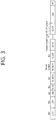
- FIG. 3 is a diagram illustrating an example of an HE PDDU.
- the control information field provided in the embodiment may be the HE-SIG-B included in the HE PPDU.
- the HE PPDU according to FIG. 3 is one example of the PPDU for multiple users and only the PPDU for the multiple users may include the HE-SIG-B and the corresponding HE SIG-B may be omitted in a PPDU for a single user.
- the HE-PPDU for multiple users may include a legacy-short training field (L-STF), a legacy-long training field (L-LTF), a legacy-signal (L-SIG), a high efficiency-signal A (HE-SIG A), a high efficiency-signal-B (HE-SIG B), a high efficiency-short training field (HE-STF), a high efficiency-long training field (HE-LTF), a data field (alternatively, an MAC payload), and a packet extension (PE) field.
- L-STF legacy-short training field
- L-LTF legacy-long training field
- L-SIG legacy-signal
- HE-SIG A high efficiency-signal A
- HE-SIG B high efficiency-short training field
- HE-LTF high efficiency-long training field
- PE packet extension
- the respective fields may be transmitted during an illustrated time period (that is, 4 or 8 ⁇ s).
- FIG. 4 is a diagram illustrating a layout of resource units (RUs) used in a band of 20 MHz.
- resource units corresponding to tone (that is, subcarriers) of different numbers are used to constitute some fields of the HE-PPDU.
- the resources may be allocated by the unit of the RU illustrated with respect to the HE-STF, the HE-LTF, and the data field.
- 26 units that is, units corresponding to 26 tones.
- 6 tones may be used as a guard band in a leftmost band of the 20 MHz band and 5 tones may be used as the guard band in a rightmost band of the 20 MHz band.
- 7 DC tones may be inserted into a center band, that is, a DC band and a 26-unit corresponding to each 13 tones may be present at left and right sides of the DC band.
- the 26-unit, a 52-unit, and a 106-unit may be allocated to other bands. Each unit may be allocated for a receiving station, that is, a user.
- the RU layout of FIG. 4 may be used even in a situation for a single user (SU) in addition to the multiple users (MUs) and in this case, as illustrated in a lowermost part of FIG. 4 , one 242-unit may be used and in this case, three DC tones may be inserted.
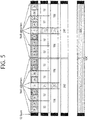
- FIG. 5 is a diagram illustrating a layout of resource units (RUs) used in a band of 40MHz.
- 26-RU, 52-RU, 106-RU, 242-RU, 484-RU, and the like may be used even in one example of FIG. 5 .
- 5 DC tones may be inserted into a center frequency, 12 tones may be used as the guard band in the leftmost band of the 40 MHz band and 11 tones may be used as the guard band in the rightmost band of the 40MHz band.
- FIG. 6 is a diagram illustrating a layout of resource units (RUs) used in a band of 80MHz.
- 26-RU, 52-RU, 106-RU, 242-RU, 484-RU, and the like may be used even in one example of FIG. 6 .
- 7 DC tones may be inserted into the center frequency
- 12 tones may be used as the guard band in the leftmost band of the 80MHz band
- 11 tones may be used as the guard band in the rightmost band of the 80MHz band.
- the 26-RU may be used, which uses 13 tones positioned at each of left and right sides of the DC band.
- 996-RU when the RU layout is used for the single user, 996-RU may be used and in this case, 5 DC tones may be inserted. Meanwhile, the detailed number of RUs may be modified similarly to one example of each of FIG. 4 or 5 .
- the detailed number of RUs may be modified similarly to one example of each of FIG. 4 or 5 .
- FIG. 7 is a diagram illustrating another example of the HE PPDU.
- a block illustrated in FIG. 7 is another example of describing the HE-PPDU block of FIG. 3 in terms of a frequency.
- An illustrated L-STF 700 may include a short training orthogonal frequency division multiplexing (OFDM) symbol.
- the L-STF 700 may be used for frame detection, automatic gain control (AGC), diversity detection, and coarse frequency/time synchronization.
- AGC automatic gain control
- An L-SIG 720 may be used for transmitting control information.
- the L-SIG 720 may include information regarding a data rate and a data length. Further, the L-SIG 720 may be repeatedly transmitted. That is, a new format, in which the L-SIG 720 is repeated (for example, may be referred to as R-LSIG) may be configured.
- An HE-SIG-A 730 may include the control information common to the receiving station.
- the HE-SIG-A 730 may include information on 1) a DL/UL indicator, 2) a BSS color field indicating an identify of a BSS, 3) a field indicating a remaining time of a current TXOP period, 4) a bandwidth field indicating at least one of 20, 40, 80, 160 and 80+80 MHz, 5) a field indicating an MCS technique applied to the HE-SIG-B, 6) an indication field regarding whether the HE-SIG-B is modulated by a dual subcarrier modulation technique for MCS, 7) a field indicating the number of symbols used for the HE-SIG-B, 8) a field indicating whether the HE-SIG-B is configured for a full bandwidth MIMO transmission, 9) a field indicating the number of symbols of the HE-LTF, 10) a field indicating the length of the HE-LTF and a CP length, 11) a field indicating whether an OFDM symbol is present for LDPC coding, 12
- An HE-SIG-B 740 may be included only in the case of the PPDU for the multiple users (MUs) as described above. Principally, an HE-SIG-A 750 or an HE-SIG-B 760 may include resource allocation information (alternatively, virtual resource allocation information) for at least one receiving STA.
- resource allocation information alternatively, virtual resource allocation information
- FIG. 8 is a block diagram illustrating one example of HE-SIG-B according to an embodiment.
- the HE-SIG-B field includes a common field at a frontmost part and the corresponding common field is separated from a field which follows therebehind to be encoded. That is, as illustrated in FIG. 8 , the HE-SIG-B field may include a common field including the common control information and a user-specific field including user-specific control information.
- the common field may include a CRC field corresponding to the common field, and the like and may be coded to be one BCC block.
- the user-specific field subsequent thereafter may be coded to be one BCC block including the "user-specific field" for 2 users and a CRC field corresponding thereto as illustrated in FIG. 8 .
- a previous field of the HE-SIG-B 740 may be transmitted in a duplicated form on an MU PPDU.
- the HE-SIG-B 740 transmitted in some frequency band may even include control information for a data field corresponding to a corresponding frequency band (that is, the fourth frequency band) and a data field of another frequency band (e.g., a second frequency band) other than the corresponding frequency band.
- a format may be provided, in which the HE-SIG-B 740 in a specific frequency band (e.g., the second frequency band) is duplicated with the HE-SIG-B 740 of another frequency band (e.g., the fourth frequency band).
- the HE-SIG B 740 may be transmitted in an encoded form on all transmission resources.
- a field after the HE-SIG B 740 may include individual information for respective receiving STAs receiving the PPDU.
- the L-STF 700, the L-LTF 710, the L-SIG 720, the HE-SIG-A 730, and the HE-SIG-B 740 on the PPDU of FIG. 7 is referred to as a first field
- at least one of the data field 770, the HE-STF 750, and the HE-LTF 760 may be referred to as a second field.
- the first field may include a field associated with a legacy system and the second field may include a field associated with an HE system.
- 256 FFT/IFFT may be applied to a bandwidth of 20 MHz
- 512 FFT/IFFT may be applied to a bandwidth of 40 MHz
- 1024 FFT/IFFT may be applied to a bandwidth of 80 MHz
- 2048 FFT/IFFT may be applied to a bandwidth of continuous 160 MHz or discontinuous 160 MHz.
- the length of the OFDM symbol may be a value acquired by adding the length of a guard interval (GI) to the IDFT/DFT length.
- the length of the GI may have various values such as 0.4 ⁇ s, 0.8 ⁇ s, 1.6 ⁇ s, 2.4 ⁇ s, and 3.2 ⁇ s.
- a frequency band used by the first field and a frequency band used by the second field accurately coincide with each other, but both frequency bands may not completely coincide with each other, in actual.
- a primary band of the first field (L-STF, L-LTF, L-SIG, HE-SIG-A, and HE-SIG-B) corresponding to the first frequency band may be the same as the most portions of a frequency band of the second field (HE-STF, HE-LTF, and Data), but boundary surfaces of the respective frequency bands may not coincide with each other.
- FIGS. 4 to 6 since multiple null subcarriers, DC tones, guard tones, and the like are inserted during arranging the RUs, it may be difficult to accurately adjust the boundary surfaces.
- data which the AP transmits to the STA may be expressed as a terms called downlink data (alternatively, a downlink frame) and data (alternatively, a frame) which the STA transmits to the AP may be expressed as a term called uplink data (alternatively, an uplink frame).
- downlink data alternatively, a downlink frame
- uplink data alternatively, an uplink frame
- transmission from the AP to the STA may be expressed as downlink transmission and transmission from the STA to the AP may be expressed as a term called uplink transmission.
- a PHY protocol data unit (PPDU), a frame, and data transmitted through the downlink transmission may be expressed as terms such as a downlink PPDU, a downlink frame, and downlink data, respectively.
- the PPDU may be a data unit including a PPDU header and a physical layer service data unit (PSDU) (alternatively, a MAC protocol data unit (MPDU)).
- PSDU physical layer service data unit
- MPDU MAC protocol data unit
- the PPDU header may include a PHY header and a PHY preamble and the PSDU (alternatively, MPDU) may include the frame or indicate the frame (alternatively, an information unit of the MAC layer) or be a data unit indicating the frame.
- the PHY header may be expressed as a physical layer convergence protocol (PLCP) header as another term and the PHY preamble may be expressed as a PLCP preamble as another term.
- PLCP physical layer convergence protocol
- a PPDU, a frame, and data transmitted through the uplink transmission may be expressed as terms such as an uplink PPDU, an uplink frame, and uplink data, respectively.
- the whole bandwidth may be used for downlink transmission to one STA and uplink transmission to one STA.
- the AP may perform downlink (DL) multi-user (MU) transmission based on multiple input multiple output (MU MIMO) and the transmission may be expressed as a term called DL MU MIMO transmission.
- DL downlink
- MU multi-user
- MU MIMO multiple input multiple output
- an orthogonal frequency division multiple access (OFDMA) based transmission method is preferably supported for the uplink transmission and/or downlink transmission. That is, data units (e.g., RUs) corresponding to different frequency resources are allocated to the user to perform uplink/downlink communication.
- the AP may perform the DL MU transmission based on the OFDMA and the transmission may be expressed as a term called DL MU OFDMA transmission.
- the AP may transmit the downlink data (alternatively, the downlink frame and the downlink PPDU) to the plurality of respective STAs through the plurality of respective frequency resources on an overlapped time resource.
- the plurality of frequency resources may be a plurality of subbands (alternatively, sub channels) or a plurality of resource units (RUs).
- the DL MU OFDMA transmission may be used together with the DL MU MIMO transmission.
- the DL MU MIMO transmission based on a plurality of space-time streams (alternatively, spatial streams) may be performed on a specific subband (alternatively, sub channel) allocated for the DL MU OFDMA transmission.
- uplink multi-user (UL MU) transmission in which the plurality of STAs transmits data to the AP on the same time resource may be supported.
- Uplink transmission on the overlapped time resource by the plurality of respective STAs may be performed on a frequency domain or a spatial domain.
- different frequency resources may be allocated to the plurality of respective STAs as uplink transmission resources based on the OFDMA.
- the different frequency resources may be different subbands (alternatively, sub channels) or different resources units (RUs).
- the plurality of respective STAs may transmit uplink data to the AP through different frequency resources.
- the transmission method through the different frequency resources may be expressed as a term called a UL MU OFDMA transmission method.
- the UL MU OFDMA transmission and the UL MU MIMO transmission may be used together with each other.
- the UL MU MIMO transmission based on the plurality of space-time streams (alternatively, spatial streams) may be performed on a specific subband (alternatively, sub channel) allocated for the UL MU OFDMA transmission.
- a wireless LAN system which supports the OFDMA technology. That is, the OFDMA technique may be applied to at least one of downlink and uplink. Further, the MU-MIMO technique may be additionally applied to at least one of downlink and uplink.
- the OFDMA technique When the OFDMA technique is used, the multiple channels may be simultaneously used by not one terminal but multiple terminals without the limit by the primary channel rule. Therefore, the wider bandwidth may be operated to improve efficiency of operating a wireless resource.
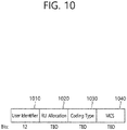
- per user information fields 960#1 to 960#N corresponding to the number of receiving STAs for receiving the trigger frame of FIG. 9 are preferably included.
- the per user information field may be called an "RU allocation field”.
- the control identifier (e.g., 1-bit identifier) may indicate whether a single RU corresponding to a full bandwidth (i.e., 40MHz band) of the transmission frequency band is allocated. That is, whether the 484-RU is allocated for 40MHz transmission may be indicated.
- control identifier e.g., 1-bit identifier
- the control identifier e.g., 1-bit identifier
- the control identifier may also be used to indicate whether to use the aforementioned full bandwidth MU-MIMO.
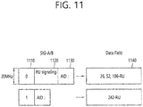
- FIG. 11 is a block diagram illustrating an example of a control field and data field configured according to the present embodiment.
- a left block of FIG. 11 indicates information included in a first and/or second control field of a PPDU
- a right block of FIG. 11 indicates information included in a data field of the PPDU.
- the PPDU related to FIG. 11 may be a PPDU for a multi-user, that is, a plurality of receiving devices. More specifically, a field configuration may vary for the multi-user and the single user, and the example of FIG. 11 may be a PPDU for the multi-user.
- the aforementioned control identifier (e.g., 1-bit identifier) may be omitted.
- a different operation may be performed according to a first control field (e.g., HE-SIG-A) SU/MU identification field. That is, if the SU/MU identification field included in the first control field indicates MU transmission, an example is possible in which the control identifier is omitted and only a 26-type RU is allocated.
- a first control field e.g., HE-SIG-A
- each control field and the data field correspond to a 20MHz band.
- the control identifier is included in a front portion of a common field of the SIG-B.
- the control identifier may be called a "242 unit bitmap".
- the same advantage as in FIG. 11 can be achieved in a sense that RU allocation information can be omitted according to the "242 unit bitmap", and also an overhead decrease effect can be achieved.
- the aforementioned control identifier e.g., 1-bit identifier
- the proposed identifier includes a first identifier indicating whether a 242-type RU is allocated for each 20MHz channel and a second identifier indicating whether a 484-RU (or a different sized 242 type RU) is allocated in a corresponding 20MHz.
- FIG. 13 illustrates an example in which the present specification is applied to 80MHz transmission.
- FIG. 13 relates to the first identifier 1310 and second identifier 1320 as illustrated.
- an example for a frequency mapping relation between the second control field (i.e., SIG-B) and the data field may be additionally applied.
- the SIG-B corresponding to the second channel may allocate the STA3 to a data field corresponding to the second channel, and may allocate the STA4 to a data field corresponding to the fourth channel. That is, the SIG-B corresponding to the second channel may first indicate STA identification information regarding the data field corresponding to the second channel, and thereafter may indicate STA identification information regarding the data field corresponding to the fourth channel.
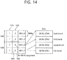
- the first/second identifiers of FIG. 14 may be used in the same manner as the first/second identifiers of FIG. 13 . Further, the example of FIG. 14 may have a predetermined mapping relation between the SIG-B and the data field similarly to the example of FIG. 13 . However, the example of FIG. 14 differs from the example of FIG. 13 in a sense that the SIG-B corresponding to the first channel is mapped to the data field corresponding to the first/second channels, and the SIG-B corresponding to the second channel is mapped to the data field corresponding to the third/fourth channels.
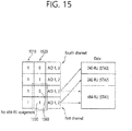
- FIG. 15 illustrates another example according to the present specification.
- a first identifier 1510 is included in a head portion of an SIG-B field corresponding to each 20MHz, followed by a second identifier 1520.
- the first/second identifiers according to the example of FIG. 15 may correspond to the first/second identifiers of FIG. 13 and/or FIG. 14 .
- FIG. 16 illustrates another example according to the present specification.
- a first identifier 1610 is included in a head portion of an SIG-B field corresponding to each 20MHz, followed by a second identifier 1620.
- all or some parts of information of the SIG-B field corresponding to first/second channels may be duplicated to third/fourth channels. That is, as shown in FIG. 16 , the SIG-B field corresponding to the first/second channels indicates ⁇ AID1, 2 ⁇ and ⁇ AID3, 2 ⁇ .
- the SIG-B field corresponding to the third/fourth channels may also indicate ⁇ AID1, 2 ⁇ and ⁇ AID3, 2 ⁇ .
- a second identifier 1650 corresponding to the first channel indicates "0"
- a second identifier 1660 corresponding to the second channel indicates "1”.
- FIG. 16 Extra other features of FIG. 16 are the same as those in the example of FIG. 13 to FIG. 15 .
- FIG. 17 illustrates another example according to the present specification.
- a first identifier 1710 is included in a head portion of an SIG-B field corresponding to each 20MHz, followed by a second identifier 1720.
- all or some parts of information of the SIG-B field corresponding to first/second channels may be duplicated to third/fourth channels. That is, as shown in FIG. 17 , the SIG-B field corresponding to the first/second channels indicates ⁇ AID1 ⁇ and ⁇ AID2 ⁇ . The SIG-B field corresponding to the third/fourth channels may also indicate ⁇ AID1 ⁇ and ⁇ AID2 ⁇ .
- a second identifier 1750 corresponding to the first channel indicates "1"
- a second identifier 1760 corresponding to the second channel indicates "1”. This indicates that a 484-RU is not allocated to the first/second channels, and the 484-RU is allocated to the third/fourth channels.
- FIG. 17 Extra other features of FIG. 17 are the same as those in the example of FIG. 13 to FIG. 16 .
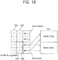
- FIG. 18 illustrates another example according to the present specification.
- a first identifier 1810 is included in a head portion of an SIG-B field corresponding to each 20MHz, followed by a second identifier 1820.
- all or some parts of information of the SIG-B field corresponding to first/second channels may be duplicated to third/fourth channels. That is, as shown in FIG. 18 , the SIG-B field corresponding to the first/second channels indicates ⁇ AID1, 2 ⁇ and ⁇ AID1, 2 ⁇ .
- the SIG-B field corresponding to the third/fourth channels may also indicate ⁇ AID1, 2 ⁇ and ⁇ AID1, 2 ⁇ .
- a second identifier 1850 corresponding to the first channel indicates "1"
- a second identifier 1860 corresponding to the second channel indicates "1”. This indicates that a 484-RU is not allocated to the first/second channels, and the 484-RU is allocated to the third/fourth channels.
- FIG. 18 Extra other features of FIG. 18 are the same as those in the example of FIG. 13 to FIG. 17 .
- a PPDU 1901 of FIG. 19 may include all or some parts of the field shown in FIG. 7 . More specifically, as illustrated, it may include a first control field 1910, second control fields 1920 and 1930, and a data field 1940.
- the first control field 1910 may correspond to the aforementioned SIG-A or HE-SIG-A
- the second control field 1920 may correspond to the aforementioned SIG-B or HE-SIG B.
- the first control field 1910 may include the HE-SIG A 730 of FIG. 7 and a technical feature shown in FIG. 11 to FIG. 18 . More specifically, the first control field 1910 may include control information for interpreting the PPDU 1901.
- the PPDU 1901 may include a sub-field indicating a transmission frequency band at which the PPDU 1901 is transmitted (i.e., indicating 20MHz, 40MHz, 80MHz, 160MHz, etc.).
- the first control field 1910 may include a 1-bit identifier indicating whether a single RU corresponding to a full bandwidth of the transmission frequency band is allocated. If the control identifier (e.g., 1-bit identifier) of the first control field 1910 is set to "1", it indicates that a single RU corresponding to the full bandwidth of the transmission frequency band is allocated. That is, if the transmission frequency band is a 20MHz band, it indicates that a single 242-RU is allocated, and for example, if the transmission frequency band is an 80MHz band, it indicates that a single 996-RU is allocated. Meanwhile, as described above, the 1-bit identifier has a technical advantage in that signaling for full bandwidth MU-MIMO is possible.
- the first control field 1910 may be included in the PPDU 1901 in such a manner of being generated in unit of 20MHz and thereafter being duplicated on the basis of the transmission frequency band. That is, the first control field 1910 may be generated in unit of 20MHz, and may be duplicated according to an 80MHz band.
- the second control field may correspond to the HE-SIG B field including the common field and user specific field shown in FIG. 8 . That is, the second control field may include the common field 1920 and the user specific field 1930.
- common information such as RU allocation information for a user may be included in the common field 1920 of the SIG-B.
- RU allocation information having a form of a look-up table including specific n-bit mapping information may be included.
- the RU allocation information may indicate arrangement or allocation information of an RU applied to the corresponding data field 1940. That is, a structure in which a plurality of RUs are arranged may be indicated as shown in FIG. 4 to FIG. 6 . All STAs which have received the common field 1920 of the second control field may confirm a specific RU by which the corresponding data field 1940 is configured.
- the second control field generally includes allocation information for a resource unit (RU) through the common field 1920.
- a control identifier e.g., 1-bit identifier
- the allocation information for the RU is preferably omitted. That is, the common field 1920 may be omitted. Since only a single RU is used when the control identifier is set to "1", there is no need to configure allocation information for the RU, and thus the common field 1920 can be omitted.
- the common field 1920 of the second control field may include allocation information for the RU, and if the control identifier (e.g., 1-bit identifier) included in the first control field 1910 is set to "1", the common field 1920 of the second control field may not include the allocation information of the RU.
- the control identifier e.g., 1-bit identifier
- the second control fields 1920 and 1930 are used to demodulate the data field 1940.
- the second control field and the data field 1940 may have a mapping relation as shown in FIG. 13 to FIG. 18 .
- the second control field may correspond to first to fourth SIG-B channels. That is, the channel may be classified into four channels in unit of 20MHz.
- the content of second control fields 1921 and 1931 corresponding to the first SIG-B channel may be the same as the content of second control fields 1912 and 1933 corresponding to the third SIG-B channel.
- some parts of the second control field may be duplicated in the PPDU 1901.
- the duplication for the second control field may be implemented in various manners.
- second control fields corresponding to the first to fourth SIG-B channels may be called first, second, third, and fourth signal fields.
- second signal fields 1922 and 1932 may be duplicated to construct fourth signal fields 1924 and 1934. That is, the content of the second control fields 1922 and 1932 corresponding to the second SIG-B channel may be the same as the content of the second control fields 1924 and 1934 corresponding to the fourth SIG-B channel.
- the first signal fields 1921 and 1931 may correspond to a data field 1941 of the first data channel and a data field 1943 of the third data channel.
- the second signal fields 1922 and 1932 may correspond to a data field 1942 of the second data channel and a data field 1944 of the fourth data channel.
- the common field 1921 included in the first signal fields 1920 and 1931 may indicate allocation information for an RU applied to the data field 1941 of the first data channel and allocation information for an RU applied to the data field 1943 of the third data channel.
- the allocation information for the RU applied to the data field 1941 of the first data channel is first inserted in a form of one BCC block in the first signal fields 1921 and 1931, and thereafter one BCC block for the data field 1943 of the third data channel is inserted.
- the user specific field 1931 included in the first signal fields 1921 and 1931 may include identification information (e.g., AID) of an STA allocated to the data field 1941 of the first data channel and identification information (e.g., AID) of an STA allocated to the data field 1943 of the third data channel.
- identification information e.g., AID
- the aforementioned two BCC blocks are inserted into the first signal fields 1921 and 1931 and then an BCC block for an STA allocated to the data field 1941 of the first data channel is inserted. Thereafter, a BCC block for an STA allocated to the data field 1943 of the third data channel is inserted.
- each SIG-B channel and data channel correspond to the four frequency bands described in FIG. 7 . That is, as described in the example of FIG. 7 , each boundary surface of the data channel and each boundary surface of the SIG-B channel may not be completely aligned.
- the second control fields 1921 and 1931 corresponding to a first frequency band correspond to the two data fields 1941 and 1943 corresponding to the first/third frequency bands.
- the second control fields 1922 and 1932 corresponding to the second frequency band correspond to the two data fields 1942 and 1944 corresponding to the second/fourth frequency bands.
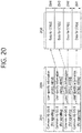
- FIG. 20 illustrates an example of SIG-B used for 80MHz transmission.
- the SIG-B includes a common field 2010 and a user specific field 2020.
- the common field 2010 and user specific field 2020 of the SIG-B include four fields respectively corresponding to four frequency bands 2041, 2042, 2043, and 2044 each of which corresponds to a 20MHz channel.
- the four distinctive SIG-B fields in FIG. 20 may be called in various terms such as first to fourth signal fields or the like.
- the SIG-B corresponding to the first frequency band 2041 is mapped to data fields of first and third frequency bands
- the SIG-B corresponding to the second frequency band 2042 is mapped to data fields of the second and fourth frequency bands.
- the SIG-B corresponding to the first frequency band 2041 may be duplicated to construct the SIG-B corresponding to the third frequency band 2043
- the SIG-B corresponding to the second frequency band 2042 may be duplicated to construct the SIG-B corresponding to the fourth frequency band 2044.
- the common field corresponding to the first frequency band 2041 includes an RU signalling field, and this is used for the data field corresponding to the first and third frequency bands.
- Each RU signalling field shown in FIG. 20 may be constructed of one look-up table with respect to 20MHz. Since the common field corresponding to the first frequency band 2041 corresponds to the data field corresponding to two frequency bands, two RU signalling fields are simultaneously transmitted. A first field of the two RU signalling fields indicates the data field corresponding to the first frequency band 2041, and a second field indicates the data field corresponding to the third frequency band 2043.
- the SIG-B corresponding to the second frequency band 2042 includes two RU signalling fields for the data field corresponding to the second and fourth frequency bands 2042 and 2044.
- the two RU signalling fields may correspond to one unified look-up table instead of being present independently with each other. That is, it may be designed to instruct non-contiguous 40MHz allocation.
- the SIG-B corresponding to the first and second frequency bands is duplicated on the third and fourth frequency bands.
- the aforementioned example may be modified in various manners.
- an additional technique feature described below may be applied to the RU look-up table and the RU signalling field.
- RUs corresponding to a 20MHz band may be constructed by combining 26-RU, 52-RU, 106-RU (or 242-RU, aggregate 484-RU, 996-RU).
- the RU look-up table may be constructed through 5-bit information.
- it is configured to use a MU-MIMO scheme only for at least 106-RU, about 12 cases are present regarding 106-RU allocation.
- a 3-bit or 4-bit MU-MIMO indicator i.e., MU-MIMO field
- signalling may be performed with respect to 20MHz for: 1) information regarding a combination of RUs; and 2) information regarding an RU to which MU-MIMO is applied.
- signalling related to the MU-MIMO scheme may be actualized as follows.
- a 3-bit or 4-bit MU-MIMO indicator (i.e., MU-MIMO field) may be actualized as follows.
- 3-bit MU-MIMO indicator The total number of user STAs that can be multiplexed to the 106-RU is 8. For example, the total number of users can be indicated. More specifically, "000" and “111" may respectively indicate that 1 and 8 user STAs are multiplexed to the 106-RU according to the MU-MIMO scheme. That is, the number of user STAs to be multiplexed according to the MU-MIMO scheme may be indicated while indicating that the MU-MIMO scheme is applied.
- the MU-MIMO indicator (i.e., MU-MIMO field) may be actualized as follows.
- a user STA to be multiplexed to each 106-RU may be indicated in unit of 2 bits.
- a combination of the number of users that can be multiplexed to each 106-RU may be limited, and may be configured as follows for example.
- the combination of user STAs that can be allocated to each 106-RU may be indicated by using 16 cases expressed with 3-bit information.
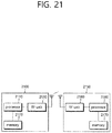
- FIG. 21 is a block diagram illustrating a wireless device to which the present embodiment is applicable.
- a wireless device is an STA capable of implementing the aforementioned embodiment, and may be an AP 2100 or a non-AP STA.
- the wireless device may correspond to the aforementioned user, or may correspond to a transmission device for transmitting a signal to the user.
- the AP 2100 includes a processor 2110, a memory 2120, and a radio frequency (RF) unit 2130.
- the RF unit 2130 may be coupled to the processor 2110 to transmit/receive a radio signal.
- the processor 2110 may implement the functions, procedures, and/or methods proposed in the present specification.
- the processor 2110 may be configured to perform an operation according to the aforementioned embodiment. That is, the processor 2110 may perform an operation that can be performed by the AP among operations disclosed in the embodiment of FIG. 1 to FIG. 20 .
- a non-AP STA 2150 includes a processor 2160, a memory 2170, and an RF unit 2180.
- the RF unit 2180 may be coupled to the processor 2160 to transmit/receive a radio signal.
- the processor 2160 may implement the functions, procedures, and/or methods proposed in the present invention.
- the processor 2160 may be configured to perform an operation of the non-AP STA according to the aforementioned embodiment.
- the processor may perform the operation of the non-AP STA disclosed in the embodiment of FIG. 1 to FIG. 20 .
- the processors 2110 and 2160 may include application-specific integrated circuits (ASICs), other chipsets, logical circuits, data processing devices, and/or converters for mutually converting a baseband signal and a radio signal.
- the memories 2120 and 2170 may include a read-only memory (ROM), a random access memory (RAM), a flash memory, a memory card, a storage medium and/or other storage devices.
- the RF units 2130 and 2180 may include at least one antenna to transmit and/or receive the radio signal.
- the above-described scheme may be implemented using a module (procedure, function, etc.) which performs the above function.
- the module may be stored in the memories 2120 and 2170, and may be executed by the processors 2110 and 2160.
- the memories 2120 and 2170 may be disposed to the processors 2110 and 2160 internally or externally, and may be connected to the processors 2110 and 2160 using a variety of well-known means.
Landscapes
- Engineering & Computer Science (AREA)
- Signal Processing (AREA)
- Computer Networks & Wireless Communication (AREA)
- Quality & Reliability (AREA)
- Mobile Radio Communication Systems (AREA)
Description
- The present specification relates to a technique for transmitting/receiving data in wireless communication, and more particularly, to a method and apparatus for constructing a control field including information regarding a resource unit in a wireless local area network (WLAN) system.
- Discussion for a next-generation wireless local area network (WLAN) is in progress. In the next-generation WLAN, an object is to 1) improve an institute of electronic and electronics engineers (IEEE) 802.11 physical (PHY) layer and a medium access control (MAC) layer in bands of 2.4 GHz and 5 GHz, 2) increase spectrum efficiency and area throughput, 3) improve performance in actual indoor and outdoor environments such as an environment in which an interference source exists, a dense heterogeneous network environment, and an environment in which a high user load exists, and the like.
- An environment which is primarily considered in the next-generation WLAN is a dense environment in which access points (APs) and stations (STAs) are a lot and under the dense environment, improvement of the spectrum efficiency and the area throughput is discussed. Further, in the next-generation WLAN, in addition to the indoor environment, in the outdoor environment which is not considerably considered in the existing WLAN, substantial performance improvement is concerned.
- In detail, scenarios such as wireless office, smart home, stadium, Hotspot, and building/apartment are largely concerned in the next-generation WLAN and discussion about improvement of system performance in a dense environment in which the APs and the STAs are a lot is performed based on the corresponding scenarios.
- In the next-generation WLAN, improvement of system performance in an overlapping basic service set (OBSS) environment and improvement of outdoor environment performance, and cellular offloading are anticipated to be actively discussed rather than improvement of single link performance in one basic service set (BSS). Directionality of the next-generation means that the next-generation WLAN gradually has a technical scope similar to mobile communication. When a situation is considered, in which the mobile communication and the WLAN technology have been discussed in a small cell and a direct-to-direct (D2D) communication area in recent years, technical and business convergence of the next-generation WLAN and the mobile communication is predicted to be further active.
- Document "HE-SIG-B Structure", IEEE 802.11-15/0821R2, XP055514113, outlines an HE signal field structure for which HE-SIG-B does not have any OFDM symbol that is fully duplicated over operating BW and information regarding resource allocation and STA-ID in HE SIG-B.
-
WO 2015/064943 A1 discloses a method and device for transmitting data in a wireless local area network. An access point receives a plurality of transmission opportunity (TXOP) requests for requesting a TXOP configuration from a plurality of transmission stations. The access point transmits a TXOP polling regarding the TXOP configuration to the plurality of transmission stations. The access point receives a plurality of data blocks from the plurality of transmission stations during the configured TXOP. - The present specification proposes a control field including information regarding a resource unit in a wireless local area network (WLAN) system.
- The present specification proposes a control field constructed on the basis of multiple channels or frequency bands.
- The present invention is defined in the appended claims. A method according to the present specification may be applied to a WLAN system using at least one resource unit (RU) corresponding to a predetermined frequency band.
- An embodiment of the present specification proposes an improved control field including information regarding a resource unit.
- The control field according to the present specification may be constructed on the basis of multiple channels or frequency bands.
-
-
FIG. 1 is a conceptual view illustrating the structure of a wireless local area network (WLAN). -
FIG. 2 is a diagram illustrating an example of a physical layer (PHY) protocol data unit (PPDU) used in an institute of electronic and electronics engineers (IEEE) standard. -
FIG. 3 is a diagram illustrating an example of a high efficiency (HE) PDDU. -
FIG. 4 is a diagram illustrating a layout of resource units (RUs) used in a band of 20 MHz. -
FIG. 5 is a diagram illustrating a layout of RUs used in a band of 40MHz. -
FIG. 6 is a diagram illustrating a layout of RUs used in a band of 80MHz. -
FIG. 7 is a diagram illustrating another example of the HE PPDU. -
FIG. 8 is a block diagram illustrating one example of high efficiency signal B (HE-SIG-B) according to an embodiment. -
FIG. 9 illustrates an example of a trigger frame. -
FIG. 10 illustrates an example of a sub-field included in a per user information field. -
FIG. 11 is a block diagram illustrating an example of a control field and data field configured according to the present embodiment. -
FIG. 12 illustrates an example of the present embodiment for 40MHz transmission. -
FIG. 13 illustrates an example in which the present specification is applied to 80MHz transmission. -
FIG. 14 illustrates an example of modifying a control signal according to the present specification. -
FIG. 15 illustrates an additional example of modifying a control signal according to the present specification. -
FIG. 16 illustrates an example of modifying a control signal and frequency mapping relation according to the present specification. -
FIG. 17 illustrates an example of modifying a control signal and frequency mapping relation according to the present specification. -
FIG. 18 illustrates an additional example of a control signal and frequency mapping relation according to the present specification. -
FIG. 19 illustrates a relation of SIG-A, SIG-B, and data fields according to the present embodiment. -
FIG. 20 illustrates an example of SIG-B used for 80MHz transmission. -
FIG. 21 is a block diagram illustrating a wireless device to which the present embodiment is applicable. -
FIG. 1 is a conceptual view illustrating the structure of a wireless local area network (WLAN). - An upper part of
FIG. 1 illustrates the structure of an infrastructure basic service set (BSS) of institute of electrical and electronic engineers (IEEE) 802.11. - Referring the upper part of
FIG. 1 , the wireless LAN system may include one ormore infrastructure BSSs 100 and 105 (hereinafter, referred to as BSS). TheBSSs - The BSS may include at least one STA, APs providing a distribution service, and a distribution system (DS) 110 connecting multiple APs.
- The
distribution system 110 may implement an extended service set (ESS) 140 extended by connecting themultiple BSSs more APs 125 or 230 through thedistribution system 110. The AP included in oneESS 140 may have the same service set identification (SSID). - A
portal 120 may serve as a bridge which connects the wireless LAN network (IEEE 802.11) and another network (e.g., 802.X). - In the BSS illustrated in the upper part of
FIG. 1 , a network between theAPs APs APs APs - A lower part of
FIG. 1 illustrates a conceptual view illustrating the IBSS. - Referring to the lower part of
FIG. 1 , the IBSS is a BSS that operates in an Ad-Hoc mode. Since the IBSS does not include the access point (AP), a centralized management entity that performs a management function at the center does not exist. That is, in the IBSS, STAs 150-1, 150-2, 150-3, 155-4, and 155-5 are managed by a distributed manner. In the IBSS, all STAs 150-1, 150-2, 150-3, 155-4, and 155-5 may be constituted by movable STAs and are not permitted to access the DS to constitute a self-contained network. - The STA as a predetermined functional medium that includes a medium access control (MAC) that follows a regulation of an Institute of Electrical and Electronics Engineers (IEEE) 802.11 standard and a physical layer interface for a radio medium may be used as a meaning including all of the APs and the non-AP stations (STAs).
- The STA may be called various a name such as a mobile terminal, a wireless device, a wireless transmit/receive unit (WTRU), user equipment (UE), a mobile station (MS), a mobile subscriber unit, or just a user.
-
FIG. 2 is a diagram illustrating an example of a PPDU used in an IEEE standard. - As illustrated in
FIG. 2 , various types of PHY protocol data units (PPDUs) may be used in a standard such as IEEE a/g/n/ac, etc. In detail, LTF and STF fields include a training signal, SIG-A and SIG-B include control information for a receiving station, and a data field includes user data corresponding to a PSDU. - In the embodiment, an improved technique is provided, which is associated with a signal (alternatively, a control information field) used for the data field of the PPDU. The signal provided in the embodiment may be applied onto high efficiency PPDU (HE PPDU) according to an IEEE 802.11ax standard. That is, the signal improved in the embodiment may be HE-SIG-A and/or HE-SIG-B included in the HE PPDU. The HE-SIG-A and the HE-SIG-B may be represented even as the SIG-A and SIG-B, respectively. However, the improved signal proposed in the embodiment is not particularly limited to an HE-SIG-A and/or HE-SIG-B standard and may be applied to control/data fields having various names, which include the control information in a wireless communication system transferring the user data.
-
FIG. 3 is a diagram illustrating an example of an HE PDDU. - The control information field provided in the embodiment may be the HE-SIG-B included in the HE PPDU. The HE PPDU according to
FIG. 3 is one example of the PPDU for multiple users and only the PPDU for the multiple users may include the HE-SIG-B and the corresponding HE SIG-B may be omitted in a PPDU for a single user. - As illustrated in
FIG. 3 , the HE-PPDU for multiple users (MUs) may include a legacy-short training field (L-STF), a legacy-long training field (L-LTF), a legacy-signal (L-SIG), a high efficiency-signal A (HE-SIG A), a high efficiency-signal-B (HE-SIG B), a high efficiency-short training field (HE-STF), a high efficiency-long training field (HE-LTF), a data field (alternatively, an MAC payload), and a packet extension (PE) field. The respective fields may be transmitted during an illustrated time period (that is, 4 or 8 µs). - More detailed description of the respective fields of
FIG. 3 will be made below. -
FIG. 4 is a diagram illustrating a layout of resource units (RUs) used in a band of 20 MHz. - As illustrated in
FIG. 4 , resource units (RUs) corresponding to tone (that is, subcarriers) of different numbers are used to constitute some fields of the HE-PPDU. For example, the resources may be allocated by the unit of the RU illustrated with respect to the HE-STF, the HE-LTF, and the data field. - As illustrated in an uppermost part of
FIG. 4 , 26 units (that is, units corresponding to 26 tones). 6 tones may be used as a guard band in a leftmost band of the 20 MHz band and 5 tones may be used as the guard band in a rightmost band of the 20 MHz band. Further, 7 DC tones may be inserted into a center band, that is, a DC band and a 26-unit corresponding to each 13 tones may be present at left and right sides of the DC band. The 26-unit, a 52-unit, and a 106-unit may be allocated to other bands. Each unit may be allocated for a receiving station, that is, a user. - Meanwhile, the RU layout of
FIG. 4 may be used even in a situation for a single user (SU) in addition to the multiple users (MUs) and in this case, as illustrated in a lowermost part ofFIG. 4 , one 242-unit may be used and in this case, three DC tones may be inserted. - In one example of
FIG. 4 , RUs having various sizes, that is, a 26-RU, a 52-RU, a 106-RU, a 242-RU, and the like are proposed, and as a result, since detailed sizes of the RUs may extend or increase, the embodiment is not limited to a detailed size (that is, the number of corresponding tones) of each RU. -
FIG. 5 is a diagram illustrating a layout of resource units (RUs) used in a band of 40MHz. - Similarly to a case in which the RUs having various RUs are used in one example of
FIG. 4 , 26-RU, 52-RU, 106-RU, 242-RU, 484-RU, and the like may be used even in one example ofFIG. 5 . Further, 5 DC tones may be inserted into a center frequency, 12 tones may be used as the guard band in the leftmost band of the 40 MHz band and 11 tones may be used as the guard band in the rightmost band of the 40MHz band. - In addition, as illustrated in
FIG. 5 , when the RU layout is used for the single user, the 484-RU may be used. That is, the detailed number of RUs may be modified similarly to one example ofFIG. 4 . -
FIG. 6 is a diagram illustrating a layout of resource units (RUs) used in a band of 80MHz. - Similarly to a case in which the RUs having various RUs are used in one example of each of
FIG. 4 or5 , 26-RU, 52-RU, 106-RU, 242-RU, 484-RU, and the like may be used even in one example ofFIG. 6 . Further, 7 DC tones may be inserted into the center frequency, 12 tones may be used as the guard band in the leftmost band of the 80MHz band and 11 tones may be used as the guard band in the rightmost band of the 80MHz band. In addition, the 26-RU may be used, which uses 13 tones positioned at each of left and right sides of the DC band. - Moreover, as illustrated in
FIG. 6 , when the RU layout is used for the single user, 996-RU may be used and in this case, 5 DC tones may be inserted. Meanwhile, the detailed number of RUs may be modified similarly to one example of each ofFIG. 4 or5 . - Meanwhile, the detailed number of RUs may be modified similarly to one example of each of
FIG. 4 or5 . -
FIG. 7 is a diagram illustrating another example of the HE PPDU. - A block illustrated in
FIG. 7 is another example of describing the HE-PPDU block ofFIG. 3 in terms of a frequency. - An illustrated L-
STF 700 may include a short training orthogonal frequency division multiplexing (OFDM) symbol. The L-STF 700 may be used for frame detection, automatic gain control (AGC), diversity detection, and coarse frequency/time synchronization. - An L-
LTF 710 may include a long training orthogonal frequency division multiplexing (OFDM) symbol. The L-LTF 710 may be used for fine frequency/time synchronization and channel prediction. - An L-
SIG 720 may be used for transmitting control information. The L-SIG 720 may include information regarding a data rate and a data length. Further, the L-SIG 720 may be repeatedly transmitted. That is, a new format, in which the L-SIG 720 is repeated (for example, may be referred to as R-LSIG) may be configured. - An HE-SIG-
A 730 may include the control information common to the receiving station. - In detail, the HE-SIG-
A 730 may include information on 1) a DL/UL indicator, 2) a BSS color field indicating an identify of a BSS, 3) a field indicating a remaining time of a current TXOP period, 4) a bandwidth field indicating at least one of 20, 40, 80, 160 and 80+80 MHz, 5) a field indicating an MCS technique applied to the HE-SIG-B, 6) an indication field regarding whether the HE-SIG-B is modulated by a dual subcarrier modulation technique for MCS, 7) a field indicating the number of symbols used for the HE-SIG-B, 8) a field indicating whether the HE-SIG-B is configured for a full bandwidth MIMO transmission, 9) a field indicating the number of symbols of the HE-LTF, 10) a field indicating the length of the HE-LTF and a CP length, 11) a field indicating whether an OFDM symbol is present for LDPC coding, 12) a field indicating control information regarding packet extension (PE), 13) a field indicating information on a CRC field of the HE-SIG-A, and the like. A detailed field of the HE-SIG-A may be added or partially omitted. Further, some fields of the HE-SIG-A may be partially added or omitted in other environments other than a multi-user (MU) environment. - An HE-SIG-
B 740 may be included only in the case of the PPDU for the multiple users (MUs) as described above. Principally, an HE-SIG-A 750 or an HE-SIG-B 760 may include resource allocation information (alternatively, virtual resource allocation information) for at least one receiving STA. -
FIG. 8 is a block diagram illustrating one example of HE-SIG-B according to an embodiment. - As illustrated in
FIG. 8 , the HE-SIG-B field includes a common field at a frontmost part and the corresponding common field is separated from a field which follows therebehind to be encoded. That is, as illustrated inFIG. 8 , the HE-SIG-B field may include a common field including the common control information and a user-specific field including user-specific control information. In this case, the common field may include a CRC field corresponding to the common field, and the like and may be coded to be one BCC block. The user-specific field subsequent thereafter may be coded to be one BCC block including the "user-specific field" for 2 users and a CRC field corresponding thereto as illustrated inFIG. 8 . - A previous field of the HE-SIG-
B 740 may be transmitted in a duplicated form on an MU PPDU. In the case of the HE-SIG-B 740, the HE-SIG-B 740 transmitted in some frequency band (e.g., a fourth frequency band) may even include control information for a data field corresponding to a corresponding frequency band (that is, the fourth frequency band) and a data field of another frequency band (e.g., a second frequency band) other than the corresponding frequency band. Further, a format may be provided, in which the HE-SIG-B 740 in a specific frequency band (e.g., the second frequency band) is duplicated with the HE-SIG-B 740 of another frequency band (e.g., the fourth frequency band). Alternatively, the HE-SIG B 740 may be transmitted in an encoded form on all transmission resources. A field after the HE-SIG B 740 may include individual information for respective receiving STAs receiving the PPDU. - The HE-
STF 750 may be used for improving automatic gain control estimation in a multiple input multiple output (MIMO) environment or an OFDMA environment. - The HE-
LTF 760 may be used for estimating a channel in the MIMO environment or the OFDMA environment. - The size of fast Fourier transform (FFT)/inverse fast Fourier transform (IFFT) applied to the HE-
STF 750 and the field after the HE-STF 750, and the size of the FFT/IFFT applied to the field before the HE-STF 750 may be different from each other. For example, the size of the FFT/IFFT applied to the HE-STF 750 and the field after the HE-STF 750 may be four times larger than the size of the FFT/IFFT applied to the field before the HE-STF 750. - For example, when at least one field of the L-
STF 700, the L-LTF 710, the L-SIG 720, the HE-SIG-A 730, and the HE-SIG-B 740 on the PPDU ofFIG. 7 is referred to as a first field, at least one of thedata field 770, the HE-STF 750, and the HE-LTF 760 may be referred to as a second field. The first field may include a field associated with a legacy system and the second field may include a field associated with an HE system. In this case, the fast Fourier transform (FFT) size and the inverse fast Fourier transform (IFFT) size may be defined as a size which is N (N is a natural number, e.g., N = 1, 2, and 4) times larger than the FFT/IFFT size used in the legacy wireless LAN system. That is, the FFT/IFFT having the size may be applied, which is N (=4) times larger than the first field of the HE PPDU. For example, 256 FFT/IFFT may be applied to a bandwidth of 20 MHz, 512 FFT/IFFT may be applied to a bandwidth of 40 MHz, 1024 FFT/IFFT may be applied to a bandwidth of 80 MHz, and 2048 FFT/IFFT may be applied to a bandwidth of continuous 160 MHz or discontinuous 160 MHz. - In other words, a subcarrier space/subcarrier spacing may have a size which is 1/N times (N is the natural number, e.g., N = 4, the subcarrier spacing is set to 78.125 kHz) the subcarrier space used in the legacy wireless LAN system. That is, subcarrier spacing having a size of 312.5 kHz, which is legacy subcarrier spacing may be applied to the first field of the HE PPDU and a subcarrier space having a size of 78.125 kHz may be applied to the second field of the HE PPDU.
- Alternatively, an IDFT/DFT period applied to each symbol of the first field·may be expressed to be N (=4) times shorter than the IDFT/DFT period applied to each data symbol of the second field. That is, the IDFT/DFT length applied to each symbol of the first field of the HE PPDU may be expressed as 3.2 µs and the IDFT/DFT length applied to each symbol of the second field of the HE PPDU may be expressed as 3.2 µs * 4 (= 12.8µs). The length of the OFDM symbol may be a value acquired by adding the length of a guard interval (GI) to the IDFT/DFT length. The length of the GI may have various values such as 0.4 µs, 0.8 µs, 1.6 µs, 2.4 µs, and 3.2 µs.
- For simplicity in the description, in
FIG. 7 , it is expressed that a frequency band used by the first field and a frequency band used by the second field accurately coincide with each other, but both frequency bands may not completely coincide with each other, in actual. For example, a primary band of the first field (L-STF, L-LTF, L-SIG, HE-SIG-A, and HE-SIG-B) corresponding to the first frequency band may be the same as the most portions of a frequency band of the second field (HE-STF, HE-LTF, and Data), but boundary surfaces of the respective frequency bands may not coincide with each other. As illustrated inFIGS. 4 to 6 , since multiple null subcarriers, DC tones, guard tones, and the like are inserted during arranging the RUs, it may be difficult to accurately adjust the boundary surfaces. - The user (e.g., a receiving station) may receive the HE-SIG-
A 730 and may be instructed to receive the downlink PPDU based on the HE-SIG-A 730. In this case, the STA may perform decoding based on the FFT size changed from the HE-STF 750 and the field after the HE-STF 750. On the contrary, when the STA may not be instructed to receive the downlink PPDU based on the HE-SIG-A 730, the STA may stop the decoding and configure a network allocation vector (NAV). A cyclic prefix (CP) of the HE-STF 750 may have a larger size than the CP of another field and the during the CP period, the STA may perform the decoding for the downlink PPDU by changing the FFT size. - Hereinafter, in the embodiment of the present invention, data (alternatively, or a frame) which the AP transmits to the STA may be expressed as a terms called downlink data (alternatively, a downlink frame) and data (alternatively, a frame) which the STA transmits to the AP may be expressed as a term called uplink data (alternatively, an uplink frame). Further, transmission from the AP to the STA may be expressed as downlink transmission and transmission from the STA to the AP may be expressed as a term called uplink transmission.
- In addition, a PHY protocol data unit (PPDU), a frame, and data transmitted through the downlink transmission may be expressed as terms such as a downlink PPDU, a downlink frame, and downlink data, respectively. The PPDU may be a data unit including a PPDU header and a physical layer service data unit (PSDU) (alternatively, a MAC protocol data unit (MPDU)). The PPDU header may include a PHY header and a PHY preamble and the PSDU (alternatively, MPDU) may include the frame or indicate the frame (alternatively, an information unit of the MAC layer) or be a data unit indicating the frame. The PHY header may be expressed as a physical layer convergence protocol (PLCP) header as another term and the PHY preamble may be expressed as a PLCP preamble as another term.
- Further, a PPDU, a frame, and data transmitted through the uplink transmission may be expressed as terms such as an uplink PPDU, an uplink frame, and uplink data, respectively.
- In the wireless LAN system to which the embodiment of the present description is applied, the whole bandwidth may be used for downlink transmission to one STA and uplink transmission to one STA. Further, in the wireless LAN system to which the embodiment of the present description is applied, the AP may perform downlink (DL) multi-user (MU) transmission based on multiple input multiple output (MU MIMO) and the transmission may be expressed as a term called DL MU MIMO transmission.
- In addition, in the wireless LAN system according to the embodiment, an orthogonal frequency division multiple access (OFDMA) based transmission method is preferably supported for the uplink transmission and/or downlink transmission. That is, data units (e.g., RUs) corresponding to different frequency resources are allocated to the user to perform uplink/downlink communication. In detail, in the wireless LAN system according to the embodiment, the AP may perform the DL MU transmission based on the OFDMA and the transmission may be expressed as a term called DL MU OFDMA transmission. When the DL MU OFDMA transmission is performed, the AP may transmit the downlink data (alternatively, the downlink frame and the downlink PPDU) to the plurality of respective STAs through the plurality of respective frequency resources on an overlapped time resource. The plurality of frequency resources may be a plurality of subbands (alternatively, sub channels) or a plurality of resource units (RUs). The DL MU OFDMA transmission may be used together with the DL MU MIMO transmission. For example, the DL MU MIMO transmission based on a plurality of space-time streams (alternatively, spatial streams) may be performed on a specific subband (alternatively, sub channel) allocated for the DL MU OFDMA transmission.
- Further, in the wireless LAN system according to the embodiment, uplink multi-user (UL MU) transmission in which the plurality of STAs transmits data to the AP on the same time resource may be supported. Uplink transmission on the overlapped time resource by the plurality of respective STAs may be performed on a frequency domain or a spatial domain.
- When the uplink transmission by the plurality of respective STAs is performed on the frequency domain, different frequency resources may be allocated to the plurality of respective STAs as uplink transmission resources based on the OFDMA. The different frequency resources may be different subbands (alternatively, sub channels) or different resources units (RUs). The plurality of respective STAs may transmit uplink data to the AP through different frequency resources. The transmission method through the different frequency resources may be expressed as a term called a UL MU OFDMA transmission method.
- When the uplink transmission by the plurality of respective STAs is performed on the spatial domain, different time-space streams (alternatively, spatial streams) may be allocated to the plurality of respective STAs and the plurality of respective STAs may transmit the uplink data to the AP through the different time-space streams. The transmission method through the different spatial streams may be expressed as a term called a UL MU MIMO transmission method.
- The UL MU OFDMA transmission and the UL MU MIMO transmission may be used together with each other. For example, the UL MU MIMO transmission based on the plurality of space-time streams (alternatively, spatial streams) may be performed on a specific subband (alternatively, sub channel) allocated for the UL MU OFDMA transmission.
- In the legacy wireless LAN system which does not support the MU OFDMA transmission, a multi-channel allocation method is used for allocating a wider bandwidth (e.g., a 20 MHz excess bandwidth) to one terminal. When a channel unit is 20 MHz, multiple channels may include a plurality of 20 MHz-channels. In the multi-channel allocation method, a primary channel rule is used to allocate the wider bandwidth to the terminal. When the primary channel rule is used, there is a limit for allocating the wider bandwidth to the terminal. In detail, according to the primary channel rule, when a secondary channel adjacent to a primary channel is used in an overlapped BSS (OBSS) and is thus busy, the STA may use remaining channels other than the primary channel. Therefore, since the STA may transmit the frame only to the primary channel, the STA receives a limit for transmission of the frame through the multiple channels. That is, in the legacy wireless LAN system, the primary channel rule used for allocating the multiple channels may be a large limit in obtaining a high throughput by operating the wider bandwidth in a current wireless LAN environment in which the OBSS is not small.
- In order to solve the problem, in the embodiment, a wireless LAN system is disclosed, which supports the OFDMA technology. That is, the OFDMA technique may be applied to at least one of downlink and uplink. Further, the MU-MIMO technique may be additionally applied to at least one of downlink and uplink. When the OFDMA technique is used, the multiple channels may be simultaneously used by not one terminal but multiple terminals without the limit by the primary channel rule. Therefore, the wider bandwidth may be operated to improve efficiency of operating a wireless resource.
- As described above, in case the uplink transmission performed by each of the multiple STAs (e.g., non-AP STAs) is performed within the frequency domain, the AP may allocate different frequency resources respective to each of the multiple STAs as uplink transmission resources based on OFDMA. Additionally, as described above, the frequency resources each being different from one another may correspond to different subbands (or sub-channels) or different resource units (RUs).
- The different frequency resources respective to each of the multiple STAs are indicated through a trigger frame.
-
FIG. 9 illustrates an example of a trigger frame. The trigger frame ofFIG. 9 allocates resources for Uplink Multiple-User (MU) transmission and may be transmitted from the AP. The trigger frame may be configured as a MAC frame and may be included in the PPDU. For example, the trigger frame may be transmitted through the PPDU shown inFIG. 3 , through the legacy PPDU shown inFIG. 2 , or through a certain PPDU, which is newly designed for the corresponding trigger frame. In case the trigger frame is transmitted through the PPDU ofFIG. 3 , the trigger frame may be included in the data field shown in the drawing. - Each of the fields shown in
FIG. 9 may be partially omitted, or other fields may be added. Moreover, the length of each field may be varied differently as shown in the drawing. - A
Frame Control field 910 shown inFIG. 9 may include information related to a version of the MAC protocol and other additional control information, and aDuration field 920 may include time information for configuring a NAV or information related to an identifier (e.g., AID) of the user equipment. - In addition, the
RA field 930 may include address information of the receiving STA of a corresponding trigger frame, and may be optionally omitted. TheTA field 940 includes address information of an STA (e.g., AP) for transmitting the trigger frame, and thecommon information field 950 includes common control information applied to the receiving STA for receiving the trigger frame. For example, information for controlling the content of a field indicating a length of an L-SIG field of an uplink PPDU transmitted in response to the trigger frame or an SIG-A (i.e., HE SIG-A field) of the uplink PPDU transmitted in response to the trigger frame may be included. Further, information regarding a length of a CP of the uplink PPDU transmitted in response to the trigger frame or information regarding a length of an LTF field may be included as common control information. - In addition, per user information fields 960#1 to 960#N corresponding to the number of receiving STAs for receiving the trigger frame of
FIG. 9 are preferably included. The per user information field may be called an "RU allocation field". - In addition, the trigger frame of
FIG. 9 may include apadding field 970 and a framecheck sequence field 980. - Each of the per user information fields 960#1 to 960#N shown in
FIG. 9 preferably includes a plurality of sub-fields. -
FIG. 10 illustrates an example of a sub-field included in a per user information field. Some parts of the sub-field ofFIG. 10 may be omitted, and extra sub-fields may be added. Further, a length of each of the sub-fields shown herein may change. - A
user identifier field 1010 ofFIG. 10 indicates an identifier of an STA (i.e., a receiving STA) corresponding to per user information. An example of the identifier may be all or some parts of an AID. - In addition, an
RU allocation field 1020 may be included. That is, if a receiving STA identified by theuser identifier field 1010 transmits an uplink PPDU in response to the trigger frame ofFIG. 9 , the uplink PPDU is transmitted through an RU indicated by theRU allocation field 1020. In this case, the RU indicated by theRU allocation field 1020 preferably indicates the RU shown inFIG. 4 ,FIG. 5 , andFIG. 6 . A configuration of theRU allocation field 1020 is described below in detail. - The sub-field of
FIG. 10 may include acoding type field 1030. Thecoding type field 1030 may indicate a coding type of an uplink PPDU transmitted in response to the trigger frame ofFIG. 9 . For example, if BCC coding is applied to the uplink PPDU, thecoding type field 1030 may be set to '1', and if LDPC coding is applied, thecoding type field 1030 may be set to '0'. - In addition, the sub-field of
FIG. 10 may include anMCS field 1040. TheMCS field 1040 may indicate an MCS scheme applied to the uplink PPDU transmitted in response to the trigger frame ofFIG. 9 . For example, if BCC coding is applied to the uplink PPDU, thecoding type field 1030 may be set to '1', and if LDPC coding is applied, thecoding type field 1030 may be set to '0'. - Hereinafter, the present specification proposes an example of improving a control field included in a PPDU. The control field improved by the present specification includes a first control field including control information required to interpret the PPDU and a second control field including control information for demodulating a data field of the PPDU. The first and second control fields may be various fields. For example, the first control field may be the HE-SIG-
A 730 shown inFIG. 7 , and the second control field may be the HE-SIG-B 740 shown inFIG. 7 andFIG. 8 . - Hereinafter, an example of improving the first and second control fields is described in detail.
- The following example proposes a control identifier inserted to the first control field or the second control field. The control identifier may have various sizes, and for example, may be implemented as 1-bit information.
- If 20MHz transmission is performed for example, the control identifier (e.g., 1-bit identifier) may indicate whether a 242-RU is allocated. An RU having various sizes may be used as shown in
FIG. 4 to FIG. 6 . The RU may be classified roughly into two types of RUs. For example, all RUs shown inFIG. 4 to FIG. 6 may be classified into an 26-type RU and a 242-type RU. For example, the 26-type RU may include a 26-RU, a 52-RU, and a 106-RU, and the 242-type RU may include a 242-RU, a 484-RU, and an RU having a larger size than the previous one. - The control identifier (e.g., 1-bit identifier) may indicate that the 242-type RU is used. That is, it may indicate that the 242-RU is included or the 484-RU or a 996-RU is included. If a transmission frequency band at which a PPDU is transmitted is a 20MHz band, the 242-RU is a single RU corresponding to a full bandwidth of the transmission frequency band (i.e., 20MHz). Accordingly, the control identifier (e.g., 1-bit identifier) may indicate whether the single RU corresponding to the full bandwidth of the transmission frequency band is allocated.
- For example, if the transmission frequency band is a 40MHz band, the control identifier (e.g., 1-bit identifier) may indicate whether a single RU corresponding to a full bandwidth (i.e., 40MHz band) of the transmission frequency band is allocated. That is, whether the 484-RU is allocated for 40MHz transmission may be indicated.
- For example, if the transmission frequency band is an 80MHz band, the control identifier (e.g., 1-bit identifier) may indicate whether a single RU corresponding to a full bandwidth (e.g., 80MHz band) of the transmission frequency band is allocated. That is, whether the 996-RU is allocated for 80MHz transmission may be indicated.
- Various technical advantages can be achieved through the control identifier (e.g., 1-bit identifier).
- First, through the control identifier (e.g., 1-bit identifier), it is possible to omit allocation information of the RU if a single RU corresponding to a full bandwidth of a transmission frequency band is allocated. That is, since only one RU is allocated to the full bandwidth of the transmission frequency band instead of a plurality of RUs, it is possible to omit the allocation information of the RU.
- In addition, it can also be utilized as signaling for full bandwidth MU-MIMO. For example, if a single RU is allocated across a full bandwidth of the transmission frequency band, multiple users may be allocated to the single RU. That is, although a signal for each user is not divided in time and space, signals for several users may be multiplexed to the same single RU by using other schemes (e.g., spatial multiplexing). Accordingly, the control identifier (e.g., 1-bit identifier) may also be used to indicate whether to use the aforementioned full bandwidth MU-MIMO.
-
FIG. 11 is a block diagram illustrating an example of a control field and data field configured according to the present embodiment. - A left block of
FIG. 11 indicates information included in a first and/or second control field of a PPDU, and a right block ofFIG. 11 indicates information included in a data field of the PPDU. The PPDU related toFIG. 11 may be a PPDU for a multi-user, that is, a plurality of receiving devices. More specifically, a field configuration may vary for the multi-user and the single user, and the example ofFIG. 11 may be a PPDU for the multi-user. - Although it is shown that the example of
FIG. 11 is used for 20MHz transmission, a bandwidth of a transmission frequency band is not limited thereto, and thus the present invention is also applicable to 40MHz, 80MHz, and 160MHz transmission. - As shown in the left block of
FIG. 11 , the control identifier (e.g., 1-bit identifier) may be included in the first and/or second control fields. For example, if acontrol identifier 1110 is included in the first control field, information regardingallocation information 1120 for an RU may be included in the second control field. Further,identification information 1130 of a receiving device for receiving the PPDU ofFIG. 11 may be included in the second control field. Theidentification information 1130 of the receiving device may indicate to which receiving device adata field 1140 corresponding to the second control field is allocated, and for example, may be implemented with an AID. - As shown in
FIG. 11 , the allocation information for the RU may be omitted in the second control field according to the control identifier (e.g., 1-bit identifier). For example, if the control identifier is set to "1", theallocation information 1120 for the RU may be omitted in the second control field, and theidentification information 1130 of the receiving device may be included. Further, if the control identifier is set to "0", theallocation information 1120 for the RU may be included in the second control field, and theidentification information 1130 of the receiving device may also be included. - The
allocation information 1120 for the RU ofFIG. 11 may be included in the common field of the SIG-B shown inFIG. 8 , and theidentification information 1130 ofFIG. 11 may be included in the user-specific field of the SIG-B shown inFIG. 8 . - In addition, referring to
FIG. 11 , common information such as RU signaling information, stream allocation related information, or the like for a user may be included in the common field of the SIG-B, and common information for all users receiving the PPDU ofFIG. 11 may be included. If theaforementioned allocation information 1120 for the RU is omitted, there is a technical advantage in that an overhead is decreased. - According to another example, in case of using 20MHz transmission, since 242-RU allocation may be regarded as single user (SU) transmission, the aforementioned control identifier (e.g., 1-bit identifier) may be omitted. In this case, a different operation may be performed according to a first control field (e.g., HE-SIG-A) SU/MU identification field. That is, if the SU/MU identification field included in the first control field indicates MU transmission, an example is possible in which the control identifier is omitted and only a 26-type RU is allocated.
- Hereinafter, another example of the present embodiment is described.
-
FIG. 12 illustrates an example of the present embodiment for 40MHz transmission. - A left block of
FIG. 12 indicates information corresponding to a first and/or second control field. For convenience, it is described hereinafter that the left block ofFIG. 12 corresponds to the second control field (i.e., SIG-B), and a right block ofFIG. 12 corresponds to a data field of a PPDU. - As illustrated, each control field and the data field correspond to a 20MHz band.
- In the example of
FIG. 12 , if the aforementioned control identifier (e.g., 1-bit identifier) is set to "1", allocation information for an RU may be omitted. In the example ofFIG. 12 , the control identifier (e.g., 1-bit identifier) may indicate whether a 242-RU (or 242-type RU) is used. - Referring to
FIG. 12 , the control identifier is included in a front portion of a common field of the SIG-B. In the example ofFIG. 12 , the control identifier may be called a "242 unit bitmap". The same advantage as inFIG. 11 can be achieved in a sense that RU allocation information can be omitted according to the "242 unit bitmap", and also an overhead decrease effect can be achieved. - If only the 242-RU is allocated in all 40MHz channels, the "242 unit bitmap" may be set to "1". Referring to the subfigure (b) of
FIG. 12 , if only the 26-type RU is allocated in the 40MHz channel, the "242 unit bitmap" may be set to "00". Referring to the subfigure (c) ofFIG. 12 , if only the 242-RU is allocated in all 40MHz channels, the "242 unit bitmap" may be set to "11". Since a last symbol of an SIG-B part needs to be aligned with a longest SIGB symbol of 20MHz channels, an overhead decrease effect is small when RU allocation information is omitted only in any one 20MHz channel. Accordingly, if only the 242-RU is allocated in all 20MHz channels, an example is also possible in which the "242 unit bitmap" is set to "1". - Hereinafter, another example for the aforementioned control identifier (e.g., 1-bit identifier) is proposed. More specifically, it is proposed an example in which the aforementioned control identifier is classified into two identifiers. That is, the proposed identifier includes a first identifier indicating whether a 242-type RU is allocated for each 20MHz channel and a second identifier indicating whether a 484-RU (or a different sized 242 type RU) is allocated in a corresponding 20MHz.
- Further, an improved example is proposed in regards to a frequency mapping relation between the second control field (i.e., SIG-B) and the data field. Although an additional example for the frequency mapping between the second control field (i.e., SIG-B) and the data field is also applicable to the aforementioned example (i.e., the example of
FIG. 11 orFIG. 12 ), the following description is based on the example ofFIG. 13 for convenience of explanation. -
FIG. 13 illustrates an example in which the present specification is applied to 80MHz transmission. - In the example of
FIG. 13 , afirst identifier 1310 is configured for each 20MHz channel. That is, four 1-bit identifiers may be inserted to indicate whether a 242-type RU is allocated for each 20MHz. In this case, since a 484-RU may be allocated in an 80MHz band, an additional identifier indicating whether a specific 20MHz channel (i.e., 242 chunk) is used for the 242-RU or is used for the 484-RU, that is, the aforementionedsecond identifier 1320, may be additionally included. If both of the first and second identifiers are used, total 8-bit information may be used for the first/second identifiers in the 80MHz band. - The first and second identifiers may also be expressed as a "242 unit bitmap" and a "484 unit assignment indication field". The first and second identifiers may also be implemented as a 2-bit field. For example, if a
second identifier 1350 corresponding to a first channel and asecond identifier 1360 corresponding to a second channel are set to "00", this means that the 484-RU is not allocated in a corresponding PPDU. For example, if the first and second identifiers are set to "1" and "0", it may indicate that only the 242-RU is allocated. - The example of
FIG. 13 relates to thefirst identifier 1310 andsecond identifier 1320 as illustrated. However, an example for a frequency mapping relation between the second control field (i.e., SIG-B) and the data field may be additionally applied. - More specifically, the second control field (i.e., SIG-B) may be configured separately for each 20MHz channel. However, the present specification proposes an example of independently configuring lower two
20MHz channels 1330 and upper two20MHz channels 1340. More specifically, an example is proposed in which the SIG-B corresponding to the upper or lower two 20MHZ channels is configured and is then duplicated to be used for the remaining two 20MHz channels. - All or some parts of the field proposed in the present specification, for example, the SIG-B, are preferably configured according to the aforementioned duplication method. For example, if four 20MHz channels shown in the example of
FIG. 13 are classified into first to fourth channels in an orderly manner from bottom to top, an SIG-B included in the first and second channels may have the same content as an SIG-B included in the third and fourth channels. In this case, it is assumed that the first channel has a lowest frequency index, and the second to fourth channels are located in an ascending order. Further, as illustrated, an SIG-B corresponding to the second channel first displays an AID3 corresponding to an STA3, and thereafter displays an AID4 corresponding to an STA4. Accordingly, the SIG-B corresponding to the second channel may allocate the STA3 to a data field corresponding to the second channel, and may allocate the STA4 to a data field corresponding to the fourth channel. That is, the SIG-B corresponding to the second channel may first indicate STA identification information regarding the data field corresponding to the second channel, and thereafter may indicate STA identification information regarding the data field corresponding to the fourth channel. - In addition, referring to
FIG. 13 , the SIG-B corresponding to the first channel may indicate the data field corresponding to the first channel and indicate an STA (i.e., STA1) allocated to the data field corresponding to the first channel, or may indicate the data field corresponding to the third channel and indicate an STA (i.e., STA2) allocated to the data field corresponding to the third channel. That is, the SIG-B included in the first channel may indicate the STA identification information regarding the data field corresponding to the first channel, and may indicate the STA identification information regarding the data field corresponding to the third channel. -
FIG. 14 illustrates another example according to the present specification. - Referring to
FIG. 14 , afirst identifier 1410 is included in a head portion of an SIG-B field corresponding to each 20MHz, followed by asecond identifier 1420. - The first/second identifiers of
FIG. 14 may be used in the same manner as the first/second identifiers ofFIG. 13 . Further, the example ofFIG. 14 may have a predetermined mapping relation between the SIG-B and the data field similarly to the example ofFIG. 13 . However, the example ofFIG. 14 differs from the example ofFIG. 13 in a sense that the SIG-B corresponding to the first channel is mapped to the data field corresponding to the first/second channels, and the SIG-B corresponding to the second channel is mapped to the data field corresponding to the third/fourth channels. -
FIG. 15 illustrates another example according to the present specification. - Referring to
FIG. 15 , afirst identifier 1510 is included in a head portion of an SIG-B field corresponding to each 20MHz, followed by asecond identifier 1520. The first/second identifiers according to the example ofFIG. 15 may correspond to the first/second identifiers ofFIG. 13 and/orFIG. 14 . - As shown in
FIG. 15 , all or some parts of information of the SIG-B field corresponding to first/second channels may be duplicated to third/fourth channels. That is, as shown inFIG. 15 , the SIG-B field corresponding to the first/second channels indicates {AID1, 2} and {AID1, 3}. The SIG-B field corresponding to the third/fourth channels may also indicate {AID1, 2} and {AID1, 3}. - Referring to
FIG. 15 , asecond identifier 1550 corresponding to the first channel indicates "1", and asecond identifier 1560 corresponding to the second channel indicates "0". This indicates that a 484-RU is allocated to the first/second channels, and the 484-RU is not allocated to the third/fourth channels. Since all of the first identifiers 1501 are set to 1 in the example ofFIG. 15 , eventually, in the data field ofFIG. 15 , a 484-RU is allocated to the first/second channels, a 242-RU is allocated to the third channel, and 282-RU is also allocated to the fourth channel. - Extra other features of
FIG. 15 are the same as those in the example ofFIG. 13 andFIG. 14 . -
FIG. 16 illustrates another example according to the present specification. - Referring to
FIG. 16 , afirst identifier 1610 is included in a head portion of an SIG-B field corresponding to each 20MHz, followed by asecond identifier 1620. - As shown in
FIG. 16 , all or some parts of information of the SIG-B field corresponding to first/second channels may be duplicated to third/fourth channels. That is, as shown inFIG. 16 , the SIG-B field corresponding to the first/second channels indicates {AID1, 2} and {AID3, 2}. The SIG-B field corresponding to the third/fourth channels may also indicate {AID1, 2} and {AID3, 2}. - Referring to
FIG. 16 , asecond identifier 1650 corresponding to the first channel indicates "0", and asecond identifier 1660 corresponding to the second channel indicates "1". This indicates that a 484-RU is not allocated to the first/second channels, and the 484-RU is allocated to the third/fourth channels. Since all of the first identifiers 1601 are set to 1 in the example ofFIG. 16 , eventually, in the data field ofFIG. 16 , a 242-RU is allocated to the first/second channels, and the 484-RU is allocated to the third/fourth channels. - Extra other features of
FIG. 16 are the same as those in the example ofFIG. 13 to FIG. 15 . -
FIG. 17 illustrates another example according to the present specification. - Referring to
FIG. 17 , afirst identifier 1710 is included in a head portion of an SIG-B field corresponding to each 20MHz, followed by asecond identifier 1720. - As shown in
FIG. 17 , all or some parts of information of the SIG-B field corresponding to first/second channels may be duplicated to third/fourth channels. That is, as shown inFIG. 17 , the SIG-B field corresponding to the first/second channels indicates {AID1} and {AID2}. The SIG-B field corresponding to the third/fourth channels may also indicate {AID1} and {AID2}. - Referring to
FIG. 17 , asecond identifier 1750 corresponding to the first channel indicates "1", and asecond identifier 1760 corresponding to the second channel indicates "1". This indicates that a 484-RU is not allocated to the first/second channels, and the 484-RU is allocated to the third/fourth channels. - Extra other features of
FIG. 17 are the same as those in the example ofFIG. 13 to FIG. 16 . -
FIG. 18 illustrates another example according to the present specification. - Referring to
FIG. 18 , afirst identifier 1810 is included in a head portion of an SIG-B field corresponding to each 20MHz, followed by asecond identifier 1820. - As shown in
FIG. 18 , all or some parts of information of the SIG-B field corresponding to first/second channels may be duplicated to third/fourth channels. That is, as shown inFIG. 18 , the SIG-B field corresponding to the first/second channels indicates {AID1, 2} and {AID1, 2}. The SIG-B field corresponding to the third/fourth channels may also indicate {AID1, 2} and {AID1, 2}. - Referring to
FIG. 18 , asecond identifier 1850 corresponding to the first channel indicates "1", and asecond identifier 1860 corresponding to the second channel indicates "1". This indicates that a 484-RU is not allocated to the first/second channels, and the 484-RU is allocated to the third/fourth channels. - Extra other features of
FIG. 18 are the same as those in the example ofFIG. 13 to FIG. 17 . -
FIG. 19 illustrates a relation of SIG-A, SIG-B, and data fields according to the present embodiment. The aforementioned content is described on one PPDU in an example ofFIG. 19 . - A
PPDU 1901 ofFIG. 19 may include all or some parts of the field shown inFIG. 7 . More specifically, as illustrated, it may include afirst control field 1910,second control fields data field 1940. Thefirst control field 1910 may correspond to the aforementioned SIG-A or HE-SIG-A, and thesecond control field 1920 may correspond to the aforementioned SIG-B or HE-SIG B. - The
first control field 1910 may include the HE-SIG A 730 ofFIG. 7 and a technical feature shown inFIG. 11 to FIG. 18 . More specifically, thefirst control field 1910 may include control information for interpreting thePPDU 1901. For example, as described in the example ofFIG. 7 , thePPDU 1901 may include a sub-field indicating a transmission frequency band at which thePPDU 1901 is transmitted (i.e., indicating 20MHz, 40MHz, 80MHz, 160MHz, etc.). - Further, a control identifier (e.g., a first identifier and/or a second identifier) described in
FIG. 11 to FIG. 18 may be included. More specifically, thefirst control field 1910 may include a 1-bit identifier indicating whether a single RU corresponding to a full bandwidth of the transmission frequency band is allocated. If the control identifier (e.g., 1-bit identifier) of thefirst control field 1910 is set to "1", it indicates that a single RU corresponding to the full bandwidth of the transmission frequency band is allocated. That is, if the transmission frequency band is a 20MHz band, it indicates that a single 242-RU is allocated, and for example, if the transmission frequency band is an 80MHz band, it indicates that a single 996-RU is allocated. Meanwhile, as described above, the 1-bit identifier has a technical advantage in that signaling for full bandwidth MU-MIMO is possible. - If the example of
FIG. 19 is applied to 80MHz transmission, thefirst control field 1910 may be included in thePPDU 1901 in such a manner of being generated in unit of 20MHz and thereafter being duplicated on the basis of the transmission frequency band. That is, thefirst control field 1910 may be generated in unit of 20MHz, and may be duplicated according to an 80MHz band. - The second control field may correspond to the HE-SIG B field including the common field and user specific field shown in
FIG. 8 . That is, the second control field may include thecommon field 1920 and the userspecific field 1930. As described above, common information such as RU allocation information for a user may be included in thecommon field 1920 of the SIG-B. For example, RU allocation information having a form of a look-up table including specific n-bit mapping information may be included. The RU allocation information may indicate arrangement or allocation information of an RU applied to the correspondingdata field 1940. That is, a structure in which a plurality of RUs are arranged may be indicated as shown inFIG. 4 to FIG. 6 . All STAs which have received thecommon field 1920 of the second control field may confirm a specific RU by which the correspondingdata field 1940 is configured. - In summary, the second control field generally includes allocation information for a resource unit (RU) through the
common field 1920. However, if a control identifier (e.g., 1-bit identifier) included in thefirst control field 1910 is set to "1", the allocation information for the RU is preferably omitted. That is, thecommon field 1920 may be omitted. Since only a single RU is used when the control identifier is set to "1", there is no need to configure allocation information for the RU, and thus thecommon field 1920 can be omitted. In other words, if the control identifier (e.g., 1-bit identifier) included in thefirst control field 1910 is set to "0", thecommon field 1920 of the second control field may include allocation information for the RU, and if the control identifier (e.g., 1-bit identifier) included in thefirst control field 1910 is set to "1", thecommon field 1920 of the second control field may not include the allocation information of the RU. - The
second control fields data field 1940. In this case, the second control field and thedata field 1940 may have a mapping relation as shown inFIG. 13 to FIG. 18 . - For example, if the example of
FIG. 19 relates to 80MHz transmission, the second control field may correspond to first to fourth SIG-B channels. That is, the channel may be classified into four channels in unit of 20MHz. - In this case, the content of
second control fields second control fields 1912 and 1933 corresponding to the third SIG-B channel. In other words, some parts of the second control field may be duplicated in thePPDU 1901. The duplication for the second control field may be implemented in various manners. - For convenience of explanation, four second control fields corresponding to the first to fourth SIG-B channels may be called first, second, third, and fourth signal fields. In this case,
second signal fields fourth signal fields second control fields second control fields - When such a duplication is performed, the
first signal fields data field 1941 of the first data channel and adata field 1943 of the third data channel. Further, thesecond signal fields data field 1942 of the second data channel and adata field 1944 of the fourth data channel. - In other words, the
common field 1921 included in thefirst signal fields data field 1941 of the first data channel and allocation information for an RU applied to thedata field 1943 of the third data channel. In this case, the allocation information for the RU applied to thedata field 1941 of the first data channel is first inserted in a form of one BCC block in thefirst signal fields data field 1943 of the third data channel is inserted. - Further, the user
specific field 1931 included in thefirst signal fields data field 1941 of the first data channel and identification information (e.g., AID) of an STA allocated to thedata field 1943 of the third data channel. In this case, the aforementioned two BCC blocks are inserted into thefirst signal fields data field 1941 of the first data channel is inserted. Thereafter, a BCC block for an STA allocated to thedata field 1943 of the third data channel is inserted. - In
FIG. 19 , although a frequency band at which thesecond control fields data field 1940 is transmitted is indicated by four "data channels", it may be interpreted that each SIG-B channel and data channel correspond to the four frequency bands described inFIG. 7 . That is, as described in the example ofFIG. 7 , each boundary surface of the data channel and each boundary surface of the SIG-B channel may not be completely aligned. However, when it is described based on a corresponding 20MHz frequency band, thesecond control fields data fields second control fields data fields -
FIG. 20 illustrates an example of SIG-B used for 80MHz transmission. - The example of
FIG. 19 is further specified in the example ofFIG. 20 . As shown inFIG. 20 , the SIG-B includes acommon field 2010 and a userspecific field 2020. Further, thecommon field 2010 and userspecific field 2020 of the SIG-B include four fields respectively corresponding to fourfrequency bands FIG. 20 may be called in various terms such as first to fourth signal fields or the like. - In case of being divided in unit of a 20MHz band as shown in
FIG. 20 , it is preferable that the SIG-B corresponding to thefirst frequency band 2041 is mapped to data fields of first and third frequency bands, and the SIG-B corresponding to thesecond frequency band 2042 is mapped to data fields of the second and fourth frequency bands. Further, the SIG-B corresponding to thefirst frequency band 2041 may be duplicated to construct the SIG-B corresponding to thethird frequency band 2043, and the SIG-B corresponding to thesecond frequency band 2042 may be duplicated to construct the SIG-B corresponding to thefourth frequency band 2044. - Referring to
FIG. 20 , the common field corresponding to thefirst frequency band 2041 includes an RU signalling field, and this is used for the data field corresponding to the first and third frequency bands. Each RU signalling field shown inFIG. 20 may be constructed of one look-up table with respect to 20MHz. Since the common field corresponding to thefirst frequency band 2041 corresponds to the data field corresponding to two frequency bands, two RU signalling fields are simultaneously transmitted. A first field of the two RU signalling fields indicates the data field corresponding to thefirst frequency band 2041, and a second field indicates the data field corresponding to thethird frequency band 2043. - The same technical feature is also applied to the SIG-B corresponding to the
second frequency band 2042. That is, the SIG-B corresponding to thesecond frequency band 2042 includes two RU signalling fields for the data field corresponding to the second andfourth frequency bands - The two RU signalling fields may correspond to one unified look-up table instead of being present independently with each other. That is, it may be designed to instruct non-contiguous 40MHz allocation.
- As described above, the SIG-B corresponding to the first and second frequency bands is duplicated on the third and fourth frequency bands.
- The aforementioned example may be modified in various manners. For example, an additional technique feature described below may be applied to the RU look-up table and the RU signalling field.
- For example, RUs corresponding to a 20MHz band may be constructed by combining 26-RU, 52-RU, 106-RU (or 242-RU, aggregate 484-RU, 996-RU). In this case, if the number of combinations is less than or equal to 32, the RU look-up table may be constructed through 5-bit information. In this case, if it is configured to use a MU-MIMO scheme only for at least 106-RU, about 12 cases are present regarding 106-RU allocation. That is, if a 3-bit or 4-bit MU-MIMO indicator (i.e., MU-MIMO field) is additionally used signalling may be performed with respect to 20MHz for: 1) information regarding a combination of RUs; and 2) information regarding an RU to which MU-MIMO is applied.
- In this case, signalling related to the MU-MIMO scheme may be actualized as follows.
- For example, if the 106-RU is included in the combination of RUs indicated by 5-bit information, a 3-bit or 4-bit MU-MIMO indicator (i.e., MU-MIMO field) may be actualized as follows.
- 1) 3-bit MU-MIMO indicator: The total number of user STAs that can be multiplexed to the 106-RU is 8. For example, the total number of users can be indicated. More specifically, "000" and "111" may respectively indicate that 1 and 8 user STAs are multiplexed to the 106-RU according to the MU-MIMO scheme. That is, the number of user STAs to be multiplexed according to the MU-MIMO scheme may be indicated while indicating that the MU-MIMO scheme is applied.
- For example, if two 106-RUs are included in the combination of RUs indicated by the 5-bit information, the MU-MIMO indicator (i.e., MU-MIMO field) may be actualized as follows.
- First, a user STA to be multiplexed to each 106-RU may be indicated in unit of 2 bits. In this case, a combination of the number of users that can be multiplexed to each 106-RU may be limited, and may be configured as follows for example.
- a) 2 bits for a first 106-RU may indicate 4 user STAs, and 2 bits for a second 106-RU may indicate 4 user STAs.
- b) The combination of user STAs that can be allocated to each 106-RU may be indicated by using 16 cases expressed with 4-bit information.
- The combination of user STAs that can be allocated to each 106-RU may be indicated by using 16 cases expressed with 3-bit information.
-
FIG. 21 is a block diagram illustrating a wireless device to which the present embodiment is applicable. - Referring to
FIG. 21 , a wireless device is an STA capable of implementing the aforementioned embodiment, and may be anAP 2100 or a non-AP STA. The wireless device may correspond to the aforementioned user, or may correspond to a transmission device for transmitting a signal to the user. - The
AP 2100 includes aprocessor 2110, amemory 2120, and a radio frequency (RF)unit 2130. - The
RF unit 2130 may be coupled to theprocessor 2110 to transmit/receive a radio signal. - The
processor 2110 may implement the functions, procedures, and/or methods proposed in the present specification. For example, theprocessor 2110 may be configured to perform an operation according to the aforementioned embodiment. That is, theprocessor 2110 may perform an operation that can be performed by the AP among operations disclosed in the embodiment ofFIG. 1 to FIG. 20 . - A
non-AP STA 2150 includes aprocessor 2160, amemory 2170, and anRF unit 2180. - The
RF unit 2180 may be coupled to theprocessor 2160 to transmit/receive a radio signal. - The
processor 2160 may implement the functions, procedures, and/or methods proposed in the present invention. For example, theprocessor 2160 may be configured to perform an operation of the non-AP STA according to the aforementioned embodiment. The processor may perform the operation of the non-AP STA disclosed in the embodiment ofFIG. 1 to FIG. 20 . - The
processors memories RF units - When the above-described embodiment is implemented in software, the above-described scheme may be implemented using a module (procedure, function, etc.) which performs the above function. The module may be stored in the
memories processors memories processors processors
Claims (16)
- A method of transmitting a signal in a wireless local area network, WLAN, system using a plurality of resource units, RUs, used for a predetermined frequency band, the method comprising:constructing a physical layer, PHY, protocol data unit, PPDU, including a first, a second, a third and a fourth data field used for a first, a second, a third and a fourth frequency band, respectively; andtransmitting the PPDU,wherein each RU includes a plurality of subcarriers,wherein the PPDU includes a first signal field used for the first frequency band and a second signal field used for the second frequency band,wherein the first signal field includes identification information regarding a first station, STA, allocated to the first data field and a third STA allocated to the third data field, and further includes allocation information regarding a first RU for the first data field and a third RU for the third data field,wherein the second signal field includes identification information regarding a second STA allocated to the second data field and a fourth STA allocated to the fourth data field, and further includes allocation information regarding a second RU for the second data field and a fourth RU for the fourth data field, wherein the PPDU includes a third signal field in which the first signal field is duplicated, and the third signal field is used for the third frequency band, andwherein the PPDU includes a fourth signal field in which the second signal field is duplicated, and the fourth signal field is used for the fourth frequency band.
- The method of claim 1, wherein the first signal field includes association identifiers, AIDs, of the first STA and the third STA.
- The method of claim 1,
wherein the first signal field includes a user common field and a user specific field,
wherein the user common field includes allocation information regarding at least one RU for the first data field and the third data field, and
wherein the user specific field includes association identifiers, AIDs, of the first STA and the third STA. - The method of claim 1,
wherein the PPDU is transmitted through an 80 MHz band,
wherein each of the first to fourth frequency band is used for a 20 MHz band, and
wherein each RU includes 26, 52, 106, 242, 484, or 996 subcarriers. - An apparatus (2100) in a wireless local area network, WLAN, system using a plurality of resource units, RUs, used for a predetermined frequency band, the apparatus (2100) comprising:a radio frequency, RF, unit (2130) configured to transmit a radio signal; anda processor (2110) operatively coupled to the RF unit (2130),wherein the processor (2110) is configured to:construct a physical layer, PHY, protocol data unit, PPDU, including a first, a second, a third and a fourth data field used for a first, a second, a third and a fourth frequency band, respectively; andtransmit the PPDU,wherein each RU includes a plurality of subcarriers,wherein the PPDU includes a first signal field used for the first frequency band and a second signal field used for the second frequency band,wherein the first signal field includes identification information regarding a first station, STA, allocated to the first data field and a third STA allocated to the third data field, and further includes allocation information regarding a first RU for the first data field and a third RU for the third data field,wherein the second signal field includes identification information regarding a second STA allocated to the second data field and a fourth STA allocated to the fourth data field, and further includes allocation information regarding a second RU for the second data field and a fourth RU for the fourth data field,wherein the PPDU includes a third signal field in which the first signal field is duplicated, and the third signal field is used for the third frequency band, andwherein the PPDU includes a fourth signal field in which the second signal field is duplicated, and the fourth signal field is used for the fourth frequency band.
- The apparatus (2100) of claim 5, wherein the first signal field includes association identifiers, AIDs, of the first STA and the third STA.
- The apparatus (2100) of claim 5,
wherein the first signal field includes a user common field and a user specific field,
wherein the user common field includes allocation information regarding at least one RU for the first data field and the third data field, and
wherein the user specific field includes association identifiers, AIDs, of the first STA and the third STA. - The apparatus (2100) of claim 5,
wherein the PPDU is transmitted through an 80 MHz band,
wherein each of the first to fourth frequency band is used for a 20 MHz band, and
wherein each RU includes 26, 52, 106, 242, 484, or 996 subcarriers. - A method of receiving a signal in a wireless local area network, WLAN, system using a plurality of resource units, RUs, used for a predetermined frequency band, the method comprising:receiving a physical layer, PHY, protocol data unit, PPDU, including a first, a second, a third and a fourth data field used for a first, a second, a third and a fourth frequency band, respectively,wherein each RU includes a plurality of subcarriers,wherein the PPDU includes a first signal field used for the first frequency band and a second signal field used for the second frequency band,wherein the first signal field includes identification information regarding a first station, STA, allocated to the first data field and a third STA allocated to the third data field, and further includes allocation information regarding a first RU for the first data field and a third RU for the third data field,wherein the second signal field includes identification information regarding a second STA allocated to the second data field and a fourth STA allocated to the fourth data field, and further includes allocation information regarding a second RU for the second data field and a fourth RU for the fourth data field,wherein the PPDU includes a third signal field in which the first signal field is duplicated, and the third signal field is used for the third frequency band, andwherein the PPDU includes a fourth signal field in which the second signal field is duplicated, and the fourth signal field is used for the fourth frequency band.
- The method of claim 9, wherein the first signal field includes association identifiers, AIDs, of the first STA and the third STA.
- The method of claim 9,
wherein the first signal field includes a user common field and a user specific field,
wherein the user common field includes allocation information regarding at least one RU for the first data field and the third data field, and
wherein the user specific field includes association identifiers, AIDs, of the first STA and the third STA. - The method of claim 9,
wherein the PPDU is received through an 80 MHz band,
wherein each of the first to fourth frequency band is used for a 20 MHz band, and
wherein each RU includes 26, 52, 106, 242, 484, or 996 subcarriers. - An apparatus (2150) in a wireless local area network, WLAN, system using a plurality of resource units, RUs, used for a predetermined frequency band, the apparatus (2150) comprising:a radio frequency, RF, unit (2180) configured to receive a radio signal; anda processor (2160) operatively coupled to the RF unit (2180),wherein the processor (2160) is configured to:receive a physical layer, PHY, protocol data unit, PPDU, including a first, a second, a third and a fourth data field used for a first, a second, a third and a fourth frequency band, respectively,wherein each RU includes a plurality of subcarriers,wherein the PPDU includes a first signal field used for the first frequency band and a second signal field used for the second frequency band,wherein the first signal field includes identification information regarding a first station, STA, allocated to the first data field and a third STA allocated to the third data field, and further includes allocation information regarding a first RU for the first data field and a third RU for the third data field,wherein the second signal field includes identification information regarding a second STA allocated to the second data field and a fourth STA allocated to the fourth data field, and further includes allocation information regarding a second RU for the second data field and a fourth RU for the fourth data field,wherein the PPDU includes a third signal field in which the first signal field is duplicated, and the third signal field is used for the third frequency band, andwherein the PPDU includes a fourth signal field in which the second signal field is duplicated, and the fourth signal field is used for the fourth frequency band.
- The apparatus (2150) of claim 13, wherein the first signal field includes association identifiers, AIDs, of the first STA and the third STA.
- The apparatus (2150) of claim 13,
wherein the first signal field includes a user common field and a user specific field,
wherein the user common field includes allocation information regarding at least one RU for the first data field and the third data field, and
wherein the user specific field includes association identifiers, AIDs, of the first STA and the third STA. - The apparatus (2150) of claim 13,
wherein the PPDU is received through an 80 MHz band,
wherein each of the first to fourth frequency band is used for a 20 MHz band, and
wherein each RU includes 26, 52, 106, 242, 484, or 996 subcarriers.
Applications Claiming Priority (3)
| Application Number | Priority Date | Filing Date | Title |
|---|---|---|---|
| US201562203363P | 2015-08-10 | 2015-08-10 | |
| US201562203395P | 2015-08-11 | 2015-08-11 | |
| PCT/KR2016/008763 WO2017026782A1 (en) | 2015-08-10 | 2016-08-10 | Method and device for forming control field comprising information about resource units in wireless lan system |
Publications (3)
| Publication Number | Publication Date |
|---|---|
| EP3337073A1 EP3337073A1 (en) | 2018-06-20 |
| EP3337073A4 EP3337073A4 (en) | 2019-03-27 |
| EP3337073B1 true EP3337073B1 (en) | 2021-05-05 |
Family
ID=57983290
Family Applications (1)
| Application Number | Title | Priority Date | Filing Date |
|---|---|---|---|
| EP16835422.3A Active EP3337073B1 (en) | 2015-08-10 | 2016-08-10 | Method and device for forming control field comprising information about resource units in wireless lan system |
Country Status (6)
| Country | Link |
|---|---|
| US (1) | US10320545B2 (en) |
| EP (1) | EP3337073B1 (en) |
| JP (1) | JP6484711B2 (en) |
| KR (1) | KR101901449B1 (en) |
| CN (1) | CN107005393B (en) |
| WO (1) | WO2017026782A1 (en) |
Families Citing this family (18)
| Publication number | Priority date | Publication date | Assignee | Title |
|---|---|---|---|---|
| US10057924B2 (en) * | 2015-05-27 | 2018-08-21 | Intel IP Corporation | High efficiency signal field in high efficiency wireless local area network |
| US10505691B2 (en) * | 2015-08-20 | 2019-12-10 | Lg Electronics Inc. | Method and apparatus for configuring frame unit comprising control field indicating data fields in wireless LAN system |
| CN115021876A (en) * | 2015-09-01 | 2022-09-06 | 华为技术有限公司 | Information transmission method and wireless local area network device |
| US20170085461A1 (en) * | 2015-09-23 | 2017-03-23 | Qualcomm Incorporated | Color assignments for peer-to-peer (p2p) transmissions |
| US10356784B2 (en) * | 2016-06-14 | 2019-07-16 | Lg Electronics Inc. | Method and apparatus for constructing control field including information regarding resource unit in wireless local area network system |
| US10200514B2 (en) | 2016-06-29 | 2019-02-05 | Intel IP Corporation | Pre-high-efficiency (HE)-short training field preamble transmission for the HE-trigger based physical layer convergence protocol (PLCP) protocol data unit (PPDU) |
| JP6905580B2 (en) * | 2017-03-15 | 2021-07-21 | 株式会社東芝 | Wireless communication device |
| WO2020013594A1 (en) * | 2018-07-10 | 2020-01-16 | 엘지전자 주식회사 | Method and device for transmitting data in wireless lan system |
| CN110719642B (en) * | 2018-07-11 | 2023-01-13 | 华为技术有限公司 | Method and device for data transmission |
| WO2020085783A1 (en) * | 2018-10-23 | 2020-04-30 | 엘지전자 주식회사 | Method for configuring signal field in wireless communication system |
| WO2021071149A1 (en) * | 2019-10-07 | 2021-04-15 | 엘지전자 주식회사 | Signaling for data duplication transmission |
| KR20220098151A (en) * | 2019-11-09 | 2022-07-11 | 엘지전자 주식회사 | A technique for configuring a preamble in a wireless communication system |
| EP4429392A2 (en) * | 2019-11-25 | 2024-09-11 | LG Electronics Inc. | Method and apparatus for receiving ppdu via multiple ru in wireless lan system |
| WO2021107510A1 (en) * | 2019-11-29 | 2021-06-03 | 엘지전자 주식회사 | Method and device for receiving ppdu through multiple rus in wireless lan system |
| CN113133116A (en) * | 2020-01-10 | 2021-07-16 | 华为技术有限公司 | Method and communication device for resource unit combination indication |
| WO2021262087A1 (en) * | 2020-06-26 | 2021-12-30 | Panasonic Intellectual Property Corporation Of America | Communication apparatus and communication method for resource unit allocation signalling |
| JP2023540319A (en) * | 2020-09-03 | 2023-09-22 | エルジー エレクトロニクス インコーポレイティド | Method and apparatus for allocating resources by limiting RU and MRU to STA operating only at 20MHz in a wireless LAN system |
| EP4255091A4 (en) * | 2021-01-08 | 2024-05-15 | LG Electronics Inc. | Method and apparatus for receiving mac address of another sta within reception mld in wireless lan system |
Citations (3)
| Publication number | Priority date | Publication date | Assignee | Title |
|---|---|---|---|---|
| WO2015064943A1 (en) * | 2013-10-29 | 2015-05-07 | Lg Electronics Inc. | Method of transmitting data and device using the same |
| EP3141064A1 (en) * | 2014-05-07 | 2017-03-15 | Qualcomm Incorporated | Methods and apparatus for signaling user allocations in multi-user wireless communication networks |
| EP3185497A2 (en) * | 2014-08-21 | 2017-06-28 | LG Electronics Inc. | Method for uplink transmission in wireless communication system and apparatus therefor |
Family Cites Families (14)
| Publication number | Priority date | Publication date | Assignee | Title |
|---|---|---|---|---|
| CN102696270B (en) * | 2009-11-13 | 2016-06-29 | 交互数字专利控股公司 | In wireless communications for supporting the management action method and apparatus to obtain very high-throughput |
| CA2784993C (en) * | 2010-04-13 | 2015-03-17 | Lg Electronics Inc. | Method and apparatus for communication in a wireless lan system |
| US20110261823A1 (en) * | 2010-04-22 | 2011-10-27 | Samsung Electronics Co., Ltd. | Method and system for multiplexing data streaming in audio/video networks |
| CN103095629B (en) * | 2011-11-01 | 2017-04-26 | 华为技术有限公司 | Method, device and system for transmitting and receiving data |
| US9780919B2 (en) | 2013-07-05 | 2017-10-03 | Quallcomm, Incorporated | High efficiency WLAN preamble structure |
| AU2014353789B2 (en) * | 2013-11-25 | 2017-10-19 | Lg Electronics Inc. | Method and device for transmitting uplink frame in wireless LAN |
| US9681335B2 (en) * | 2014-06-19 | 2017-06-13 | Samsung Electronics Co., Ltd. | Methods for bandwidth efficient operations in wireless local area networks |
| US10383093B2 (en) * | 2015-01-29 | 2019-08-13 | Lg Electronics Inc. | Method for transmitting data transmission resource allocation information in wireless LAN system, and apparatus therefor |
| US10389563B2 (en) * | 2015-05-05 | 2019-08-20 | Intel IP Corporation | Systems and methods for Wi-Fi high efficiency preambles for resource unit allocation |
| WO2017027479A1 (en) * | 2015-08-07 | 2017-02-16 | Newracom, Inc. | Control information for multi-user transmissions in wlan systems |
| US10050751B2 (en) * | 2015-08-11 | 2018-08-14 | Lg Electronics Inc. | Method and apparatus for configuring a signal field including allocation information for a resource unit in wireless local area network system |
| EP3395002B1 (en) * | 2015-12-21 | 2023-05-31 | QUALCOMM Incorporated | Preamble design aspects for high efficiency wireless local area networks |
| US10433306B2 (en) * | 2016-03-23 | 2019-10-01 | Lg Electronics Inc. | Method for configuring frame including signal field including control information for data field in wireless local area network system and apparatus therefor |
| US10356784B2 (en) * | 2016-06-14 | 2019-07-16 | Lg Electronics Inc. | Method and apparatus for constructing control field including information regarding resource unit in wireless local area network system |
-
2016
- 2016-08-10 WO PCT/KR2016/008763 patent/WO2017026782A1/en active Application Filing
- 2016-08-10 US US15/526,307 patent/US10320545B2/en active Active
- 2016-08-10 KR KR1020177008542A patent/KR101901449B1/en active IP Right Grant
- 2016-08-10 JP JP2017525058A patent/JP6484711B2/en active Active
- 2016-08-10 EP EP16835422.3A patent/EP3337073B1/en active Active
- 2016-08-10 CN CN201680003932.9A patent/CN107005393B/en active Active
Patent Citations (3)
| Publication number | Priority date | Publication date | Assignee | Title |
|---|---|---|---|---|
| WO2015064943A1 (en) * | 2013-10-29 | 2015-05-07 | Lg Electronics Inc. | Method of transmitting data and device using the same |
| EP3141064A1 (en) * | 2014-05-07 | 2017-03-15 | Qualcomm Incorporated | Methods and apparatus for signaling user allocations in multi-user wireless communication networks |
| EP3185497A2 (en) * | 2014-08-21 | 2017-06-28 | LG Electronics Inc. | Method for uplink transmission in wireless communication system and apparatus therefor |
Non-Patent Citations (1)
| Title |
|---|
| JOONSUK KIM ET AL: "HE-SIG-B Structure Authors: Name Affiliation Address Phone Email", IEEE 802.11-15/0821R2, 15 July 2015 (2015-07-15), pages 1 - 19, XP055514113 * |
Also Published As
| Publication number | Publication date |
|---|---|
| EP3337073A1 (en) | 2018-06-20 |
| CN107005393A (en) | 2017-08-01 |
| US20170373806A1 (en) | 2017-12-28 |
| KR20170042370A (en) | 2017-04-18 |
| JP2017533676A (en) | 2017-11-09 |
| US10320545B2 (en) | 2019-06-11 |
| CN107005393B (en) | 2020-08-11 |
| KR101901449B1 (en) | 2018-09-21 |
| EP3337073A4 (en) | 2019-03-27 |
| JP6484711B2 (en) | 2019-03-13 |
| WO2017026782A1 (en) | 2017-02-16 |
Similar Documents
| Publication | Publication Date | Title |
|---|---|---|
| EP3337073B1 (en) | Method and device for forming control field comprising information about resource units in wireless lan system | |
| US10050751B2 (en) | Method and apparatus for configuring a signal field including allocation information for a resource unit in wireless local area network system | |
| EP3975463B1 (en) | Method and device for forming control signal comprising control field in wireless lan system | |
| US10701701B2 (en) | Method and device for allocating resource unit on basis of container in wireless LAN | |
| US10111270B2 (en) | Method and apparatus for receiving signal by using resource units in a wireless local area system | |
| US10651983B2 (en) | Method and apparatus for configuring a signal field including allocation information for a resource unit in wireless local area network system | |
| US10224987B2 (en) | Method and apparatus for configuring signal field used for multiple resource units in wireless LAN system | |
| US10516512B2 (en) | Method and apparatus for configuring control information indicating resource unit in wireless local area network system | |
| US10433306B2 (en) | Method for configuring frame including signal field including control information for data field in wireless local area network system and apparatus therefor | |
| US10356784B2 (en) | Method and apparatus for constructing control field including information regarding resource unit in wireless local area network system | |
| CN107113830B (en) | Method and apparatus for allocating resource units in a wireless LAN | |
| US10212005B2 (en) | Method and apparatus for generating training signal using binary sequence in wireless LAN system | |
| US10764100B2 (en) | Method and device for configuring signal field in wireless LAN system | |
| US10505691B2 (en) | Method and apparatus for configuring frame unit comprising control field indicating data fields in wireless LAN system |
Legal Events
| Date | Code | Title | Description |
|---|---|---|---|
| STAA | Information on the status of an ep patent application or granted ep patent |
Free format text: STATUS: THE INTERNATIONAL PUBLICATION HAS BEEN MADE |
|
| PUAI | Public reference made under article 153(3) epc to a published international application that has entered the european phase |
Free format text: ORIGINAL CODE: 0009012 |
|
| STAA | Information on the status of an ep patent application or granted ep patent |
Free format text: STATUS: REQUEST FOR EXAMINATION WAS MADE |
|
| 17P | Request for examination filed |
Effective date: 20170515 |
|
| AK | Designated contracting states |
Kind code of ref document: A1 Designated state(s): AL AT BE BG CH CY CZ DE DK EE ES FI FR GB GR HR HU IE IS IT LI LT LU LV MC MK MT NL NO PL PT RO RS SE SI SK SM TR |
|
| AX | Request for extension of the european patent |
Extension state: BA ME |
|
| DAV | Request for validation of the european patent (deleted) | ||
| DAX | Request for extension of the european patent (deleted) | ||
| A4 | Supplementary search report drawn up and despatched |
Effective date: 20190221 |
|
| RIC1 | Information provided on ipc code assigned before grant |
Ipc: H04L 5/00 20060101AFI20190215BHEP Ipc: H04W 84/12 20090101ALI20190215BHEP Ipc: H04L 1/00 20060101ALI20190215BHEP |
|
| STAA | Information on the status of an ep patent application or granted ep patent |
Free format text: STATUS: EXAMINATION IS IN PROGRESS |
|
| 17Q | First examination report despatched |
Effective date: 20191114 |
|
| GRAP | Despatch of communication of intention to grant a patent |
Free format text: ORIGINAL CODE: EPIDOSNIGR1 |
|
| STAA | Information on the status of an ep patent application or granted ep patent |
Free format text: STATUS: GRANT OF PATENT IS INTENDED |
|
| RIC1 | Information provided on ipc code assigned before grant |
Ipc: H04L 5/00 20060101AFI20201103BHEP Ipc: H04L 1/08 20060101ALI20201103BHEP Ipc: H04W 84/12 20090101ALI20201103BHEP Ipc: H04W 72/12 20090101ALI20201103BHEP Ipc: H04L 1/00 20060101ALI20201103BHEP Ipc: H04W 72/04 20090101ALI20201103BHEP Ipc: H04L 27/26 20060101ALI20201103BHEP |
|
| INTG | Intention to grant announced |
Effective date: 20201118 |
|
| GRAS | Grant fee paid |
Free format text: ORIGINAL CODE: EPIDOSNIGR3 |
|
| GRAA | (expected) grant |
Free format text: ORIGINAL CODE: 0009210 |
|
| STAA | Information on the status of an ep patent application or granted ep patent |
Free format text: STATUS: THE PATENT HAS BEEN GRANTED |
|
| AK | Designated contracting states |
Kind code of ref document: B1 Designated state(s): AL AT BE BG CH CY CZ DE DK EE ES FI FR GB GR HR HU IE IS IT LI LT LU LV MC MK MT NL NO PL PT RO RS SE SI SK SM TR |
|
| REG | Reference to a national code |
Ref country code: GB Ref legal event code: FG4D |
|
| REG | Reference to a national code |
Ref country code: DE Ref legal event code: R082 Ref document number: 602016057544 Country of ref document: DE Representative=s name: WUESTHOFF & WUESTHOFF, PATENTANWAELTE PARTG MB, DE |
|
| REG | Reference to a national code |
Ref country code: CH Ref legal event code: EP |
|
| REG | Reference to a national code |
Ref country code: AT Ref legal event code: REF Ref document number: 1391185 Country of ref document: AT Kind code of ref document: T Effective date: 20210515 |
|
| REG | Reference to a national code |
Ref country code: IE Ref legal event code: FG4D |
|
| REG | Reference to a national code |
Ref country code: DE Ref legal event code: R096 Ref document number: 602016057544 Country of ref document: DE |
|
| REG | Reference to a national code |
Ref country code: NL Ref legal event code: FP |
|
| REG | Reference to a national code |
Ref country code: LT Ref legal event code: MG9D |
|
| REG | Reference to a national code |
Ref country code: AT Ref legal event code: MK05 Ref document number: 1391185 Country of ref document: AT Kind code of ref document: T Effective date: 20210505 |
|
| PG25 | Lapsed in a contracting state [announced via postgrant information from national office to epo] |
Ref country code: FI Free format text: LAPSE BECAUSE OF FAILURE TO SUBMIT A TRANSLATION OF THE DESCRIPTION OR TO PAY THE FEE WITHIN THE PRESCRIBED TIME-LIMIT Effective date: 20210505 Ref country code: LT Free format text: LAPSE BECAUSE OF FAILURE TO SUBMIT A TRANSLATION OF THE DESCRIPTION OR TO PAY THE FEE WITHIN THE PRESCRIBED TIME-LIMIT Effective date: 20210505 Ref country code: HR Free format text: LAPSE BECAUSE OF FAILURE TO SUBMIT A TRANSLATION OF THE DESCRIPTION OR TO PAY THE FEE WITHIN THE PRESCRIBED TIME-LIMIT Effective date: 20210505 Ref country code: AT Free format text: LAPSE BECAUSE OF FAILURE TO SUBMIT A TRANSLATION OF THE DESCRIPTION OR TO PAY THE FEE WITHIN THE PRESCRIBED TIME-LIMIT Effective date: 20210505 Ref country code: BG Free format text: LAPSE BECAUSE OF FAILURE TO SUBMIT A TRANSLATION OF THE DESCRIPTION OR TO PAY THE FEE WITHIN THE PRESCRIBED TIME-LIMIT Effective date: 20210805 |
|
| PG25 | Lapsed in a contracting state [announced via postgrant information from national office to epo] |
Ref country code: GR Free format text: LAPSE BECAUSE OF FAILURE TO SUBMIT A TRANSLATION OF THE DESCRIPTION OR TO PAY THE FEE WITHIN THE PRESCRIBED TIME-LIMIT Effective date: 20210806 Ref country code: IS Free format text: LAPSE BECAUSE OF FAILURE TO SUBMIT A TRANSLATION OF THE DESCRIPTION OR TO PAY THE FEE WITHIN THE PRESCRIBED TIME-LIMIT Effective date: 20210905 Ref country code: LV Free format text: LAPSE BECAUSE OF FAILURE TO SUBMIT A TRANSLATION OF THE DESCRIPTION OR TO PAY THE FEE WITHIN THE PRESCRIBED TIME-LIMIT Effective date: 20210505 Ref country code: NO Free format text: LAPSE BECAUSE OF FAILURE TO SUBMIT A TRANSLATION OF THE DESCRIPTION OR TO PAY THE FEE WITHIN THE PRESCRIBED TIME-LIMIT Effective date: 20210805 Ref country code: PL Free format text: LAPSE BECAUSE OF FAILURE TO SUBMIT A TRANSLATION OF THE DESCRIPTION OR TO PAY THE FEE WITHIN THE PRESCRIBED TIME-LIMIT Effective date: 20210505 Ref country code: PT Free format text: LAPSE BECAUSE OF FAILURE TO SUBMIT A TRANSLATION OF THE DESCRIPTION OR TO PAY THE FEE WITHIN THE PRESCRIBED TIME-LIMIT Effective date: 20210906 Ref country code: RS Free format text: LAPSE BECAUSE OF FAILURE TO SUBMIT A TRANSLATION OF THE DESCRIPTION OR TO PAY THE FEE WITHIN THE PRESCRIBED TIME-LIMIT Effective date: 20210505 Ref country code: SE Free format text: LAPSE BECAUSE OF FAILURE TO SUBMIT A TRANSLATION OF THE DESCRIPTION OR TO PAY THE FEE WITHIN THE PRESCRIBED TIME-LIMIT Effective date: 20210505 |
|
| PG25 | Lapsed in a contracting state [announced via postgrant information from national office to epo] |
Ref country code: SK Free format text: LAPSE BECAUSE OF FAILURE TO SUBMIT A TRANSLATION OF THE DESCRIPTION OR TO PAY THE FEE WITHIN THE PRESCRIBED TIME-LIMIT Effective date: 20210505 Ref country code: SM Free format text: LAPSE BECAUSE OF FAILURE TO SUBMIT A TRANSLATION OF THE DESCRIPTION OR TO PAY THE FEE WITHIN THE PRESCRIBED TIME-LIMIT Effective date: 20210505 Ref country code: ES Free format text: LAPSE BECAUSE OF FAILURE TO SUBMIT A TRANSLATION OF THE DESCRIPTION OR TO PAY THE FEE WITHIN THE PRESCRIBED TIME-LIMIT Effective date: 20210505 Ref country code: RO Free format text: LAPSE BECAUSE OF FAILURE TO SUBMIT A TRANSLATION OF THE DESCRIPTION OR TO PAY THE FEE WITHIN THE PRESCRIBED TIME-LIMIT Effective date: 20210505 Ref country code: CZ Free format text: LAPSE BECAUSE OF FAILURE TO SUBMIT A TRANSLATION OF THE DESCRIPTION OR TO PAY THE FEE WITHIN THE PRESCRIBED TIME-LIMIT Effective date: 20210505 Ref country code: EE Free format text: LAPSE BECAUSE OF FAILURE TO SUBMIT A TRANSLATION OF THE DESCRIPTION OR TO PAY THE FEE WITHIN THE PRESCRIBED TIME-LIMIT Effective date: 20210505 Ref country code: DK Free format text: LAPSE BECAUSE OF FAILURE TO SUBMIT A TRANSLATION OF THE DESCRIPTION OR TO PAY THE FEE WITHIN THE PRESCRIBED TIME-LIMIT Effective date: 20210505 |
|
| REG | Reference to a national code |
Ref country code: DE Ref legal event code: R097 Ref document number: 602016057544 Country of ref document: DE |
|
| PLBE | No opposition filed within time limit |
Free format text: ORIGINAL CODE: 0009261 |
|
| STAA | Information on the status of an ep patent application or granted ep patent |
Free format text: STATUS: NO OPPOSITION FILED WITHIN TIME LIMIT |
|
| REG | Reference to a national code |
Ref country code: CH Ref legal event code: PL |
|
| PG25 | Lapsed in a contracting state [announced via postgrant information from national office to epo] |
Ref country code: MC Free format text: LAPSE BECAUSE OF FAILURE TO SUBMIT A TRANSLATION OF THE DESCRIPTION OR TO PAY THE FEE WITHIN THE PRESCRIBED TIME-LIMIT Effective date: 20210505 |
|
| 26N | No opposition filed |
Effective date: 20220208 |
|
| REG | Reference to a national code |
Ref country code: BE Ref legal event code: MM Effective date: 20210831 |
|
| PG25 | Lapsed in a contracting state [announced via postgrant information from national office to epo] |
Ref country code: LI Free format text: LAPSE BECAUSE OF NON-PAYMENT OF DUE FEES Effective date: 20210831 Ref country code: CH Free format text: LAPSE BECAUSE OF NON-PAYMENT OF DUE FEES Effective date: 20210831 |
|
| PG25 | Lapsed in a contracting state [announced via postgrant information from national office to epo] |
Ref country code: IS Free format text: LAPSE BECAUSE OF FAILURE TO SUBMIT A TRANSLATION OF THE DESCRIPTION OR TO PAY THE FEE WITHIN THE PRESCRIBED TIME-LIMIT Effective date: 20210905 Ref country code: LU Free format text: LAPSE BECAUSE OF NON-PAYMENT OF DUE FEES Effective date: 20210810 Ref country code: AL Free format text: LAPSE BECAUSE OF FAILURE TO SUBMIT A TRANSLATION OF THE DESCRIPTION OR TO PAY THE FEE WITHIN THE PRESCRIBED TIME-LIMIT Effective date: 20210505 |
|
| PG25 | Lapsed in a contracting state [announced via postgrant information from national office to epo] |
Ref country code: IT Free format text: LAPSE BECAUSE OF FAILURE TO SUBMIT A TRANSLATION OF THE DESCRIPTION OR TO PAY THE FEE WITHIN THE PRESCRIBED TIME-LIMIT Effective date: 20210505 Ref country code: IE Free format text: LAPSE BECAUSE OF NON-PAYMENT OF DUE FEES Effective date: 20210810 Ref country code: BE Free format text: LAPSE BECAUSE OF NON-PAYMENT OF DUE FEES Effective date: 20210831 |
|
| PG25 | Lapsed in a contracting state [announced via postgrant information from national office to epo] |
Ref country code: HU Free format text: LAPSE BECAUSE OF FAILURE TO SUBMIT A TRANSLATION OF THE DESCRIPTION OR TO PAY THE FEE WITHIN THE PRESCRIBED TIME-LIMIT; INVALID AB INITIO Effective date: 20160810 |
|
| PG25 | Lapsed in a contracting state [announced via postgrant information from national office to epo] |
Ref country code: CY Free format text: LAPSE BECAUSE OF FAILURE TO SUBMIT A TRANSLATION OF THE DESCRIPTION OR TO PAY THE FEE WITHIN THE PRESCRIBED TIME-LIMIT Effective date: 20210505 |
|
| PGFP | Annual fee paid to national office [announced via postgrant information from national office to epo] |
Ref country code: GB Payment date: 20230705 Year of fee payment: 8 |
|
| PGFP | Annual fee paid to national office [announced via postgrant information from national office to epo] |
Ref country code: FR Payment date: 20230705 Year of fee payment: 8 Ref country code: DE Payment date: 20230705 Year of fee payment: 8 |
|
| PG25 | Lapsed in a contracting state [announced via postgrant information from national office to epo] |
Ref country code: MK Free format text: LAPSE BECAUSE OF FAILURE TO SUBMIT A TRANSLATION OF THE DESCRIPTION OR TO PAY THE FEE WITHIN THE PRESCRIBED TIME-LIMIT Effective date: 20210505 |
|
| PG25 | Lapsed in a contracting state [announced via postgrant information from national office to epo] |
Ref country code: TR Free format text: LAPSE BECAUSE OF FAILURE TO SUBMIT A TRANSLATION OF THE DESCRIPTION OR TO PAY THE FEE WITHIN THE PRESCRIBED TIME-LIMIT Effective date: 20210505 |
|
| PGFP | Annual fee paid to national office [announced via postgrant information from national office to epo] |
Ref country code: NL Payment date: 20240705 Year of fee payment: 9 |