EP3336989A1 - Cable fixation device - Google Patents
Cable fixation device Download PDFInfo
- Publication number
- EP3336989A1 EP3336989A1 EP16204819.3A EP16204819A EP3336989A1 EP 3336989 A1 EP3336989 A1 EP 3336989A1 EP 16204819 A EP16204819 A EP 16204819A EP 3336989 A1 EP3336989 A1 EP 3336989A1
- Authority
- EP
- European Patent Office
- Prior art keywords
- fixation device
- key
- head member
- leg member
- head
- Prior art date
- Legal status (The legal status is an assumption and is not a legal conclusion. Google has not performed a legal analysis and makes no representation as to the accuracy of the status listed.)
- Granted
Links
- 230000000295 complement effect Effects 0.000 claims description 14
- 238000000034 method Methods 0.000 claims description 14
- 238000005452 bending Methods 0.000 claims description 5
- GNFTZDOKVXKIBK-UHFFFAOYSA-N 3-(2-methoxyethoxy)benzohydrazide Chemical compound COCCOC1=CC=CC(C(=O)NN)=C1 GNFTZDOKVXKIBK-UHFFFAOYSA-N 0.000 claims description 2
- FGUUSXIOTUKUDN-IBGZPJMESA-N C1(=CC=CC=C1)N1C2=C(NC([C@H](C1)NC=1OC(=NN=1)C1=CC=CC=C1)=O)C=CC=C2 Chemical compound C1(=CC=CC=C1)N1C2=C(NC([C@H](C1)NC=1OC(=NN=1)C1=CC=CC=C1)=O)C=CC=C2 FGUUSXIOTUKUDN-IBGZPJMESA-N 0.000 claims description 2
- 238000003780 insertion Methods 0.000 description 6
- 230000037431 insertion Effects 0.000 description 6
- GOLXNESZZPUPJE-UHFFFAOYSA-N spiromesifen Chemical compound CC1=CC(C)=CC(C)=C1C(C(O1)=O)=C(OC(=O)CC(C)(C)C)C11CCCC1 GOLXNESZZPUPJE-UHFFFAOYSA-N 0.000 description 2
- 238000000465 moulding Methods 0.000 description 1
- 230000007704 transition Effects 0.000 description 1
Images


Classifications
-
- H—ELECTRICITY
- H02—GENERATION; CONVERSION OR DISTRIBUTION OF ELECTRIC POWER
- H02G—INSTALLATION OF ELECTRIC CABLES OR LINES, OR OF COMBINED OPTICAL AND ELECTRIC CABLES OR LINES
- H02G3/00—Installations of electric cables or lines or protective tubing therefor in or on buildings, equivalent structures or vehicles
- H02G3/02—Details
-
- F—MECHANICAL ENGINEERING; LIGHTING; HEATING; WEAPONS; BLASTING
- F16—ENGINEERING ELEMENTS AND UNITS; GENERAL MEASURES FOR PRODUCING AND MAINTAINING EFFECTIVE FUNCTIONING OF MACHINES OR INSTALLATIONS; THERMAL INSULATION IN GENERAL
- F16L—PIPES; JOINTS OR FITTINGS FOR PIPES; SUPPORTS FOR PIPES, CABLES OR PROTECTIVE TUBING; MEANS FOR THERMAL INSULATION IN GENERAL
- F16L3/00—Supports for pipes, cables or protective tubing, e.g. hangers, holders, clamps, cleats, clips, brackets
- F16L3/16—Supports for pipes, cables or protective tubing, e.g. hangers, holders, clamps, cleats, clips, brackets with special provision allowing movement of the pipe
- F16L3/20—Supports for pipes, cables or protective tubing, e.g. hangers, holders, clamps, cleats, clips, brackets with special provision allowing movement of the pipe allowing movement in transverse direction
-
- F—MECHANICAL ENGINEERING; LIGHTING; HEATING; WEAPONS; BLASTING
- F16—ENGINEERING ELEMENTS AND UNITS; GENERAL MEASURES FOR PRODUCING AND MAINTAINING EFFECTIVE FUNCTIONING OF MACHINES OR INSTALLATIONS; THERMAL INSULATION IN GENERAL
- F16L—PIPES; JOINTS OR FITTINGS FOR PIPES; SUPPORTS FOR PIPES, CABLES OR PROTECTIVE TUBING; MEANS FOR THERMAL INSULATION IN GENERAL
- F16L3/00—Supports for pipes, cables or protective tubing, e.g. hangers, holders, clamps, cleats, clips, brackets
- F16L3/08—Supports for pipes, cables or protective tubing, e.g. hangers, holders, clamps, cleats, clips, brackets substantially surrounding the pipe, cable or protective tubing
- F16L3/12—Supports for pipes, cables or protective tubing, e.g. hangers, holders, clamps, cleats, clips, brackets substantially surrounding the pipe, cable or protective tubing comprising a member substantially surrounding the pipe, cable or protective tubing
- F16L3/127—Supports for pipes, cables or protective tubing, e.g. hangers, holders, clamps, cleats, clips, brackets substantially surrounding the pipe, cable or protective tubing comprising a member substantially surrounding the pipe, cable or protective tubing and extending away from the attachment surface
-
- F—MECHANICAL ENGINEERING; LIGHTING; HEATING; WEAPONS; BLASTING
- F16—ENGINEERING ELEMENTS AND UNITS; GENERAL MEASURES FOR PRODUCING AND MAINTAINING EFFECTIVE FUNCTIONING OF MACHINES OR INSTALLATIONS; THERMAL INSULATION IN GENERAL
- F16L—PIPES; JOINTS OR FITTINGS FOR PIPES; SUPPORTS FOR PIPES, CABLES OR PROTECTIVE TUBING; MEANS FOR THERMAL INSULATION IN GENERAL
- F16L3/00—Supports for pipes, cables or protective tubing, e.g. hangers, holders, clamps, cleats, clips, brackets
- F16L3/08—Supports for pipes, cables or protective tubing, e.g. hangers, holders, clamps, cleats, clips, brackets substantially surrounding the pipe, cable or protective tubing
- F16L3/12—Supports for pipes, cables or protective tubing, e.g. hangers, holders, clamps, cleats, clips, brackets substantially surrounding the pipe, cable or protective tubing comprising a member substantially surrounding the pipe, cable or protective tubing
- F16L3/137—Supports for pipes, cables or protective tubing, e.g. hangers, holders, clamps, cleats, clips, brackets substantially surrounding the pipe, cable or protective tubing comprising a member substantially surrounding the pipe, cable or protective tubing and consisting of a flexible band
-
- F—MECHANICAL ENGINEERING; LIGHTING; HEATING; WEAPONS; BLASTING
- F16—ENGINEERING ELEMENTS AND UNITS; GENERAL MEASURES FOR PRODUCING AND MAINTAINING EFFECTIVE FUNCTIONING OF MACHINES OR INSTALLATIONS; THERMAL INSULATION IN GENERAL
- F16L—PIPES; JOINTS OR FITTINGS FOR PIPES; SUPPORTS FOR PIPES, CABLES OR PROTECTIVE TUBING; MEANS FOR THERMAL INSULATION IN GENERAL
- F16L3/00—Supports for pipes, cables or protective tubing, e.g. hangers, holders, clamps, cleats, clips, brackets
- F16L3/22—Supports for pipes, cables or protective tubing, e.g. hangers, holders, clamps, cleats, clips, brackets specially adapted for supporting a number of parallel pipes at intervals
- F16L3/23—Supports for pipes, cables or protective tubing, e.g. hangers, holders, clamps, cleats, clips, brackets specially adapted for supporting a number of parallel pipes at intervals for a bundle of pipes or a plurality of pipes placed side by side in contact with each other
- F16L3/233—Supports for pipes, cables or protective tubing, e.g. hangers, holders, clamps, cleats, clips, brackets specially adapted for supporting a number of parallel pipes at intervals for a bundle of pipes or a plurality of pipes placed side by side in contact with each other by means of a flexible band
-
- H—ELECTRICITY
- H02—GENERATION; CONVERSION OR DISTRIBUTION OF ELECTRIC POWER
- H02G—INSTALLATION OF ELECTRIC CABLES OR LINES, OR OF COMBINED OPTICAL AND ELECTRIC CABLES OR LINES
- H02G1/00—Methods or apparatus specially adapted for installing, maintaining, repairing or dismantling electric cables or lines
- H02G1/06—Methods or apparatus specially adapted for installing, maintaining, repairing or dismantling electric cables or lines for laying cables, e.g. laying apparatus on vehicle
-
- H—ELECTRICITY
- H02—GENERATION; CONVERSION OR DISTRIBUTION OF ELECTRIC POWER
- H02G—INSTALLATION OF ELECTRIC CABLES OR LINES, OR OF COMBINED OPTICAL AND ELECTRIC CABLES OR LINES
- H02G3/00—Installations of electric cables or lines or protective tubing therefor in or on buildings, equivalent structures or vehicles
- H02G3/30—Installations of cables or lines on walls, floors or ceilings
- H02G3/32—Installations of cables or lines on walls, floors or ceilings using mounting clamps
Definitions
- the present invention relates to a fixation device for holding in place a bundle of electric cable and, more precisely to a positioning feature enabling several position configuration of said fixation device.
- wire harnesses are routed and attached to said structure via standoff features and ties wrapped around bundles of cables.
- Such features comprise a leg member having a support head arranged at one end and a fixation foot at the other end.
- the tie attaches the cables in the support head and, the fixation foot enables to attach the assembly to the structure via means such as screws, rivets or bondage.
- the fixation features typically integrate heavy and costly metallic parts and, the complex routing of the harness requires several different type of said features. Lighter and easier to use devices are demanded.
- a fixation device for holding in place a bundle of cables onto a structure, said device comprising a head member arranged on a leg member, said leg member extending from a fixation foot for fixing the device on said structure to said head member for positioning and fixing said bundle.
- the fixation device further comprises a positioning feature enabling a plurality of relative positioning of the head member and the leg member.
- leg member and the head member are distinct members, the positioning feature further enabling complementary engagement of said distinct members.
- said positioning feature includes a male-female engagement.
- said male-female engagement a comprises teeth connections.
- said positioning feature comprises between 10 and 30 teeth, preferably, enabling a discrete selection of 10 to 30 relative positions, preferably 16.
- the head member and the leg member are both plastic moulded.
- fixation device further comprises a key preventing disengagement of the head member and the leg member.
- said key comprises an arm inserted in a key hole of the head member and engaged in a hollow arranged on the leg member.
- the hollow is an annular groove surrounding the leg member, the key hole being tangent to said groove so the arm registers in both the hole and the groove preventing disengagement of the head member from the leg member.
- the key comprises a holding portion from which extends said arm.
- the key is provided a snap-fit tooth adapted to engage a complementary indent feature when the key is in place in the key hole.
- the snap-fit tooth being arranged at said protruding end of the arm to engage the edge of the opening of the key hole forming said complementary indent feature.
- the arm is elastically flexible and wherein, removal of the key is done by elastically bending of the arm removing the snap fit tooth from said complementary indent feature.
- the key comprises a second arm extending parallel to the first arm, the two arms engaging in two different key holes provided in the head member, said two holes being both parallel to each other's and tangent to the groove in diametrically opposed areas.
- each of the two arms is provided with a locking device, the removal of the key involving elastically bending both arms toward each other's.
- fixation device further comprises a flexible link extending from the head member to the key.
- the head member, the link and the key are integrally moulded.
- the fixation device further comprises a tie inserted in a slot provided in the head member, or in the leg member, said tie being adapted to be looped and tightened around the bundle.
- the invention extends to a method of arranging and fixing a bundle of cables on a structure, said method comprising the following steps:
- fixation device provided at step a) comprises distinct leg member and head member and wherein the arranging step c) comprises:
- fixation device provided at step a) further comprises the tie, the method further comprising the following step:
- tightening the bundle at step g) may be done before the locking step f) this, should it be needed, enabling an easy re-orientation and positioning of the head member without having to unlock the assembly.
- fixation devices 10 are plastic moulded and comprise a leg member 14 provided at a lower end with an integral fixation foot member 16 and with an independent head member 18 arranged at an opposite top end of the leg 14 and there fixed by a key 20.
- the head 18 and leg 14 members further define together a complementary positioning feature 22 enabling orientation of the head 18 and insertion and locking onto the leg member 14.
- the foot 16 is typically planar having an upper face wherefrom extends the leg 14 and an under face adapted to be arranged in surface contact against a wall of the structure.
- the foot 16 is provided with fixation features such as screw or rivets holes 24 or with an under face arranged for being glued onto said wall.
- the leg 14 integrally extends from the foot 16 perpendicular, or parallel as shown on figure 18 .
- the leg 14 upwardly extends about a main axis X, in a cylindrical pillar toward a male half 26 of said positioning feature 22, said male half 26 comprising an annular groove 28 surrounding the cylindrical pillar and a male teeth wheel 30 forming the very end of said upward leg 14.
- the head member 18 shown on figures 5, 6 and 7 comprises integrally moulded a body 31 defining a female half 32 of said positioning feature 22 and a bundle support feature 34 that, in the embodiments presented comprises V-like members adapted to receive the cables. Alternatively, other shapes of support features 34 U-like or O-like members exists.
- the female half 32 of said positioning feature 22 comprises a cylindrical recess 36 and two parallel key holes 38 defined in the body 31.
- the cylindrical recess 36 comprises a smooth portion forming a female cylinder of revolution 40 arranged proximal the opening of the recess 36 in a bottom face of the body and, a toothed portion forming a female teeth wheel 42 complementary to the male teeth wheel 30 of the leg and arranged proximal the inner bottom end of the recess 36.
- the male 30 and female 42 wheels are complementary as having the same number of teeth, teeth having the same module, the male 30 wheel being adapted to register into the female 42 teeth.
- the two key holes 38 are parallel to each other and they extend through the body perpendicular and tangent to said cylindrical recess 36.
- Each of the holes 38 open in a front faces 44 of the body 31 and an opposite rear face 46. Said holes 38 being tangent to the recess 36, they open in diametrically opposed area of the smooth cylinder 40.
- the key 20 has U-shape comprising a holding portion 48 from the opposite ends of which two arms 50 extend parallel to each other toward a distant locking end 52.
- the two arms 50 having the same offset as the two key holes 38, the key 20 can be inserted therein and, as shown on the bottom view of figure 6 , the locking ends 52 protrude in the rear face 46 of the body 31 and also, the middle portion of the arms 50 radially protrude in the smooth cylinder 40 of the recess 36.
- each locking end 52 has a circular section up to the locking ends 52 which section is only semi-circular. Being reduced by half, said locking ends section provide resilient properties to said ends 52 which therefore can slightly bent toward each other's.
- the removed, or non-moulded, portions of said reduced section are the halves of the arms that are facing each other's or, that are on the "inside" of the arms.
- each locking end 52 is provided with a tooth 54 formed at the very end of the arm 50 and magnified on figure 7 , said tooth 54 outwardly protruding opposite the reduced section area and defining an abrupt shoulder 56 transition to the arm transverse to the main axis X.
- the embodiment presented further comprises a flexible link 56 extending from a side face of the head member 18 to the holding portion 48 of the key 20, said link being integrally moulded with the head 18 and the key 20.
- fixation device could be without link, the head 18 and the key 20 being separately moulded.
- the assembly of the fixation device 10 is shown on figures 8 and 9 and is done by complementary arrangement of the head 18 over the leg 20 and more precisely by insertion of the female half 32 of the positioning feature of the head 18 over the male half 26 of the positioning feature of the leg member.
- the head member 18 Prior to the insertion of the male teeth wheel 30 into the female teeth wheel 42, as shown on figure 8 , the head member 18 is angularly oriented relative to the leg 20, the increment of orientation being the number of teeth of the wheels. It has been found interesting to mould 28 teeth for an incrementing step of 13°, although a larger step of 22.5° can be obtained by moulding only 16 teeth per wheel.
- This orientation characteristic enables to place and fix the leg members 14 first on the wall of the structure then, arrange the head members 18 in accordance with the routing of the wire harness. Also, it enables an adjustment of the orientation of the head so that said head does not generate side forces of the wires.
- the head 18 is inserted, figure 9 , on the end of the leg 14, the smooth cylinder 40 of the head facing the groove 28 below the male teeth wheel. Then the head 18 is locked in position by insertion of the arms 50 of the key 20 into the key holes 38. The middle portion of the arms 50 that radially protrudes in the smooth cylinder, indeed protrude in the groove 28 preventing axial X disengagement of the head 18.
- the teeth 54 outwardly protruding from the arms have urged the ends 52 to slightly bend inwardly during the insertion of the arms 50 in the key holes 38 and, when said insertion is complete the teeth 54 exit the holes 38 and, the ends 52 resiliently bent back outwardly to a rest position where said teeth 54 automatically register against the edges of said holes, figures 10 and 11 , on the rear face 46 of the head, thus preventing disengagement of the key 20 without a volunteer inward bending action on said key arm ends 52.
- the teeth wheels enable angular orientation of the head over the leg and forbid a change in orientation; the middle of the arms protruding in the groove forbid disengagement of the head and, the key arm ends 52 lock the assembly in a single configuration.
- the wheels are provided tooth-less enabling the head member 18 to angularly rotate an self adjust in the direction required.
- the tie 12 is inserted in a slot arranged in the body 31 of the head member 18, figures 12, 13 and 14 and, said tie 12 is wrapped around the harness and tightened with a special tool not shown.
- the key 20 is inserted after the bundle is wrapped by a tie 12. Following this step sequence enables the user to adjust the angular orientation of the head member without having to disengage the key.
- the positioning feature 22 can be applied on a plurality of embodiments wherein the head is provided with two or three V-like support members, using one or two ties 12, wherein the foot 16 and the leg 14 members can be coplanar or perpendicular, the leg itself being long as figure 1 or short, figure 2 .
- soft cushions are arranged on the V-like support and enable to protect the bundle from direct contact with the head member or with a sharp edge.
- a leg extension member 58 can be made and inserted between the leg 14 and the head 18 in order to extend the height of the leg member.
- Such extension member 58 comprises a female half 32 of the positioning feature 22 for complementary arrangement at the end of the leg and, a male half 26 for receiving the head member 18. Integrally moulded with its own key 20, said extension member 58 is also fixed in position relative to the leg member.
Abstract
Description
- The present invention relates to a fixation device for holding in place a bundle of electric cable and, more precisely to a positioning feature enabling several position configuration of said fixation device.
- In a plane, a car, a boat, a building or any other structure having an electrical network, wire harnesses are routed and attached to said structure via standoff features and ties wrapped around bundles of cables. Such features comprise a leg member having a support head arranged at one end and a fixation foot at the other end. The tie attaches the cables in the support head and, the fixation foot enables to attach the assembly to the structure via means such as screws, rivets or bondage. The fixation features typically integrate heavy and costly metallic parts and, the complex routing of the harness requires several different type of said features. Lighter and easier to use devices are demanded.
- Accordingly, it is an object of the present invention to resolve the above mentioned problems in providing a fixation device for holding in place a bundle of cables onto a structure, said device comprising a head member arranged on a leg member, said leg member extending from a fixation foot for fixing the device on said structure to said head member for positioning and fixing said bundle.
- Advantageously, the fixation device further comprises a positioning feature enabling a plurality of relative positioning of the head member and the leg member.
- Also, the leg member and the head member are distinct members, the positioning feature further enabling complementary engagement of said distinct members.
- Also, said positioning feature includes a male-female engagement.
- Also, said male-female engagement a comprises teeth connections.
- Also, said positioning feature comprises between 10 and 30 teeth, preferably, enabling a discrete selection of 10 to 30 relative positions, preferably 16.
- Also, the head member and the leg member are both plastic moulded.
- Also, the fixation device further comprises a key preventing disengagement of the head member and the leg member.
- Also, said key comprises an arm inserted in a key hole of the head member and engaged in a hollow arranged on the leg member.
- Also, the hollow is an annular groove surrounding the leg member, the key hole being tangent to said groove so the arm registers in both the hole and the groove preventing disengagement of the head member from the leg member.
- Also, the key comprises a holding portion from which extends said arm.
- Also, the key is provided a snap-fit tooth adapted to engage a complementary indent feature when the key is in place in the key hole.
- Also, when the key is in place the end of the arm protrudes outside the key hole, the snap-fit tooth being arranged at said protruding end of the arm to engage the edge of the opening of the key hole forming said complementary indent feature.
- Also, the arm is elastically flexible and wherein, removal of the key is done by elastically bending of the arm removing the snap fit tooth from said complementary indent feature.
- Also, the key comprises a second arm extending parallel to the first arm, the two arms engaging in two different key holes provided in the head member, said two holes being both parallel to each other's and tangent to the groove in diametrically opposed areas.
- Also, each of the two arms is provided with a locking device, the removal of the key involving elastically bending both arms toward each other's.
- Also, the key in plastic moulded.
- Also, the fixation device further comprises a flexible link extending from the head member to the key.
- Also, the head member, the link and the key are integrally moulded.
- Also, the fixation device further comprises a tie inserted in a slot provided in the head member, or in the leg member, said tie being adapted to be looped and tightened around the bundle.
- The invention extends to a method of arranging and fixing a bundle of cables on a structure, said method comprising the following steps:
- a) providing a fixation device described above;
- b) fixing the leg member onto the structure via fixation means such as rivets, bondage or screws;
- c) arranging the head member in a chosen position relative to the leg member.
- Also, the fixation device provided at step a) comprises distinct leg member and head member and wherein the arranging step c) comprises:
- d) orienting the head member relative to the leg member in the chosen position and,
- e) engaging the head member on the leg member.
- Also, the fixation device provided at step a) comprises the key, the method further comprising the step:
- f) locking the head member onto the leg member by arranging the key.
- Also, the fixation device provided at step a) further comprises the tie, the method further comprising the following step:
- g) inserting the tie in a slot provided in the head member and looping and tightening said tie around the bundle.
- In an alternative, tightening the bundle at step g) may be done before the locking step f) this, should it be needed, enabling an easy re-orientation and positioning of the head member without having to unlock the assembly.
- The present invention is now described by way of example with reference to the accompanying drawings in which:
-
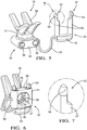
Figures 1 and 2 are 3D views of electric cable bundles wrapped to a fixation device as per the invention. -
Figures 3 and 4 present a leg member of said fixation device and a magnified view of a male half of a positioning feature. -
Figures 5, 6 and 7 present a head member of said fixation device with a view on a female half of the positioning feature and of a locking key. -
Figures 8 and 9 present the orientation and assembly of said fixation device. -
Figures 10 and 11 present locking of said fixation device. -
Figures 12, 13 and 14 present steps of a method to assemble a bundle of cables with a fixation member. -
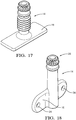
Figures 15, 16 ,17 and 18 present alternative embodiments of the support members and of the leg members. -
Figures 19 and 20 present a leg extension member using a similar concept as the support member. - A general presentation of typical bundles wrapped and fixed to
fixation devices 10 as per the invention is shown offigures 1 and 2 , a large bundle requiring twoties 12 onfigure 1 and, a smaller bundle requiring only onetie 12 onfigure 2 . Thefixation devices 10 are plastic moulded and comprise aleg member 14 provided at a lower end with an integralfixation foot member 16 and with anindependent head member 18 arranged at an opposite top end of theleg 14 and there fixed by akey 20. - More in details in reference to the
figures 3 and 4 , thehead 18 andleg 14 members further define together a complementary positioning feature 22 enabling orientation of thehead 18 and insertion and locking onto theleg member 14. - At the other end, the
foot 16 is typically planar having an upper face wherefrom extends theleg 14 and an under face adapted to be arranged in surface contact against a wall of the structure. Thefoot 16 is provided with fixation features such as screw orrivets holes 24 or with an under face arranged for being glued onto said wall. Also, theleg 14 integrally extends from thefoot 16 perpendicular, or parallel as shown onfigure 18 . - Using the general orientation of the
figures 3 and 4 , theleg 14 upwardly extends about a main axis X, in a cylindrical pillar toward amale half 26 of saidpositioning feature 22, saidmale half 26 comprising anannular groove 28 surrounding the cylindrical pillar and amale teeth wheel 30 forming the very end of said upwardleg 14. - The
head member 18 shown onfigures 5, 6 and 7 comprises integrally moulded abody 31 defining afemale half 32 of saidpositioning feature 22 and abundle support feature 34 that, in the embodiments presented comprises V-like members adapted to receive the cables. Alternatively, other shapes of support features 34 U-like or O-like members exists. Thefemale half 32 of saidpositioning feature 22 comprises acylindrical recess 36 and twoparallel key holes 38 defined in thebody 31. - The
cylindrical recess 36 comprises a smooth portion forming a female cylinder ofrevolution 40 arranged proximal the opening of therecess 36 in a bottom face of the body and, a toothed portion forming afemale teeth wheel 42 complementary to themale teeth wheel 30 of the leg and arranged proximal the inner bottom end of therecess 36. The male 30 and female 42 wheels are complementary as having the same number of teeth, teeth having the same module, the male 30 wheel being adapted to register into the female 42 teeth. - The two
key holes 38 are parallel to each other and they extend through the body perpendicular and tangent to saidcylindrical recess 36. Each of theholes 38 open in a front faces 44 of thebody 31 and an oppositerear face 46. Said holes 38 being tangent to therecess 36, they open in diametrically opposed area of thesmooth cylinder 40. - Complementary to the
key holes 38, the key 20 has U-shape comprising a holdingportion 48 from the opposite ends of which twoarms 50 extend parallel to each other toward adistant locking end 52. The twoarms 50 having the same offset as the twokey holes 38, the key 20 can be inserted therein and, as shown on the bottom view offigure 6 , the locking ends 52 protrude in therear face 46 of thebody 31 and also, the middle portion of thearms 50 radially protrude in thesmooth cylinder 40 of therecess 36. - Moreover, the
arms 50 have a circular section up to the locking ends 52 which section is only semi-circular. Being reduced by half, said locking ends section provide resilient properties to said ends 52 which therefore can slightly bent toward each other's. The removed, or non-moulded, portions of said reduced section are the halves of the arms that are facing each other's or, that are on the "inside" of the arms. Also, each lockingend 52 is provided with atooth 54 formed at the very end of thearm 50 and magnified onfigure 7 , saidtooth 54 outwardly protruding opposite the reduced section area and defining anabrupt shoulder 56 transition to the arm transverse to the main axis X. - The embodiment presented further comprises a
flexible link 56 extending from a side face of thehead member 18 to the holdingportion 48 of the key 20, said link being integrally moulded with thehead 18 and the key 20. - Alternatively, the fixation device could be without link, the
head 18 and the key 20 being separately moulded. - The assembly of the
fixation device 10 is shown onfigures 8 and 9 and is done by complementary arrangement of thehead 18 over theleg 20 and more precisely by insertion of thefemale half 32 of the positioning feature of thehead 18 over themale half 26 of the positioning feature of the leg member. Prior to the insertion of the male teeth wheel 30 into thefemale teeth wheel 42, as shown onfigure 8 , thehead member 18 is angularly oriented relative to theleg 20, the increment of orientation being the number of teeth of the wheels. It has been found interesting tomould 28 teeth for an incrementing step of 13°, although a larger step of 22.5° can be obtained by moulding only 16 teeth per wheel. This orientation characteristic enables to place and fix theleg members 14 first on the wall of the structure then, arrange thehead members 18 in accordance with the routing of the wire harness. Also, it enables an adjustment of the orientation of the head so that said head does not generate side forces of the wires. - Once properly oriented, the
head 18 is inserted,figure 9 , on the end of theleg 14, thesmooth cylinder 40 of the head facing thegroove 28 below the male teeth wheel. Then thehead 18 is locked in position by insertion of thearms 50 of the key 20 into the key holes 38. The middle portion of thearms 50 that radially protrudes in the smooth cylinder, indeed protrude in thegroove 28 preventing axial X disengagement of thehead 18. Also, theteeth 54 outwardly protruding from the arms have urged theends 52 to slightly bend inwardly during the insertion of thearms 50 in thekey holes 38 and, when said insertion is complete theteeth 54 exit theholes 38 and, the ends 52 resiliently bent back outwardly to a rest position where saidteeth 54 automatically register against the edges of said holes,figures 10 and 11 , on therear face 46 of the head, thus preventing disengagement of the key 20 without a volunteer inward bending action on said key arm ends 52. - The teeth wheels enable angular orientation of the head over the leg and forbid a change in orientation; the middle of the arms protruding in the groove forbid disengagement of the head and, the key arm ends 52 lock the assembly in a single configuration. In an alternative not represented, the wheels are provided tooth-less enabling the
head member 18 to angularly rotate an self adjust in the direction required. - Once the harness is positioned in the bundle support features 34, the
tie 12 is inserted in a slot arranged in thebody 31 of thehead member 18,figures 12, 13 and 14 and, saidtie 12 is wrapped around the harness and tightened with a special tool not shown. In a preferred method of arrangement, the key 20 is inserted after the bundle is wrapped by atie 12. Following this step sequence enables the user to adjust the angular orientation of the head member without having to disengage the key. - As shown on the
figures 15 to 18 , thepositioning feature 22 can be applied on a plurality of embodiments wherein the head is provided with two or three V-like support members, using one or twoties 12, wherein thefoot 16 and theleg 14 members can be coplanar or perpendicular, the leg itself being long asfigure 1 or short,figure 2 . To avoid damages on the cables, soft cushions are arranged on the V-like support and enable to protect the bundle from direct contact with the head member or with a sharp edge. - Also, as shown of
figures 19 and 20 , aleg extension member 58 can be made and inserted between theleg 14 and thehead 18 in order to extend the height of the leg member.Such extension member 58 comprises afemale half 32 of thepositioning feature 22 for complementary arrangement at the end of the leg and, amale half 26 for receiving thehead member 18. Integrally moulded with itsown key 20, saidextension member 58 is also fixed in position relative to the leg member. -
- X
- main axis
- 10
- fixation device
- 12
- tie
- 14
- leg member
- 16
- foot member
- 18
- head member
- 20
- key
- 22
- positioning feature
- 24
- holes
- 26
- male half of the positioning feature
- 28
- hollow - groove
- 30
- male teeth wheel
- 31
- body of the head member
- 32
- female half of the positioning feature
- 34
- support feature
- 36
- recess
- 38
- key holes
- 40
- smooth cylinder of revolution
- 42
- female teeth wheel
- 44
- front face of the head body
- 46
- rear face of the head body
- 48
- key holding portion
- 50
- key arms
- 52
- locking end of the arm
- 54
- tooth
- 56
- link
- 58
- leg extension member
Claims (24)
- Fixation device (10) for holding in place a bundle of cables onto a structure, said device (10) comprising a head member (18) arranged on a leg member (14), said leg member (14) extending from a fixation foot (16) for fixing the device (10) on said structure to said head member (18) for positioning and fixing said bundle,
characterised in that
the fixation device (10) further comprises a positioning feature (22) enabling a plurality of relative positioning of the head member (18) and the leg member (14). - Fixation device (10) as claimed in the preceding claim wherein the leg member (14) and the head member (18) are distinct members, the positioning feature (22) further enabling complementary engagement of said distinct members.
- Fixation device (10) as claimed in the claim 2 wherein said positioning feature (22) includes a male-female engagement.
- Fixation device (10) as claimed in claim 3 wherein said male-female engagement a comprises teeth connections.
- Fixation device (10) as claimed in claim 4 wherein said positioning feature (22) comprises between 10 to30 teeth, preferably 16, enabling a discrete selection of 10 to 30 relative positions, preferably 16.
- Fixation device (10) as claimed in any one of the claims 2 to 5 wherein the head member (18) and the leg member (14) are both plastic moulded.
- Fixation device (10) as claimed in any one of the claims 2 to 6 further comprising a key (20) preventing disengagement of the head member (18) and the leg member (14).
- Fixation device (10) as claimed in claim 7 wherein said key (20) comprises an arm (50) inserted in a key hole (38) of the head member (18) and engaged in a hollow (28) arranged on the leg member (14).
- Fixation device (10) as claimed in claim 8 wherein the hollow (28) is an annular groove (28) surrounding the leg member (14), the key hole (38) being tangent to said groove (28) so the arm (50) registers in both the hole (38) and the groove (28) preventing disengagement of the head member (18) from the leg member (14).
- Fixation device (10) as claimed in claim 9 wherein the key (20) comprises a holding portion (48) from which extends said arm (50).
- Fixation device (10) as claimed in any of the claims 7 to 10 wherein the key (20) is provided a snap-fit tooth (54) adapted to engage a complementary indent feature when the key (20) is in place in the key hole.
- Fixation device(10) as claimed in the combination of claims 8 and 11 wherein, when the key (20) is in place the end of the arm (50) protrudes outside the key hole (38), the snap-fit tooth (54) being arranged at said protruding end of the arm (50) to engage the edge of the opening of the key hole (38) forming said complementary indent feature.
- Fixation device (10) as claimed in any one of the claims 11 or 12 wherein the arm (50) is elastically flexible and wherein, removal of the key (20) is done by elastically bending of the arm (50) removing the snap fit tooth (54) from said complementary indent feature.
- Fixation device (10) as claimed in any of the claims 7 to 13 wherein the key (20) comprises a second arm (50) extending parallel to the first arm (50), the two arms (50) engaging in two different key holes (38) provided in the head member (18), said two holes (38) being both parallel to each other's and tangent to the groove (28) in diametrically opposed areas.
- Fixation device (10) as claimed in the combination of claims 11 and 14 wherein each of the two arms (50) is provided with a locking device, the removal of the key (20) involving elastically bending both arms (50) toward each other's.
- Fixation device (10) as claimed in any one of the claims 7 to 15 wherein the key (20) in plastic moulded.
- Fixation device (10) as claimed in any one of the claims 7 to 16 further comprising a flexible link (56) extending from the head member (18) to the key (20).
- Fixation device (10) as claimed in claim 17 wherein the head member (18), the link (56) and the key (20) are integrally moulded.
- Fixation device (10) as claimed in any one of the preceding claims further comprising a tie (12) inserted in a slot provided in the head member (18), or in the leg member (14), said tie (12) being adapted to be looped and tightened around the bundle.
- Method of arranging and fixing a bundle of cables on a structure, said method comprising the following steps:a) providing a fixation device (10) as claimed in any one of the preceding claims;b) fixing the leg member (14) onto the structure via fixation means such as rivets, bondage or screws;c) arranging the head member (18) in a chosen position relative to the leg member (14).
- Method as claimed in claim 20 wherein the fixation device (10) provided at step a) comprises distinct leg member (14) and head member (18) and wherein the arranging step c) comprises:d) orienting the head member (18) relative to the leg member (14) in the chosen position and,e) engaging the head (18) member on the leg member (14).
- Method as claimed in claim 21 wherein the fixation device (10) provided at step a) comprises the key (20) of any one of the claims 7 to 17, the method further comprising the step:f) locking the head member (18) onto the leg member (14) by arranging the key (20).
- Method as claimed in claim 22 wherein the fixation device (10) provided at step a) further comprising the tie (12) of claim 17, the method further comprising the following step:g) inserting the tie (12) in a slot provided in the head member (18) and looping and tightening said tie (12) around the bundle.
- Method as claimed in the combination of claims 22 and 23 wherein the inserting step g) is done before the locking step f).
Priority Applications (3)
| Application Number | Priority Date | Filing Date | Title |
|---|---|---|---|
| EP16204819.3A EP3336989B1 (en) | 2016-12-16 | 2016-12-16 | Cable fixation device |
| US15/826,891 US10428976B2 (en) | 2016-12-16 | 2017-11-30 | Cable fixation device |
| CN201711339791.0A CN108206495B (en) | 2016-12-16 | 2017-12-14 | Cable fixing device and method |
Applications Claiming Priority (1)
| Application Number | Priority Date | Filing Date | Title |
|---|---|---|---|
| EP16204819.3A EP3336989B1 (en) | 2016-12-16 | 2016-12-16 | Cable fixation device |
Publications (2)
| Publication Number | Publication Date |
|---|---|
| EP3336989A1 true EP3336989A1 (en) | 2018-06-20 |
| EP3336989B1 EP3336989B1 (en) | 2020-07-22 |
Family
ID=57796117
Family Applications (1)
| Application Number | Title | Priority Date | Filing Date |
|---|---|---|---|
| EP16204819.3A Active EP3336989B1 (en) | 2016-12-16 | 2016-12-16 | Cable fixation device |
Country Status (3)
| Country | Link |
|---|---|
| US (1) | US10428976B2 (en) |
| EP (1) | EP3336989B1 (en) |
| CN (1) | CN108206495B (en) |
Families Citing this family (10)
| Publication number | Priority date | Publication date | Assignee | Title |
|---|---|---|---|---|
| DE202016102746U1 (en) * | 2016-05-23 | 2017-08-25 | Hellermanntyton Gmbh | Non-contact holder for a binding material |
| MX2019011204A (en) | 2017-03-21 | 2020-01-23 | Hubbell Inc | Non-conductive support stands. |
| CN111727137A (en) * | 2018-01-02 | 2020-09-29 | 沃尔沃卡车集团 | Holder device comprising a carrier and a spacer and method for producing a spacer |
| USD897527S1 (en) * | 2018-05-04 | 2020-09-29 | Karl Storz Se & Co. Kg | Fixation handle |
| FR3094065B1 (en) * | 2019-03-22 | 2022-07-15 | Safran Aerosystems | Device for holding a bundle of cables |
| CN110425422B (en) * | 2019-07-03 | 2022-02-22 | 中国商用飞机有限责任公司 | Adjustable fixing support |
| CN112563993B (en) * | 2020-12-07 | 2022-04-29 | 中国商用飞机有限责任公司 | Branching device and installation method thereof |
| EP4131687A1 (en) | 2021-08-06 | 2023-02-08 | HellermannTyton GmbH | Edge clip |
| CN113483157A (en) | 2021-08-06 | 2021-10-08 | 海尔曼太通(无锡)电器配件有限公司 | Quick assembly disassembly pipe clamp |
| FR3130088A1 (en) * | 2021-12-02 | 2023-06-09 | Amphenol - Air Lb | Device for securing an object to a structure |
Citations (6)
| Publication number | Priority date | Publication date | Assignee | Title |
|---|---|---|---|---|
| GB973481A (en) * | 1960-01-06 | 1964-10-28 | Insuloid Mfg Company Ltd | Improvements in or relating to mounting clips |
| EP0459904A1 (en) * | 1990-06-01 | 1991-12-04 | Dassault-Aviation | Modular assembly for holding electric cables |
| DE202005015875U1 (en) * | 2005-10-07 | 2007-02-15 | S-Fasteners Gmbh | Holder arrangement for cables or similar with adjustable turn-stop positions |
| WO2012120321A1 (en) * | 2011-03-10 | 2012-09-13 | Bombardier Inc. | Standoff device and method of installation of harness |
| DE102011120936A1 (en) * | 2011-12-14 | 2013-06-20 | Diehl Comfort Modules GmbH | Cable support device for airplane, has cable module that is directly connected with base module through attachment module, where cable and attachment modules are arranged in form-locking connection with base module by securing portion |
| US8829353B2 (en) * | 2012-08-20 | 2014-09-09 | S-Fasteners Gmbh | Cable-support arrangement |
Family Cites Families (10)
| Publication number | Priority date | Publication date | Assignee | Title |
|---|---|---|---|---|
| FR2225396B1 (en) | 1973-04-10 | 1978-02-10 | Electro Refractaire | |
| US4319425A (en) * | 1980-05-01 | 1982-03-16 | Shine Thomas M | Gravity operated track |
| US20130119208A1 (en) * | 2004-04-30 | 2013-05-16 | Hellermanntyton Corporation | Fir tree mount for cable ties |
| DE102009045557A1 (en) | 2009-10-12 | 2011-04-14 | Robert Bosch Gmbh | Mounting arrangement for a sensor arrangement and sensor arrangement |
| FR2981491B1 (en) | 2011-10-13 | 2013-11-22 | Sitour | DEVICE FOR FIXING AN INFORMATION MEDIUM |
| TWI437558B (en) | 2012-08-23 | 2014-05-11 | Cal Comp Electronics & Comm Co | Metal shock absorber, assembly of metal shock absorber and media recording unit and media recording device |
| US9528535B2 (en) * | 2013-03-11 | 2016-12-27 | Illinois Tool Works Inc. | Multifunctional adaptor |
| ES2707730T3 (en) * | 2013-09-13 | 2019-04-04 | Te Connectivity Corp | Adjustable cable managers |
| CA2928410A1 (en) | 2013-10-22 | 2015-04-30 | Tagnetics, Inc. | Temperature sensor for retail environments |
| CN205583563U (en) | 2016-03-29 | 2016-09-14 | 江苏恒铭达航空设备有限公司 | Cable fixing frame for helicopter |
-
2016
- 2016-12-16 EP EP16204819.3A patent/EP3336989B1/en active Active
-
2017
- 2017-11-30 US US15/826,891 patent/US10428976B2/en active Active
- 2017-12-14 CN CN201711339791.0A patent/CN108206495B/en active Active
Patent Citations (6)
| Publication number | Priority date | Publication date | Assignee | Title |
|---|---|---|---|---|
| GB973481A (en) * | 1960-01-06 | 1964-10-28 | Insuloid Mfg Company Ltd | Improvements in or relating to mounting clips |
| EP0459904A1 (en) * | 1990-06-01 | 1991-12-04 | Dassault-Aviation | Modular assembly for holding electric cables |
| DE202005015875U1 (en) * | 2005-10-07 | 2007-02-15 | S-Fasteners Gmbh | Holder arrangement for cables or similar with adjustable turn-stop positions |
| WO2012120321A1 (en) * | 2011-03-10 | 2012-09-13 | Bombardier Inc. | Standoff device and method of installation of harness |
| DE102011120936A1 (en) * | 2011-12-14 | 2013-06-20 | Diehl Comfort Modules GmbH | Cable support device for airplane, has cable module that is directly connected with base module through attachment module, where cable and attachment modules are arranged in form-locking connection with base module by securing portion |
| US8829353B2 (en) * | 2012-08-20 | 2014-09-09 | S-Fasteners Gmbh | Cable-support arrangement |
Also Published As
| Publication number | Publication date |
|---|---|
| US10428976B2 (en) | 2019-10-01 |
| CN108206495A (en) | 2018-06-26 |
| US20180172182A1 (en) | 2018-06-21 |
| EP3336989B1 (en) | 2020-07-22 |
| CN108206495B (en) | 2020-03-03 |
Similar Documents
| Publication | Publication Date | Title |
|---|---|---|
| EP3336989B1 (en) | Cable fixation device | |
| US11686409B2 (en) | Hanger for mounting cables | |
| US9719300B2 (en) | Ladder rung bracket assembly | |
| JP6602956B2 (en) | Blind hole mount | |
| CA2927386C (en) | Mounting device for tubular elements | |
| US8534614B2 (en) | Device for holding systems and aircraft or spacecraft | |
| US20180163899A1 (en) | Insert for mounting multiple cables in cable hanger | |
| EP3072748A1 (en) | Protector, assembly of wire with protector, and assembling method therefor | |
| US11125358B2 (en) | Stackable brackets for microducts and cables | |
| US20160121822A1 (en) | Harness clip and system for clipping wiring harness | |
| CN112771296A (en) | Combined fixing clip | |
| US20190115736A1 (en) | Electrical box cable connector | |
| EP3503325A1 (en) | Wire harness module | |
| US20100200263A1 (en) | Electrical junction box for tool-less installation of power cables | |
| JP2008178353A (en) | Nesting-preventing instrument for utility pole | |
| EP3688357B1 (en) | Cable clips | |
| GB2447489A (en) | A retaining device using a cable tie having a secondary anchorage | |
| KR200388148Y1 (en) | Wire harness fix clip | |
| JP4138429B2 (en) | Manufacturing method of wire harness | |
| US20160339852A1 (en) | Method and apparatus for securing a vehicle wiring harness | |
| WO2020041132A1 (en) | Fastening members | |
| KR20170138965A (en) | Stud clip for fixing bus-bar | |
| JP2005341776A (en) | Belt clamp | |
| JP2017143707A (en) | Band clip and wiring harness with the same | |
| KR20170138972A (en) | Stud clip for fixing bus-bar |
Legal Events
| Date | Code | Title | Description |
|---|---|---|---|
| PUAI | Public reference made under article 153(3) epc to a published international application that has entered the european phase |
Free format text: ORIGINAL CODE: 0009012 |
|
| STAA | Information on the status of an ep patent application or granted ep patent |
Free format text: STATUS: THE APPLICATION HAS BEEN PUBLISHED |
|
| AK | Designated contracting states |
Kind code of ref document: A1 Designated state(s): AL AT BE BG CH CY CZ DE DK EE ES FI FR GB GR HR HU IE IS IT LI LT LU LV MC MK MT NL NO PL PT RO RS SE SI SK SM TR |
|
| AX | Request for extension of the european patent |
Extension state: BA ME |
|
| STAA | Information on the status of an ep patent application or granted ep patent |
Free format text: STATUS: REQUEST FOR EXAMINATION WAS MADE |
|
| 17P | Request for examination filed |
Effective date: 20181220 |
|
| RBV | Designated contracting states (corrected) |
Designated state(s): AL AT BE BG CH CY CZ DE DK EE ES FI FR GB GR HR HU IE IS IT LI LT LU LV MC MK MT NL NO PL PT RO RS SE SI SK SM TR |
|
| GRAP | Despatch of communication of intention to grant a patent |
Free format text: ORIGINAL CODE: EPIDOSNIGR1 |
|
| STAA | Information on the status of an ep patent application or granted ep patent |
Free format text: STATUS: GRANT OF PATENT IS INTENDED |
|
| INTG | Intention to grant announced |
Effective date: 20191205 |
|
| GRAS | Grant fee paid |
Free format text: ORIGINAL CODE: EPIDOSNIGR3 |
|
| GRAJ | Information related to disapproval of communication of intention to grant by the applicant or resumption of examination proceedings by the epo deleted |
Free format text: ORIGINAL CODE: EPIDOSDIGR1 |
|
| GRAL | Information related to payment of fee for publishing/printing deleted |
Free format text: ORIGINAL CODE: EPIDOSDIGR3 |
|
| STAA | Information on the status of an ep patent application or granted ep patent |
Free format text: STATUS: REQUEST FOR EXAMINATION WAS MADE |
|
| GRAR | Information related to intention to grant a patent recorded |
Free format text: ORIGINAL CODE: EPIDOSNIGR71 |
|
| STAA | Information on the status of an ep patent application or granted ep patent |
Free format text: STATUS: GRANT OF PATENT IS INTENDED |
|
| INTC | Intention to grant announced (deleted) | ||
| INTG | Intention to grant announced |
Effective date: 20200511 |
|
| GRAA | (expected) grant |
Free format text: ORIGINAL CODE: 0009210 |
|
| STAA | Information on the status of an ep patent application or granted ep patent |
Free format text: STATUS: THE PATENT HAS BEEN GRANTED |
|
| AK | Designated contracting states |
Kind code of ref document: B1 Designated state(s): AL AT BE BG CH CY CZ DE DK EE ES FI FR GB GR HR HU IE IS IT LI LT LU LV MC MK MT NL NO PL PT RO RS SE SI SK SM TR |
|
| REG | Reference to a national code |
Ref country code: GB Ref legal event code: FG4D |
|
| REG | Reference to a national code |
Ref country code: CH Ref legal event code: EP |
|
| REG | Reference to a national code |
Ref country code: DE Ref legal event code: R096 Ref document number: 602016040318 Country of ref document: DE |
|
| REG | Reference to a national code |
Ref country code: AT Ref legal event code: REF Ref document number: 1294290 Country of ref document: AT Kind code of ref document: T Effective date: 20200815 |
|
| REG | Reference to a national code |
Ref country code: IE Ref legal event code: FG4D |
|
| REG | Reference to a national code |
Ref country code: LT Ref legal event code: MG4D |
|
| REG | Reference to a national code |
Ref country code: AT Ref legal event code: MK05 Ref document number: 1294290 Country of ref document: AT Kind code of ref document: T Effective date: 20200722 |
|
| PG25 | Lapsed in a contracting state [announced via postgrant information from national office to epo] |
Ref country code: NO Free format text: LAPSE BECAUSE OF FAILURE TO SUBMIT A TRANSLATION OF THE DESCRIPTION OR TO PAY THE FEE WITHIN THE PRESCRIBED TIME-LIMIT Effective date: 20201022 Ref country code: AT Free format text: LAPSE BECAUSE OF FAILURE TO SUBMIT A TRANSLATION OF THE DESCRIPTION OR TO PAY THE FEE WITHIN THE PRESCRIBED TIME-LIMIT Effective date: 20200722 Ref country code: BG Free format text: LAPSE BECAUSE OF FAILURE TO SUBMIT A TRANSLATION OF THE DESCRIPTION OR TO PAY THE FEE WITHIN THE PRESCRIBED TIME-LIMIT Effective date: 20201022 Ref country code: PT Free format text: LAPSE BECAUSE OF FAILURE TO SUBMIT A TRANSLATION OF THE DESCRIPTION OR TO PAY THE FEE WITHIN THE PRESCRIBED TIME-LIMIT Effective date: 20201123 Ref country code: ES Free format text: LAPSE BECAUSE OF FAILURE TO SUBMIT A TRANSLATION OF THE DESCRIPTION OR TO PAY THE FEE WITHIN THE PRESCRIBED TIME-LIMIT Effective date: 20200722 Ref country code: GR Free format text: LAPSE BECAUSE OF FAILURE TO SUBMIT A TRANSLATION OF THE DESCRIPTION OR TO PAY THE FEE WITHIN THE PRESCRIBED TIME-LIMIT Effective date: 20201023 Ref country code: SE Free format text: LAPSE BECAUSE OF FAILURE TO SUBMIT A TRANSLATION OF THE DESCRIPTION OR TO PAY THE FEE WITHIN THE PRESCRIBED TIME-LIMIT Effective date: 20200722 Ref country code: HR Free format text: LAPSE BECAUSE OF FAILURE TO SUBMIT A TRANSLATION OF THE DESCRIPTION OR TO PAY THE FEE WITHIN THE PRESCRIBED TIME-LIMIT Effective date: 20200722 Ref country code: LT Free format text: LAPSE BECAUSE OF FAILURE TO SUBMIT A TRANSLATION OF THE DESCRIPTION OR TO PAY THE FEE WITHIN THE PRESCRIBED TIME-LIMIT Effective date: 20200722 Ref country code: FI Free format text: LAPSE BECAUSE OF FAILURE TO SUBMIT A TRANSLATION OF THE DESCRIPTION OR TO PAY THE FEE WITHIN THE PRESCRIBED TIME-LIMIT Effective date: 20200722 |
|
| PG25 | Lapsed in a contracting state [announced via postgrant information from national office to epo] |
Ref country code: IS Free format text: LAPSE BECAUSE OF FAILURE TO SUBMIT A TRANSLATION OF THE DESCRIPTION OR TO PAY THE FEE WITHIN THE PRESCRIBED TIME-LIMIT Effective date: 20201122 Ref country code: LV Free format text: LAPSE BECAUSE OF FAILURE TO SUBMIT A TRANSLATION OF THE DESCRIPTION OR TO PAY THE FEE WITHIN THE PRESCRIBED TIME-LIMIT Effective date: 20200722 Ref country code: PL Free format text: LAPSE BECAUSE OF FAILURE TO SUBMIT A TRANSLATION OF THE DESCRIPTION OR TO PAY THE FEE WITHIN THE PRESCRIBED TIME-LIMIT Effective date: 20200722 Ref country code: RS Free format text: LAPSE BECAUSE OF FAILURE TO SUBMIT A TRANSLATION OF THE DESCRIPTION OR TO PAY THE FEE WITHIN THE PRESCRIBED TIME-LIMIT Effective date: 20200722 |
|
| PG25 | Lapsed in a contracting state [announced via postgrant information from national office to epo] |
Ref country code: NL Free format text: LAPSE BECAUSE OF FAILURE TO SUBMIT A TRANSLATION OF THE DESCRIPTION OR TO PAY THE FEE WITHIN THE PRESCRIBED TIME-LIMIT Effective date: 20200722 |
|
| REG | Reference to a national code |
Ref country code: DE Ref legal event code: R097 Ref document number: 602016040318 Country of ref document: DE |
|
| PG25 | Lapsed in a contracting state [announced via postgrant information from national office to epo] |
Ref country code: RO Free format text: LAPSE BECAUSE OF FAILURE TO SUBMIT A TRANSLATION OF THE DESCRIPTION OR TO PAY THE FEE WITHIN THE PRESCRIBED TIME-LIMIT Effective date: 20200722 Ref country code: SM Free format text: LAPSE BECAUSE OF FAILURE TO SUBMIT A TRANSLATION OF THE DESCRIPTION OR TO PAY THE FEE WITHIN THE PRESCRIBED TIME-LIMIT Effective date: 20200722 Ref country code: CZ Free format text: LAPSE BECAUSE OF FAILURE TO SUBMIT A TRANSLATION OF THE DESCRIPTION OR TO PAY THE FEE WITHIN THE PRESCRIBED TIME-LIMIT Effective date: 20200722 Ref country code: DK Free format text: LAPSE BECAUSE OF FAILURE TO SUBMIT A TRANSLATION OF THE DESCRIPTION OR TO PAY THE FEE WITHIN THE PRESCRIBED TIME-LIMIT Effective date: 20200722 Ref country code: EE Free format text: LAPSE BECAUSE OF FAILURE TO SUBMIT A TRANSLATION OF THE DESCRIPTION OR TO PAY THE FEE WITHIN THE PRESCRIBED TIME-LIMIT Effective date: 20200722 Ref country code: IT Free format text: LAPSE BECAUSE OF FAILURE TO SUBMIT A TRANSLATION OF THE DESCRIPTION OR TO PAY THE FEE WITHIN THE PRESCRIBED TIME-LIMIT Effective date: 20200722 |
|
| PLBE | No opposition filed within time limit |
Free format text: ORIGINAL CODE: 0009261 |
|
| STAA | Information on the status of an ep patent application or granted ep patent |
Free format text: STATUS: NO OPPOSITION FILED WITHIN TIME LIMIT |
|
| PG25 | Lapsed in a contracting state [announced via postgrant information from national office to epo] |
Ref country code: AL Free format text: LAPSE BECAUSE OF FAILURE TO SUBMIT A TRANSLATION OF THE DESCRIPTION OR TO PAY THE FEE WITHIN THE PRESCRIBED TIME-LIMIT Effective date: 20200722 |
|
| 26N | No opposition filed |
Effective date: 20210423 |
|
| PG25 | Lapsed in a contracting state [announced via postgrant information from national office to epo] |
Ref country code: SK Free format text: LAPSE BECAUSE OF FAILURE TO SUBMIT A TRANSLATION OF THE DESCRIPTION OR TO PAY THE FEE WITHIN THE PRESCRIBED TIME-LIMIT Effective date: 20200722 |
|
| REG | Reference to a national code |
Ref country code: CH Ref legal event code: PL |
|
| PG25 | Lapsed in a contracting state [announced via postgrant information from national office to epo] |
Ref country code: SI Free format text: LAPSE BECAUSE OF FAILURE TO SUBMIT A TRANSLATION OF THE DESCRIPTION OR TO PAY THE FEE WITHIN THE PRESCRIBED TIME-LIMIT Effective date: 20200722 Ref country code: MC Free format text: LAPSE BECAUSE OF FAILURE TO SUBMIT A TRANSLATION OF THE DESCRIPTION OR TO PAY THE FEE WITHIN THE PRESCRIBED TIME-LIMIT Effective date: 20200722 |
|
| REG | Reference to a national code |
Ref country code: BE Ref legal event code: MM Effective date: 20201231 |
|
| REG | Reference to a national code |
Ref country code: NL Ref legal event code: MP Effective date: 20200722 |
|
| PG25 | Lapsed in a contracting state [announced via postgrant information from national office to epo] |
Ref country code: LU Free format text: LAPSE BECAUSE OF NON-PAYMENT OF DUE FEES Effective date: 20201216 Ref country code: IE Free format text: LAPSE BECAUSE OF NON-PAYMENT OF DUE FEES Effective date: 20201216 |
|
| PG25 | Lapsed in a contracting state [announced via postgrant information from national office to epo] |
Ref country code: LI Free format text: LAPSE BECAUSE OF NON-PAYMENT OF DUE FEES Effective date: 20201231 Ref country code: CH Free format text: LAPSE BECAUSE OF NON-PAYMENT OF DUE FEES Effective date: 20201231 |
|
| PG25 | Lapsed in a contracting state [announced via postgrant information from national office to epo] |
Ref country code: TR Free format text: LAPSE BECAUSE OF FAILURE TO SUBMIT A TRANSLATION OF THE DESCRIPTION OR TO PAY THE FEE WITHIN THE PRESCRIBED TIME-LIMIT Effective date: 20200722 Ref country code: MT Free format text: LAPSE BECAUSE OF FAILURE TO SUBMIT A TRANSLATION OF THE DESCRIPTION OR TO PAY THE FEE WITHIN THE PRESCRIBED TIME-LIMIT Effective date: 20200722 Ref country code: CY Free format text: LAPSE BECAUSE OF FAILURE TO SUBMIT A TRANSLATION OF THE DESCRIPTION OR TO PAY THE FEE WITHIN THE PRESCRIBED TIME-LIMIT Effective date: 20200722 |
|
| PG25 | Lapsed in a contracting state [announced via postgrant information from national office to epo] |
Ref country code: MK Free format text: LAPSE BECAUSE OF FAILURE TO SUBMIT A TRANSLATION OF THE DESCRIPTION OR TO PAY THE FEE WITHIN THE PRESCRIBED TIME-LIMIT Effective date: 20200722 |
|
| PG25 | Lapsed in a contracting state [announced via postgrant information from national office to epo] |
Ref country code: BE Free format text: LAPSE BECAUSE OF NON-PAYMENT OF DUE FEES Effective date: 20201231 |
|
| PGFP | Annual fee paid to national office [announced via postgrant information from national office to epo] |
Ref country code: DE Payment date: 20221219 Year of fee payment: 7 |
|
| P01 | Opt-out of the competence of the unified patent court (upc) registered |
Effective date: 20230424 |
|
| PGFP | Annual fee paid to national office [announced via postgrant information from national office to epo] |
Ref country code: GB Payment date: 20231230 Year of fee payment: 8 |
|
| PGFP | Annual fee paid to national office [announced via postgrant information from national office to epo] |
Ref country code: FR Payment date: 20231229 Year of fee payment: 8 |