EP3336909A1 - Thermoelectric module - Google Patents
Thermoelectric module Download PDFInfo
- Publication number
- EP3336909A1 EP3336909A1 EP17168398.0A EP17168398A EP3336909A1 EP 3336909 A1 EP3336909 A1 EP 3336909A1 EP 17168398 A EP17168398 A EP 17168398A EP 3336909 A1 EP3336909 A1 EP 3336909A1
- Authority
- EP
- European Patent Office
- Prior art keywords
- electrode
- connection part
- thermoelectric
- extension direction
- thermoelectric module
- Prior art date
- Legal status (The legal status is an assumption and is not a legal conclusion. Google has not performed a legal analysis and makes no representation as to the accuracy of the status listed.)
- Granted
Links
Images






Classifications
-
- H—ELECTRICITY
- H10—SEMICONDUCTOR DEVICES; ELECTRIC SOLID-STATE DEVICES NOT OTHERWISE PROVIDED FOR
- H10N—ELECTRIC SOLID-STATE DEVICES NOT OTHERWISE PROVIDED FOR
- H10N19/00—Integrated devices, or assemblies of multiple devices, comprising at least one thermoelectric or thermomagnetic element covered by groups H10N10/00 - H10N15/00
- H10N19/101—Multiple thermocouples connected in a cascade arrangement
-
- H—ELECTRICITY
- H10—SEMICONDUCTOR DEVICES; ELECTRIC SOLID-STATE DEVICES NOT OTHERWISE PROVIDED FOR
- H10N—ELECTRIC SOLID-STATE DEVICES NOT OTHERWISE PROVIDED FOR
- H10N10/00—Thermoelectric devices comprising a junction of dissimilar materials, i.e. devices exhibiting Seebeck or Peltier effects
- H10N10/80—Constructional details
- H10N10/82—Interconnections
-
- F—MECHANICAL ENGINEERING; LIGHTING; HEATING; WEAPONS; BLASTING
- F25—REFRIGERATION OR COOLING; COMBINED HEATING AND REFRIGERATION SYSTEMS; HEAT PUMP SYSTEMS; MANUFACTURE OR STORAGE OF ICE; LIQUEFACTION SOLIDIFICATION OF GASES
- F25B—REFRIGERATION MACHINES, PLANTS OR SYSTEMS; COMBINED HEATING AND REFRIGERATION SYSTEMS; HEAT PUMP SYSTEMS
- F25B21/00—Machines, plants or systems, using electric or magnetic effects
- F25B21/02—Machines, plants or systems, using electric or magnetic effects using Peltier effect; using Nernst-Ettinghausen effect
-
- H—ELECTRICITY
- H10—SEMICONDUCTOR DEVICES; ELECTRIC SOLID-STATE DEVICES NOT OTHERWISE PROVIDED FOR
- H10D—INORGANIC ELECTRIC SEMICONDUCTOR DEVICES
- H10D89/00—Aspects of integrated devices not covered by groups H10D84/00 - H10D88/00
- H10D89/10—Integrated device layouts
- H10D89/105—Integrated device layouts adapted for thermal considerations
-
- H—ELECTRICITY
- H10—SEMICONDUCTOR DEVICES; ELECTRIC SOLID-STATE DEVICES NOT OTHERWISE PROVIDED FOR
- H10N—ELECTRIC SOLID-STATE DEVICES NOT OTHERWISE PROVIDED FOR
- H10N10/00—Thermoelectric devices comprising a junction of dissimilar materials, i.e. devices exhibiting Seebeck or Peltier effects
- H10N10/10—Thermoelectric devices comprising a junction of dissimilar materials, i.e. devices exhibiting Seebeck or Peltier effects operating with only the Peltier or Seebeck effects
- H10N10/17—Thermoelectric devices comprising a junction of dissimilar materials, i.e. devices exhibiting Seebeck or Peltier effects operating with only the Peltier or Seebeck effects characterised by the structure or configuration of the cell or thermocouple forming the device
-
- H—ELECTRICITY
- H10—SEMICONDUCTOR DEVICES; ELECTRIC SOLID-STATE DEVICES NOT OTHERWISE PROVIDED FOR
- H10N—ELECTRIC SOLID-STATE DEVICES NOT OTHERWISE PROVIDED FOR
- H10N10/00—Thermoelectric devices comprising a junction of dissimilar materials, i.e. devices exhibiting Seebeck or Peltier effects
- H10N10/80—Constructional details
-
- H—ELECTRICITY
- H10—SEMICONDUCTOR DEVICES; ELECTRIC SOLID-STATE DEVICES NOT OTHERWISE PROVIDED FOR
- H10N—ELECTRIC SOLID-STATE DEVICES NOT OTHERWISE PROVIDED FOR
- H10N10/00—Thermoelectric devices comprising a junction of dissimilar materials, i.e. devices exhibiting Seebeck or Peltier effects
- H10N10/80—Constructional details
- H10N10/81—Structural details of the junction
- H10N10/817—Structural details of the junction the junction being non-separable, e.g. being cemented, sintered or soldered
-
- H—ELECTRICITY
- H10—SEMICONDUCTOR DEVICES; ELECTRIC SOLID-STATE DEVICES NOT OTHERWISE PROVIDED FOR
- H10N—ELECTRIC SOLID-STATE DEVICES NOT OTHERWISE PROVIDED FOR
- H10N15/00—Thermoelectric devices without a junction of dissimilar materials; Thermomagnetic devices, e.g. using the Nernst-Ettingshausen effect
-
- H—ELECTRICITY
- H10—SEMICONDUCTOR DEVICES; ELECTRIC SOLID-STATE DEVICES NOT OTHERWISE PROVIDED FOR
- H10N—ELECTRIC SOLID-STATE DEVICES NOT OTHERWISE PROVIDED FOR
- H10N19/00—Integrated devices, or assemblies of multiple devices, comprising at least one thermoelectric or thermomagnetic element covered by groups H10N10/00 - H10N15/00
Definitions
- thermoelectric module more particularly to a thermoelectric module having a plurality of thermoelectric components having the same type of semiconductor material.
- thermoelectric module there are two types of thermoelectric modules.
- two ends of its thermoelectric component are connected with direct current (DC), and then a temperature difference occurs between these two ends.
- DC direct current
- This type of thermoelectric module can be applied to a mini refrigerator, a condensing dehumidifier, an insulation coasters and the like.
- thermoelectric module when two ends of its thermoelectric component have a temperature difference, these two ends generate direct current.
- This type of thermoelectric module can be applied to an energy recovering apparatus for recovering waste heat, a charger for a coaster and the like.
- thermoelectric components can be divided into two groups having different types of semiconductor material, wherein one group consists of multiple N-type thermoelectric components, and the other group consists of multiple P-type thermoelectric components.
- Each of the N-type thermoelectric components and the P-type thermoelectric components is placed alternately one after another, and the N-type thermoelectric components are electrically connected to P-type thermoelectric components.
- the thermoelectric components are either in serial connection or parallel connection.
- thermoelectric performance of the thermoelectric module is affected.
- the P-type thermoelectric component and the N-type thermoelectric component are naturally different in thermoelectric performance; it may result in inconsistent thermoelectric performance.
- the cost of manufacturing the conventional thermoelectric module is high because the manufacturer has to prepare the thermoelectric components in different materials.
- thermoelectric module having thermoelectric components that are made of the same material.
- thermoelectric module including a plurality of thermoelectric components, a first electrode and a second electrode.
- the thermoelectric components have the same type of semiconductor material.
- the first electrode includes a first parallel connection part and a first serial connection part.
- the plurality of thermoelectric components is electrically connected to the first parallel connection part, and each of the plurality of thermoelectric components is separated apart from one another.
- the first serial connection part is configured for being electrically connected to other electrical components.
- the plurality of thermoelectric components is electrically connected to the second electrode and located between the first parallel connection part and the second electrode.
- thermoelectric module since the thermoelectric components, which have the same type of semiconductor material, are in parallel connection through the parallel connection parts of the electrodes, so there is no need to spend time to arrange thermoelectric components made of different materials in an alternate manner during manufacturing process, and the thermoelectric module has consistent thermoelectric performance. In addition, there is no need to prepare thermoelectric components in different materials. As a result, the thermoelectric module of the present disclosure is easy to be manufactured.
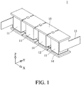
- thermoelectric module 1 is provided.
- the thermoelectric module 1 includes a plurality of thermoelectric components 11, a first electrode 12, a second electrode 13, a first base board 14 and a second base board 15.
- each thermoelectric component 11 has the same type of semiconductor material. Specifically, each thermoelectric component 11 is made of p-type semiconductor material, or alternatively, each thermoelectric component 11 is made of n-type semiconductor material. From the point of view of FIG. 1 , each thermoelectric component 11 has a first length along the X-axis, a second length along the Y-axis, and a third length along the Z-axis. The first length ranges from 1 millimeters (mm) to 60 mm. The second length ranges from 1 mm to 60 mm. The third length ranges from 0.6 mm to 25 mm. Each thermoelectric component 11 has two end surfaces having two edges equal to the first length and the other two edges equal to the second length.
- thermoelectric components 11 are spaced apart from one another, and the thermoelectric components 11 are in parallel connection through the first electrode 12 and the second electrode 13.
- the first base board 14 is disposed on the first electrode 12, and the second base board 15 is disposed on the second electrode 13.
- the first base board 14 and the second base board 15 both are made of, for example, ceramics, but the present disclosure is not limited thereto.
- both the first base board 14 and the second base board 15 may be made of a composite material composed of an outer layer made of ceramics and an inner layer made of metal, and the ceramics is in electrical insulation.
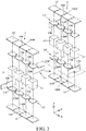
- FIG. 2 is a perspective view of the thermoelectric module in FIG. 1 and another thermoelectric module in serial connection
- FIG. 3 is an exploded view of the thermoelectric modules in FIG. 2
- the first electrode 12 includes a parallel connection part 12a and a serial connection part 12b which are integral with each other.
- the second electrode 13 includes a parallel connection part 13a and a serial connection part 13b which are integral with each other.
- the thermoelectric module 1 is in serial connection with another thermoelectric module 1'.
- thermoelectric components 11 are separated apart from one another, and the thermoelectric components 11 are in parallel connection through the parallel connection part 12a of the first electrode 12 and the parallel connection part 13a of the second electrode 13.
- the thermoelectric components 11 are located between the parallel connection part 12a of the first electrode 12 and the parallel connection part 13a of the second electrode 13.
- the thermoelectric module 1' includes a plurality of thermoelectric components 11', a first electrode 12', a second electrode 13', a first base board 14' and a second base board 15'.
- the thermoelectric components 11' have the same type of semiconductor material.
- the first electrode 12' includes a parallel connection part 12a' and a serial connection part 12b' which are integral with each other.
- the second electrode 13' includes a parallel connection part 13a' and a serial connection part 13b' which are integral with each other.
- the thermoelectric components 11' are in parallel connection through the parallel connection part 12a' of the first electrode 12' and the parallel connection part 13a' of the second electrode 13'.
- thermoelectric components 11' are located between the parallel connection part 12a' of the first electrode 12' and the parallel connection part 13a' of the second electrode 13'.
- the first base board 14' is disposed on the first electrode 12'
- the second base board 15' is disposed on the second electrode 13'.
- the serial connection part 13b of the second electrode 13 of the thermoelectric module 1 is electrically connected to the serial connection part 12b' of the first electrode 12' of the thermoelectric module 1', so that the thermoelectric module 1 and the thermoelectric module 1' are in serial connection.
- the direction of the arrangement of the thermoelectric components 11 of the thermoelectric module 1 is substantially the same as the direction of the arrangement of the thermoelectric components 11' of the thermoelectric module 1', and the direction of the arrangement of the thermoelectric modules 1 and 1' is substantially perpendicular to the direction of the arrangement of the thermoelectric components 11, but the present disclosure is not limited thereto.
- the direction of the arrangement of the thermoelectric modules 1 and 1' and the direction of the arrangement of the thermoelectric components 11 may be the same or have an angle over or less than 90 degrees therebetween.
- the parallel connection part 12a has a plurality of buffering holes 120 and a plurality of buffering notches 1200.
- the parallel connection part 13a has a plurality of buffering holes 130 and a plurality of buffering notches 1300.
- the buffering holes 120, the buffering notches 1200, the buffering holes 130 and the buffering notches 1300 are located between each thermoelectric component 11.
- the parallel connection part 12a' has a plurality of buffering holes 120' and a plurality of buffering notches 1200'.
- the parallel connection part 13a' has a plurality of buffering holes 130' and a plurality of buffering notches 1300'.
- the buffering holes 120', the buffering notches 1200', the buffering holes 130' and the buffering notches 1300' are located between each thermoelectric component 11'.
- the first base board 14 has a plurality of buffering holes 140 and a plurality of buffering notches 1400.
- the second base board 15 has a plurality of buffering holes 150 and a plurality of buffering notches 1500.
- the buffering holes 140, the buffering notches 1400, the buffering holes 150 and the buffering notches 1500 are located between each thermoelectric component 11.
- the first base board 14' has a plurality of buffering holes 140' and a plurality of buffering notches 1400'.
- the second base board 15' has a plurality of buffering holes 150' and a plurality of buffering notches 1500'.
- the buffering holes 140', the buffering notches 1400', the buffering holes 150' and the buffering notches 1500' are located between each thermoelectric component 11'.
- the buffering holes 120 and 130, the buffering notches 1200 and 1300, the buffering holes 140 and 150, and the buffering notches 1400 and 1500 are able to provide buffering to the thermoelectric module 1 while temperature is changing.
- the buffering holes 120' and 130', the buffering notches 1200' and 1300', the buffering holes 140' and 150', and the buffering notches 1400' and 1500' are able to provide buffering to the thermoelectric module 1' while temperature is changing. Accordingly, the thermoelectric module 1 and the thermoelectric module 1' are prevented from separating from each other due to temperature difference.
- each parallel connection part may only have one buffering hole and one buffering notch
- each base board may only have one buffering hole and one buffering notch.
- the buffering notches 1200 are located at two sides of the first electrode 12 opposite to each other, and the buffering holes 120 respectively correspond to and are located between the buffering notches 1200; in the first electrode 12', the buffering notches 1200' are located at two sides of the first electrode 12' opposite to each other, and the buffering holes 120' respectively correspond to and are located between the buffering notch 1200'; in the second electrode 13, the buffering notches 1300 are located at two sides of the second electrode 13 opposite to each other, and the buffering holes 130 respectively correspond to and are located between the buffering notches 1300; and in the second electrode 13', the buffering notches 1300' are located at two sides of the second electrode 13' opposite to each other, and buffering holes 130' respectively correspond to and are located between the buffering notches 1300'.
- the buffering notches 1400 are located at two sides of the first base board 14 opposite to each other, and the buffering holes 140 respectively correspond to and are located between the buffering notches 1400; and in the first base board 14', the buffering notches 1400' are located at two sides of the first base board 14' opposite to each other, and the buffering holes 140' respectively correspond to and are located between the buffering notches 1400'.
- the buffering notches 1500 are located at two sides of the second base board 15 opposite to each other, and the buffering holes 150 respectively correspond to and are located between the buffering notches 1500; and in the second base board 15', the buffering notches 1500' are located at two sides of the second base board 15' opposite to each other, and the buffering holes 150' respectively correspond to and are located between the buffering notches 1500'.
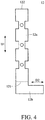
- FIG. 4 is a planar view of a semi-finished first electrode in FIG. 1 .
- FIG. 4 shows a semi-finished first electrode 12, and shapes of the semi-finished first electrode 12' and the semi-finished second electrodes 13 and 13' are similar to or the same as the shape of the semi-finished first electrode 12.
- the parallel connection part 12a has a first side 121 and a second side 122, and extends in a first extension direction D1.
- the first extension direction D1 is substantially parallel to a direction pointing from the first side 121 toward the second side 122.
- the thermoelectric components 11 are arranged along the first extension direction D1.
- the serial connection part 12b extends a distance from the first side 121 along the first extension direction D1, and then extends along a second extension direction D2.
- the second extension direction D2 is substantially parallel to the first side 121. That is, the serial connection part 12b has a first portion which extends from the first side 121 along the first extension direction D1, and a second portion which extends along the second extension direction D2 substantially parallel to the first side 121.
- the first side 121 is taken as a bend line, so the serial connection part 12b is able to be bent toward the second electrode 13 at the first side 121.
- the first electrode 12 is finished. That is, during the manufacturing process of the first electrode 12, the first electrode 12 is a whole sheet, and then some parts of the first electrode 12 are being cut out, and then the first electrode 12 is being bent.
- FIG. 5 is a top view of a thermoelectric module connected to another thermoelectric module according to another embodiment of the disclosure
- FIG. 6 is a side view of the thermoelectric modules in FIG. 5
- FIG. 7 is a planar view of a semi-finished first electrode in FIG. 6 .
- a thermoelectric module 2 and a thermoelectric module 2' are provided.
- the thermoelectric modules 2 and 2' are similar to the thermoelectric modules 1 and 1'.
- the thermoelectric components 21 are located between the first electrode 22 and the second electrode 23, and are in parallel connection through the first electrodes 22 and the second electrode 23.
- thermoelectric components 21' are located between the first electrode 22' and the second electrode 23', and are in parallel connection through the first electrode 22' and the second electrode 23'.
- the first electrode 22 and the second electrode 23' are electrically connected to each other so that the thermoelectric module 2 and the thermoelectric module 2 are in serial connection.
- FIG. 7 shows a semi-finished first electrode 22, and it is noted that shapes of the semi-finished first electrode 22' and the semi-finished second electrodes 23 and 23' are similar to or the same as the shape of the semi-finished first electrode 22.
- the first electrode 22 includes a parallel connection part 22a and a serial connection part 22b.
- the parallel connection part 22a and the serial connection part 22b are integral with each other.
- the parallel connection part 22a has a first side 221, a second side 222 and a third side 223.
- the first side 221 and the second side 222 are opposite to each other, and the third side 223 is located between the first side 221 and the second side 222.
- the parallel connection part 22a extends along a first extension direction D1 which is substantially parallel to a direction pointing from the first side 221 toward the second side 222.
- the thermoelectric components 21 are arranged along the first extension direction D1.
- the serial connection part 22b extends a distance from the third side 223 along a second extension direction D2.
- the second extension direction D2 is substantially parallel to the first side 221.
- the third side 223 is taken as a bend line, so the serial connection part 22b is able to be bent toward the second electrode 23 at the third side 223.
- the serial connection part 22b has another bend line 22b0 substantially parallel to the third side 223.
- the serial connection part 22b is able to be bent at the bend line 22b0, so that a part of the serial connection part 22b is able to be bent away from the thermoelectric component 21. That is, during the manufacturing process of the first electrode 22, the first electrode 22 is a whole sheet, and then some parts of the first electrode 22 are being cut out, and then the first electrode 22 is being bent.
- the serial connection part 22b is connected to an end part of the third side 223, but the present disclosure is not limited thereto. In some embodiments, the serial connection part 22b may be connected to a middle part of the third side 223 or a part close to the middle part of the third side 223.
- FIG. 8 is a top view of a thermoelectric module connected to another thermoelectric module according to yet another embodiment of the disclosure
- FIG. 9 is a side view of the thermoelectric modules in FIG. 8
- FIG. 10 is a planar view of a semi-finished first electrode in FIG. 9
- a thermoelectric module 3 and a thermoelectric module 3' are provided.
- the thermoelectric modules 3 and 3' are similar to the thermoelectric modules 2 and 2' in FIG. 6 .
- the thermoelectric components 31 are located between the first electrode 32 and the second electrode 33, and are in parallel connection through the first electrode 32 and the second electrode 33.
- thermoelectric components 31 are located between the first electrode 32' and the second electrode 33', and are in parallel connection through the first electrode 32' and the second electrode 33'.
- the first electrode 32 and the second electrode 33' are electrically connected to each other so that the thermoelectric module 3 and the thermoelectric module 3' are in serial connection.
- the shapes of the first electrodes 32 and 32' and the second electrodes 33 and 33' are different from that in FIG. 6 .
- FIG. 10 shows a semi-finished first electrode 32, and it is noted that the shapes of the semi-finished first electrode 32' and the semi-finished second electrodes 33 and 33' are similar to or the same as the shape of the semi-finished first electrode 32.
- the first electrode 32 includes a parallel connection part 32a and a serial connection part 32b.
- the parallel connection part 32a and the serial connection part 32b are integral with each other.
- the parallel connection part 32a has a first side 321, a second side 322 and a third side 323.
- the first side 321 and the second side 322 are opposite to each other, and the third side 323 is located between the first side 321 and the second side 322.
- the parallel connection part 32a extends along a first extension direction D1 substantially parallel to a direction pointing from the first side 321 toward the second side 322.
- the thermoelectric components 31 are arranged along the first extension direction D1.
- the serial connection part 32b extends a distance from the third side 323 along a second extension direction D2.
- the second extension direction D2 is substantially parallel to the first side 321.
- the third side 323 is taken as a bend line, so the serial connection part 32b is able to be bent toward the second electrode 33 at the third side 323. That is, during the manufacturing process of the first electrode 32, the first electrode 32 is a whole sheet, and then some parts of the first electrode 32 are being cut out, and then the first electrode 32 is being bent.
- the serial connection part 32b is connected to an end part of the third side 323, but the present disclosure is not limited thereto. In some embodiments, the serial connection part 32b may be connected to a middle part of the third side 323 or a part close to the middle part of the third side 323.
- FIG. 11 is a top view of a thermoelectric module connected to another thermoelectric module according to still another embodiment of the disclosure
- FIG. 12 is a side view of the thermoelectric modules in FIG. 11
- FIG. 13 is a planar view of a semi-finished first electrode in FIG. 12 .
- the thermoelectric components 41 are located between the first electrode 42 and the second electrode 43, and are in parallel connection through the first electrode 42 and the second electrode 43
- the thermoelectric components 41' are located between the first electrode 42' and the second electrode 43', and are in parallel connection through the first electrode 42' and the second electrode 43'.
- the first electrode 42 and the second electrode 43' are electrically connected to each other, so the thermoelectric module 4 and the thermoelectric module 4' are in serial connection.
- FIG. 13 shows a semi-finished first electrode 42. It is noted that the shapes of the semi-finished first electrode 42' and the semi-finished second electrodes 43 and 43' are similar to or the same as the shape of the semi-finished first electrode 42.
- the first electrode 42 includes a parallel connection part 42a and a serial connection part 42b.
- the parallel connection part 42a and the serial connection part 42b are integral with each other.
- the parallel connection part 42a has a first side 421 and a second side 422 opposite to each other.
- the parallel connection part 42a extends along a first extension direction D1 which is substantially parallel to a direction pointing from the first side 421 toward the second side 422.
- the thermoelectric components 41 are arranged along the first extension direction D1.
- a second extension direction D2 is substantially parallel to the first side 421.
- the serial connection part 42b extends a distance from the first side 421 along a third extension direction D3.
- the serial connection part 42b has a middle line 42b1 substantially parallel to the third extension direction D3.
- An acute angle ⁇ is between the second extension direction D2 and the third extension direction D3.
- the first side 421 is taken as a bend line, so the serial connection part 42b is able to be bent toward the second electrode 43 at the first side 421. That is, during the manufacturing process of the first electrode 42, the first electrode 42 is a whole sheet, and then some parts of the first electrode 42 are being cut out, and then the first electrode 42 is being bent.
- FIG. 14 is a top view of a thermoelectric module connected to another thermoelectric module according to still yet another embodiment of the disclosure
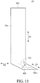
- FIG. 15 is a side view of the thermoelectric modules in FIG. 14
- FIG. 16 is a planar view of a semi-finished first electrode in FIG. 15 .
- a thermoelectric module 5 and a thermoelectric module 5' are provided.
- the thermoelectric modules 5 and 5' are similar to the thermoelectric modules 2 and 2' in FIG. 6 , but the direction of the arrangement of the thermoelectric modules 5 and 5' is substantially the same as the direction of the arrangement of the thermoelectric components 51.
- thermoelectric components 51 are located between the first electrode 52 and the second electrode 53, and are in parallel connection through the first electrode 52 and the second electrode 53.
- the thermoelectric components 51' are located between the first electrode 52' and the second electrode 53', and are in parallel connection through the first electrode 52' and the second electrode 53'.
- the first electrode 52 of the thermoelectric module 5 is electrically connected to the second electrode 53' of the thermoelectric module 5' so that the thermoelectric module 5 and the thermoelectric module 5' are in serial connection.
- FIG. 16 shows a semi-finished first electrode 52, and it is noted that the shapes of the semi-finished first electrode 52' and the semi-finished second electrodes 53 and 53' are similar to or the same as the shape of the semi-finished first electrode 52.
- the first electrode 52 includes a parallel connection part 52a and a serial connection part 52b.
- the parallel connection part 52a and the serial connection part 52b are integral with each other.
- the parallel connection part 52a has a first side 521 and a second side 522 opposite to each other.
- the parallel connection part 52a extends along a first extension direction D1 which is substantially parallel to a direction pointing from the first side 521 toward the second side 522.
- the thermoelectric components 51 are arranged along the first extension direction D1.
- the serial connection part 52b extends a distance from the first side 521 along the first extension direction D1.
- the first side 521 is taken as a bend line, so the serial connection part 52b is able to be bent toward the second electrode 53.
- the serial connection part 52b has another bend line 52b0 substantially parallel to the first side 521.
- the serial connection part 52b is able to be bent at the bend line 52b0, so that a part of the serial connection part 52b is able to be bent away from the thermoelectric component 51. That is, during the manufacturing process of the first electrode 52, the first electrode 52 is a whole sheet, and then some parts of the first electrode 52 are being cut out, and then the first electrode 52 is being bent.
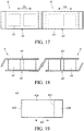
- FIG. 17 is a top view of a thermoelectric module connected to another thermoelectric module according to yet a further embodiment of the disclosure
- FIG. 18 is a side view of the thermoelectric modules in FIG. 17,
- FIG. 19 is a planar view of a semi-finished first electrode in FIG. 18 .
- a thermoelectric module 6 and a thermoelectric module 6' are provided.
- the thermoelectric modules 6 and 6' are similar to the thermoelectric modules 3 and 3' in FIG. 9 , but the direction of the arrangement of the thermoelectric modules 6 and 6' is substantially the same as the direction of the arrangement of the thermoelectric components 61.
- thermoelectric components 61 are located between the first electrode 62 and the second electrode 63, and are in parallel connection through the first electrode 62 and the second electrode 63.
- the thermoelectric components 61' are located between the first electrode 62' and the second electrode 63', and are in parallel connection through the first electrode 62' and the second electrode 63'.
- the first electrode 62 is electrically connected to the second electrode 63', so that the thermoelectric module 6 and the thermoelectric module 6' are in serial connection.
- FIG. 19 shows a semi-finished first electrode 62. It is noted that the shape of the semi-finished first electrode 62' and the semi-finished second electrodes 63 and 63' are similar to or the same as the shape of the semi-finished first electrode 62.
- the first electrode 62 includes a parallel connection part 62a and a serial connection part 62b.
- the parallel connection part 62a and the serial connection part 62b are integral with each other.
- the parallel connection part 62a has a first side 621 and a second side 622 opposite to each other.
- the parallel connection part 62a extends along a first extension direction D1 which is substantially parallel to a direction pointing from the first side 621 toward the second side 622.
- the thermoelectric components 61 are arranged along the first extension direction D1.
- the serial connection part 62b extends a distance from the first side 621 along the extension direction D1.
- the first side 621 is taken as a bend line, so the serial connection part 62b is able to be bent toward the second electrode 63. That is, during the manufacturing process of the first electrode 62, the first electrode 62 is a whole sheet, and then some parts of the first electrode 62 are being cut out, and then the first electrode 62 is being bent.
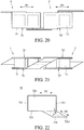
- FIG. 20 is a top view of a thermoelectric module connected to another thermoelectric module according to still yet a further embodiment of the disclosure
- FIG. 21 is a side view of the thermoelectric modules in FIG. 20
- FIG. 22 is a planar view of a semi-finished first electrode in FIG. 21 .
- a thermoelectric module 7 and a thermoelectric module 7' are provided.
- the thermoelectric modules 7 and 7' are similar to the thermoelectric modules 4 and 4' in FIG. 12 , but the direction of the arrangement of the thermoelectric modules 7 and 7' is substantially the same as the direction of the arrangement of the thermoelectric components 71.
- thermoelectric components 71 are located between the first electrode 72 and the second electrode 73, and are in parallel connection through the first electrode 72 and the second electrode 73.
- the thermoelectric components 71' are located between the first electrode 72' and the second electrode 73', and are in parallel connection through the first electrode 72' and the second electrode 73'.
- the first electrode 72 is electrically connected to the second electrode 73' so that the thermoelectric module 7 and the thermoelectric module 7' are in serial connection.
- the shapes of the first electrodes 72 and 72' and the second electrodes 73 and 73' are different from that in FIG. 12 .
- FIG. 22 shows a semi-finished first electrode 72. It is noted that the shapes of the semi-finished first electrode 72' and the semi-finished second electrodes 73 and 73' are similar to or the same as the shape of the semi-finished first electrode 72.
- the first electrode 72 includes a parallel connection part 72a and a serial connection part 72b.
- the parallel connection part 72a and the serial connection part 72b are integral with each other.
- the parallel connection part 72a has a first side 721, a second side 722 and a third side 723, the first side 721 and the second side 722 are opposite to each other, and the third side 723 is located between the first side 721 and the second side 722.
- the parallel connection part 72a extends along a first extension direction D1 which is substantially parallel to a direction pointing from the first side 721 toward the second side 722.
- the thermoelectric components 71 are arranged along the first extension direction D1.
- the serial connection part 72b extends a distance from the third side 723 along a fourth extension direction D4.
- the serial connection part 72b has a middle line 72b1 substantially parallel to the fourth extension direction D4.
- An acute angle ⁇ is between the first extension direction D1 and the fourth extension direction D4.
- the third side 723 is taken as a bend line, so the serial connection part 72b is able to be bent toward the second electrode 73. That is, during the manufacturing process of the first electrode 72, the first electrode 72 is a whole sheet, and then some parts of the first electrode 72 are being cut out, and then the first electrode 72 is being bent.
- the serial connection part 72b is connected to an end part of the third side 723, but the present disclosure is not limited thereto. In other embodiments, the serial connection part 72b may be connected to a middle part of the third side 723 or a part close to the middle part of the third side 723.
- FIG. 23 is a top view of a thermoelectric module connected to another thermoelectric module according to still yet another embodiment of the disclosure
- FIG. 24 is a side view of the thermoelectric modules in FIG. 23
- FIG. 25 is a planar view of a semi-finished first electrode in FIG. 24 .
- a thermoelectric module 8 and a thermoelectric module 8' are provided.
- the thermoelectric modules 8 and 8' are similar to the thermoelectric modules 1 and 1' in FIG. 2 , but the direction of the arrangement of the thermoelectric modules 8 and 8' is substantially the same as the thermoelectric components 81.
- thermoelectric components 81 are located between the first electrode 82 and the second electrode 83, and are in parallel connection through the first electrode 82 and the second electrode 83.
- the thermoelectric components 81' are located between the first electrode 82' and the second electrode 83', and are in parallel connection through the first electrode 82' and the second electrode 83'.
- the first electrode 82 is electrically connected to the second electrode 83', so the thermoelectric modules 8 and 8' are in serial connection.
- the shapes of the first electrodes 82 and 82' and the second electrodes 83 and 83' are different from that in FIG. 2 .
- FIG. 25 shows a semi-finished first electrode 82. It is noted that the shapes of the semi-finished first electrode 82' and the semi-finished second electrodes 83 and 83' are similar to or the same as the shape of the semi-finished first electrode 82.
- the first electrode 82 includes a parallel connection part 82a and a serial connection part 82b.
- the parallel connection part 82a and the serial connection part 82b are integral with each other.
- the parallel connection part 82a has a first side 821, a second side 822 and a third side 823, the first side 821 and the second side 822 are opposite to each other, and the third side 823 is located between the first side 821 and the second side 822.
- the parallel connection part 82a extends along a first extension direction D1 which is substantially parallel to a direction pointing from the first side 821 toward the second side 822. As shown in FIG. 23 , the thermoelectric components 81 are arranged along the first extension direction D1.
- the serial connection part 82b extends a distance from the third side 823 along a second extension direction D2, and then extends another distance along the first extension direction D1.
- a second extension direction D2 is substantially parallel to the first side 821.
- the third side 823 is taken as a bend line, so the serial connection part 82b is able to be bent toward the second electrode 83. That is, during the manufacturing process of the first electrode 82, the first electrode 82 is a whole sheet, and then some parts of the first electrode 82 are being cut out, and then the first electrode 82 is being bent.
- the serial connection part 82b is connected to a middle part of the third side 823, but the present disclosure is not limited thereto. In other embodiments, the serial connection part 82b may be connected to a middle part of the third side 823 or a part close to the end part of the third side 823.
- FIG. 26 is a side view of a thermoelectric module according to still yet further another embodiment of the disclosure.
- a thermoelectric module 9 is provided.
- the thermoelectric module 9 is similar to the thermoelectric module 1 in FIG. 2 .
- the thermoelectric components 91 are located between the first electrode 92 and the second electrode 93, and are in parallel connection through the first electrode 92 and the second electrode 93.
- the first base board 94 is disposed on the first electrode 92
- the second base board 95 is disposed on the second electrode 93.
- the thermoelectric module 9 further includes a plurality of supporting pillars 96 respectively located between each thermoelectric component 91.
- each supporting pillar 96 Two portions of each supporting pillar 96 are connected to the parallel connection part 92a of the first electrode 92 and the parallel connection part 93a of the second electrode 93.
- one end of each supporting pillar 96 penetrates through one of the buffering holes 920 of the parallel connection part 92a of the first electrode 92, and is embedded into one of the buffering holes 940 of the first base board 94 in order to be fixed to the first base board 94.
- the other end of each supporting pillar 96 penetrates through one of the buffering holes 930 of the parallel connection part 93a of the second electrode 93, and is embedded into one of the buffering holes 950 of the second base board 95 in order to be fixed to the second base board 95.
- each buffering hole 920 of the parallel connection part 92a of the first electrode 92 and an inner diameter of each buffering hole 930 of the parallel connection part 93a of the second electrode 93 both greater than an external diameter of each supporting pillar 96.
- the supporting pillars 96 are not in contact with the first electrode 92 and the second electrode 93.
- each supporting pillar 96 may protrude from the first base board 94; or the other end of each supporting pillar 96 may protrude from the second base board 95.
- two ends of each supporting pillar 96 may be respectively fixed to the parallel connection part 92a of the first electrode 92 and the parallel connection part 93a of the second electrode 93 via adhering or welding.
- each supporting pillar 96 may be fixed to the parallel connection part 92a of the first electrode 92, and the other end of each supporting pillar 96 may penetrate through one of the buffering holes 930 of the parallel connection part 93a of the second electrode 93 so as to be fixed to one of the buffering holes 950 of the second base board 95 without protruding from the second base board 95.
- each supporting pillar 96 penetrates through one of the buffering holes 920 of the parallel connection part 92a of the first electrode 92, and is fixed to one of the buffering holes 940 of the first base board 94, the other end of each supporting pillar 96 may protrude from or not protrude from the first base board 94 in order to be fixed to the parallel connection part 93a of the second electrode 93.
- thermoelectric module since the thermoelectric components, which have the same type of semiconductor material, are in parallel connection through the parallel connection parts of the electrodes, so there is no need to spend time to arrange thermoelectric components made of different materials in an alternate manner during manufacturing process, and the thermoelectric module has consistent thermoelectric performance. In addition, there is no need to prepare thermoelectric components in different materials. As a result, the thermoelectric module of one embodiment of the present disclosure is easy to be manufactured.
- thermoelectric module is able to be electrically connected to other electrical components via the serial connection part of the electrode, and the thermoelectric components are able to be in parallel connection via the parallel connection part of the electrode; thus, the electrode of the thermoelectric module is favorable for saving the time on the process of electrical connection.
Landscapes
- Engineering & Computer Science (AREA)
- Physics & Mathematics (AREA)
- Mechanical Engineering (AREA)
- Thermal Sciences (AREA)
- General Engineering & Computer Science (AREA)
- Cooling Or The Like Of Semiconductors Or Solid State Devices (AREA)
- Electric Clocks (AREA)
Abstract
Description
- The disclosure relates to a thermoelectric module, more particularly to a thermoelectric module having a plurality of thermoelectric components having the same type of semiconductor material.
- Regarding the development of thermoelectric module, there are two types of thermoelectric modules. In one type of the thermoelectric modules, two ends of its thermoelectric component are connected with direct current (DC), and then a temperature difference occurs between these two ends. This type of thermoelectric module can be applied to a mini refrigerator, a condensing dehumidifier, an insulation coasters and the like. In another type of thermoelectric module, when two ends of its thermoelectric component have a temperature difference, these two ends generate direct current. This type of thermoelectric module can be applied to an energy recovering apparatus for recovering waste heat, a charger for a coaster and the like.
- In conventional thermoelectric modules, the thermoelectric components can be divided into two groups having different types of semiconductor material, wherein one group consists of multiple N-type thermoelectric components, and the other group consists of multiple P-type thermoelectric components. Each of the N-type thermoelectric components and the P-type thermoelectric components is placed alternately one after another, and the N-type thermoelectric components are electrically connected to P-type thermoelectric components. However, the thermoelectric components are either in serial connection or parallel connection. During the manufacturing process of this type of thermoelectric module, it takes time to exactly place the P-type thermoelectric components and the N-type thermoelectric components in a correct arrangement. If there is any thermoelectric component being placed wrong, its thermoelectric performance will be different from the other thermoelectric components. As a result, the thermoelectric performance of the thermoelectric module is affected. In addition, the P-type thermoelectric component and the N-type thermoelectric component are naturally different in thermoelectric performance; it may result in inconsistent thermoelectric performance. Also, the cost of manufacturing the conventional thermoelectric module is high because the manufacturer has to prepare the thermoelectric components in different materials.
- The present disclosure provides a thermoelectric module having thermoelectric components that are made of the same material.
- One embodiment of the disclosure provides a thermoelectric module including a plurality of thermoelectric components, a first electrode and a second electrode. The thermoelectric components have the same type of semiconductor material. The first electrode includes a first parallel connection part and a first serial connection part. The plurality of thermoelectric components is electrically connected to the first parallel connection part, and each of the plurality of thermoelectric components is separated apart from one another. The first serial connection part is configured for being electrically connected to other electrical components. The plurality of thermoelectric components is electrically connected to the second electrode and located between the first parallel connection part and the second electrode.
- According to the thermoelectric module as discussed above, since the thermoelectric components, which have the same type of semiconductor material, are in parallel connection through the parallel connection parts of the electrodes, so there is no need to spend time to arrange thermoelectric components made of different materials in an alternate manner during manufacturing process, and the thermoelectric module has consistent thermoelectric performance. In addition, there is no need to prepare thermoelectric components in different materials. As a result, the thermoelectric module of the present disclosure is easy to be manufactured.
- The present disclosure will become better understood from the detailed description given hereinbelow and the accompanying drawings which are given by way of illustration only and thus are not limitative of the present disclosure and wherein:
-
FIG. 1 is a perspective view of a thermoelectric module according to one embodiment of the disclosure; -
FIG. 2 is a perspective view of the thermoelectric module inFIG. 1 and another thermoelectric module in serial connection; -
FIG. 3 is an exploded view of the thermoelectric modules inFIG. 2 ; -
FIG. 4 is a planar view of a semi-finished first electrode inFIG. 1 ; -
FIG. 5 is a top view of a thermoelectric module connected to another thermoelectric module according to another embodiment of the disclosure; -
FIG. 6 is a side view of the thermoelectric modules inFIG. 5 ; -
FIG. 7 is a planar view of a semi-finished first electrode inFIG. 6 ; -
FIG. 8 is a top view of a thermoelectric module connected to another thermoelectric module according to yet another embodiment of the disclosure; -
FIG. 9 is a side view of the thermoelectric modules inFIG. 8 ; -
FIG. 10 is a planar view of a semi-finished first electrode inFIG. 9 ; -
FIG. 11 is a top view of a thermoelectric module connected to another thermoelectric module according to still another embodiment of the disclosure; -
FIG. 12 is a side view of the thermoelectric modules inFIG. 11 ; -
FIG. 13 is a planar view of a semi-finished first electrode inFIG. 12 ; -
FIG. 14 is a top view of a thermoelectric module connected to another thermoelectric module according to still yet another embodiment of the disclosure; -
FIG. 15 is a side view of the thermoelectric modules inFIG. 14 ; -
FIG. 16 is a planar view of a semi-finished first electrode inFIG. 15 ; -
FIG. 17 is a top view of a thermoelectric module connected to another thermoelectric module according to yet a further embodiment of the disclosure; -
FIG. 18 is a side view of the thermoelectric modules inFIG. 17 ; -
FIG. 19 is a planar view of a semi-finished first electrode inFIG. 18 ; -
FIG. 20 is a top view of a thermoelectric module connected to another thermoelectric module according to still yet a further embodiment of the disclosure; -
FIG. 21 is a side view of the thermoelectric modules inFIG. 20 ; -
FIG. 22 is a planar view of a semi-finished first electrode inFIG. 21 ; -
FIG. 23 is a top view of a thermoelectric module connected to another thermoelectric module according to still yet another embodiment of the disclosure; -
FIG. 24 is a side view of the thermoelectric modules inFIG. 23 ; -
FIG. 25 is a planar view of a semi-finished first electrode inFIG. 24 ; and -
FIG. 26 is a side view of a thermoelectric module according to still yet further another embodiment of the disclosure. - In the following detailed description, for purposes of explanation, numerous specific details are set forth in order to provide a thorough understanding of the disclosed embodiments. It will be apparent, however, that one or more embodiments may be practiced without these specific details. In other instances, well-known structures and devices are schematically shown in order to simplify the drawing.
- The drawings may not be drawn to actual size or scale, some exaggerations may be necessary in order to emphasize basic structural relationships, while some are simplified for clarity of understanding, and the present disclosure is not limited thereto. It is allowed to have various adjustments under the spirit of the present disclosure. In the specification, the term "on" may be described as "one is located above another" or "one is in contact with another". In addition, the terms "top side", "bottom side", "above" and "below" are used to illustrate but limit the present disclosure. The term "substantially" is referred to the complete or nearly complete extent or degree of a structure, which means that it is allowable to have tolerance during manufacturing.
- Please refer to
FIG. 1 , which is a perspective view of a thermoelectric module according to one embodiment of the disclosure. In this embodiment, athermoelectric module 1 is provided. Thethermoelectric module 1 includes a plurality ofthermoelectric components 11, afirst electrode 12, asecond electrode 13, afirst base board 14 and asecond base board 15. - The
thermoelectric components 11 have the same type of semiconductor material. Specifically, eachthermoelectric component 11 is made of p-type semiconductor material, or alternatively, eachthermoelectric component 11 is made of n-type semiconductor material. From the point of view ofFIG. 1 , eachthermoelectric component 11 has a first length along the X-axis, a second length along the Y-axis, and a third length along the Z-axis. The first length ranges from 1 millimeters (mm) to 60 mm. The second length ranges from 1 mm to 60 mm. The third length ranges from 0.6 mm to 25 mm. Eachthermoelectric component 11 has two end surfaces having two edges equal to the first length and the other two edges equal to the second length. The two end surfaces are respectively electrically connected to thefirst electrode 12 and thesecond electrode 13. Thethermoelectric components 11 are spaced apart from one another, and thethermoelectric components 11 are in parallel connection through thefirst electrode 12 and thesecond electrode 13. Thefirst base board 14 is disposed on thefirst electrode 12, and thesecond base board 15 is disposed on thesecond electrode 13. In this embodiment, thefirst base board 14 and thesecond base board 15 both are made of, for example, ceramics, but the present disclosure is not limited thereto. In some embodiments, both thefirst base board 14 and thesecond base board 15 may be made of a composite material composed of an outer layer made of ceramics and an inner layer made of metal, and the ceramics is in electrical insulation. - Please refer to
FIG. 2 andFIG. 3 .FIG. 2 is a perspective view of the thermoelectric module inFIG. 1 and another thermoelectric module in serial connection, andFIG. 3 is an exploded view of the thermoelectric modules inFIG. 2 . In thethermoelectric module 1, thefirst electrode 12 includes aparallel connection part 12a and aserial connection part 12b which are integral with each other. Thesecond electrode 13 includes aparallel connection part 13a and aserial connection part 13b which are integral with each other. Thethermoelectric module 1 is in serial connection with another thermoelectric module 1'. - The
thermoelectric components 11 are separated apart from one another, and thethermoelectric components 11 are in parallel connection through theparallel connection part 12a of thefirst electrode 12 and theparallel connection part 13a of thesecond electrode 13. Thethermoelectric components 11 are located between theparallel connection part 12a of thefirst electrode 12 and theparallel connection part 13a of thesecond electrode 13. - The thermoelectric module 1' includes a plurality of thermoelectric components 11', a first electrode 12', a second electrode 13', a first base board 14' and a second base board 15'. The thermoelectric components 11' have the same type of semiconductor material. The first electrode 12' includes a
parallel connection part 12a' and aserial connection part 12b' which are integral with each other. The second electrode 13' includes aparallel connection part 13a' and aserial connection part 13b' which are integral with each other. The thermoelectric components 11' are in parallel connection through theparallel connection part 12a' of the first electrode 12' and theparallel connection part 13a' of the second electrode 13'. The thermoelectric components 11' are located between theparallel connection part 12a' of the first electrode 12' and theparallel connection part 13a' of the second electrode 13'. The first base board 14' is disposed on the first electrode 12', and the second base board 15' is disposed on the second electrode 13'. Theserial connection part 13b of thesecond electrode 13 of thethermoelectric module 1 is electrically connected to theserial connection part 12b' of the first electrode 12' of the thermoelectric module 1', so that thethermoelectric module 1 and the thermoelectric module 1' are in serial connection. In this embodiment, the direction of the arrangement of thethermoelectric components 11 of thethermoelectric module 1 is substantially the same as the direction of the arrangement of the thermoelectric components 11' of the thermoelectric module 1', and the direction of the arrangement of thethermoelectric modules 1 and 1' is substantially perpendicular to the direction of the arrangement of thethermoelectric components 11, but the present disclosure is not limited thereto. In some embodiments, the direction of the arrangement of thethermoelectric modules 1 and 1' and the direction of the arrangement of thethermoelectric components 11 may be the same or have an angle over or less than 90 degrees therebetween. - The
parallel connection part 12a has a plurality ofbuffering holes 120 and a plurality ofbuffering notches 1200. Theparallel connection part 13a has a plurality ofbuffering holes 130 and a plurality ofbuffering notches 1300. The buffering holes 120, thebuffering notches 1200, the buffering holes 130 and thebuffering notches 1300 are located between eachthermoelectric component 11. Theparallel connection part 12a' has a plurality of buffering holes 120' and a plurality of buffering notches 1200'. Theparallel connection part 13a' has a plurality of buffering holes 130' and a plurality of buffering notches 1300'. The buffering holes 120', the buffering notches 1200', the buffering holes 130' and the buffering notches 1300' are located between each thermoelectric component 11'. Thefirst base board 14 has a plurality ofbuffering holes 140 and a plurality ofbuffering notches 1400. Thesecond base board 15 has a plurality ofbuffering holes 150 and a plurality ofbuffering notches 1500. The buffering holes 140, thebuffering notches 1400, the buffering holes 150 and thebuffering notches 1500 are located between eachthermoelectric component 11. The first base board 14' has a plurality of buffering holes 140' and a plurality of buffering notches 1400'. The second base board 15' has a plurality of buffering holes 150' and a plurality of buffering notches 1500'. The buffering holes 140', the buffering notches 1400', the buffering holes 150' and the buffering notches 1500' are located between each thermoelectric component 11'. The buffering holes 120 and 130, thebuffering notches buffering notches thermoelectric module 1 while temperature is changing. The buffering holes 120' and 130', the buffering notches 1200' and 1300', the buffering holes 140' and 150', and the buffering notches 1400' and 1500' are able to provide buffering to the thermoelectric module 1' while temperature is changing. Accordingly, thethermoelectric module 1 and the thermoelectric module 1' are prevented from separating from each other due to temperature difference. It is noted that the present disclosure is not limited to the numbers of the buffering holes and the buffering notches in the aforementioned embodiment, in some embodiments, each parallel connection part may only have one buffering hole and one buffering notch, and each base board may only have one buffering hole and one buffering notch. - In this embodiment, in the
first electrode 12, thebuffering notches 1200 are located at two sides of thefirst electrode 12 opposite to each other, and the buffering holes 120 respectively correspond to and are located between thebuffering notches 1200; in the first electrode 12', the buffering notches 1200' are located at two sides of the first electrode 12' opposite to each other, and the buffering holes 120' respectively correspond to and are located between the buffering notch 1200'; in thesecond electrode 13, thebuffering notches 1300 are located at two sides of thesecond electrode 13 opposite to each other, and the buffering holes 130 respectively correspond to and are located between thebuffering notches 1300; and in the second electrode 13', the buffering notches 1300' are located at two sides of the second electrode 13' opposite to each other, and buffering holes 130' respectively correspond to and are located between the buffering notches 1300'. In this embodiment, on thefirst base board 14, thebuffering notches 1400 are located at two sides of thefirst base board 14 opposite to each other, and the buffering holes 140 respectively correspond to and are located between thebuffering notches 1400; and in the first base board 14', the buffering notches 1400' are located at two sides of the first base board 14' opposite to each other, and the buffering holes 140' respectively correspond to and are located between the buffering notches 1400'. In this embodiment, in thesecond base board 15, thebuffering notches 1500 are located at two sides of thesecond base board 15 opposite to each other, and the buffering holes 150 respectively correspond to and are located between thebuffering notches 1500; and in the second base board 15', the buffering notches 1500' are located at two sides of the second base board 15' opposite to each other, and the buffering holes 150' respectively correspond to and are located between the buffering notches 1500'. - Please refer to
FIG. 4 , which is a planar view of a semi-finished first electrode inFIG. 1 .FIG. 4 shows a semi-finishedfirst electrode 12, and shapes of the semi-finished first electrode 12' and the semi-finishedsecond electrodes 13 and 13' are similar to or the same as the shape of the semi-finishedfirst electrode 12. In the semi-finishedfirst electrode 12, theparallel connection part 12a has afirst side 121 and asecond side 122, and extends in a first extension direction D1. The first extension direction D1 is substantially parallel to a direction pointing from thefirst side 121 toward thesecond side 122. As shown inFIG. 1 , thethermoelectric components 11 are arranged along the first extension direction D1. Theserial connection part 12b extends a distance from thefirst side 121 along the first extension direction D1, and then extends along a second extension direction D2. The second extension direction D2 is substantially parallel to thefirst side 121. That is, theserial connection part 12b has a first portion which extends from thefirst side 121 along the first extension direction D1, and a second portion which extends along the second extension direction D2 substantially parallel to thefirst side 121. Thefirst side 121 is taken as a bend line, so theserial connection part 12b is able to be bent toward thesecond electrode 13 at thefirst side 121. As a result, thefirst electrode 12 is finished. That is, during the manufacturing process of thefirst electrode 12, thefirst electrode 12 is a whole sheet, and then some parts of thefirst electrode 12 are being cut out, and then thefirst electrode 12 is being bent. - Please refer to
FIG. 5, FIG. 6 andFIG. 7 .FIG. 5 is a top view of a thermoelectric module connected to another thermoelectric module according to another embodiment of the disclosure,FIG. 6 is a side view of the thermoelectric modules inFIG. 5 , andFIG. 7 is a planar view of a semi-finished first electrode inFIG. 6 . In this embodiment, athermoelectric module 2 and a thermoelectric module 2' are provided. Thethermoelectric modules 2 and 2' are similar to thethermoelectric modules 1 and 1'. Thethermoelectric components 21 are located between thefirst electrode 22 and thesecond electrode 23, and are in parallel connection through thefirst electrodes 22 and thesecond electrode 23. The thermoelectric components 21' are located between the first electrode 22' and the second electrode 23', and are in parallel connection through the first electrode 22' and the second electrode 23'. Thefirst electrode 22 and the second electrode 23' are electrically connected to each other so that thethermoelectric module 2 and thethermoelectric module 2 are in serial connection. However, in this embodiment, there are nobase boards first electrodes 22 and 22' and thesecond electrodes 23 and 23' are different from that inFIG. 2 .FIG. 7 shows a semi-finishedfirst electrode 22, and it is noted that shapes of the semi-finished first electrode 22' and the semi-finishedsecond electrodes 23 and 23' are similar to or the same as the shape of the semi-finishedfirst electrode 22. - The
first electrode 22 includes aparallel connection part 22a and a serial connection part 22b. Theparallel connection part 22a and the serial connection part 22b are integral with each other. Theparallel connection part 22a has afirst side 221, asecond side 222 and athird side 223. Thefirst side 221 and thesecond side 222 are opposite to each other, and thethird side 223 is located between thefirst side 221 and thesecond side 222. Theparallel connection part 22a extends along a first extension direction D1 which is substantially parallel to a direction pointing from thefirst side 221 toward thesecond side 222. As shown inFIG. 5 , thethermoelectric components 21 are arranged along the first extension direction D1. The serial connection part 22b extends a distance from thethird side 223 along a second extension direction D2. The second extension direction D2 is substantially parallel to thefirst side 221. Thethird side 223 is taken as a bend line, so the serial connection part 22b is able to be bent toward thesecond electrode 23 at thethird side 223. In addition, the serial connection part 22b has another bend line 22b0 substantially parallel to thethird side 223. The serial connection part 22b is able to be bent at the bend line 22b0, so that a part of the serial connection part 22b is able to be bent away from thethermoelectric component 21. That is, during the manufacturing process of thefirst electrode 22, thefirst electrode 22 is a whole sheet, and then some parts of thefirst electrode 22 are being cut out, and then thefirst electrode 22 is being bent. - In this embodiment, the serial connection part 22b is connected to an end part of the
third side 223, but the present disclosure is not limited thereto. In some embodiments, the serial connection part 22b may be connected to a middle part of thethird side 223 or a part close to the middle part of thethird side 223. - Please refer to
FIG. 8, FIG. 9 andFIG. 10 .FIG. 8 is a top view of a thermoelectric module connected to another thermoelectric module according to yet another embodiment of the disclosure,FIG. 9 is a side view of the thermoelectric modules inFIG. 8 , andFIG. 10 is a planar view of a semi-finished first electrode inFIG. 9 . In this embodiment, athermoelectric module 3 and a thermoelectric module 3' are provided. Thethermoelectric modules 3 and 3' are similar to thethermoelectric modules 2 and 2' inFIG. 6 . Thethermoelectric components 31 are located between thefirst electrode 32 and thesecond electrode 33, and are in parallel connection through thefirst electrode 32 and thesecond electrode 33. Thethermoelectric components 31 are located between the first electrode 32' and the second electrode 33', and are in parallel connection through the first electrode 32' and the second electrode 33'. Thefirst electrode 32 and the second electrode 33' are electrically connected to each other so that thethermoelectric module 3 and the thermoelectric module 3' are in serial connection. However, in this embodiment, the shapes of thefirst electrodes 32 and 32' and thesecond electrodes 33 and 33' are different from that inFIG. 6 . As shown inFIG. 10 , it shows a semi-finishedfirst electrode 32, and it is noted that the shapes of the semi-finished first electrode 32' and the semi-finishedsecond electrodes 33 and 33' are similar to or the same as the shape of the semi-finishedfirst electrode 32. - The
first electrode 32 includes aparallel connection part 32a and aserial connection part 32b. Theparallel connection part 32a and theserial connection part 32b are integral with each other. Theparallel connection part 32a has afirst side 321, asecond side 322 and athird side 323. Thefirst side 321 and thesecond side 322 are opposite to each other, and thethird side 323 is located between thefirst side 321 and thesecond side 322. Theparallel connection part 32a extends along a first extension direction D1 substantially parallel to a direction pointing from thefirst side 321 toward thesecond side 322. As shown inFIG. 8 , thethermoelectric components 31 are arranged along the first extension direction D1. Theserial connection part 32b extends a distance from thethird side 323 along a second extension direction D2. The second extension direction D2 is substantially parallel to thefirst side 321. Thethird side 323 is taken as a bend line, so theserial connection part 32b is able to be bent toward thesecond electrode 33 at thethird side 323. That is, during the manufacturing process of thefirst electrode 32, thefirst electrode 32 is a whole sheet, and then some parts of thefirst electrode 32 are being cut out, and then thefirst electrode 32 is being bent. - In this embodiment, the
serial connection part 32b is connected to an end part of thethird side 323, but the present disclosure is not limited thereto. In some embodiments, theserial connection part 32b may be connected to a middle part of thethird side 323 or a part close to the middle part of thethird side 323. - Please refer to
FIG. 11, FIG. 12 andFIG. 13 .FIG. 11 is a top view of a thermoelectric module connected to another thermoelectric module according to still another embodiment of the disclosure,FIG. 12 is a side view of the thermoelectric modules inFIG. 11 , andFIG. 13 is a planar view of a semi-finished first electrode inFIG. 12 . Thethermoelectric components 41 are located between thefirst electrode 42 and thesecond electrode 43, and are in parallel connection through thefirst electrode 42 and thesecond electrode 43, the thermoelectric components 41' are located between the first electrode 42' and the second electrode 43', and are in parallel connection through the first electrode 42' and the second electrode 43'. Thefirst electrode 42 and the second electrode 43' are electrically connected to each other, so thethermoelectric module 4 and the thermoelectric module 4' are in serial connection. However, in this embodiment, there are nobase boards first electrodes 42 and 42' and thesecond electrodes 43 and 43' are different from that inFIG. 2 .FIG. 13 shows a semi-finishedfirst electrode 42. It is noted that the shapes of the semi-finished first electrode 42' and the semi-finishedsecond electrodes 43 and 43' are similar to or the same as the shape of the semi-finishedfirst electrode 42. - The
first electrode 42 includes aparallel connection part 42a and aserial connection part 42b. Theparallel connection part 42a and theserial connection part 42b are integral with each other. Theparallel connection part 42a has afirst side 421 and asecond side 422 opposite to each other. Theparallel connection part 42a extends along a first extension direction D1 which is substantially parallel to a direction pointing from thefirst side 421 toward thesecond side 422. As shown inFIG. 11 , thethermoelectric components 41 are arranged along the first extension direction D1. A second extension direction D2 is substantially parallel to thefirst side 421. Theserial connection part 42b extends a distance from thefirst side 421 along a third extension direction D3. Theserial connection part 42b has a middle line 42b1 substantially parallel to the third extension direction D3. An acute angle θ is between the second extension direction D2 and the third extension direction D3. Thefirst side 421 is taken as a bend line, so theserial connection part 42b is able to be bent toward thesecond electrode 43 at thefirst side 421. That is, during the manufacturing process of thefirst electrode 42, thefirst electrode 42 is a whole sheet, and then some parts of thefirst electrode 42 are being cut out, and then thefirst electrode 42 is being bent. - Please refer to
FIG. 14, FIG. 15 and FIG. 16. FIG. 14 is a top view of a thermoelectric module connected to another thermoelectric module according to still yet another embodiment of the disclosure,FIG. 15 is a side view of the thermoelectric modules inFIG. 14, and FIG. 16 is a planar view of a semi-finished first electrode inFIG. 15 . In this embodiment, athermoelectric module 5 and a thermoelectric module 5' are provided. Thethermoelectric modules 5 and 5' are similar to thethermoelectric modules 2 and 2' inFIG. 6 , but the direction of the arrangement of thethermoelectric modules 5 and 5' is substantially the same as the direction of the arrangement of thethermoelectric components 51. Thethermoelectric components 51 are located between thefirst electrode 52 and thesecond electrode 53, and are in parallel connection through thefirst electrode 52 and thesecond electrode 53. The thermoelectric components 51' are located between the first electrode 52' and the second electrode 53', and are in parallel connection through the first electrode 52' and the second electrode 53'. Thefirst electrode 52 of thethermoelectric module 5 is electrically connected to the second electrode 53' of the thermoelectric module 5' so that thethermoelectric module 5 and the thermoelectric module 5' are in serial connection. However, in this embodiment, there are nobase boards first electrode 52 and 52' and thesecond electrodes 53 and 53' are different from that inFIG. 6 . As shown inFIG. 16 , it shows a semi-finishedfirst electrode 52, and it is noted that the shapes of the semi-finished first electrode 52' and the semi-finishedsecond electrodes 53 and 53' are similar to or the same as the shape of the semi-finishedfirst electrode 52. - The
first electrode 52 includes aparallel connection part 52a and aserial connection part 52b. Theparallel connection part 52a and theserial connection part 52b are integral with each other. Theparallel connection part 52a has afirst side 521 and asecond side 522 opposite to each other. Theparallel connection part 52a extends along a first extension direction D1 which is substantially parallel to a direction pointing from thefirst side 521 toward thesecond side 522. As shown inFIG. 14 , thethermoelectric components 51 are arranged along the first extension direction D1. Theserial connection part 52b extends a distance from thefirst side 521 along the first extension direction D1. Thefirst side 521 is taken as a bend line, so theserial connection part 52b is able to be bent toward thesecond electrode 53. In addition, theserial connection part 52b has another bend line 52b0 substantially parallel to thefirst side 521. Theserial connection part 52b is able to be bent at the bend line 52b0, so that a part of theserial connection part 52b is able to be bent away from thethermoelectric component 51. That is, during the manufacturing process of thefirst electrode 52, thefirst electrode 52 is a whole sheet, and then some parts of thefirst electrode 52 are being cut out, and then thefirst electrode 52 is being bent. - Please refer to
FIG. 17, FIG. 18 and FIG. 19. FIG. 17 is a top view of a thermoelectric module connected to another thermoelectric module according to yet a further embodiment of the disclosure,FIG. 18 is a side view of the thermoelectric modules inFIG. 17, and FIG. 19 is a planar view of a semi-finished first electrode inFIG. 18 . In this embodiment, athermoelectric module 6 and a thermoelectric module 6' are provided. Thethermoelectric modules 6 and 6' are similar to thethermoelectric modules 3 and 3' inFIG. 9 , but the direction of the arrangement of thethermoelectric modules 6 and 6' is substantially the same as the direction of the arrangement of thethermoelectric components 61. Thethermoelectric components 61 are located between thefirst electrode 62 and thesecond electrode 63, and are in parallel connection through thefirst electrode 62 and thesecond electrode 63. The thermoelectric components 61' are located between the first electrode 62' and the second electrode 63', and are in parallel connection through the first electrode 62' and the second electrode 63'. Thefirst electrode 62 is electrically connected to the second electrode 63', so that thethermoelectric module 6 and the thermoelectric module 6' are in serial connection. However, the shapes of thefirst electrodes 62 and 62' and thesecond electrodes 63 and 63' are different from that inFIG. 9 .FIG. 19 shows a semi-finishedfirst electrode 62. It is noted that the shape of the semi-finished first electrode 62' and the semi-finishedsecond electrodes 63 and 63' are similar to or the same as the shape of the semi-finishedfirst electrode 62. - The
first electrode 62 includes aparallel connection part 62a and aserial connection part 62b. Theparallel connection part 62a and theserial connection part 62b are integral with each other. Theparallel connection part 62a has afirst side 621 and asecond side 622 opposite to each other. Theparallel connection part 62a extends along a first extension direction D1 which is substantially parallel to a direction pointing from thefirst side 621 toward thesecond side 622. As shown inFIG. 17 , thethermoelectric components 61 are arranged along the first extension direction D1. Theserial connection part 62b extends a distance from thefirst side 621 along the extension direction D1. Thefirst side 621 is taken as a bend line, so theserial connection part 62b is able to be bent toward thesecond electrode 63. That is, during the manufacturing process of thefirst electrode 62, thefirst electrode 62 is a whole sheet, and then some parts of thefirst electrode 62 are being cut out, and then thefirst electrode 62 is being bent. - Please refer to
FIG. 20, FIG. 21 and FIG. 22. FIG. 20 is a top view of a thermoelectric module connected to another thermoelectric module according to still yet a further embodiment of the disclosure,FIG. 21 is a side view of the thermoelectric modules inFIG. 20, and FIG. 22 is a planar view of a semi-finished first electrode inFIG. 21 . In this embodiment, athermoelectric module 7 and a thermoelectric module 7' are provided. Thethermoelectric modules 7 and 7' are similar to thethermoelectric modules 4 and 4' inFIG. 12 , but the direction of the arrangement of thethermoelectric modules 7 and 7' is substantially the same as the direction of the arrangement of thethermoelectric components 71. Thethermoelectric components 71 are located between thefirst electrode 72 and thesecond electrode 73, and are in parallel connection through thefirst electrode 72 and thesecond electrode 73. The thermoelectric components 71' are located between the first electrode 72' and the second electrode 73', and are in parallel connection through the first electrode 72' and the second electrode 73'. Thefirst electrode 72 is electrically connected to the second electrode 73' so that thethermoelectric module 7 and the thermoelectric module 7' are in serial connection. However, in this embodiment, the shapes of thefirst electrodes 72 and 72' and thesecond electrodes 73 and 73' are different from that inFIG. 12 .FIG. 22 shows a semi-finishedfirst electrode 72. It is noted that the shapes of the semi-finished first electrode 72' and the semi-finishedsecond electrodes 73 and 73' are similar to or the same as the shape of the semi-finishedfirst electrode 72. - The
first electrode 72 includes aparallel connection part 72a and aserial connection part 72b. Theparallel connection part 72a and theserial connection part 72b are integral with each other. Theparallel connection part 72a has afirst side 721, asecond side 722 and athird side 723, thefirst side 721 and thesecond side 722 are opposite to each other, and thethird side 723 is located between thefirst side 721 and thesecond side 722. Theparallel connection part 72a extends along a first extension direction D1 which is substantially parallel to a direction pointing from thefirst side 721 toward thesecond side 722. As shown inFIG. 20 , thethermoelectric components 71 are arranged along the first extension direction D1. Theserial connection part 72b extends a distance from thethird side 723 along a fourth extension direction D4. Theserial connection part 72b has a middle line 72b1 substantially parallel to the fourth extension direction D4. An acute angle θ is between the first extension direction D1 and the fourth extension direction D4. Thethird side 723 is taken as a bend line, so theserial connection part 72b is able to be bent toward thesecond electrode 73. That is, during the manufacturing process of thefirst electrode 72, thefirst electrode 72 is a whole sheet, and then some parts of thefirst electrode 72 are being cut out, and then thefirst electrode 72 is being bent. - In this embodiment, the
serial connection part 72b is connected to an end part of thethird side 723, but the present disclosure is not limited thereto. In other embodiments, theserial connection part 72b may be connected to a middle part of thethird side 723 or a part close to the middle part of thethird side 723. - Please refer to
FIG. 23, FIG. 24 and FIG. 25. FIG. 23 is a top view of a thermoelectric module connected to another thermoelectric module according to still yet another embodiment of the disclosure,FIG. 24 is a side view of the thermoelectric modules inFIG. 23, and FIG. 25 is a planar view of a semi-finished first electrode inFIG. 24 . In this embodiment, athermoelectric module 8 and a thermoelectric module 8' are provided. Thethermoelectric modules 8 and 8' are similar to thethermoelectric modules 1 and 1' inFIG. 2 , but the direction of the arrangement of thethermoelectric modules 8 and 8' is substantially the same as thethermoelectric components 81. Thethermoelectric components 81 are located between thefirst electrode 82 and thesecond electrode 83, and are in parallel connection through thefirst electrode 82 and thesecond electrode 83. The thermoelectric components 81' are located between the first electrode 82' and the second electrode 83', and are in parallel connection through the first electrode 82' and the second electrode 83'. Thefirst electrode 82 is electrically connected to the second electrode 83', so thethermoelectric modules 8 and 8' are in serial connection. However, in this embodiment, the shapes of thefirst electrodes 82 and 82' and thesecond electrodes 83 and 83' are different from that inFIG. 2 .FIG. 25 shows a semi-finishedfirst electrode 82. It is noted that the shapes of the semi-finished first electrode 82' and the semi-finishedsecond electrodes 83 and 83' are similar to or the same as the shape of the semi-finishedfirst electrode 82. - The
first electrode 82 includes aparallel connection part 82a and aserial connection part 82b. Theparallel connection part 82a and theserial connection part 82b are integral with each other. Theparallel connection part 82a has afirst side 821, asecond side 822 and athird side 823, thefirst side 821 and thesecond side 822 are opposite to each other, and thethird side 823 is located between thefirst side 821 and thesecond side 822. Theparallel connection part 82a extends along a first extension direction D1 which is substantially parallel to a direction pointing from thefirst side 821 toward thesecond side 822. As shown inFIG. 23 , thethermoelectric components 81 are arranged along the first extension direction D1. Theserial connection part 82b extends a distance from thethird side 823 along a second extension direction D2, and then extends another distance along the first extension direction D1. A second extension direction D2 is substantially parallel to thefirst side 821. Thethird side 823 is taken as a bend line, so theserial connection part 82b is able to be bent toward thesecond electrode 83. That is, during the manufacturing process of thefirst electrode 82, thefirst electrode 82 is a whole sheet, and then some parts of thefirst electrode 82 are being cut out, and then thefirst electrode 82 is being bent. - In this embodiment, the
serial connection part 82b is connected to a middle part of thethird side 823, but the present disclosure is not limited thereto. In other embodiments, theserial connection part 82b may be connected to a middle part of thethird side 823 or a part close to the end part of thethird side 823. - Please refer to
FIG. 26. FIG. 26 is a side view of a thermoelectric module according to still yet further another embodiment of the disclosure. In this embodiment, a thermoelectric module 9 is provided. The thermoelectric module 9 is similar to thethermoelectric module 1 inFIG. 2 . In this embodiment, thethermoelectric components 91 are located between thefirst electrode 92 and the second electrode 93, and are in parallel connection through thefirst electrode 92 and the second electrode 93. Thefirst base board 94 is disposed on thefirst electrode 92, and thesecond base board 95 is disposed on the second electrode 93. In addition, the thermoelectric module 9 further includes a plurality of supportingpillars 96 respectively located between eachthermoelectric component 91. Two portions of each supportingpillar 96 are connected to the parallel connection part 92a of thefirst electrode 92 and theparallel connection part 93a of the second electrode 93. In this embodiment, one end of each supportingpillar 96 penetrates through one of the buffering holes 920 of the parallel connection part 92a of thefirst electrode 92, and is embedded into one of the buffering holes 940 of thefirst base board 94 in order to be fixed to thefirst base board 94. The other end of each supportingpillar 96 penetrates through one of the buffering holes 930 of theparallel connection part 93a of the second electrode 93, and is embedded into one of the buffering holes 950 of thesecond base board 95 in order to be fixed to thesecond base board 95. An inner diameter of eachbuffering hole 920 of the parallel connection part 92a of thefirst electrode 92 and an inner diameter of eachbuffering hole 930 of theparallel connection part 93a of the second electrode 93 both greater than an external diameter of each supportingpillar 96. The supportingpillars 96 are not in contact with thefirst electrode 92 and the second electrode 93. - However, the present disclosure is not limited to the aforementioned disposing way of the supporting
pillars 96. In some embodiments, one end of each supportingpillar 96 may protrude from thefirst base board 94; or the other end of each supportingpillar 96 may protrude from thesecond base board 95. In some embodiments, two ends of each supportingpillar 96 may be respectively fixed to the parallel connection part 92a of thefirst electrode 92 and theparallel connection part 93a of the second electrode 93 via adhering or welding. In some embodiments, one end of each supportingpillar 96 may be fixed to the parallel connection part 92a of thefirst electrode 92, and the other end of each supportingpillar 96 may penetrate through one of the buffering holes 930 of theparallel connection part 93a of the second electrode 93 so as to be fixed to one of the buffering holes 950 of thesecond base board 95 without protruding from thesecond base board 95. In some embodiments, one end of each supportingpillar 96 penetrates through one of the buffering holes 920 of the parallel connection part 92a of thefirst electrode 92, and is fixed to one of the buffering holes 940 of thefirst base board 94, the other end of each supportingpillar 96 may protrude from or not protrude from thefirst base board 94 in order to be fixed to theparallel connection part 93a of the second electrode 93. - According to the thermoelectric module as discussed above, since the thermoelectric components, which have the same type of semiconductor material, are in parallel connection through the parallel connection parts of the electrodes, so there is no need to spend time to arrange thermoelectric components made of different materials in an alternate manner during manufacturing process, and the thermoelectric module has consistent thermoelectric performance. In addition, there is no need to prepare thermoelectric components in different materials. As a result, the thermoelectric module of one embodiment of the present disclosure is easy to be manufactured.
- Furthermore, the thermoelectric module is able to be electrically connected to other electrical components via the serial connection part of the electrode, and the thermoelectric components are able to be in parallel connection via the parallel connection part of the electrode; thus, the electrode of the thermoelectric module is favorable for saving the time on the process of electrical connection.
- It will be apparent to those skilled in the art that various modifications and variations can be made to the present disclosure. It is intended that the specification and examples be considered as exemplary embodiments only, with a scope of the disclosure being indicated by the following claims and their equivalents.
Claims (15)
- A thermoelectric module (1), comprising:a plurality of thermoelectric components (11) having the same type of semiconductor material;a first electrode (12) comprising a first parallel connection part (12a) and a first serial connection part (12b), the plurality of thermoelectric components being electrically connected to the first parallel connection part and each of the plurality of thermoelectric components separated from one another, the first serial connection part configured for being electrically connected to other electrical components; anda second electrode (13), the plurality of thermoelectric components being electrically connected to the second electrode and located between the first parallel connection part and the second electrode.
- The thermoelectric module according to claim 1, wherein the first parallel connection part has at least one buffering hole (130) or at least one buffering notch (1300), and the at least one buffering hole or the at least one buffering notch is located between the plurality of thermoelectric components.
- The thermoelectric module according to claim 1, wherein the second electrode comprises a second parallel connection part (13a) and a second serial connection part (13b), the plurality of thermoelectric components is electrically connected to the second parallel connection part, and the second serial connection part is configured for being electrically connected to other electrical components.
- The thermoelectric module according to claim 1, further comprising at least one supporting pillar (96), the at least one supporting pillar located between the plurality of thermoelectric components, and two portions of the at least one supporting pillar being respectively disposed on the first parallel connection part of the first electrode and the second electrode.
- The thermoelectric module according to claim 1, further comprising a base board (14) disposed on the first electrode.
- The thermoelectric module according to claim 5, wherein the base board has at least one buffering hole (140) or at least one buffering notch (1400), located between the plurality of thermoelectric components.
- The thermoelectric module according to claim 1, wherein the first serial connection part and the first parallel connection part are integral with each other.
- The thermoelectric module according to claim 1, wherein the first parallel connection part has a first side (121) and a second side (122) opposite to each other, the first parallel connection part has a first extension direction (D1), the first extension direction is substantially parallel to a direction pointing from the first side toward the second side, the plurality of thermoelectric components is arranged along the first extension direction, and the first serial connection part extends from the first side.
- The thermoelectric module according to claim 8, wherein the first serial connection part extends from the first side along the first extension direction.
- The thermoelectric module according to claim 8, wherein the first serial connection part includes a first portion and a second portion connected to each other, the first portion extends from the first side along the first extension direction, the second portion extends along a second extension direction (D2), and the second extension direction is substantially parallel to the first side.
- The thermoelectric module according to claim 8, wherein there is a second extension direction substantially parallel to the first side, there is an acute angle (θ) between a third extension direction (D3) and the second extension direction, and the first serial connection part extends from the first side along the third extension direction.
- The thermoelectric module according to claim 1, wherein the first parallel connection part has a first side (221), a second side (222) and a third side (223), the first side and the second side are opposite to each other, the third side is located between the first side and the second side, the first parallel connection part extends along a first extension direction, the first extension direction is substantially parallel to a direction pointing from the first side toward the second side, the plurality of thermoelectric components is arranged along the first extension direction, and the first serial connection part extends from the third side.
- The thermoelectric module according to claim 12, wherein the first serial connection part extends from the third side along a second extension direction, and the second extension direction is substantially parallel to the first side.
- The thermoelectric module according to claim 12, wherein the first serial connection part includes a first portion and a second portion connected to each other, the first portion extends from the third side along a second extension direction, the second portion extends along the first extension direction, and the second extension direction is substantially parallel to the first side.
- The thermoelectric module according to claim 12, wherein the first serial connection part extends from the third side along a second extension direction, and there is an acute angle between the second extension direction and the first extension direction.
Applications Claiming Priority (1)
| Application Number | Priority Date | Filing Date | Title |
|---|---|---|---|
| TW105141653A TWI608638B (en) | 2016-12-15 | 2016-12-15 | Thermoelectric module |
Publications (2)
| Publication Number | Publication Date |
|---|---|
| EP3336909A1 true EP3336909A1 (en) | 2018-06-20 |
| EP3336909B1 EP3336909B1 (en) | 2019-06-19 |
Family
ID=58638762
Family Applications (1)
| Application Number | Title | Priority Date | Filing Date |
|---|---|---|---|
| EP17168398.0A Active EP3336909B1 (en) | 2016-12-15 | 2017-04-27 | Thermoelectric module |
Country Status (5)
| Country | Link |
|---|---|
| US (2) | US10648708B2 (en) |
| EP (1) | EP3336909B1 (en) |
| JP (1) | JP6505770B2 (en) |
| CN (1) | CN108231989B (en) |
| TW (1) | TWI608638B (en) |
Cited By (2)
| Publication number | Priority date | Publication date | Assignee | Title |
|---|---|---|---|---|
| EP3885674A1 (en) * | 2020-03-05 | 2021-09-29 | Weißhaar, Peter | Device for generating cold and power according to the peltier effect |
| WO2023192159A1 (en) * | 2022-04-01 | 2023-10-05 | Ats Ip, Llc | Modular package on package (pop) thermoelectric subassemblies for thermo electric generator devices |
Citations (4)
| Publication number | Priority date | Publication date | Assignee | Title |
|---|---|---|---|---|
| EP0506093A1 (en) * | 1991-03-27 | 1992-09-30 | Nippon Ferrofluidics Corporation | Thermoelectric conversion module and method of fabricating the same |
| US20100288325A1 (en) * | 2008-01-24 | 2010-11-18 | Universal Entertainment Corporation | Thermoelecric conversion module and connector for thermoelectric conversion element |
| EP2787545A1 (en) * | 2011-11-30 | 2014-10-08 | Nippon Thermostat Co., Ltd. | Thermoelectric conversion module |
| EP3054493A1 (en) * | 2013-09-30 | 2016-08-10 | Nippon Thermostat Co., Ltd. | Thermoelectric conversion module |
Family Cites Families (19)
| Publication number | Priority date | Publication date | Assignee | Title |
|---|---|---|---|---|
| JP4141415B2 (en) | 2004-06-30 | 2008-08-27 | 義臣 近藤 | Integrated parallel Peltier Seebeck element chip and manufacturing method thereof, integrated Peltier Seebeck element panel or sheet, and direct energy conversion system and energy transfer system |
| WO2006033875A2 (en) | 2004-09-09 | 2006-03-30 | Orobridge, Inc. | Thermoelectric devices with controlled current flow and related methods |
| JP4375249B2 (en) * | 2005-02-22 | 2009-12-02 | ヤマハ株式会社 | Thermoelectric module |
| JP2007073889A (en) | 2005-09-09 | 2007-03-22 | Chugoku Electric Power Co Inc:The | Thermoelectric converter |
| JP2008010764A (en) | 2006-06-30 | 2008-01-17 | Chugoku Electric Power Co Inc:The | Thermoelectric converter |
| JP4904193B2 (en) | 2007-04-26 | 2012-03-28 | 株式会社Kelk | Thermoelectric module |
| US20100147351A1 (en) | 2007-07-20 | 2010-06-17 | Universal Entertainment Corporation | Thermoelectric conversion module |
| TW200935635A (en) | 2008-02-15 | 2009-08-16 | Univ Nat Chiao Tung | Method of manufacturing nanometer-scale thermoelectric device |
| TWI360241B (en) | 2008-02-27 | 2012-03-11 | Raydium Semiconductor Corp | Chip with thermoelectric function |
| TWI415314B (en) * | 2009-02-05 | 2013-11-11 | Lg Chemical Ltd | Thermoelectric element module and manufacturing method |
| CN103250262B (en) | 2010-10-27 | 2017-04-05 | 巴斯夫欧洲公司 | Thermoelectric module and manufacturing method thereof |
| WO2012091048A1 (en) | 2010-12-28 | 2012-07-05 | 京セラ株式会社 | Thermoelectric conversion member |
| TWI605620B (en) * | 2011-12-30 | 2017-11-11 | 財團法人工業技術研究院 | Thermoelectric module and method of fabricating the same |
| WO2014062559A2 (en) | 2012-10-15 | 2014-04-24 | Alphabet Energy, Inc. | Structures and methods for multi-leg package thermoelectric devices |
| JP5670989B2 (en) * | 2012-11-20 | 2015-02-18 | アイシン高丘株式会社 | Thermoelectric module manufacturing method |
| JP6009382B2 (en) * | 2013-03-15 | 2016-10-19 | 日本サーモスタット株式会社 | Thermoelectric conversion module |
| KR102334301B1 (en) | 2014-07-24 | 2021-12-02 | 삼성전자주식회사 | Thermoelectric element, method of manufacturing the same and semiconductor device including the same |
| TWI557957B (en) * | 2014-12-08 | 2016-11-11 | 財團法人工業技術研究院 | Structure of thermoelectric module and fabricating method thereof |
| JP6453067B2 (en) | 2014-12-10 | 2019-01-16 | 日本サーモスタット株式会社 | Thermoelectric conversion module |
-
2016
- 2016-12-15 TW TW105141653A patent/TWI608638B/en active
-
2017
- 2017-03-31 US US15/476,893 patent/US10648708B2/en active Active
- 2017-03-31 CN CN201710206276.9A patent/CN108231989B/en active Active
- 2017-04-14 JP JP2017080551A patent/JP6505770B2/en active Active
- 2017-04-27 EP EP17168398.0A patent/EP3336909B1/en active Active
-
2020
- 2020-04-02 US US16/838,792 patent/US10955174B2/en active Active
Patent Citations (4)
| Publication number | Priority date | Publication date | Assignee | Title |
|---|---|---|---|---|
| EP0506093A1 (en) * | 1991-03-27 | 1992-09-30 | Nippon Ferrofluidics Corporation | Thermoelectric conversion module and method of fabricating the same |
| US20100288325A1 (en) * | 2008-01-24 | 2010-11-18 | Universal Entertainment Corporation | Thermoelecric conversion module and connector for thermoelectric conversion element |
| EP2787545A1 (en) * | 2011-11-30 | 2014-10-08 | Nippon Thermostat Co., Ltd. | Thermoelectric conversion module |
| EP3054493A1 (en) * | 2013-09-30 | 2016-08-10 | Nippon Thermostat Co., Ltd. | Thermoelectric conversion module |
Cited By (2)
| Publication number | Priority date | Publication date | Assignee | Title |
|---|---|---|---|---|
| EP3885674A1 (en) * | 2020-03-05 | 2021-09-29 | Weißhaar, Peter | Device for generating cold and power according to the peltier effect |
| WO2023192159A1 (en) * | 2022-04-01 | 2023-10-05 | Ats Ip, Llc | Modular package on package (pop) thermoelectric subassemblies for thermo electric generator devices |
Also Published As
| Publication number | Publication date |
|---|---|
| US20200240683A1 (en) | 2020-07-30 |
| CN108231989B (en) | 2021-05-18 |
| TW201822386A (en) | 2018-06-16 |
| US20180172324A1 (en) | 2018-06-21 |
| CN108231989A (en) | 2018-06-29 |
| JP2018098479A (en) | 2018-06-21 |
| JP6505770B2 (en) | 2019-04-24 |
| US10648708B2 (en) | 2020-05-12 |
| TWI608638B (en) | 2017-12-11 |
| EP3336909B1 (en) | 2019-06-19 |
| US10955174B2 (en) | 2021-03-23 |
Similar Documents
| Publication | Publication Date | Title |
|---|---|---|
| CN104425785B (en) | bus holding member and battery pack | |
| US9905833B2 (en) | Energy storage apparatus | |
| US20150333305A1 (en) | Storage battery module | |
| US20160344011A1 (en) | Bus bar and battery module | |
| EP2680319B1 (en) | Method for manufacturing a solar cell array | |
| CA2910915C (en) | Insulator and fuel cell device | |
| US10955174B2 (en) | Thermoelectric module | |
| US10559736B2 (en) | Thermoelectric generator | |
| JP6469062B2 (en) | Connection module | |
| US20200111948A1 (en) | Piezoelectric ceramic stacked structure and piezoelectric accelerometer | |
| EP3035412B1 (en) | Battery module and battery cell | |
| JP2014022325A (en) | Power storage device and secondary battery | |
| US11139531B2 (en) | Power storage module | |
| EP3032614B1 (en) | Battery module and battery cell | |
| JP6670170B2 (en) | Chip type electrolytic capacitor and manufacturing method thereof | |
| JP6125870B2 (en) | Battery holder and battery holder device | |
| US10566146B2 (en) | Electric double-layer capacitor including a terminal having a protruding portion in an exterior body thereof | |
| JP2016050860A (en) | Inspection terminal unit, probe card, and inspection terminal unit manufacturing method | |
| JP2019169254A (en) | Power storage device | |
| JP2012074435A (en) | Printed board laminate | |
| JP2017199857A (en) | Capacitor | |
| US9681548B2 (en) | Electrical connecting device | |
| JP2011253991A (en) | Printed board laminating body | |
| JP2013139840A (en) | Fastening part and method for manufacturing fastening part | |
| JP2016131194A (en) | Substrate connection structure |
Legal Events
| Date | Code | Title | Description |
|---|---|---|---|
| PUAI | Public reference made under article 153(3) epc to a published international application that has entered the european phase |
Free format text: ORIGINAL CODE: 0009012 |
|
| STAA | Information on the status of an ep patent application or granted ep patent |
Free format text: STATUS: REQUEST FOR EXAMINATION WAS MADE |
|
| 17P | Request for examination filed |
Effective date: 20170427 |
|
| AK | Designated contracting states |
Kind code of ref document: A1 Designated state(s): AL AT BE BG CH CY CZ DE DK EE ES FI FR GB GR HR HU IE IS IT LI LT LU LV MC MK MT NL NO PL PT RO RS SE SI SK SM TR |
|
| AX | Request for extension of the european patent |
Extension state: BA ME |
|
| GRAP | Despatch of communication of intention to grant a patent |
Free format text: ORIGINAL CODE: EPIDOSNIGR1 |
|
| STAA | Information on the status of an ep patent application or granted ep patent |
Free format text: STATUS: GRANT OF PATENT IS INTENDED |
|
| INTG | Intention to grant announced |
Effective date: 20190110 |
|
| GRAS | Grant fee paid |
Free format text: ORIGINAL CODE: EPIDOSNIGR3 |
|
| GRAA | (expected) grant |
Free format text: ORIGINAL CODE: 0009210 |
|
| STAA | Information on the status of an ep patent application or granted ep patent |
Free format text: STATUS: THE PATENT HAS BEEN GRANTED |
|
| AK | Designated contracting states |
Kind code of ref document: B1 Designated state(s): AL AT BE BG CH CY CZ DE DK EE ES FI FR GB GR HR HU IE IS IT LI LT LU LV MC MK MT NL NO PL PT RO RS SE SI SK SM TR |
|
| REG | Reference to a national code |
Ref country code: GB Ref legal event code: FG4D |
|
| REG | Reference to a national code |
Ref country code: CH Ref legal event code: EP |
|
| REG | Reference to a national code |
Ref country code: IE Ref legal event code: FG4D |
|
| REG | Reference to a national code |
Ref country code: DE Ref legal event code: R096 Ref document number: 602017004574 Country of ref document: DE |
|
| REG | Reference to a national code |
Ref country code: AT Ref legal event code: REF Ref document number: 1146619 Country of ref document: AT Kind code of ref document: T Effective date: 20190715 |
|
| REG | Reference to a national code |
Ref country code: NL Ref legal event code: MP Effective date: 20190619 |
|
| PG25 | Lapsed in a contracting state [announced via postgrant information from national office to epo] |
Ref country code: NO Free format text: LAPSE BECAUSE OF FAILURE TO SUBMIT A TRANSLATION OF THE DESCRIPTION OR TO PAY THE FEE WITHIN THE PRESCRIBED TIME-LIMIT Effective date: 20190919 Ref country code: LT Free format text: LAPSE BECAUSE OF FAILURE TO SUBMIT A TRANSLATION OF THE DESCRIPTION OR TO PAY THE FEE WITHIN THE PRESCRIBED TIME-LIMIT Effective date: 20190619 Ref country code: SE Free format text: LAPSE BECAUSE OF FAILURE TO SUBMIT A TRANSLATION OF THE DESCRIPTION OR TO PAY THE FEE WITHIN THE PRESCRIBED TIME-LIMIT Effective date: 20190619 Ref country code: HR Free format text: LAPSE BECAUSE OF FAILURE TO SUBMIT A TRANSLATION OF THE DESCRIPTION OR TO PAY THE FEE WITHIN THE PRESCRIBED TIME-LIMIT Effective date: 20190619 Ref country code: AL Free format text: LAPSE BECAUSE OF FAILURE TO SUBMIT A TRANSLATION OF THE DESCRIPTION OR TO PAY THE FEE WITHIN THE PRESCRIBED TIME-LIMIT Effective date: 20190619 Ref country code: FI Free format text: LAPSE BECAUSE OF FAILURE TO SUBMIT A TRANSLATION OF THE DESCRIPTION OR TO PAY THE FEE WITHIN THE PRESCRIBED TIME-LIMIT Effective date: 20190619 |
|
| REG | Reference to a national code |
Ref country code: LT Ref legal event code: MG4D |
|
| PG25 | Lapsed in a contracting state [announced via postgrant information from national office to epo] |
Ref country code: GR Free format text: LAPSE BECAUSE OF FAILURE TO SUBMIT A TRANSLATION OF THE DESCRIPTION OR TO PAY THE FEE WITHIN THE PRESCRIBED TIME-LIMIT Effective date: 20190920 Ref country code: LV Free format text: LAPSE BECAUSE OF FAILURE TO SUBMIT A TRANSLATION OF THE DESCRIPTION OR TO PAY THE FEE WITHIN THE PRESCRIBED TIME-LIMIT Effective date: 20190619 Ref country code: RS Free format text: LAPSE BECAUSE OF FAILURE TO SUBMIT A TRANSLATION OF THE DESCRIPTION OR TO PAY THE FEE WITHIN THE PRESCRIBED TIME-LIMIT Effective date: 20190619 Ref country code: BG Free format text: LAPSE BECAUSE OF FAILURE TO SUBMIT A TRANSLATION OF THE DESCRIPTION OR TO PAY THE FEE WITHIN THE PRESCRIBED TIME-LIMIT Effective date: 20190919 |
|
| REG | Reference to a national code |
Ref country code: AT Ref legal event code: MK05 Ref document number: 1146619 Country of ref document: AT Kind code of ref document: T Effective date: 20190619 |
|
| PG25 | Lapsed in a contracting state [announced via postgrant information from national office to epo] |
Ref country code: CZ Free format text: LAPSE BECAUSE OF FAILURE TO SUBMIT A TRANSLATION OF THE DESCRIPTION OR TO PAY THE FEE WITHIN THE PRESCRIBED TIME-LIMIT Effective date: 20190619 Ref country code: RO Free format text: LAPSE BECAUSE OF FAILURE TO SUBMIT A TRANSLATION OF THE DESCRIPTION OR TO PAY THE FEE WITHIN THE PRESCRIBED TIME-LIMIT Effective date: 20190619 Ref country code: SK Free format text: LAPSE BECAUSE OF FAILURE TO SUBMIT A TRANSLATION OF THE DESCRIPTION OR TO PAY THE FEE WITHIN THE PRESCRIBED TIME-LIMIT Effective date: 20190619 Ref country code: NL Free format text: LAPSE BECAUSE OF FAILURE TO SUBMIT A TRANSLATION OF THE DESCRIPTION OR TO PAY THE FEE WITHIN THE PRESCRIBED TIME-LIMIT Effective date: 20190619 Ref country code: PT Free format text: LAPSE BECAUSE OF FAILURE TO SUBMIT A TRANSLATION OF THE DESCRIPTION OR TO PAY THE FEE WITHIN THE PRESCRIBED TIME-LIMIT Effective date: 20191021 Ref country code: EE Free format text: LAPSE BECAUSE OF FAILURE TO SUBMIT A TRANSLATION OF THE DESCRIPTION OR TO PAY THE FEE WITHIN THE PRESCRIBED TIME-LIMIT Effective date: 20190619 Ref country code: AT Free format text: LAPSE BECAUSE OF FAILURE TO SUBMIT A TRANSLATION OF THE DESCRIPTION OR TO PAY THE FEE WITHIN THE PRESCRIBED TIME-LIMIT Effective date: 20190619 |
|
| PG25 | Lapsed in a contracting state [announced via postgrant information from national office to epo] |
Ref country code: IT Free format text: LAPSE BECAUSE OF FAILURE TO SUBMIT A TRANSLATION OF THE DESCRIPTION OR TO PAY THE FEE WITHIN THE PRESCRIBED TIME-LIMIT Effective date: 20190619 Ref country code: ES Free format text: LAPSE BECAUSE OF FAILURE TO SUBMIT A TRANSLATION OF THE DESCRIPTION OR TO PAY THE FEE WITHIN THE PRESCRIBED TIME-LIMIT Effective date: 20190619 Ref country code: IS Free format text: LAPSE BECAUSE OF FAILURE TO SUBMIT A TRANSLATION OF THE DESCRIPTION OR TO PAY THE FEE WITHIN THE PRESCRIBED TIME-LIMIT Effective date: 20191019 Ref country code: SM Free format text: LAPSE BECAUSE OF FAILURE TO SUBMIT A TRANSLATION OF THE DESCRIPTION OR TO PAY THE FEE WITHIN THE PRESCRIBED TIME-LIMIT Effective date: 20190619 |
|
| PG25 | Lapsed in a contracting state [announced via postgrant information from national office to epo] |
Ref country code: TR Free format text: LAPSE BECAUSE OF FAILURE TO SUBMIT A TRANSLATION OF THE DESCRIPTION OR TO PAY THE FEE WITHIN THE PRESCRIBED TIME-LIMIT Effective date: 20190619 |
|
| PG25 | Lapsed in a contracting state [announced via postgrant information from national office to epo] |
Ref country code: DK Free format text: LAPSE BECAUSE OF FAILURE TO SUBMIT A TRANSLATION OF THE DESCRIPTION OR TO PAY THE FEE WITHIN THE PRESCRIBED TIME-LIMIT Effective date: 20190619 Ref country code: PL Free format text: LAPSE BECAUSE OF FAILURE TO SUBMIT A TRANSLATION OF THE DESCRIPTION OR TO PAY THE FEE WITHIN THE PRESCRIBED TIME-LIMIT Effective date: 20190619 |
|
| PG25 | Lapsed in a contracting state [announced via postgrant information from national office to epo] |
Ref country code: IS Free format text: LAPSE BECAUSE OF FAILURE TO SUBMIT A TRANSLATION OF THE DESCRIPTION OR TO PAY THE FEE WITHIN THE PRESCRIBED TIME-LIMIT Effective date: 20200224 |
|
| REG | Reference to a national code |
Ref country code: DE Ref legal event code: R097 Ref document number: 602017004574 Country of ref document: DE |
|
| PLBE | No opposition filed within time limit |
Free format text: ORIGINAL CODE: 0009261 |
|
| STAA | Information on the status of an ep patent application or granted ep patent |
Free format text: STATUS: NO OPPOSITION FILED WITHIN TIME LIMIT |
|
| PG2D | Information on lapse in contracting state deleted |
Ref country code: IS |
|
| 26N | No opposition filed |
Effective date: 20200603 |
|
| PG25 | Lapsed in a contracting state [announced via postgrant information from national office to epo] |
Ref country code: SI Free format text: LAPSE BECAUSE OF FAILURE TO SUBMIT A TRANSLATION OF THE DESCRIPTION OR TO PAY THE FEE WITHIN THE PRESCRIBED TIME-LIMIT Effective date: 20190619 |
|
| PG25 | Lapsed in a contracting state [announced via postgrant information from national office to epo] |
Ref country code: MC Free format text: LAPSE BECAUSE OF FAILURE TO SUBMIT A TRANSLATION OF THE DESCRIPTION OR TO PAY THE FEE WITHIN THE PRESCRIBED TIME-LIMIT Effective date: 20190619 |
|
| REG | Reference to a national code |
Ref country code: CH Ref legal event code: PL |
|
| PG25 | Lapsed in a contracting state [announced via postgrant information from national office to epo] |
Ref country code: LU Free format text: LAPSE BECAUSE OF NON-PAYMENT OF DUE FEES Effective date: 20200427 Ref country code: CH Free format text: LAPSE BECAUSE OF NON-PAYMENT OF DUE FEES Effective date: 20200430 Ref country code: LI Free format text: LAPSE BECAUSE OF NON-PAYMENT OF DUE FEES Effective date: 20200430 |
|
| REG | Reference to a national code |
Ref country code: BE Ref legal event code: MM Effective date: 20200430 |
|
| PG25 | Lapsed in a contracting state [announced via postgrant information from national office to epo] |
Ref country code: BE Free format text: LAPSE BECAUSE OF NON-PAYMENT OF DUE FEES Effective date: 20200430 |
|
| PG25 | Lapsed in a contracting state [announced via postgrant information from national office to epo] |
Ref country code: IE Free format text: LAPSE BECAUSE OF NON-PAYMENT OF DUE FEES Effective date: 20200427 |
|
| PG25 | Lapsed in a contracting state [announced via postgrant information from national office to epo] |
Ref country code: MT Free format text: LAPSE BECAUSE OF FAILURE TO SUBMIT A TRANSLATION OF THE DESCRIPTION OR TO PAY THE FEE WITHIN THE PRESCRIBED TIME-LIMIT Effective date: 20190619 Ref country code: CY Free format text: LAPSE BECAUSE OF FAILURE TO SUBMIT A TRANSLATION OF THE DESCRIPTION OR TO PAY THE FEE WITHIN THE PRESCRIBED TIME-LIMIT Effective date: 20190619 |
|
| PG25 | Lapsed in a contracting state [announced via postgrant information from national office to epo] |
Ref country code: MK Free format text: LAPSE BECAUSE OF FAILURE TO SUBMIT A TRANSLATION OF THE DESCRIPTION OR TO PAY THE FEE WITHIN THE PRESCRIBED TIME-LIMIT Effective date: 20190619 |
|
| REG | Reference to a national code |
Ref country code: DE Ref legal event code: R079 Ref document number: 602017004574 Country of ref document: DE Free format text: PREVIOUS MAIN CLASS: H01L0035080000 Ipc: H10N0010817000 |
|
| PGFP | Annual fee paid to national office [announced via postgrant information from national office to epo] |
Ref country code: DE Payment date: 20250429 Year of fee payment: 9 |
|
| PGFP | Annual fee paid to national office [announced via postgrant information from national office to epo] |
Ref country code: GB Payment date: 20250428 Year of fee payment: 9 |
|
| PGFP | Annual fee paid to national office [announced via postgrant information from national office to epo] |
Ref country code: FR Payment date: 20250425 Year of fee payment: 9 |