EP2680319B1 - Method for manufacturing a solar cell array - Google Patents
Method for manufacturing a solar cell array Download PDFInfo
- Publication number
- EP2680319B1 EP2680319B1 EP13020021.5A EP13020021A EP2680319B1 EP 2680319 B1 EP2680319 B1 EP 2680319B1 EP 13020021 A EP13020021 A EP 13020021A EP 2680319 B1 EP2680319 B1 EP 2680319B1
- Authority
- EP
- European Patent Office
- Prior art keywords
- solar cell
- interconnection member
- terminal
- attached
- top surface
- Prior art date
- Legal status (The legal status is an assumption and is not a legal conclusion. Google has not performed a legal analysis and makes no representation as to the accuracy of the status listed.)
- Active
Links
- 238000000034 method Methods 0.000 title claims description 27
- 238000004519 manufacturing process Methods 0.000 title description 11
- 229910052751 metal Inorganic materials 0.000 claims description 14
- 239000002184 metal Substances 0.000 claims description 14
- 238000005452 bending Methods 0.000 claims description 11
- RTAQQCXQSZGOHL-UHFFFAOYSA-N Titanium Chemical compound [Ti] RTAQQCXQSZGOHL-UHFFFAOYSA-N 0.000 claims description 2
- 239000004411 aluminium Substances 0.000 claims description 2
- 229910052782 aluminium Inorganic materials 0.000 claims description 2
- XAGFODPZIPBFFR-UHFFFAOYSA-N aluminium Chemical compound [Al] XAGFODPZIPBFFR-UHFFFAOYSA-N 0.000 claims description 2
- 239000013464 silicone adhesive Substances 0.000 claims description 2
- 239000010936 titanium Substances 0.000 claims description 2
- 229910052719 titanium Inorganic materials 0.000 claims description 2
- 239000006059 cover glass Substances 0.000 claims 3
- 239000011521 glass Substances 0.000 description 13
- 239000000956 alloy Substances 0.000 description 4
- JJWKPURADFRFRB-UHFFFAOYSA-N carbonyl sulfide Chemical compound O=C=S JJWKPURADFRFRB-UHFFFAOYSA-N 0.000 description 4
- 239000000463 material Substances 0.000 description 3
- 238000005476 soldering Methods 0.000 description 3
- 238000003466 welding Methods 0.000 description 3
- CWYNVVGOOAEACU-UHFFFAOYSA-N Fe2+ Chemical compound [Fe+2] CWYNVVGOOAEACU-UHFFFAOYSA-N 0.000 description 2
- 229910001374 Invar Inorganic materials 0.000 description 2
- 229910001030 Iron–nickel alloy Inorganic materials 0.000 description 2
- ZOKXTWBITQBERF-UHFFFAOYSA-N Molybdenum Chemical compound [Mo] ZOKXTWBITQBERF-UHFFFAOYSA-N 0.000 description 2
- QXZUUHYBWMWJHK-UHFFFAOYSA-N [Co].[Ni] Chemical compound [Co].[Ni] QXZUUHYBWMWJHK-UHFFFAOYSA-N 0.000 description 2
- 230000000712 assembly Effects 0.000 description 2
- 238000000429 assembly Methods 0.000 description 2
- 239000005388 borosilicate glass Substances 0.000 description 2
- 238000007599 discharging Methods 0.000 description 2
- 238000005516 engineering process Methods 0.000 description 2
- 229910000833 kovar Inorganic materials 0.000 description 2
- 229910052750 molybdenum Inorganic materials 0.000 description 2
- 239000011733 molybdenum Substances 0.000 description 2
- 239000002245 particle Substances 0.000 description 2
- 230000003252 repetitive effect Effects 0.000 description 2
- 238000013459 approach Methods 0.000 description 1
- 238000003491 array Methods 0.000 description 1
- 238000004891 communication Methods 0.000 description 1
- 230000001419 dependent effect Effects 0.000 description 1
- 238000002161 passivation Methods 0.000 description 1
Images


Classifications
-
- H—ELECTRICITY
- H01—ELECTRIC ELEMENTS
- H01L—SEMICONDUCTOR DEVICES NOT COVERED BY CLASS H10
- H01L31/00—Semiconductor devices sensitive to infrared radiation, light, electromagnetic radiation of shorter wavelength or corpuscular radiation and specially adapted either for the conversion of the energy of such radiation into electrical energy or for the control of electrical energy by such radiation; Processes or apparatus specially adapted for the manufacture or treatment thereof or of parts thereof; Details thereof
- H01L31/04—Semiconductor devices sensitive to infrared radiation, light, electromagnetic radiation of shorter wavelength or corpuscular radiation and specially adapted either for the conversion of the energy of such radiation into electrical energy or for the control of electrical energy by such radiation; Processes or apparatus specially adapted for the manufacture or treatment thereof or of parts thereof; Details thereof adapted as photovoltaic [PV] conversion devices
- H01L31/042—PV modules or arrays of single PV cells
- H01L31/05—Electrical interconnection means between PV cells inside the PV module, e.g. series connection of PV cells
- H01L31/0504—Electrical interconnection means between PV cells inside the PV module, e.g. series connection of PV cells specially adapted for series or parallel connection of solar cells in a module
- H01L31/0508—Electrical interconnection means between PV cells inside the PV module, e.g. series connection of PV cells specially adapted for series or parallel connection of solar cells in a module the interconnection means having a particular shape
-
- B—PERFORMING OPERATIONS; TRANSPORTING
- B64—AIRCRAFT; AVIATION; COSMONAUTICS
- B64G—COSMONAUTICS; VEHICLES OR EQUIPMENT THEREFOR
- B64G1/00—Cosmonautic vehicles
- B64G1/22—Parts of, or equipment specially adapted for fitting in or to, cosmonautic vehicles
- B64G1/42—Arrangements or adaptations of power supply systems
- B64G1/44—Arrangements or adaptations of power supply systems using radiation, e.g. deployable solar arrays
- B64G1/443—Photovoltaic cell arrays
-
- H—ELECTRICITY
- H01—ELECTRIC ELEMENTS
- H01L—SEMICONDUCTOR DEVICES NOT COVERED BY CLASS H10
- H01L31/00—Semiconductor devices sensitive to infrared radiation, light, electromagnetic radiation of shorter wavelength or corpuscular radiation and specially adapted either for the conversion of the energy of such radiation into electrical energy or for the control of electrical energy by such radiation; Processes or apparatus specially adapted for the manufacture or treatment thereof or of parts thereof; Details thereof
- H01L31/02—Details
- H01L31/02002—Arrangements for conducting electric current to or from the device in operations
- H01L31/02005—Arrangements for conducting electric current to or from the device in operations for device characterised by at least one potential jump barrier or surface barrier
- H01L31/02008—Arrangements for conducting electric current to or from the device in operations for device characterised by at least one potential jump barrier or surface barrier for solar cells or solar cell modules
-
- H—ELECTRICITY
- H01—ELECTRIC ELEMENTS
- H01L—SEMICONDUCTOR DEVICES NOT COVERED BY CLASS H10
- H01L31/00—Semiconductor devices sensitive to infrared radiation, light, electromagnetic radiation of shorter wavelength or corpuscular radiation and specially adapted either for the conversion of the energy of such radiation into electrical energy or for the control of electrical energy by such radiation; Processes or apparatus specially adapted for the manufacture or treatment thereof or of parts thereof; Details thereof
- H01L31/04—Semiconductor devices sensitive to infrared radiation, light, electromagnetic radiation of shorter wavelength or corpuscular radiation and specially adapted either for the conversion of the energy of such radiation into electrical energy or for the control of electrical energy by such radiation; Processes or apparatus specially adapted for the manufacture or treatment thereof or of parts thereof; Details thereof adapted as photovoltaic [PV] conversion devices
- H01L31/041—Provisions for preventing damage caused by corpuscular radiation, e.g. for space applications
-
- H—ELECTRICITY
- H01—ELECTRIC ELEMENTS
- H01L—SEMICONDUCTOR DEVICES NOT COVERED BY CLASS H10
- H01L31/00—Semiconductor devices sensitive to infrared radiation, light, electromagnetic radiation of shorter wavelength or corpuscular radiation and specially adapted either for the conversion of the energy of such radiation into electrical energy or for the control of electrical energy by such radiation; Processes or apparatus specially adapted for the manufacture or treatment thereof or of parts thereof; Details thereof
- H01L31/04—Semiconductor devices sensitive to infrared radiation, light, electromagnetic radiation of shorter wavelength or corpuscular radiation and specially adapted either for the conversion of the energy of such radiation into electrical energy or for the control of electrical energy by such radiation; Processes or apparatus specially adapted for the manufacture or treatment thereof or of parts thereof; Details thereof adapted as photovoltaic [PV] conversion devices
- H01L31/042—PV modules or arrays of single PV cells
- H01L31/048—Encapsulation of modules
-
- H—ELECTRICITY
- H01—ELECTRIC ELEMENTS
- H01L—SEMICONDUCTOR DEVICES NOT COVERED BY CLASS H10
- H01L31/00—Semiconductor devices sensitive to infrared radiation, light, electromagnetic radiation of shorter wavelength or corpuscular radiation and specially adapted either for the conversion of the energy of such radiation into electrical energy or for the control of electrical energy by such radiation; Processes or apparatus specially adapted for the manufacture or treatment thereof or of parts thereof; Details thereof
- H01L31/04—Semiconductor devices sensitive to infrared radiation, light, electromagnetic radiation of shorter wavelength or corpuscular radiation and specially adapted either for the conversion of the energy of such radiation into electrical energy or for the control of electrical energy by such radiation; Processes or apparatus specially adapted for the manufacture or treatment thereof or of parts thereof; Details thereof adapted as photovoltaic [PV] conversion devices
- H01L31/042—PV modules or arrays of single PV cells
- H01L31/05—Electrical interconnection means between PV cells inside the PV module, e.g. series connection of PV cells
- H01L31/0504—Electrical interconnection means between PV cells inside the PV module, e.g. series connection of PV cells specially adapted for series or parallel connection of solar cells in a module
- H01L31/0512—Electrical interconnection means between PV cells inside the PV module, e.g. series connection of PV cells specially adapted for series or parallel connection of solar cells in a module made of a particular material or composition of materials
-
- H—ELECTRICITY
- H02—GENERATION; CONVERSION OR DISTRIBUTION OF ELECTRIC POWER
- H02S—GENERATION OF ELECTRIC POWER BY CONVERSION OF INFRARED RADIATION, VISIBLE LIGHT OR ULTRAVIOLET LIGHT, e.g. USING PHOTOVOLTAIC [PV] MODULES
- H02S30/00—Structural details of PV modules other than those related to light conversion
- H02S30/20—Collapsible or foldable PV modules
-
- B—PERFORMING OPERATIONS; TRANSPORTING
- B64—AIRCRAFT; AVIATION; COSMONAUTICS
- B64G—COSMONAUTICS; VEHICLES OR EQUIPMENT THEREFOR
- B64G1/00—Cosmonautic vehicles
- B64G1/22—Parts of, or equipment specially adapted for fitting in or to, cosmonautic vehicles
- B64G1/52—Protection, safety or emergency devices; Survival aids
- B64G1/54—Protection against radiation
-
- Y—GENERAL TAGGING OF NEW TECHNOLOGICAL DEVELOPMENTS; GENERAL TAGGING OF CROSS-SECTIONAL TECHNOLOGIES SPANNING OVER SEVERAL SECTIONS OF THE IPC; TECHNICAL SUBJECTS COVERED BY FORMER USPC CROSS-REFERENCE ART COLLECTIONS [XRACs] AND DIGESTS
- Y02—TECHNOLOGIES OR APPLICATIONS FOR MITIGATION OR ADAPTATION AGAINST CLIMATE CHANGE
- Y02E—REDUCTION OF GREENHOUSE GAS [GHG] EMISSIONS, RELATED TO ENERGY GENERATION, TRANSMISSION OR DISTRIBUTION
- Y02E10/00—Energy generation through renewable energy sources
- Y02E10/50—Photovoltaic [PV] energy
Description
- The present invention relates to a method for manufacturing a solar cell assembly.
- In recent years, solar cells have been widely used in various fields and applications. For example, solar cell assembly and solar cell array which include one or more solar cells can be applied in communication devices, electric/electronic appliances, industrial facilities, and military and aerospace applications.
- For increasing the total power amount of the solar cell array, it is a possible way to increase the numbers of the solar cells in a unit area. For example, an aerospace craft (satellite, aerospace station, aerospace telescope, or the like) may have very limited area (for example, solar wings) to mount solar cells or solar cell array thereon. Thus, density of solar cells would be a particularly important aspect for aerospace applications.
- On the other hand, reliability becomes a critical issue especially for aerospace applications because it is very hard, if not impossible, and costly to repair, replace, or even maintain the solar cell array mounted on an aerospace craft.
- Further, since the solar wings of aerospace craft generally are folded or curled/rolled when the aerospace craft is launched into the space by a rocket or a space shuttle, it is advantageous if the aspect ratio of the solar cell array can be reduced to minimum. In other words, it is desirable to reduce the height of the solar cell array.
- In addition, an aerospace craft, on which the solar cell assembly or array is mounted, generally operates in an aerospace environment in which there is no air circumference to block the space particle rays (cosmic rays). In such applications, a tip on the solar cell array may possibly cause electrical spark discharging in an aerospace environment, for example, due to the cosmic rays. Different approaches to electrically interconnecting solar cells and solar cell panels are described in
US 3,375,141 A ,JP 2003 318430 A US 6,543725 B1 ,US 7, 419, 377 B1 ,GB 1,328,324 A US 5, 180,440 A . - The object of the present invention is solved by the features of claim 1. The further embodiments of the present inventions are given by the features of respective dependent claims.
- According to an example, a solar cell assembly comprises: a solar cell, and a conductive interconnection member, the interconnection member comprising a first portion and a second portion attached to the first portion with an angle formed therebetween, wherein the first portion is attached to a top surface of the solar cell, wherein at least an end portion of the second portion is capable of being bended together with at least an end portion of an second portion of an interconnection member of another said solar cell assembly, in an operating state.
- In another example, a solar cell array may comprise: a first solar cell assembly, comprising a first solar cell and a first conductive interconnection member, the first interconnection member comprising a first portion and a second portion attached to the first portion with an angle formed therebetween, wherein the first portion is attached to a top surface of the first solar cell, and a second solar cell assembly comprising a second solar cell and a second conductive interconnection member, the second interconnection member comprising a first portion and a second portion attached to the first portion with an angle formed therebetween, wherein the first portion of the second interconnection member is attached to a top surface of the second solar cell, wherein the first solar cell and the second solar cell are arranged adjacent to each other such that the second portion of the first interconnect member and the second portion of the second interconnection member are adjacent to each other, and wherein at least the end portion of the second portion of the first interconnection member is bended together with at least the end portion of the second portion of the second interconnection member.
- In an other example, at least the end portions of the second portions of the first and second interconnect members are attached to each other prior to being bended. In another implementation of the embodiment, the first and second interconnection members are formed integrally with at least the end portions of the second portions thereof attached to each other.
- According to another example, the solar cell array may further comprise a carrier, wherein the first and second solar cells are mounted onto the carrier with bottom surfaces of the first and second solar cells facing the carrier.
- According to an example, a method for manufacturing a solar cell assembly is provided which comprises: providing a first solar cell assembly, the first solar cell assembly comprising a first solar cell and a first conductive interconnection member, the first interconnection member comprising a first portion and a second portion attached to the first portion with an angle formed therebetween, wherein the first portion is attached to a top surface of the first solar cell; providing a second solar cell assembly, the second solar cell assembly comprising a second solar cell and a second conductive interconnection member, the second interconnection member comprising a first portion and a second portion attached to the first portion with an angle formed therebetween, wherein the first portion of the second interconnection member is attached to a top surface of the second solar cell; arranging the first solar cell and the second solar cell adjacent to each other such that the second portion of the first interconnect member and the second portion of the second interconnection member are adjacent to each other; and bending at least the end portion of the second portion of the first interconnection member together with at least the end portion of the second portion of the second interconnection member.
- In a preferable embodiment, a method for manufacturing a solar cell array is provided which may comprise: providing a first solar cell; attaching a first conductive interconnection member to the first solar cell with a first portion of the interconnection member attached to a top surface of the solar cell, the interconnection member comprising the first portion and a second portion attached to the first portion with an angle formed therebetween; providing a second solar cell; attaching a second conductive interconnection member to the second solar cell with a first portion of the second interconnection member attached to a top surface of the second solar cell, the second interconnection member comprising the first portion and a second portion attached to the first portion with an angle formed therebetween; arranging the first solar cell and the second solar cell adjacent to each other such that the second portion of the first interconnect member and the second portion of the second interconnection member are adjacent to each other; and bending at least the end portion of the second portion of the first interconnection member together with at least the end portion of the second portion of the second interconnection member.
- In a further embodiment, the method further comprises: attaching at least the end portions of the second portions of the first and second interconnect members to each other prior to said bending. In another implementation of the embodiment, the first and second interconnection members are formed integrally with at least the end portions of the second portions thereof attached to each other.
- Further aspects, features and advantages of the present invention will be understood from the following description with reference to the drawings.
- The accompanying drawings, which are incorporated in and constitute a part of the specification, Illustrate embodiments of the invention and, together with the description, serve to explain the principles of the invention.
-
Fig.1 is a schematic perspective view of an example of a solar cell. -
Fig. 2 illustrates a sectional view taken along the line 2-2 ofFig. 1 . -
Fig. 3 is a schematic perspective view of an example of the solar cell. -
Fig. 4 illustrates a sectional view taken along the line 4-4 ofFig. 3 . -
Fig. 5 is a schematic sectional view of a solar cell assembly in which a glass cover is disposed above a top surface of the solar cell. -
Fig. 6 is a schematic perspective view of another solar cell assembly. -
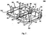
Fig. 7 is a schematic perspective view of a solar cell array. -
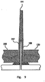
Fig. 8 is a partially sectional view of the solar cell assembly taken along the line 7-7 inFig. 7 , which illustrates the adjacent second portions of the adjacent interconnection members. -
Fig. 9 illustrates a situation where at least the end portions of the two adjacent second portions of the interconnection members as illustrated inFig. 8 are attached with each other. -
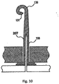
Fig. 10 is a partially sectional view of the solar cell array, in which at least the end portions of the adjacent second portions of the adjacent interconnection members as illustrated inFig. 9 are bended. -
Figs. 11 and12 each illustrate a flow chart of an example of method for manufacturing a solar cell array according to an embodiment of the present disclosure. - Embodiments of the present invention will be described in detail below with reference to the drawings. Note that similar reference numerals refer to similar elements throughout the drawings, and thus repetitive descriptions thereof are omitted.
-
Fig. 1 is a schematic perspective view of an example of asolar cell assembly 300, in whichconductive interconnection members 106 through 109 are attached to asolar cell 100.Fig. 2 illustrates a sectional view taken along the line 2-2 ofFig. 1 .Fig. 3 is a schematic perspective view of an example of thesolar cell 100.Fig. 4 illustrates a sectional view taken along the line 4-4 ofFig. 3 . - According to an example, the
solar cell assembly 300 may include asolar cell 100 and a conductive interconnection member (106, 107, 108, or 109) attached to atop surface 101 of thesolar cell 100, as illustrated inFig. 1 . - The solar cell 100 (hereinafter, also referred as first solar cell) may be cut out from a wafer in which wafer a number (for example, two, or, more or less) of solar cells are manufactured as those skilled in the art would apparently understand. An example of the
solar cell 100 is illustrated InFig. 3 . - In some preferred embodiments, as illustrated in
Fig. 3 , thesolar cell 100 may include four (4)connection parts 102 through 105 (which can be referred as first connection parts hereinafter) formed on the top surface of thesolar cell 100; however, the invention is not limited thereto as long as at least one connection part can be formed on thetop surface 101 of thesolar cell 100. In a preferred embodiment, there may be at least two connection parts formed on the top surface of thesolar cell 100, one(s) for connection to a node of the first solar cell and other one(s) for connection to a cathode of the solar cell. Note that there may also be additional connection part(s) formed on the top surface of the solar cell for connection to/from a bypass circuit which can be formed in or external to the solar cell. - It is be noted that the connection parts 102-105 as shown are just exemplary and not for limiting the scope of the invention. For example, the connection parts 102-105 can be flush with, or recessed from, the
top surface 101, although they are illustrated as being projected from thetop surface 101. As a more specific example, pads formed on the top surface of the solar cell, which can be surrounded by for example a passivation layer, can be used as the connection part. Further, as the connection parts, for example, various terminals formed on the top surface of the solar cell can also be used as appropriate. - Further, it is preferable in some embodiments that the connection part is formed adjacent to an edge of the top surface of the solar cell. As shown in
Fig. 3 , two of theconnection parts edge 110 of thetop surface 101 while other twoconnection parts opposite edge 111 of thetop surface 101. Note that the number and arrangement of the connection parts on the top surface of the solar cell should not be limited to those illustrated in the drawings. - Although the outer edges of the connection parts are illustrated as being aligned with the edge of the top surface of the solar cell in
Fig. 4 , the invention should not be limited thereto. For example, the outer edges of the connection parts may be slightly distanced from the edge of the top surface of the solar cell in an implementation of the embodiment. - The interconnection members 106-109 can be attached to a
top surface 101 of thesolar cell 100 by, for example, welding or soldering. Each of the interconnection members 106-109 includes a first portion and a second portion attached to the first portion with an angle formed therebetween. By way of example, as illustrated inFig. 2 , theinterconnection members first portion 1071/1081 and asecond portion 1072/1082 attached to the first portion with an angle (which is not specifically indicated) formed therebetween. - In a preferred embodiment, the angle formed by the first portion and the second portion of an interconnection member can be in a range from 85 degrees to 90 degrees. In a more preferred embodiment, the first portion is substantially perpendicular to the second portion, as exemplary illustrated in
Fig. 2 . That is, the interconnection member can be of an L-like shape in a sectional view. In some preferred embodiments, the interconnection members can be formed of metal, and for example, it can be a metal plate. As material for forming the interconnection member, molybdenum; a nickel-cobalt ferrous alloy material designed to be compatible with the thermal expansion characteristics of borosilicate glass such as that available under the trade designation Kovar from Carpenter Technology Corporation; a nickel iron alloy material having a uniquely low coefficient of thermal expansion available under the trade designation Invar, FeNi36, or 64FeNi; or the like can be used. - Further, as can be seen from
Figs. 3 and 4 , the first portion and the second portion of the interconnection member can be substantially rectangular in shape. In a preferred embodiment, the interconnection member, including the first and second portions, may have a thickness in a range from about 0.0007 inches and 0.0013 inches (or between about 0.0178mm and 0.033mm). - In some certain embodiments, the interconnection member can be used for, among others, providing electric connection to/from the solar cell. In such a case, the first portions of the interconnection members 106-109 can be attached to respective connection parts 102-105 of the
solar cell 100. In a preferred embodiment, the interconnection member are attached to a respective connection part such that the second portion thereof is closer to the edge, which is adjacent thereto, than the first portion thereof, as illustrated InFigs. 1 and 2 . In another preferred embodiment, the bottom surface of the first portion of the interconnection member (e.g., 106) Is located within the top surface of the respective connection part (e.g., 102) formed on the top surface of thesolar cell 100, that is to say, not out of the circumference of the connection part. In a more specific embodiment, the first portion of the interconnection member (e.g., any of 106 through 109), which is to be attached to the respective connection part formed on the top surface of thesolar cell 100, has a dimension (e.g., width) approximately equal to or less than that of the respective connection part. It needs to be noted that the above embodiments are just for exemplary, and not for limiting the scope of the invention. There is no particular limitation on the shapes of the connection parts or on the deployment of the interconnection members. - As aforementioned, the number and arrangement of the connection parts formed on the top surface of the solar cell are not limited to the case as illustrated in
Figs. 1-2 , accordingly, the number and arrangement of the interconnection members are also not limited to the case as illustrated inFigs. 3-4 . Note that the correspondence between the connection parts and the interconnection members is not limited to a one-to-one manner, for example, there may possibly be such a case where two interconnection members are attached to a same connection part formed on the top surface of the solar cell; and vice versa. - Further, at least an end portion of the second portion is capable of being bended together with at least an end portion of an second portion of an interconnection member of another said solar cell assembly, in an operating state. The interconnection member of another said solar cell assembly can be similar to the interconnection member as above described, and may comprise a first portion and the second portion attached to the first portion with an angle formed therebetween, and the first portion of the another interconnection member is attached to a connection part formed on a top surface of the another solar cell.
-
Fig. 5 is a schematic sectional view of asolar cell assembly 500 according to another embodiment of the invention in which aglass cover 120 is disposed above thetop surface 101 of thesolar cell 100. In an example of the embodiment, theglass cover 120 is disposed above the top surface of thesolar cell 100 to which the interconnection members (e.g. 107 and 108) have been attached. That is, the glass cover is disposed above the top surface of thesolar cell 100 after the interconnection member (e.g. 107) is attached to the solar cell; and the invention should not be limited thereto. It is preferable that the glass cover is transparent for lights. Since the materials for forming the glass cover and method for disposing or attaching the glass cover onto the top surface of the solar cell are not concerns of the invention, the specific descriptions thereof are omitted, and those skilled in the art can take use of the materials and methods known in the art or future developed. - According to the above embodiments of the present disclosure, the density of the solar cells, for example, in a solar cell array can be increased, that is, more solar cells can be mounted in a limited area, which would be advantageous.
-
Fig. 6 is a schematic perspective view of anothersolar cell assembly 600 according to the embodiment of the invention. Thesolar cell assembly 600 according to this embodiment is substantially identical with that as illustrated inFig. 1 , and may comprise: a solar cell 200 (hereinafter, referred as second solar cell), andinterconnection members 206 through 209 each comprising a first portion and a second portion attached to the first portion with an angle formed therebetween, wherein the first portion of the second interconnection member is attached to atop surface 201 of the second solar cell. - In this embodiment, the
solar cell 200 can include connection parts (hereinafter, referred as second connection parts) 202 through 205 formed on thetop surface 201 thereof and adjacent to edges of the top surface, respectively. And, the first portions of the second interconnection members 206-209 are attached to the respective connection parts 202-205 of the second solar cell. - The above descriptions with respect to the solar cell assemblies illustrated in connection with
Figs. 1-5 can also be equivalently applied to the solar cell assembly according to this embodiment, and thus, the repetitive descriptions thereof are omitted. -
Fig. 7 is a schematic perspective view of asolar cell array 700 according to a further embodiment, which comprises at least a first solar cell assembly (e.g., 500) and a second solar cell assembly (e.g., 600), in which the first solar cell and the second solar cell are arranged adjacent to each other. As shown, the firstsolar cell 100 and of the secondsolar cell 200 are arranged adjacent to each other such that second portions of the adjacent interconnection members for the first and second solar cells are adjacent to each other. Thus, thetop surface 101 of the firstsolar cell 100 and thetop surface 201 of the secondsolar cell 200 are arranged adjacent to each other, for example, laterally as illustrated inFig.7 . In an preferred embodiment, theedges - Either or both of glass covers 120 and 220 can be disposed above the respective surface(s) 101 and/or 201 of the solar cell(s), after or prior to the arranging of the
top surfaces -
Fig. 8 is a partially sectional view of the solar cell assembly taken along the line 7-7 inFig. 7 , which illustrates the adjacentsecond portions adjacent interconnection members Fig. 8 , the second portions (e.g., 1082 and 2072) sufficiently extend beyond the corresponding glass cover. However, the present invention is not limited to the embodiment as shown inFig. 8 . In some preferred embodiments, the length of a part of the second portion (e.g., 1082/2072) extending over a top surface of the corresponding glass cover may be in a range about from 0 to 0.1 inches (or, about 2.54 mm). - According to the above embodiments, the solar cells can be disposed or mounted very close to each other, thus the density of the solar cells in a unit area can be increased. Further, according to some certain embodiments, the aspect ratio of the solar cell array can be reduced, in other words, the height of the solar cell assembly and the solar cell array can be reduced. Moreover, the resistance capability against the strain or stress when the array is curled or stretched can be enhanced with use of the interconnection member according to the present disclosure.
- Then, as illustrated in
Fig. 9 , at least end portions of thesecond portions interconnection members solar cell 100 and the respective second connection part 203 (for example, connected to a negative/minus electrode) of the secondsolar cell 200 can be made. By this way, the solar cells can be electrically connected in series or in parallel. -
Fig. 10 is a partially sectional view of the solar cell array, in which at least end portions of the adjacentsecond portions adjacent interconnection members Fig. 9 are bended together with each other. For example, they can be bended so that they can be curled or rolled into a spiral-like shape, as indicated by thereference number 130 inFig. 10 ; and the present disclosure should not be limited thereto. - Because of the bending of the end portions, the aspect ratio of the solar cell array can be further reduced, in other words, the height of the solar cell array can be further reduced. This is particularly advantageous in such a case where the solar cell array needs to be curled or rolled, for example, in the case where the aerospace craft, on which the solar cell array is mounted on its wings, is being launched by a rocket into the space. Further, because of the bending of the end portions, the resistance capability against the strain or stress due to, for example, the curling or stretching of the solar cell array can be further enhanced, thus the reliability of the solar cell array can be improved.
- Moreover, note that the aerospace craft on which the solar cell array is mounted generally is operated in an aerospace environment in which there is no air circumference to block the space particle rays (cosmic rays). In such applications, the
tip 131 of the attached end portions of thesecond portions - In some examples of the embodiment, at least the end portions of the
second portions second portions Figs. 9 and10 . In some alternative examples of the embodiment, at least the end portions of thesecond portions second interconnection members second portions - According to another embodiment, the solar cell array may further comprise a carrier (not shown), wherein the solar cell(s), e.g., 100 and/or 200) can be mounted on the carrier by for example, silicone adhesive, with bottom surfaces thereof facing the carrier. In an embodiment, the carrier can be formed of aluminium or titanium. In a preferred embodiment, the carrier is capable of being bended and stretched.
- Accordingly, methods for manufacturing the solar cell array are also provided. Hereinafter, a method for manufacturing the solar cell array according to embodiments of the present disclosure will be described with reference to
Figs. 11 and12 . -
Figs. 11 and12 each illustrate a flow chart of an example of method for manufacturing a solar cell array according to an embodiment of the present disclosure. - A method for manufacturing a solar cell array according to an embodiment of the present disclosure may comprises: providing (S1101) a first solar cell assembly, the first solar cell assembly comprising a first solar cell and a first interconnection member, the first interconnection member comprising a first portion and a second portion attached to the first portion with an angle formed therebetween, wherein the first portion is attached to a top surface of the first solar cell; providing (S1103) a second solar cell assembly, the second solar cell assembly comprising a second solar cell and a second interconnection member, the second interconnection member comprising a first portion and a second portion attached to the first portion with an angle formed therebetween, wherein the first portion of the second interconnection member is attached to a top surface of the second solar cell; arranging (S1105) the first solar cell and the second solar cell adjacent to each other such that the second portion of the first interconnect member and the second portion of the second interconnection member are adjacent to each other; and bending (S1107) at least the end portion of the second portion of the first interconnection member together with at least the end portion of the second portion of the second interconnection member.
- A method for manufacturing a solar cell array according to another embodiment of the present disclosure may comprises: providing (S1201) a first solar cell; attaching (S1203) a first interconnection member to the first solar cell with a first portion of the interconnection member attached to a top surface of the solar cell, the interconnection member comprising the first portion and a second portion attached to the first portion with an angle formed therebetween; providing (S1205) a second solar cell; attaching (S1207) a second interconnection member to the second solar cell with a first portion of the second interconnection member attached to a top surface of the second solar cell, the second interconnection member comprising the first portion and a second portion attached to the first portion with an angle formed therebetween; arranging (S1209) the first solar cell and the second solar cell adjacent to each other such that the second portion of the first interconnect member and the second portion of the second interconnection member are adjacent to each other and bending (S1211) at least the end portion of the second portion of the first interconnection member together with at least the end portion of the second portion of the second interconnection member.
- In an implementation of the embodiment, the methods may further comprise: attaching at least the end portions of the second portions of the first and second interconnect members are attached to each other prior to said bending. In another implementation of the embodiment, the first and second interconnection members are formed integrally with at least the end portions of the second portions thereof attached to each other.
- In an implementation of the embodiment, said bending causes at least the end portions of the second portions of the first and second interconnection member to be curled into a spiral-like shape.
- In an implementation of the embodiment, at least one of the first and second interconnection members is a metal plate with L-like shape.
- In an implementation of the embodiment, at least one of the first and second interconnection members is formed of molybdenum; a nickel-cobalt ferrous alloy material designed to be compatible with the thermal expansion characteristics of borosilicate glass such as that available under the trade designation Kovar from Carpenter Technology Corporation; or a nickel iron alloy material having a uniquely low coefficient of thermal expansion available under the trade designation Invar, FeNi36, or 64FeNi.
- In an implementation of the embodiment, the first and second portions of at least one of the first and second interconnection members are substantially rectangular in shape, with a thickness in a range from about 0.0007 inches to about 0.0013 inches.
- In an implementation of the embodiment, the methods may further comprise: disposing a glass cover above the top surface of any one of the first and second solar cells after the corresponding interconnection member is attached to any one of the first and second solar cells.
- In an implementation of the embodiment, length of a part of the second portion of said any one of the first and second solar cells extending over a top surface of the glass cover is in a range from 0 to about 0.1 inches.
- In an implementation of the embodiment, each of the first and second solar cells further comprise a connection part formed on a top surface thereof and adjacent to an edge of the top surface, and wherein the first portions of the first and second interconnection members are attached to the respective connection parts of the first and second solar cell.
- In an implementation of the embodiment, said attaching of any of the first and second interconnection members is carried out by any of: welding or soldering.
- In an implementation of the embodiment, said arranging causes that a maximum distance between the respective edges of the first and second solar cells adjacent to the first and second interconnection members is 0.15 inches or less.
- In an implementation of the embodiment, the first solar cell includes at least two said first connection parts, one of the first connection parts for connection to a node of the first solar cell and another one of the first connection parts for connection to a cathode of the first solar cell.
- In an implementation of the embodiment, said attaching of a first interconnection member comprises: attaching at least two said first interconnection members to the respective first connection parts of the first solar cell.
- In an implementation of the embodiment, said attaching of at least one of the first and second interconnection members causes that the second portion of said at least one of the first and second interconnection members is closer to the corresponding edge, which is adjacent thereto, than the first portion thereof.
- In an implementation of the embodiment, the method may further comprise mounting the first and second solar cells onto the carrier with bottom surfaces of the first and second solar cells facing the carrier. Said mounting step can be performed after or before the interconnection member(s) for the first and/or the second solar cell is attached to the respective solar cell(s), depending on different implementations of the embodiment.
- Note that the embodiments of the present disclosure can be freely combined with each other without departing from the spirit and scope of the invention.
- It is possible to embody the solar cell assemblies, solar cell arrays, and the methods for manufacturing the same of the present disclosure in various ways. The above described orders of the steps for the methods are only intended to be illustrative, and the steps of the methods of the present disclosure are not limited to the above specifically described orders unless otherwise specifically stated.
- Although some specific embodiments of the present invention have been demonstrated in detail with examples, it should be understood by a person skilled in the art that the above examples are only intended to be illustrative but not to limit the scope of the present invention. It should be understood that the above embodiments can be modified without departing from the scope of the present invention which is to be defined by the attached claims.
Claims (7)
- A method for fabricating a solar cell array (300) comprising:providing a first solar cell (100) having a first terminal (104) disposed on one side of the first solar cell (100) adjacent a first edge (111) of the first solar cell (100), and a second terminal (103) disposed on said one side of the first solar cell (100) adjacent a second edge of the first solar cell (100) opposite to the first edge (111);providing a second solar cell (200) having a first terminal (203) disposed on one side of the second solar cell (200) adjacent a first edge (211) of the second solar cell (200), and a second terminal disposed on said one side of the second solar cell (200) adjacent a second edge of the second solar cell opposite to the first edge (211) of the second solar cell (200);providing a first metal interconnection member (106-109) having a L-shape, with a bottom first portion having a width approximately equal to or less than the width of the first terminal (104) of the first solar cell (100), and a second portion attached to said first portion of the first metal interconnection member (106-109) and extending perpendicular thereto;securely attaching the bottom first portion of the first metal interconnection member (106-109) to the first terminal (104) of the first solar cell (100);providing a second metal interconnection member (206-209) having a L-shape, with a bottom first portion having a width approximately equal to or less than the width of the second terminal of the second solar cell (200), and a second portion attached to said bottom first portion of the second metal interconnection member (206-209) and extending perpendicular thereto;securely attaching the bottom first portion of the second metal interconnection member (206-209) to the second terminal of the second solar cell (200);aligning the first edge (111) of the first solar cell with the second edge (210) of the second solar cell (200) so that the two edges are substantially parallel and uniformly spaced apart by no less than 0.0254 cm (0.01 inches) and no greater than 0.0381 cm (0.15 inches), and the second portion of the first metal interconnection member (106-109) is adjacent the second portion of the second metal interconnection member (206-209); andsecurely attaching the second portion of the first metal interconnection member (106-109) to the second portion of the second metal interconnection member (206-209) so that an electrically conductive interconnection is made between the first terminal (104) of the first solar cell (100) to the second terminal of the second solar cell (200).
- A method for fabricating a solar cell array as defined in claim 1, further comprising attaching a cover glass over the top surface of the first solar cell, and/or wherein the cover glass is attached to the first solar cell after the first metal interconnection member is attached to the first solar cell.
- A method for fabricating a solar cell array as defined in claim 1, further comprising mounting the bottom side of the first and second solar cells on a carrier.
- A method for fabricating a solar cell array as defined in claim 3, wherein the mounting on the carrier utilizes a silicone adhesive, and/or wherein the carrier is composed of aluminium or titanium.
- A method for fabricating a solar cell array as defined in claim 1, further comprising bending the end portion of the attached second portions of the first and second interconnection members so that the end portion is rolled into a spiral.
- A method for fabricating a solar cell array as defined in claim 2, wherein the height of the second portion of the first interconnection member over the top surface of the cover glass may range between 0.0 and 0.0254 cm (0.1 inch).
- A method for fabricating a solar cell array as defined in claim 1, wherein the first terminal corresponds to an anode terminal of the solar cell, and the second terminal corresponds to a cathode terminal of the solar cell.
Applications Claiming Priority (1)
| Application Number | Priority Date | Filing Date | Title |
|---|---|---|---|
| US13/535,570 US9102422B2 (en) | 2012-06-28 | 2012-06-28 | Solar cell assembly, solar cell panel, and method for manufacturing the same |
Publications (2)
| Publication Number | Publication Date |
|---|---|
| EP2680319A1 EP2680319A1 (en) | 2014-01-01 |
| EP2680319B1 true EP2680319B1 (en) | 2019-09-11 |
Family
ID=48470705
Family Applications (1)
| Application Number | Title | Priority Date | Filing Date |
|---|---|---|---|
| EP13020021.5A Active EP2680319B1 (en) | 2012-06-28 | 2013-05-22 | Method for manufacturing a solar cell array |
Country Status (3)
| Country | Link |
|---|---|
| US (2) | US9102422B2 (en) |
| EP (1) | EP2680319B1 (en) |
| DE (1) | DE102013008287A1 (en) |
Families Citing this family (8)
| Publication number | Priority date | Publication date | Assignee | Title |
|---|---|---|---|---|
| US9634172B1 (en) | 2007-09-24 | 2017-04-25 | Solaero Technologies Corp. | Inverted metamorphic multijunction solar cell with multiple metamorphic layers |
| US10381501B2 (en) | 2006-06-02 | 2019-08-13 | Solaero Technologies Corp. | Inverted metamorphic multijunction solar cell with multiple metamorphic layers |
| US9117966B2 (en) | 2007-09-24 | 2015-08-25 | Solaero Technologies Corp. | Inverted metamorphic multijunction solar cell with two metamorphic layers and homojunction top cell |
| US10381505B2 (en) | 2007-09-24 | 2019-08-13 | Solaero Technologies Corp. | Inverted metamorphic multijunction solar cells including metamorphic layers |
| US9102422B2 (en) | 2012-06-28 | 2015-08-11 | Solaero Technologies Corp. | Solar cell assembly, solar cell panel, and method for manufacturing the same |
| TWI628909B (en) | 2016-12-21 | 2018-07-01 | 財團法人工業技術研究院 | Expandable photovoltaic submodules |
| USD845889S1 (en) | 2018-01-16 | 2019-04-16 | Solaero Technologies Corp. | Flexible interconnecting member for solar cells |
| US10529881B2 (en) | 2018-03-01 | 2020-01-07 | Solaero Technologies Corp. | Interconnect member |
Citations (4)
| Publication number | Priority date | Publication date | Assignee | Title |
|---|---|---|---|---|
| GB1328324A (en) * | 1971-03-19 | 1973-08-30 | Licentia Gmbh | Solar cell and method of producing solar cells |
| US5180442A (en) * | 1992-04-06 | 1993-01-19 | Eric Elias | Integration system for solar modules |
| US7419377B1 (en) * | 2007-08-20 | 2008-09-02 | Solaria Corporation | Electrical coupling device and method for solar cells |
| JP2008227085A (en) * | 2007-03-12 | 2008-09-25 | Sharp Corp | Solar cell array, solar cell module, and manufacturing method of solar cell array |
Family Cites Families (19)
| Publication number | Priority date | Publication date | Assignee | Title |
|---|---|---|---|---|
| US3375141A (en) | 1963-07-22 | 1968-03-26 | Aiken Ind Inc | Solar cell array |
| US5180689A (en) * | 1991-09-10 | 1993-01-19 | Taiwan Semiconductor Manufacturing Company | Tapered opening sidewall with multi-step etching process |
| DE19836272C2 (en) | 1998-08-11 | 2003-08-07 | Astrium Gmbh | Flexible, foldable solar generator for spacecraft |
| US6555739B2 (en) * | 2001-09-10 | 2003-04-29 | Ekla-Tek, Llc | Photovoltaic array and method of manufacturing same |
| JP3932029B2 (en) | 2002-04-22 | 2007-06-20 | 富士電機ホールディングス株式会社 | Installation method of solar cell module |
| US7423346B2 (en) * | 2004-09-09 | 2008-09-09 | Megica Corporation | Post passivation interconnection process and structures |
| DE102004044061A1 (en) | 2004-09-11 | 2006-04-20 | Rwe Space Solar Power Gmbh | Solar cell arrangement and method for interconnecting a solar cell string |
| CN2818628Y (en) | 2005-07-20 | 2006-09-20 | 常州天合光能有限公司 | Universal photovoltaic building constructional member |
| US7732705B2 (en) | 2005-10-11 | 2010-06-08 | Emcore Solar Power, Inc. | Reliable interconnection of solar cells including integral bypass diode |
| US7498508B2 (en) | 2006-02-24 | 2009-03-03 | Day4 Energy, Inc. | High voltage solar cell and solar cell module |
| US20100186804A1 (en) | 2009-01-29 | 2010-07-29 | Emcore Solar Power, Inc. | String Interconnection of Inverted Metamorphic Multijunction Solar Cells on Flexible Perforated Carriers |
| EP2132782B1 (en) | 2007-02-15 | 2012-07-11 | Transform Solar Pty Ltd. | A substrate assembly, an assembly process, and an assembly apparatus |
| CN201038172Y (en) | 2007-04-29 | 2008-03-19 | 厦门冠宇科技有限公司 | Flexible solar cell assembly connection style |
| CN101483201A (en) | 2008-02-26 | 2009-07-15 | 苏州斯派特光电技术有限公司 | Direct connecting type thin-film solar cell module and manufacturing method thereof |
| US8263853B2 (en) | 2008-08-07 | 2012-09-11 | Emcore Solar Power, Inc. | Wafer level interconnection of inverted metamorphic multijunction solar cells |
| US7960201B2 (en) | 2009-01-29 | 2011-06-14 | Emcore Solar Power, Inc. | String interconnection and fabrication of inverted metamorphic multijunction solar cells |
| CN101853891B (en) | 2009-04-02 | 2013-09-04 | 沙晓林 | Thin-film solar panel array |
| US20100282288A1 (en) | 2009-05-06 | 2010-11-11 | Emcore Solar Power, Inc. | Solar Cell Interconnection on a Flexible Substrate |
| US9102422B2 (en) | 2012-06-28 | 2015-08-11 | Solaero Technologies Corp. | Solar cell assembly, solar cell panel, and method for manufacturing the same |
-
2012
- 2012-06-28 US US13/535,570 patent/US9102422B2/en active Active
-
2013
- 2013-05-15 DE DE102013008287.0A patent/DE102013008287A1/en active Pending
- 2013-05-22 EP EP13020021.5A patent/EP2680319B1/en active Active
-
2015
- 2015-07-07 US US14/793,289 patent/US9153721B1/en active Active
Patent Citations (4)
| Publication number | Priority date | Publication date | Assignee | Title |
|---|---|---|---|---|
| GB1328324A (en) * | 1971-03-19 | 1973-08-30 | Licentia Gmbh | Solar cell and method of producing solar cells |
| US5180442A (en) * | 1992-04-06 | 1993-01-19 | Eric Elias | Integration system for solar modules |
| JP2008227085A (en) * | 2007-03-12 | 2008-09-25 | Sharp Corp | Solar cell array, solar cell module, and manufacturing method of solar cell array |
| US7419377B1 (en) * | 2007-08-20 | 2008-09-02 | Solaria Corporation | Electrical coupling device and method for solar cells |
Also Published As
| Publication number | Publication date |
|---|---|
| EP2680319A1 (en) | 2014-01-01 |
| US20150311372A1 (en) | 2015-10-29 |
| US9153721B1 (en) | 2015-10-06 |
| US9102422B2 (en) | 2015-08-11 |
| DE102013008287A1 (en) | 2014-01-02 |
| US20140000672A1 (en) | 2014-01-02 |
Similar Documents
| Publication | Publication Date | Title |
|---|---|---|
| EP2680319B1 (en) | Method for manufacturing a solar cell array | |
| CN107078174B (en) | Solar battery interconnection piece | |
| CN109496366B (en) | Battery-to-battery interconnects | |
| US9627565B2 (en) | Integral corner bypass diode interconnecting configuration for multiple solar cells | |
| CN109273803A (en) | Secondary battery module | |
| US9735300B2 (en) | Thermal management | |
| US11545589B2 (en) | Single cell photovoltaic module | |
| EP2767840A1 (en) | Measurement jig for solar battery and method for measuring output of solar battery cell | |
| EP2894676B1 (en) | Solar cell array having two different types of cells | |
| US9412891B2 (en) | Thermal receiver for high power solar concentrators and method of assembly | |
| US20190355959A1 (en) | Battery module | |
| CN110337738A (en) | The manufacturing method of separator, battery module and battery module | |
| CN109390518A (en) | Battery unit frame, battery module and battery pack and vehicle including battery module | |
| JP6640080B2 (en) | Connection arrangement for connecting at least one voltage source and / or voltage sink in the form of a cell to an external electrical component, and an electrical arrangement comprising the connection arrangement | |
| EP3032614B1 (en) | Battery module and battery cell | |
| US20160190527A1 (en) | Battery module and manufacturing method thereof | |
| US9577131B2 (en) | Concentrator photovoltaic module, concentrator photovoltaic panel, and flexible printed circuit for concentrator photovoltaic module | |
| US20200194765A1 (en) | Secondary battery | |
| EP3401979A1 (en) | Battery structure and laminated battery | |
| CN202855777U (en) | Solar module and solar energy battery panel | |
| US10930835B2 (en) | Thermoelectric module sheet and thermoelectric module assembly including the same | |
| EP3428981B1 (en) | Thermoelectric conversion module | |
| TW201637249A (en) | Thermoelectric generator | |
| CN103633167B (en) | Solar cell module, solar battery panel and its manufacture method | |
| EP3220423B1 (en) | Solar cell stack structure having no gap between solar cell and substrate |
Legal Events
| Date | Code | Title | Description |
|---|---|---|---|
| PUAI | Public reference made under article 153(3) epc to a published international application that has entered the european phase |
Free format text: ORIGINAL CODE: 0009012 |
|
| AK | Designated contracting states |
Kind code of ref document: A1 Designated state(s): AL AT BE BG CH CY CZ DE DK EE ES FI FR GB GR HR HU IE IS IT LI LT LU LV MC MK MT NL NO PL PT RO RS SE SI SK SM TR |
|
| AX | Request for extension of the european patent |
Extension state: BA ME |
|
| 17P | Request for examination filed |
Effective date: 20140701 |
|
| RBV | Designated contracting states (corrected) |
Designated state(s): AL AT BE BG CH CY CZ DE DK EE ES FI FR GB GR HR HU IE IS IT LI LT LU LV MC MK MT NL NO PL PT RO RS SE SI SK SM TR |
|
| RAP1 | Party data changed (applicant data changed or rights of an application transferred) |
Owner name: SOLAERO TECHNOLOGIES CORP. |
|
| STAA | Information on the status of an ep patent application or granted ep patent |
Free format text: STATUS: EXAMINATION IS IN PROGRESS |
|
| 17Q | First examination report despatched |
Effective date: 20161209 |
|
| REG | Reference to a national code |
Ref country code: DE Ref legal event code: R079 Ref document number: 602013060251 Country of ref document: DE Free format text: PREVIOUS MAIN CLASS: H01L0031045000 Ipc: H01L0031050000 |
|
| GRAP | Despatch of communication of intention to grant a patent |
Free format text: ORIGINAL CODE: EPIDOSNIGR1 |
|
| STAA | Information on the status of an ep patent application or granted ep patent |
Free format text: STATUS: GRANT OF PATENT IS INTENDED |
|
| RIC1 | Information provided on ipc code assigned before grant |
Ipc: H02S 30/20 20140101ALI20190228BHEP Ipc: H01L 31/048 20140101ALI20190228BHEP Ipc: B64G 1/54 20060101ALI20190228BHEP Ipc: B64G 1/44 20060101ALI20190228BHEP Ipc: H01L 31/041 20140101ALI20190228BHEP Ipc: H01L 31/05 20140101AFI20190228BHEP |
|
| INTG | Intention to grant announced |
Effective date: 20190327 |
|
| GRAS | Grant fee paid |
Free format text: ORIGINAL CODE: EPIDOSNIGR3 |
|
| GRAA | (expected) grant |
Free format text: ORIGINAL CODE: 0009210 |
|
| STAA | Information on the status of an ep patent application or granted ep patent |
Free format text: STATUS: THE PATENT HAS BEEN GRANTED |
|
| AK | Designated contracting states |
Kind code of ref document: B1 Designated state(s): AL AT BE BG CH CY CZ DE DK EE ES FI FR GB GR HR HU IE IS IT LI LT LU LV MC MK MT NL NO PL PT RO RS SE SI SK SM TR |
|
| REG | Reference to a national code |
Ref country code: GB Ref legal event code: FG4D |
|
| REG | Reference to a national code |
Ref country code: CH Ref legal event code: EP |
|
| REG | Reference to a national code |
Ref country code: AT Ref legal event code: REF Ref document number: 1179600 Country of ref document: AT Kind code of ref document: T Effective date: 20190915 |
|
| REG | Reference to a national code |
Ref country code: DE Ref legal event code: R096 Ref document number: 602013060251 Country of ref document: DE |
|
| REG | Reference to a national code |
Ref country code: IE Ref legal event code: FG4D |
|
| REG | Reference to a national code |
Ref country code: NL Ref legal event code: FP |
|
| REG | Reference to a national code |
Ref country code: LT Ref legal event code: MG4D |
|
| PG25 | Lapsed in a contracting state [announced via postgrant information from national office to epo] |
Ref country code: LT Free format text: LAPSE BECAUSE OF FAILURE TO SUBMIT A TRANSLATION OF THE DESCRIPTION OR TO PAY THE FEE WITHIN THE PRESCRIBED TIME-LIMIT Effective date: 20190911 Ref country code: HR Free format text: LAPSE BECAUSE OF FAILURE TO SUBMIT A TRANSLATION OF THE DESCRIPTION OR TO PAY THE FEE WITHIN THE PRESCRIBED TIME-LIMIT Effective date: 20190911 Ref country code: FI Free format text: LAPSE BECAUSE OF FAILURE TO SUBMIT A TRANSLATION OF THE DESCRIPTION OR TO PAY THE FEE WITHIN THE PRESCRIBED TIME-LIMIT Effective date: 20190911 Ref country code: NO Free format text: LAPSE BECAUSE OF FAILURE TO SUBMIT A TRANSLATION OF THE DESCRIPTION OR TO PAY THE FEE WITHIN THE PRESCRIBED TIME-LIMIT Effective date: 20191211 Ref country code: BG Free format text: LAPSE BECAUSE OF FAILURE TO SUBMIT A TRANSLATION OF THE DESCRIPTION OR TO PAY THE FEE WITHIN THE PRESCRIBED TIME-LIMIT Effective date: 20191211 Ref country code: SE Free format text: LAPSE BECAUSE OF FAILURE TO SUBMIT A TRANSLATION OF THE DESCRIPTION OR TO PAY THE FEE WITHIN THE PRESCRIBED TIME-LIMIT Effective date: 20190911 |
|
| PG25 | Lapsed in a contracting state [announced via postgrant information from national office to epo] |
Ref country code: RS Free format text: LAPSE BECAUSE OF FAILURE TO SUBMIT A TRANSLATION OF THE DESCRIPTION OR TO PAY THE FEE WITHIN THE PRESCRIBED TIME-LIMIT Effective date: 20190911 Ref country code: GR Free format text: LAPSE BECAUSE OF FAILURE TO SUBMIT A TRANSLATION OF THE DESCRIPTION OR TO PAY THE FEE WITHIN THE PRESCRIBED TIME-LIMIT Effective date: 20191212 Ref country code: AL Free format text: LAPSE BECAUSE OF FAILURE TO SUBMIT A TRANSLATION OF THE DESCRIPTION OR TO PAY THE FEE WITHIN THE PRESCRIBED TIME-LIMIT Effective date: 20190911 Ref country code: LV Free format text: LAPSE BECAUSE OF FAILURE TO SUBMIT A TRANSLATION OF THE DESCRIPTION OR TO PAY THE FEE WITHIN THE PRESCRIBED TIME-LIMIT Effective date: 20190911 Ref country code: ES Free format text: LAPSE BECAUSE OF FAILURE TO SUBMIT A TRANSLATION OF THE DESCRIPTION OR TO PAY THE FEE WITHIN THE PRESCRIBED TIME-LIMIT Effective date: 20190911 |
|
| REG | Reference to a national code |
Ref country code: AT Ref legal event code: MK05 Ref document number: 1179600 Country of ref document: AT Kind code of ref document: T Effective date: 20190911 |
|
| PG25 | Lapsed in a contracting state [announced via postgrant information from national office to epo] |
Ref country code: AT Free format text: LAPSE BECAUSE OF FAILURE TO SUBMIT A TRANSLATION OF THE DESCRIPTION OR TO PAY THE FEE WITHIN THE PRESCRIBED TIME-LIMIT Effective date: 20190911 Ref country code: PL Free format text: LAPSE BECAUSE OF FAILURE TO SUBMIT A TRANSLATION OF THE DESCRIPTION OR TO PAY THE FEE WITHIN THE PRESCRIBED TIME-LIMIT Effective date: 20190911 Ref country code: EE Free format text: LAPSE BECAUSE OF FAILURE TO SUBMIT A TRANSLATION OF THE DESCRIPTION OR TO PAY THE FEE WITHIN THE PRESCRIBED TIME-LIMIT Effective date: 20190911 Ref country code: RO Free format text: LAPSE BECAUSE OF FAILURE TO SUBMIT A TRANSLATION OF THE DESCRIPTION OR TO PAY THE FEE WITHIN THE PRESCRIBED TIME-LIMIT Effective date: 20190911 Ref country code: PT Free format text: LAPSE BECAUSE OF FAILURE TO SUBMIT A TRANSLATION OF THE DESCRIPTION OR TO PAY THE FEE WITHIN THE PRESCRIBED TIME-LIMIT Effective date: 20200113 |
|
| PG25 | Lapsed in a contracting state [announced via postgrant information from national office to epo] |
Ref country code: SM Free format text: LAPSE BECAUSE OF FAILURE TO SUBMIT A TRANSLATION OF THE DESCRIPTION OR TO PAY THE FEE WITHIN THE PRESCRIBED TIME-LIMIT Effective date: 20190911 Ref country code: SK Free format text: LAPSE BECAUSE OF FAILURE TO SUBMIT A TRANSLATION OF THE DESCRIPTION OR TO PAY THE FEE WITHIN THE PRESCRIBED TIME-LIMIT Effective date: 20190911 Ref country code: IS Free format text: LAPSE BECAUSE OF FAILURE TO SUBMIT A TRANSLATION OF THE DESCRIPTION OR TO PAY THE FEE WITHIN THE PRESCRIBED TIME-LIMIT Effective date: 20200224 Ref country code: CZ Free format text: LAPSE BECAUSE OF FAILURE TO SUBMIT A TRANSLATION OF THE DESCRIPTION OR TO PAY THE FEE WITHIN THE PRESCRIBED TIME-LIMIT Effective date: 20190911 |
|
| REG | Reference to a national code |
Ref country code: DE Ref legal event code: R097 Ref document number: 602013060251 Country of ref document: DE |
|
| PLBE | No opposition filed within time limit |
Free format text: ORIGINAL CODE: 0009261 |
|
| STAA | Information on the status of an ep patent application or granted ep patent |
Free format text: STATUS: NO OPPOSITION FILED WITHIN TIME LIMIT |
|
| PG2D | Information on lapse in contracting state deleted |
Ref country code: IS |
|
| PG25 | Lapsed in a contracting state [announced via postgrant information from national office to epo] |
Ref country code: DK Free format text: LAPSE BECAUSE OF FAILURE TO SUBMIT A TRANSLATION OF THE DESCRIPTION OR TO PAY THE FEE WITHIN THE PRESCRIBED TIME-LIMIT Effective date: 20190911 Ref country code: IS Free format text: LAPSE BECAUSE OF FAILURE TO SUBMIT A TRANSLATION OF THE DESCRIPTION OR TO PAY THE FEE WITHIN THE PRESCRIBED TIME-LIMIT Effective date: 20200112 |
|
| 26N | No opposition filed |
Effective date: 20200615 |
|
| PG25 | Lapsed in a contracting state [announced via postgrant information from national office to epo] |
Ref country code: SI Free format text: LAPSE BECAUSE OF FAILURE TO SUBMIT A TRANSLATION OF THE DESCRIPTION OR TO PAY THE FEE WITHIN THE PRESCRIBED TIME-LIMIT Effective date: 20190911 |
|
| REG | Reference to a national code |
Ref country code: DE Ref legal event code: R082 Ref document number: 602013060251 Country of ref document: DE Representative=s name: ADARES PATENT- UND RECHTSANWAELTE REININGER & , DE |
|
| PG25 | Lapsed in a contracting state [announced via postgrant information from national office to epo] |
Ref country code: MC Free format text: LAPSE BECAUSE OF FAILURE TO SUBMIT A TRANSLATION OF THE DESCRIPTION OR TO PAY THE FEE WITHIN THE PRESCRIBED TIME-LIMIT Effective date: 20190911 Ref country code: CH Free format text: LAPSE BECAUSE OF NON-PAYMENT OF DUE FEES Effective date: 20200531 Ref country code: LI Free format text: LAPSE BECAUSE OF NON-PAYMENT OF DUE FEES Effective date: 20200531 |
|
| PG25 | Lapsed in a contracting state [announced via postgrant information from national office to epo] |
Ref country code: LU Free format text: LAPSE BECAUSE OF NON-PAYMENT OF DUE FEES Effective date: 20200522 |
|
| PG25 | Lapsed in a contracting state [announced via postgrant information from national office to epo] |
Ref country code: IE Free format text: LAPSE BECAUSE OF NON-PAYMENT OF DUE FEES Effective date: 20200522 |
|
| PG25 | Lapsed in a contracting state [announced via postgrant information from national office to epo] |
Ref country code: TR Free format text: LAPSE BECAUSE OF FAILURE TO SUBMIT A TRANSLATION OF THE DESCRIPTION OR TO PAY THE FEE WITHIN THE PRESCRIBED TIME-LIMIT Effective date: 20190911 Ref country code: MT Free format text: LAPSE BECAUSE OF FAILURE TO SUBMIT A TRANSLATION OF THE DESCRIPTION OR TO PAY THE FEE WITHIN THE PRESCRIBED TIME-LIMIT Effective date: 20190911 Ref country code: CY Free format text: LAPSE BECAUSE OF FAILURE TO SUBMIT A TRANSLATION OF THE DESCRIPTION OR TO PAY THE FEE WITHIN THE PRESCRIBED TIME-LIMIT Effective date: 20190911 |
|
| PG25 | Lapsed in a contracting state [announced via postgrant information from national office to epo] |
Ref country code: MK Free format text: LAPSE BECAUSE OF FAILURE TO SUBMIT A TRANSLATION OF THE DESCRIPTION OR TO PAY THE FEE WITHIN THE PRESCRIBED TIME-LIMIT Effective date: 20190911 |
|
| PGFP | Annual fee paid to national office [announced via postgrant information from national office to epo] |
Ref country code: NL Payment date: 20220420 Year of fee payment: 10 |
|
| PGFP | Annual fee paid to national office [announced via postgrant information from national office to epo] |
Ref country code: IT Payment date: 20220412 Year of fee payment: 10 Ref country code: GB Payment date: 20220401 Year of fee payment: 10 Ref country code: FR Payment date: 20220408 Year of fee payment: 10 Ref country code: DE Payment date: 20220329 Year of fee payment: 10 |
|
| PGFP | Annual fee paid to national office [announced via postgrant information from national office to epo] |
Ref country code: BE Payment date: 20220420 Year of fee payment: 10 |
|
| REG | Reference to a national code |
Ref country code: DE Ref legal event code: R119 Ref document number: 602013060251 Country of ref document: DE |
|
| REG | Reference to a national code |
Ref country code: NL Ref legal event code: MM Effective date: 20230601 |
|
| GBPC | Gb: european patent ceased through non-payment of renewal fee |
Effective date: 20230522 |
|
| REG | Reference to a national code |
Ref country code: BE Ref legal event code: MM Effective date: 20230531 |
|
| PG25 | Lapsed in a contracting state [announced via postgrant information from national office to epo] |
Ref country code: NL Free format text: LAPSE BECAUSE OF NON-PAYMENT OF DUE FEES Effective date: 20230601 |