EP3336874A1 - Interrupteur - Google Patents
Interrupteur Download PDFInfo
- Publication number
- EP3336874A1 EP3336874A1 EP17206303.4A EP17206303A EP3336874A1 EP 3336874 A1 EP3336874 A1 EP 3336874A1 EP 17206303 A EP17206303 A EP 17206303A EP 3336874 A1 EP3336874 A1 EP 3336874A1
- Authority
- EP
- European Patent Office
- Prior art keywords
- switch
- contact
- state
- bench
- electrical
- Prior art date
- Legal status (The legal status is an assumption and is not a legal conclusion. Google has not performed a legal analysis and makes no representation as to the accuracy of the status listed.)
- Granted
Links
Images
Classifications
-
- H—ELECTRICITY
- H01—ELECTRIC ELEMENTS
- H01H—ELECTRIC SWITCHES; RELAYS; SELECTORS; EMERGENCY PROTECTIVE DEVICES
- H01H71/00—Details of the protective switches or relays covered by groups H01H73/00 - H01H83/00
- H01H71/10—Operating or release mechanisms
- H01H71/12—Automatic release mechanisms with or without manual release
- H01H71/46—Automatic release mechanisms with or without manual release having means for operating auxiliary contacts additional to the main contacts
- H01H71/465—Self-contained, easily replaceable microswitches
-
- H—ELECTRICITY
- H01—ELECTRIC ELEMENTS
- H01H—ELECTRIC SWITCHES; RELAYS; SELECTORS; EMERGENCY PROTECTIVE DEVICES
- H01H83/00—Protective switches, e.g. circuit-breaking switches, or protective relays operated by abnormal electrical conditions otherwise than solely by excess current
- H01H83/14—Protective switches, e.g. circuit-breaking switches, or protective relays operated by abnormal electrical conditions otherwise than solely by excess current operated by imbalance of two or more currents or voltages, e.g. for differential protection
Definitions
- the present invention relates to a switch comprising an electrical contact bank arranged to switch between a first contact state where an electric current can flow through the electrical contact bench and a second contact state where the flow of electric current through the bench electrical contact is interrupted.
- Such a switch is generally known.
- This switch acts as a security tool in the electrical network of a building.
- This switch can be operated manually, for example to cut the electrical power when it is necessary to carry out work on the network and thus avoid being electrocuted.
- the switch can also be activated mechanically and automatically in case of overcurrent, short-circuit, or leakage current on the network.
- the invention aims to provide a switch that provides information to a data bus without having to directly intervene on the operation of the switch.
- a switch according to the invention is characterized in that it comprises another switch which is distinct from the electrical contact bench, which other switch is in connection with the electrical contact bench so as to be actuated by a tilting from the contact bank of the first contact state to the second contact state, which other switch has an output and is arranged to provide said output an electrical signal indicating the state of contact of the other switch.
- another switch which is separate from the electrical contact bench, makes it possible not to have to intervene directly on the electrical contact bench and thus considerably limit the risks of interfering with the operation of the switch.
- the other switch Since the other switch is in connection with the electrical contact bank so as to be actuated by a tilting of the contact bank of the first state of contact to the second state of contact, allows the other switch to follow a tilting of the 'light switch.
- the fact of providing an electrical signal indicating a state of contact of the other switch makes it possible to communicate this state of contact, which corresponds to that of the switch, to a bus.
- a first preferred embodiment of a switch according to the invention is characterized in that the electrical contact bench is housed in a housing having an outer wall, which connection between the electrical contact bench and the other switch is formed by a transmission member which is mounted between the outer wall and the other switch, which transmission member is mounted to be moved by a tilting of the contact bale from the first contact state to the second contact state to thereby actuate the other switch.
- the use of a transmission member connecting the housing of the electrical contact bank and the other switch allows a transmission that does not disrupt the operation of the switch.
- a second preferred embodiment of a switch according to the invention is characterized in that the transmission member is formed by a cam.
- a cam forms a reliable and inexpensive transmission.
- a third preferred embodiment of a switch according to the invention is characterized in that it comprises a lug protruding from the outer wall of the housing, which lug is mounted so as to follow the tilting of the contact bench, which transmission member is in contact with said pin.
- the ergot thus forms a transmission piece for transmitting the tilting of the contact bank to the cam.
- a fourth preferred embodiment of a switch according to the invention is characterized in that the other switch is provided with a control pallet placed on an external face of the other switch, the transmission member being in contact with each other. with the control pallet.
- the use of a control pallet allows a reliable interface between the transmission member and the other switch.
- the switch may comprise another housing inside which the transmission member and the other switch are housed.
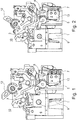
- the switch 10 illustrated in Figures 1 and 2 comprises an electrical contact bench 1 arranged to switch between a first state of contact, as illustrated in FIG. figure 1 , where an electric current can flow through the electrical contact bench and a second state of contact, as illustrated in FIG. figure 2 , where the flow of electric current through the electrical contact bench is interrupted.
- the switch is a differential switch.
- Such a switch is usually placed in an electrical panel of a building or room and is used to cut the electric current in case of short circuit, overcurrent, or leakage current on the electricity supply of the building or the premises.
- the switch can thus limit the risk of fires, electrocution or electrification.
- the switch can also be operated manually, for example if a user wants to cut a sector of the electrical installation of the building.
- control lever 12 accessible from the outside and which is preferably mechanically connected to the contact bench.
- the electrical contact bench is housed in a housing 6 having an outer wall, for example made of plastic material. The plastic material of the wall thus electrically isolates the contact or the electrical contacts of the contact bed.
- the switch also has another switch 2 which is separate from the electrical contact bench.
- the other switch and a transmission member 4 described below are preferably housed in another housing 13.
- This other housing 13 is also made of plastic so as to electrically isolate both of them .
- the other switch is a microswitch.
- the advantage of a microswitch is that it can easily be housed in the switch housing.
- This other switch is in connection with the electrical contact bank so as to be actuated by a tilting of the contact bank of the first state of contact to the second state of contact.
- This other switch has an output 7 which is arranged to provide an electrical signal indicating the switch contact state of the switch. This output is preferably accessible from outside the other housing.
- the other switch is provided with a control pallet 5 placed on an outer face of this other switch and housed inside the other housing.
- connection between the contact bench 1 and the other switch 2 comprises a transmission member 4 which is mounted between the outer wall of the housing 6 and the other switch 2.
- the transmission member is mounted to be moved by a tilting of the contact bank of the first state of contact to the second state of contact to thereby actuate the other switch.
- this transmission member is formed by a cam mounted on an axis 8 so as to be pivotable. This cam is in contact with the control pallet 5 of the other switch.
- the transmission member is formed by a cam mounted on a slide.
- a lug 3 is provided in the contact bench.
- This lug protrudes from the outer wall 6 of the housing and is mounted to follow the tilting of the contact bench.
- the pin is for this purpose mounted on another axis 9 on which the contact 1 of the contact bench is also mounted.
- the lug is located on a corner of the housing 6 because it can thus be applied on one end of the other axis 9.
- the other axis 9 is rotated, for example at an angle of 30 °. Since the lug is mounted on this other axis, a rotation of this other axis will cause the rotation of the lug, which in the illustrated example flips down. This rotation of the lug will have the consequence that it will come into contact with the cam 4 and thus also drive the cam in rotation. The rotation of the cam will cause it to come into contact with the control pallet 5 and thus activate the other switch 2. The activation of this other switch will cause the signal at the output 7 of the other switch will change value. This value can then be communicated to a bus where it can be distributed to a central office or to a data processing unit. Thus the contact state of the contact bank can be communicated without having to intervene on the operation of the contact bank.
- the other switch is placed against the pin so that the tilting of the lug directly drives the control of the other switch.
Landscapes
- Switch Cases, Indication, And Locking (AREA)
- Rotary Switch, Piano Key Switch, And Lever Switch (AREA)
- Tumbler Switches (AREA)
Abstract
Description
- La présente invention concerne un interrupteur comprenant un banc de contact électrique agencé pour basculer entre un premier état de contact où un courant électrique peut circuler à travers le banc de contact électrique et un deuxième état de contact où la circulation du courant électrique à travers le banc de contact électrique est interrompue.
- Un tel interrupteur est généralement connu. Cet interrupteur fait office d'un outil de sécurité dans le réseau électrique d'un immeuble. Cet interrupteur peut être actionné de façon manuelle, par exemple pour couper le courant électrique lorsqu'il faut exécuter des travaux sur le réseau et ainsi éviter d'être électrocuté. L'interrupteur peut également être activé mécaniquement et automatiquement en cas de surintensité de courant, de court-circuit, ou de courant de fuite sur le réseau.
- De nos jours les immeubles sont de plus en plus équipés d'un bus domestique permettant de fournir des données à divers endroits dans l'immeuble. D'autre part il y a un intérêt croissant pour collecter des données relatives au fonctionnement d'appareils afin d'améliorer leur fiabilité. Toutefois une liaison entre un interrupteur et un bus sur lequel des données peuvent circuler pose un problème, car il faut prélever les données au niveau de l'interrupteur même. Une telle intervention risque de perturber le fonctionnement de l'interrupteur et d'affecter ainsi la sécurité.
- L'invention a pour but de réaliser un interrupteur qui permet de fournir de l'information à un bus de données sans pour autant devoir intervenir directement sur le fonctionnement de l'interrupteur.
- A cette fin un interrupteur suivant l'invention est caractérisé en ce qu'il comprend un autre interrupteur qui est distinct du banc de contact électrique, lequel autre interrupteur est en liaison avec le banc de contact électrique de telle façon à être actionné par un basculement du banc de contact du premier état de contact vers le deuxième état de contact, lequel autre interrupteur comporte une sortie et est agencé pour fournir à ladite sortie un signal électrique indiquant l'état de contact de l'autre interrupteur. L'usage d'un autre interrupteur, qui est distinct du banc de contact électrique, permet de ne pas devoir intervenir directement sur le banc de contact électrique et donc de considérablement limiter les risques d'interférer sur le fonctionnement de l'interrupteur. Puisque l'autre interrupteur est en liaison avec le banc de contact électrique de telle façon à être actionné par un basculement du banc de contact du premier état de contact vers le deuxième état de contact, permet à cet autre interrupteur de suivre un basculement de l'interrupteur. Le fait de fournir un signal électrique indiquant un l'état de contact de l'autre interrupteur permet de communiquer cet état de contact, qui correspond à celui de l'interrupteur, à un bus.
- Une première forme de réalisation préférentielle d'un interrupteur suivant l'invention est caractérisé en ce que le banc de contact électrique est logé dans un boîtier ayant une paroi externe, laquelle liaison entre le banc de contact électrique et l' autre interrupteur est formée par un organe de transmission qui est monté entre la paroi externe et l' autre interrupteur, lequel organe de transmission est monté de façon à être déplacé par un basculement du banc de contact du premier état de contact vers le deuxième état de contact pour ainsi actionner l'autre interrupteur. L'usage d'un organe de transmission faisant la liaison entre le boîtier du banc de contact électrique et l'autre interrupteur permet une transmission qui ne perturbe pas le fonctionnement de l'interrupteur.
- Une deuxième forme de réalisation préférentielle d'un interrupteur suivant l'invention est caractérisée en ce que l'organe de transmission est formé par une came. Une came forme une transmission fiable et peu onéreuse.
- Une troisième forme de réalisation préférentielle d'un interrupteur suivant l'invention est caractérisée en ce qu'il comporte un ergot faisant saillie à partir de la paroi externe du boîtier, lequel ergot est monté de façon à suivre le basculement du banc de contact, lequel organe de transmission est en contact avec ledit ergot. L'ergot forme ainsi une pièce de transmission pour transmettre le basculement du banc de contact vers la came.
- Une quatrième forme de réalisation préférentielle d'un interrupteur suivant l'invention est caractérisée en ce que l'autre interrupteur est pourvue d'une palette de commande placée sur une face externe de l'autre interrupteur, l'organe de transmission étant en contact avec la palette de commande. L'usage d'une palette de commande permet une interface fiable entre l'organe de transmission et l'autre interrupteur.
- De préférence, l'interrupteur peut comporter un autre boîtier à l'intérieur duquel l'organe de transmission et l'autre interrupteur sont logés.
- L'invention sera maintenant décrite à l'aide des dessins qui illustrent une forme de réalisation d'un interrupteur suivant l'invention. Dans les dessins :
- La
figure 1 montre l'interrupteur dans le premier état de contact; et - La
figure 2 montre l'interrupteur dans le deuxième état de contact. - Dans les dessins une même référence a été attribuée à un même élément ou à un élément analogue.
- L'interrupteur 10 illustré aux
figures 1 et 2 comprend un banc de contact électrique 1 agencé pour basculer entre un premier état de contact, comme illustré à lafigure 1 , où un courant électrique peut circuler à travers le banc de contact électrique et un deuxième état de contact, comme illustré à lafigure 2 , où la circulation du courant électrique à travers le banc de contact électrique est interrompue. De préférence l'interrupteur est un interrupteur différentiel. Un tel interrupteur est généralement placé dans un tableau électrique d'un immeuble ou d'un local et sert à couper le courant électrique en cas de court-circuit, de surintensité de courant, ou de courant de fuite sur l'alimentation en électricité de l'immeuble ou du local. L'interrupteur peut ainsi limiter les risques d'incendies, d'électrocution ou électrisation. L'interrupteur peut également être actionné manuellement, par exemple si un utilisateur veut couper un secteur de l'installation électrique de l'immeuble. A cette fin il comporte un levier de commande 12 accessible depuis l'extérieur et qui de préférence est relié mécaniquement au banc de contact. De préférence le banc de contact électrique est logé dans un boîtier 6 ayant une paroi externe, par exemple fabriquée en matière plastique. La matière plastique de la paroi isole ainsi électriquement le contact ou les contacts électriques du banc de contact. - L'interrupteur comporte également un autre interrupteur 2 qui est distinct du banc de contact électrique. Comme l'illustrent les figures, l'autre interrupteur et un organe de transmission 4 décrit ci-après sont de préférence logés dans un autre boîtier 13. Cet autre boîtier 13 est également fabriqué en matière plastique de façon à les isoler tous les deux électriquement. De préférence l'autre interrupteur est un micro-interrupteur. L'avantage d'un micro-interrupteur est qu'il peut facilement être logé dans le boîtier de l'interrupteur.
- Cet autre interrupteur est en liaison avec le banc de contact électrique de telle façon à être actionné par un basculement du banc de contact du premier état de contact vers le deuxième état de contact. Cet autre interrupteur comporte une sortie 7 qui et est agencé pour y fournir un signal électrique indiquant l'état de contact de branchement de l'interrupteur. Cette sortie est de préférence accessible depuis l'extérieur de l'autre boîtier. De préférence l'autre interrupteur est pourvu d'une palette de commande 5 placée sur une face externe de cet autre interrupteur et logée à l'intérieur de l'autre boîtier.
- Dans l'exemple illustré aux figures la liaison entre le banc de contact 1 et l'autre interrupteur 2 comprend un organe de transmission 4 qui est monté entre la paroi externe du boîtier 6 et l'autre interrupteur 2. L'organe de transmission est monté de façon à être déplacé par un basculement du banc de contact du premier état de contact vers le deuxième état de contact pour ainsi actionner l'autre interrupteur. De préférence cet organe de transmission est formé par une came montée sur un axe 8 de façon à pouvoir pivoter. Cette came est en contact avec la palette de commande 5 de l'autre interrupteur. Suivant une autre forme de réalisation l'organe de transmission est formé par une came montée sur une glissière.
- Pour faciliter la liaison entre le banc de contact et la came, un ergot 3 est prévu dans le banc de contact. Cet ergot fait saillie à partir de la paroi externe 6 du boîtier et est monté de façon à suivre le basculement du banc de contact. L'ergot est à cette fin monté sur un autre axe 9 sur lequel le contact 1 du banc de contact est également monté. De préférence l'ergot est situé sur un coin du boîtier 6 car il peut ainsi être appliqué sur une extrémité de l'autre axe 9.
- Pour faire basculer le ou les contact(s) du banc de contact du premier état de contact vers le deuxième état de contact, l'autre axe 9 est entraîné en rotation, par exemple sur un angle de 30°. Puisque l'ergot est monté sur cet autre axe, une rotation de cet autre axe va entraîner la rotation de l'ergot, qui dans l'exemple illustré bascule vers le bas. Cette rotation de l'ergot aura pour conséquence qu'il va entrer en contact avec la came 4 et ainsi également entraîner la came en rotation. La rotation de la came va provoquer qu'elle va entrer en contact avec la palette de commande 5 et donc activer l'autre interrupteur 2. L'activation de cet autre interrupteur va provoquer que le signal à la sortie 7 de l'autre interrupteur va changer de valeur. Cette valeur peut alors être communiquée à un bus où elle va pouvoir être distribuée à une centrale domestique ou à une unité de traitement de données. Ainsi l'état de contact du banc de contact peut être communiqué sans devoir intervenir sur le fonctionnement du banc de contact.
- Suivant une autre forme de réalisation, non reprise dans les dessins, l'autre interrupteur est placé contre l'ergot de telle façon à ce que le basculement de l'ergot entraine directement la commande de l'autre interrupteur.
Claims (10)
- Interrupteur (10) comprenant un banc de contact (1) électrique agencé pour basculer entre un premier état de contact où un courant électrique peut circuler à travers le banc de contact électrique et un deuxième état de contact où la circulation du courant électrique à travers le banc de contact électrique est interrompue, caractérisé en ce qu'il comprend un autre interrupteur (2) qui est distinct du banc de contact électrique, lequel autre interrupteur est en liaison avec le banc de contact électrique de telle façon à être actionné par un basculement du banc de contact du premier état de contact vers le deuxième état de contact, lequel autre interrupteur comporte une sortie (7) et est agencé pour fournir à ladite sortie un signal électrique indiquant l'état de contact de l'autre interrupteur (2).
- Interrupteur suivant la revendication 1, caractérisé en ce que le banc de contact électrique est logé dans un boîtier (6) ayant une paroi externe, laquelle liaison entre le banc de contact électrique et l' autre interrupteur est formée par un organe de transmission (4) qui est monté entre la paroi externe et l'autre interrupteur, lequel organe de transmission est monté de façon à être déplacé par un basculement du banc de contact du premier état de contact vers le deuxième état de contact pour ainsi actionner l' autre interrupteur.
- Interrupteur suivant la revendication 2, caractérisé en ce que l'organe de transmission est formé par une came.
- Interrupteur suivant la revendication 2 ou 3, caractérisé en ce qu'il comporte un ergot (3) faisant saillie à partir de la paroi externe du boîtier, lequel ergot est monté de façon à suivre le basculement du banc de contact, lequel organe de transmission est en contact avec ledit ergot.
- Interrupteur suivant la revendication 4, caractérisé en ce que l'ergot est situé sur un coin du boîtier.
- Interrupteur suivant l'une des revendications 2 à 5, caractérisé en ce que l'autre interrupteur est pourvue d'une palette (5) de commande placée sur une face externe de l'autre interrupteur, l'organe de transmission étant en contact avec la palette de commande.
- Interrupteur suivant l'une des revendications 1 à 6, caractérisé en ce que l'autre interrupteur est un micro-interrupteur.
- Interrupteur suivant l'une des revendications 2 à 7, caractérisé en ce qu'il comporte un autre boîtier à l'intérieur duquel l'organe de transmission et l'autre interrupteur sont logés.
- Interrupteur suivant la revendication 8, caractérisé en ce que la sortie de l'autre interrupteur est accessible depuis l'extérieur de l'autre boîtier.
- Interrupteur suivant l'une des revendications 1 à 9, caractérisé en ce que l'interrupteur est un interrupteur différentiel.
Applications Claiming Priority (1)
| Application Number | Priority Date | Filing Date | Title |
|---|---|---|---|
| FR1662535A FR3060835B1 (fr) | 2016-12-15 | 2016-12-15 | Interrupteur |
Publications (2)
| Publication Number | Publication Date |
|---|---|
| EP3336874A1 true EP3336874A1 (fr) | 2018-06-20 |
| EP3336874B1 EP3336874B1 (fr) | 2025-02-05 |
Family
ID=59152938
Family Applications (1)
| Application Number | Title | Priority Date | Filing Date |
|---|---|---|---|
| EP17206303.4A Active EP3336874B1 (fr) | 2016-12-15 | 2017-12-08 | Interrupteur |
Country Status (2)
| Country | Link |
|---|---|
| EP (1) | EP3336874B1 (fr) |
| FR (1) | FR3060835B1 (fr) |
Citations (3)
| Publication number | Priority date | Publication date | Assignee | Title |
|---|---|---|---|---|
| JPH0246618A (ja) * | 1988-08-05 | 1990-02-16 | Fuji Electric Co Ltd | 回路しゃ断器の付属スイッチ操作装置 |
| EP0439882A1 (fr) * | 1988-10-03 | 1991-08-07 | Eaton Corporation | Interrupteur auxiliaire pour disjoncteur et membre actionneur |
| US20090051470A1 (en) * | 2007-08-20 | 2009-02-26 | Ls Industrial Systems Co., Ltd. | Apparatus for auxiliary contact of circuit breaker |
Family Cites Families (2)
| Publication number | Priority date | Publication date | Assignee | Title |
|---|---|---|---|---|
| FR2553929B1 (fr) * | 1983-10-21 | 1986-08-01 | Merlin Gerin | Mecanisme de commande d'un disjoncteur multipolaire basse tension |
| JP2002093301A (ja) * | 2000-09-14 | 2002-03-29 | Terasaki Electric Co Ltd | 回路遮断器及びこの回路遮断器に装着される内部付属品 |
-
2016
- 2016-12-15 FR FR1662535A patent/FR3060835B1/fr active Active
-
2017
- 2017-12-08 EP EP17206303.4A patent/EP3336874B1/fr active Active
Patent Citations (3)
| Publication number | Priority date | Publication date | Assignee | Title |
|---|---|---|---|---|
| JPH0246618A (ja) * | 1988-08-05 | 1990-02-16 | Fuji Electric Co Ltd | 回路しゃ断器の付属スイッチ操作装置 |
| EP0439882A1 (fr) * | 1988-10-03 | 1991-08-07 | Eaton Corporation | Interrupteur auxiliaire pour disjoncteur et membre actionneur |
| US20090051470A1 (en) * | 2007-08-20 | 2009-02-26 | Ls Industrial Systems Co., Ltd. | Apparatus for auxiliary contact of circuit breaker |
Also Published As
| Publication number | Publication date |
|---|---|
| EP3336874B1 (fr) | 2025-02-05 |
| FR3060835B1 (fr) | 2021-08-06 |
| FR3060835A1 (fr) | 2018-06-22 |
Similar Documents
| Publication | Publication Date | Title |
|---|---|---|
| EP2696448B1 (fr) | Appareillage électrique à moyen de communication monté sur PCB | |
| FR2812981A1 (fr) | Protection pour reseau electrique ayant une liaison de transmission de donnees infrarouge utilisant le protocole wap | |
| EP3336874B1 (fr) | Interrupteur | |
| US10158205B2 (en) | Electric connector and illuminating device comprising the electric connector | |
| EP1347485B1 (fr) | Bloc additif pour contacteur-disjoncteur. | |
| US20180269634A1 (en) | Power detection and activation outlet assembly | |
| WO2019185996A1 (fr) | Appareil auxiliaire pour appareil electrique de coupure a boitier moule et appareil electrique de coupure a boitier moule comprenant ledit appareil auxiliaire | |
| EP0058589B1 (fr) | Adaptateur à interrupteur différentiel | |
| EP4459884A1 (fr) | Appareillage electrique configurable par communication en champ proche et procedes associes | |
| EP3975147A1 (fr) | Périphérique pour installation de système d'alarme | |
| FR2652954A2 (fr) | Systeme de prises electriques de securite. | |
| JP5295865B2 (ja) | 電源供給装置 | |
| CH680960A5 (en) | Wall mounted power outlet socket - includes reed switch controlling live socket supply activated by magnet in plug | |
| EP2136452A2 (fr) | Système de suivi de l'alimentation d'un appareil électrique et prise électrique communicante pour un tel système | |
| CN219458212U (zh) | 一种电气断电超时保险自动拔出装置 | |
| EP3764496A1 (fr) | Procédé permettant, à partir d'un appareil de protection, d'indiquer au moins une information de défaut relative à au moins un défaut détecté dans une ligne électrique, un tel appareil de protection et installation électrique comprenant au moins un tel appareil de protection | |
| FR2971895A1 (fr) | Dispositif multifonctionnel de commutation, a correction de polarite et pour branchement | |
| FR3031417A1 (fr) | Prise electrique murale securisee de type femelle, empechant l'electrocution par insertion d'une tige metallique | |
| EP2924449A1 (fr) | Appareil de mesure et de contrôle électriques | |
| EP3511970B1 (fr) | Interrupteur électronique avec un détecteur pour fournir de l'information sur le déclenchement de l'interrupteur à un bus | |
| EP0489383A2 (fr) | Dispositif de commande d'un four à micro-ondes | |
| WO2019011404A1 (fr) | Appareillage electrique et module fonctionnel additionnel associe | |
| JPH07205052A (ja) | 電動工具装置 | |
| EP0463898A1 (fr) | Dispositif de commande manuelle pour relais thermique | |
| EP4075471A1 (fr) | Module auxiliaire de protection électrique, appareil de protection électrique comportant un tel module, et procédé de fonctionnement associé |
Legal Events
| Date | Code | Title | Description |
|---|---|---|---|
| PUAI | Public reference made under article 153(3) epc to a published international application that has entered the european phase |
Free format text: ORIGINAL CODE: 0009012 |
|
| STAA | Information on the status of an ep patent application or granted ep patent |
Free format text: STATUS: THE APPLICATION HAS BEEN PUBLISHED |
|
| AK | Designated contracting states |
Kind code of ref document: A1 Designated state(s): AL AT BE BG CH CY CZ DE DK EE ES FI FR GB GR HR HU IE IS IT LI LT LU LV MC MK MT NL NO PL PT RO RS SE SI SK SM TR |
|
| AX | Request for extension of the european patent |
Extension state: BA ME |
|
| RAP1 | Party data changed (applicant data changed or rights of an application transferred) |
Owner name: HAGER-ELECTRO SAS |
|
| STAA | Information on the status of an ep patent application or granted ep patent |
Free format text: STATUS: REQUEST FOR EXAMINATION WAS MADE |
|
| 17P | Request for examination filed |
Effective date: 20181129 |
|
| RBV | Designated contracting states (corrected) |
Designated state(s): AL AT BE BG CH CY CZ DE DK EE ES FI FR GB GR HR HU IE IS IT LI LT LU LV MC MK MT NL NO PL PT RO RS SE SI SK SM TR |
|
| STAA | Information on the status of an ep patent application or granted ep patent |
Free format text: STATUS: EXAMINATION IS IN PROGRESS |
|
| 17Q | First examination report despatched |
Effective date: 20201026 |
|
| P01 | Opt-out of the competence of the unified patent court (upc) registered |
Effective date: 20230606 |
|
| GRAP | Despatch of communication of intention to grant a patent |
Free format text: ORIGINAL CODE: EPIDOSNIGR1 |
|
| STAA | Information on the status of an ep patent application or granted ep patent |
Free format text: STATUS: GRANT OF PATENT IS INTENDED |
|
| INTG | Intention to grant announced |
Effective date: 20240913 |
|
| GRAS | Grant fee paid |
Free format text: ORIGINAL CODE: EPIDOSNIGR3 |
|
| GRAA | (expected) grant |
Free format text: ORIGINAL CODE: 0009210 |
|
| STAA | Information on the status of an ep patent application or granted ep patent |
Free format text: STATUS: THE PATENT HAS BEEN GRANTED |
|
| AK | Designated contracting states |
Kind code of ref document: B1 Designated state(s): AL AT BE BG CH CY CZ DE DK EE ES FI FR GB GR HR HU IE IS IT LI LT LU LV MC MK MT NL NO PL PT RO RS SE SI SK SM TR |
|
| REG | Reference to a national code |
Ref country code: GB Ref legal event code: FG4D Free format text: NOT ENGLISH |
|
| REG | Reference to a national code |
Ref country code: CH Ref legal event code: EP |
|
| REG | Reference to a national code |
Ref country code: DE Ref legal event code: R096 Ref document number: 602017087641 Country of ref document: DE |
|
| REG | Reference to a national code |
Ref country code: IE Ref legal event code: FG4D Free format text: LANGUAGE OF EP DOCUMENT: FRENCH |
|
| REG | Reference to a national code |
Ref country code: NL Ref legal event code: MP Effective date: 20250205 |
|
| PG25 | Lapsed in a contracting state [announced via postgrant information from national office to epo] |
Ref country code: RS Free format text: LAPSE BECAUSE OF FAILURE TO SUBMIT A TRANSLATION OF THE DESCRIPTION OR TO PAY THE FEE WITHIN THE PRESCRIBED TIME-LIMIT Effective date: 20250505 |
|
| PG25 | Lapsed in a contracting state [announced via postgrant information from national office to epo] |
Ref country code: FI Free format text: LAPSE BECAUSE OF FAILURE TO SUBMIT A TRANSLATION OF THE DESCRIPTION OR TO PAY THE FEE WITHIN THE PRESCRIBED TIME-LIMIT Effective date: 20250205 |
|
| PG25 | Lapsed in a contracting state [announced via postgrant information from national office to epo] |
Ref country code: PL Free format text: LAPSE BECAUSE OF FAILURE TO SUBMIT A TRANSLATION OF THE DESCRIPTION OR TO PAY THE FEE WITHIN THE PRESCRIBED TIME-LIMIT Effective date: 20250205 |
|
| PG25 | Lapsed in a contracting state [announced via postgrant information from national office to epo] |
Ref country code: ES Free format text: LAPSE BECAUSE OF FAILURE TO SUBMIT A TRANSLATION OF THE DESCRIPTION OR TO PAY THE FEE WITHIN THE PRESCRIBED TIME-LIMIT Effective date: 20250205 |
|
| REG | Reference to a national code |
Ref country code: LT Ref legal event code: MG9D |
|
| PG25 | Lapsed in a contracting state [announced via postgrant information from national office to epo] |
Ref country code: IS Free format text: LAPSE BECAUSE OF FAILURE TO SUBMIT A TRANSLATION OF THE DESCRIPTION OR TO PAY THE FEE WITHIN THE PRESCRIBED TIME-LIMIT Effective date: 20250605 Ref country code: NO Free format text: LAPSE BECAUSE OF FAILURE TO SUBMIT A TRANSLATION OF THE DESCRIPTION OR TO PAY THE FEE WITHIN THE PRESCRIBED TIME-LIMIT Effective date: 20250505 |
|
| PG25 | Lapsed in a contracting state [announced via postgrant information from national office to epo] |
Ref country code: NL Free format text: LAPSE BECAUSE OF FAILURE TO SUBMIT A TRANSLATION OF THE DESCRIPTION OR TO PAY THE FEE WITHIN THE PRESCRIBED TIME-LIMIT Effective date: 20250205 |
|
| PG25 | Lapsed in a contracting state [announced via postgrant information from national office to epo] |
Ref country code: HR Free format text: LAPSE BECAUSE OF FAILURE TO SUBMIT A TRANSLATION OF THE DESCRIPTION OR TO PAY THE FEE WITHIN THE PRESCRIBED TIME-LIMIT Effective date: 20250205 |
|
| PG25 | Lapsed in a contracting state [announced via postgrant information from national office to epo] |
Ref country code: PT Free format text: LAPSE BECAUSE OF FAILURE TO SUBMIT A TRANSLATION OF THE DESCRIPTION OR TO PAY THE FEE WITHIN THE PRESCRIBED TIME-LIMIT Effective date: 20250605 Ref country code: LV Free format text: LAPSE BECAUSE OF FAILURE TO SUBMIT A TRANSLATION OF THE DESCRIPTION OR TO PAY THE FEE WITHIN THE PRESCRIBED TIME-LIMIT Effective date: 20250205 |
|
| PG25 | Lapsed in a contracting state [announced via postgrant information from national office to epo] |
Ref country code: BG Free format text: LAPSE BECAUSE OF FAILURE TO SUBMIT A TRANSLATION OF THE DESCRIPTION OR TO PAY THE FEE WITHIN THE PRESCRIBED TIME-LIMIT Effective date: 20250205 Ref country code: GR Free format text: LAPSE BECAUSE OF FAILURE TO SUBMIT A TRANSLATION OF THE DESCRIPTION OR TO PAY THE FEE WITHIN THE PRESCRIBED TIME-LIMIT Effective date: 20250506 |
|
| REG | Reference to a national code |
Ref country code: AT Ref legal event code: MK05 Ref document number: 1765045 Country of ref document: AT Kind code of ref document: T Effective date: 20250205 |
|
| PG25 | Lapsed in a contracting state [announced via postgrant information from national office to epo] |
Ref country code: SE Free format text: LAPSE BECAUSE OF FAILURE TO SUBMIT A TRANSLATION OF THE DESCRIPTION OR TO PAY THE FEE WITHIN THE PRESCRIBED TIME-LIMIT Effective date: 20250205 |
|
| PG25 | Lapsed in a contracting state [announced via postgrant information from national office to epo] |
Ref country code: SM Free format text: LAPSE BECAUSE OF FAILURE TO SUBMIT A TRANSLATION OF THE DESCRIPTION OR TO PAY THE FEE WITHIN THE PRESCRIBED TIME-LIMIT Effective date: 20250205 |
|
| PG25 | Lapsed in a contracting state [announced via postgrant information from national office to epo] |
Ref country code: DK Free format text: LAPSE BECAUSE OF FAILURE TO SUBMIT A TRANSLATION OF THE DESCRIPTION OR TO PAY THE FEE WITHIN THE PRESCRIBED TIME-LIMIT Effective date: 20250205 |
|
| PG25 | Lapsed in a contracting state [announced via postgrant information from national office to epo] |
Ref country code: IT Free format text: LAPSE BECAUSE OF FAILURE TO SUBMIT A TRANSLATION OF THE DESCRIPTION OR TO PAY THE FEE WITHIN THE PRESCRIBED TIME-LIMIT Effective date: 20250205 |
|
| PG25 | Lapsed in a contracting state [announced via postgrant information from national office to epo] |
Ref country code: AT Free format text: LAPSE BECAUSE OF FAILURE TO SUBMIT A TRANSLATION OF THE DESCRIPTION OR TO PAY THE FEE WITHIN THE PRESCRIBED TIME-LIMIT Effective date: 20250205 |
|
| PG25 | Lapsed in a contracting state [announced via postgrant information from national office to epo] |
Ref country code: CZ Free format text: LAPSE BECAUSE OF FAILURE TO SUBMIT A TRANSLATION OF THE DESCRIPTION OR TO PAY THE FEE WITHIN THE PRESCRIBED TIME-LIMIT Effective date: 20250205 Ref country code: EE Free format text: LAPSE BECAUSE OF FAILURE TO SUBMIT A TRANSLATION OF THE DESCRIPTION OR TO PAY THE FEE WITHIN THE PRESCRIBED TIME-LIMIT Effective date: 20250205 |
|
| PG25 | Lapsed in a contracting state [announced via postgrant information from national office to epo] |
Ref country code: RO Free format text: LAPSE BECAUSE OF FAILURE TO SUBMIT A TRANSLATION OF THE DESCRIPTION OR TO PAY THE FEE WITHIN THE PRESCRIBED TIME-LIMIT Effective date: 20250205 |
|
| PG25 | Lapsed in a contracting state [announced via postgrant information from national office to epo] |
Ref country code: SK Free format text: LAPSE BECAUSE OF FAILURE TO SUBMIT A TRANSLATION OF THE DESCRIPTION OR TO PAY THE FEE WITHIN THE PRESCRIBED TIME-LIMIT Effective date: 20250205 |
|
| REG | Reference to a national code |
Ref country code: DE Ref legal event code: R097 Ref document number: 602017087641 Country of ref document: DE |
|
| PLBE | No opposition filed within time limit |
Free format text: ORIGINAL CODE: 0009261 |
|
| STAA | Information on the status of an ep patent application or granted ep patent |
Free format text: STATUS: NO OPPOSITION FILED WITHIN TIME LIMIT |
|
| REG | Reference to a national code |
Ref country code: CH Ref legal event code: L10 Free format text: ST27 STATUS EVENT CODE: U-0-0-L10-L00 (AS PROVIDED BY THE NATIONAL OFFICE) Effective date: 20251217 |
|
| REG | Reference to a national code |
Ref country code: CH Ref legal event code: U11 Free format text: ST27 STATUS EVENT CODE: U-0-0-U10-U11 (AS PROVIDED BY THE NATIONAL OFFICE) Effective date: 20260101 |
|
| 26N | No opposition filed |
Effective date: 20251106 |
|
| PGFP | Annual fee paid to national office [announced via postgrant information from national office to epo] |
Ref country code: FR Payment date: 20251226 Year of fee payment: 9 |
|
| PGFP | Annual fee paid to national office [announced via postgrant information from national office to epo] |
Ref country code: DE Payment date: 20251229 Year of fee payment: 9 |
|
| PGFP | Annual fee paid to national office [announced via postgrant information from national office to epo] |
Ref country code: CH Payment date: 20260101 Year of fee payment: 9 |
|
| PG25 | Lapsed in a contracting state [announced via postgrant information from national office to epo] |
Ref country code: LT Free format text: LAPSE BECAUSE OF FAILURE TO SUBMIT A TRANSLATION OF THE DESCRIPTION OR TO PAY THE FEE WITHIN THE PRESCRIBED TIME-LIMIT Effective date: 20250205 |
|
| PG25 | Lapsed in a contracting state [announced via postgrant information from national office to epo] |
Ref country code: MC Free format text: LAPSE BECAUSE OF FAILURE TO SUBMIT A TRANSLATION OF THE DESCRIPTION OR TO PAY THE FEE WITHIN THE PRESCRIBED TIME-LIMIT Effective date: 20250205 |