EP3336587A1 - Movable ray inspection system and ray inspection method for a container - Google Patents
Movable ray inspection system and ray inspection method for a container Download PDFInfo
- Publication number
- EP3336587A1 EP3336587A1 EP17204392.9A EP17204392A EP3336587A1 EP 3336587 A1 EP3336587 A1 EP 3336587A1 EP 17204392 A EP17204392 A EP 17204392A EP 3336587 A1 EP3336587 A1 EP 3336587A1
- Authority
- EP
- European Patent Office
- Prior art keywords
- chamber
- container
- inspection system
- ray
- movable
- Prior art date
- Legal status (The legal status is an assumption and is not a legal conclusion. Google has not performed a legal analysis and makes no representation as to the accuracy of the status listed.)
- Withdrawn
Links
Images



Classifications
-
- G—PHYSICS
- G01—MEASURING; TESTING
- G01V—GEOPHYSICS; GRAVITATIONAL MEASUREMENTS; DETECTING MASSES OR OBJECTS; TAGS
- G01V5/00—Prospecting or detecting by the use of ionising radiation, e.g. of natural or induced radioactivity
- G01V5/20—Detecting prohibited goods, e.g. weapons, explosives, hazardous substances, contraband or smuggled objects
- G01V5/22—Active interrogation, i.e. by irradiating objects or goods using external radiation sources, e.g. using gamma rays or cosmic rays
- G01V5/232—Active interrogation, i.e. by irradiating objects or goods using external radiation sources, e.g. using gamma rays or cosmic rays having relative motion between the source, detector and object other than by conveyor
-
- G—PHYSICS
- G01—MEASURING; TESTING
- G01V—GEOPHYSICS; GRAVITATIONAL MEASUREMENTS; DETECTING MASSES OR OBJECTS; TAGS
- G01V5/00—Prospecting or detecting by the use of ionising radiation, e.g. of natural or induced radioactivity
- G01V5/20—Detecting prohibited goods, e.g. weapons, explosives, hazardous substances, contraband or smuggled objects
- G01V5/22—Active interrogation, i.e. by irradiating objects or goods using external radiation sources, e.g. using gamma rays or cosmic rays
-
- G—PHYSICS
- G01—MEASURING; TESTING
- G01N—INVESTIGATING OR ANALYSING MATERIALS BY DETERMINING THEIR CHEMICAL OR PHYSICAL PROPERTIES
- G01N21/00—Investigating or analysing materials by the use of optical means, i.e. using sub-millimetre waves, infrared, visible or ultraviolet light
- G01N21/84—Systems specially adapted for particular applications
- G01N21/88—Investigating the presence of flaws or contamination
- G01N21/90—Investigating the presence of flaws or contamination in a container or its contents
- G01N21/9081—Inspection especially designed for plastic containers, e.g. preforms
-
- G—PHYSICS
- G01—MEASURING; TESTING
- G01N—INVESTIGATING OR ANALYSING MATERIALS BY DETERMINING THEIR CHEMICAL OR PHYSICAL PROPERTIES
- G01N21/00—Investigating or analysing materials by the use of optical means, i.e. using sub-millimetre waves, infrared, visible or ultraviolet light
- G01N21/01—Arrangements or apparatus for facilitating the optical investigation
-
- G—PHYSICS
- G01—MEASURING; TESTING
- G01N—INVESTIGATING OR ANALYSING MATERIALS BY DETERMINING THEIR CHEMICAL OR PHYSICAL PROPERTIES
- G01N23/00—Investigating or analysing materials by the use of wave or particle radiation, e.g. X-rays or neutrons, not covered by groups G01N3/00 – G01N17/00, G01N21/00 or G01N22/00
- G01N23/02—Investigating or analysing materials by the use of wave or particle radiation, e.g. X-rays or neutrons, not covered by groups G01N3/00 – G01N17/00, G01N21/00 or G01N22/00 by transmitting the radiation through the material
- G01N23/04—Investigating or analysing materials by the use of wave or particle radiation, e.g. X-rays or neutrons, not covered by groups G01N3/00 – G01N17/00, G01N21/00 or G01N22/00 by transmitting the radiation through the material and forming images of the material
-
- G—PHYSICS
- G01—MEASURING; TESTING
- G01V—GEOPHYSICS; GRAVITATIONAL MEASUREMENTS; DETECTING MASSES OR OBJECTS; TAGS
- G01V5/00—Prospecting or detecting by the use of ionising radiation, e.g. of natural or induced radioactivity
- G01V5/20—Detecting prohibited goods, e.g. weapons, explosives, hazardous substances, contraband or smuggled objects
- G01V5/22—Active interrogation, i.e. by irradiating objects or goods using external radiation sources, e.g. using gamma rays or cosmic rays
- G01V5/222—Active interrogation, i.e. by irradiating objects or goods using external radiation sources, e.g. using gamma rays or cosmic rays measuring scattered radiation
Definitions
- the present disclosure relates to technical field of container inspection, and particularly to a movable ray inspection system and a ray inspection method for a container mounted in a container yard.
- a conventional container inspection system commonly operates as following: containers are unloaded to a port and transported to a container yard, then, a container to be inspected is transported from the container yard by a vehicle to a field where the inspection system is located and then the container is scanned and inspected; after inspection, the container is transported back to the container yard by the vehicle.
- Such an inspection process spends time and needs great effort, which reduces efficiency of operation in the container yard.
- the conventional container inspection system further needs construction and is hard to assemble and disassemble, and even is non-transferred.
- the present disclosure provides a movable ray inspection system, which can be mounted in a container yard to inspect an object in a container, and a ray inspection method.
- a movable ray inspection system used to be mounted in a container yard to inspect an object within a container, the movable ray inspection system comprising:
- each of the at least one chamber is provided with a hoisting coupling, which is the same as that of the standard container, so as to be hoisted by a container transfer apparatus.
- the moving device comprises a guide wheel arranged on a bottom surface of the chamber and a guide rail arranged on ground, and the guide wheel is movably fitted on the guide rail; or, the moving device comprises a moving wheel mounted on the bottom surface of the chamber.
- a height of the moving device is equal to a difference between a height of a high container and a height of a standard container.
- the movable ray inspection system further includes a driving device configured for driving the movable ray inspection system to move.
- the movable ray inspection system includes a first chamber, a second chamber and a third chamber, the first chamber is arranged at a side of the scanning passage in the container yard, and the second chamber and the third chamber, stacked up-down with each other, are arranged at the other side of the scanning passage, and the first chamber is provided with the ray generator device therein, and each of the second chamber and the third chamber is provided with the ray receiving device therein, and the ray generator device and the ray receiving devices are substantially aligned with one another in a second direction perpendicular to a first direction along which the scanning passage extends, preferably, the first chamber and the third chamber located downside are both provided with the moving devices on their bottom surfaces respectively.
- the movable ray inspection system comprises a first chamber, a second chamber, a third chamber and a fourth chamber, the second chamber and the first chamber, stacked up-down with each other, are arranged at a side of the scanning passage in the container yard, and the third chamber and the fourth chamber, stacked up-down with each other, are arranged at the other side of the scanning passage, and wherein, each of the first chamber located downside and the fourth chamber located downside is provided with the ray generator device and the ray receiving device therein, and each of the second chamber located upside and the third chamber located upside is provided with the ray receiving device, wherein the ray generator device and the ray receiving device provided in each of the first chamber and the fourth chamber are arranged to space away from each other in the first direction along which the scanning passage extends, and the ray generator device in the first chamber is substantially aligned with the ray receiving devices in the third chamber and the fourth chamber in the second direction perpendicular to the first direction, and the ray receiving devices in the first chamber and the second chambers
- the movable ray inspection system further comprises a rigid connection device configured to connect the chambers at either side of the scanning passage.
- the movable ray inspection system comprises a chamber arranged at a side of the scanning passage in the container yard and provided with the ray generator device and the ray receiving device.
- the movable ray inspection system comprises a chamber arranged at a side of the scanning passage in the container yard and, the ray generator device is disposed within the chamber and comprises a plurality of detectors arranged in a shape of "L", wherein a part of the plurality of detectors are arranged on an inner wall of the chamber and the other part of the plurality of detectors are arranged on a cross bracket perpendicular to the inner wall.
- the movable ray inspection system includes a first chamber and a second chamber, the first chamber is arranged at a side of the scanning passage in the container yard, and the second chamber is arranged at the other side of the scanning passage, the second chamber is provided with the second ray generator device and the second ray receiving device and the first chamber and the second chamber are provided with the moving devices on their bottom surface.
- the movable ray inspection system includes a first chamber, a second chamber and a third chamber, the first chamber is arranged at one side of the scanning passage in the container yard, the second chamber is arranged at the other side of the scanning passage in the container yard, and the third chamber is arranged under the scanning passage in the container yard, and wherein the first chamber is provided with the first ray generator device and the first ray receiving device therein, the second chamber is provided with the second ray generator device and the second ray receiving device therein, the third chamber is provided with the third ray generator device and the third ray receiving device therein, and the first, second and third chambers are all provided with the moving devices on their bottom surface.
- the movable ray inspection system further includes a control device that is in communication with a control system in the container yard and/or a database in the container yard, and the control device is electrically connected with the driving device so as to control the driving device; preferably, the movable ray inspection system further comprising a photoelectric conversion device configured to convert the ray received by the ray receiving device to a digital signal, the photoelectric conversion device being in communication with the control device so as to transmit image information as the digital signal to the control device; further preferably, the movable ray inspection system further comprising a container symbol identification device configured to identify contain symbol and be in communication with the control device so as to transmit the identified container symbol information to the control device, the control device being configured to, according to the identified container symbol, read corresponding container information from the control system of the container yard and/or a database of the container yard and to bond the container information to the image information.
- a control device that is in communication with a control system in the container yard and/or a database in the container yard, and the control device
- a ray inspection method for inspecting a container in a container yard using the above movable ray inspection system comprising:
- an embodiment “embodiments”, “an example” or “examples” are used to represent features, structures or characteristics described in conjunction with the embodiment or example are included in at least one embodiment of the present disclosure.
- the wordings of "in an embodiment”, “in the embodiment”, “in an example” or “as an example” used in the whole description are not necessary to indicate the same embodiment or example.
- the special features, structures or characteristics may be combined in a suitable combination and/or sub-combination in one or more embodiment or example.
- the term of "and/or” used herein includes any of one or more item listed herein that are associated with one another, or combination thereof.
- X axis represents a direction of a scanning passage in a container yard, i.e., a length direction of a container
- Y axis represents a width direction of the container
- Z axis represents a height direction of the container.
- first and second do not mean order or difference of importance, but are intended to distinguish different components.
- some devices such as the commonly known processor by those skilled in the art are not described in detail.
- Figure 1 illustrates a schematic view of a movable ray inspection system according to an embodiment of the present disclosure.
- the movable ray inspection system is configured to be arranged in a container yard to inspect object(s) in a container. It is noted that, in Figure 1 , in order to clearly illustrate the movable ray inspection system according to the present disclosure, other containers and a lifting mechanical device, etc. in the container yard are omitted.
- the movable ray inspection system mainly includes: a ray generator device configured to emit a ray, a ray receiving device configured to receive the ray, and at least one chamber for receiving the ray generator device and the ray receiving device therein.
- the movable ray inspection system is configured to define a scanning passage.
- Each of the at least one chamber is configured to be a standard container or a chamber which has a same shape, a same size and a same structure as a standard container such that the movable ray inspection system is adapted to be stacked in the container yard.
- each of the at least one chamber is configured to be a standard container or a chamber which has a same shape, a same size and a same structure as a standard container” means: each chamber has a shape of cuboid like a standard container and size of each chamber (including length, width and height, etc.) are respectively equal to those of the standard container; and, each chamber has the same structure as a standard container, and particularly has an outside coupling structure, for example, each chamber has the same hoisting coupling as a standard container such that each chamber is adapted to be hoisted by an existing lifting mechanism in the container yard.
- the movable ray inspection system may be seamlessly mounted with a standard container in the container yard by using an existing lifting mechanism without providing a dedicated space and a special mounting apparatus, and thus the space may be saved and mounting and transfer operations may be simplified.
- the movable ray inspection system includes three chambers, i.e., a first chamber 11, a second chamber 12 and a third chamber 13.
- the first chamber 11 is arranged at a side (right side in Figure 1 ) of the scanning passage P (as shown in Figures 6 and 7 ) in the container yard
- the second chamber 12 and the third chamber 13 are arranged in up-down manner at the other side (left side in Figure 1 ) of the scanning passage P in the container yard.
- a ray generator device 2 is disposed in the first chamber 11.
- the ray generator device 2 may be a radiation element such as cobalt-60 , or may be an X-ray generator, or may be an X-ray machine, or also may be a neutron generator.
- the second chamber 12 and the third chamber 13 each may be provided with a ray receiving device 6 therein, and the ray receiving device 6 may include a plurality of detectors, detector array, etc..
- the movable ray inspection system further includes a moving device 8.
- the moving device 8 includes a guide wheel 81 on the chamber and a guide rail 82 arranged on ground, in which the guide wheel 81 is movably fitted on the guide rail 82.
- the first chamber 11 and the third chamber 13 located on downside are respectively provided with the guide wheels 81 on their low surface, and the guide rails 82 are respectively arranged, corresponding to the guide wheels 81, on ground, such that the guide wheels 81 may be respectively movably fitted on the two guide rails 82.
- the movable ray inspection system may further include a driving device configured for driving the movable ray inspection system to move.
- the driving device may include an electric motor, an air motor or a hydraulic motor configured on body (for example, chamber) of the movable ray inspection system, i.e., the movable ray inspection system may be a self-driving or self-pushing device.
- the driving device may include a driving trailer or power head outside of the movable ray inspection system, which may be connected with the movable ray inspection system, when used, to pull the movable ray inspection system, that is, the movable ray inspection system may be an external force pushed device or an external force driven device.
- connection device 9 is provided between the first chamber 11 and the third chamber 13.
- the connection device 9 may be a rigid connection device, such as a connection rod 91.
- the driving device drives the first chamber 11 located at right side of the scanning passage P to move along the rail 82
- the second chamber 12 and the third chamber 13 at left side of the scanning passage P may move synchronously, that is, the ray generator device 2 and the corresponding ray receiving device 6 may move synchronously, so as to ensure ray generated by the ray generator device 2 may be received by the ray receiving device 6.
- the driving device drives the second chamber 12 and the third chamber 13 at left side of the scanning passage P to move along the guide rail 82, the first chamber 11 at right side of the scanning passage P will move synchronously.
- the rigid connection device ensures the chambers at either side of the scanning passage to move synchronously such that, neither the driving devices in all chambers at both side of the scanning passage are provided nor the a complex synchronously-driving mechanism is provided to ensure the chambers at both sides of the scanning passage to synchronously move.
- a lifting mechanism lifts a container C to the movable ray inspection system (that is, to be located at a position between the ray generator device and the ray receiving device in the scanning passage).
- the chambers 11, 12, 13 at either side of the scanning passage P move at a preset velocity along the scanning passage so as to scan the entire container C for inspection.
- the moving device includes the guide wheels and the guide rails and the guide rails are in shape of " " in the embodiment as shown in Figure 1
- the moving device according to the present disclosure is not limited to this.
- the moving device may include a guide rail in other shape, or may include a guide rail and a side block, or the moving device may be a wheel moving device, that is, the moving device may include movable wheel at bottom portion of the chambers.
- the first chamber 11 may be further provided with a collimator 4 therein, and the ray generator device 2, the collimator 4 and the ray receiving device 6 are substantially aligned with one another in a second direction (Y axis direction) perpendicular to the first direction (X axis direction as shown in Figure 6 ) of the scanning passage P, such that ray emitted by the ray generator device 2 may be received by the ray receiving device 6.
- the ray generator device 2, the collimator 4 and the ray receiving device 6 are substantially located in a same plane perpendicular to the first direction of the scanning passage P.
- the ray generator device 2 is configured such that the ray emitted by the ray generator device 2 can scan the entire container C along the height direction (Z axis direction as shown in Figure 1 ) of the container. It is understood for those skilled in the art that the container C may be hanged by a lifting mechanism in the container yard.
- a height of the moving device 8 (i.e., the height in Z direction of the moving device including the guide wheel 81 and the guide rail 82 as shown in Figure 1 ) is equal to a difference between the height of the high container and that of the standard container. Since a height of the chamber of the movable ray inspection system is usually equal to the height of the standard container, a sum of the height of the moving device and that of the chamber is just equal to the height of the high container when the chamber of the movable ray inspection system is mounted on the guide rail. That is, the arrangement of the moving device and the chamber still meets the requirement in terms of size in the container yard and thus does not interrupt the stacking of the other containers in the container yard.
- the chambers 11, 12, 13 may each be provided respectively with ray protective devices 112, 122, 132 to prevent radiation from leaking to ambience or eliminate amount of radiation that leaks to ambience.
- the ray protective devices 112, 122, 132 may be arranged on a top inner wall, a side inner wall or a bottom inner wall of respective chamber according to requirement of radiation protection.
- the ray protective device may be configured to shield ray at preset location or to shield the ray at preset time.
- the movable ray inspection system according to the present disclosure may be mounted in a container yard by a lifting mechanism in the container yard and a current normal container yard has substantially been achieved fully mechanical, automatic operation, i.e., no special operator is needed here, compared to the container inspection system in prior art which is needed to be transferred to a dedicated container inspection system by a dedicated person-driven vehicle, the container inspection system according to the disclosure reduces requirement of radiation protection, and thus may have a simplified structure and reduced product cost.
- Figure 2 illustrates a schematic view of a movable ray inspection system according to another embodiment of the present disclosure.
- the following description is mainly related to differences of this embodiment from the embodiment as shown in Figure 1 .
- the movable ray inspection system includes four chambers, i.e., a first chamber 11, a second chamber 11', a third chamber 12 and a fourth chamber 13, the second chamber 11' and the first chamber 11 are arranged in an up-down stack manner at a side of a scanning passage P in the container yard, and the third chamber 12 and the fourth chamber 13 are arranged in an up-down stack manner at the other side of the scanning passage P in the container yard.
- the first chamber 11 is located under the second chamber 11'
- the fourth chamber 13 is located under the third chamber 12
- the first chamber 11 located downside and the fourth chamber 13 located downside are each provided with the ray generator device 2 and the ray receiving device 6.
- the ray receiving device 6 in the fourth chamber 13 in Figure 2 is not shown as it is blocked.
- the second chamber 11' located upside and the third chamber 12 located upside are each provided with a ray receiving device 6 therein.
- the ray generator device 2 and the ray receiving device 6 arranged in each of the first chamber 11 located downside and the fourth chamber 13 located downside are configured to space from each other in the X axis direction.
- the ray generator device 2 in the first chamber 11 substantially aligns with the ray receiving devices 6 in the third chamber 12 and the fourth chamber 13 in the Y axis direction, i.e., the ray generator device 2 in the first chamber 11 is substantially located in a same YZ plane as the ray receiving devices 6 in the third chamber 12 and the fourth chamber 13, and the ray receiving devices 6 in the first chamber 11 and the second chamber 11' align with the ray generator device 2 in the fourth chamber 13 in the Y direction, i.e., the ray receiving devices 6 in the first chamber 11 and the second chamber 11' are substantially located in a same YZ plane as the ray generator device 2 in the fourth chamber 13.
- the ray emitted by the ray generator device 2 in the first chamber 11 is received by the ray receiving devices 6 in the third chamber 12 and the fourth chamber 13, and the ray emitted by the ray generator device 2 in the fourth chamber 13 is received by the ray receiving devices 6 in the first chamber 11 and the second chamber 11'.
- the movable ray inspection system may also include the moving device 8, the connection device 9 and the driving device, which are the same as the corresponding components in the above embodiment and are not repeatedly described.
- the above embodiments provide implementations in which the ray generator device and the ray receiving device of the movable ray inspection system are arranged at either side of the scanning passage, i.e., the movable ray inspection system is implemented in ray transmission manner.
- the movable ray inspection system according to the present disclosure may be implemented in ray back-scattering manner, and is described in detail below in conjunction with Figures 3-6 .
- a movable ray inspection system includes one chamber 30 arranged at a side of a scanning passage P in a container yard, and a ray generator device 20 and a ray receiving device 60 are arranged in the chamber 30. That is, the ray generator device 20 and the ray receiving device 60 are arranged at the same side of the scanning passage P and they are in the chamber 30.
- the chamber 30 is the same as the above chamber and is configured to be a standard container or is configured to have a same shape, a same size and a same structure as a standard container.
- the ray generator device 20 is configured such that the ray emitted by the ray generator device 20 may scan the entire container C in a height direction (the Z axis direction as shown in Figure 3 ) of the container. It is understood for those skilled in the art that the container C is hoisted by a lifting mechanism in the container yard. Similar to the embodiment as shown in Figure 1 , the ray inspection device may further include the moving device 8, the moving device 8 may include the guide wheels 81 disposed on the bottom surface of the chamber 30, the guide rails 82 may be provided on ground corresponding to the guide wheels 81 and the guide wheels 81 may movably fitted on the guide rail 82.
- the movable ray inspection system further includes a driving device, which is the same as the driving device in the above embodiment in terms of working principle and structure and is not repeatedly described for brief.
- the movable ray inspection system in Figure 3 may also include the above ray protective device.
- Figure 4 illustrates a schematic view of a movable ray inspection system according to another embodiment of the present disclosure.
- the following context mainly relates to difference of the embodiment from Figure 3 .
- the movable ray inspection device includes a ray receiving device 60, which includes a plurality of detectors arranged in a shape of "L". Specifically, a part of the detectors are arranged on the vertical inner wall 31 of the chamber 30 while the other detectors are arranged on a cross bracket perpendicular to the vertical inner wall.
- Figure 5 illustrates a schematic view of a movable ray inspection system according to another embodiment of the present disclosure.
- the movable ray inspection system includes two chambers 30, 30', and the chamber 30, 30' are respectively arranged at a right side and a left side of the scanning passage P in the container yard.
- a ray generator device 20 and a ray receiving device 60 are provided in the chamber 30, and a ray generator device 20' and a ray receiving device 60' are provided in the chamber 30'.
- the ray emitted by the ray generator device 20 is received by the ray receiving device 60, and the ray emitted by the ray generator device 20' is received by the ray receiving device 60'.
- the movable ray inspection system further includes moving devices 8 arranged at the chambers 30, 30'. Scan and inspection on the container C thus may be performed at both sides of the container C by configuring back-scattering movable ray inspection system at both sides of the scanning passage P, thereby achieving more effective inspection on the container C.
- Figure 6 illustrates a schematic view of a movable ray inspection system according to another embodiment of the present disclosure.
- the following context mainly relates to difference of the embodiment from Figure 3 .
- the movable ray inspection system includes three chambers 30, 30', 30", in which the structure and arrangement of the chambers 30, 30' are similar to those in the embodiment as shown in Figure 5 and the chamber 30" is provided with a ray generator device 20" and a ray receiving device 60".
- the chamber 30" is arranged under the container C to be inspected so as to scan and inspect the container C from downside thereof.
- the movable ray inspection system further includes moving devices 8 respectively disposed at the chambers 30, 30', 30". With this configuration, scan and inspection on the container C may be performed simultaneously from left side, right side and downside, so as to obtain more effective inspection on the container C.
- a recess (not shown) may be made in the ground under the scanning passage P and the chamber 30" is arranged in the recess; or, the chamber 30" may be placed on ground while the chambers 30, 30' are arranged on locations in higher level.
- the container C to be inspected will be hoisted in higher level by the lifting mechanism when passing through the scanning passage P so as to allow scan and inspection on the container C to be performed at the downside of the container C.
- a control system configured to control apparatuses, mechanisms and devices in the container yard is provided in the container yard.
- the movable ray inspection system according to the present disclosure further includes a control device that is in communication with the control system of the container yard and/or a database of the container yard so as to achieve signal and date transmission with the control system of the container yard. Further, the control system may be electrical connected with the above driving device to control the driving device.
- the movable ray inspection system further includes a photoelectric conversion device configured to convert the ray received by the ray receiving device to digital signal, and the photoelectric conversion device is in communication with the control device to transmit image information to the control device.
- the movable ray inspection system further includes a container symbol identification device 50 (as shown in Figure 7 ) that is in communication with the control device so as to transmit the identified container symbol information of the container to the control device.
- the control device is further configured to read the corresponding container information from the control system of the container yard and/or a database of the container yard according to the identified container symbol, and to bond the container information to the image information.
- the movable ray inspection system may further include a power distribution device configured to supply electrical power and/or perform power distribution to electronic devices in the chambers of the movable ray inspection system.
- control device of the movable ray inspection system includes a processor configured to communicate with other associated systems and to perform analyzing and processing on the image and/or data captured by the movable ray inspection system.
- a ray inspection method for inspecting a container in a container yard by using the above described movable ray inspection system will be described in conjunction with Figures 7 ⁇ 8 .
- the method may include: stacking the movable ray inspection system in the container yard by using a container transfer apparatus (for example, a lifting mechanism, etc.) in the container yard.
- a container transfer apparatus for example, a lifting mechanism, etc.
- the chambers 11 or 11', 12, 13 of the movable ray inspection system are illustratively arranged at either side of the scanning passage P respectively.
- the chambers of the movable ray inspection system may be arranged at the same side of the scanning passage P.
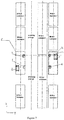
- Figures 7 and 8 respectively schematically illustrate embodiments where a container in 45 feet length and a container in 20 feet length are scanned.
- the ray inspection method may be performed while stacking the container. That is, the ray inspection method according to the present disclosure may further include: when the container transfer apparatus performs stacking operation to the container in the container yard, positioning a container to be inspected by using the container transfer apparatus in an inspection region of the movable ray inspection system, and then turning on the ray generator device of the movable ray inspection system and controlling the driving device of the movable ray inspection system to drive the movable ray inspection system to move at a preset velocity along the scanning passage to scan the container to be inspected along a length direction of the container.
- the ray inspection method according to the present disclosure may further be implemented when the container transfer apparatus is in an idle state (for example, at night). That is, the ray inspection method according to the present disclosure may further include: when the container transfer apparatus is in an idle state where no stacking operation is performed, positioning a container to be inspected by using the container transfer apparatus in an inspection region of the movable ray inspection system, and then turning on the ray generator device of the movable ray inspection system and controlling the driving device of the movable ray inspection system to drive the movable ray inspection system to move at a preset velocity along the scanning passage to scan the container to be inspected along a length direction of the container.
- the ray inspection method according to the present disclosure may allow inspection time to be flexibly planned according to requirement of routine schedule of the container yard.
- the movable ray inspection method according to the present disclosure may further include:
- the ray inspection method according to the present disclosure may further include:
- all components of the inspection system are mounted in one or more container-like chamber and the one or more chamber are stacked with other standard container in a container yard and, when (for example, lifting machine) works, will be hoisted and passed through the inspection system, achieving the scanning to the container.
- the container inspection system may be directly arranged in a container yard without provision of additional or dedicated place for apparatus, and an amount of place may be saved.
- the movable ray inspection system and the ray inspection method according to embodiments of the present disclosure do not require transferring a container by a vehicle to a separated location or an operation field, and may be directly mounted in a container yard and control the movable ray inspection system itself to complete scan, thereby further increasing inspection efficiency.
- the container-like chambers of the movable ray inspection system according to the present disclosure may be conveniently transferred to or mounted in another location or field by using an existing lifting machine or other container transfer apparatus, and the container-like chambers of the movable ray inspection system may themselves move, thereby largely reducing difficulty in assembly and transfer of the container inspection system as desired.
Landscapes
- Physics & Mathematics (AREA)
- Life Sciences & Earth Sciences (AREA)
- General Physics & Mathematics (AREA)
- Geophysics (AREA)
- General Life Sciences & Earth Sciences (AREA)
- High Energy & Nuclear Physics (AREA)
- General Health & Medical Sciences (AREA)
- Biochemistry (AREA)
- Immunology (AREA)
- Pathology (AREA)
- Analytical Chemistry (AREA)
- Chemical & Material Sciences (AREA)
- Health & Medical Sciences (AREA)
- Analysing Materials By The Use Of Radiation (AREA)
- Measurement Of Radiation (AREA)
Abstract

Description
- The present application claims priority to Chinese Patent Application No.
201611164289.6, filed on December 15, 2016 - The present disclosure relates to technical field of container inspection, and particularly to a movable ray inspection system and a ray inspection method for a container mounted in a container yard.
- Currently, many places where containers are stacked, such as a cargo terminal, a wharf, or a port, encounter land shortage. Meanwhile, a conventional container inspection system is relatively large and commonly needs a separated field or place for mounting. However, such a container inspection system not only occupies much valuable space of a port but also causes problems such as long construction period, high cost.
- Further, a conventional container inspection system commonly operates as following: containers are unloaded to a port and transported to a container yard, then, a container to be inspected is transported from the container yard by a vehicle to a field where the inspection system is located and then the container is scanned and inspected; after inspection, the container is transported back to the container yard by the vehicle. Such an inspection process spends time and needs great effort, which reduces efficiency of operation in the container yard. In addition, the conventional container inspection system further needs construction and is hard to assemble and disassemble, and even is non-transferred.
- The present disclosure provides a movable ray inspection system, which can be mounted in a container yard to inspect an object in a container, and a ray inspection method.
- According to an aspect of the present disclosure, there is provided a movable ray inspection system used to be mounted in a container yard to inspect an object within a container, the movable ray inspection system comprising:
- a ray generator device configured to emit a ray, a ray receiving device configured to receive the ray, at least one chamber for receiving the ray generator device and the ray receiving device therein, and a moving device for the movable ray inspection system, the movable ray inspection system being configured to define a scanning passage, characterized in that:
- each of the at least one chamber is configured to be a standard container or a chamber which has a same shape, a same size and a same structure as a standard container, such that the movable ray inspection system is adapted to be stacked in the container yard, and the moving device is configured to allow the movable ray inspection system to move in a preset direction so as to inspect the object within the container.
- In an embodiment, each of the at least one chamber is provided with a hoisting coupling, which is the same as that of the standard container, so as to be hoisted by a container transfer apparatus.
- In an embodiment, the moving device comprises a guide wheel arranged on a bottom surface of the chamber and a guide rail arranged on ground, and the guide wheel is movably fitted on the guide rail; or, the moving device comprises a moving wheel mounted on the bottom surface of the chamber.
- In an embodiment, a height of the moving device is equal to a difference between a height of a high container and a height of a standard container.
- In an embodiment, the movable ray inspection system further includes a driving device configured for driving the movable ray inspection system to move.
- In an embodiment, the movable ray inspection system includes a first chamber, a second chamber and a third chamber, the first chamber is arranged at a side of the scanning passage in the container yard, and the second chamber and the third chamber, stacked up-down with each other, are arranged at the other side of the scanning passage, and
the first chamber is provided with the ray generator device therein, and each of the second chamber and the third chamber is provided with the ray receiving device therein, and the ray generator device and the ray receiving devices are substantially aligned with one another in a second direction perpendicular to a first direction along which the scanning passage extends,
preferably, the first chamber and the third chamber located downside are both provided with the moving devices on their bottom surfaces respectively. - In an embodiment, the movable ray inspection system comprises a first chamber, a second chamber, a third chamber and a fourth chamber, the second chamber and the first chamber, stacked up-down with each other, are arranged at a side of the scanning passage in the container yard, and the third chamber and the fourth chamber, stacked up-down with each other, are arranged at the other side of the scanning passage, and wherein,
each of the first chamber located downside and the fourth chamber located downside is provided with the ray generator device and the ray receiving device therein, and each of the second chamber located upside and the third chamber located upside is provided with the ray receiving device, wherein the ray generator device and the ray receiving device provided in each of the first chamber and the fourth chamber are arranged to space away from each other in the first direction along which the scanning passage extends, and the ray generator device in the first chamber is substantially aligned with the ray receiving devices in the third chamber and the fourth chamber in the second direction perpendicular to the first direction, and the ray receiving devices in the first chamber and the second chambers are substantially aligned with the ray generator device in the fourth chamber in the second direction perpendicular to the first direction;
preferably, the first chamber located downside and the fourth chamber located downside are both provided with the moving devices on their bottom surfaces respectively. - In an embodiment, the movable ray inspection system further comprises a rigid connection device configured to connect the chambers at either side of the scanning passage.
- In an embodiment, the movable ray inspection system comprises a chamber arranged at a side of the scanning passage in the container yard and provided with the ray generator device and the ray receiving device.
- In an embodiment, the movable ray inspection system comprises a chamber arranged at a side of the scanning passage in the container yard and, the ray generator device is disposed within the chamber and comprises a plurality of detectors arranged in a shape of "L", wherein a part of the plurality of detectors are arranged on an inner wall of the chamber and the other part of the plurality of detectors are arranged on a cross bracket perpendicular to the inner wall.
- In an embodiment, the movable ray inspection system includes a first chamber and a second chamber, the first chamber is arranged at a side of the scanning passage in the container yard, and the second chamber is arranged at the other side of the scanning passage, the second chamber is provided with the second ray generator device and the second ray receiving device and the first chamber and the second chamber are provided with the moving devices on their bottom surface.
- In an embodiment, the movable ray inspection system includes a first chamber, a second chamber and a third chamber, the first chamber is arranged at one side of the scanning passage in the container yard, the second chamber is arranged at the other side of the scanning passage in the container yard, and the third chamber is arranged under the scanning passage in the container yard, and wherein the first chamber is provided with the first ray generator device and the first ray receiving device therein, the second chamber is provided with the second ray generator device and the second ray receiving device therein, the third chamber is provided with the third ray generator device and the third ray receiving device therein, and the first, second and third chambers are all provided with the moving devices on their bottom surface.
- In an embodiment, the movable ray inspection system further includes a control device that is in communication with a control system in the container yard and/or a database in the container yard, and the control device is electrically connected with the driving device so as to control the driving device;
preferably, the movable ray inspection system further comprising a photoelectric conversion device configured to convert the ray received by the ray receiving device to a digital signal, the photoelectric conversion device being in communication with the control device so as to transmit image information as the digital signal to the control device;
further preferably, the movable ray inspection system further comprising a container symbol identification device configured to identify contain symbol and be in communication with the control device so as to transmit the identified container symbol information to the control device, the control device being configured to, according to the identified container symbol, read corresponding container information from the control system of the container yard and/or a database of the container yard and to bond the container information to the image information. - According to another aspect, a ray inspection method for inspecting a container in a container yard using the above movable ray inspection system, wherein the method comprises:
- stacking the movable ray inspection system in the container yard by using a container transfer apparatus in the container yard, such that the movable ray inspection system defines a scanning passage; and
- when the container transfer apparatus performs stacking operation to the container in the container yard, turning on the ray generator device of the movable ray inspection system and controlling the movable ray inspection system to move along the scanning passage in the container yard at a preset velocity, so as to scan the container to be inspected along a length direction of a container;
- preferably, further comprising:
- after completing the scanning to a first stack of containers in the container yard, driving the movable ray inspection system to move to a second stack of containers which are located at different position from the first stack of containers in the container yard, so as to scan the second stack of containers.
- In an embodiment, the ray inspection method further includes: when the container transfer apparatus is in an idle state where no stacking operation is performed, turning on the ray generator device of the movable ray inspection system and controlling the movable ray inspection system to move along the scanning passage in the container yard at a preset velocity, so as to scan the container to be inspected along a length direction of a container;
- preferably, further comprising:
- after completing the scanning to a first stack of containers in the container yard, driving the movable ray inspection system to move to a second stack of containers which are located at different position from the first stack of containers in the container yard, so as to scan the second stack of containers.
- In order to make the object, technical scheme and advantages of the present disclosure more definitely, the present disclosure is further described in detail in conjunction with the embodiments with reference to the drawings. In the drawings:
-
Figure 1 is a schematic view of a movable ray inspection system according to an embodiment of the present disclosure, in which the movable ray inspection system includes three chambers, and the ray generator device and the ray receiving device are respectively arranged at either side of a scanning passage; -
Figure 1A is an enlarged partial view of a moving device of the ray inspection device according to an embodiment of the present disclosure; -
Figure 2 is a schematic view of a movable ray inspection system according to an embodiment of the present disclosure, in which the movable ray inspection system includes four chambers, and the ray generator device and the ray receiving device are respectively arranged at either side of a scanning passage; -
Figure 3 is a schematic view of a movable ray inspection system according to an embodiment of the present disclosure, in which the movable ray inspection system includes one chamber, and the ray generator device and the ray receiving device are arranged at the same side of a scanning passage; -
Figure 4 is a schematic view of a movable ray inspection system according to an embodiment of the present disclosure, in which the ray receiving device includes a plurality of detectors arranged in a shape of "L"; -
Figure 5 is a schematic view of a movable ray inspection system according to an embodiment of the present disclosure, in which the movable ray inspection system includes two chambers so as to scan a container from both sides thereof; -
Figure 6 is a schematic view of a movable ray inspection system according to an embodiment of the present disclosure, in which the movable ray inspection system includes three chambers so as to scan a container from a left side, a right side and a downside; -
Figure 7 schematically illustrates an arrangement of a movable ray inspection system according to an embodiment of the present disclosure when scanning a container in 45 feet length; -
Figure 8 schematically illustrates an arrangement of a movable ray inspection system according to an embodiment of the present disclosure when scanning a container in 20 feet length. - Embodiments of the present disclosure will be described in detail hereinafter. It is noted that the embodiments described herein are intended to for exemplar illustration, instead of limitation on the present disclosure. In the following description, an amount of special details are described in order to provide a complete understanding on the present disclosure. However, it is obvious for those skilled in the art that the present invention is not necessary to be implemented with the details herein. In other embodiments of the present disclosure, known structures, circuits, materials or processes are not described for avoiding confusing the present disclosure.
- In this description, "an embodiment", "embodiments", "an example" or "examples" are used to represent features, structures or characteristics described in conjunction with the embodiment or example are included in at least one embodiment of the present disclosure. Thus, the wordings of "in an embodiment", "in the embodiment", "in an example" or "as an example" used in the whole description are not necessary to indicate the same embodiment or example. In addition, the special features, structures or characteristics may be combined in a suitable combination and/or sub-combination in one or more embodiment or example. In addition, it is understood by those skilled in the art that the term of "and/or" used herein includes any of one or more item listed herein that are associated with one another, or combination thereof.
- In the drawings, for easy of description, an XYZ coordinate system is provided, in which X axis represents a direction of a scanning passage in a container yard, i.e., a length direction of a container, Y axis represents a width direction of the container and Z axis represents a height direction of the container.
- In the disclosure, the terms of "first" and "second" do not mean order or difference of importance, but are intended to distinguish different components. In the disclosure, for brief, some devices such as the commonly known processor by those skilled in the art are not described in detail.
-
Figure 1 illustrates a schematic view of a movable ray inspection system according to an embodiment of the present disclosure. The movable ray inspection system is configured to be arranged in a container yard to inspect object(s) in a container. It is noted that, inFigure 1 , in order to clearly illustrate the movable ray inspection system according to the present disclosure, other containers and a lifting mechanical device, etc. in the container yard are omitted. - The movable ray inspection system mainly includes: a ray generator device configured to emit a ray, a ray receiving device configured to receive the ray, and at least one chamber for receiving the ray generator device and the ray receiving device therein. The movable ray inspection system is configured to define a scanning passage. Each of the at least one chamber is configured to be a standard container or a chamber which has a same shape, a same size and a same structure as a standard container such that the movable ray inspection system is adapted to be stacked in the container yard. Herein, "each of the at least one chamber is configured to be a standard container or a chamber which has a same shape, a same size and a same structure as a standard container" means: each chamber has a shape of cuboid like a standard container and size of each chamber (including length, width and height, etc.) are respectively equal to those of the standard container; and, each chamber has the same structure as a standard container, and particularly has an outside coupling structure, for example, each chamber has the same hoisting coupling as a standard container such that each chamber is adapted to be hoisted by an existing lifting mechanism in the container yard. It can be seen that the movable ray inspection system according to embodiments of the present disclosure may be seamlessly mounted with a standard container in the container yard by using an existing lifting mechanism without providing a dedicated space and a special mounting apparatus, and thus the space may be saved and mounting and transfer operations may be simplified.
- In the embodiment as shown in
Figure 1 , the movable ray inspection system includes three chambers, i.e., afirst chamber 11, asecond chamber 12 and athird chamber 13. Thefirst chamber 11 is arranged at a side (right side inFigure 1 ) of the scanning passage P (as shown inFigures 6 and7 ) in the container yard, thesecond chamber 12 and thethird chamber 13 are arranged in up-down manner at the other side (left side inFigure 1 ) of the scanning passage P in the container yard. Aray generator device 2 is disposed in thefirst chamber 11. Theray generator device 2 may be a radiation element such as cobalt-60 , or may be an X-ray generator, or may be an X-ray machine, or also may be a neutron generator. Thesecond chamber 12 and thethird chamber 13 each may be provided with aray receiving device 6 therein, and theray receiving device 6 may include a plurality of detectors, detector array, etc.. - The movable ray inspection system further includes a moving
device 8. In an example, as shown inFigure 1A , the movingdevice 8 includes aguide wheel 81 on the chamber and aguide rail 82 arranged on ground, in which theguide wheel 81 is movably fitted on theguide rail 82. Specifically, thefirst chamber 11 and thethird chamber 13 located on downside are respectively provided with theguide wheels 81 on their low surface, and the guide rails 82 are respectively arranged, corresponding to theguide wheels 81, on ground, such that theguide wheels 81 may be respectively movably fitted on the twoguide rails 82. - The movable ray inspection system may further include a driving device configured for driving the movable ray inspection system to move. In an example, the driving device may include an electric motor, an air motor or a hydraulic motor configured on body (for example, chamber) of the movable ray inspection system, i.e., the movable ray inspection system may be a self-driving or self-pushing device. In another example, the driving device may include a driving trailer or power head outside of the movable ray inspection system, which may be connected with the movable ray inspection system, when used, to pull the movable ray inspection system, that is, the movable ray inspection system may be an external force pushed device or an external force driven device.
- Further, in order to allow the
first chamber 11 and the second,third chamber Figure 1 to move synchronously, or more specifically, to allow theray generator device 2 and the correspondingray receiving device 6 at either side of the scanning passage P to move synchronously, a connection device 9 is provided between thefirst chamber 11 and thethird chamber 13. The connection device 9 may be a rigid connection device, such as a connection rod 91. With this configuration, when the driving device drives thefirst chamber 11 located at right side of the scanning passage P to move along therail 82, due to connection between the chambers at either side of the scanning passage by the connection rod 91, thesecond chamber 12 and thethird chamber 13 at left side of the scanning passage P may move synchronously, that is, theray generator device 2 and the correspondingray receiving device 6 may move synchronously, so as to ensure ray generated by theray generator device 2 may be received by theray receiving device 6. Similarly, when the driving device drives thesecond chamber 12 and thethird chamber 13 at left side of the scanning passage P to move along theguide rail 82, thefirst chamber 11 at right side of the scanning passage P will move synchronously. In the embodiment, due to the rigid connection device, it ensures the chambers at either side of the scanning passage to move synchronously such that, neither the driving devices in all chambers at both side of the scanning passage are provided nor the a complex synchronously-driving mechanism is provided to ensure the chambers at both sides of the scanning passage to synchronously move. - With this configuration, in the embodiment as shown in
Figure 1 , a lifting mechanism lifts a container C to the movable ray inspection system (that is, to be located at a position between the ray generator device and the ray receiving device in the scanning passage). Upon driving of the driving device of the movable ray inspection system, thechambers - It is noted that, although the moving device includes the guide wheels and the guide rails and the guide rails are in shape of "" in the embodiment as shown in

Figure 1 , the moving device according to the present disclosure is not limited to this. For example, in an alternated embodiment, the moving device may include a guide rail in other shape, or may include a guide rail and a side block, or the moving device may be a wheel moving device, that is, the moving device may include movable wheel at bottom portion of the chambers. - As shown in
Figure 1 , thefirst chamber 11 may be further provided with a collimator 4 therein, and theray generator device 2, the collimator 4 and theray receiving device 6 are substantially aligned with one another in a second direction (Y axis direction) perpendicular to the first direction (X axis direction as shown inFigure 6 ) of the scanning passage P, such that ray emitted by theray generator device 2 may be received by theray receiving device 6. In other words, theray generator device 2, the collimator 4 and theray receiving device 6 are substantially located in a same plane perpendicular to the first direction of the scanning passage P. Furthermore, theray generator device 2 is configured such that the ray emitted by theray generator device 2 can scan the entire container C along the height direction (Z axis direction as shown inFigure 1 ) of the container. It is understood for those skilled in the art that the container C may be hanged by a lifting mechanism in the container yard. - Further, in an embodiment, a height of the moving device 8 (i.e., the height in Z direction of the moving device including the
guide wheel 81 and theguide rail 82 as shown inFigure 1 ) is equal to a difference between the height of the high container and that of the standard container. Since a height of the chamber of the movable ray inspection system is usually equal to the height of the standard container, a sum of the height of the moving device and that of the chamber is just equal to the height of the high container when the chamber of the movable ray inspection system is mounted on the guide rail. That is, the arrangement of the moving device and the chamber still meets the requirement in terms of size in the container yard and thus does not interrupt the stacking of the other containers in the container yard. - As shown in
Figure 1 , thechambers protective devices protective devices - It is noted that, as the movable ray inspection system according to the present disclosure may be mounted in a container yard by a lifting mechanism in the container yard and a current normal container yard has substantially been achieved fully mechanical, automatic operation, i.e., no special operator is needed here, compared to the container inspection system in prior art which is needed to be transferred to a dedicated container inspection system by a dedicated person-driven vehicle, the container inspection system according to the disclosure reduces requirement of radiation protection, and thus may have a simplified structure and reduced product cost.
-
Figure 2 illustrates a schematic view of a movable ray inspection system according to another embodiment of the present disclosure. For avoiding repeatedly description, the following description is mainly related to differences of this embodiment from the embodiment as shown inFigure 1 . - As shown in
Figure 2 , the movable ray inspection system includes four chambers, i.e., afirst chamber 11, a second chamber 11', athird chamber 12 and afourth chamber 13, the second chamber 11' and thefirst chamber 11 are arranged in an up-down stack manner at a side of a scanning passage P in the container yard, and thethird chamber 12 and thefourth chamber 13 are arranged in an up-down stack manner at the other side of the scanning passage P in the container yard. - In combination with
Figures 2 and6 , thefirst chamber 11 is located under the second chamber 11', thefourth chamber 13 is located under thethird chamber 12, thefirst chamber 11 located downside and thefourth chamber 13 located downside are each provided with theray generator device 2 and theray receiving device 6. It is noted that theray receiving device 6 in thefourth chamber 13 inFigure 2 is not shown as it is blocked. The second chamber 11' located upside and thethird chamber 12 located upside are each provided with aray receiving device 6 therein. As shown inFigure 6 , theray generator device 2 and theray receiving device 6 arranged in each of thefirst chamber 11 located downside and thefourth chamber 13 located downside are configured to space from each other in the X axis direction. As shown inFigure 2 , theray generator device 2 in thefirst chamber 11 substantially aligns with theray receiving devices 6 in thethird chamber 12 and thefourth chamber 13 in the Y axis direction, i.e., theray generator device 2 in thefirst chamber 11 is substantially located in a same YZ plane as theray receiving devices 6 in thethird chamber 12 and thefourth chamber 13, and theray receiving devices 6 in thefirst chamber 11 and the second chamber 11' align with theray generator device 2 in thefourth chamber 13 in the Y direction, i.e., theray receiving devices 6 in thefirst chamber 11 and the second chamber 11' are substantially located in a same YZ plane as theray generator device 2 in thefourth chamber 13. With this configuration, the ray emitted by theray generator device 2 in thefirst chamber 11 is received by theray receiving devices 6 in thethird chamber 12 and thefourth chamber 13, and the ray emitted by theray generator device 2 in thefourth chamber 13 is received by theray receiving devices 6 in thefirst chamber 11 and the second chamber 11'. - In the embodiment, the movable ray inspection system may also include the moving
device 8, the connection device 9 and the driving device, which are the same as the corresponding components in the above embodiment and are not repeatedly described. With this configuration, when the container C is hanged in the movable ray inspection system and the movable ray inspection system located at either side of the container C synchronously mover, the container C may be scanned and inspected from both sides of the container C synchronously, thereby allowing further effective inspection on the container C. - The above embodiments provide implementations in which the ray generator device and the ray receiving device of the movable ray inspection system are arranged at either side of the scanning passage, i.e., the movable ray inspection system is implemented in ray transmission manner. The movable ray inspection system according to the present disclosure may be implemented in ray back-scattering manner, and is described in detail below in conjunction with
Figures 3-6 . - In the embodiment as shown in
Figure 3 , a movable ray inspection system includes onechamber 30 arranged at a side of a scanning passage P in a container yard, and aray generator device 20 and aray receiving device 60 are arranged in thechamber 30. That is, theray generator device 20 and theray receiving device 60 are arranged at the same side of the scanning passage P and they are in thechamber 30. Thechamber 30 is the same as the above chamber and is configured to be a standard container or is configured to have a same shape, a same size and a same structure as a standard container. Theray generator device 20 is configured such that the ray emitted by theray generator device 20 may scan the entire container C in a height direction (the Z axis direction as shown inFigure 3 ) of the container. It is understood for those skilled in the art that the container C is hoisted by a lifting mechanism in the container yard. Similar to the embodiment as shown inFigure 1 , the ray inspection device may further include the movingdevice 8, the movingdevice 8 may include theguide wheels 81 disposed on the bottom surface of thechamber 30, the guide rails 82 may be provided on ground corresponding to theguide wheels 81 and theguide wheels 81 may movably fitted on theguide rail 82. Different from the embodiment as shown inFigure 1 , in the embodiment as shown inFigure 3 , since theray generator device 20 and theray receiving device 60 of the movable ray inspection system are arranged at the same side of the scanning passage, it is not necessary to provide a connection device in the movable ray inspection system to ensure theray generator device 20 and theray receiving device 60 to move synchronously. In addition, it is understood that the movable ray inspection system further includes a driving device, which is the same as the driving device in the above embodiment in terms of working principle and structure and is not repeatedly described for brief. - As such, in the embodiment as shown in
Figure 3 , when the lifting mechanism lifts the container C at a position in the scanning passage P, facing the movable ray inspection system, under driving of the driving device of the movable ray inspection system, thechamber 30 at one side of the scanning passage P moves at the preset velocity along the scanning passage P so as to scan and inspect the container C. - Although not shown in
Figure 3 , it is understood that the movable ray inspection system inFigure 3 may also include the above ray protective device. -
Figure 4 illustrates a schematic view of a movable ray inspection system according to another embodiment of the present disclosure. For avoiding repeating description, the following context mainly relates to difference of the embodiment fromFigure 3 . - As shown in
Figure 4 , the movable ray inspection device includes aray receiving device 60, which includes a plurality of detectors arranged in a shape of "L". Specifically, a part of the detectors are arranged on the verticalinner wall 31 of thechamber 30 while the other detectors are arranged on a cross bracket perpendicular to the vertical inner wall. -
Figure 5 illustrates a schematic view of a movable ray inspection system according to another embodiment of the present disclosure. For avoiding repeating description, the following context mainly relates to difference of the embodiment fromFigure 3 . In the embodiment as shown inFigure 5 , the movable ray inspection system includes twochambers 30, 30', and thechamber 30, 30' are respectively arranged at a right side and a left side of the scanning passage P in the container yard. Aray generator device 20 and aray receiving device 60 are provided in thechamber 30, and a ray generator device 20' and a ray receiving device 60' are provided in the chamber 30'. In the embodiment, the ray emitted by theray generator device 20 is received by theray receiving device 60, and the ray emitted by the ray generator device 20' is received by the ray receiving device 60'. The movable ray inspection system further includes movingdevices 8 arranged at thechambers 30, 30'. Scan and inspection on the container C thus may be performed at both sides of the container C by configuring back-scattering movable ray inspection system at both sides of the scanning passage P, thereby achieving more effective inspection on the container C. -
Figure 6 illustrates a schematic view of a movable ray inspection system according to another embodiment of the present disclosure. For avoiding repeating description, the following context mainly relates to difference of the embodiment fromFigure 3 . - In the embodiment as shown in
Figure 6 , the movable ray inspection system includes threechambers chambers 30, 30' are similar to those in the embodiment as shown inFigure 5 and thechamber 30" is provided with aray generator device 20" and aray receiving device 60". As shown inFigure 6 , thechamber 30" is arranged under the container C to be inspected so as to scan and inspect the container C from downside thereof. The movable ray inspection system further includes movingdevices 8 respectively disposed at thechambers - It is understood that, in order to mounting of the
chamber 30", a recess (not shown) may be made in the ground under the scanning passage P and thechamber 30" is arranged in the recess; or, thechamber 30" may be placed on ground while thechambers 30, 30' are arranged on locations in higher level. In the latter situation, the container C to be inspected will be hoisted in higher level by the lifting mechanism when passing through the scanning passage P so as to allow scan and inspection on the container C to be performed at the downside of the container C. - Various embodiments of the movable ray inspection system of the present disclosure are described above in conjunction with
Figures 1-6 . Common components of those movable ray inspection systems according to the embodiments of the present disclosure will be further described. - Although not shown, it is understood that a control system configured to control apparatuses, mechanisms and devices in the container yard is provided in the container yard. The movable ray inspection system according to the present disclosure further includes a control device that is in communication with the control system of the container yard and/or a database of the container yard so as to achieve signal and date transmission with the control system of the container yard. Further, the control system may be electrical connected with the above driving device to control the driving device.
- In an embodiment, the movable ray inspection system further includes a photoelectric conversion device configured to convert the ray received by the ray receiving device to digital signal, and the photoelectric conversion device is in communication with the control device to transmit image information to the control device.
- In an embodiment, the movable ray inspection system further includes a container symbol identification device 50 (as shown in
Figure 7 ) that is in communication with the control device so as to transmit the identified container symbol information of the container to the control device. The control device is further configured to read the corresponding container information from the control system of the container yard and/or a database of the container yard according to the identified container symbol, and to bond the container information to the image information. - Further, the movable ray inspection system may further include a power distribution device configured to supply electrical power and/or perform power distribution to electronic devices in the chambers of the movable ray inspection system.
- Further, the control device of the movable ray inspection system includes a processor configured to communicate with other associated systems and to perform analyzing and processing on the image and/or data captured by the movable ray inspection system.
- A ray inspection method for inspecting a container in a container yard by using the above described movable ray inspection system will be described in conjunction with
Figures 7∼8 . The method may include: stacking the movable ray inspection system in the container yard by using a container transfer apparatus (for example, a lifting mechanism, etc.) in the container yard. In the embodiment as shown inFigures 7 and8 , thechambers Figures 7 and8 respectively schematically illustrate embodiments where a container in 45 feet length and a container in 20 feet length are scanned. - In an embodiment, the ray inspection method may be performed while stacking the container. That is, the ray inspection method according to the present disclosure may further include: when the container transfer apparatus performs stacking operation to the container in the container yard, positioning a container to be inspected by using the container transfer apparatus in an inspection region of the movable ray inspection system, and then turning on the ray generator device of the movable ray inspection system and controlling the driving device of the movable ray inspection system to drive the movable ray inspection system to move at a preset velocity along the scanning passage to scan the container to be inspected along a length direction of the container.
- Further, the ray inspection method according to the present disclosure may further be implemented when the container transfer apparatus is in an idle state (for example, at night). That is, the ray inspection method according to the present disclosure may further include: when the container transfer apparatus is in an idle state where no stacking operation is performed, positioning a container to be inspected by using the container transfer apparatus in an inspection region of the movable ray inspection system, and then turning on the ray generator device of the movable ray inspection system and controlling the driving device of the movable ray inspection system to drive the movable ray inspection system to move at a preset velocity along the scanning passage to scan the container to be inspected along a length direction of the container.
- It can be seen that the ray inspection method according to the present disclosure may allow inspection time to be flexibly planned according to requirement of routine schedule of the container yard.
- In one embodiment,
the movable ray inspection method according to the present disclosure may further include: - identifying the container symbol on the container that is being scanned;
- reading the corresponding container information from the control system of the container yard and/or the database of the container yard according to the container symbol; and
- bonding the container information to image information obtained by scanning of the movable ray inspection system.
- In order to transfer the movable ray inspection system according to the present disclosure to another location, the ray inspection method according to the present disclosure may further include:
- after completing the scanning to a first stack of containers in the container yard, transferring the movable ray inspection system to a second stack of containers which are located at different position from the first stack of containers in the container yard by using the container transfer apparatus in the container yard, so as to scan the second stack of containers. With the simple operation, transfer of the movable ray inspection system may be achieved without a dedicated transportation apparatus and transferring efficiency may be increased.
- In the movable ray inspection system and the ray inspection method according to embodiments of the present disclosure, all components of the inspection system are mounted in one or more container-like chamber and the one or more chamber are stacked with other standard container in a container yard and, when (for example, lifting machine) works, will be hoisted and passed through the inspection system, achieving the scanning to the container. The container inspection system may be directly arranged in a container yard without provision of additional or dedicated place for apparatus, and an amount of place may be saved. Further, the movable ray inspection system and the ray inspection method according to embodiments of the present disclosure do not require transferring a container by a vehicle to a separated location or an operation field, and may be directly mounted in a container yard and control the movable ray inspection system itself to complete scan, thereby further increasing inspection efficiency. Further, the container-like chambers of the movable ray inspection system according to the present disclosure may be conveniently transferred to or mounted in another location or field by using an existing lifting machine or other container transfer apparatus, and the container-like chambers of the movable ray inspection system may themselves move, thereby largely reducing difficulty in assembly and transfer of the container inspection system as desired.
- Although the present disclosure is described with reference to several typical embodiments, it is understood that the terms as used are illustrative and exemplary terms, instead of limitation terms. As the present invention may be implemented in a plurality of embodiments without departed from the spirit of the present disclosure, it is understood that the above embodiments are not limited to the above detail, but shall be interpreted widely within the spirit and scope defined by the claims. Thus, all changes and modifications of the embodiments which fall into the scope or equivalent of the claims shall be covered by the attached claims.
Claims (15)
- A movable ray inspection system used to be mounted in a container yard to inspect an object within a container, the movable ray inspection system comprising:a ray generator device configured to emit a ray, a ray receiving device configured to receive the ray, at least one chamber for receiving the ray generator device and the ray receiving device therein, and a moving device for the movable ray inspection system, the movable ray inspection system being configured to define a scanning passage, characterized in that:each of the at least one chamber is configured to be a standard container or a chamber which has a same shape, a same size and a same structure as a standard container, such that the movable ray inspection system is adapted to be stacked in the container yard, and the moving device is configured to allow the movable ray inspection system to move in a preset direction so as to inspect the object within the container.
- The movable ray inspection system according to claim 1, wherein each of the at least one chamber is provided with a hoisting coupling, which is the same as that of the standard container, so as to be hoisted by a container transfer apparatus.
- The movable ray inspection system according to claim 1 or 2, wherein the moving device comprises a guide wheel arranged on a bottom surface of the chamber and a guide rail arranged on ground, and the guide wheel is movably fitted on the guide rail; or, the moving device comprises a moving wheel mounted on the bottom surface of the chamber.
- The movable ray inspection system according to any one of claims 1-3, wherein a height of the moving device is equal to a difference between a height of a high container and a height of a standard container.
- The movable ray inspection system according to any one of claims 1-4, further comprising a driving device configured for driving the movable ray inspection system to move.
- The movable ray inspection system according to any one of claims 1-5, wherein the movable ray inspection system includes a first chamber, a second chamber and a third chamber, the first chamber is arranged at a side of the scanning passage in the container yard, and the second chamber and the third chamber, stacked up-down with each other, are arranged at the other side of the scanning passage, and
the first chamber is provided with the ray generator device therein, and each of the second chamber and the third chamber is provided with the ray receiving device therein, and the ray generator device and the ray receiving devices are substantially aligned with one another in a second direction perpendicular to a first direction along which the scanning passage extends,
preferably, the first chamber and the third chamber located downside are both provided with the moving devices on their bottom surfaces respectivel y. - The movable ray inspection system according to any one of claims 1-5, wherein the movable ray inspection system comprises a first chamber, a second chamber, a third chamber and a fourth chamber, the second chamber and the first chamber, stacked up-down with each other, are arranged at a side of the scanning passage in the container yard, and the third chamber and the fourth chamber, stacked up-down with each other, are arranged at the other side of the scanning passage, and wherein,
each of the first chamber located downside and the fourth chamber located downside is provided with the ray generator device and the ray receiving device therein, and each of the second chamber located upside and the third chamber located upside is provided with the ray receiving device, wherein the ray generator device and the ray receiving device provided in each of the first chamber and the fourth chamber are arranged to space away from each other in the first direction along which the scanning passage extends, and the ray generator device in the first chamber is substantially aligned with the ray receiving devices in the third chamber and the fourth chamber in the second direction perpendicular to the first direction, and the ray receiving devices in the first chamber and the second chambers are substantially aligned with the ray generator device in the fourth chamber in the second direction perpendicular to the first direction;
preferably, the first chamber located downside and the fourth chamber located downside are both provided with the moving devices on their bottom surfaces respectively. - The movable ray inspection system according to claim 6 or 7, wherein the movable ray inspection system further comprises a rigid connection device configured to connect the chambers at either side of the scanning passage.
- The movable ray inspection system according to any one of claims 1-5, wherein the movable ray inspection system comprises a chamber arranged at a side of the scanning passage in the container yard and provided with the ray generator device and the ray receiving device.
- The movable ray inspection system according to any one of claims 1-5, wherein the movable ray inspection system comprises a chamber arranged at a side of the scanning passage in the container yard and, the ray generator device is disposed within the chamber and comprises a plurality of detectors arranged in a shape of "L", wherein a part of the plurality of detectors are arranged on an inner wall of the chamber and the other part of the plurality of detectors are arranged on a cross bracket perpendicular to the inner wall.
- The movable ray inspection system according to any one of claims 1-5, wherein the movable ray inspection system includes a first chamber and a second chamber, the first chamber is arranged at a side of the scanning passage in the container yard, and the second chamber is arranged at the other side of the scanning passage, the second chamber is provided with the second ray generator device and the second ray receiving device and the first chamber and the second chamber are provided with the moving devices on their bottom surface.
- The movable ray inspection system according to any one of claims 1-5, wherein the movable ray inspection system includes a first chamber, a second chamber and a third chamber, the first chamber is arranged at one side of the scanning passage in the container yard, the second chamber is arranged at the other side of the scanning passage in the container yard, and the third chamber is arranged under the scanning passage in the container yard, and wherein the first chamber is provided with the first ray generator device and the first ray receiving device therein, the second chamber is provided with the second ray generator device and the second ray receiving device therein, the third chamber is provided with the third ray generator device and the third ray receiving device therein, and the first, second and third chambers are all provided with the moving devices on their bottom surface.
- The movable ray inspection system according to claim 5, further comprising a control device that is in communication with a control system in the container yard and/or a database in the container yard, and the control device is electrically connected with the driving device so as to control the driving device;
preferably, the movable ray inspection system further comprising a photoelectric conversion device configured to convert the ray received by the ray receiving device to a digital signal, the photoelectric conversion device being in communication with the control device so as to transmit image information as the digital signal to the control device;
further preferably, the movable ray inspection system further comprising a container symbol identification device configured to identify contain symbol and be in communication with the control device so as to transmit the identified container symbol information to the control device, the control device being configured to, according to the identified container symbol, read corresponding container information from the control system of the container yard and/or a database of the container yard and to bond the container information to the image information. - A ray inspection method for inspecting a container in a container yard using the movable ray inspection system according to any one of claims 1-13, characterized in that, the method comprises:stacking the movable ray inspection system in the container yard by using a container transfer apparatus in the container yard, such that the movable ray inspection system defines a scanning passage; andwhen the container transfer apparatus performs stacking operation to the container in the container yard, turning on the ray generator device of the movable ray inspection system and controlling the movable ray inspection system to move along the scanning passage in the container yard at a preset velocity, so as to scan the container to be inspected along a length direction of a container;preferably, further comprising:after completing the scanning to a first stack of containers in the container yard, driving the movable ray inspection system to move to a second stack of containers which are located at different position from the first stack of containers in the container yard, so as to scan the second stack of containers.
- The ray inspection method according to claim 14, further comprising:when the container transfer apparatus is in an idle state where no stacking operation is performed, turning on the ray generator device of the movable ray inspection system and controlling the movable ray inspection system to move along the scanning passage in the container yard at a preset velocity, so as to scan the container to be inspected along a length direction of a container;preferably, further comprising:after completing the scanning to a first stack of containers in the container yard, driving the movable ray inspection system to move to a second stack of containers which are located at different position from the first stack of containers in the container yard, so as to scan the second stack of containers.
Applications Claiming Priority (1)
| Application Number | Priority Date | Filing Date | Title |
|---|---|---|---|
| CN201611164289.6A CN106526687A (en) | 2016-12-15 | 2016-12-15 | Movable ray inspection system and ray inspection method for container |
Publications (1)
| Publication Number | Publication Date |
|---|---|
| EP3336587A1 true EP3336587A1 (en) | 2018-06-20 |
Family
ID=58339936
Family Applications (1)
| Application Number | Title | Priority Date | Filing Date |
|---|---|---|---|
| EP17204392.9A Withdrawn EP3336587A1 (en) | 2016-12-15 | 2017-11-29 | Movable ray inspection system and ray inspection method for a container |
Country Status (9)
| Country | Link |
|---|---|
| US (1) | US10782246B2 (en) |
| EP (1) | EP3336587A1 (en) |
| CN (1) | CN106526687A (en) |
| DE (1) | DE102017011133A1 (en) |
| FR (1) | FR3060770B1 (en) |
| GB (1) | GB2559033B (en) |
| MY (1) | MY199023A (en) |
| SG (1) | SG10201709939YA (en) |
| WO (1) | WO2018107935A1 (en) |
Families Citing this family (8)
| Publication number | Priority date | Publication date | Assignee | Title |
|---|---|---|---|---|
| CN106526687A (en) * | 2016-12-15 | 2017-03-22 | 同方威视技术股份有限公司 | Movable ray inspection system and ray inspection method for container |
| CN107860782A (en) * | 2017-09-22 | 2018-03-30 | 北京华力兴科技发展有限责任公司 | Portable commodity inspection system |
| CN108227027B (en) * | 2017-12-29 | 2020-12-01 | 同方威视技术股份有限公司 | Vehicle Backscatter Inspection System |
| CN108008458B (en) * | 2017-12-29 | 2020-09-08 | 同方威视技术股份有限公司 | Vehicle-mounted backscatter inspection system |
| CN108490495A (en) * | 2018-04-04 | 2018-09-04 | 同方威视技术股份有限公司 | Container check system, conveyer method and port facilities |
| CN114779359A (en) * | 2022-04-12 | 2022-07-22 | 北京华力兴科技发展有限责任公司 | Trailer type vehicle-mounted inspection system and inspection method |
| CN115185008A (en) * | 2022-07-20 | 2022-10-14 | 北京华力兴科技发展有限责任公司 | A mobile detection system and detection method |
| CN116224462A (en) * | 2022-10-28 | 2023-06-06 | 同方威视技术股份有限公司 | Self-inspection method, device and electronic equipment for inspection equipment |
Citations (4)
| Publication number | Priority date | Publication date | Assignee | Title |
|---|---|---|---|---|
| US20020136353A1 (en) * | 2000-03-01 | 2002-09-26 | Kejun Kang | Container inspection apparatus |
| NZ562090A (en) * | 2006-12-11 | 2009-04-30 | American Science & Eng Inc | X-ray backscatter detection imaging modules |
| US20090147913A1 (en) * | 2006-04-13 | 2009-06-11 | Grohmann Technologies Gmbh | X-ray scanner |
| CN106226338A (en) * | 2016-09-20 | 2016-12-14 | 同方威视技术股份有限公司 | Ray inspection system and inspection method for container |
Family Cites Families (14)
| Publication number | Priority date | Publication date | Assignee | Title |
|---|---|---|---|---|
| JP3269319B2 (en) | 1995-03-28 | 2002-03-25 | 株式会社日立製作所 | X-ray CT inspection equipment for containers |
| USRE39396E1 (en) * | 1996-02-12 | 2006-11-14 | American Science And Engineering, Inc. | Mobile x-ray inspection system for large objects |
| CN2410260Y (en) * | 2000-03-01 | 2000-12-13 | 清华大学 | Detachable combined movable container detector |
| US7486768B2 (en) * | 2002-07-23 | 2009-02-03 | Rapiscan Security Products, Inc. | Self-contained mobile inspection system and method |
| US20090257555A1 (en) * | 2002-11-06 | 2009-10-15 | American Science And Engineering, Inc. | X-Ray Inspection Trailer |
| CN200982954Y (en) * | 2006-12-14 | 2007-11-28 | 清华大学 | A check device of moveable cantilever gate container |
| US20130321622A1 (en) * | 2012-06-01 | 2013-12-05 | Steven Safreno | Shipping container scanning system |
| CN202757895U (en) * | 2012-07-04 | 2013-02-27 | 同方威视技术股份有限公司 | Gantry structure used for combined movable radiation inspection system |
| DE102012222345A1 (en) * | 2012-12-05 | 2014-06-05 | Smiths Heimann Gmbh | X-ray inspection system, in particular mobile X-ray inspection system for large-volume goods |
| CN104749649B (en) * | 2013-12-26 | 2019-02-22 | 同方威视技术股份有限公司 | An inspection system for containers |
| WO2016064913A1 (en) * | 2014-10-21 | 2016-04-28 | Decision Sciences International Corporation | Scalable configurations for multimode passive detection system |
| GB2551720B8 (en) | 2016-06-27 | 2018-05-30 | Airport Capacity Solutions Ltd | Transportable baggage screening module |
| CN206515488U (en) * | 2016-12-15 | 2017-09-22 | 同方威视技术股份有限公司 | Packaged type ray inspection system for container |
| CN106526687A (en) * | 2016-12-15 | 2017-03-22 | 同方威视技术股份有限公司 | Movable ray inspection system and ray inspection method for container |
-
2016
- 2016-12-15 CN CN201611164289.6A patent/CN106526687A/en active Pending
-
2017
- 2017-11-14 WO PCT/CN2017/110830 patent/WO2018107935A1/en not_active Ceased
- 2017-11-29 EP EP17204392.9A patent/EP3336587A1/en not_active Withdrawn
- 2017-11-30 FR FR1761411A patent/FR3060770B1/en active Active
- 2017-11-30 US US15/827,739 patent/US10782246B2/en active Active
- 2017-11-30 MY MYPI2017704613A patent/MY199023A/en unknown
- 2017-11-30 SG SG10201709939YA patent/SG10201709939YA/en unknown
- 2017-11-30 GB GB1719990.2A patent/GB2559033B/en active Active
- 2017-12-01 DE DE102017011133.2A patent/DE102017011133A1/en not_active Withdrawn
Patent Citations (4)
| Publication number | Priority date | Publication date | Assignee | Title |
|---|---|---|---|---|
| US20020136353A1 (en) * | 2000-03-01 | 2002-09-26 | Kejun Kang | Container inspection apparatus |
| US20090147913A1 (en) * | 2006-04-13 | 2009-06-11 | Grohmann Technologies Gmbh | X-ray scanner |
| NZ562090A (en) * | 2006-12-11 | 2009-04-30 | American Science & Eng Inc | X-ray backscatter detection imaging modules |
| CN106226338A (en) * | 2016-09-20 | 2016-12-14 | 同方威视技术股份有限公司 | Ray inspection system and inspection method for container |
Non-Patent Citations (1)
| Title |
|---|
| RODERICK D SWIFT: "PROCEEDINGS OF SPIE Conceptual development of a transportable/deployable x-ray inspection system for cars and vans Conceptual Development of a Transportable/Deployable X-ray Inspection System for Cars and Vans", 6 February 1997 (1997-02-06), XP055401599, Retrieved from the Internet <URL:https://www.spiedigitallibrary.org/conference-proceedings-of-spie/2936/1/Conceptual-development-of-a-transportable-deployable-x-ray-inspection-system/10.1117/12.266263.full?SSO=1> [retrieved on 20170828] * |
Also Published As
| Publication number | Publication date |
|---|---|
| US20180172604A1 (en) | 2018-06-21 |
| US10782246B2 (en) | 2020-09-22 |
| DE102017011133A1 (en) | 2018-06-21 |
| GB201719990D0 (en) | 2018-01-17 |
| WO2018107935A1 (en) | 2018-06-21 |
| GB2559033B (en) | 2020-07-08 |
| CN106526687A (en) | 2017-03-22 |
| FR3060770A1 (en) | 2018-06-22 |
| FR3060770B1 (en) | 2023-02-10 |
| GB2559033A (en) | 2018-07-25 |
| MY199023A (en) | 2023-10-10 |
| SG10201709939YA (en) | 2018-07-30 |
Similar Documents
| Publication | Publication Date | Title |
|---|---|---|
| US10782246B2 (en) | Movable ray inspection system and ray inspection method for a container | |
| EP3296771B1 (en) | Ray inspection system and ray inspection method for a container | |
| EP2531434B1 (en) | Container handler alignment system and method | |
| US20110017693A1 (en) | Container tracking and locating systems, methods, and computer program products | |
| CN112912295A (en) | Moving body | |
| EP3699135B1 (en) | Sensor trolley and corresponding container crane | |
| DE102009008529A1 (en) | Electromagnetic conveyor system for use in laboratory area for transporting carriers with samples, has stator and multiple rollers, which has energy storage unit for providing electrical energy | |
| WO2001065245A1 (en) | Container inspection apparatus | |
| CN111606205B (en) | Container crane comprising a reference mark | |
| WO2018041037A1 (en) | Container inspection system and port facility | |
| CN111017453A (en) | Device for loading and unloading goods | |
| CN207876859U (en) | Inspection of containers transportation system and harbour | |
| CN208522506U (en) | Self-propelling device and wireless charging system based on self-propelling device | |
| CN208722052U (en) | Unmanned logistics vehicle | |
| EP4363264B1 (en) | Charging system for an industrial electric vehicle, method of charging an industrial electric vehicle and use of a charging system | |
| CN206515488U (en) | Packaged type ray inspection system for container | |
| CN201569413U (en) | Automatic dynamic dimension measurement device for motor vehicle rear overhang | |
| CN106596601B (en) | security check system | |
| US20150219786A1 (en) | System for the contactless inspection of containers, particularly iso containers, within a loading and unloading plant | |
| EP4365640A1 (en) | Inspection device and article transfer inspection system | |
| AU2011334123B2 (en) | Method and system for the georeferenced determination of the location of containers in the loading range of container cranes | |
| CN110666769A (en) | Automatic surface treatment system | |
| EP4459270A1 (en) | Radiation inspection system | |
| CN103587850A (en) | Container | |
| US20240047997A1 (en) | Power supply mat, noncontact power supply system, and moving body |
Legal Events
| Date | Code | Title | Description |
|---|---|---|---|
| PUAI | Public reference made under article 153(3) epc to a published international application that has entered the european phase |
Free format text: ORIGINAL CODE: 0009012 |
|
| STAA | Information on the status of an ep patent application or granted ep patent |
Free format text: STATUS: REQUEST FOR EXAMINATION WAS MADE |
|
| 17P | Request for examination filed |
Effective date: 20171129 |
|
| AK | Designated contracting states |
Kind code of ref document: A1 Designated state(s): AL AT BE BG CH CY CZ DE DK EE ES FI FR GB GR HR HU IE IS IT LI LT LU LV MC MK MT NL NO PL PT RO RS SE SI SK SM TR |
|
| AX | Request for extension of the european patent |
Extension state: BA ME |
|
| STAA | Information on the status of an ep patent application or granted ep patent |
Free format text: STATUS: EXAMINATION IS IN PROGRESS |
|
| 17Q | First examination report despatched |
Effective date: 20210915 |
|
| STAA | Information on the status of an ep patent application or granted ep patent |
Free format text: STATUS: THE APPLICATION IS DEEMED TO BE WITHDRAWN |
|
| 18D | Application deemed to be withdrawn |
Effective date: 20220126 |