EP3336461B1 - Refrigeration appliance fan - Google Patents
Refrigeration appliance fan Download PDFInfo
- Publication number
- EP3336461B1 EP3336461B1 EP17207169.8A EP17207169A EP3336461B1 EP 3336461 B1 EP3336461 B1 EP 3336461B1 EP 17207169 A EP17207169 A EP 17207169A EP 3336461 B1 EP3336461 B1 EP 3336461B1
- Authority
- EP
- European Patent Office
- Prior art keywords
- compartment
- fan
- freezer compartment
- ice maker
- refrigeration
- Prior art date
- Legal status (The legal status is an assumption and is not a legal conclusion. Google has not performed a legal analysis and makes no representation as to the accuracy of the status listed.)
- Not-in-force
Links
Images


Classifications
-
- F—MECHANICAL ENGINEERING; LIGHTING; HEATING; WEAPONS; BLASTING
- F25—REFRIGERATION OR COOLING; COMBINED HEATING AND REFRIGERATION SYSTEMS; HEAT PUMP SYSTEMS; MANUFACTURE OR STORAGE OF ICE; LIQUEFACTION SOLIDIFICATION OF GASES
- F25D—REFRIGERATORS; COLD ROOMS; ICE-BOXES; COOLING OR FREEZING APPARATUS NOT OTHERWISE PROVIDED FOR
- F25D11/00—Self-contained movable devices, e.g. domestic refrigerators
- F25D11/02—Self-contained movable devices, e.g. domestic refrigerators with cooling compartments at different temperatures
-
- F—MECHANICAL ENGINEERING; LIGHTING; HEATING; WEAPONS; BLASTING
- F25—REFRIGERATION OR COOLING; COMBINED HEATING AND REFRIGERATION SYSTEMS; HEAT PUMP SYSTEMS; MANUFACTURE OR STORAGE OF ICE; LIQUEFACTION SOLIDIFICATION OF GASES
- F25D—REFRIGERATORS; COLD ROOMS; ICE-BOXES; COOLING OR FREEZING APPARATUS NOT OTHERWISE PROVIDED FOR
- F25D21/00—Defrosting; Preventing frosting; Removing condensed or defrost water
- F25D21/04—Preventing the formation of frost or condensate
-
- F—MECHANICAL ENGINEERING; LIGHTING; HEATING; WEAPONS; BLASTING
- F25—REFRIGERATION OR COOLING; COMBINED HEATING AND REFRIGERATION SYSTEMS; HEAT PUMP SYSTEMS; MANUFACTURE OR STORAGE OF ICE; LIQUEFACTION SOLIDIFICATION OF GASES
- F25D—REFRIGERATORS; COLD ROOMS; ICE-BOXES; COOLING OR FREEZING APPARATUS NOT OTHERWISE PROVIDED FOR
- F25D17/00—Arrangements for circulating cooling fluids; Arrangements for circulating gas, e.g. air, within refrigerated spaces
- F25D17/04—Arrangements for circulating cooling fluids; Arrangements for circulating gas, e.g. air, within refrigerated spaces for circulating air, e.g. by convection
- F25D17/042—Air treating means within refrigerated spaces
- F25D17/047—Pressure equalising devices
-
- F—MECHANICAL ENGINEERING; LIGHTING; HEATING; WEAPONS; BLASTING
- F25—REFRIGERATION OR COOLING; COMBINED HEATING AND REFRIGERATION SYSTEMS; HEAT PUMP SYSTEMS; MANUFACTURE OR STORAGE OF ICE; LIQUEFACTION SOLIDIFICATION OF GASES
- F25D—REFRIGERATORS; COLD ROOMS; ICE-BOXES; COOLING OR FREEZING APPARATUS NOT OTHERWISE PROVIDED FOR
- F25D17/00—Arrangements for circulating cooling fluids; Arrangements for circulating gas, e.g. air, within refrigerated spaces
- F25D17/04—Arrangements for circulating cooling fluids; Arrangements for circulating gas, e.g. air, within refrigerated spaces for circulating air, e.g. by convection
- F25D17/06—Arrangements for circulating cooling fluids; Arrangements for circulating gas, e.g. air, within refrigerated spaces for circulating air, e.g. by convection by forced circulation
- F25D17/062—Arrangements for circulating cooling fluids; Arrangements for circulating gas, e.g. air, within refrigerated spaces for circulating air, e.g. by convection by forced circulation in household refrigerators
-
- F—MECHANICAL ENGINEERING; LIGHTING; HEATING; WEAPONS; BLASTING
- F25—REFRIGERATION OR COOLING; COMBINED HEATING AND REFRIGERATION SYSTEMS; HEAT PUMP SYSTEMS; MANUFACTURE OR STORAGE OF ICE; LIQUEFACTION SOLIDIFICATION OF GASES
- F25D—REFRIGERATORS; COLD ROOMS; ICE-BOXES; COOLING OR FREEZING APPARATUS NOT OTHERWISE PROVIDED FOR
- F25D17/00—Arrangements for circulating cooling fluids; Arrangements for circulating gas, e.g. air, within refrigerated spaces
- F25D17/04—Arrangements for circulating cooling fluids; Arrangements for circulating gas, e.g. air, within refrigerated spaces for circulating air, e.g. by convection
- F25D17/06—Arrangements for circulating cooling fluids; Arrangements for circulating gas, e.g. air, within refrigerated spaces for circulating air, e.g. by convection by forced circulation
- F25D17/062—Arrangements for circulating cooling fluids; Arrangements for circulating gas, e.g. air, within refrigerated spaces for circulating air, e.g. by convection by forced circulation in household refrigerators
- F25D17/065—Arrangements for circulating cooling fluids; Arrangements for circulating gas, e.g. air, within refrigerated spaces for circulating air, e.g. by convection by forced circulation in household refrigerators with compartments at different temperatures
-
- F—MECHANICAL ENGINEERING; LIGHTING; HEATING; WEAPONS; BLASTING
- F25—REFRIGERATION OR COOLING; COMBINED HEATING AND REFRIGERATION SYSTEMS; HEAT PUMP SYSTEMS; MANUFACTURE OR STORAGE OF ICE; LIQUEFACTION SOLIDIFICATION OF GASES
- F25D—REFRIGERATORS; COLD ROOMS; ICE-BOXES; COOLING OR FREEZING APPARATUS NOT OTHERWISE PROVIDED FOR
- F25D29/00—Arrangement or mounting of control or safety devices
-
- F—MECHANICAL ENGINEERING; LIGHTING; HEATING; WEAPONS; BLASTING
- F25—REFRIGERATION OR COOLING; COMBINED HEATING AND REFRIGERATION SYSTEMS; HEAT PUMP SYSTEMS; MANUFACTURE OR STORAGE OF ICE; LIQUEFACTION SOLIDIFICATION OF GASES
- F25B—REFRIGERATION MACHINES, PLANTS OR SYSTEMS; COMBINED HEATING AND REFRIGERATION SYSTEMS; HEAT PUMP SYSTEMS
- F25B2313/00—Compression machines, plants or systems with reversible cycle not otherwise provided for
- F25B2313/031—Sensor arrangements
- F25B2313/0312—Pressure sensors near the indoor heat exchanger
-
- F—MECHANICAL ENGINEERING; LIGHTING; HEATING; WEAPONS; BLASTING
- F25—REFRIGERATION OR COOLING; COMBINED HEATING AND REFRIGERATION SYSTEMS; HEAT PUMP SYSTEMS; MANUFACTURE OR STORAGE OF ICE; LIQUEFACTION SOLIDIFICATION OF GASES
- F25B—REFRIGERATION MACHINES, PLANTS OR SYSTEMS; COMBINED HEATING AND REFRIGERATION SYSTEMS; HEAT PUMP SYSTEMS
- F25B2600/00—Control issues
- F25B2600/11—Fan speed control
- F25B2600/112—Fan speed control of evaporator fans
-
- F—MECHANICAL ENGINEERING; LIGHTING; HEATING; WEAPONS; BLASTING
- F25—REFRIGERATION OR COOLING; COMBINED HEATING AND REFRIGERATION SYSTEMS; HEAT PUMP SYSTEMS; MANUFACTURE OR STORAGE OF ICE; LIQUEFACTION SOLIDIFICATION OF GASES
- F25C—PRODUCING, WORKING OR HANDLING ICE
- F25C2400/00—Auxiliary features or devices for producing, working or handling ice
- F25C2400/10—Refrigerator units
-
- F—MECHANICAL ENGINEERING; LIGHTING; HEATING; WEAPONS; BLASTING
- F25—REFRIGERATION OR COOLING; COMBINED HEATING AND REFRIGERATION SYSTEMS; HEAT PUMP SYSTEMS; MANUFACTURE OR STORAGE OF ICE; LIQUEFACTION SOLIDIFICATION OF GASES
- F25D—REFRIGERATORS; COLD ROOMS; ICE-BOXES; COOLING OR FREEZING APPARATUS NOT OTHERWISE PROVIDED FOR
- F25D2317/00—Details or arrangements for circulating cooling fluids; Details or arrangements for circulating gas, e.g. air, within refrigerated spaces, not provided for in other groups of this subclass
- F25D2317/06—Details or arrangements for circulating cooling fluids; Details or arrangements for circulating gas, e.g. air, within refrigerated spaces, not provided for in other groups of this subclass with forced air circulation
- F25D2317/061—Details or arrangements for circulating cooling fluids; Details or arrangements for circulating gas, e.g. air, within refrigerated spaces, not provided for in other groups of this subclass with forced air circulation through special compartments
-
- F—MECHANICAL ENGINEERING; LIGHTING; HEATING; WEAPONS; BLASTING
- F25—REFRIGERATION OR COOLING; COMBINED HEATING AND REFRIGERATION SYSTEMS; HEAT PUMP SYSTEMS; MANUFACTURE OR STORAGE OF ICE; LIQUEFACTION SOLIDIFICATION OF GASES
- F25D—REFRIGERATORS; COLD ROOMS; ICE-BOXES; COOLING OR FREEZING APPARATUS NOT OTHERWISE PROVIDED FOR
- F25D2317/00—Details or arrangements for circulating cooling fluids; Details or arrangements for circulating gas, e.g. air, within refrigerated spaces, not provided for in other groups of this subclass
- F25D2317/06—Details or arrangements for circulating cooling fluids; Details or arrangements for circulating gas, e.g. air, within refrigerated spaces, not provided for in other groups of this subclass with forced air circulation
- F25D2317/062—Details or arrangements for circulating cooling fluids; Details or arrangements for circulating gas, e.g. air, within refrigerated spaces, not provided for in other groups of this subclass with forced air circulation along the inside of doors
-
- F—MECHANICAL ENGINEERING; LIGHTING; HEATING; WEAPONS; BLASTING
- F25—REFRIGERATION OR COOLING; COMBINED HEATING AND REFRIGERATION SYSTEMS; HEAT PUMP SYSTEMS; MANUFACTURE OR STORAGE OF ICE; LIQUEFACTION SOLIDIFICATION OF GASES
- F25D—REFRIGERATORS; COLD ROOMS; ICE-BOXES; COOLING OR FREEZING APPARATUS NOT OTHERWISE PROVIDED FOR
- F25D2317/00—Details or arrangements for circulating cooling fluids; Details or arrangements for circulating gas, e.g. air, within refrigerated spaces, not provided for in other groups of this subclass
- F25D2317/06—Details or arrangements for circulating cooling fluids; Details or arrangements for circulating gas, e.g. air, within refrigerated spaces, not provided for in other groups of this subclass with forced air circulation
- F25D2317/066—Details or arrangements for circulating cooling fluids; Details or arrangements for circulating gas, e.g. air, within refrigerated spaces, not provided for in other groups of this subclass with forced air circulation characterised by the air supply
- F25D2317/0666—Details or arrangements for circulating cooling fluids; Details or arrangements for circulating gas, e.g. air, within refrigerated spaces, not provided for in other groups of this subclass with forced air circulation characterised by the air supply from the freezer
-
- F—MECHANICAL ENGINEERING; LIGHTING; HEATING; WEAPONS; BLASTING
- F25—REFRIGERATION OR COOLING; COMBINED HEATING AND REFRIGERATION SYSTEMS; HEAT PUMP SYSTEMS; MANUFACTURE OR STORAGE OF ICE; LIQUEFACTION SOLIDIFICATION OF GASES
- F25D—REFRIGERATORS; COLD ROOMS; ICE-BOXES; COOLING OR FREEZING APPARATUS NOT OTHERWISE PROVIDED FOR
- F25D2317/00—Details or arrangements for circulating cooling fluids; Details or arrangements for circulating gas, e.g. air, within refrigerated spaces, not provided for in other groups of this subclass
- F25D2317/06—Details or arrangements for circulating cooling fluids; Details or arrangements for circulating gas, e.g. air, within refrigerated spaces, not provided for in other groups of this subclass with forced air circulation
- F25D2317/068—Details or arrangements for circulating cooling fluids; Details or arrangements for circulating gas, e.g. air, within refrigerated spaces, not provided for in other groups of this subclass with forced air circulation characterised by the fans
- F25D2317/0682—Two or more fans
-
- F—MECHANICAL ENGINEERING; LIGHTING; HEATING; WEAPONS; BLASTING
- F25—REFRIGERATION OR COOLING; COMBINED HEATING AND REFRIGERATION SYSTEMS; HEAT PUMP SYSTEMS; MANUFACTURE OR STORAGE OF ICE; LIQUEFACTION SOLIDIFICATION OF GASES
- F25D—REFRIGERATORS; COLD ROOMS; ICE-BOXES; COOLING OR FREEZING APPARATUS NOT OTHERWISE PROVIDED FOR
- F25D2323/00—General constructional features not provided for in other groups of this subclass
- F25D2323/02—Details of doors or covers not otherwise covered
- F25D2323/021—French doors
-
- F—MECHANICAL ENGINEERING; LIGHTING; HEATING; WEAPONS; BLASTING
- F25—REFRIGERATION OR COOLING; COMBINED HEATING AND REFRIGERATION SYSTEMS; HEAT PUMP SYSTEMS; MANUFACTURE OR STORAGE OF ICE; LIQUEFACTION SOLIDIFICATION OF GASES
- F25D—REFRIGERATORS; COLD ROOMS; ICE-BOXES; COOLING OR FREEZING APPARATUS NOT OTHERWISE PROVIDED FOR
- F25D2700/00—Means for sensing or measuring; Sensors therefor
-
- Y—GENERAL TAGGING OF NEW TECHNOLOGICAL DEVELOPMENTS; GENERAL TAGGING OF CROSS-SECTIONAL TECHNOLOGIES SPANNING OVER SEVERAL SECTIONS OF THE IPC; TECHNICAL SUBJECTS COVERED BY FORMER USPC CROSS-REFERENCE ART COLLECTIONS [XRACs] AND DIGESTS
- Y02—TECHNOLOGIES OR APPLICATIONS FOR MITIGATION OR ADAPTATION AGAINST CLIMATE CHANGE
- Y02B—CLIMATE CHANGE MITIGATION TECHNOLOGIES RELATED TO BUILDINGS, e.g. HOUSING, HOUSE APPLIANCES OR RELATED END-USER APPLICATIONS
- Y02B40/00—Technologies aiming at improving the efficiency of home appliances, e.g. induction cooking or efficient technologies for refrigerators, freezers or dish washers
Definitions
- the present disclosure generally relates to refrigeration appliances, and more particularly, to refrigeration appliances incorporating fans for preventing frost buildup within freezer compartments.
- Freezer compartments within refrigeration appliances may experience a pressure differential relative the surroundings of the refrigeration appliance due to the cooling and circulation of air within the appliance. Such a pressure differential may result in warm and/or humid air entering the freezer compartment. Warm or humid air entering the freezer compartment may result in the formation of frost and ice accumulation. Further, pressure differentials may increase the force required to open a door of the appliance.
- a refrigeration appliance includes a freezer compartment, a refrigeration compartment and an ice maker compartment.
- An example of such a refrigeration appliance is disclosed in patent application US2006/260345 A1 .
- An ice maker return duct fluidly couples the ice maker compartment and the freezer compartment.
- a pressure sensor is positioned within the freezer compartment and is configured to detect a pressure differential between the freezer compartment and an external environment.
- a fan is positioned within the ice maker return duct and is configured to be activated when the pressure within the freezer compartment is lower than the air pressure within the external environment.
- a pressure sensor is positioned within the freezer compartment and is configured to detect an air pressure within the freezer.
- a fan is fluidly coupled with the ice maker compartment and the freezer compartment. The fan is configured to be activated when a pressure differential between the freezer compartment and an external environment is sensed.
- a method of operating a refrigeration appliance includes the steps of sensing negative air pressure, relative to an atmospheric pressure, in the freezer compartment of the refrigeration appliance; activating a fan positioned in the ice maker return duct of the refrigerator to blow air into the freezer compartment; and deactivating the fan once a sensed air pressure in the freezer compartment is about equal to or greater than the atmospheric pressure.
- reference numeral 10 generally designates a refrigeration appliance 10 including a freezer compartment 14, a refrigeration compartment 18 and a ince maker compartment 22.
- the ice maker compartment 22 may be positioned outside of the freezer compartment 14.
- An ice maker supply duct 26 and an ice maker return duct 30 fluidly couple the ice maker compartment 22 with the freezer compartment 14.
- a pressure sensor 34 is positioned within the freezer compartment 14. The sensor 34 is configured to detect a pressure differential between the freezer compartment 14 and an external environment (e.g., the atmosphere) to the refrigeration appliance 10.
- a fan 38 is positioned within the ice maker return duct 30.
- the fan 38 is configured to be activated when the pressure within the freezer compartment 14 is lower than the external environment (i.e., a negative pressure is sensed within the freezer compartment 14).
- a controller 40 is electrically coupled to the fan 38 and the sensor 34 for activating the fan 38.
- the refrigeration appliance 10 is depicted as a French-door bottom-mount refrigerator, but it will be understood that the refrigeration appliance 10 may be a side-by-side refrigerator, a bottom mount refrigerator and/or a top mount refrigerator.
- the refrigeration appliance 10 includes the refrigeration compartment 18 and the freezer compartment 14.
- the refrigeration compartment 18 may be a fresh food compartment configured to store food stuffs and/or perishables at temperatures above freezing (e.g., maintained at about 3° C or about 4° C) for long time period.
- the freezer compartment 14 is maintained at a subzero temperature for long term storage of perishables in a frozen state.
- the refrigeration compartment 18 may have an internal volume greater than the freezer compartment 14.
- the refrigeration appliance 10 includes an evaporator 42 which cools the refrigeration compartment 18 and the freezer compartment 14.
- One or more refrigeration doors 44 are provided for the refrigeration compartment 18 and a freezer door 48 is provided for the freezer compartment 14.
- One of the refrigeration doors 44 may include an ice dispenser 52, which may also include a water dispenser.
- the ice maker compartment 22 is provided in the refrigeration compartment 18. More precisely, in the depicted example, the ice maker compartment 22 is positioned in an upper corner of the refrigeration compartment 18, but it will be understood that the ice maker compartment 22 may be positioned in other locations within the refrigeration compartment 18 without departing from the teachings provided herein.
- the ice maker compartment 22 may be positioned within the refrigeration doors 44 and/or the freezer door 48.
- the ice maker compartment 22 may include an ice maker covering 60.
- the ice maker covering 60 may include a front cover 60A that is insulated to prevent the cold air of the ice maker compartment 22 from passing into the refrigeration compartment 18.
- the ice maker covering 60 defines an opening 60B which mates with a chute 64 of the ice dispenser 52.
- a seal may be provided between the opening 60B and the chute 64 to prevent cold air from passing from the ice maker compartment 22 to the refrigeration compartment 18.
- An ice making apparatus may be positioned within the ice maker covering 60.
- the ice maker compartment 22 may be configured to use cool air provided by the ice maker supply duct 26 to freeze water and dispense the ice through the chute 64.
- the ice maker compartment 22 is maintained at a temperature of 0° C or less in order to form ice, but may not be as cold as the freezer compartment 14.
- the ice maker covering 60 may be integrally formed adjacent the refrigeration compartment 18 during a liner forming process. Alternatively, the ice maker covering 60 may be a separate component from the liner of the refrigeration compartment 18 and attached (e.g., by overhead rails, fasteners, etc.) to the liner.
- the ice maker supply duct 26 extends between the freezer compartment 14 and the ice maker compartment 22.
- the ice maker supply duct 26 fluidly couples the freezer compartment 14 and the ice maker compartment 22.
- the supply duct 26 allows chilled air to pass from the freezer compartment 14 to the ice maker compartment 22.
- the supply duct 26 has a lower air inlet 26A within the freezer compartment 14 and an upper outlet 26B connected to an ice maker fan 70 mounted on the back wall of the ice maker compartment 22.
- the ice maker fan 70 draws cold air from the freezer compartment 14 and forces the cold air into the ice maker compartment 22 to facilitate ice making.
- the ice maker fan 70 may be positioned at the inlet 26A, or anywhere along, the supply duct 26.
- the ice maker fan 70 controls the air flow from the freezer compartment 14 to the ice maker compartment 22 and may be a variable speed fan.
- the ice maker supply duct 26 may be positioned within a rear wall of the refrigeration appliance 10, but may additionally or alternatively be positioned within side walls of the refrigeration appliance 10.
- the ice maker return duct 30 may be positioned within a rear wall of the refrigeration appliance 10.
- the return duct 30 may additionally or alternatively be positioned within side walls of the refrigeration appliance 10.
- the ice maker return duct 30 fluidly couples the freezer compartment 14 and the ice maker compartment 22. In other words, the return duct 30 allows chilled air to pass from the ice maker compartment 22 to the freezer compartment 14.
- the ice maker return air duct 30 includes an upper end 30A connected to the ice maker compartment 22, and a lower end 30B terminating within the freezer compartment 14.
- the fan 38 is positioned within the ice maker return duct 30.
- the fan 38 may be positioned within the upper end 30A, the lower end 30B or anywhere along the return duct 30. Further, the fan 38 may be a fan assembly including a plurality of fans, positioned proximate one another, or spread across the ice maker return duct 30.
- the fan 38 may be configured to blow air from the ice maker compartment 22 into the freezer compartment 14. Further, due to a negative pressure generated by the activation of the fan 38, air from within the refrigeration compartment 18 may be sucked into the ice maker compartment 22 and/or return duct 30 such that air from the refrigeration compartment 18 is blown into the freezer compartment 14.
- the fan 38 may be pulse width modulated in order to adjust a fan speed of the fan 38. For example, the magnitude of the fan speed may be controlled by the controller 40 to increase or decrease the volume of air blown by the fan 38 into the freezer compartment 14.
- the sensor 34 may be positioned within the freezer compartment 14. In the depicted example, the sensor 34 is positioned on a side wall of the freezer compartment 14, but may additionally or alternatively be positioned on a back wall, a top wall and/or a bottom wall of the freezer compartment 14. Further, a plurality of sensors 34 may be positioned throughout, or in a single location, of the freezer compartment 14.
- the sensor 34 may be a pressure sensor, humidity sensor, an airflow (e.g., mass flow) sensor and/or combinations thereof. Further, in examples where a plurality of sensors 34 are utilized, each sensor 34 may be different (e.g., one pressure sensor 34, one humidity sensor 34, one air flow sensor 34).
- the pressure sensor 34 may be a gauge pressure sensor or a differential pressure sensor.
- the pressure sensor examples of the sensor 34 may be analog or digital.
- the sensor 34 is electrically coupled with the controller 40 and configured to communicate data to the controller 40 based on the pressure differential between the freezer compartment 14 and the external environment.
- the refrigeration appliance 10 may utilize a predetermined value of external environment pressure.
- the pressure differential may be calculated using the data provided by the sensor 34 and the predetermined value.
- the value may be based on manufacturer settings, user input settings, or calculated values.
- a user or owner of the refrigeration appliance 10 may input an altitude and/or location (e.g., from which pressure may be looked up, preprogrammed, and/or determined) and the controller 40 may assign the predetermined value based on the input data from the user.
- a differential in the pressure may be determined.
- the controller 40 is configured to activate and/or deactivate the fan 38 based on the pressure differential detected by the pressure sensor 34. For example, if a pressure within the freezer compartment 14 is lower than the external environment (i.e., a pressure differential exists), the controller 40 activates the fan 38 to blow air into the freezer compartment 14. Specifically, if a negative pressure differential (i.e., the pressure within the freezer compartment 14 is lower relative to the external environment) exists, the fan 38 is activated to blow air into the freezer compartment 14.
- the fan speed of the fan 38 may be based on the magnitude of the negative pressure differential sensed. For example, the greater the pressure differential (i.e., the greater the negative pressured sensed in the freezer compartment 14), the greater the fan speed.
- the method 90 may begin with a step 94 of sensing a negative air pressure, relative to an atmospheric pressure, within the freezer compartment 14.
- the sensor 34 is a pressure sensor.
- the controller 40 may compare the data from the sensor 34 and an external sensor 78 to determine if a negative pressure differential exists.
- the fan 38 may be configured to be inactive when the sensed pressure in the freezer compartment 14 is equal to or greater than the external environment pressure.
- step 98 of activating the fan 38 to blow air into the freezer compartment 14 may be performed.
- the controller 40 may control the fan speed based on the sensed magnitude of the pressure differential.
- the fan speed may be adjusted while in use based on a magnitude of the pressure differential if it changes. In other words, the fan speed may be decreased or increased as the magnitude of pressure differential decreases or increases, respectively.
- step 102 of deactivating the fan 38 may be performed.
- the fan 38 may be deactivated once a sensed air pressure in the freezer compartment 14 (e.g., as sensed by the sensor 34) is equal to or greater than the atmospheric pressure (e.g., as sensed by the external sensor 78). It will be understood that the pressure differential at which the controller 40 activates and deactivates the fan 38 may have to reach a predetermined threshold prior to activation and/or deactivation.
- a predetermined threshold may be a 0.01%, 0.1%, 1%, 2%, 5% pressure differential to activate or deactivate the fan 38. Further, the predetermined thresholds for activation and deactivation may be different than one another.
- the sensed air pressure of the freezer compartment 14 may be said to be about equal with the atmospheric pressure if a pressure differential between the two is less than about 10%.
- Use of the present disclosure may offer a variety of advantages.
- the addition of the fan 38 to the return duct 30 may allow for a low manufacturing cost solution which may be implemented in a variety of refrigeration appliance styles.
- the present disclosure is a robust solution to negative pressure generation as the pressure can be equalized regardless of the usage pattern, condition of gaskets around the refrigeration appliance 10, alignment of the doors 44, 48, and/or other fault modes.
- use of the present disclosure may reduce the amount of force used to open the freezer door 48. For example, by reducing the magnitude of the pressure differential between the freezer compartment 14 and the external environment, the force to open the freezer door 48 may be reduced. Such a reduction of force may be advantageous in allowing the refrigeration appliance 10 to meet regulations regarding minimum pull force on the doors 44, 48 while also minimizing the production of frost and ice within the freezer compartment 14.
- the term "coupled” in all of its forms, couple, coupling, coupled, etc. generally means the joining of two components (electrical or mechanical) directly or indirectly to one another. Such joining may be stationary in nature or movable in nature. Such joining may be achieved with the two components (electrical or mechanical) and any additional intermediate members being integrally formed as a single unitary body with one another or with the two components. Such joining may be permanent in nature or may be removable or releasable in nature unless otherwise stated.
Landscapes
- Engineering & Computer Science (AREA)
- Chemical & Material Sciences (AREA)
- Combustion & Propulsion (AREA)
- Physics & Mathematics (AREA)
- Mechanical Engineering (AREA)
- Thermal Sciences (AREA)
- General Engineering & Computer Science (AREA)
- Cold Air Circulating Systems And Constructional Details In Refrigerators (AREA)
Description
- The present disclosure generally relates to refrigeration appliances, and more particularly, to refrigeration appliances incorporating fans for preventing frost buildup within freezer compartments.
- Freezer compartments within refrigeration appliances may experience a pressure differential relative the surroundings of the refrigeration appliance due to the cooling and circulation of air within the appliance. Such a pressure differential may result in warm and/or humid air entering the freezer compartment. Warm or humid air entering the freezer compartment may result in the formation of frost and ice accumulation. Further, pressure differentials may increase the force required to open a door of the appliance.
- According to one feature of the present disclosure, a refrigeration appliance includes a freezer compartment, a refrigeration compartment and an ice maker compartment. An example of such a refrigeration appliance is disclosed in patent application
US2006/260345 A1 . An ice maker return duct fluidly couples the ice maker compartment and the freezer compartment. A pressure sensor is positioned within the freezer compartment and is configured to detect a pressure differential between the freezer compartment and an external environment. A fan is positioned within the ice maker return duct and is configured to be activated when the pressure within the freezer compartment is lower than the air pressure within the external environment. - According to another feature of the present disclosure, a pressure sensor is positioned within the freezer compartment and is configured to detect an air pressure within the freezer. A fan is fluidly coupled with the ice maker compartment and the freezer compartment. The fan is configured to be activated when a pressure differential between the freezer compartment and an external environment is sensed.
- According to yet another feature of the present disclosure, a method of operating a refrigeration appliance includes the steps of sensing negative air pressure, relative to an atmospheric pressure, in the freezer compartment of the refrigeration appliance; activating a fan positioned in the ice maker return duct of the refrigerator to blow air into the freezer compartment; and deactivating the fan once a sensed air pressure in the freezer compartment is about equal to or greater than the atmospheric pressure.
- These and other aspects, objects, and features of the present disclosure will be understood and appreciated by those skilled in the art upon studying the following specification, claims, and appended drawings. It will also be understood that features of each embodiment disclosed herein may be used in conjunction with, or as a replacement for, features of the other embodiments.
- In the drawings:
-
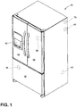
FIG. 1 is a perspective view of a French-door bottom-mount refrigeration appliance, according to one example; -
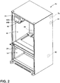
FIG. 2 is a perspective view of the refrigeration appliance having its doors removed, according to one example; -
FIG. 3 is a front elevation view of the refrigeration appliance having its refrigeration compartment doors open, according to one example; -
FIG. 4 is a perspective view of the refrigeration appliance having its doors in an open position, according to one example; and -
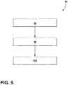
FIG. 5 is flow chart of a method of operating the refrigeration appliance, according to one example. - Referring now to
FIGS. 1-5 ,reference numeral 10 generally designates arefrigeration appliance 10 including afreezer compartment 14, arefrigeration compartment 18 and aince maker compartment 22. Theice maker compartment 22 may be positioned outside of thefreezer compartment 14. An icemaker supply duct 26 and an icemaker return duct 30 fluidly couple theice maker compartment 22 with thefreezer compartment 14. Apressure sensor 34 is positioned within thefreezer compartment 14. Thesensor 34 is configured to detect a pressure differential between thefreezer compartment 14 and an external environment (e.g., the atmosphere) to therefrigeration appliance 10. Afan 38 is positioned within the icemaker return duct 30. Thefan 38 is configured to be activated when the pressure within thefreezer compartment 14 is lower than the external environment (i.e., a negative pressure is sensed within the freezer compartment 14). Acontroller 40 is electrically coupled to thefan 38 and thesensor 34 for activating thefan 38. - Referring now to
FIGS. 1-3 , therefrigeration appliance 10 is depicted as a French-door bottom-mount refrigerator, but it will be understood that therefrigeration appliance 10 may be a side-by-side refrigerator, a bottom mount refrigerator and/or a top mount refrigerator. Therefrigeration appliance 10 includes therefrigeration compartment 18 and thefreezer compartment 14. Therefrigeration compartment 18 may be a fresh food compartment configured to store food stuffs and/or perishables at temperatures above freezing (e.g., maintained at about 3° C or about 4° C) for long time period. Thefreezer compartment 14 is maintained at a subzero temperature for long term storage of perishables in a frozen state. In general, therefrigeration compartment 18 may have an internal volume greater than thefreezer compartment 14. Therefrigeration appliance 10 includes anevaporator 42 which cools therefrigeration compartment 18 and thefreezer compartment 14. One ormore refrigeration doors 44 are provided for therefrigeration compartment 18 and afreezer door 48 is provided for thefreezer compartment 14. One of therefrigeration doors 44 may include anice dispenser 52, which may also include a water dispenser. - In the depicted example, the
ice maker compartment 22 is provided in therefrigeration compartment 18. More precisely, in the depicted example, theice maker compartment 22 is positioned in an upper corner of therefrigeration compartment 18, but it will be understood that theice maker compartment 22 may be positioned in other locations within therefrigeration compartment 18 without departing from the teachings provided herein. For example, theice maker compartment 22 may be positioned within therefrigeration doors 44 and/or thefreezer door 48. Theice maker compartment 22 may include an ice maker covering 60. The ice maker covering 60 may include afront cover 60A that is insulated to prevent the cold air of theice maker compartment 22 from passing into therefrigeration compartment 18. The ice maker covering 60 defines an opening 60B which mates with achute 64 of theice dispenser 52. A seal may be provided between the opening 60B and thechute 64 to prevent cold air from passing from theice maker compartment 22 to therefrigeration compartment 18. An ice making apparatus may be positioned within the ice maker covering 60. Theice maker compartment 22 may be configured to use cool air provided by the icemaker supply duct 26 to freeze water and dispense the ice through thechute 64. Theice maker compartment 22 is maintained at a temperature of 0° C or less in order to form ice, but may not be as cold as thefreezer compartment 14. The ice maker covering 60 may be integrally formed adjacent therefrigeration compartment 18 during a liner forming process. Alternatively, the ice maker covering 60 may be a separate component from the liner of therefrigeration compartment 18 and attached (e.g., by overhead rails, fasteners, etc.) to the liner. - Referring now to
FIGS. 3 and4 , the icemaker supply duct 26 extends between thefreezer compartment 14 and theice maker compartment 22. The icemaker supply duct 26 fluidly couples thefreezer compartment 14 and theice maker compartment 22. In other words, thesupply duct 26 allows chilled air to pass from thefreezer compartment 14 to theice maker compartment 22. Thesupply duct 26 has alower air inlet 26A within thefreezer compartment 14 and anupper outlet 26B connected to anice maker fan 70 mounted on the back wall of theice maker compartment 22. Theice maker fan 70 draws cold air from thefreezer compartment 14 and forces the cold air into theice maker compartment 22 to facilitate ice making. It will be understood that additionally or alternatively, theice maker fan 70 may be positioned at theinlet 26A, or anywhere along, thesupply duct 26. Theice maker fan 70 controls the air flow from thefreezer compartment 14 to theice maker compartment 22 and may be a variable speed fan. The icemaker supply duct 26 may be positioned within a rear wall of therefrigeration appliance 10, but may additionally or alternatively be positioned within side walls of therefrigeration appliance 10. - Similarly to the
supply duct 26, the icemaker return duct 30 may be positioned within a rear wall of therefrigeration appliance 10. Thereturn duct 30 may additionally or alternatively be positioned within side walls of therefrigeration appliance 10. The ice maker returnduct 30 fluidly couples thefreezer compartment 14 and theice maker compartment 22. In other words, thereturn duct 30 allows chilled air to pass from theice maker compartment 22 to thefreezer compartment 14. The ice maker returnair duct 30 includes anupper end 30A connected to theice maker compartment 22, and alower end 30B terminating within thefreezer compartment 14. - The
fan 38 is positioned within the ice maker returnduct 30. Thefan 38 may be positioned within theupper end 30A, thelower end 30B or anywhere along thereturn duct 30. Further, thefan 38 may be a fan assembly including a plurality of fans, positioned proximate one another, or spread across the ice maker returnduct 30. Thefan 38 may be configured to blow air from theice maker compartment 22 into thefreezer compartment 14. Further, due to a negative pressure generated by the activation of thefan 38, air from within therefrigeration compartment 18 may be sucked into theice maker compartment 22 and/or returnduct 30 such that air from therefrigeration compartment 18 is blown into thefreezer compartment 14. Thefan 38 may be pulse width modulated in order to adjust a fan speed of thefan 38. For example, the magnitude of the fan speed may be controlled by thecontroller 40 to increase or decrease the volume of air blown by thefan 38 into thefreezer compartment 14. - The
sensor 34 may be positioned within thefreezer compartment 14. In the depicted example, thesensor 34 is positioned on a side wall of thefreezer compartment 14, but may additionally or alternatively be positioned on a back wall, a top wall and/or a bottom wall of thefreezer compartment 14. Further, a plurality ofsensors 34 may be positioned throughout, or in a single location, of thefreezer compartment 14. Thesensor 34 may be a pressure sensor, humidity sensor, an airflow (e.g., mass flow) sensor and/or combinations thereof. Further, in examples where a plurality ofsensors 34 are utilized, eachsensor 34 may be different (e.g., onepressure sensor 34, onehumidity sensor 34, one air flow sensor 34). - The
pressure sensor 34 may be a gauge pressure sensor or a differential pressure sensor. The pressure sensor examples of thesensor 34 may be analog or digital. - The
sensor 34 is electrically coupled with thecontroller 40 and configured to communicate data to thecontroller 40 based on the pressure differential between thefreezer compartment 14 and the external environment. - In an example not part of the present invention, the
refrigeration appliance 10 may utilize a predetermined value of external environment pressure. The pressure differential may be calculated using the data provided by thesensor 34 and the predetermined value. The value may be based on manufacturer settings, user input settings, or calculated values. For example, a user or owner of therefrigeration appliance 10 may input an altitude and/or location (e.g., from which pressure may be looked up, preprogrammed, and/or determined) and thecontroller 40 may assign the predetermined value based on the input data from the user. Through comparison of the data from thesensor 34 and the predetermined value, a differential in the pressure may be determined. - The
controller 40 is configured to activate and/or deactivate thefan 38 based on the pressure differential detected by thepressure sensor 34. For example, if a pressure within thefreezer compartment 14 is lower than the external environment (i.e., a pressure differential exists), thecontroller 40 activates thefan 38 to blow air into thefreezer compartment 14. Specifically, if a negative pressure differential (i.e., the pressure within thefreezer compartment 14 is lower relative to the external environment) exists, thefan 38 is activated to blow air into thefreezer compartment 14. The fan speed of thefan 38, as controlled by thecontroller 40, may be based on the magnitude of the negative pressure differential sensed. For example, the greater the pressure differential (i.e., the greater the negative pressured sensed in the freezer compartment 14), the greater the fan speed. - Referring now to
FIG. 5 , depicted is anexemplary method 90 of operating therefrigeration appliance 10. Themethod 90 may begin with astep 94 of sensing a negative air pressure, relative to an atmospheric pressure, within thefreezer compartment 14. As explained above, thesensor 34 is a pressure sensor.
In an example not part of the present invention, thecontroller 40 may compare the data from thesensor 34 and anexternal sensor 78 to determine if a negative pressure differential exists. Thefan 38 may be configured to be inactive when the sensed pressure in thefreezer compartment 14 is equal to or greater than the external environment pressure. Next, step 98 of activating thefan 38 to blow air into thefreezer compartment 14 may be performed. Thecontroller 40 may control the fan speed based on the sensed magnitude of the pressure differential. Further, the fan speed may be adjusted while in use based on a magnitude of the pressure differential if it changes. In other words, the fan speed may be decreased or increased as the magnitude of pressure differential decreases or increases, respectively. Next, step 102 of deactivating thefan 38 may be performed. Thefan 38 may be deactivated once a sensed air pressure in the freezer compartment 14 (e.g., as sensed by the sensor 34) is equal to or greater than the atmospheric pressure (e.g., as sensed by the external sensor 78).
It will be understood that the pressure differential at which thecontroller 40 activates and deactivates thefan 38 may have to reach a predetermined threshold prior to activation and/or deactivation. For example, a predetermined threshold may be a 0.01%, 0.1%, 1%, 2%, 5% pressure differential to activate or deactivate thefan 38. Further, the predetermined thresholds for activation and deactivation may be different than one another. The sensed air pressure of thefreezer compartment 14 may be said to be about equal with the atmospheric pressure if a pressure differential between the two is less than about 10%. - Use of the present disclosure may offer a variety of advantages. First, use of the
fan 38 which is activated and deactivated based on sensed properties of therefrigeration appliance 10, may prevent unnecessary use of thefan 38. For example, by activating or running thefan 38 only when a sensed differential exists, therefrigeration appliance 10 may have a decreased noise and energy consumption. Second, use of thefan 38 within thereturn duct 30 reduces and/or eliminates the accumulation of frost and ice within thefreezer compartment 14. Third, the addition of thefan 38 to thereturn duct 30 may allow for a low manufacturing cost solution which may be implemented in a variety of refrigeration appliance styles. Fourth, the present disclosure is a robust solution to negative pressure generation as the pressure can be equalized regardless of the usage pattern, condition of gaskets around therefrigeration appliance 10, alignment of thedoors freezer door 48. For example, by reducing the magnitude of the pressure differential between thefreezer compartment 14 and the external environment, the force to open thefreezer door 48 may be reduced. Such a reduction of force may be advantageous in allowing therefrigeration appliance 10 to meet regulations regarding minimum pull force on thedoors freezer compartment 14. - It will be understood by one having ordinary skill in the art that construction of the described disclosure and other components is not limited to any specific material. Other exemplary embodiments of the disclosure disclosed herein may be formed from a wide variety of materials, unless described otherwise herein.
- For purposes of this disclosure, the term "coupled" (in all of its forms, couple, coupling, coupled, etc.) generally means the joining of two components (electrical or mechanical) directly or indirectly to one another. Such joining may be stationary in nature or movable in nature. Such joining may be achieved with the two components (electrical or mechanical) and any additional intermediate members being integrally formed as a single unitary body with one another or with the two components. Such joining may be permanent in nature or may be removable or releasable in nature unless otherwise stated.
Claims (10)
- A refrigeration appliance (10), comprising:a freezer compartment (14)a refrigeration compartment (18);an ice maker compartment (22) positioned within the refrigeration compartment (18);an ice maker return duct (30) fluidly coupling the ice maker compartment (22) and the freezer compartment (14);a pressure sensor (34) positioned within the freezer compartment (14) and configured to detect a pressure differential between the freezer compartment (14) and an external environment; anda fan (38) positioned within the ice maker return duct (30) and configured to be activated by a controller (40) electrically coupled to the fan (38) and the pressure sensor (34), when the pressure differential between the freezer compartment (14) and the external environment is smaller than zero, the fan (38) being configured to blow air from the ice maker compartment (22) and/ or from the refrigeration compartment (18) into the freezer compartment (14).
- The refrigeration appliance (10) of claim 1, wherein the fan (38) is pulse width modulated.
- The refrigeration appliance (10) of any of claims 1-2, wherein a magnitude of a fan speed of the fan (38) is based on a magnitude of the detected pressure differential between the freezer compartment (14) and an external environment.
- The refrigeration appliance (10) of any of claims 1-3, further comprising: an ice maker supply duct (26) fluidly coupling the freezer compartment (14) and the ice maker compartment (22).
- The refrigeration appliance (10) of any of claims 1-4, wherein the fan (38) is configured to be inactive when the detected pressure differential between the freezer compartment (14) and the external environment is equal to or greater than zero.
- Method of operating a refrigeration appliance (10) according to any of the claims 1-5, comprising the steps:sensing negative air pressure relative to an atmospheric pressure in a freezer compartment(14) of the refrigeration appliance (10);activating a fan (38) positioned in an ice maker return duct (30) of the refrigeration appliance (10) to blow air into the freezer compartment (14); anddeactivating the fan (38) when the detected pressure differential between the freezer compartment (14) and the external environment is equal to or greater than zero.
- The method of claim 6, further comprising the step of: adjusting a speed of the fan (38) based on the magnitude of the pressure differential between the freezer compartment and the external environment.
- The method of either of claims 6 and 7, further comprising the step of: blowing air from an ice maker compartment (22) or a refrigeration compartment (18) into the freezer compartment (14).
- The method of any of claims 6-8, wherein the step of deactivating the fan (38) is performed once the detected pressure differential between the freezer compartment (14) and the external environment is equal to zero.
- The method of any of claims 6-9, wherein the step of activating the fan (38) is performed such that a magnitude of a fan speed of the fan (38) is based on the magnitude of the detected pressure differential between the freezer compartment (14) and the external environment.
Applications Claiming Priority (1)
| Application Number | Priority Date | Filing Date | Title |
|---|---|---|---|
| US15/377,455 US10837694B2 (en) | 2016-12-13 | 2016-12-13 | Refrigeration appliance fan |
Publications (2)
| Publication Number | Publication Date |
|---|---|
| EP3336461A1 EP3336461A1 (en) | 2018-06-20 |
| EP3336461B1 true EP3336461B1 (en) | 2021-02-24 |
Family
ID=60673529
Family Applications (1)
| Application Number | Title | Priority Date | Filing Date |
|---|---|---|---|
| EP17207169.8A Not-in-force EP3336461B1 (en) | 2016-12-13 | 2017-12-13 | Refrigeration appliance fan |
Country Status (2)
| Country | Link |
|---|---|
| US (1) | US10837694B2 (en) |
| EP (1) | EP3336461B1 (en) |
Families Citing this family (8)
| Publication number | Priority date | Publication date | Assignee | Title |
|---|---|---|---|---|
| CN109373673B (en) * | 2018-11-06 | 2020-12-11 | 海尔智家股份有限公司 | refrigerator |
| CN109990546B (en) * | 2019-03-29 | 2021-04-09 | 长虹美菱股份有限公司 | A kind of refrigerator defrosting method and device |
| KR102896119B1 (en) * | 2019-07-09 | 2025-12-05 | 엘지전자 주식회사 | Vacuum adiabatic body and refrigerator |
| US20210262718A1 (en) * | 2020-02-25 | 2021-08-26 | Whirlpool Corporation | Refrigerator with duct system to provide cold air from a freezer evaporator to an ice maker |
| CN213273353U (en) * | 2020-09-10 | 2021-05-25 | 青岛海尔电冰箱有限公司 | refrigerator |
| KR20220166452A (en) * | 2021-06-10 | 2022-12-19 | 엘지전자 주식회사 | Refrigerator |
| JP2024093022A (en) * | 2022-12-27 | 2024-07-09 | 日立グローバルライフソリューションズ株式会社 | refrigerator |
| CN223975281U (en) | 2025-04-11 | 2026-03-06 | 深圳市维特世嘉科技有限公司 | Side heat dissipation refrigeration fan |
Family Cites Families (18)
| Publication number | Priority date | Publication date | Assignee | Title |
|---|---|---|---|---|
| SE467801B (en) | 1991-01-10 | 1992-09-14 | Electrolux Ab | FROZEN FURNITURE WITH DEVICE TO PREVENT FROZEN IMAGE |
| JP3229671B2 (en) | 1992-10-22 | 2001-11-19 | 三洋電機株式会社 | freezer |
| JPH08327215A (en) | 1995-05-30 | 1996-12-13 | Sanyo Electric Co Ltd | Deep freezer |
| US6176776B1 (en) | 1999-06-17 | 2001-01-23 | Kason Industries, Inc. | Pressure relief port |
| DE102005021592A1 (en) | 2005-05-10 | 2006-11-16 | BSH Bosch und Siemens Hausgeräte GmbH | Refrigeration device with door opening help |
| US7284390B2 (en) | 2005-05-18 | 2007-10-23 | Whirlpool Corporation | Refrigerator with intermediate temperature icemaking compartment |
| US7337620B2 (en) | 2005-05-18 | 2008-03-04 | Whirlpool Corporation | Insulated ice compartment for bottom mount refrigerator |
| CN101074828A (en) | 2006-05-15 | 2007-11-21 | 中国国际海运集装箱(集团)股份有限公司 | Ice maker for freezing container and its controlling method |
| DE202006013229U1 (en) | 2006-08-29 | 2006-10-26 | BSH Bosch und Siemens Hausgeräte GmbH | Cooling device e.g. refrigerator/freezer, has opening parallel to pressure balancing valve, where conductance of housing is smaller than that of valve in penetrable direction and larger than leakage conductance of valve in closing direction |
| DE202008000757U1 (en) | 2007-12-28 | 2009-04-30 | Liebherr-Hausgeräte Ochsenhausen GmbH | Fridge and / or freezer |
| CN105423682A (en) | 2008-09-30 | 2016-03-23 | 赛默飞世尔科技(阿什维尔)有限责任公司 | Frost reduction by active circulation |
| US20100077778A1 (en) | 2008-10-01 | 2010-04-01 | Kim Brian S | Pressure Equalizing Device for Refrigerator |
| WO2014022364A1 (en) | 2012-07-31 | 2014-02-06 | Global Cooling, Inc. | Passive vacuum relief valve |
| KR101571111B1 (en) * | 2013-05-09 | 2015-11-23 | 심기섭 | Temperature and air pressure balanced ventilation unit and storage system using the ventilation unit |
| DE102014203683A1 (en) | 2014-02-28 | 2015-09-03 | BSH Hausgeräte GmbH | Home appliance with a door opening aid |
| US10501972B2 (en) * | 2015-03-31 | 2019-12-10 | Follett Corporation | Refrigeration system and control system therefor |
| KR101754359B1 (en) * | 2015-06-17 | 2017-07-19 | 동부대우전자 주식회사 | Cold air circulation structure of refrigerator and control method therefor |
| EP3147603A1 (en) * | 2015-09-28 | 2017-03-29 | Whirlpool Corporation | Refrigerator with a device for an easy opening of the door |
-
2016
- 2016-12-13 US US15/377,455 patent/US10837694B2/en active Active
-
2017
- 2017-12-13 EP EP17207169.8A patent/EP3336461B1/en not_active Not-in-force
Non-Patent Citations (1)
| Title |
|---|
| None * |
Also Published As
| Publication number | Publication date |
|---|---|
| US20180164020A1 (en) | 2018-06-14 |
| US10837694B2 (en) | 2020-11-17 |
| EP3336461A1 (en) | 2018-06-20 |
Similar Documents
| Publication | Publication Date | Title |
|---|---|---|
| US10837694B2 (en) | Refrigeration appliance fan | |
| US12181201B2 (en) | Refrigeration appliance fan | |
| CN102353203B (en) | Refrigerator | |
| CN106679265B (en) | A refrigerator and its control method | |
| JP6254385B2 (en) | refrigerator | |
| US20210262718A1 (en) | Refrigerator with duct system to provide cold air from a freezer evaporator to an ice maker | |
| WO2015035886A1 (en) | Refrigerator | |
| US20060156755A1 (en) | Methods and apparatus for operating a refrigerator | |
| US7665320B2 (en) | Damper assembly and methods for a refrigeration device | |
| KR100443317B1 (en) | Refrigeration showcase | |
| JP2015038409A (en) | refrigerator | |
| JP2013224777A (en) | Refrigerator | |
| KR20110118196A (en) | Showcase to prevent dew condensation on the door | |
| JP6266140B2 (en) | refrigerator | |
| CN111288712A (en) | Refrigerator with a door | |
| US20240183600A1 (en) | Airflow method and airflow system for temperature control in a refrigeration appliance | |
| CN111623578A (en) | Hydrophobic coating on evaporator to promote food preservation | |
| JP2013061082A (en) | Refrigerator | |
| KR200283650Y1 (en) | Refrigeration showcase | |
| KR20060110150A (en) | Refrigerator | |
| JP2008057919A (en) | Refrigerator | |
| KR20070016319A (en) | Vegetable room independent temperature control system of refrigerator | |
| US20240142159A1 (en) | Airflow system and method for temperature control in integrated compartments in a refrigeration appliance | |
| KR100823915B1 (en) | Fresh air supply device of freezer | |
| KR20070016320A (en) | Refrigerator with independent temperature control |
Legal Events
| Date | Code | Title | Description |
|---|---|---|---|
| PUAI | Public reference made under article 153(3) epc to a published international application that has entered the european phase |
Free format text: ORIGINAL CODE: 0009012 |
|
| STAA | Information on the status of an ep patent application or granted ep patent |
Free format text: STATUS: THE APPLICATION HAS BEEN PUBLISHED |
|
| AK | Designated contracting states |
Kind code of ref document: A1 Designated state(s): AL AT BE BG CH CY CZ DE DK EE ES FI FR GB GR HR HU IE IS IT LI LT LU LV MC MK MT NL NO PL PT RO RS SE SI SK SM TR |
|
| AX | Request for extension of the european patent |
Extension state: BA ME |
|
| STAA | Information on the status of an ep patent application or granted ep patent |
Free format text: STATUS: REQUEST FOR EXAMINATION WAS MADE |
|
| 17P | Request for examination filed |
Effective date: 20181127 |
|
| RBV | Designated contracting states (corrected) |
Designated state(s): AL AT BE BG CH CY CZ DE DK EE ES FI FR GB GR HR HU IE IS IT LI LT LU LV MC MK MT NL NO PL PT RO RS SE SI SK SM TR |
|
| GRAP | Despatch of communication of intention to grant a patent |
Free format text: ORIGINAL CODE: EPIDOSNIGR1 |
|
| STAA | Information on the status of an ep patent application or granted ep patent |
Free format text: STATUS: GRANT OF PATENT IS INTENDED |
|
| INTG | Intention to grant announced |
Effective date: 20201104 |
|
| GRAS | Grant fee paid |
Free format text: ORIGINAL CODE: EPIDOSNIGR3 |
|
| GRAA | (expected) grant |
Free format text: ORIGINAL CODE: 0009210 |
|
| STAA | Information on the status of an ep patent application or granted ep patent |
Free format text: STATUS: THE PATENT HAS BEEN GRANTED |
|
| AK | Designated contracting states |
Kind code of ref document: B1 Designated state(s): AL AT BE BG CH CY CZ DE DK EE ES FI FR GB GR HR HU IE IS IT LI LT LU LV MC MK MT NL NO PL PT RO RS SE SI SK SM TR |
|
| REG | Reference to a national code |
Ref country code: CH Ref legal event code: EP |
|
| REG | Reference to a national code |
Ref country code: AT Ref legal event code: REF Ref document number: 1364984 Country of ref document: AT Kind code of ref document: T Effective date: 20210315 |
|
| REG | Reference to a national code |
Ref country code: IE Ref legal event code: FG4D |
|
| REG | Reference to a national code |
Ref country code: DE Ref legal event code: R096 Ref document number: 602017033153 Country of ref document: DE |
|
| REG | Reference to a national code |
Ref country code: LT Ref legal event code: MG9D |
|
| REG | Reference to a national code |
Ref country code: NL Ref legal event code: MP Effective date: 20210224 |
|
| PG25 | Lapsed in a contracting state [announced via postgrant information from national office to epo] |
Ref country code: HR Free format text: LAPSE BECAUSE OF FAILURE TO SUBMIT A TRANSLATION OF THE DESCRIPTION OR TO PAY THE FEE WITHIN THE PRESCRIBED TIME-LIMIT Effective date: 20210224 Ref country code: FI Free format text: LAPSE BECAUSE OF FAILURE TO SUBMIT A TRANSLATION OF THE DESCRIPTION OR TO PAY THE FEE WITHIN THE PRESCRIBED TIME-LIMIT Effective date: 20210224 Ref country code: GR Free format text: LAPSE BECAUSE OF FAILURE TO SUBMIT A TRANSLATION OF THE DESCRIPTION OR TO PAY THE FEE WITHIN THE PRESCRIBED TIME-LIMIT Effective date: 20210525 Ref country code: PT Free format text: LAPSE BECAUSE OF FAILURE TO SUBMIT A TRANSLATION OF THE DESCRIPTION OR TO PAY THE FEE WITHIN THE PRESCRIBED TIME-LIMIT Effective date: 20210624 Ref country code: NO Free format text: LAPSE BECAUSE OF FAILURE TO SUBMIT A TRANSLATION OF THE DESCRIPTION OR TO PAY THE FEE WITHIN THE PRESCRIBED TIME-LIMIT Effective date: 20210524 Ref country code: BG Free format text: LAPSE BECAUSE OF FAILURE TO SUBMIT A TRANSLATION OF THE DESCRIPTION OR TO PAY THE FEE WITHIN THE PRESCRIBED TIME-LIMIT Effective date: 20210524 Ref country code: LT Free format text: LAPSE BECAUSE OF FAILURE TO SUBMIT A TRANSLATION OF THE DESCRIPTION OR TO PAY THE FEE WITHIN THE PRESCRIBED TIME-LIMIT Effective date: 20210224 |
|
| REG | Reference to a national code |
Ref country code: AT Ref legal event code: MK05 Ref document number: 1364984 Country of ref document: AT Kind code of ref document: T Effective date: 20210224 |
|
| PG25 | Lapsed in a contracting state [announced via postgrant information from national office to epo] |
Ref country code: SE Free format text: LAPSE BECAUSE OF FAILURE TO SUBMIT A TRANSLATION OF THE DESCRIPTION OR TO PAY THE FEE WITHIN THE PRESCRIBED TIME-LIMIT Effective date: 20210224 Ref country code: RS Free format text: LAPSE BECAUSE OF FAILURE TO SUBMIT A TRANSLATION OF THE DESCRIPTION OR TO PAY THE FEE WITHIN THE PRESCRIBED TIME-LIMIT Effective date: 20210224 Ref country code: LV Free format text: LAPSE BECAUSE OF FAILURE TO SUBMIT A TRANSLATION OF THE DESCRIPTION OR TO PAY THE FEE WITHIN THE PRESCRIBED TIME-LIMIT Effective date: 20210224 Ref country code: NL Free format text: LAPSE BECAUSE OF FAILURE TO SUBMIT A TRANSLATION OF THE DESCRIPTION OR TO PAY THE FEE WITHIN THE PRESCRIBED TIME-LIMIT Effective date: 20210224 Ref country code: PL Free format text: LAPSE BECAUSE OF FAILURE TO SUBMIT A TRANSLATION OF THE DESCRIPTION OR TO PAY THE FEE WITHIN THE PRESCRIBED TIME-LIMIT Effective date: 20210224 |
|
| PG25 | Lapsed in a contracting state [announced via postgrant information from national office to epo] |
Ref country code: IS Free format text: LAPSE BECAUSE OF FAILURE TO SUBMIT A TRANSLATION OF THE DESCRIPTION OR TO PAY THE FEE WITHIN THE PRESCRIBED TIME-LIMIT Effective date: 20210624 |
|
| PG25 | Lapsed in a contracting state [announced via postgrant information from national office to epo] |
Ref country code: SM Free format text: LAPSE BECAUSE OF FAILURE TO SUBMIT A TRANSLATION OF THE DESCRIPTION OR TO PAY THE FEE WITHIN THE PRESCRIBED TIME-LIMIT Effective date: 20210224 Ref country code: AT Free format text: LAPSE BECAUSE OF FAILURE TO SUBMIT A TRANSLATION OF THE DESCRIPTION OR TO PAY THE FEE WITHIN THE PRESCRIBED TIME-LIMIT Effective date: 20210224 Ref country code: EE Free format text: LAPSE BECAUSE OF FAILURE TO SUBMIT A TRANSLATION OF THE DESCRIPTION OR TO PAY THE FEE WITHIN THE PRESCRIBED TIME-LIMIT Effective date: 20210224 Ref country code: CZ Free format text: LAPSE BECAUSE OF FAILURE TO SUBMIT A TRANSLATION OF THE DESCRIPTION OR TO PAY THE FEE WITHIN THE PRESCRIBED TIME-LIMIT Effective date: 20210224 |
|
| REG | Reference to a national code |
Ref country code: DE Ref legal event code: R097 Ref document number: 602017033153 Country of ref document: DE |
|
| PG25 | Lapsed in a contracting state [announced via postgrant information from national office to epo] |
Ref country code: RO Free format text: LAPSE BECAUSE OF FAILURE TO SUBMIT A TRANSLATION OF THE DESCRIPTION OR TO PAY THE FEE WITHIN THE PRESCRIBED TIME-LIMIT Effective date: 20210224 Ref country code: SK Free format text: LAPSE BECAUSE OF FAILURE TO SUBMIT A TRANSLATION OF THE DESCRIPTION OR TO PAY THE FEE WITHIN THE PRESCRIBED TIME-LIMIT Effective date: 20210224 Ref country code: DK Free format text: LAPSE BECAUSE OF FAILURE TO SUBMIT A TRANSLATION OF THE DESCRIPTION OR TO PAY THE FEE WITHIN THE PRESCRIBED TIME-LIMIT Effective date: 20210224 |
|
| PLBE | No opposition filed within time limit |
Free format text: ORIGINAL CODE: 0009261 |
|
| STAA | Information on the status of an ep patent application or granted ep patent |
Free format text: STATUS: NO OPPOSITION FILED WITHIN TIME LIMIT |
|
| PG25 | Lapsed in a contracting state [announced via postgrant information from national office to epo] |
Ref country code: ES Free format text: LAPSE BECAUSE OF FAILURE TO SUBMIT A TRANSLATION OF THE DESCRIPTION OR TO PAY THE FEE WITHIN THE PRESCRIBED TIME-LIMIT Effective date: 20210224 Ref country code: AL Free format text: LAPSE BECAUSE OF FAILURE TO SUBMIT A TRANSLATION OF THE DESCRIPTION OR TO PAY THE FEE WITHIN THE PRESCRIBED TIME-LIMIT Effective date: 20210224 |
|
| 26N | No opposition filed |
Effective date: 20211125 |
|
| PG25 | Lapsed in a contracting state [announced via postgrant information from national office to epo] |
Ref country code: SI Free format text: LAPSE BECAUSE OF FAILURE TO SUBMIT A TRANSLATION OF THE DESCRIPTION OR TO PAY THE FEE WITHIN THE PRESCRIBED TIME-LIMIT Effective date: 20210224 |
|
| PG25 | Lapsed in a contracting state [announced via postgrant information from national office to epo] |
Ref country code: IS Free format text: LAPSE BECAUSE OF FAILURE TO SUBMIT A TRANSLATION OF THE DESCRIPTION OR TO PAY THE FEE WITHIN THE PRESCRIBED TIME-LIMIT Effective date: 20210624 |
|
| PG25 | Lapsed in a contracting state [announced via postgrant information from national office to epo] |
Ref country code: MC Free format text: LAPSE BECAUSE OF FAILURE TO SUBMIT A TRANSLATION OF THE DESCRIPTION OR TO PAY THE FEE WITHIN THE PRESCRIBED TIME-LIMIT Effective date: 20210224 |
|
| REG | Reference to a national code |
Ref country code: CH Ref legal event code: PL |
|
| REG | Reference to a national code |
Ref country code: BE Ref legal event code: MM Effective date: 20211231 |
|
| PG25 | Lapsed in a contracting state [announced via postgrant information from national office to epo] |
Ref country code: LU Free format text: LAPSE BECAUSE OF NON-PAYMENT OF DUE FEES Effective date: 20211213 Ref country code: IE Free format text: LAPSE BECAUSE OF NON-PAYMENT OF DUE FEES Effective date: 20211213 |
|
| PG25 | Lapsed in a contracting state [announced via postgrant information from national office to epo] |
Ref country code: BE Free format text: LAPSE BECAUSE OF NON-PAYMENT OF DUE FEES Effective date: 20211231 |
|
| PG25 | Lapsed in a contracting state [announced via postgrant information from national office to epo] |
Ref country code: LI Free format text: LAPSE BECAUSE OF NON-PAYMENT OF DUE FEES Effective date: 20211231 Ref country code: CH Free format text: LAPSE BECAUSE OF NON-PAYMENT OF DUE FEES Effective date: 20211231 |
|
| PGFP | Annual fee paid to national office [announced via postgrant information from national office to epo] |
Ref country code: FR Payment date: 20221010 Year of fee payment: 6 |
|
| PGFP | Annual fee paid to national office [announced via postgrant information from national office to epo] |
Ref country code: IT Payment date: 20221111 Year of fee payment: 6 Ref country code: GB Payment date: 20221020 Year of fee payment: 6 Ref country code: DE Payment date: 20221018 Year of fee payment: 6 |
|
| PG25 | Lapsed in a contracting state [announced via postgrant information from national office to epo] |
Ref country code: HU Free format text: LAPSE BECAUSE OF FAILURE TO SUBMIT A TRANSLATION OF THE DESCRIPTION OR TO PAY THE FEE WITHIN THE PRESCRIBED TIME-LIMIT; INVALID AB INITIO Effective date: 20171213 |
|
| P01 | Opt-out of the competence of the unified patent court (upc) registered |
Effective date: 20230522 |
|
| PG25 | Lapsed in a contracting state [announced via postgrant information from national office to epo] |
Ref country code: CY Free format text: LAPSE BECAUSE OF FAILURE TO SUBMIT A TRANSLATION OF THE DESCRIPTION OR TO PAY THE FEE WITHIN THE PRESCRIBED TIME-LIMIT Effective date: 20210224 |
|
| PG25 | Lapsed in a contracting state [announced via postgrant information from national office to epo] |
Ref country code: MK Free format text: LAPSE BECAUSE OF FAILURE TO SUBMIT A TRANSLATION OF THE DESCRIPTION OR TO PAY THE FEE WITHIN THE PRESCRIBED TIME-LIMIT Effective date: 20210224 |
|
| PG25 | Lapsed in a contracting state [announced via postgrant information from national office to epo] |
Ref country code: TR Free format text: LAPSE BECAUSE OF FAILURE TO SUBMIT A TRANSLATION OF THE DESCRIPTION OR TO PAY THE FEE WITHIN THE PRESCRIBED TIME-LIMIT Effective date: 20210224 |
|
| REG | Reference to a national code |
Ref country code: DE Ref legal event code: R119 Ref document number: 602017033153 Country of ref document: DE |
|
| GBPC | Gb: european patent ceased through non-payment of renewal fee |
Effective date: 20231213 |
|
| PG25 | Lapsed in a contracting state [announced via postgrant information from national office to epo] |
Ref country code: MT Free format text: LAPSE BECAUSE OF FAILURE TO SUBMIT A TRANSLATION OF THE DESCRIPTION OR TO PAY THE FEE WITHIN THE PRESCRIBED TIME-LIMIT Effective date: 20210224 |
|
| PG25 | Lapsed in a contracting state [announced via postgrant information from national office to epo] |
Ref country code: DE Free format text: LAPSE BECAUSE OF NON-PAYMENT OF DUE FEES Effective date: 20240702 |
|
| PG25 | Lapsed in a contracting state [announced via postgrant information from national office to epo] |
Ref country code: GB Free format text: LAPSE BECAUSE OF NON-PAYMENT OF DUE FEES Effective date: 20231213 |
|
| PG25 | Lapsed in a contracting state [announced via postgrant information from national office to epo] |
Ref country code: FR Free format text: LAPSE BECAUSE OF NON-PAYMENT OF DUE FEES Effective date: 20231231 |
|
| PG25 | Lapsed in a contracting state [announced via postgrant information from national office to epo] |
Ref country code: GB Free format text: LAPSE BECAUSE OF NON-PAYMENT OF DUE FEES Effective date: 20231213 Ref country code: FR Free format text: LAPSE BECAUSE OF NON-PAYMENT OF DUE FEES Effective date: 20231231 Ref country code: DE Free format text: LAPSE BECAUSE OF NON-PAYMENT OF DUE FEES Effective date: 20240702 |
|
| PG25 | Lapsed in a contracting state [announced via postgrant information from national office to epo] |
Ref country code: IT Free format text: LAPSE BECAUSE OF NON-PAYMENT OF DUE FEES Effective date: 20231213 |