EP3336409A1 - System for measuring high pressure of in-tank regulator - Google Patents
System for measuring high pressure of in-tank regulator Download PDFInfo
- Publication number
- EP3336409A1 EP3336409A1 EP17192334.5A EP17192334A EP3336409A1 EP 3336409 A1 EP3336409 A1 EP 3336409A1 EP 17192334 A EP17192334 A EP 17192334A EP 3336409 A1 EP3336409 A1 EP 3336409A1
- Authority
- EP
- European Patent Office
- Prior art keywords
- flow path
- direct
- pipe flow
- pressure
- pressure sensor
- Prior art date
- Legal status (The legal status is an assumption and is not a legal conclusion. Google has not performed a legal analysis and makes no representation as to the accuracy of the status listed.)
- Granted
Links
- 210000001747 pupil Anatomy 0.000 claims description 9
- 230000007423 decrease Effects 0.000 claims description 2
- 210000000887 face Anatomy 0.000 claims 1
- 239000001257 hydrogen Substances 0.000 description 45
- 229910052739 hydrogen Inorganic materials 0.000 description 45
- UFHFLCQGNIYNRP-UHFFFAOYSA-N Hydrogen Chemical compound [H][H] UFHFLCQGNIYNRP-UHFFFAOYSA-N 0.000 description 44
- 239000000446 fuel Substances 0.000 description 44
- 239000007789 gas Substances 0.000 description 10
- 238000000034 method Methods 0.000 description 9
- 238000010586 diagram Methods 0.000 description 8
- 238000007789 sealing Methods 0.000 description 7
- 230000008569 process Effects 0.000 description 5
- 230000002159 abnormal effect Effects 0.000 description 4
- 230000006835 compression Effects 0.000 description 4
- 238000007906 compression Methods 0.000 description 4
- 238000003780 insertion Methods 0.000 description 4
- 230000037431 insertion Effects 0.000 description 4
- 238000004891 communication Methods 0.000 description 3
- 230000010485 coping Effects 0.000 description 3
- QVGXLLKOCUKJST-UHFFFAOYSA-N atomic oxygen Chemical compound [O] QVGXLLKOCUKJST-UHFFFAOYSA-N 0.000 description 2
- 230000000694 effects Effects 0.000 description 2
- 238000003487 electrochemical reaction Methods 0.000 description 2
- 238000012986 modification Methods 0.000 description 2
- 230000004048 modification Effects 0.000 description 2
- 239000007800 oxidant agent Substances 0.000 description 2
- 230000001590 oxidative effect Effects 0.000 description 2
- 239000001301 oxygen Substances 0.000 description 2
- 229910052760 oxygen Inorganic materials 0.000 description 2
- 230000008859 change Effects 0.000 description 1
- 238000006243 chemical reaction Methods 0.000 description 1
- 239000000470 constituent Substances 0.000 description 1
- 238000001816 cooling Methods 0.000 description 1
- 238000012217 deletion Methods 0.000 description 1
- 230000037430 deletion Effects 0.000 description 1
- 238000013461 design Methods 0.000 description 1
- 238000004880 explosion Methods 0.000 description 1
- 239000012530 fluid Substances 0.000 description 1
- 150000002431 hydrogen Chemical class 0.000 description 1
- 230000000149 penetrating effect Effects 0.000 description 1
- 239000003208 petroleum Substances 0.000 description 1
- 230000008439 repair process Effects 0.000 description 1
- XLYOFNOQVPJJNP-UHFFFAOYSA-N water Substances O XLYOFNOQVPJJNP-UHFFFAOYSA-N 0.000 description 1
Images


Classifications
-
- H—ELECTRICITY
- H01—ELECTRIC ELEMENTS
- H01M—PROCESSES OR MEANS, e.g. BATTERIES, FOR THE DIRECT CONVERSION OF CHEMICAL ENERGY INTO ELECTRICAL ENERGY
- H01M8/00—Fuel cells; Manufacture thereof
- H01M8/04—Auxiliary arrangements, e.g. for control of pressure or for circulation of fluids
- H01M8/04082—Arrangements for control of reactant parameters, e.g. pressure or concentration
- H01M8/04089—Arrangements for control of reactant parameters, e.g. pressure or concentration of gaseous reactants
- H01M8/04104—Regulation of differential pressures
-
- F—MECHANICAL ENGINEERING; LIGHTING; HEATING; WEAPONS; BLASTING
- F17—STORING OR DISTRIBUTING GASES OR LIQUIDS
- F17C—VESSELS FOR CONTAINING OR STORING COMPRESSED, LIQUEFIED OR SOLIDIFIED GASES; FIXED-CAPACITY GAS-HOLDERS; FILLING VESSELS WITH, OR DISCHARGING FROM VESSELS, COMPRESSED, LIQUEFIED, OR SOLIDIFIED GASES
- F17C13/00—Details of vessels or of the filling or discharging of vessels
- F17C13/02—Special adaptations of indicating, measuring, or monitoring equipment
- F17C13/025—Special adaptations of indicating, measuring, or monitoring equipment having the pressure as the parameter
-
- B—PERFORMING OPERATIONS; TRANSPORTING
- B60—VEHICLES IN GENERAL
- B60K—ARRANGEMENT OR MOUNTING OF PROPULSION UNITS OR OF TRANSMISSIONS IN VEHICLES; ARRANGEMENT OR MOUNTING OF PLURAL DIVERSE PRIME-MOVERS IN VEHICLES; AUXILIARY DRIVES FOR VEHICLES; INSTRUMENTATION OR DASHBOARDS FOR VEHICLES; ARRANGEMENTS IN CONNECTION WITH COOLING, AIR INTAKE, GAS EXHAUST OR FUEL SUPPLY OF PROPULSION UNITS IN VEHICLES
- B60K15/00—Arrangement in connection with fuel supply of combustion engines or other fuel consuming energy converters, e.g. fuel cells; Mounting or construction of fuel tanks
- B60K15/03—Fuel tanks
- B60K15/06—Fuel tanks characterised by fuel reserve systems
-
- F—MECHANICAL ENGINEERING; LIGHTING; HEATING; WEAPONS; BLASTING
- F17—STORING OR DISTRIBUTING GASES OR LIQUIDS
- F17C—VESSELS FOR CONTAINING OR STORING COMPRESSED, LIQUEFIED OR SOLIDIFIED GASES; FIXED-CAPACITY GAS-HOLDERS; FILLING VESSELS WITH, OR DISCHARGING FROM VESSELS, COMPRESSED, LIQUEFIED, OR SOLIDIFIED GASES
- F17C13/00—Details of vessels or of the filling or discharging of vessels
- F17C13/04—Arrangement or mounting of valves
-
- F—MECHANICAL ENGINEERING; LIGHTING; HEATING; WEAPONS; BLASTING
- F17—STORING OR DISTRIBUTING GASES OR LIQUIDS
- F17C—VESSELS FOR CONTAINING OR STORING COMPRESSED, LIQUEFIED OR SOLIDIFIED GASES; FIXED-CAPACITY GAS-HOLDERS; FILLING VESSELS WITH, OR DISCHARGING FROM VESSELS, COMPRESSED, LIQUEFIED, OR SOLIDIFIED GASES
- F17C5/00—Methods or apparatus for filling containers with liquefied, solidified, or compressed gases under pressures
- F17C5/02—Methods or apparatus for filling containers with liquefied, solidified, or compressed gases under pressures for filling with liquefied gases
-
- F—MECHANICAL ENGINEERING; LIGHTING; HEATING; WEAPONS; BLASTING
- F17—STORING OR DISTRIBUTING GASES OR LIQUIDS
- F17C—VESSELS FOR CONTAINING OR STORING COMPRESSED, LIQUEFIED OR SOLIDIFIED GASES; FIXED-CAPACITY GAS-HOLDERS; FILLING VESSELS WITH, OR DISCHARGING FROM VESSELS, COMPRESSED, LIQUEFIED, OR SOLIDIFIED GASES
- F17C7/00—Methods or apparatus for discharging liquefied, solidified, or compressed gases from pressure vessels, not covered by another subclass
- F17C7/02—Discharging liquefied gases
-
- B—PERFORMING OPERATIONS; TRANSPORTING
- B60—VEHICLES IN GENERAL
- B60K—ARRANGEMENT OR MOUNTING OF PROPULSION UNITS OR OF TRANSMISSIONS IN VEHICLES; ARRANGEMENT OR MOUNTING OF PLURAL DIVERSE PRIME-MOVERS IN VEHICLES; AUXILIARY DRIVES FOR VEHICLES; INSTRUMENTATION OR DASHBOARDS FOR VEHICLES; ARRANGEMENTS IN CONNECTION WITH COOLING, AIR INTAKE, GAS EXHAUST OR FUEL SUPPLY OF PROPULSION UNITS IN VEHICLES
- B60K15/00—Arrangement in connection with fuel supply of combustion engines or other fuel consuming energy converters, e.g. fuel cells; Mounting or construction of fuel tanks
- B60K15/03—Fuel tanks
- B60K2015/0321—Fuel tanks characterised by special sensors, the mounting thereof
-
- B—PERFORMING OPERATIONS; TRANSPORTING
- B60—VEHICLES IN GENERAL
- B60K—ARRANGEMENT OR MOUNTING OF PROPULSION UNITS OR OF TRANSMISSIONS IN VEHICLES; ARRANGEMENT OR MOUNTING OF PLURAL DIVERSE PRIME-MOVERS IN VEHICLES; AUXILIARY DRIVES FOR VEHICLES; INSTRUMENTATION OR DASHBOARDS FOR VEHICLES; ARRANGEMENTS IN CONNECTION WITH COOLING, AIR INTAKE, GAS EXHAUST OR FUEL SUPPLY OF PROPULSION UNITS IN VEHICLES
- B60K15/00—Arrangement in connection with fuel supply of combustion engines or other fuel consuming energy converters, e.g. fuel cells; Mounting or construction of fuel tanks
- B60K15/03—Fuel tanks
- B60K2015/03328—Arrangements or special measures related to fuel tanks or fuel handling
- B60K2015/03447—Arrangements or special measures related to fuel tanks or fuel handling for improving the sealing
-
- B—PERFORMING OPERATIONS; TRANSPORTING
- B60—VEHICLES IN GENERAL
- B60Y—INDEXING SCHEME RELATING TO ASPECTS CROSS-CUTTING VEHICLE TECHNOLOGY
- B60Y2400/00—Special features of vehicle units
- B60Y2400/30—Sensors
- B60Y2400/306—Pressure sensors
-
- F—MECHANICAL ENGINEERING; LIGHTING; HEATING; WEAPONS; BLASTING
- F17—STORING OR DISTRIBUTING GASES OR LIQUIDS
- F17C—VESSELS FOR CONTAINING OR STORING COMPRESSED, LIQUEFIED OR SOLIDIFIED GASES; FIXED-CAPACITY GAS-HOLDERS; FILLING VESSELS WITH, OR DISCHARGING FROM VESSELS, COMPRESSED, LIQUEFIED, OR SOLIDIFIED GASES
- F17C2205/00—Vessel construction, in particular mounting arrangements, attachments or identifications means
- F17C2205/03—Fluid connections, filters, valves, closure means or other attachments
- F17C2205/0302—Fittings, valves, filters, or components in connection with the gas storage device
- F17C2205/0323—Valves
- F17C2205/0329—Valves manually actuated
-
- F—MECHANICAL ENGINEERING; LIGHTING; HEATING; WEAPONS; BLASTING
- F17—STORING OR DISTRIBUTING GASES OR LIQUIDS
- F17C—VESSELS FOR CONTAINING OR STORING COMPRESSED, LIQUEFIED OR SOLIDIFIED GASES; FIXED-CAPACITY GAS-HOLDERS; FILLING VESSELS WITH, OR DISCHARGING FROM VESSELS, COMPRESSED, LIQUEFIED, OR SOLIDIFIED GASES
- F17C2205/00—Vessel construction, in particular mounting arrangements, attachments or identifications means
- F17C2205/03—Fluid connections, filters, valves, closure means or other attachments
- F17C2205/0302—Fittings, valves, filters, or components in connection with the gas storage device
- F17C2205/0323—Valves
- F17C2205/0335—Check-valves or non-return valves
-
- F—MECHANICAL ENGINEERING; LIGHTING; HEATING; WEAPONS; BLASTING
- F17—STORING OR DISTRIBUTING GASES OR LIQUIDS
- F17C—VESSELS FOR CONTAINING OR STORING COMPRESSED, LIQUEFIED OR SOLIDIFIED GASES; FIXED-CAPACITY GAS-HOLDERS; FILLING VESSELS WITH, OR DISCHARGING FROM VESSELS, COMPRESSED, LIQUEFIED, OR SOLIDIFIED GASES
- F17C2205/00—Vessel construction, in particular mounting arrangements, attachments or identifications means
- F17C2205/03—Fluid connections, filters, valves, closure means or other attachments
- F17C2205/0302—Fittings, valves, filters, or components in connection with the gas storage device
- F17C2205/0338—Pressure regulators
-
- F—MECHANICAL ENGINEERING; LIGHTING; HEATING; WEAPONS; BLASTING
- F17—STORING OR DISTRIBUTING GASES OR LIQUIDS
- F17C—VESSELS FOR CONTAINING OR STORING COMPRESSED, LIQUEFIED OR SOLIDIFIED GASES; FIXED-CAPACITY GAS-HOLDERS; FILLING VESSELS WITH, OR DISCHARGING FROM VESSELS, COMPRESSED, LIQUEFIED, OR SOLIDIFIED GASES
- F17C2205/00—Vessel construction, in particular mounting arrangements, attachments or identifications means
- F17C2205/03—Fluid connections, filters, valves, closure means or other attachments
- F17C2205/0302—Fittings, valves, filters, or components in connection with the gas storage device
- F17C2205/0341—Filters
-
- F—MECHANICAL ENGINEERING; LIGHTING; HEATING; WEAPONS; BLASTING
- F17—STORING OR DISTRIBUTING GASES OR LIQUIDS
- F17C—VESSELS FOR CONTAINING OR STORING COMPRESSED, LIQUEFIED OR SOLIDIFIED GASES; FIXED-CAPACITY GAS-HOLDERS; FILLING VESSELS WITH, OR DISCHARGING FROM VESSELS, COMPRESSED, LIQUEFIED, OR SOLIDIFIED GASES
- F17C2205/00—Vessel construction, in particular mounting arrangements, attachments or identifications means
- F17C2205/03—Fluid connections, filters, valves, closure means or other attachments
- F17C2205/0302—Fittings, valves, filters, or components in connection with the gas storage device
- F17C2205/0382—Constructional details of valves, regulators
- F17C2205/0385—Constructional details of valves, regulators in blocks or units
-
- F—MECHANICAL ENGINEERING; LIGHTING; HEATING; WEAPONS; BLASTING
- F17—STORING OR DISTRIBUTING GASES OR LIQUIDS
- F17C—VESSELS FOR CONTAINING OR STORING COMPRESSED, LIQUEFIED OR SOLIDIFIED GASES; FIXED-CAPACITY GAS-HOLDERS; FILLING VESSELS WITH, OR DISCHARGING FROM VESSELS, COMPRESSED, LIQUEFIED, OR SOLIDIFIED GASES
- F17C2205/00—Vessel construction, in particular mounting arrangements, attachments or identifications means
- F17C2205/03—Fluid connections, filters, valves, closure means or other attachments
- F17C2205/0388—Arrangement of valves, regulators, filters
- F17C2205/0394—Arrangement of valves, regulators, filters in direct contact with the pressure vessel
-
- F—MECHANICAL ENGINEERING; LIGHTING; HEATING; WEAPONS; BLASTING
- F17—STORING OR DISTRIBUTING GASES OR LIQUIDS
- F17C—VESSELS FOR CONTAINING OR STORING COMPRESSED, LIQUEFIED OR SOLIDIFIED GASES; FIXED-CAPACITY GAS-HOLDERS; FILLING VESSELS WITH, OR DISCHARGING FROM VESSELS, COMPRESSED, LIQUEFIED, OR SOLIDIFIED GASES
- F17C2221/00—Handled fluid, in particular type of fluid
- F17C2221/01—Pure fluids
- F17C2221/012—Hydrogen
-
- F—MECHANICAL ENGINEERING; LIGHTING; HEATING; WEAPONS; BLASTING
- F17—STORING OR DISTRIBUTING GASES OR LIQUIDS
- F17C—VESSELS FOR CONTAINING OR STORING COMPRESSED, LIQUEFIED OR SOLIDIFIED GASES; FIXED-CAPACITY GAS-HOLDERS; FILLING VESSELS WITH, OR DISCHARGING FROM VESSELS, COMPRESSED, LIQUEFIED, OR SOLIDIFIED GASES
- F17C2223/00—Handled fluid before transfer, i.e. state of fluid when stored in the vessel or before transfer from the vessel
- F17C2223/01—Handled fluid before transfer, i.e. state of fluid when stored in the vessel or before transfer from the vessel characterised by the phase
- F17C2223/0107—Single phase
- F17C2223/0123—Single phase gaseous, e.g. CNG, GNC
-
- F—MECHANICAL ENGINEERING; LIGHTING; HEATING; WEAPONS; BLASTING
- F17—STORING OR DISTRIBUTING GASES OR LIQUIDS
- F17C—VESSELS FOR CONTAINING OR STORING COMPRESSED, LIQUEFIED OR SOLIDIFIED GASES; FIXED-CAPACITY GAS-HOLDERS; FILLING VESSELS WITH, OR DISCHARGING FROM VESSELS, COMPRESSED, LIQUEFIED, OR SOLIDIFIED GASES
- F17C2223/00—Handled fluid before transfer, i.e. state of fluid when stored in the vessel or before transfer from the vessel
- F17C2223/01—Handled fluid before transfer, i.e. state of fluid when stored in the vessel or before transfer from the vessel characterised by the phase
- F17C2223/0146—Two-phase
- F17C2223/0153—Liquefied gas, e.g. LPG, GPL
-
- F—MECHANICAL ENGINEERING; LIGHTING; HEATING; WEAPONS; BLASTING
- F17—STORING OR DISTRIBUTING GASES OR LIQUIDS
- F17C—VESSELS FOR CONTAINING OR STORING COMPRESSED, LIQUEFIED OR SOLIDIFIED GASES; FIXED-CAPACITY GAS-HOLDERS; FILLING VESSELS WITH, OR DISCHARGING FROM VESSELS, COMPRESSED, LIQUEFIED, OR SOLIDIFIED GASES
- F17C2250/00—Accessories; Control means; Indicating, measuring or monitoring of parameters
- F17C2250/04—Indicating or measuring of parameters as input values
- F17C2250/0404—Parameters indicated or measured
- F17C2250/043—Pressure
-
- F—MECHANICAL ENGINEERING; LIGHTING; HEATING; WEAPONS; BLASTING
- F17—STORING OR DISTRIBUTING GASES OR LIQUIDS
- F17C—VESSELS FOR CONTAINING OR STORING COMPRESSED, LIQUEFIED OR SOLIDIFIED GASES; FIXED-CAPACITY GAS-HOLDERS; FILLING VESSELS WITH, OR DISCHARGING FROM VESSELS, COMPRESSED, LIQUEFIED, OR SOLIDIFIED GASES
- F17C2250/00—Accessories; Control means; Indicating, measuring or monitoring of parameters
- F17C2250/04—Indicating or measuring of parameters as input values
- F17C2250/0486—Indicating or measuring characterised by the location
- F17C2250/0491—Parameters measured at or inside the vessel
-
- F—MECHANICAL ENGINEERING; LIGHTING; HEATING; WEAPONS; BLASTING
- F17—STORING OR DISTRIBUTING GASES OR LIQUIDS
- F17C—VESSELS FOR CONTAINING OR STORING COMPRESSED, LIQUEFIED OR SOLIDIFIED GASES; FIXED-CAPACITY GAS-HOLDERS; FILLING VESSELS WITH, OR DISCHARGING FROM VESSELS, COMPRESSED, LIQUEFIED, OR SOLIDIFIED GASES
- F17C2260/00—Purposes of gas storage and gas handling
- F17C2260/01—Improving mechanical properties or manufacturing
- F17C2260/015—Facilitating maintenance
-
- F—MECHANICAL ENGINEERING; LIGHTING; HEATING; WEAPONS; BLASTING
- F17—STORING OR DISTRIBUTING GASES OR LIQUIDS
- F17C—VESSELS FOR CONTAINING OR STORING COMPRESSED, LIQUEFIED OR SOLIDIFIED GASES; FIXED-CAPACITY GAS-HOLDERS; FILLING VESSELS WITH, OR DISCHARGING FROM VESSELS, COMPRESSED, LIQUEFIED, OR SOLIDIFIED GASES
- F17C2270/00—Applications
- F17C2270/01—Applications for fluid transport or storage
- F17C2270/0165—Applications for fluid transport or storage on the road
- F17C2270/0168—Applications for fluid transport or storage on the road by vehicles
- F17C2270/0178—Cars
-
- F—MECHANICAL ENGINEERING; LIGHTING; HEATING; WEAPONS; BLASTING
- F17—STORING OR DISTRIBUTING GASES OR LIQUIDS
- F17C—VESSELS FOR CONTAINING OR STORING COMPRESSED, LIQUEFIED OR SOLIDIFIED GASES; FIXED-CAPACITY GAS-HOLDERS; FILLING VESSELS WITH, OR DISCHARGING FROM VESSELS, COMPRESSED, LIQUEFIED, OR SOLIDIFIED GASES
- F17C2270/00—Applications
- F17C2270/01—Applications for fluid transport or storage
- F17C2270/0165—Applications for fluid transport or storage on the road
- F17C2270/0184—Fuel cells
-
- G—PHYSICS
- G01—MEASURING; TESTING
- G01L—MEASURING FORCE, STRESS, TORQUE, WORK, MECHANICAL POWER, MECHANICAL EFFICIENCY, OR FLUID PRESSURE
- G01L19/00—Details of, or accessories for, apparatus for measuring steady or quasi-steady pressure of a fluent medium insofar as such details or accessories are not special to particular types of pressure gauges
- G01L19/14—Housings
-
- H—ELECTRICITY
- H01—ELECTRIC ELEMENTS
- H01M—PROCESSES OR MEANS, e.g. BATTERIES, FOR THE DIRECT CONVERSION OF CHEMICAL ENERGY INTO ELECTRICAL ENERGY
- H01M2250/00—Fuel cells for particular applications; Specific features of fuel cell system
- H01M2250/20—Fuel cells in motive systems, e.g. vehicle, ship, plane
-
- H—ELECTRICITY
- H01—ELECTRIC ELEMENTS
- H01M—PROCESSES OR MEANS, e.g. BATTERIES, FOR THE DIRECT CONVERSION OF CHEMICAL ENERGY INTO ELECTRICAL ENERGY
- H01M8/00—Fuel cells; Manufacture thereof
- H01M8/04—Auxiliary arrangements, e.g. for control of pressure or for circulation of fluids
- H01M8/04082—Arrangements for control of reactant parameters, e.g. pressure or concentration
- H01M8/04201—Reactant storage and supply, e.g. means for feeding, pipes
-
- Y—GENERAL TAGGING OF NEW TECHNOLOGICAL DEVELOPMENTS; GENERAL TAGGING OF CROSS-SECTIONAL TECHNOLOGIES SPANNING OVER SEVERAL SECTIONS OF THE IPC; TECHNICAL SUBJECTS COVERED BY FORMER USPC CROSS-REFERENCE ART COLLECTIONS [XRACs] AND DIGESTS
- Y02—TECHNOLOGIES OR APPLICATIONS FOR MITIGATION OR ADAPTATION AGAINST CLIMATE CHANGE
- Y02E—REDUCTION OF GREENHOUSE GAS [GHG] EMISSIONS, RELATED TO ENERGY GENERATION, TRANSMISSION OR DISTRIBUTION
- Y02E60/00—Enabling technologies; Technologies with a potential or indirect contribution to GHG emissions mitigation
- Y02E60/30—Hydrogen technology
- Y02E60/32—Hydrogen storage
-
- Y—GENERAL TAGGING OF NEW TECHNOLOGICAL DEVELOPMENTS; GENERAL TAGGING OF CROSS-SECTIONAL TECHNOLOGIES SPANNING OVER SEVERAL SECTIONS OF THE IPC; TECHNICAL SUBJECTS COVERED BY FORMER USPC CROSS-REFERENCE ART COLLECTIONS [XRACs] AND DIGESTS
- Y02—TECHNOLOGIES OR APPLICATIONS FOR MITIGATION OR ADAPTATION AGAINST CLIMATE CHANGE
- Y02T—CLIMATE CHANGE MITIGATION TECHNOLOGIES RELATED TO TRANSPORTATION
- Y02T90/00—Enabling technologies or technologies with a potential or indirect contribution to GHG emissions mitigation
- Y02T90/40—Application of hydrogen technology to transportation, e.g. using fuel cells
Definitions
- the present disclosure relates to a system which can measure pressure of a high-pressure tank included in a fuel or hydrogen supply system of a vehicle equipped with a fuel cell system.
- the present disclosure relates to a system for measuring pressure of an in-tank regulator, wherein the system includes a high-pressure sensor, which can be detached from/attached to a direct-pipe flow path connected with the in-tank regulator and a high-pressure tank, and a shut-off valve, thereby synchronizing whether the direct-pipe flow path is opened/closed by the shut-off valve with attaching/detaching the high-pressure sensor.
- a fuel cell system includes a fuel cell stack generating electric energy, a fuel supply system supplying fuel (e.g., hydrogen) to the fuel cell stack, an air supply system supplying air (e.g., oxygen), which is an oxidant required for an electrochemical reaction in the fuel cell stack, a heat and water management system controlling an operation temperature of the fuel cell stack, and the like.
- fuel e.g., hydrogen
- air e.g., oxygen
- High-pressure compression hydrogen with a pressure of approximately 700 bars is stored in a hydrogen tank provided in the fuel supply system, that is, a hydrogen supply system, and the compression hydrogen stored in the hydrogen tank is discharged to a high-pressure line according to on/off of a high-pressure controller mounted on an inlet of the hydrogen tank and thereafter, depressurized through a start valve and a hydrogen supply valve to be supplied to the fuel cell stack.
- hydrogen of a high-pressure hydrogen tank with a pressure of approximately 700 bars is primarily depressurized to 20 bars or less in a high-pressure regulator.
- the hydrogen is further depressurized to 4 bars or less through the hydrogen supply valve or an ejector and supplied to the fuel cell stack.
- hydrogen supply valve When secondary depressurization is performed by using the hydrogen supply valve in the fuel cell system, hydrogen airtightness is secured through a start valve and a hydrogen flow is precisely controlled through the hydrogen supply valve.
- a hydrogen supply system includes an in-tank regulator which integrates a high-pressure solenoid valve and a depressurization regulator, and therefore stability is very high since the in-tank regulator supplies the hydrogen with a depressurized pressure in the high-pressure hydrogen tank.
- a pressure measuring system by the in-tank regulator needs to requisitely include a flow path which is directly extended from the high-pressure container in order to measure the pressure of the high-pressure container, and as a result, it is difficult to cope with an abnormal situation.
- a flow path which is directly extended from the high-pressure container in order to measure the pressure of the high-pressure container, and as a result, it is difficult to cope with an abnormal situation.
- hydrogen in a high-pressure tank needs to be exhausted in order to remove the high-pressure sensor.
- the present disclosure provides a system for a high pressure of an in-tank regulator, including: a direct-pipe flow path which directly communicates with an inside of a high-pressure container; a high-pressure sensor, of which a portion is movable into the direct-pipe flow path, fastened to and separated from the direct-pipe flow path; and a shut-off valve disposed on the direct-pipe flow path between the high-pressure container and the high-pressure sensor, wherein when the high-pressure sensor is separated from the direct-pipe flow path, the direct-pie flow path is sealed by the shut-off valve.
- the shut-off valve may further include a taper portion formed on one end of the high-pressure sensor.
- the width of the taper portion may decrease toward the high-pressure sensor.
- the high-pressure sensor may further include a fastening portion fastening the high-pressure sensor and the regulator to each other, and a sensor configured to measure the pressure of the direct-pipe flow path, and the fastening portion may fasten the regulator and the high-pressure sensor by screw fastening.
- the direct-pipe flow path may have a protrusion formed at one point thereof, and the protrusion may be formed between the shut-off valve and the high-pressure sensor.
- the sensor when the high-pressure sensor is moved into the direct-pipe flow path, the sensor may push the taper portion toward the inside of the direct-pipe flow path.
- the taper portion when the high-pressure sensor separated from the regulator, may push the protrusion toward the outside of the direct-pipe flow path by high pressure in the direct-pipe flow path.
- the senor is movable into a pupil formed by the protrusion to push the taper portion toward the inside of the direct-pipe flow path.
- the shut-off valve when external force is not applied to the shut-off valve, the shut-off valve may maintain a normally closed (NC) state.
- the present disclosure provides the following effects through the means for solving problems.
- a shut-off valve shuts off a direct pipe while a high-pressure is attached/detached
- gas in a high-pressure container need not be exhausted to the outside in order to detach/attach the high-pressure sensor. That is, a repairing process for replacing the high-pressure sensor is simplified to shorten a required time.
- the leak needs to be verified by increasing the pressure of the high-pressure container to a high pressure at a level of approximately 700 bars again in the related art, but in the present disclosure, since a state in which the pressure of the high-pressure container is not exhausted is maintained, it may be easily verified whether the leak occurs within a short time.
- the hydrogen is depressurized by the in-tank regulator positioned in the high-pressure container to be transferred to the hydrogen supply system of the fuel cell system, durability or airtightness of the hydrogen supply system can increase and since the high-pressure line is not formed except for a charging pipe, safety and stability of the hydrogen supply system can increase.
- vehicle or “vehicular” or other similar term as used herein is inclusive of motor vehicles in general such as passenger automobiles including sports utility vehicles (SUV), buses, trucks, various commercial vehicles, watercraft including a variety of boats and ships, aircraft, and the like, and includes hybrid vehicles, electric vehicles, plug-in hybrid electric vehicles, hydrogen-powered vehicles and other alternative fuel vehicles (e.g. fuels derived from resources other than petroleum).
- a hybrid vehicle is a vehicle that has two or more sources of power, for example both gasoline-powered and electric-powered vehicles.
- a fuel cell system mounted on a vehicle may be generally configured to include a fuel cell stack generating electric energy, a fuel supply device supplying fuel (hydrogen) to the fuel cells stack, an air supply device supplying oxygen in air, which is an oxidant required for an electrochemical reaction to the fuel cell stack, and a cooling system removing reaction heat of the fuel cell stack to the outside of the system and controlling an operation temperature of the fuel cell stack.
- a fuel cell stack generating electric energy
- a fuel supply device supplying fuel (hydrogen) to the fuel cells stack
- an air supply device supplying oxygen in air, which is an oxidant required for an electrochemical reaction to the fuel cell stack
- a cooling system removing reaction heat of the fuel cell stack to the outside of the system and controlling an operation temperature of the fuel cell stack.
- FIG. 1 is a diagram illustrating a general configuration of a hydrogen supply system that transfers fuel from a high-pressure container to a stack in a fuel cell system and according to FIG. 1 , the high-pressure container storing fuel, a depressurization regulator, a solenoid valve, and the like are illustrated.
- a method that stores the hydrogen in the high-pressure container may adopt a high-pressure compression (350 bars and 700 bars compression) scheme.
- a high-pressure line should be formed in each solenoid valve. While the vehicle on which the fuel cell system is mounted is driven, that is, while the hydrogen is supplied, a pressure of 350 bars or 700 bars may be continuously applied to the high-pressure line. At parts or points to which the high pressure is continuously applied, durability of a fitting, a valve, and a tube is problematic to influence stability of the entire hydrogen supply system.
- the in-tank regulator is applied instead of the external regulator, the high-pressure line may be eliminated.
- safety may be provided at the time of operating the system, the entire fuel cell system is simplified, and cost is saved.
- the hydrogen supply system is configured to include the in-tank regulator
- a separate direct-pipe flow path directly connected with the high-pressure container needs to be requisitely included in order to measure the pressure of the high-pressure container and a high-pressure sensor for measuring the pressure may be provided on the direct-pipe flow path.
- a high-pressure sensor for measuring the pressure may be provided on the direct-pipe flow path.
- the present disclosure is contrived to solve the problem and includes the shut-off valve which may be provided on the direct-pipe flow path in the in-tank regulator.
- the shut-off valve closes the direct-pipe flow path to prevent the high pressure in the direct-pipe flow path from being exposed to the outside.
- the direct-pipe flow path, the shut-off valve, and the high-pressure sensor may be formed at an opposite side of a valve sealed by an end plug rather than at the valve side including a nozzle unit through which the hydrogen is charged/discharged in the high-pressure container.
- the pressure which is the same as the pressure in the high-pressure container is formed on the direct-pipe flow path formed at the end plug side, and it may be determined whether the shut-off valve is opened or closed by detaching/attaching the high-pressure sensor similarly to the case where the direct-pipe flow path is formed in the in-tank regulator.
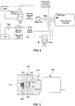
- FIG. 2 is a diagram according to an embodiment of the present disclosure, illustrating a configuration of a hydrogen supply system of a fuel cell system.
- a shut-off valve 300 may be provided between a high-pressure sensor 200 and the high-pressure container.
- components such as the high-pressure container, the solenoid valve, a filter, and a manual valve illustrated in FIG. 2 as components which may be generally adopted and used in a hydrogen supply system of a general fuel cell system in the related art may be selected in a conventional technical scope, a description thereof will be omitted below.
- FIG. 3 is a diagram illustrating the structure of a system for measuring pressure of an in-tank regulator 100 according to an embodiment of the present disclosure.
- the in-tank regulator 100 may be presented.
- the in-tank regulator 100 is directly connected to or in communication with the inside of the high-pressure container, and as a result, the in-tank regulator 100 may share a high-pressure in the high-pressure container.
- the in-tank regulator 100 may have a direct-pipe flow path 110 therein.
- the in-tank regulator 100 may be directly connected to or in communication with the inside of the high-pressure container through the direct-pipe flow path 110.
- the direct-pipe flow path 110 of the present disclosure may be regarded as a flow path extended from the inside of the high-pressure container. Accordingly, the pressure of the direct-pipe flow path 110 may be continuously maintained to be the same as the pressure of the inside of the high-pressure container. Therefore, the pressure measured in the direct-pipe flow path 110 may be determined as the pressure of the inside of the high-pressure container.
- the direct-pipe flow path 110 is not limited to a cross-sectional shape thereof and may preferably have a cylindrical shape. Further, the width of the direct-pipe flow path 110 is permissible if gas or a fluid may flow through the corresponding direct-pipe flow path 110 and the width of the direct-pipe flow path 110 may be formed differently depending on a specific point or a specific position.
- a protrusion 120 of the direct-pipe flow path 110 may be formed at one point of the direct-pipe flow path 110.
- the protrusion 120 may be formed at a point where the shut-off valve 300 and the high-pressure sensor 200 meet in the direct-pipe flow path 110.
- the shape of the protrusion 120 is not limited, however, a shape in which the protrusion 120 contacts one end of the shut-off valve 300 to close the direct-pipe flow path 110 is permissible and preferably, the protrusion 120 may be formed to protrude from an internal cross-section of the direct-pipe flow path 110 with a predetermined size.
- a diameter of the direct-pipe flow path 110 may increase at an end of the in-tank regulator 100.
- the high-pressure sensor 200 may be inserted, connected, or fastened into the direct flow path 110 of which the diameter increases.
- a method in which the high-pressure sensor 200 is inserted, connected, or fastened into the direct-pipe flow path 110 is not limited, however, a method that may maintain airtightness between the high-pressure sensor 200 and the direct-pipe flow path 110 may be used.
- a screw groove may be dug at a point where the high-pressure sensor 200 is inserted into the direct-pipe flow path 110 and a separate screw valley corresponding to a screw groove of the high-pressure sensor 200 may be formed at a point of the direct-pipe flow path 110, into which the high-pressure sensor 200 is inserted. Therefore, the high-pressure sensor 200 and the direct-pipe flow path 110, that is, the regulator 100 may be fastened with each other by a screw fastening scheme. Furthermore, a sealing member for further maintaining the airtightness between the high-pressure sensor 200 and the direct-pipe flow path 110 may be provided at a point where the high-pressure sensor 200 and the direct-pipe flow path 110 contact each other. Preferably, an O-ring may be used. That is, referring to FIG. 3 , the direct-pipe flow path 110 passing through the protrusion 120 may be provided in a structure in which the diameter of the direct-pipe flow path 110 increases stepwise.
- the shut-off valve 300 may include a component for fastening with the regulator 100, in detail, the direct-pipe flow path 110 in the regulator.
- the fastening method of the shut-off valve 300 and the in-tank regulator 100, in detail, the direct-pipe flow path 110 in the regulator is not limited, and preferably, the shut-off valve 300 and the direct-pipe flow path 110 may be fastened by the screw fastening scheme.
- a sealing member may be included at the point where the shut-off valve 300 and the direct-pipe flow path 110 are screw-fastened, which may seal the shut-off valve 300 and the direct-pipe flow path 110 and prevent vibration.
- the O-ring may be provided between the shut-off valve 300 and the direct-pipe flow path 110.
- the shut-off valve 300 may include a taper portion 310 disposed in the protrusion 120 of the direct-pipe flow path 110.
- a smallest width of the taper portion 310 may be smaller than that of a pupil formed by the protrusion 120, and a largest width of the taper portion may be larger than that of the pupil formed by the protrusion 120 and smaller than that of the direct-pipe flow path 110. Therefore, the taper portion 310 may principally freely move on the direct-pipe flow path 110.
- the taper portion 310 when the taper portion 310 is inserted into the protrusion 120, the taper portion 310 may be inserted by penetrating the protrusion 120 up to one point of the taper portion 310 where the width of the protrusion 120 and the width of the taper portion 310 are the same as each other. That is, in the present disclosure, one pointed portion of the taper portion 310 may be configured to be inserted into the pupil formed by the protrusion 120.
- the direct-pipe flow path 110 extended from the high-pressure container may be closed.
- the high-pressure sensor 200 which may be used in the present disclosure may include a sensor 220 and a fastening portion 210.
- the sensor 220 of the high-pressure sensor 200 may be formed on one end of the high-pressure sensor 200 and the width of the sensor 220 may be formed to be smaller than the pupil formed by the protrusion 120 of the direct-pipe flow path 110. Therefore, when the high-pressure sensor 200 is mounted on or inserted into the regulator 100, in detail, the direct-pipe flow path 110 in the regulator, the sensor 220 may be inserted into the pupil formed by the protrusion 120 of the direct-pipe flow path 110.
- the high-pressure sensor 200 may be provided to have multiple cylindrical cylinders having diameters with different lengths.
- the high-pressure sensor 200 may be provided to include the cylindrical sensor 220 having the smallest width, a cylindrical insertion portion having a larger width than the sensor 220 through the sensor 220, the cylindrical fastening portion 210 having the larger width than the insertion portion and having a screw groove for screw fastening, which is dug through the insertion portion, and a cylindrical operation unit exposed to the outside and having the largest width.
- the sealing member may be provided, which is used for sealing the high-pressure sensor 200 and the regulator 100, in detail, the direct-pipe flow path 110 of the regulator and preventing vibration.
- the O-ring may be inserted between the insertion portion of the high-pressure sensor 200 and the direct-pipe flow path 110 in the regulator.
- FIG. 4 is a diagram illustrating a coping logic with a leak of the direct-pipe flow path 110, an error of the high-pressure sensor 200, and/or a case where the sealing member is damaged in the high-pressure container on which the in-tank regulator 100 is mounted in the related art.
- the high pressure in the direct-pipe flow path 110 may be just exposed to the outside.
- the high-pressure sensor 200 may be fastened with the in-tank regulator 100, in detail, the direct-pipe flow path 110 in the regulator.
- the sensor 220 of the high-pressure sensor 200 may contact the taper portion 310 of the shut-off valve 300 through the pupil formed by the protrusion 120 of the direct-pipe flow path 110.
- the sensor 220 of the high-pressure sensor 200 may press a tip of the taper portion 310 of the shut-off valve 300 in the direct-pipe flow path 110 toward the high-pressure container.
- the shut-off valve 300 may be switched to an opened state as the taper portion 310 is pressed.
- the sensor 220 of the high-pressure sensor 200 directly accesses and is directly connected with the direct-pipe flow path 110 and the sensor 220 of the high-pressure sensor 200 may be just exposed to the internal pressure of the direct-pipe flow path 110 and the internal pressure of the high-pressure container. Therefore, while the high-pressure sensor 200 is fastened to the in-tank regulator 100, in detail, the direct-pipe flow path 110 of the regulator, the sensor 220 of the high-pressure sensor 200 may accurately detect the internal pressure of the high-pressure container.
- the sensor 220 of the high-pressure sensor 200 may be inserted into the pupil formed by the protrusion 120 of the direct-pipe flow path 110 and the sensor 220 of the high-pressure sensor 200 pushes the taper portion 310 of the shut-off valve 300 toward the high-pressure container on the direct-pipe flow path 110, and as a result, the sensor 220 of the high-pressure sensor 200 may be exposed to a pressure which is the same as the internal pressure of the high-pressure container.
- FIG. 5 is a diagram according to an embodiment in which the high-pressure sensor 200 is separated from the in-tank regulator 100 in the present disclosure and illustrates a flow for illustrating a series of the processes of separating and removing, and thereafter, remounting and refastening the high-pressure sensor 200 in the system for measuring pressure of an in-tank regulator.
- the high-pressure sensor 200 may be separated from the in-tank regulator 100, in detail, the direct-pipe flow path 110 in the regulator in order to replace and repair a member in which the abnormal situations occur.
- the shut-off valve 300 When the high-pressure sensor 200 is separated from the direct-pipe flow path 110 of the regulator, the shut-off valve 300 may be naturally restored to the normally closed (NC) state and may close the direct-pipe flow path 110. Further, the airtightness may be further maintained between the shut-off valve 300 and the protrusion 120 of the direct-pipe flow path 110 even by force with which the high pressure of the high-pressure container formed in the direct-pipe flow path 110 pushes the shut-off valve 300 toward the protrusion 120 of the direct-pipe flow path 110 as well as closing the shut-off valve 300.
- the sealing member After the high-pressure sensor 200 is separated from the in-tank regulator 100, the sealing member may be replaced, which is provided between the high-pressure sensor 200 or the high-pressure sensor 200 and the in-tank regulator 100.
- the hydrogen needs to be reinjected so that a predetermined pressure or higher is formed in the high-pressure container in the related art, but since the hydrogen in the high-pressure container maintains the high-pressure state through all processes of carrying out the present disclosure in the present disclosure, an additional time and an additional hydrogen amount required for recharging the hydrogen may be saved.
- shut-off valve 300 shuts off the direct-pipe flow path 110 by the high pressure while detaching/attaching the high-pressure sensor 200, there is an effect in which the gas in the high-pressure container need not be exhausted to the outside in order to attach/detach the high-pressure sensor 200. That is, a repairing process for replacing the high-pressure sensor 200 is simplified to shorten a required time.
- the leak needs to be verified by increasing the pressure of the high-pressure container to a high pressure at a level of approximately 700 bar again in the related art, but in the present disclosure, since a state in which the pressure of the high-pressure container is not exhausted is maintained, it may be easily verified whether the leak occurs within a short time.
- the hydrogen is depressurized by the in-tank regulator 100 positioned in the high-pressure container to be transferred to the hydrogen supply system of the fuel cell system, durability or airtightness of the hydrogen supply system may increase and since the high-pressure line is not formed except for a charging pipe, safety and stability of the hydrogen supply system may increase.
- the shut-off valve is installed at one point of the direct-pipe flow path between the high-pressure container and the high-pressure sensor and whether the high-pressure sensor is attached or detached and whether the shut-off valve is opened or closed synchronize with each other and in detail, when the high-pressure sensor is fastened, the shut-off valve is pressed to be opened and when the high-pressure sensor is separated, the shut-off valve is maintained in a closed state to prevent the high pressure in the direct-pipe flow path from being exposed to the outside.
Abstract
Description
- The present disclosure relates to a system which can measure pressure of a high-pressure tank included in a fuel or hydrogen supply system of a vehicle equipped with a fuel cell system. Particularly, the present disclosure relates to a system for measuring pressure of an in-tank regulator, wherein the system includes a high-pressure sensor, which can be detached from/attached to a direct-pipe flow path connected with the in-tank regulator and a high-pressure tank, and a shut-off valve, thereby synchronizing whether the direct-pipe flow path is opened/closed by the shut-off valve with attaching/detaching the high-pressure sensor.
- In general, a fuel cell system includes a fuel cell stack generating electric energy, a fuel supply system supplying fuel (e.g., hydrogen) to the fuel cell stack, an air supply system supplying air (e.g., oxygen), which is an oxidant required for an electrochemical reaction in the fuel cell stack, a heat and water management system controlling an operation temperature of the fuel cell stack, and the like.
- High-pressure compression hydrogen with a pressure of approximately 700 bars is stored in a hydrogen tank provided in the fuel supply system, that is, a hydrogen supply system, and the compression hydrogen stored in the hydrogen tank is discharged to a high-pressure line according to on/off of a high-pressure controller mounted on an inlet of the hydrogen tank and thereafter, depressurized through a start valve and a hydrogen supply valve to be supplied to the fuel cell stack.
- In the related art, hydrogen of a high-pressure hydrogen tank with a pressure of approximately 700 bars is primarily depressurized to 20 bars or less in a high-pressure regulator. The hydrogen is further depressurized to 4 bars or less through the hydrogen supply valve or an ejector and supplied to the fuel cell stack. When secondary depressurization is performed by using the hydrogen supply valve in the fuel cell system, hydrogen airtightness is secured through a start valve and a hydrogen flow is precisely controlled through the hydrogen supply valve. Further, a hydrogen supply system includes an in-tank regulator which integrates a high-pressure solenoid valve and a depressurization regulator, and therefore stability is very high since the in-tank regulator supplies the hydrogen with a depressurized pressure in the high-pressure hydrogen tank.
- The above information disclosed in this Background section is only for enhancement of understanding of the background of the invention and therefore it may contain information that does not form the prior art that is already known in this country to a person of ordinary skill in the art.
- The present disclosure has been made in an effort to solve the above-described problems associated with prior art.
- A pressure measuring system by the in-tank regulator needs to requisitely include a flow path which is directly extended from the high-pressure container in order to measure the pressure of the high-pressure container, and as a result, it is difficult to cope with an abnormal situation. In particular, when leak occurs in the flow path directly extended from the high-pressure container or the leak occurs in the high-pressure sensor attached to the flow path or a failure occurs in the high-pressure sensor, there are inconvenience and a disadvantage that hydrogen in a high-pressure tank needs to be exhausted in order to remove the high-pressure sensor.
- In one aspect, the present disclosure provides a system for a high pressure of an in-tank regulator, including: a direct-pipe flow path which directly communicates with an inside of a high-pressure container; a high-pressure sensor, of which a portion is movable into the direct-pipe flow path, fastened to and separated from the direct-pipe flow path; and a shut-off valve disposed on the direct-pipe flow path between the high-pressure container and the high-pressure sensor, wherein when the high-pressure sensor is separated from the direct-pipe flow path, the direct-pie flow path is sealed by the shut-off valve.
- In a preferred embodiment, the shut-off valve may further include a taper portion formed on one end of the high-pressure sensor.
- In another preferred embodiment, the width of the taper portion may decrease toward the high-pressure sensor.
- Further in another preferred embodiment, the high-pressure sensor may further include a fastening portion fastening the high-pressure sensor and the regulator to each other, and a sensor configured to measure the pressure of the direct-pipe flow path, and the fastening portion may fasten the regulator and the high-pressure sensor by screw fastening.
- In yet another preferred embodiment, the direct-pipe flow path may have a protrusion formed at one point thereof, and the protrusion may be formed between the shut-off valve and the high-pressure sensor.
- In still yet another preferred embodiment, when the high-pressure sensor is moved into the direct-pipe flow path, the sensor may push the taper portion toward the inside of the direct-pipe flow path.
- In a further preferred embodiment, when the high-pressure sensor separated from the regulator, the taper portion may push the protrusion toward the outside of the direct-pipe flow path by high pressure in the direct-pipe flow path.
- In another further preferred embodiment, the sensor is movable into a pupil formed by the protrusion to push the taper portion toward the inside of the direct-pipe flow path.
- In still another preferred embodiment, when external force is not applied to the shut-off valve, the shut-off valve may maintain a normally closed (NC) state.
- The present disclosure provides the following effects through the means for solving problems.
- According to the present disclosure, when a shut-off valve shuts off a direct pipe while a high-pressure is attached/detached, gas in a high-pressure container need not be exhausted to the outside in order to detach/attach the high-pressure sensor. That is, a repairing process for replacing the high-pressure sensor is simplified to shorten a required time.
- In the related art, while the gas is exhausted from the high-pressure container, external leak or a problem in a component can continuously occur, but in the present disclosure, since the high-pressure sensor is attached/detached and the shut-off valve closes a high-pressure line, a time required for coping with abnormal and problematic situations can be remarkably shortened.
- In the case of a gasoline vehicle, as compared with a case in which all gasoline is extracted to the outside in order to replace the component and thereafter the gasoline is reusable, in the present disclosure using the gas as a fuel, when the fuel is exhausted to the outside, the gas cannot but be discharged to the atmosphere, and as a result, it is possible to prevent the fuel from being unnecessarily consumed in that the fuel need not be exhausted.
- After the high-pressure sensor is refastened, the leak needs to be verified by increasing the pressure of the high-pressure container to a high pressure at a level of approximately 700 bars again in the related art, but in the present disclosure, since a state in which the pressure of the high-pressure container is not exhausted is maintained, it may be easily verified whether the leak occurs within a short time.
- Since the hydrogen is depressurized by the in-tank regulator positioned in the high-pressure container to be transferred to the hydrogen supply system of the fuel cell system, durability or airtightness of the hydrogen supply system can increase and since the high-pressure line is not formed except for a charging pipe, safety and stability of the hydrogen supply system can increase.
- Other aspects and preferred embodiments of the disclosure are discussed infra.
- It is understood that the term "vehicle" or "vehicular" or other similar term as used herein is inclusive of motor vehicles in general such as passenger automobiles including sports utility vehicles (SUV), buses, trucks, various commercial vehicles, watercraft including a variety of boats and ships, aircraft, and the like, and includes hybrid vehicles, electric vehicles, plug-in hybrid electric vehicles, hydrogen-powered vehicles and other alternative fuel vehicles (e.g. fuels derived from resources other than petroleum). As referred to herein, a hybrid vehicle is a vehicle that has two or more sources of power, for example both gasoline-powered and electric-powered vehicles.
- The above and other features of the invention are discussed infra.
- The above and other features of the present disclosure will now be described in detail with reference to certain exemplary embodiments thereof illustrated in the accompanying drawings which are given hereinbelow by way of illustration only, and thus are not limitative of the present disclosure, and wherein:
-
FIG. 1 is a diagram illustrating a configuration of a hydrogen supply system of a fuel cell system on which an in-tank regulator is mounted in the related art; -
FIG. 2 is a diagram illustrating a configuration of a hydrogen supply system of a fuel cell system on which an in-tank regulator is mounted according to an embodiment of the present disclosure; -
FIG. 3 is a diagram illustrating a cross-section of a system for measuring pressure of an in-tank regulator according to another embodiment of the present disclosure; -
FIG. 4 is a flowchart illustrating a flow for separating and remounting a high-pressure sensor in a fuel cell system on which an in-tank regulator is mounted in the related art; and -
FIG. 5 is a flowchart illustrating a flow for separating and remounting a high-pressure sensor in a system for measuring pressure of an in-tank regulator according to the present disclosure. - Reference numerals set forth in the Drawings includes reference to the following elements as further discussed below.
- 100: in-tank regulator
- 110: direct-pipe flow path
- 120: protrusion of direct-pipe flow path
- 200: high-pressure sensor
- 210: fastening portion of high-pressure sensor
- 220: sensor of high-pressure sensor
- 300: shut-off valve
- 310: taper portion of shut-off valve
- It should be understood that the appended drawings are not necessarily to scale, presenting a somewhat simplified representation of various preferred features illustrative of the basic principles of the invention. The specific design features of the present disclosure as disclosed herein, including, for example, specific dimensions, orientations, locations, and shapes will be determined in part by the particular intended application and use environment.
- In the figures, reference numbers refer to the same or equivalent parts of the present disclosure throughout the several figures of the drawing.
- Hereinafter reference will now be made in detail to various embodiments of the present disclosure, examples of which are illustrated in the accompanying drawings and described below. While the invention will be described in conjunction with exemplary embodiments, it will be understood that present description is not intended to limit the invention to those exemplary embodiments. On the contrary, the invention is intended to cover not only the exemplary embodiments, but also various alternatives, modifications, equivalents and other embodiments, which may be included within the spirit and scope of the invention as defined by the appended claims.
- Terms including "part' , "unit" , "module" , and the like disclosed in the specification mean a unit that processes at least one function or operation and this may be implemented by hardware or software or a combination of hardware and software.
- A fuel cell system mounted on a vehicle may be generally configured to include a fuel cell stack generating electric energy, a fuel supply device supplying fuel (hydrogen) to the fuel cells stack, an air supply device supplying oxygen in air, which is an oxidant required for an electrochemical reaction to the fuel cell stack, and a cooling system removing reaction heat of the fuel cell stack to the outside of the system and controlling an operation temperature of the fuel cell stack.
-
FIG. 1 is a diagram illustrating a general configuration of a hydrogen supply system that transfers fuel from a high-pressure container to a stack in a fuel cell system and according toFIG. 1 , the high-pressure container storing fuel, a depressurization regulator, a solenoid valve, and the like are illustrated. - In the fuel cell system, a method that stores the hydrogen in the high-pressure container may adopt a high-pressure compression (350 bars and 700 bars compression) scheme. When an external regulator which may be separately provided outside the high-pressure container is used, a high-pressure line should be formed in each solenoid valve. While the vehicle on which the fuel cell system is mounted is driven, that is, while the hydrogen is supplied, a pressure of 350 bars or 700 bars may be continuously applied to the high-pressure line. At parts or points to which the high pressure is continuously applied, durability of a fitting, a valve, and a tube is problematic to influence stability of the entire hydrogen supply system. By considering the problem, when the in-tank regulator is applied instead of the external regulator, the high-pressure line may be eliminated. Furthermore, as the high-pressure line is eliminated, safety may be provided at the time of operating the system, the entire fuel cell system is simplified, and cost is saved.
- However, when the hydrogen supply system is configured to include the in-tank regulator, a separate direct-pipe flow path directly connected with the high-pressure container needs to be requisitely included in order to measure the pressure of the high-pressure container and a high-pressure sensor for measuring the pressure may be provided on the direct-pipe flow path. In the related art, when the high-pressure sensor is separated from the direct-pipe flow path, a problem that the direct-pipe flow path to which the high pressure is applied is exposed to the outside occurs, and as a result, the high-pressure sensor needs to be separated after exhausting all gas in the high-pressure container. The present disclosure is contrived to solve the problem and includes the shut-off valve which may be provided on the direct-pipe flow path in the in-tank regulator. Further, when the high-pressure sensor is separated from the regulator, in detail, the direct-pipe flow path in the regulator, the shut-off valve closes the direct-pipe flow path to prevent the high pressure in the direct-pipe flow path from being exposed to the outside. In addition, according to another embodiment of the present disclosure, the direct-pipe flow path, the shut-off valve, and the high-pressure sensor may be formed at an opposite side of a valve sealed by an end plug rather than at the valve side including a nozzle unit through which the hydrogen is charged/discharged in the high-pressure container. Even in this case, the pressure which is the same as the pressure in the high-pressure container is formed on the direct-pipe flow path formed at the end plug side, and it may be determined whether the shut-off valve is opened or closed by detaching/attaching the high-pressure sensor similarly to the case where the direct-pipe flow path is formed in the in-tank regulator.
- Hereinafter, a configuration and an operating principle of the system for measuring pressure of an in-tank regulator according to the present disclosure will be described in detail with reference to drawings. Furthermore, the present disclosure described below relates to the high-pressure container using the in-tank regulator, and as a result, an in-tank regulator and a regulator are used together, but both sides may mean the same component.
-
FIG. 2 is a diagram according to an embodiment of the present disclosure, illustrating a configuration of a hydrogen supply system of a fuel cell system. InFIG. 2 , it is illustrated that a shut-offvalve 300 may be provided between a high-pressure sensor 200 and the high-pressure container. Further, since components such as the high-pressure container, the solenoid valve, a filter, and a manual valve illustrated inFIG. 2 as components which may be generally adopted and used in a hydrogen supply system of a general fuel cell system in the related art may be selected in a conventional technical scope, a description thereof will be omitted below. -
FIG. 3 is a diagram illustrating the structure of a system for measuring pressure of an in-tank regulator 100 according to an embodiment of the present disclosure. In the system for measuring pressure of an in-tank regulator 100 according to the present disclosure, the in-tank regulator 100 may be presented. The in-tank regulator 100 is directly connected to or in communication with the inside of the high-pressure container, and as a result, the in-tank regulator 100 may share a high-pressure in the high-pressure container. - The in-
tank regulator 100 may have a direct-pipe flow path 110 therein. The in-tank regulator 100 may be directly connected to or in communication with the inside of the high-pressure container through the direct-pipe flow path 110.In other words, the direct-pipe flow path 110 of the present disclosure may be regarded as a flow path extended from the inside of the high-pressure container. Accordingly, the pressure of the direct-pipe flow path 110 may be continuously maintained to be the same as the pressure of the inside of the high-pressure container. Therefore, the pressure measured in the direct-pipe flow path 110 may be determined as the pressure of the inside of the high-pressure container. - The direct-
pipe flow path 110 is not limited to a cross-sectional shape thereof and may preferably have a cylindrical shape. Further, the width of the direct-pipe flow path 110 is permissible if gas or a fluid may flow through the corresponding direct-pipe flow path 110 and the width of the direct-pipe flow path 110 may be formed differently depending on a specific point or a specific position. - A
protrusion 120 of the direct-pipe flow path 110 may be formed at one point of the direct-pipe flow path 110. Theprotrusion 120 may be formed at a point where the shut-offvalve 300 and the high-pressure sensor 200 meet in the direct-pipe flow path 110. The shape of theprotrusion 120 is not limited, however, a shape in which theprotrusion 120 contacts one end of the shut-offvalve 300 to close the direct-pipe flow path 110 is permissible and preferably, theprotrusion 120 may be formed to protrude from an internal cross-section of the direct-pipe flow path 110 with a predetermined size. - In a preferred embodiment of the present disclosure, a diameter of the direct-
pipe flow path 110 may increase at an end of the in-tank regulator 100. The high-pressure sensor 200 may be inserted, connected, or fastened into thedirect flow path 110 of which the diameter increases. In the present disclosure, a method in which the high-pressure sensor 200 is inserted, connected, or fastened into the direct-pipe flow path 110 is not limited, however, a method that may maintain airtightness between the high-pressure sensor 200 and the direct-pipe flow path 110 may be used. Preferably, a screw groove may be dug at a point where the high-pressure sensor 200 is inserted into the direct-pipe flow path 110 and a separate screw valley corresponding to a screw groove of the high-pressure sensor 200 may be formed at a point of the direct-pipe flow path 110, into which the high-pressure sensor 200 is inserted. Therefore, the high-pressure sensor 200 and the direct-pipe flow path 110, that is, theregulator 100 may be fastened with each other by a screw fastening scheme. Furthermore, a sealing member for further maintaining the airtightness between the high-pressure sensor 200 and the direct-pipe flow path 110 may be provided at a point where the high-pressure sensor 200 and the direct-pipe flow path 110 contact each other. Preferably, an O-ring may be used. That is, referring toFIG. 3 , the direct-pipe flow path 110 passing through theprotrusion 120 may be provided in a structure in which the diameter of the direct-pipe flow path 110 increases stepwise. - Meanwhile, as the shut-off
valve 300 used in the present disclosure, a normally closed (NC) valve may be used. The shut-offvalve 300 may include a component for fastening with theregulator 100, in detail, the direct-pipe flow path 110 in the regulator. The fastening method of the shut-offvalve 300 and the in-tank regulator 100, in detail, the direct-pipe flow path 110 in the regulator is not limited, and preferably, the shut-offvalve 300 and the direct-pipe flow path 110 may be fastened by the screw fastening scheme. Further, a sealing member may be included at the point where the shut-offvalve 300 and the direct-pipe flow path 110 are screw-fastened, which may seal the shut-offvalve 300 and the direct-pipe flow path 110 and prevent vibration. Preferably, the O-ring may be provided between the shut-offvalve 300 and the direct-pipe flow path 110. - The shut-off
valve 300 may include ataper portion 310 disposed in theprotrusion 120 of the direct-pipe flow path 110. A smallest width of thetaper portion 310 may be smaller than that of a pupil formed by theprotrusion 120, and a largest width of the taper portion may be larger than that of the pupil formed by theprotrusion 120 and smaller than that of the direct-pipe flow path 110. Therefore, thetaper portion 310 may principally freely move on the direct-pipe flow path 110. However, when thetaper portion 310 is inserted into theprotrusion 120, thetaper portion 310 may be inserted by penetrating theprotrusion 120 up to one point of thetaper portion 310 where the width of theprotrusion 120 and the width of thetaper portion 310 are the same as each other. That is, in the present disclosure, one pointed portion of thetaper portion 310 may be configured to be inserted into the pupil formed by theprotrusion 120. - When the
taper portion 310 of the shut-offvalve 300 is maximally inserted into theprotrusion 120 of the direct-pipe flow path 110, that is, when a gap is filled between thetaper portion 310 and theprotrusion 120 by contacting an inclined surface of thetaper portion 310 and theprotrusion 120, the direct-pipe flow path 110 extended from the high-pressure container may be closed. - Meanwhile, the high-
pressure sensor 200 which may be used in the present disclosure may include asensor 220 and afastening portion 210. Thesensor 220 of the high-pressure sensor 200 may be formed on one end of the high-pressure sensor 200 and the width of thesensor 220 may be formed to be smaller than the pupil formed by theprotrusion 120 of the direct-pipe flow path 110. Therefore, when the high-pressure sensor 200 is mounted on or inserted into theregulator 100, in detail, the direct-pipe flow path 110 in the regulator, thesensor 220 may be inserted into the pupil formed by theprotrusion 120 of the direct-pipe flow path 110. Further, according to the embodiment of the present disclosure, the high-pressure sensor 200 may be provided to have multiple cylindrical cylinders having diameters with different lengths. More preferably, the high-pressure sensor 200 may be provided to include thecylindrical sensor 220 having the smallest width, a cylindrical insertion portion having a larger width than thesensor 220 through thesensor 220, thecylindrical fastening portion 210 having the larger width than the insertion portion and having a screw groove for screw fastening, which is dug through the insertion portion, and a cylindrical operation unit exposed to the outside and having the largest width. Furthermore, the sealing member may be provided, which is used for sealing the high-pressure sensor 200 and theregulator 100, in detail, the direct-pipe flow path 110 of the regulator and preventing vibration. Preferably, the O-ring may be inserted between the insertion portion of the high-pressure sensor 200 and the direct-pipe flow path 110 in the regulator. - Hereinafter, a driving order and a driving principle of the system for measuring pressure of an in-
tank regulator 100 will be described with reference toFIGS. 3 to 5 .FIG. 4 is a diagram illustrating a coping logic with a leak of the direct-pipe flow path 110, an error of the high-pressure sensor 200, and/or a case where the sealing member is damaged in the high-pressure container on which the in-tank regulator 100 is mounted in the related art. According toFIG. 4 , in the direct-pipe flow path 110 on which the in-tank regulator 100 in the related art and the high-pressure sensor 200 are mounted, when the high-pressure sensor 200 is removed or separated from the in-tank regulator 100, the high pressure in the direct-pipe flow path 110 may be just exposed to the outside. In this case, dangerous situations including hydrogen explosion, and the like may be caused, and as a result, complete exhaustion of the high pressure in the high-pressure container and the direct-pipe flow path 110 to the outside needs to be particularly precedently performed before removing or separating the high-pressure sensor 200. - However, referring back to
FIG. 3 , inFIG. 3 , the high-pressure sensor 200 may be fastened with the in-tank regulator 100, in detail, the direct-pipe flow path 110 in the regulator. In this case, thesensor 220 of the high-pressure sensor 200 may contact thetaper portion 310 of the shut-offvalve 300 through the pupil formed by theprotrusion 120 of the direct-pipe flow path 110. Further, thesensor 220 of the high-pressure sensor 200 may press a tip of thetaper portion 310 of the shut-offvalve 300 in the direct-pipe flow path 110 toward the high-pressure container. The shut-offvalve 300 may be switched to an opened state as thetaper portion 310 is pressed. - Accordingly, the
sensor 220 of the high-pressure sensor 200 directly accesses and is directly connected with the direct-pipe flow path 110 and thesensor 220 of the high-pressure sensor 200 may be just exposed to the internal pressure of the direct-pipe flow path 110 and the internal pressure of the high-pressure container. Therefore, while the high-pressure sensor 200 is fastened to the in-tank regulator 100, in detail, the direct-pipe flow path 110 of the regulator, thesensor 220 of the high-pressure sensor 200 may accurately detect the internal pressure of the high-pressure container. - That is, while the high-
pressure sensor 200 is completely closely attached, coupled, or fastened to the direct-pipe flow path 110 through screw fastening, thesensor 220 of the high-pressure sensor 200 may be inserted into the pupil formed by theprotrusion 120 of the direct-pipe flow path 110 and thesensor 220 of the high-pressure sensor 200 pushes thetaper portion 310 of the shut-offvalve 300 toward the high-pressure container on the direct-pipe flow path 110, and as a result, thesensor 220 of the high-pressure sensor 200 may be exposed to a pressure which is the same as the internal pressure of the high-pressure container. -
FIG. 5 is a diagram according to an embodiment in which the high-pressure sensor 200 is separated from the in-tank regulator 100 in the present disclosure and illustrates a flow for illustrating a series of the processes of separating and removing, and thereafter, remounting and refastening the high-pressure sensor 200 in the system for measuring pressure of an in-tank regulator. According toFIG. 5 , when the leak of the direct-pipe flow path 110 occurs, the error of the high-pressure sensor 200 occurs, and/or the sealing member is damaged, the high-pressure sensor 200 may be separated from the in-tank regulator 100, in detail, the direct-pipe flow path 110 in the regulator in order to replace and repair a member in which the abnormal situations occur. - When the high-
pressure sensor 200 is separated from the direct-pipe flow path 110 of the regulator, the shut-offvalve 300 may be naturally restored to the normally closed (NC) state and may close the direct-pipe flow path 110. Further, the airtightness may be further maintained between the shut-offvalve 300 and theprotrusion 120 of the direct-pipe flow path 110 even by force with which the high pressure of the high-pressure container formed in the direct-pipe flow path 110 pushes the shut-offvalve 300 toward theprotrusion 120 of the direct-pipe flow path 110 as well as closing the shut-offvalve 300. After the high-pressure sensor 200 is separated from the in-tank regulator 100, the sealing member may be replaced, which is provided between the high-pressure sensor 200 or the high-pressure sensor 200 and the in-tank regulator 100. - When the high-
pressure sensor 200 is mounted and fastened onto the direct-pipe flow path 110 in the regulator again, the hydrogen needs to be reinjected so that a predetermined pressure or higher is formed in the high-pressure container in the related art, but since the hydrogen in the high-pressure container maintains the high-pressure state through all processes of carrying out the present disclosure in the present disclosure, an additional time and an additional hydrogen amount required for recharging the hydrogen may be saved. - According to the present disclosure described above in detail, since the shut-off
valve 300 shuts off the direct-pipe flow path 110 by the high pressure while detaching/attaching the high-pressure sensor 200, there is an effect in which the gas in the high-pressure container need not be exhausted to the outside in order to attach/detach the high-pressure sensor 200. That is, a repairing process for replacing the high-pressure sensor 200 is simplified to shorten a required time. - In the related art, while the gas is exhausted from the high-pressure container, external leak or a problem in a component continuously occurs, but in the present disclosure, since the high-
pressure sensor 200 is attached/detached and the shut-offvalve 300 closes the high-pressure line, a time required for coping with abnormal and problem situations may be remarkably shortened. - In the case of a gasoline vehicle, as compared with a case in which all gasoline is extracted to the outside in order to replace the component and thereafter, the gasoline is reusable, in the present disclosure using the gas as a fuel, when the fuel is exhausted to the outside, the gas cannot but be discharged to the atmosphere, and as a result, it is possible to prevent the fuel from being unnecessarily consumed in that the fuel need not to be exhausted.
- After the high-
pressure sensor 200 is refastened, the leak needs to be verified by increasing the pressure of the high-pressure container to a high pressure at a level of approximately 700 bar again in the related art, but in the present disclosure, since a state in which the pressure of the high-pressure container is not exhausted is maintained, it may be easily verified whether the leak occurs within a short time. - Since the hydrogen is depressurized by the in-
tank regulator 100 positioned in the high-pressure container to be transferred to the hydrogen supply system of the fuel cell system, durability or airtightness of the hydrogen supply system may increase and since the high-pressure line is not formed except for a charging pipe, safety and stability of the hydrogen supply system may increase. - In a core spirit of the present disclosure, considering that mounting the high-pressure sensor on the direct-pipe flow path which is in direct communication with the high-pressure container is required by adopting the in-tank regulator, the shut-off valve is installed at one point of the direct-pipe flow path between the high-pressure container and the high-pressure sensor and whether the high-pressure sensor is attached or detached and whether the shut-off valve is opened or closed synchronize with each other and in detail, when the high-pressure sensor is fastened, the shut-off valve is pressed to be opened and when the high-pressure sensor is separated, the shut-off valve is maintained in a closed state to prevent the high pressure in the direct-pipe flow path from being exposed to the outside.
- Embodiments of the present disclosure have been explained and described, but it will be appreciated by those skilled in the art that the present disclosure may be modified and changed in various ways without departing from the spirit of the present disclosure described in the claims by the addition, change, deletion or addition of constituent elements, and that the modifications and changes are included in the claims of the present disclosure.
- In describing the embodiment of the present disclosure, detailed description of known function or constitutions will be omitted if they make the gist of the present disclosure unclear. In addition, the used terms as terms which are specially defined in consideration of functions in the embodiment of the present disclosure may vary depending on the intention or usual practice of a user or an operator. Accordingly, the terms need to be defined base on contents throughout this specification. Accordingly, the detailed description of the invention does not intend to limit the present disclosure as the disclosed embodiment and it should be interpreted that the appended claims also include other embodiments.
- The invention has been described in detail with reference to preferred embodiments thereof. However, it will be appreciated by those skilled in the art that changes may be made in these embodiments without departing from the principles and spirit of the invention, the scope of which is defined in the appended claims and their equivalents.
Claims (10)
- A system for measuring pressure of an in-tank regulator, the system comprising:a direct-pipe flow path which directly communicates with an inside of a high-pressure container;a high-pressure sensor, of which a portion is movable into the direct-pipe flow path, fastened to and separated from the direct-pipe flow path; anda shut-off valve disposed on the direct-pipe flow path between the high-pressure container and the high-pressure sensor,wherein when the high-pressure sensor is separated from the direct-pipe flow path, the direct-pipe flow path is sealed by the shut-off valve.
- The system of claim 1, wherein the high-pressure container includes an in-tank regulator, and
the direct-pipe flow path is formed in the in-tank regulator. - The system of claim 1 or 2, wherein the shut-off valve includes a taper portion faces one end of the high-pressure sensor.
- The system of of claim 3, wherein the width of the taper portion decreases toward the high-pressure sensor.
- The system of any one of the preceding claims, wherein the high-pressure sensor includes
a fastening portion fastening the high-pressure sensor and the in-tank regulator to each other, and
a sensor configured to measure the pressure of the direct-pipe flow path, wherein the fastening portion fastens the in-tank regulator and the high-pressure sensor by screw fastening. - The system of any one of the preceding claims, wherein the direct-pipe flow path includes a protrusion formed at one point of the direct-pipe flow path, and the protrusion is formed between the shut-off valve and the high-pressure sensor.
- The system of claim 6, wherein when the portion of the high-pressure sensor is moved into the direct-pipe flow path, the sensor pushes the taper portion toward an inside of the direct-pipe flow path.
- The system of claim 6, wherein when the high-pressure sensor is separated from the in-tank regulator, the taper portion pushes the protrusion toward an outside of the direct-pipe flow path by high pressure in the direct-pipe flow path.
- The system of claim 6, wherein the sensor is movable into a pupil formed by the protrusion to push the taper portion toward the inside of the direct-pipe flow path.
- The system of any one of the preceding claims, wherein when external force is not applied to the shut-off valve, the shut-off valve maintains a normally closed (NC) state.
Applications Claiming Priority (1)
| Application Number | Priority Date | Filing Date | Title |
|---|---|---|---|
| KR1020160171373A KR102429166B1 (en) | 2016-12-15 | 2016-12-15 | The system for measuring high pressure of In-tank regulator |
Publications (2)
| Publication Number | Publication Date |
|---|---|
| EP3336409A1 true EP3336409A1 (en) | 2018-06-20 |
| EP3336409B1 EP3336409B1 (en) | 2022-03-16 |
Family
ID=59968960
Family Applications (1)
| Application Number | Title | Priority Date | Filing Date |
|---|---|---|---|
| EP17192334.5A Active EP3336409B1 (en) | 2016-12-15 | 2017-09-21 | System for measuring high pressure of an in-tank regulator |
Country Status (5)
| Country | Link |
|---|---|
| US (1) | US10868315B2 (en) |
| EP (1) | EP3336409B1 (en) |
| JP (1) | JP6650427B2 (en) |
| KR (1) | KR102429166B1 (en) |
| CN (1) | CN108224084B (en) |
Families Citing this family (5)
| Publication number | Priority date | Publication date | Assignee | Title |
|---|---|---|---|---|
| DE102018220542A1 (en) * | 2018-11-29 | 2020-06-04 | Robert Bosch Gmbh | Tank device for storing compressed fluids with a sensor module arrangement |
| CN113531391A (en) * | 2020-04-14 | 2021-10-22 | 北京优利威科技有限公司 | Sensor sealing connection mode and high-pressure gas cylinder applying same |
| CN113503467B (en) | 2021-07-08 | 2023-07-25 | 亚普汽车部件(开封)有限公司 | High-pressure gas cylinder valve for vehicle |
| KR102582401B1 (en) * | 2023-04-03 | 2023-09-25 | 조광아이엘아이 주식회사 | Two Way Valve Assembly for Hydrogen Storage Tank |
| KR102582397B1 (en) * | 2023-04-03 | 2023-09-25 | 조광아이엘아이 주식회사 | One Way Valve Assembly for Hydrogen Storage Tank |
Citations (3)
| Publication number | Priority date | Publication date | Assignee | Title |
|---|---|---|---|---|
| US20100001851A1 (en) * | 2008-07-04 | 2010-01-07 | Honda Motor Co., Ltd. | Pressure tank and detection method of pressure tank internal abnormality |
| US20110143243A1 (en) * | 2009-12-11 | 2011-06-16 | Gm Global Technology Operations, Inc. | Fuel cell operational methods for hydrogen addition after shutdown |
| US20150176719A1 (en) * | 2013-12-20 | 2015-06-25 | Kia Motors Corporation | Method and apparatus for detecting opening and closing of pilot operated solenoid valve for hydrogen tank |
Family Cites Families (13)
| Publication number | Priority date | Publication date | Assignee | Title |
|---|---|---|---|---|
| FR2583494B1 (en) * | 1985-06-17 | 1988-05-13 | Gazzano Maurice | CLOSING, CONTROLLING, OR PRESSURE REGULATING VALVE AND ITS IMPLEMENTING SYSTEM |
| WO1998054557A1 (en) * | 1997-05-28 | 1998-12-03 | Caterpillar Inc. | Fluid pressure sensor |
| US6629544B2 (en) | 2000-12-11 | 2003-10-07 | Keihin Corporation | Gas pressure-reducing valve |
| CN101375093B (en) | 2006-08-29 | 2010-06-02 | 佳能株式会社 | Connection mechanism for fluid piping and its manufacturing method, and fuel cell system including connection mechanism for fluid piping |
| FR2915800B1 (en) * | 2007-05-03 | 2009-09-18 | Taema Sa | METHOD FOR CONTROLLING A PRESSURIZED FLUID CONTAINER |
| KR100885686B1 (en) | 2007-10-16 | 2009-02-26 | (주)모토닉 | Regulator for reducing gas pressure |
| KR101072360B1 (en) | 2009-01-28 | 2011-10-12 | (주)모토닉 | An inward form regulator |
| KR101113641B1 (en) | 2009-05-12 | 2012-02-14 | 기아자동차주식회사 | Receptacle filter for filling hydrogen |
| JP2011179528A (en) * | 2010-02-26 | 2011-09-15 | Kawasaki Heavy Ind Ltd | Tank internal pressure measurement circuit and tank device provided therewith |
| JP5804751B2 (en) | 2011-04-06 | 2015-11-04 | 本田技研工業株式会社 | High pressure gas supply system |
| KR101340314B1 (en) * | 2011-05-24 | 2013-12-11 | 교통안전공단 | Charging and discharging of hydrogen and, charging status monitoring device of hydrogen high pressure vessel for using separately |
| WO2013183871A1 (en) * | 2012-06-04 | 2013-12-12 | 영도산업 주식회사 | Fluid control valve assembly |
| KR20160087087A (en) | 2015-01-13 | 2016-07-21 | 현대자동차주식회사 | Receptacle for charging hydrogen |
-
2016
- 2016-12-15 KR KR1020160171373A patent/KR102429166B1/en active IP Right Grant
-
2017
- 2017-09-20 US US15/710,525 patent/US10868315B2/en active Active
- 2017-09-21 EP EP17192334.5A patent/EP3336409B1/en active Active
- 2017-09-21 JP JP2017181234A patent/JP6650427B2/en active Active
- 2017-09-25 CN CN201710876242.0A patent/CN108224084B/en active Active
Patent Citations (3)
| Publication number | Priority date | Publication date | Assignee | Title |
|---|---|---|---|---|
| US20100001851A1 (en) * | 2008-07-04 | 2010-01-07 | Honda Motor Co., Ltd. | Pressure tank and detection method of pressure tank internal abnormality |
| US20110143243A1 (en) * | 2009-12-11 | 2011-06-16 | Gm Global Technology Operations, Inc. | Fuel cell operational methods for hydrogen addition after shutdown |
| US20150176719A1 (en) * | 2013-12-20 | 2015-06-25 | Kia Motors Corporation | Method and apparatus for detecting opening and closing of pilot operated solenoid valve for hydrogen tank |
Also Published As
| Publication number | Publication date |
|---|---|
| KR102429166B1 (en) | 2022-08-03 |
| US20180175410A1 (en) | 2018-06-21 |
| JP6650427B2 (en) | 2020-02-19 |
| JP2018096537A (en) | 2018-06-21 |
| CN108224084B (en) | 2021-10-26 |
| KR20180069307A (en) | 2018-06-25 |
| EP3336409B1 (en) | 2022-03-16 |
| CN108224084A (en) | 2018-06-29 |
| US10868315B2 (en) | 2020-12-15 |
Similar Documents
| Publication | Publication Date | Title |
|---|---|---|
| EP3336409B1 (en) | System for measuring high pressure of an in-tank regulator | |
| EP3309433B1 (en) | Safe valve for high pressure regulator | |
| US10209158B2 (en) | Apparatus and method for detecting leakage in hydrogen tank of hydrogen fuel cell vehicle | |
| US8647758B2 (en) | Electrochemical energy storage device | |
| CN110178255B (en) | Method for determining the tightness of a fuel cell stack | |
| US20130052553A1 (en) | High pressure gas supply system and fuel cell system | |
| US20080110514A1 (en) | Fuel Tank System | |
| JP2014092282A (en) | Filler neck assembly with stop valve | |
| US20180208052A1 (en) | Pressure Container System for a Motor Vehicle, Motor Vehicle and Method for Interrupting a Fluid Connection | |
| US9960436B2 (en) | Ion filter life perception device for fuel cell vehicle | |
| US10727507B2 (en) | Fuel cell system including rupture part between hydrogen supply valve and hydrogen shut-off valve | |
| US20160197363A1 (en) | Ion filter lifetime perception device for fuel cell vehicle | |
| KR20090034990A (en) | Receptacle | |
| KR20180095984A (en) | The method for detecting malfunction of the high pressure cylinder disposed in a fuel cell system | |
| CN216925972U (en) | Tightness detection device | |
| CN108317392B (en) | Fuel cell system and control method for minimizing high pressure line of hydrogen supply system | |
| JP2003113983A (en) | Fluid connector device | |
| US10957927B2 (en) | Fuel cell system and control method of the same | |
| US10468698B2 (en) | Method of eliminating leakage from fuel tank valve | |
| KR102652910B1 (en) | Adapter For Leak Test And Integrated Leak Test Equipment Including The Same | |
| CN115117393A (en) | Hydrogen supply system for forklift | |
| JP5161430B2 (en) | Valve heating system | |
| KR102563575B1 (en) | Regulator fault diagnosis method for high pressure gas tank | |
| KR20230036963A (en) | Refueling adapter for alternative fuel vehicle and method for refueling |
Legal Events
| Date | Code | Title | Description |
|---|---|---|---|
| PUAI | Public reference made under article 153(3) epc to a published international application that has entered the european phase |
Free format text: ORIGINAL CODE: 0009012 |
|
| STAA | Information on the status of an ep patent application or granted ep patent |
Free format text: STATUS: THE APPLICATION HAS BEEN PUBLISHED |
|
| AK | Designated contracting states |
Kind code of ref document: A1 Designated state(s): AL AT BE BG CH CY CZ DE DK EE ES FI FR GB GR HR HU IE IS IT LI LT LU LV MC MK MT NL NO PL PT RO RS SE SI SK SM TR |
|
| AX | Request for extension of the european patent |
Extension state: BA ME |
|
| STAA | Information on the status of an ep patent application or granted ep patent |
Free format text: STATUS: REQUEST FOR EXAMINATION WAS MADE |
|
| 17P | Request for examination filed |
Effective date: 20181114 |
|
| RBV | Designated contracting states (corrected) |
Designated state(s): AL AT BE BG CH CY CZ DE DK EE ES FI FR GB GR HR HU IE IS IT LI LT LU LV MC MK MT NL NO PL PT RO RS SE SI SK SM TR |
|
| STAA | Information on the status of an ep patent application or granted ep patent |
Free format text: STATUS: REQUEST FOR EXAMINATION WAS MADE |
|
| STAA | Information on the status of an ep patent application or granted ep patent |
Free format text: STATUS: EXAMINATION IS IN PROGRESS |
|
| 17Q | First examination report despatched |
Effective date: 20210430 |
|
| RAP3 | Party data changed (applicant data changed or rights of an application transferred) |
Owner name: KIA CORPORATION Owner name: HYUNDAI MOTOR COMPANY |
|
| GRAP | Despatch of communication of intention to grant a patent |
Free format text: ORIGINAL CODE: EPIDOSNIGR1 |
|
| STAA | Information on the status of an ep patent application or granted ep patent |
Free format text: STATUS: GRANT OF PATENT IS INTENDED |
|
| INTG | Intention to grant announced |
Effective date: 20210927 |
|
| GRAS | Grant fee paid |
Free format text: ORIGINAL CODE: EPIDOSNIGR3 |
|
| GRAA | (expected) grant |
Free format text: ORIGINAL CODE: 0009210 |
|
| STAA | Information on the status of an ep patent application or granted ep patent |
Free format text: STATUS: THE PATENT HAS BEEN GRANTED |
|
| AK | Designated contracting states |
Kind code of ref document: B1 Designated state(s): AL AT BE BG CH CY CZ DE DK EE ES FI FR GB GR HR HU IE IS IT LI LT LU LV MC MK MT NL NO PL PT RO RS SE SI SK SM TR |
|
| REG | Reference to a national code |
Ref country code: GB Ref legal event code: FG4D |
|
| REG | Reference to a national code |
Ref country code: CH Ref legal event code: EP Ref country code: DE Ref legal event code: R096 Ref document number: 602017054588 Country of ref document: DE |
|
| REG | Reference to a national code |
Ref country code: IE Ref legal event code: FG4D |
|
| REG | Reference to a national code |
Ref country code: AT Ref legal event code: REF Ref document number: 1476124 Country of ref document: AT Kind code of ref document: T Effective date: 20220415 |
|
| REG | Reference to a national code |
Ref country code: LT Ref legal event code: MG9D |
|
| PG25 | Lapsed in a contracting state [announced via postgrant information from national office to epo] |
Ref country code: SE Free format text: LAPSE BECAUSE OF FAILURE TO SUBMIT A TRANSLATION OF THE DESCRIPTION OR TO PAY THE FEE WITHIN THE PRESCRIBED TIME-LIMIT Effective date: 20220316 Ref country code: RS Free format text: LAPSE BECAUSE OF FAILURE TO SUBMIT A TRANSLATION OF THE DESCRIPTION OR TO PAY THE FEE WITHIN THE PRESCRIBED TIME-LIMIT Effective date: 20220316 Ref country code: NO Free format text: LAPSE BECAUSE OF FAILURE TO SUBMIT A TRANSLATION OF THE DESCRIPTION OR TO PAY THE FEE WITHIN THE PRESCRIBED TIME-LIMIT Effective date: 20220616 Ref country code: LT Free format text: LAPSE BECAUSE OF FAILURE TO SUBMIT A TRANSLATION OF THE DESCRIPTION OR TO PAY THE FEE WITHIN THE PRESCRIBED TIME-LIMIT Effective date: 20220316 Ref country code: HR Free format text: LAPSE BECAUSE OF FAILURE TO SUBMIT A TRANSLATION OF THE DESCRIPTION OR TO PAY THE FEE WITHIN THE PRESCRIBED TIME-LIMIT Effective date: 20220316 Ref country code: BG Free format text: LAPSE BECAUSE OF FAILURE TO SUBMIT A TRANSLATION OF THE DESCRIPTION OR TO PAY THE FEE WITHIN THE PRESCRIBED TIME-LIMIT Effective date: 20220616 |
|
| REG | Reference to a national code |
Ref country code: AT Ref legal event code: MK05 Ref document number: 1476124 Country of ref document: AT Kind code of ref document: T Effective date: 20220316 |
|
| PG25 | Lapsed in a contracting state [announced via postgrant information from national office to epo] |
Ref country code: LV Free format text: LAPSE BECAUSE OF FAILURE TO SUBMIT A TRANSLATION OF THE DESCRIPTION OR TO PAY THE FEE WITHIN THE PRESCRIBED TIME-LIMIT Effective date: 20220316 Ref country code: GR Free format text: LAPSE BECAUSE OF FAILURE TO SUBMIT A TRANSLATION OF THE DESCRIPTION OR TO PAY THE FEE WITHIN THE PRESCRIBED TIME-LIMIT Effective date: 20220617 Ref country code: FI Free format text: LAPSE BECAUSE OF FAILURE TO SUBMIT A TRANSLATION OF THE DESCRIPTION OR TO PAY THE FEE WITHIN THE PRESCRIBED TIME-LIMIT Effective date: 20220316 |
|
| PG25 | Lapsed in a contracting state [announced via postgrant information from national office to epo] |
Ref country code: NL Free format text: LAPSE BECAUSE OF FAILURE TO SUBMIT A TRANSLATION OF THE DESCRIPTION OR TO PAY THE FEE WITHIN THE PRESCRIBED TIME-LIMIT Effective date: 20220316 |
|
| PG25 | Lapsed in a contracting state [announced via postgrant information from national office to epo] |
Ref country code: SM Free format text: LAPSE BECAUSE OF FAILURE TO SUBMIT A TRANSLATION OF THE DESCRIPTION OR TO PAY THE FEE WITHIN THE PRESCRIBED TIME-LIMIT Effective date: 20220316 Ref country code: SK Free format text: LAPSE BECAUSE OF FAILURE TO SUBMIT A TRANSLATION OF THE DESCRIPTION OR TO PAY THE FEE WITHIN THE PRESCRIBED TIME-LIMIT Effective date: 20220316 Ref country code: RO Free format text: LAPSE BECAUSE OF FAILURE TO SUBMIT A TRANSLATION OF THE DESCRIPTION OR TO PAY THE FEE WITHIN THE PRESCRIBED TIME-LIMIT Effective date: 20220316 Ref country code: PT Free format text: LAPSE BECAUSE OF FAILURE TO SUBMIT A TRANSLATION OF THE DESCRIPTION OR TO PAY THE FEE WITHIN THE PRESCRIBED TIME-LIMIT Effective date: 20220718 Ref country code: ES Free format text: LAPSE BECAUSE OF FAILURE TO SUBMIT A TRANSLATION OF THE DESCRIPTION OR TO PAY THE FEE WITHIN THE PRESCRIBED TIME-LIMIT Effective date: 20220316 Ref country code: EE Free format text: LAPSE BECAUSE OF FAILURE TO SUBMIT A TRANSLATION OF THE DESCRIPTION OR TO PAY THE FEE WITHIN THE PRESCRIBED TIME-LIMIT Effective date: 20220316 Ref country code: CZ Free format text: LAPSE BECAUSE OF FAILURE TO SUBMIT A TRANSLATION OF THE DESCRIPTION OR TO PAY THE FEE WITHIN THE PRESCRIBED TIME-LIMIT Effective date: 20220316 Ref country code: AT Free format text: LAPSE BECAUSE OF FAILURE TO SUBMIT A TRANSLATION OF THE DESCRIPTION OR TO PAY THE FEE WITHIN THE PRESCRIBED TIME-LIMIT Effective date: 20220316 |
|
| PG25 | Lapsed in a contracting state [announced via postgrant information from national office to epo] |
Ref country code: PL Free format text: LAPSE BECAUSE OF FAILURE TO SUBMIT A TRANSLATION OF THE DESCRIPTION OR TO PAY THE FEE WITHIN THE PRESCRIBED TIME-LIMIT Effective date: 20220316 Ref country code: IS Free format text: LAPSE BECAUSE OF FAILURE TO SUBMIT A TRANSLATION OF THE DESCRIPTION OR TO PAY THE FEE WITHIN THE PRESCRIBED TIME-LIMIT Effective date: 20220716 Ref country code: AL Free format text: LAPSE BECAUSE OF FAILURE TO SUBMIT A TRANSLATION OF THE DESCRIPTION OR TO PAY THE FEE WITHIN THE PRESCRIBED TIME-LIMIT Effective date: 20220316 |
|
| REG | Reference to a national code |
Ref country code: DE Ref legal event code: R097 Ref document number: 602017054588 Country of ref document: DE |
|
| PLBE | No opposition filed within time limit |
Free format text: ORIGINAL CODE: 0009261 |
|
| STAA | Information on the status of an ep patent application or granted ep patent |
Free format text: STATUS: NO OPPOSITION FILED WITHIN TIME LIMIT |
|
| PG25 | Lapsed in a contracting state [announced via postgrant information from national office to epo] |
Ref country code: DK Free format text: LAPSE BECAUSE OF FAILURE TO SUBMIT A TRANSLATION OF THE DESCRIPTION OR TO PAY THE FEE WITHIN THE PRESCRIBED TIME-LIMIT Effective date: 20220316 |
|
| 26N | No opposition filed |
Effective date: 20221219 |
|
| PG25 | Lapsed in a contracting state [announced via postgrant information from national office to epo] |
Ref country code: SI Free format text: LAPSE BECAUSE OF FAILURE TO SUBMIT A TRANSLATION OF THE DESCRIPTION OR TO PAY THE FEE WITHIN THE PRESCRIBED TIME-LIMIT Effective date: 20220316 |
|
| PG25 | Lapsed in a contracting state [announced via postgrant information from national office to epo] |
Ref country code: MC Free format text: LAPSE BECAUSE OF FAILURE TO SUBMIT A TRANSLATION OF THE DESCRIPTION OR TO PAY THE FEE WITHIN THE PRESCRIBED TIME-LIMIT Effective date: 20220316 |
|
| REG | Reference to a national code |
Ref country code: CH Ref legal event code: PL |
|
| REG | Reference to a national code |
Ref country code: BE Ref legal event code: MM Effective date: 20220930 |
|
| P01 | Opt-out of the competence of the unified patent court (upc) registered |
Effective date: 20230424 |
|
| PG25 | Lapsed in a contracting state [announced via postgrant information from national office to epo] |
Ref country code: LU Free format text: LAPSE BECAUSE OF NON-PAYMENT OF DUE FEES Effective date: 20220921 |
|
| PG25 | Lapsed in a contracting state [announced via postgrant information from national office to epo] |
Ref country code: LI Free format text: LAPSE BECAUSE OF NON-PAYMENT OF DUE FEES Effective date: 20220930 Ref country code: IT Free format text: LAPSE BECAUSE OF FAILURE TO SUBMIT A TRANSLATION OF THE DESCRIPTION OR TO PAY THE FEE WITHIN THE PRESCRIBED TIME-LIMIT Effective date: 20220316 Ref country code: IE Free format text: LAPSE BECAUSE OF NON-PAYMENT OF DUE FEES Effective date: 20220921 Ref country code: CH Free format text: LAPSE BECAUSE OF NON-PAYMENT OF DUE FEES Effective date: 20220930 |
|
| PG25 | Lapsed in a contracting state [announced via postgrant information from national office to epo] |
Ref country code: BE Free format text: LAPSE BECAUSE OF NON-PAYMENT OF DUE FEES Effective date: 20220930 |
|
| PGFP | Annual fee paid to national office [announced via postgrant information from national office to epo] |
Ref country code: GB Payment date: 20230821 Year of fee payment: 7 |
|
| PGFP | Annual fee paid to national office [announced via postgrant information from national office to epo] |
Ref country code: FR Payment date: 20230821 Year of fee payment: 7 Ref country code: DE Payment date: 20230822 Year of fee payment: 7 |
|
| PG25 | Lapsed in a contracting state [announced via postgrant information from national office to epo] |
Ref country code: HU Free format text: LAPSE BECAUSE OF FAILURE TO SUBMIT A TRANSLATION OF THE DESCRIPTION OR TO PAY THE FEE WITHIN THE PRESCRIBED TIME-LIMIT; INVALID AB INITIO Effective date: 20170921 |