EP3336375B1 - Friction device and a friction damper comprising such a friction device - Google Patents
Friction device and a friction damper comprising such a friction device Download PDFInfo
- Publication number
- EP3336375B1 EP3336375B1 EP17206063.4A EP17206063A EP3336375B1 EP 3336375 B1 EP3336375 B1 EP 3336375B1 EP 17206063 A EP17206063 A EP 17206063A EP 3336375 B1 EP3336375 B1 EP 3336375B1
- Authority
- EP
- European Patent Office
- Prior art keywords
- friction lining
- friction
- frictional
- carrier
- adjustment
- Prior art date
- Legal status (The legal status is an assumption and is not a legal conclusion. Google has not performed a legal analysis and makes no representation as to the accuracy of the status listed.)
- Active
Links
- 238000003825 pressing Methods 0.000 claims description 30
- 238000006073 displacement reaction Methods 0.000 description 44
- 230000000694 effects Effects 0.000 description 14
- 239000000969 carrier Substances 0.000 description 7
- 238000004873 anchoring Methods 0.000 description 6
- 239000000463 material Substances 0.000 description 6
- 238000013016 damping Methods 0.000 description 2
- 238000007373 indentation Methods 0.000 description 2
- 230000003993 interaction Effects 0.000 description 2
- 230000000750 progressive effect Effects 0.000 description 2
- 238000005406 washing Methods 0.000 description 2
- 239000000853 adhesive Substances 0.000 description 1
- 238000004026 adhesive bonding Methods 0.000 description 1
- 230000001070 adhesive effect Effects 0.000 description 1
- 230000005540 biological transmission Effects 0.000 description 1
- 230000006835 compression Effects 0.000 description 1
- 238000007906 compression Methods 0.000 description 1
- 238000010276 construction Methods 0.000 description 1
- 238000004146 energy storage Methods 0.000 description 1
- 239000006260 foam Substances 0.000 description 1
- 239000006261 foam material Substances 0.000 description 1
- 238000004519 manufacturing process Methods 0.000 description 1
- 230000013011 mating Effects 0.000 description 1
- 230000000284 resting effect Effects 0.000 description 1
- 238000003892 spreading Methods 0.000 description 1
- 230000007704 transition Effects 0.000 description 1
Images


Classifications
-
- F—MECHANICAL ENGINEERING; LIGHTING; HEATING; WEAPONS; BLASTING
- F16—ENGINEERING ELEMENTS AND UNITS; GENERAL MEASURES FOR PRODUCING AND MAINTAINING EFFECTIVE FUNCTIONING OF MACHINES OR INSTALLATIONS; THERMAL INSULATION IN GENERAL
- F16F—SPRINGS; SHOCK-ABSORBERS; MEANS FOR DAMPING VIBRATION
- F16F7/00—Vibration-dampers; Shock-absorbers
- F16F7/08—Vibration-dampers; Shock-absorbers with friction surfaces rectilinearly movable along each other
- F16F7/082—Vibration-dampers; Shock-absorbers with friction surfaces rectilinearly movable along each other and characterised by damping force adjustment means
-
- F—MECHANICAL ENGINEERING; LIGHTING; HEATING; WEAPONS; BLASTING
- F16—ENGINEERING ELEMENTS AND UNITS; GENERAL MEASURES FOR PRODUCING AND MAINTAINING EFFECTIVE FUNCTIONING OF MACHINES OR INSTALLATIONS; THERMAL INSULATION IN GENERAL
- F16F—SPRINGS; SHOCK-ABSORBERS; MEANS FOR DAMPING VIBRATION
- F16F7/00—Vibration-dampers; Shock-absorbers
- F16F7/08—Vibration-dampers; Shock-absorbers with friction surfaces rectilinearly movable along each other
- F16F7/09—Vibration-dampers; Shock-absorbers with friction surfaces rectilinearly movable along each other in dampers of the cylinder-and-piston type
- F16F7/095—Vibration-dampers; Shock-absorbers with friction surfaces rectilinearly movable along each other in dampers of the cylinder-and-piston type frictional elements brought into engagement by movement along a surface oblique to the axis of the cylinder, e.g. interaction of wedge-shaped elements
-
- D—TEXTILES; PAPER
- D06—TREATMENT OF TEXTILES OR THE LIKE; LAUNDERING; FLEXIBLE MATERIALS NOT OTHERWISE PROVIDED FOR
- D06F—LAUNDERING, DRYING, IRONING, PRESSING OR FOLDING TEXTILE ARTICLES
- D06F37/00—Details specific to washing machines covered by groups D06F21/00 - D06F25/00
- D06F37/20—Mountings, e.g. resilient mountings, for the rotary receptacle, motor, tub or casing; Preventing or damping vibrations
-
- F—MECHANICAL ENGINEERING; LIGHTING; HEATING; WEAPONS; BLASTING
- F16—ENGINEERING ELEMENTS AND UNITS; GENERAL MEASURES FOR PRODUCING AND MAINTAINING EFFECTIVE FUNCTIONING OF MACHINES OR INSTALLATIONS; THERMAL INSULATION IN GENERAL
- F16F—SPRINGS; SHOCK-ABSORBERS; MEANS FOR DAMPING VIBRATION
- F16F2222/00—Special physical effects, e.g. nature of damping effects
- F16F2222/04—Friction
Definitions
- the invention relates to a friction device for a friction damper and a friction damper with such a friction device.
- Friction dampers are, for example, designed to generate friction damping between two movably connected components GB 1 284 536 A , DE 30 16 915 A1 , EP 0 763 670 A2 , US 3,866,724 , DE 19 55 235 U , EP 2 541 092 A2 and US 6,279,693 B1 known.
- the invention has for its object to improve the functionality of a friction damper.
- a friction effect that can be achieved with a friction damper is variable, in particular specifically variable.
- a frictional force that can be exerted by means of a friction device to achieve the frictional effect can be set in a targeted manner.
- the variable adjustability of the friction effect is possible directly and without complications.
- the force-adjustable friction damper with such a friction device can be used flexibly and in particular enables use in a product which can be set differently, in particular as required Should have friction effects.
- Such a friction damper can be used advantageously, for example, in washing machines.
- a single force-adjustable friction damper according to the invention would be sufficient, which, depending on the intended use, can be set in the washing machine with the required friction force.
- a friction damper can be used to dampen vibrations, whereby the friction effect can be individually adjusted and adjusted to the actual vibration conditions in the machine.
- the friction damper according to the invention can also be used in fitness equipment. By changing the frictional effect, the resulting counterforce can be changed in a targeted manner.
- the friction device comprises a friction lining carrier, at least one adjustable friction lining arranged on the friction lining carrier as well as an adjusting element for the adjustable arrangement of the at least one friction lining on the friction lining carrier.
- the resulting friction effect is changed by adjusting the at least one friction lining.
- the friction lining carrier is in particular made in one piece.
- the at least one friction lining is fixed to the friction lining carrier with respect to the longitudinal axis of the housing.
- the at least one friction lining is fixed on the friction lining carrier with respect to the longitudinal axis in the axial direction and / or in the circumferential direction about the longitudinal axis. It is also conceivable for the friction lining to be fixed to the friction lining carrier exclusively in the axial direction with respect to the longitudinal axis and, in particular in the circumferential direction, not to be fixed, in particular displaceable, around the longitudinal axis.
- a window-like radial recess of the friction lining carrier for the at least one adjustable friction lining enables an uncomplicated radial displacement of the friction lining.
- the application of friction is simplified.
- An adjustment link by means of which the adjustment element is arranged to be adjustable relative to the friction lining carrier and along an adjustment direction, enables an uncomplicated and direct adjustment of the adjustment element relative to the friction lining carrier.
- the adjustment element can be adjusted manually and / or by motor, in particular by an electric motor.
- the adjustment link is designed in particular as a movement thread, which in particular enables continuous adjustment.
- the adjusting element can interact directly with the friction lining by displacing the friction lining through the adjusting element.
- the friction lining which consists in particular of a compressible material, is at least partially compressed and thereby pressed radially outwards.
- a pressure carrier element which interacts directly with the adjusting element.
- the adjusting element causes a displacement of the pressure carrier element on which the friction lining is held.
- the contact carrier element is in particular displaced exclusively radially with respect to a longitudinal axis.
- the pressure carrier element is part of a so-called expansion piston, in which disk-shaped or sleeve-shaped segment sections of a hollow cylinder are displaced radially with respect to the cylinder axis.
- the segment sections, in particular with regard to the friction lining, are on the outside of the respective Adjusting elements is attached, made of a rigid material. Rigid means that the individual segment sections do not deform.
- the segment sections are made of a material that has a stiffness and / or strength that is greater than that of the material of the friction lining.
- the segment sections are radially displaced outwards with respect to the longitudinal axis due to the interaction with the adjusting element, as a result of which the outer diameter of the pressure carrier element, which is formed by the segment sections, increases.
- the pressing element can be part of a longitudinally slotted sleeve.
- the adjusting element causes the pressure carrier element to widen in the circumferential direction about the longitudinal axis.
- the contact element is at least partially elastically deformed.
- the amount of expansion is inhomogeneous along the circumferential direction.
- the widening in the area of the slot is comparatively large, in particular maximal.
- the sleeve is particularly thin-walled. This means that the ratio of wall thickness to diameter of the sleeve is less than 0.1, in particular less than 0.05, in particular less than 0.01 and in particular less than 0.005.
- the longitudinally slotted sleeve has a structural flexibility that enables the sleeve to be expanded in the circumferential direction.
- the friction lining is displaced indirectly by the displacement of the contact element.
- the friction lining is therefore not directly compressed by the adjusting element, but rather shifted or shifted.
- the friction lining can be compressed indirectly as a result of the displacement by pressing the friction lining against the inside of the damper housing and / or by the friction lining being stretched in the circumferential direction, for example as a result of the widening in the circumferential direction, and thus being compressed in the thickness direction.
- a pressing section according to claim 2 enables the direct application of a pressing force from the adjusting element to the friction lining.
- the pressing section has an at least sectionally variable contour along an adjustment direction.
- the contour can be linear, progressive or degressive, for example. It is also conceivable to combine these different courses with one another in sections and in particular to provide an unchangeable contour in sections. For example, the contour may initially have a progressive course followed by a linear course and / or a degressive course. Another combination is also possible.
- the pressing section acts passively in that the displacement of the adjusting element to the friction lining carrier directly effects an adjustment of the friction lining relative to the friction lining carrier.
- the contact pressure shifts the friction lining at least partially. Because the friction lining is made in particular from a compressible material, in particular from a foamed plastic, the contact pressure also causes the friction lining to be at least partially compressed.
- the contact pressure can be applied indirectly to the at least one adjustable friction lining.
- the at least one adjustable friction lining can be fastened to a pressure carrier element, the pressure carrier element being acted upon by the pressure force from the pressure section.
- a pressure carrier element is, for example, an expansion piston or a longitudinally, ie axially, slotted sleeve.
- the adjusting element with the pressing section is suitable for the, in particular axial, adjusting movement in one, in particular to implement radially directed pressing movement. The radial friction is thereby preloaded.
- the pressing section with at least one actively actuating pressing element.
- An active pressure element can be designed, for example, as an element that can be displaced relative to the adjustment element, in particular radially outwards, in order to carry out an active adjustment movement from the adjustment element to the pressure element via a corresponding kinematic device for pressing the friction lining.
- the kinematic device can have at least one energy storage element, for example a spring element, and / or an actuator.
- the active adjustment movement can be done manually and / or by motor.
- An embodiment of the pressing section according to claim 3 enables an advantageous application of the pressing force to the friction lining.
- An actuating section according to claim 4 simplifies direct actuation of the adjusting element.
- the actuating section can be designed as a slot-shaped depression, which can be acted upon by means of a corresponding counter element.
- An actuating element according to claim 5 simplifies direct actuation of the adjusting element.
- the actuating element has, in particular, an actuating counter section which corresponds to the actuating section on the adjusting element.
- the actuating counter section designed as a web-like elevation that can engage directly in the slot-like depression of the actuating section.
- the actuating element is in particular designed to be integrated in the friction damper and can be actuated directly, for example, via a radial opening in the housing of the friction damper, for example. It is also possible to mechanically couple the actuating element, for example to a fastening element of the friction damper, so that the actuating element can be adjusted via the fastening element.
- An annular friction lining according to claim 6 enables an advantageous, in particular uniform and homogeneous application of the contact pressure by the adjusting element.
- a non-rotatable fastening of the friction lining on the friction lining carrier according to claim 8 ensures a reliable friction effect, especially when the friction lining is acted upon by the adjusting element. An unintentional twisting of the friction lining as a result of a twisting movement of the adjusting element is excluded.
- An additional, non-adjustable friction lining according to claim 9 ensures a constant basic friction force regardless of the adjustable friction force of the adjustable friction lining.
- a friction damper according to claim 10 with the friction device has the advantages explained above, to which reference is hereby made.
- a friction damper according to claim 11 is constructed in a complex manner.
- a housing of the friction damper is essentially made in two parts.
- An embodiment of the friction damper according to claim 12 enables a direct axial displacement of the housing parts to each other.
- a friction damper according to claim 13 allows an uncomplicated and immediate application of the frictional force.
- the arrangement of the friction device according to claim 14 enables an intuitive and direct adjustment of the friction effect.
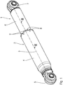
- the illustrated friction damper 1 has a two-part housing 2 with a longitudinal axis 3.
- the housing 2 has a first housing part 4, which is designed as an outer tube and to which a first fastening element 5 is attached. With the first fastening element 5, the friction damper 1 can be fastened to a component.
- the first housing part 4 is closed at the end facing the first fastening element 5.
- the first housing part 4 is open at the end opposite the first fastening element 5.
- a second housing part 6 in the form of an inner tube is inserted into the first housing part 4 through this opening.
- the second housing part 6 is closed at the end opposite the first housing part 4.
- a second fastening element 7 is provided, with which the friction damper 1 can be fastened to a further component.
- the fastening elements 5, 7 are each designed, for example, as fastening eyes with inserted sleeves which are oriented transversely to the longitudinal axis 3.
- the housing parts 4, 6 can be displaced relative to one another along the longitudinal axis 3.
- a guide element 8 is provided for the guided displacement of the second housing part 6.
- the housing parts 4, 6 are each designed as cylinder tubes.
- the housing parts 4, 6 have a non-circular contour in a plane perpendicular to the longitudinal axis 3.
- the housing parts 4, 6 can be designed as square tubes, rectangular tubes or oval tubes. In such an embodiment, a rotation of the housing parts 4, 6 with respect to the longitudinal axis 3 is prevented by positive locking.
- the friction damper 1 also has a pull-out protection which prevents the second housing part 6 from being accidentally pulled far out of the first housing part 4.
- the pull-out protection is ensured by the fact that the first housing part 4 is provided with radially inwardly projecting molded elements 9 which are arranged along a circular line around the longitudinal axis 3.
- the shaped elements 9 engage behind the guide element 8 in the interior of the first housing part 4.
- the guide element 8 is fixed axially and radially on the first housing part 4 with respect to the longitudinal axis 3.
- the guide element 8 protrudes in the radial direction with respect to the longitudinal axis 3 on the first housing part 4 inwards.
- a friction device 10 is attached to the second housing part 6, that is to say to the inner tube.
- the friction device 10 comprises a friction lining carrier 11, an adjustable friction lining 12 arranged on the friction lining carrier 11 and an adjusting element 13 for the adjustable arrangement of the friction lining 12 on the friction lining carrier 11.
- the friction device 10 is along the axial direction of the longitudinal axis 3 and with respect to a rotation about the longitudinal axis 3 fixed on the second housing part 6.
- the friction device 10 is fastened to the second housing part 6 by means of an indentation 14 on the inner tube for clamping the friction lining carrier 11.
- the friction device 10 projects in the radial direction with respect to the longitudinal axis 3 on the second housing part 6.
- the guide element 8 forms a pull-out stop for the second housing part 6 in that the friction device 10, in particular the friction lining carrier 11, is prevented from moving axially by the guide element 8 with a radially projecting annular shoulder 17.
- the friction lining carrier 11 is made in one piece, for example from plastic.
- the friction lining carrier 11 is essentially hollow-cylindrical with a peg-like anchoring section 15, with which the friction lining carrier 11 is inserted at the end into the inner tube of the second housing part 6.
- the anchoring section 15 has a circumferential inner groove 16, in which the indentation 14 engages around the To hold the friction lining carrier 11 on the second housing part 6.
- the friction lining carrier 11 has a first outer diameter D 1 , which essentially corresponds to the inner diameter of the inner tube of the second housing part 6.
- the friction lining carrier 11 has the radially projecting annular shoulder 17 adjoining the anchoring section 15, by means of which the friction lining carrier 11 rests on an annular end face of the second housing part 6.
- the friction lining carrier 11 is axially supported with the annular shoulder 17 on the inner tube of the second housing part 6.
- the ring shoulder 17 adjoins a carrier section 18 along an axial direction.
- the carrier section 18 has a second outer diameter D 2 that is larger than the first outer diameter D 1 .
- the second outer diameter D 2 essentially corresponds to the inner diameter of the outer tube of the first housing part 4.
- the carrier section 18 has several, in particular at least one and, according to the exemplary embodiment shown, exactly four, window-like radial recesses 19 along the outer circumference. Two adjacent radial recesses 19 are each separated from one another by an axial web 20.
- the friction lining carrier 11 On the face side, the friction lining carrier 11 has an annular web 32 in the region of the carrier section 18.
- the friction lining carrier 11 has a through hole 21 along an axial direction.
- the through hole 21 is designed in the region of the anchoring section 15 with an adjustment link 22 as a movement thread.
- the through hole 21 is designed as a frustoconical support section 23.
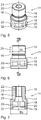
- the adjusting element 13 has an adjusting pin 24.
- the adjusting pin 24 has an external thread which corresponds to the internal thread of the adjusting link 22.
- the adjusting element 13 can be adjustably arranged with the adjusting pin 24 on the adjusting link 22 of the friction lining carrier 11 along an adjusting direction 25.
- the adjustment direction 25 corresponds to an axial direction of the friction lining carrier 11.
- the friction device 10 is arranged in the friction damper 1 such that the adjustment direction 25 is oriented to the longitudinal axis 3.
- a pressing section 26 is provided adjacent to the adjusting pin 24 and, starting from the adjusting pin 24, has a conically widening contour.
- the adjusting element 13 has a contact element 27 with which the adjusting element 13 can bear against the friction lining carrier 11 at the end to limit the adjustment.
- An actuating section 28 is provided on the end face of the contact element 27, which is designed as an eccentrically arranged slot-like depression.
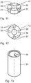
- the friction lining 12 is essentially in the form of an annular disk with a central, circular opening 29 through which the adjusting element 13 can be guided.
- a plurality of radially inwardly projecting recesses 30 are provided on the friction lining 12, by means of which the friction lining 12 can be fixed to the axial webs 20 of the friction lining carrier 11. This is an anti-twist protection for the Guaranteed friction lining 12 in the friction lining carrier 11.
- the friction lining 12 has radially protruding friction lining sections 31 between the recesses 30.
- the geometry of the friction lining sections 31 essentially corresponds to the size of the opening of the radial recesses 19 on the friction lining carrier 11.
- the friction lining 12 can be arranged in the friction lining carrier 11, in particular within the carrier section 18, in such a way that the friction lining sections 31 project outward in the radial direction through the radial recesses 19. Due to the axial webs 20 engaging in the recesses 30, the friction lining 12 is radially fixed in a direction of rotation about the longitudinal axis 3. The friction lining 12 is fixed to the friction lining carrier 11 along the axial direction by means of the circumferential annular web 32 on the end face, which is engaged behind by the friction lining sections 31.
- the actuating element 33 is essentially hollow-cylindrical and has an actuating counter-section 34 on the end face, which according to the exemplary embodiment shown is designed as a raised radial projection arranged eccentrically with respect to the longitudinal axis 3.
- the actuating counter section 34 is designed to correspond to the actuating section 28. It is essential that the interaction of the actuating section 28 with the actuating counter section 34 enables the adjusting element 13 to be connected to the actuating element 33 in a torque-transmitting manner about the longitudinal axis 3. In particular, there is a form fit between the adjusting element 13 and the actuating element 33.
- the respective contour of the actuating section 28 and the actuating counter section 34 is made non-circular in a plane perpendicular to the longitudinal axis 3.
- an external or internal polygonal contour is also conceivable, in particular a square or hexagonal contour.
- the actuating element 33 can be integrated in the first housing part 4 and can be fastened, for example, to the first fastening element 5.
- non-positive connection in particular frictional connection, can additionally or alternatively also serve.
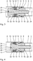
- the function of the friction damper is shown below Fig. 3 explained in more detail.
- the friction device 10 is held in the inner tube 6 with the friction lining carrier 11.
- the friction lining 12 is inserted in the carrier section 18 of the friction lining carrier 11, so that the friction lining sections 31 are arranged in the radial recesses 19.
- the adjusting element 13 is guided with the adjusting pin 24 through the opening 29 of the friction lining 12 and screwed in with the external thread on the adjusting link 22 of the friction lining carrier 11.
- the outer diameter of the adjusting pin 24 is smaller than the inner diameter of the opening 29. As long as the adjusting element 13 is screwed into the friction lining carrier 11 to such an extent that only the adjusting pin 24 is arranged within the opening 29, there is a radial expansion of the friction lining 12 not instead.
- the friction lining 12 is subjected to a radially outward pressing force.
- the contact pressure causes compression of the material from which the friction lining 12 is made.
- the friction lining sections 31 are pressed radially outward by the radial recesses 19 as a result of the pressing force.
- the friction lining 12 is pressed directly against an inner side 35 of the first housing part 4, that is to say the outer tube.
- a force results when the housing parts 4, 6 are displaced relative to one another along the longitudinal axis 3.
- FIG. 4 Such an arrangement is in Fig. 4 shown.
- the adjusting element 13 is screwed deep into the friction lining carrier 11.
- the adjusting element 13 rests with the contact element 27 on the end face against the annular web 32 of the friction lining carrier 11.
- a further axial displacement of the adjusting element 13 along the longitudinal axis 3 is prevented.
- a further axial displacement is also prevented by the adjusting element 13 resting with the pressing section 26 on the supporting section 23.
- the support of the adjusting element 13 on the friction lining carrier 11 is robust.
- a maximum screw-in depth is stably defined.
- a further, non-adjustable friction lining 36 is arranged on the friction lining carrier 11a.
- the friction lining carrier 11a has a circumferential inner groove 37.
- the non-adjustable friction lining 36 causes an unchangeable basic friction.
- the non-adjustable friction lining 36 projects radially from the friction lining carrier 11a in the region of the carrier section 18a.
- the inner groove 37 is part of the carrier section 18a.
- Another difference between the friction device 10a according to the second exemplary embodiment is that a plurality of individual friction linings 12a are provided. According to the exemplary embodiment shown, four individual, separate friction linings 12a are provided, for example.
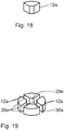
- the friction linings 12a can be positioned in relation to one another in such a way that the arrangement essentially corresponds to the shape of the friction lining 12 according to the first exemplary embodiment.
- the friction linings 12a essentially correspond to a circular disk segment with an opening angle of, for example, 90 °.
- the single friction pads 12a can be arranged to form a disk contour in such a way that they represent a substantially disk-shaped overall shape with opening 29a and recesses 30a.
- the individual friction linings 12a can be arranged radially protruding through the window-like radial recesses 19 by means of the adjusting element 13 and radially protruding.
- the setting of the friction damping that is to say the radially oriented frictional force acting on the inside 35, can be set directly and continuously adjustable by the screwing depth of the adjusting element 13 on the friction lining carrier 11.
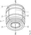
- an assembly 38 known as an expanding piston has at least one adjusting element 13b, by means of which the friction lining 12b can be displaced radially with respect to the longitudinal axis 3.
- the friction lining 12b is not acted upon directly by the at least one adjusting element 13b.
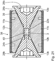
- the adjusting element 13b has a pressure carrier element 39 which can be displaced radially. Due to the radial displacement of the pressure carrier element 39, the friction lining 12b is against the inside of the housing 2 of the friction damper 1 pressed. The friction force changes depending on the contact pressure of the friction lining 12b.
- two oppositely arranged adjustment elements 13b are provided along the longitudinal axis 3, which can be displaced towards or away from one another by means of a movement thread along the longitudinal axis 3.
- the adjusting elements 13b each have an actuating element 28b on the end face in the form of an internal hexagon contour.
- the adjusting elements 13b each have a conical pressing section 26b, which interacts with the friction lining carriers 11b which cooperate therewith.
- the friction lining carriers are segmented in a circumferential direction about the longitudinal axis 3.
- Four friction lining carriers 11b are arranged along the outer circumference about the longitudinal axis 3.
- the friction lining carriers 11b can be displaced relative to one another. In particular, the friction lining carriers 11b are not directly connected to one another.
- a friction lining 12b is held on the outer cylinder jacket surface on the respective friction lining carrier 11b, in particular fastened, for example glued.
- Each individual friction lining 12b is displaced radially outwards with the radial displacement of the respective friction lining carrier 11b.
- a one-piece friction lining 12b on the outside of the expansion piston. Due to the radial displacement of the friction lining carrier 11b, the one-piece friction lining 12b is widened in the radial direction and thereby displaced and stretched radially outward. In addition, the friction lining 12b is pressed against the inside of the damper housing. In this embodiment, not shown in the figures, a uniform, homogeneous and continuous frictional force effect is made possible in the circumferential direction.
- the friction lining carriers 11b have, on an inner side opposite the friction linings 12b, respective pressing carrier element 39 interacting with the pressing section 26b. As a result of the axial displacement of the adjusting elements 13b arranged opposite one another, the friction lining carriers 11b are displaced radially outward with respect to the longitudinal axis 3.
- the adjustment elements 13b each have an adjustment end 24b with a thread on the end face, which engages in an adjustment link 22b with a corresponding mating thread for the adjustment movement along the longitudinal axis 3.
- the adjustment link 22b can be integrated in the adjustment element 13b arranged opposite. If only one adjustment element 13b is provided, the counter thread can be integrated in the inner housing part of the housing 2.
- An essential advantage of the expansion piston 38 is that the radial displacement of the pressure carrier element 39 towards the outside enables a uniform, in particular homogeneous, frictional force to be applied to the inside of the housing 2 of the friction damper 1, particularly along the circumference.
- the application of the friction force is in particular independent of the positional relationship of the friction device 10 in the friction damper 1.
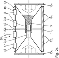
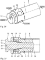
- the following will refer to 23 to 25 described a fourth embodiment of the invention. Structurally identical parts are given the same reference numerals as in the first three exemplary embodiments, to the description of which reference is hereby made. Structurally different, but functionally similar parts are given the same reference numerals with a c after them.
- the main difference compared to the previous exemplary embodiments is that the assembly 38c is designed as a longitudinally slotted sleeve.
- the longitudinally slotted sleeve 38c has a sleeve body which forms the friction lining carrier 11c.
- the friction lining carrier 11c has a longitudinal slot 41, in particular running parallel to the longitudinal axis 3.
- the assembly 38c has a structural flexibility in the circumferential direction about the longitudinal axis 3.
- Adjustment elements 13c which can be screwed into the face of the sleeve body as the friction lining carrier 11c bring about a radial expansion of the sleeve body and thus a radially adjustable pressing force on the friction linings 12c attached to the outside of the sleeve body.
- four separate, separate friction linings 12c are provided along the longitudinal axis 3.
- Each individual friction lining 12c is arranged as an elastic, circumferential friction ring on the outside of the sleeve body.
- the friction linings 12c are designed such that in an initial state they each have an inner diameter that is slightly smaller than the outer diameter of the sleeve body in the initial state.
- the friction linings 12c are arranged pretensioned on the outer surface of the sleeve body. An additional attachment of the friction linings 12c to the sleeve body is unnecessary.
- the manufacture of the sleeve body is straightforward and cost-effective.
- An expansion of the sleeve body is essentially not uniform along the circumferential direction. That means, that a comparatively increased elongation and spreading occurs in the region of the longitudinal slot 41. In this area, a higher contact force of the friction lining 12c on the inside of the housing 2 of the friction damper 1 is to be expected.
- the adjusting link 22c is integrated in the form of an internal thread, into which the adjusting elements 13c can be screwed, with a corresponding axial widening depending on the screwing depth of the adjusting elements 13c, i.e. their axial displacement along the longitudinal axis 3 the longitudinally slotted sleeve takes place by means of the pressing section 26.
- the friction linings 12c are arranged in a strip-like manner along a circumferential line about the longitudinal axis 3 on the sleeve body, in particular fastened there.
- the strip-like friction linings 12c have a slot 46, which is arranged in alignment with the longitudinal slot 41 of the sleeve body.
- the friction linings 12c each have clamp sections 47 facing away from one another, which are arranged on the sleeve body in an inwardly projecting manner and encompass the end faces of the longitudinal slot 41 of the sleeve body. With these clamp sections 47, the friction lining 12c is mechanically held on the sleeve body.
- a widening of the sleeve body with the adjusting elements 13c is unproblematic for the attachment of the friction lining 12c.
- repeated loading of the sleeve body by the at least one adjusting element 13c is unproblematic for the attachment of the friction lining 12c. Due to the mechanical fastening, in particular by positive locking, it is impossible for the friction lining 12c to detach from the sleeve body if an adhesive fastening is used fails. Additionally or alternatively, it is possible for the friction linings 12c to be glued to the sleeve body.
- the adjustment link 22c is held by means of flexible elements 42 between an inner wall of the sleeve body and an outer wall of the sleeve with the adjustment link.
- the flexible elements 42 can, for example, be elastic bands and / or an elastic washer to enable axial fixation along the longitudinal axis on the one hand and also the radial expansion, i.e. the variable distance in the radial direction between the inside of the sleeve and the outside of the body for to compensate for the adjustment.
- Fig. 26 and 27 described a fifth embodiment of the invention.
- Structurally identical parts are given the same reference numerals as in the previous exemplary embodiments, to the description of which reference is hereby made.
- Structurally different, but functionally similar parts are given the same reference numerals with a suffix d.
- the main difference compared to the previous exemplary embodiments is that the adjustment of the adjusting element 13d is motorized.
- a drive 43 in the form of an electric motor is provided, which is integrated in the second housing part 6.
- the drive 43 is held by means of fastening screws 44.
- the drive which can be designed with a gear, has an output shaft 45.
- the output shaft 45 serves to transmit torque to the adjusting element 13d.
- the output shaft 45 enables a linear displacement of the adjusting element 13d along the longitudinal axis 3. This is possible, for example, by the output shaft 45 being one with respect to the longitudinal axis 3 non-circular outer contour and the adjusting element 13d has a corresponding inner contour.
- the non-circular inner contour of the adjusting element 13d is a fastening element 28d.
- Such a contour can, for example, be square or hexagonal.
- the end face 27 of the adjusting element 13d is made flat.
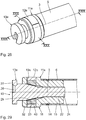
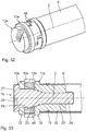
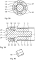
- the adjusting element 13e interacts directly with at least one displacement element, four displacement elements 46 according to the exemplary embodiment shown.
- the displacement elements 46 are designed in the shape of a ring segment.
- the shifting elements 46 In the circumferential direction around the longitudinal axis 3, the shifting elements 46 have an essentially S-shaped contour, with a central section and integrally formed on them, stretching sections extending circumferentially around the longitudinal axis 3, which are arranged along the circumferential direction around the longitudinal axis 3 such that the expansion sections of adjacent sliding elements interlock and a radial widening of the sliding elements 46 allow with respect to the longitudinal axis 3.
- the two expansion sections integrally formed on a central section are arranged offset with respect to the longitudinal axis 3 of the housing.
- the four displacement elements 46 are each identical. On its inside, which faces the adjustment element 13e, the displacement elements 46 are designed to correspond to the outer contour of the displacement element 13e.
- a displacement of the adjusting element 13e from the illustration according to Fig. 29 in the presentation according to Fig. 33 causes a radial displacement of the displacement elements 46 to the outside. While in the starting position according to Fig. 31 the expansion sections of the displacement elements 46 bear against one another both in the circumferential direction and in the longitudinal direction with respect to the longitudinal axis 3, the expansion sections of the displacement elements 46 in the radially expanded arrangement according to FIG Fig. 32 spaced from each other.
- the fact that a plurality of displacement elements 46, which are embodied separately from one another, provides radial expansion, that is to say their mobility relative to one another.
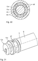
- the friction lining 12e is designed in one piece as a friction strip, which is folded around the displacement elements 46 in a ring.
- the two front ends of the friction strip, which are shown in Fig. 30 essentially abut one another and in particular face one another can be displaced relative to one another.
- the friction strip formed into the ring can be expanded.
- the friction strip has mobility, in particular in the circumferential direction about the longitudinal axis 3.
- the friction lining 12e is arranged such that it can be displaced in the circumferential direction with respect to the displacement elements 46.
- the friction lining 12e is made in particular of foam.
- the friction lining 12e lies with its outer Cylinder surface on the inside of the outer tube.
- the displacement elements 46 Due to the displacement of the adjusting element 13e, the displacement elements 46 are pushed radially outwards and the foam material of the friction lining 12e is thereby radially compressed. Since a radial shift to the outside is not possible, the friction strip is compressed, so that the clean power is increased.
- the friction lining 12e can also be designed as a closed friction ring, for example by connecting the two front ends of the friction strip to one another, for example by gluing them to one another. The friction lining is then designed as a closed friction ring.
- the friction lining 12e can also be made in several parts and in particular can be attached to one of the displacement elements 46.
- the main advantage of the embodiment according to the sixth embodiment is that the height of the friction lining is reduced by the use of the adjusting elements 46.
- a reduced adjustment path of the adjustment element 13e is sufficient.
- fewer revolutions of the adjusting element 13e are required. It has been found that the friction effect with the friction lining 12e, which has a smaller friction lining expansion in the radial direction with respect to the longitudinal axis 3, is greater than with a friction lining 12e with a large radial thickness.
- the displacement elements 46f are arranged in a window-like radial recess 19f of the friction lining carrier 11f and are arranged such that they can be displaced in the radial direction with respect to the longitudinal axis 3.
- the displacement elements 46f are displaced radially along the radial recess 19f.
- the displacement elements 46f and the friction linings 12f arranged thereon, in particular fastened thereon, are fixed to the friction lining carrier 11f both in the circumferential direction about the longitudinal axis 3 and in the axial direction of the longitudinal axis 3.
- the friction lining carrier 1 1 f has four radial recesses 19 f. It goes without saying that more or less than four radial recesses can also be provided.
Description
Die Erfindung betrifft eine Reibungsvorrichtung für einen Reibungsdämpfer sowie einen Reibungsdämpfer mit einer derartigen Reibungsvorrichtung.The invention relates to a friction device for a friction damper and a friction damper with such a friction device.
Reibungsdämpfer sind für die Erzeugung einer Reibungsdämpfung zwischen zwei beweglich verbundenen Bauteilen beispielsweise aus
Der Erfindung liegt die Aufgabe zugrunde, die Funktionalität eines Reibungsdämpfers zu verbessern.The invention has for its object to improve the functionality of a friction damper.
Die Aufgabe wird durch die Merkmale der Ansprüche 1 und 11 gelöst. Der Kern der Erfindung besteht darin, dass eine mit einem Reibungsdämpfer erzielbare Reibungswirkung veränderlich, insbesondere gezielt veränderlich, einstellbar ist. Insbesondere kann eine Reibungskraft, die mittels einer Reibungsvorrichtung zur Erzielung der Reibungswirkung ausübbar ist, gezielt eingestellt werden. Insbesondere ist die veränderliche Einstellbarkeit der Reibungswirkung unmittelbar und unkompliziert möglich. Der Krafteinstellbare Reibungsdämpfer mit einer derartigen Reibungsvorrichtung ist flexibel einsetzbar und ermöglicht insbesondere die Anwendung in einem Produkt, das unterschiedlich, insbesondere bedarfsbedingt, einstellbare Reibungswirkungen aufweisen soll. Ein derartiger Reibungsdämpfer ist beispielsweise vorteilhaft in Waschgeräten einsetzbar. Als Ersatzteil wäre ein einziger erfindungsgemäßer Kraft-einstellbarer Reibungsdämpfer ausreichend, der je nach Einsatzzweck in dem Waschgerät mit der erforderlichen Reibungskraft eingestellt werden kann. Im Sondermaschinenbau kann ein Reibungsdämpfer zur Schwingungsdämpfung eingesetzt werden, wobei die Reibungswirkung individuell an die tatsächlichen Schwingungsverhältnisse in der Maschine angepasst und eingestellt werden kann. Der erfindungsgemäße Reibungsdämpfer ist auch in Fitnessgeräten einsetzbar. Durch die Veränderung der Reibungswirkung kann die dadurch verursachte Gegenkraft gezielt verändert werden. Die Reibungsvorrichtung umfasst einen Reibbelagsträger, mindestens einen an dem Reibbelagsträger angeordneten verstellbaren Reibbelag sowie ein Verstellelement zum verstellbaren Anordnen des mindestens einen Reibbelags an dem Reibbelagsträger. Durch die Verstellung des mindestens einen Reibbelags wird die resultierende Reibungswirkung verändert. Der Reibbelagsträger ist insbesondere einteilig ausgeführt. Der mindestens eine Reibbelag ist an dem Reibbelagsträger bezüglich der Längsachse des Gehäuses fixiert. Insbesondere ist der mindestens eine Reibbelag an dem Reibbelagsträger bezüglich der Längsachse in axialer Richtung und/oder in Umfangsrichtung um die Längsachse fixiert. Es ist auch denkbar, dass der Reibbelag an dem Reibbelagsträger ausschließlich in axialer Richtung bezüglich der Längsachse festgelegt ist und insbesondere in Umfangsrichtung um die Längsachse nicht festgelegt, insbesondere verlagerbar ist.The object is achieved by the features of
Eine fensterartige Radialausnehmung des Reibbelagsträgers für den mindestens einen verstellbaren Reibbelag ermöglicht eine unkomplizierte Radialverlagerung des Reibbelags. Die Reibkraftaufbringung ist vereinfacht.A window-like radial recess of the friction lining carrier for the at least one adjustable friction lining enables an uncomplicated radial displacement of the friction lining. The application of friction is simplified.
Eine Verstellkulisse, mittels der das Verstellelement relativ zum Reibbelagsträger und entlang einer Verstellrichtung verstellbar angeordnet ist, ermöglicht eine unkomplizierte und unmittelbare Verstellung des Verstellelements relativ zum Reibbelagsträger. Die Verstellung des Verstellelements kann manuell und/oder motorisch, insbesondere elektromotorisch, erfolgen. Die Verstellkulisse ist insbesondere als Bewegungsgewinde ausgeführt, das insbesondere eine kontinuierliche Verstellung ermöglicht. Es ist alternativ denkbar, eine Verstellung mittels einer Rastgeometrie mit mehreren direkten Raststufen auszuführen. In diesem Fall weist die Verstellkulisse mehrere diskontinuierliche, also voneinander getrennte, Verstellstufen auf. Die Verstellung zwischen zwei Verstellstufen erfolgt diskontinuierlich.An adjustment link, by means of which the adjustment element is arranged to be adjustable relative to the friction lining carrier and along an adjustment direction, enables an uncomplicated and direct adjustment of the adjustment element relative to the friction lining carrier. The adjustment element can be adjusted manually and / or by motor, in particular by an electric motor. The adjustment link is designed in particular as a movement thread, which in particular enables continuous adjustment. Alternatively, it is conceivable to carry out an adjustment by means of a locking geometry with several direct locking stages. In this case, the adjustment link has several discontinuous, ie separate, adjustment stages. The adjustment between two adjustment levels is discontinuous.
Das Verstellelement kann unmittelbar mit dem Reibbelag zusammenwirken, indem der Reibbelag durch das Verstellelement verdrängt wird. Der Reibbelag, der insbesondere aus einem komprimierbaren Material besteht, wird zumindest anteilig komprimiert und dadurch radial nach außen gedrückt.The adjusting element can interact directly with the friction lining by displacing the friction lining through the adjusting element. The friction lining, which consists in particular of a compressible material, is at least partially compressed and thereby pressed radially outwards.
Zusätzlich oder alternativ ist es möglich, ein Anpressträgerelement vorzusehen, das unmittelbar mit dem Verstellelement zusammenwirkt. Das Verstellelement bewirkt eine Verlagerung des Anpressträgerelements, an dem der Reibbelag gehalten ist. Das Anpressträgerelement wird insbesondere ausschließlich radial bezüglich einer Längsachse verlagert. Das Anpressträgerelement ist Teil eines sogenannten Spreizkolbens, bei dem scheiben- oder hülsenförmige Segmentabschnitte eines Hohlzylinders bezüglich der Zylinderachse radial verlagert werden. Die Segmentabschnitte sind, insbesondere bezüglich des Reibbelags, der an der Außenseite der jeweiligen Verstellelemente angebracht ist, aus einem starren Material hergestellt. Starr bedeutet, dass die einzelnen Segmentabschnitte sich nicht deformieren. Die Segmentabschnitte sind aus einem Material hergestellt, das eine Steifigkeit und/oder Festigkeit aufweist, die größer ist als die des Materials des Reibbelags. Die Segmentabschnitte werden durch das Zusammenwirken mit dem Verstellelement bezüglich der Längsachse strahlenförmig nach außen verlagert, wodurch sich der Außendurchmesser des Anpressträgerelements, das von den Segmentabschnitten gebildet ist, vergrößert.Additionally or alternatively, it is possible to provide a pressure carrier element which interacts directly with the adjusting element. The adjusting element causes a displacement of the pressure carrier element on which the friction lining is held. The contact carrier element is in particular displaced exclusively radially with respect to a longitudinal axis. The pressure carrier element is part of a so-called expansion piston, in which disk-shaped or sleeve-shaped segment sections of a hollow cylinder are displaced radially with respect to the cylinder axis. The segment sections, in particular with regard to the friction lining, are on the outside of the respective Adjusting elements is attached, made of a rigid material. Rigid means that the individual segment sections do not deform. The segment sections are made of a material that has a stiffness and / or strength that is greater than that of the material of the friction lining. The segment sections are radially displaced outwards with respect to the longitudinal axis due to the interaction with the adjusting element, as a result of which the outer diameter of the pressure carrier element, which is formed by the segment sections, increases.
Das Anpressträgerelement kann Teil einer längsgeschlitzten Hülse sein. In diesem Fall bewirkt das Verstellelement eine Aufweitung des Anpressträgerelements in Umfangsrichtung um die Längsachse. Das Anpressträgerelement wird zumindest anteilig elastisch deformiert. Der Betrag der Aufweitung ist entlang der Umfangsrichtung inhomogen. Im Bereich des Schlitzes ist die Aufweitung vergleichsweise groß, insbesondere maximal. Die Hülse ist insbesondere dünnwandig ausgeführt. Das bedeutet, dass das Verhältnis von Wandstärke zu Durchmesser der Hülse kleiner ist als 0,1, insbesondere kleiner als 0,05, insbesondere kleiner als 0,01 und insbesondere kleiner als 0,005. Die längsgeschlitzte Hülse weist eine Strukturflexibilität auf, die ein Aufweiten der Hülse in Umfangsrichtung ermöglicht.The pressing element can be part of a longitudinally slotted sleeve. In this case, the adjusting element causes the pressure carrier element to widen in the circumferential direction about the longitudinal axis. The contact element is at least partially elastically deformed. The amount of expansion is inhomogeneous along the circumferential direction. The widening in the area of the slot is comparatively large, in particular maximal. The sleeve is particularly thin-walled. This means that the ratio of wall thickness to diameter of the sleeve is less than 0.1, in particular less than 0.05, in particular less than 0.01 and in particular less than 0.005. The longitudinally slotted sleeve has a structural flexibility that enables the sleeve to be expanded in the circumferential direction.
Die Verlagerung des Reibbelags erfolgt mittelbar durch die Verlagerung des Anpressträgerelements. Der Reibbelag wird durch das Verstellelement also nicht unmittelbar komprimiert, sondern verschoben bzw. verlagert. Der Reibbelag kann infolge der Verlagerung mittelbar komprimiert werden, indem der Reibbelag gegen die Innenseite des Dämpfergehäuses gedrückt wird und/oder indem der Reibbelag beispielsweise infolge der Aufweitung in Umfangsrichtung an der Spreizhülse in Umfangsrichtung gedehnt und damit in Dickenrichtung komprimiert wird.The friction lining is displaced indirectly by the displacement of the contact element. The friction lining is therefore not directly compressed by the adjusting element, but rather shifted or shifted. The friction lining can be compressed indirectly as a result of the displacement by pressing the friction lining against the inside of the damper housing and / or by the friction lining being stretched in the circumferential direction, for example as a result of the widening in the circumferential direction, and thus being compressed in the thickness direction.
Ein Anpressabschnitt gemäß Anspruch 2 ermöglicht das unmittelbare Aufbringen einer Anpresskraft von dem Verstellelement auf den Reibbelag. Insbesondere weist der Anpressabschnitt entlang einer Verstellrichtung eine zumindest abschnittsweise veränderlich ausgeführte Kontur auf. Die Kontur kann beispielsweise linear, progressiv oder degressiv verlaufen. Es ist auch denkbar, diese verschiedenartigen Verläufe abschnittsweise miteinander zu kombinieren und insbesondere abschnittsweise eine unveränderliche Kontur vorzusehen. Beispielsweise kann die Kontur einen zunächst progressiven Verlauf aufweisen, dem sich ein linearer Verlauf und/oder ein degressiver Verlauf anschließen. Es ist auch eine andere Kombination möglich. Der Anpressabschnitt wirkt passiv, indem die Verlagerung des Verstellelements zum Reibbelagsträger unmittelbar eine Verstellung des Reibbelags relativ zum Reibbelagsträger bewirkt. Durch die Anpresskraft wird der Reibbelag zumindest teilweise verlagert. Dadurch, dass der Reibbelag insbesondere aus einem kompressiblen Material, insbesondere aus einem geschäumten Kunststoff, hergestellt ist, bewirkt die Anpresskraft auch zumindest anteilig eine Kompression des Reibbelags.A pressing section according to
Alternativ ist es möglich, dass die Anpresskraft auf den mindestens einen verstellbaren Reibbelag mittelbar aufgebracht wird. Der mindestens eine verstellbare Reibbelag kann an einem Anpressträgerelement befestigt sein, wobei das Anpressträgerelement von dem Anpressabschnitt mit der Anpresskraft beaufschlagt wird. Ein derartiges Verstellelement mit Anpressträgerelementen ist beispielsweise ein Spreizkolben oder eine längs, also axial, geschlitzte Hülse.Alternatively, it is possible for the contact pressure to be applied indirectly to the at least one adjustable friction lining. The at least one adjustable friction lining can be fastened to a pressure carrier element, the pressure carrier element being acted upon by the pressure force from the pressure section. Such an adjustment element with pressure carrier elements is, for example, an expansion piston or a longitudinally, ie axially, slotted sleeve.
Wesentlich ist, dass das Verstellelement mit dem Anpressabschnitt geeignet ist, die, insbesondere axiale, Verstellbewegung in eine, insbesondere radial gerichtete, Anpressbewegung umzusetzen. Der Reibbelag wird dadurch radial vorgespannt.It is essential that the adjusting element with the pressing section is suitable for the, in particular axial, adjusting movement in one, in particular to implement radially directed pressing movement. The radial friction is thereby preloaded.
Alternativ ist es möglich, den Anpressabschnitt mit mindestens einem aktiv betätigbaren Anpresselement auszuführen. Ein aktives Anpresselement kann beispielsweise als relativ zum Verstellelement, insbesondere radial nach außen verlagerbares Element, ausgeführt sein, um eine aktive Verstellbewegung über eine entsprechende Kinematikvorrichtung von dem Verstellelement auf das Anpresselement zum Anpressen des Reibbelags auszuüben. Für die aktive Verstellbewegung kann die Kinematikvorrichtung mindestens ein Kraftspeicherelement, beispielsweise ein Federelement, und/oder einen Aktuator aufweisen. Die aktive Verstellbewegung kann manuell und/oder motorisch erfolgen.Alternatively, it is possible to design the pressing section with at least one actively actuating pressing element. An active pressure element can be designed, for example, as an element that can be displaced relative to the adjustment element, in particular radially outwards, in order to carry out an active adjustment movement from the adjustment element to the pressure element via a corresponding kinematic device for pressing the friction lining. For the active adjustment movement, the kinematic device can have at least one energy storage element, for example a spring element, and / or an actuator. The active adjustment movement can be done manually and / or by motor.
Eine Ausführung des Anpressabschnitts gemäß Anspruch 3 ermöglicht eine vorteilhafte Beaufschlagung des Reibbelags mit der Anpresskraft. Insbesondere ist es unkompliziert möglich, eine lineare, insbesondere axiale Verstellbewegung in eine vollumfänglich wirkende, radiale Anpressbewegung zu übersetzen.An embodiment of the pressing section according to
Ein Betätigungsabschnitt gemäß Anspruch 4 vereinfacht eine unmittelbare Betätigung des Verstellelements. Der Betätigungsabschnitt kann als schlitzförmige Vertiefung ausgeführt sein, die mittels eines entsprechenden Gegenelementes beaufschlagt werden kann.An actuating section according to
Ein Betätigungselement gemäß Anspruch 5 vereinfacht ein unmittelbares Betätigen des Verstellelements. Das Betätigungselement weist insbesondere einen Betätigungsgegenabschnitt auf, der mit dem Betätigungsabschnitt am Verstellelement korrespondiert. Insbesondere ist der Betätigungsgegenabschnitt als stegartige Erhebung ausgeführt, die in die schlitzartige Vertiefung des Betätigungsabschnitts unmittelbar eingreifen kann. Das Betätigungselement ist insbesondere in dem Reibungsdämpfer integriert ausgeführt und kann beispielsweise über eine beispielsweise radiale Öffnung im Gehäuse des Reibungsdämpfers unmittelbar betätigt werden. Es ist auch möglich, das Betätigungselement beispielsweise an einem Befestigungselement des Reibungsdämpfers mechanisch zu koppeln, so dass das Betätigungselement über das Befestigungselement verstellbar ist.An actuating element according to claim 5 simplifies direct actuation of the adjusting element. The actuating element has, in particular, an actuating counter section which corresponds to the actuating section on the adjusting element. In particular, the actuating counter section designed as a web-like elevation that can engage directly in the slot-like depression of the actuating section. The actuating element is in particular designed to be integrated in the friction damper and can be actuated directly, for example, via a radial opening in the housing of the friction damper, for example. It is also possible to mechanically couple the actuating element, for example to a fastening element of the friction damper, so that the actuating element can be adjusted via the fastening element.
Ein ringförmiger Reibbelag gemäß Anspruch 6 ermöglicht eine vorteilhafte, insbesondere gleichmäßige und homogene Beaufschlagung mit der Anpresskraft durch das Verstellelement.An annular friction lining according to
Eine verdrehsichere Befestigung des Reibbelags am Reibbelagsträger gemäß Anspruch 8 gewährleistet eine zuverlässige Reibungswirkung, insbesondere wenn der Reibbelag durch das Verstellelement beaufschlagt wird. Eine unbeabsichtigte Verdrehung des Reibbelags in Folge einer Verdrehbewegung des Verstellelements ist ausgeschlossen.A non-rotatable fastening of the friction lining on the friction lining carrier according to
Ein zusätzlicher, unverstellbar angeordneter Reibbelag gemäß Anspruch 9 gewährleistet eine konstante Grundreibkraft unabhängig von der verstellbar festlegbaren Reibkraft des verstellbaren Reibbelags.An additional, non-adjustable friction lining according to
Ein Reibungsdämpfer gemäß Anspruch 10 mit der Reibungsvorrichtung weist die vorstehend erläuterten Vorteile auf, worauf hiermit verwiesen wird.A friction damper according to claim 10 with the friction device has the advantages explained above, to which reference is hereby made.
Ein Reibungsdämpfer gemäß Anspruch 11 ist unaufwändig konstruiert. Ein Gehäuse des Reibungsdämpfers ist im Wesentlichen zweigeteilt ausgeführt.A friction damper according to
Eine Ausführung des Reibungsdämpfers gemäß Anspruch 12 ermöglicht eine unmittelbare Axialverlagerung der Gehäuseteile zueinander.An embodiment of the friction damper according to
Ein Reibungsdämpfer gemäß Anspruch 13 ermöglicht eine unkomplizierte und unmittelbare Beaufschlagung mit der Reibungskraft.A friction damper according to
Die Anordnung der Reibungsvorrichtung gemäß Anspruch 14 ermöglicht eine intuitive und direkte Verstellung der Reibungswirkung.The arrangement of the friction device according to
Weitere vorteilhafte Ausgestaltungen, zusätzliche Merkmale und Einzelheiten der Erfindung ergeben sich aus der nachfolgenden Beschreibung von fünf Ausführungsbeispielen anhand der Zeichnung. Es zeigen:
- Fig. 1
- eine perspektivische Gesamtansicht eines erfindungsgemäßen Reibungsdämpfers mit einer erfindungsgemäßen Reibungsvorrichtung gemäß einem ersten Ausführungsbeispiel,
- Fig. 2
- eine
Fig. 1 entsprechende Teildarstellung des Reibungsdämpfers mit freigelegter Reibungsvorrichtung, - Fig. 3
- einen Längsschnitt gemäß der Schnittlinie III-III in
Fig. 1 zur Darstellung der Reibungsvorrichtung in einer ersten Verstellposition, - Fig. 4
- eine
Fig. 3 entsprechende Darstellung in einer zweiten, von der ersten Verstellposition verschiedenen Verstellposition, - Fig. 5
- eine vergrößerte perspektivische Darstellung eines Reibbelagsträgers der Reibungsvorrichtung in
Fig. 2 , - Fig. 6
- eine Seitenansicht des Verstellelements gemäß
Fig. 5 , - Fig. 7
- einen Längsschnitt gemäß der Schnittlinie VII-VII in
Fig. 6 , - Fig. 8
- eine vergrößerte Perspektivdarstellung eines Verstellelements der Reibungsvorrichtung gemäß
Fig. 2 , - Fig. 9
- eine Seitenansicht des Verstellelements gemäß
Fig. 8 , - Fig. 10
- eine Ansicht gemäß Pfeil X in
Fig. 9 , - Fig. 11
- eine perspektivische vergrößerte Detailansicht eines Reibbelags der Reibungsvorrichtung gemäß
Fig. 2 , - Fig. 12
- eine Draufsicht auf den Reibbelag gemäß
Fig. 11 , - Fig. 13
- ein Betätigungselement zum Betätigen des Verstellelements gemäß
Fig. 8 ,bis 10 - Fig. 14
- eine
Fig. 2 entsprechende Darstellung einer Reibungsvorrichtung gemäß einem zweiten Ausführungsbeispiel, - Fig. 15
- eine vergrößerte perspektivische Darstellung des Reibbelagsträgers der Reibungsvorrichtung gemäß
Fig. 14 , - Fig. 16
- eine Seitenansicht des Reibbelagsträgers gemäß
Fig. 15 , - Fig. 17
- einen Längsschnitt gemäß Schnittlinie XVII-XVII in
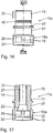
Fig. 16 , - Fig. 18
- eine perspektivische Darstellung eines einzelnen Reibbelags der Reibungsvorrichtung in
Fig. 14 , - Fig. 19
- eine Anordnung der einzelnen Reibbeläge gemäß
Fig. 18 einer Anordnung gemäß des Reibbelags des ersten Ausführungsbeispiels inFig. 11 , - Fig. 20
- eine perspektivische Darstellung eines Verstellelements gemäß einem dritten Ausführungsbeispiel,
- Fig. 21
- eine Schnittdarstellung gemäß Schnittlinie XXI-XXI in
Fig. 20 mit zusätzlich dargestellten Reibbelägen, - Fig. 22
- eine
Fig. 21 entsprechende Darstellung des Verstellelements mit radial nach außen verlagerten Reibbelägen, - Fig. 23
- eine perspektivische Darstellung eines Verstellelements gemäß einem vierten Ausführungsbeispiel,
- Fig. 24
- einen Längsschnitt gemäß Schnittlinie XXIV-XXIV in
Fig. 23 , - Fig. 25
- eine
Fig. 24 entsprechende Darstellung des Verstellelements mit radial verlagerten Reibbelägen, - Fig. 26
- eine
Fig. 2 entsprechende Teildarstellung einer Reibungsvorrichtung gemäß einem fünften Ausführungsbeispiel, - Fig. 27
- einen Längsschnitt des Reibungsdämpfers mit der Reibungsvorrichtung gemäß
Fig. 26 , - Fig. 28
- eine
Fig. 2 entsprechende Teildarstellung einer Reibungsvorrichtung gemäß einem sechsten Ausführungsbeispiel, - Fig. 29
- einen Längsschnitt gemäß Schnittlinie XXIX- XXIX in
Fig. 28 , - Fig. 30
- einen Querschnitt gemäß Schnittlinie XXX- XXX in
Fig. 28 , - Fig. 31
- eine
Fig. 28 entsprechende perspektivische Darstellung, wobei zur Darstellung von Schiebelementen der Reibbelag nicht gezeigt ist, - Fig. 32
- eine
Fig. 31 entsprechende Darstellung mit radial nach außen verlagerten Verschiebeelementen, - Fig. 33
- eine
Fig. 29 entsprechende Schnittdarstellung mit radial verschobenen Verschiebeelementen, - Fig. 34
- eine
Fig. 30 entsprechende Schnittdarstellung mit radial nach außen verlagerten Verschiebeelementen, - Fig. 35
- eine vergrößerte Perspektivdarstellung eines Verschiebeelements gemäß
Fig. 32 , - Fig. 36
- eine
Fig. 2 entsprechende Teildarstellung einer Reibungsvorrichtung gemäß einem siebten Ausführungsbeispiel, - Fig. 37
- eine Schnittdarstellung gemäß Schnittlinie XXXVII-XXXVII in
Fig. 36 , - Fig. 38
- eine Schnittdarstellung gemäß Schnittlinie XXXVIII-XXXVIII in
Fig. 36 , - Fig. 39
- eine
Fig. 37 entsprechende Darstellung mit radial nach außen verlagerten Verschiebelementen, - Fig. 40
- eine vergrößerte Detaildarstellung eines Verschiebeelements gemäß
Fig. 37 .
- Fig. 1
- 1 shows an overall perspective view of a friction damper according to the invention with a friction device according to the invention according to a first exemplary embodiment,
- Fig. 2
- a
Fig. 1 corresponding partial representation of the friction damper with the friction device exposed, - Fig. 3
- a longitudinal section along the section line III-III in
Fig. 1 to represent the friction device in a first adjustment position, - Fig. 4
- a
Fig. 3 corresponding representation in a second adjustment position different from the first adjustment position, - Fig. 5
- an enlarged perspective view of a friction lining of the friction device in
Fig. 2 , - Fig. 6
- a side view of the adjusting element according to
Fig. 5 , - Fig. 7
- a longitudinal section along the section line VII-VII in
Fig. 6 , - Fig. 8
- an enlarged perspective view of an adjusting element of the friction device according to
Fig. 2 , - Fig. 9
- a side view of the adjusting element according to
Fig. 8 , - Fig. 10
- a view according to arrow X in
Fig. 9 , - Fig. 11
- a perspective enlarged detail view of a friction lining of the friction device according to
Fig. 2 , - Fig. 12
- a top view of the friction lining according
Fig. 11 , - Fig. 13
- an actuating element for actuating the adjusting element according to
8 to 10 , - Fig. 14
- a
Fig. 2 corresponding representation of a friction device according to a second embodiment, - Fig. 15
- an enlarged perspective view of the friction lining of the friction device according to
Fig. 14 , - Fig. 16
- a side view of the friction lining according to
Fig. 15 , - Fig. 17
- a longitudinal section along section line XVII-XVII in
Fig. 16 , - Fig. 18
- a perspective view of a single friction lining of the friction device in
Fig. 14 , - Fig. 19
- an arrangement of the individual friction linings
Fig. 18 an arrangement according to the friction lining of the first embodiment inFig. 11 , - Fig. 20
- 2 shows a perspective illustration of an adjusting element according to a third exemplary embodiment,
- Fig. 21
- a sectional view along section line XXI-XXI in
Fig. 20 with additionally shown friction linings, - Fig. 22
- a
Fig. 21 corresponding representation of the adjusting element with radially outwardly displaced friction linings, - Fig. 23
- 2 shows a perspective illustration of an adjusting element according to a fourth exemplary embodiment,
- Fig. 24
- a longitudinal section along section line XXIV-XXIV in
Fig. 23 , - Fig. 25
- a
Fig. 24 corresponding representation of the adjusting element with radially displaced friction linings, - Fig. 26
- a
Fig. 2 corresponding partial representation of a friction device according to a fifth exemplary embodiment, - Fig. 27
- a longitudinal section of the friction damper with the friction device according to
Fig. 26 , - Fig. 28
- a
Fig. 2 corresponding partial representation of a friction device according to a sixth embodiment, - Fig. 29
- a longitudinal section along section line XXIX-XXIX in
Fig. 28 , - Fig. 30
- a cross section along section line XXX-XXX in
Fig. 28 , - Fig. 31
- a
Fig. 28 Corresponding perspective representation, the friction lining not being shown to represent sliding elements, - Fig. 32
- a
Fig. 31 corresponding representation with displacement elements displaced radially outwards, - Fig. 33
- a
Fig. 29 corresponding sectional view with radially displaced displacement elements, - Fig. 34
- a
Fig. 30 corresponding sectional view with displacement elements displaced radially outwards, - Fig. 35
- an enlarged perspective view of a sliding element according to
Fig. 32 , - Fig. 36
- a
Fig. 2 corresponding partial representation of a friction device according to a seventh exemplary embodiment, - Fig. 37
- a sectional view along section line XXXVII-XXXVII in
Fig. 36 , - Fig. 38
- a sectional view along section line XXXVIII-XXXVIII in
Fig. 36 , - Fig. 39
- a
Fig. 37 corresponding representation with displacement elements displaced radially outwards, - Fig. 40
- an enlarged detail view of a displacement element according to
Fig. 37 .
Ein in den
Das Gehäuse 2 weist ein erstes Gehäuseteil 4 auf, das als Außenrohr ausgeführt ist und an dem ein erstes Befestigungselement 5 angebracht ist. Mit dem ersten Befestigungselement 5 kann der Reibungsdämpfer 1 an einer Komponente befestigt werden. An dem dem ersten Befestigungselement 5 zugewandten Ende ist das erste Gehäuseteil 4 verschlossen. An dem dem ersten Befestigungselement 5 gegenüberliegenden Ende ist das erste Gehäuseteil 4 geöffnet. Durch diese Öffnung ist ein zweites Gehäuseteil 6 in Form eines Innenrohrs in das erste Gehäuseteil 4 eingeführt.The
An dem dem ersten Gehäuseteil 4 gegenüberliegenden Ende ist das zweite Gehäuseteil 6 verschlossen. An dem verschlossenen Ende des zweiten Gehäuseteils 6 ist ein zweites Befestigungselement 7 vorgesehen, mit dem der Reibungsdämpfer 1 an einer weiteren Komponente befestigt werden kann. Die Befestigungselemente 5, 7 sind beispielsweise jeweils als Befestigungsaugen ausgeführt mit eingesteckten Hülsen, die quer zur Längsachse 3 orientiert sind. Die Gehäuseteile 4, 6 sind relativ zueinander entlang der Längsachse 3 verlagerbar. An dem geöffneten Ende des ersten Gehäuseteils 4 ist ein Führungselement 8 zur geführten Verlagerung des zweiten Gehäuseteils 6 vorgesehen.The
Gemäß dem gezeigten Ausführungsbeispiel sind die Gehäuseteile 4, 6 jeweils als Zylinderrohre ausgeführt. Es ist grundsätzlich auch denkbar, dass die Gehäuseteile 4, 6 in einer Ebene senkrecht zur Längsachse 3 eine unrunde Kontur aufweisen. Beispielsweise können die Gehäuseteile 4, 6 als Quadratrohre, Rechteckrohre oder Ovalrohre ausgeführt sein. Bei einer derartigen Ausführung ist eine Verdrehung der Gehäuseteile 4, 6 bezüglich der Längsachse 3 durch Formschluss verhindert.According to the exemplary embodiment shown, the
Der Reibungsdämpfer 1 weist ferner einen Ausziehschutz auf, der verhindert, dass das zweite Gehäuseteil 6 unbeabsichtigt weit aus dem ersten Gehäuseteil 4 herausgezogen wird. Gemäß dem gezeigten Ausführungsbeispiel ist der Ausziehschutz dadurch gewährleistet, dass an dem ersten gehäuseteil 4 radial nach innen vorstehende Formelemente 9 vorgesehen sind, die entlang einer Kreislinie um die Längsachse 3 angeordnet sind. Die Formelemente 9 hintergreifen das Führungselement 8 im Inneren des ersten Gehäuseteils 4. Das Führungselement 8 ist bezüglich der Längsachse 3 axial und radial am ersten Gehäuseteil 4 festgelegt. Das Führungselement 8 ragt in radialer Richtung bezüglich der Längsachse 3 an dem ersten Gehäuseteil 4 nach innen vor.The friction damper 1 also has a pull-out protection which prevents the
Gemäß dem gezeigten Ausführungsbeispiel ist an dem zweiten Gehäuseteil 6, also an dem Innenrohr, eine Reibungsvorrichtung 10 befestigt. Die Reibungsvorrichtung 10 umfasst einen Reibbelagsträger 11, einen an dem Reibbelagsträger 11 angeordneten verstellbaren Reibbelag 12 sowie ein Verstellelement 13 zum verstellbaren Anordnen des Reibbelags 12 am Reibbelagsträger 11. Die Reibungsvorrichtung 10 ist entlang der axialen Richtung der Längsachse 3 und bezüglich einer Drehung um die Längsachse 3 am zweiten Gehäuseteil 6 festgelegt. Gemäß dem gezeigten Ausführungsbeispiel ist die Befestigung der Reibungsvorrichtung 10 an dem zweiten Gehäuseteil 6 mittels einer Einprägung 14 am Innenrohr zur Klemmung des Reibbelagsträgers 11 ausgeführt.According to the exemplary embodiment shown, a
Die Reibungsvorrichtung 10 steht in radialer Richtung bezüglich der Längsachse 3 am zweiten Gehäuseteil 6 vor. Das Führungselement 8 bildet einen Ausziehstopp für das zweite Gehäuseteil 6, indem die Reibungsvorrichtung 10, insbesondere der Reibbelagsträger 11, mit einer radial vorstehenden Ringschulter 17 an einer Axialverlagerung durch das Führungselement 8 gehindert ist.The
Nachfolgend wird anhand von
Der Reibbelagsträger 11 weist die sich dem Verankerungsabschnitt 15 anschließende, radial vorstehende Ringschulter 17 auf, mit der der Reibbelagsträger 11 an einer ringförmigen Stirnseite des zweiten Gehäuseteils 6 anliegt. Der Reibbelagsträger 11 ist mit der Ringschulter 17 an dem Innenrohr des zweiten Gehäuseteils 6 axial abgestützt.The
Entlang einer axialen Richtung schließt sich der Ringschulter 17 ein Trägerabschnitt 18 an. Der Trägerabschnitt 18 weist einen zweiten Außendurchmesser D2 auf, der größer ist als der erste Außendurchmesser D1. Der zweite Außendurchmesser D2 entspricht im Wesentlichen dem Innendurchmesser des Außenrohrs des ersten Gehäuseteils 4. Der Trägerabschnitt 18 weist entlang des äußeren Umfangs mehrere, insbesondere mindestens eine und gemäß dem gezeigten Ausführungsbeispiel genau vier, fensterartige Radialausnehmungen 19 auf. Zwei benachbarte Radialausnehmungen 19 sind jeweils durch einen Axialsteg 20 voneinander getrennt. Stirnseitig weist der Reibbelagsträger 11 im Bereich des Trägerabschnitts 18 einen ringförmigen Steg 32 auf.The
Der Reibbelagsträger 11 weist entlang einer Axialrichtung eine Durchgangsbohrung 21 auf. Die Durchgangsbohrung 21 ist im Bereich des Verankerungsabschnitts 15 mit einer Verstellkulisse 22 als Bewegungsgewinde ausgeführt. Im Bereich des Übergangs von dem Verankerungsabschnitt 15 zum Trägerabschnitt 18 ist die Durchgangsbohrung 21 als kegelstumpfförmiger Abstützabschnitt 23 ausgeführt.The
Nachfolgend wird anhand der
Die Reibungsvorrichtung 10 ist derart in dem Reibungsdämpfer 1 angeordnet, dass die Verstellrichtung 25 zur Längsachse 3 orientiert ist.The
An den Verstellzapfen 24 angrenzend ist ein Anpressabschnitt 26 vorgesehen, der ausgehend von dem Verstellzapfen 24 eine sich konisch aufweitende Kontur aufweist. An einem äußeren Ende weist das Verstellelement 13 ein Anlageelement 27 auf, mit dem das Verstellelement 13 endseitig am Reibbelagsträger 11 zur Begrenzung der Verstellung anliegen kann.A
Stirnseitig an dem Anlageelement 27 ist ein Betätigungsabschnitt 28 vorgesehen, der als exzentrisch angeordnete schlitzartige Vertiefung ausgeführt ist.An
Nachfolgend wird anhand von
Der Reibbelag 12 kann in dem Reibbelagsträger 11, insbesondere innerhalb des Trägerabschnitts 18, derart angeordnet werden, dass die Reibbelagsabschnitte 31 durch die Radialausnehmungen 19 in radialer Richtung nach außen vorstehen. Aufgrund der in die Ausnehmungen 30 eingreifenden Axialstege 20 ist der Reibbelag 12 in einer Drehrichtung um die Längsachse 3 radial fixiert. Durch den stirnseitigen, umlaufenden Ringsteg 32, der von den Reibbelagsabschnitten 31 hintergriffen wird, ist der Reibbelag 12 entlang der Axialrichtung an dem Reibbelagsträger 11 fixiert.The friction lining 12 can be arranged in the
Nachfolgend wird anhand der
Anstelle des Formschlusses zur Drehmomentübertragung von dem Betätigungselement 33 auf das Verstellelement 13 kann zusätzlich oder alternativ auch Kraftschluss, insbesondere Reibschluss, dienen.Instead of the positive connection for torque transmission from the
Nachfolgend wird die Funktion des Reibungsdämpfers anhand der
Gemäß dem gezeigten Ausführungsbeispiel ist der Außendurchmesser des Verstellzapfens 24 kleiner als der Innendurchmesser der Öffnung 29. Solange das Verstellelement 13 derart gering in den Reibbelagsträger 11 eingeschraubt ist, dass innerhalb der Öffnung 29 ausschließlich der Verstellzapfen 24 angeordnet ist, findet eine radiale Aufweitung des Reibbelags 12 nicht statt.According to the exemplary embodiment shown, the outer diameter of the adjusting
Durch Betätigen des Verstellelements 13 mittels dem Betätigungselement 33, indem der Betätigungsgegenabschnitt 34 an dem Betätigungsabschnitt 28 anliegt, kann ein Drehmoment von dem Betätigungselement 33 auf das Verstellelement 13 übertragen werden. Die Drehbewegung des Verstellelements 13 bewirkt in Folge der Verstellkulisse 22 eine Axialverlagerung des Verstellelements 13. Die Axialverlagerung des Verstellelements 13 entlang der Längsachse 3 bewirkt, dass der sich konisch aufweitende Anpressabschnitt 26 zunehmend in die Öffnung 29 des Reibbelags 12 schiebt.By actuating the adjusting
Sobald der Außendurchmesser des Anpressabschnitts 26 größer ist als der Innendurchmesser der Öffnung 29 des Reibbelags 12, wird der Reibbelag 12 mit einer radial nach außen wirkenden Anpresskraft beaufschlagt. Die Anpresskraft bewirkt einerseits eine Kompression des Materials, aus dem der Reibbelag 12 hergestellt ist. Zusätzlich werden die Reibbelagsabschnitte 31 in Folge der Anpresskraft radial durch die Radialausnehmungen 19 nach außen gedrückt. Der Reibbelag 12 wird unmittelbar gegen eine Innenseite 35 des ersten Gehäuseteils 4, also des Außenrohrs, gedrückt. In Abhängigkeit der Druckkraft, mit der der Reibbelag 12 an der Innenseite 35 des ersten Gehäuseteils 4 anliegt, resultiert eine Kraft bei einer Verlagerung der Gehäuseteile 4, 6 entlang der Längsachse 3 relativ zueinander.As soon as the outer diameter of the
Eine derartige Anordnung ist in
In der in
Im Folgenden wird unter Bezugnahme auf
Ein wesentlicher Unterschied gegenüber der ersten Ausführungsform besteht darin, dass an dem Reibbelagsträger 11a ein weiterer, unverstellbarer Reibbelag 36 angeordnet ist. Dazu weist der Reibbelagsträger 11a eine umlaufende Innennut 37 auf. Der unverstellbare Reibbelag 36 verursacht eine unveränderliche Grundreibung. Der unverstellbare Reibbelag 36 steht im Bereich des Trägerabschnitts 18a radial an dem Reibbelagsträger 11a über. Die Innennut 37 ist Bestandteil des Trägerabschnitts 18a.An essential difference from the first embodiment is that a further, non-adjustable friction lining 36 is arranged on the
Ein weiterer Unterschied der Reibungsvorrichtung 10a gemäß dem zweiten Ausführungsbeispiel besteht darin, dass mehrere Einzelreibbeläge 12a vorgesehen sind. Gemäß dem gezeigten Ausführungsbeispiel sind beispielsweise vier einzelne, voneinander getrennte Reibbeläge 12a vorgesehen. Die Reibbeläge 12a können in einer Anordnung zueinander derart positioniert werden, dass die Anordnung im Wesentlichen der Form des Reibbelags 12 gemäß dem ersten Ausführungsbeispiel entspricht.Another difference between the
Die Reibbeläge 12a entsprechen im Wesentlichen einem Kreisscheibensegment mit einem Öffnungswinkel von beispielsweise 90°. Die Einzelreibbeläge 12a können zu einer Scheibenkontur derart angeordnet werden, dass sie eine im Wesentlichen scheibenförmige Gesamtform mit Öffnung 29a und Ausnehmungen 30a repräsentieren. Die einzelnen Reibbeläge 12a können durch die fensterartigen Radialausnehmungen 19 radial vorstehend mittels des Verstellelements 13 angeordnet und radial vorstehend ausgeführt sein.The
Die Einstellung der Reibungsdämpfung, also der auf die Innenseite 35 wirkende radial orientierte Reibungskraft, kann durch die Einschraubtiefe des Verstellelements 13 am Reibbelagsträger 11 unmittelbar und kontinuierlich verstellbar festgelegt werden.The setting of the friction damping, that is to say the radially oriented frictional force acting on the inside 35, can be set directly and continuously adjustable by the screwing depth of the adjusting
Im Folgenden wird unter Bezugnahme auf
Der wesentliche Unterschied gegenüber den vorherigen Ausführungsformen besteht darin, dass eine als Spreizkolben bekannte Baugruppe 38 mindestens ein Verstellelement 13b aufweist, mittels dem der Reibbelag 12b radial bezüglich der Längsachse 3 verlagerbar ist. Anders als bei den vorherigen Ausführungsbeispielen wird der Reibbelag 12b mit dem mindestens einen Verstellelement 13b nicht unmittelbar beaufschlagt. Das Verstellelement 13b weist ein Anpressträgerelement 39 auf, das radial verlagerbar ist. Durch die radiale Verlagerung des Anpressträgerelements 39 wird der Reibbelag 12b gegen die Innenseite des Gehäuses 2 des Reibungsdämpfers 1 gedrückt. In Abhängigkeit der Anpresskraft des Reibbelags 12b verändert sich die Reibkraft.The main difference from the previous embodiments is that an
Gemäß dem gezeigten Ausführungsbeispiel sind entlang der Längsachse 3 zwei gegenüberliegend angeordnete Verstellelemente 13b vorgesehen, die mittels eines Bewegungsgewindes entlang der Längsachse 3 aufeinander zu bzw. voneinander weg verlagert werden können. Die Verstellelemente 13b weisen jeweils stirnseitig ein Betätigungselement 28b in Form einer InnenSechskant-Kontur auf.According to the exemplary embodiment shown, two oppositely arranged
Die Verstellelemente 13b weisen jeweils einen konisch ausgeführten Anpressabschnitt 26b auf, der jeweils mit damit zusammenwirkenden Reibbelagsträgern 11b zusammenwirkt. Die Reibbelagsträger sind in einer Umfangsrichtung um die Längsachse 3 segmentiert. Entlang des äußeren Umfangs um die Längsachse 3 sind vier Reibbelagsträger 11b angeordnet. Die Reibbelagsträger 11b sind relativ zueinander verlagerbar. Insbesondere sind die Reibbelagsträger 11b nicht unmittelbar miteinander verbunden. An der äußeren Zylindermantelfläche ist an dem jeweiligen Reibbelagsträger 11b ein Reibbelag 12b gehalten, insbesondere befestigt, beispielsweise geklebt. Jeder einzelne Reibbelag 12b wird mit der Radialverlagerung des jeweiligen Reibbelagsträgers 11b radial nach außen verlagert. Durch diese Radialverlagerung allein wird der Reibbelag 12b mechanisch nicht beansprucht. Eine Komprimierung des Reibbelags 12b ergibt sich durch ein Anpressen an die Innenseite des Dämpfergehäuses. In Umfangsrichtung sind zwischen den Reibbelägen 12b parallel zur Längsachse 3 orientierte Längsausnehmungen vorgesehen.The adjusting
Alternativ ist es denkbar, einen einteiligen Reibbelag 12b an der Außenseite des Spreizkolbens vorzusehen. Durch die Radialverlagerung der Reibbelagsträger 11b wird der einteilige Reibbelag 12b in radialer Richtung aufgeweitet und dadurch radial nach außen verlagert und gedehnt. Zusätzlich wird der Reibbelag 12b gegen die Innenseite des Dämpfergehäuses gepresst. Bei dieser, in den Figuren nicht gezeigten Ausführungsform ist eine in Umfangsrichtung einheitliche, homogene und kontinuierliche Reibkraftwirkung ermöglicht.Alternatively, it is conceivable to provide a one-piece friction lining 12b on the outside of the expansion piston. Due to the radial displacement of the
Die Reibbelagsträger 11b weisen an einer den Reibbelägen 12b gegenüberliegenden Innenseite mit dem Anpressabschnitt 26b jeweils zusammenwirkendes Anpressträgerelement 39 auf. Durch die Axialverlagerung der gegenüberliegend angeordneten Verstellelemente 13b werden die Reibbelagsträger 11b radial bezüglich der Längsachse 3 nach außen verlagert.The
Jeweils stirnseitig an einem innenliegenden Ende weisen die Verstellelemente 13b den Verstellzapfen 24b mit einem Gewinde auf, das in eine Verstellkulisse 22b mit entsprechendem Gegengewinde für die Verstellbewegung entlang der Längsachse 3 eingreift. Die Verstellkulisse 22b kann in dem gegenüberliegend angeordneten Verstellelement 13b integriert sein. Sofern nur ein Verstellelement 13b vorgesehen ist, kann das Gegengewinde im inneren Gehäuseteil des Gehäuses 2 integriert sein.The
Ein wesentlicher Vorteil des Spreizkolbens 38 besteht darin, dass durch die radiale Verlagerung des Anpressträgerelements 39 nach außen, eine gleichmäßige, insbesondere entlang des Umfangs homogene, Reibkraft an der Innenseite des Gehäuses 2 des Reibungsdämpfers 1 aufgebracht werden kann. Die Aufbringung der Reibungskraft ist insbesondere unabhängig von der Lagebeziehung der Reibungsvorrichtung 10 im Reibungsdämpfer 1. Im Folgenden wird unter Bezugnahme auf
Der wesentliche Unterschied gegenüber den vorherigen Ausführungsbeispielen besteht darin, dass die Baugruppe 38c, als längsgeschlitzte Hülse ausgeführt ist. Die längsgeschlitzte Hülse 38c weist einen Hülsenkörper auf, der den Reibbelagsträger 11c bildet. Der Reibbelagsträger 11c weist einen, insbesondere parallel zur Längsachse 3 verlaufenden, Längsschlitz 41 auf. Dadurch weist die Baugruppe 38c eine Strukturflexibilität in Umfangsrichtung um die Längsachse 3 auf. Stirnseitig in den Hülsenkörper als Reibbelagsträger 11c einschraubbare Verstellelemente 13c bewirken eine radiale Aufweitung des Hülsenkörpers und damit eine radial verstellbare Anpresskraft auf die an der Außenseite des Hülsenkörpers angebrachten Reibbeläge 12c. Entlang der Längsachse 3 sind gemäß dem gezeigten Ausführungsbeispiel vier voneinander getrennte, separate Reibbeläge 12c vorgesehen. Jeder einzelne Reibbelag 12c ist als dehnbarer, umlaufender Reibring an der Außenseite des Hülsenkörpers angeordnet. Die Reibbeläge 12c sind derart ausgeführt, dass sie jeweils in einem Ausgangszustand einen Innendurchmesser aufweisen, der geringfügig kleiner ist als der Außendurchmesser des Hülsenkörpers im Ausgangszustand. Das bedeutet, dass die Reibbeläge 12c vorgespannt an der Außenfläche des Hülsenkörpers angeordnet sind. Eine zusätzliche Befestigung der Reibbeläge 12c am Hülsenkörper ist entbehrlich. Die Herstellung des Hülsenkörpers ist unkompliziert und kosteneffizient. Eine Aufweitung des Hülsenkörpers ist im Wesentlichen entlang der Umfangsrichtung nicht gleichmäßig. Das bedeutet, dass in dem Bereich des Längsschlitzes 41 eine vergleichsweise erhöhte Dehnung und Aufspreizung auftritt. In diesem Bereich ist mit einer höheren Anpresskraft des Reibbelags 12c an der Innenseite des Gehäuses 2 des Reibungsdämpfers 1 zu rechnen.The main difference compared to the previous exemplary embodiments is that the
Vorteilhaft ist es, wenn an dem Hülsenkörper an einer Innenseite die Verstellkulisse 22c in Form eines Innengewindes integriert ausgeführt ist, in das die Verstellelemente 13c einschraubbar sind, wobei in Abhängigkeit der Einschraubtiefe der Verstellelemente 13c, also deren Axialverlagerung entlang der Längsachse 3 eine korrespondierende axiale Aufweitung der längsgeschlitzten Hülse mittels des Anpressabschnitts 26 erfolgt.It is advantageous if, on the inside of the sleeve body, the adjusting
Gemäß dem gezeigten Ausführungsbeispiel sind die Reibbeläge 12c streifenartig entlang einer Umfangslinie um die Längsachse 3 an dem Hülsenkörper angeordnet, insbesondere dort befestigt. Dazu weisen die streifenartigen Reibbeläge 12c einen Schlitz 46 auf, der fluchtend zu dem Längsschlitz 41 des Hülsenkörpers jeweils angeordnet ist. In dem Bereich des Schlitzes 46 weisen die Reibbeläge 12c jeweils voneinander abgewandte Klammerabschnitte 47 auf, die an dem Hülsenkörper nach innen ragend angeordnet sind und die Stirnflächen des Längsschlitzes 41 des Hülsenkörpers umgreifen. Mit diesen Klammerabschnitten 47 ist der Reibbelag 12c mechanisch an dem Hülsenkörper gehalten. Ein Aufweiten des Hülsenkörpers mit den Verstellelementen 13c ist für die Befestigung des Reibbelags 12c unproblematisch. Insbesondere ist ein wiederholtes Beaufschlagen des Hülsenkörpers durch das mindestens eine Verstellelement 13c unproblematisch für die Befestigung des Reibbelags 12c. Aufgrund der mechanischen Befestigung, insbesondere durch Formschluss, ist ausgeschlossen, dass sich der Reibbelag 12c von dem Hülsenkörper löst, wenn eine Klebebefestigung versagt. Zusätzlich oder alternativ ist es möglich, dass die Reibbeläge 12c an dem Hülsenkörper angeklebt sind.According to the exemplary embodiment shown, the
Vorteilhaft ist es, wenn die Verstellkulisse 22c mittels flexibler Elemente 42 zwischen einer Innenwand des Hülsenkörpers und einer Außenwand der Hülse mit der Verstellkulisse gehalten ist. Die flexiblen Elemente 42 können beispielsweise elastische Bänder und/oder eine elastische Ringscheibe sein, um die axiale Fixierung entlang der Längsachse einerseits zu ermöglichen und zudem die radiale Aufweitung, also den veränderlichen Abstand in radialer Richtung zwischen der Innenseite der Hülse und der Außenseite des Körpers für die Verstellkulisse zu kompensieren.It is advantageous if the
Im Folgenden wird unter Bezugnahme auf
Der wesentliche Unterschied gegenüber den vorherigen Ausführungsbeispielen besteht darin, dass die Verstellung des Verstellelements 13d motorisch erfolgt. Dazu ist ein Antrieb 43 in Form eines Elektromotors vorgesehen, der in dem zweiten Gehäuseteil 6 integriert ist. Der Antrieb 43 ist mittels Befestigungsschrauben 44 gehalten. Der Antrieb, der mit einem Getriebe ausgeführt sein kann, weist eine Abtriebswelle 45 auf. Die Abtriebswelle 45 dient zur Drehmomentübertragung auf das Verstellelement 13d. Gleichzeitig ermöglicht die Abtriebswelle 45 eine Linearverlagerung des Verstellelements 13d entlang der Längsachse 3. Dies ist beispielsweise dadurch möglich, dass die Abtriebswelle 45 eine bezüglich der Längsachse 3 unrunde Außenkontur und das Verstellelement 13d eine dazu korrespondierende Innenkontur aufweist. Die unrunde Innenkontur des Verstellelements 13d ist ein Befestigungselement 28d. Eine derartige Kontur kann beispielsweise viereckig oder sechseckig ausgeführt sein.The main difference compared to the previous exemplary embodiments is that the adjustment of the adjusting
Die Stirnseite 27 des Verstellelements 13d ist plan ausgeführt.The end face 27 of the adjusting
Es ist klar, dass auch die anderen Ausführungsbeispiele, bei welchen der Reibbelag jeweils radial verlagert wird, motorisch angetrieben werden können.It is clear that the other exemplary embodiments in which the friction lining is displaced radially can also be driven by a motor.
Im Folgenden wird unter Bezugnahme auf
Der wesentliche Unterschied gegenüber den vorherigen Ausführungsbeispielen besteht darin, dass das Verstellelement 13e unmittelbar mit mindestens einem Verschiebeelement, gemäß dem gezeigten Ausführungsbeispiel vier Verschiebeelementen 46, zusammenwirkt. Die Verschiebeelemente 46 sind ringsegmentförmig ausgeführt. In Umfangsrichtung um die Längsachse 3 weisen die Verschiebeelemente 46 eine im wesentlichen S-förmige Kontur auf, mit einem Zentralabschnitt und einteilig daran angeformten, sich in Umfangsrichtung um die Längsachse 3 erstreckenden Dehnungsabschnitten, die entlang der Umfangsrichtung um die Längsachse 3 derart angeordnet sind, dass die Dehnungsabschnitte benachbarter Verschiebeelemente ineinander greifen und eine radiale Aufweitung der Verschiebelemente 46 bezüglich der Längsachse 3 ermöglichen. Die beiden an einem Zentralabschnitt einteilig angeformten Dehnungsabschnitte sind bezüglich der Längsachse 3 des Gehäuses versetzt angeordnet. Die vier Verschiebeelemente 46 sind jeweils identisch ausgeführt. An ihrer Innenseite, die dem Verstellelement 13e zugewandt ist, sind die Verschiebeelemente 46 korrespondierend der Außenkontur des Verschiebeelements 13e ausgeführt.The main difference from the previous exemplary embodiments is that the adjusting
Eine Verlagerung des Verstellelements 13e von der Darstellung gemäß
Der Reibbelag 12e ist einteilig ausgeführt als Reibstreifen, der ringförmig um die Verschiebeelemente 46 umgelegt ist. Die beiden stirnseitigen Enden des Reibstreifens, die gemäß der Darstellungen in
Der Reibbelag 12e kann auch als geschlossener Reibring ausgeführt sein, indem beispielsweise die beiden stirnseitigen Enden des Reibstreifens miteinander verbunden beispielsweise miteinander verklebt sind. Der Reibbelag ist dann als geschlossener Reibring ausgeführt.The
Der Reibbelag 12e kann auch mehrteilig ausgeführt sein und insbesondere an jeweils einem der Verschiebeelemente 46 befestigt sein.The
Der wesentliche Vorteil der Ausführung gemäß dem sechsten Ausführungsbeispiel besteht darin, dass durch die Verwendung der Verstellelemente 46 die Bauhöhe des Reibbelags reduziert ist. Für die Kraftverstellung von einem einstellbaren Kraftminimum bis zu einem einstellbaren Kraftmaximum ist also ein reduzierter Verstellweg des Verstellelements 13e ausreichend. Dadurch sind weniger Umdrehungen des Verstellelements 13e erforderlich. Es wurde gefunden, dass der Reibeffekt mit dem Reibbelag 12e, der eine geringere Reibbelagsausdehnung in radialer Richtung bezüglich der Längsachse 3 aufweist, größer ist, als bei einem Reibbelag 12e mit großer radialer Dicke.The main advantage of the embodiment according to the sixth embodiment is that the height of the friction lining is reduced by the use of the adjusting
Im Folgenden wird unter Bezugnahme auf die
Der wesentliche Unterschied gegenüber dem vorherigen Ausführungsbeispiel besteht darin, dass die Verschiebeelemente 46f in einer fensterartigen Radialausnehmung 19f des Reibbelagsträgers 11f angeordnet und in radialer Richtung bezüglich der Längsachse 3 geführt verlagerbar angeordnet sind. Durch die Betätigung des Verstellelements 13f werden die Verschiebeelemente 46f entlang der Radialausnehmung 19f radial verlagert. Die Verschiebeelemente 46f und die daran angeordneten, insbesondere daran befestigten Reibbeläge 12f sind an dem Reibbelagsträger 11f sowohl in Umfangsrichtung um die Längsachse 3 als auch in axialer Richtung der Längsachse 3 fixiert. Gemäß dem gezeigten Ausführungsbeispiel weist der Reibbelagsträger 1 1 f vier Radialausnehmungen 19f auf. Es versteht sich, dass auch mehr oder weniger als vier Radialausnehmungen vorgesehen sein können.The main difference from the previous exemplary embodiment is that the
Claims (14)
- Frictional device for a frictional damper, wherein the frictional device comprisesa. a friction lining carrier (11; 11a; 11b; 11c; 11e; 11f),b. at least one friction lining (12; 12a; 12b; 12c; 12e; 12f) adjustably arranged on the friction lining carrier (11; 11a; 11b; 11c; 11e; 11f),c. an adjustment element (13; 13a; 13b; 13c; 13d; 13e; 13f) for adjustably arranging the at least one friction lining (12; 12a; 12b; 12c; 12e; 12f) on the friction lining carrier (11; 11a; 11b; 11c; 11e; 11f),wherein the friction lining carrier (11; 11a; 11f) has a window-like radial recess (19) for the at least one adjustable friction lining (12; 12a; 12b; 12c; 12e; 12f),
characterized in that the friction lining carrier (11; 11a; 11b; 11c; 11e; 11f) has a slotted adjustment guide (22) by means of which the adjustment element (13; 13a; 13b; 13c; 13d; 13e; 13f), is arranged adjustably relative to the friction lining carrier (11; 11a; 11b; 11c; 11e; 11f) and along an adjustment direction (25), so that the frictional action of the frictional device is adjustable in a variable manner. - Frictional device according to either of the preceding claims, characterized in that the adjustment element (13; 13a; 13b; 13c; 13d; 13e; 13f) has a pressing portion (26) for applying a pressing force to the at least one adjustable friction lining (12; 12a; 12b; 12c; 12e; 12f), wherein in particular the pressing portion (26) has a contour which is variable at least in sections along an adjustment direction (25).
- Frictional device according to Claim 2, characterized in that the pressing portion (26) interacts with the at least one adjustable friction lining (12; 12a; 12b; 12c; 12e; 12f) in such a manner that a pressing force acting on the friction lining (12; 12a; 12b; 12c; 12e; 12f) by adjustment of the adjustment element (13; 13b; 13c; 13d; 13e; 13f) along the adjustment direction (25) is oriented transversely, in particular radially, with respect to the adjustment direction (25).
- Frictional device according to one of the preceding claims, characterized in that the adjustment element (13; 13a; 13b; 13c; 13d; 13e; 13f) has an actuating portion (28; 28d) which is designed noncircularly in a plane oriented perpendicularly to the adjustment direction (25).
- Frictional device according to one of the preceding claims, characterized by an actuating element (33; 45) for actuating the adjustment element (13; 13a; 13b; 13c; 13d; 13e; 13f).
- Frictional device according to one of the preceding claims, characterized in that at least one adjustable friction lining (12; 12a; 12b; 12c; 12e; 12f) is arranged annularly around the adjustment element (13; 13a; 13b; 13c; 13d; 13e; 13f).
- Frictional device according to one of the preceding claims, characterized in that the at least one adjustable friction lining (12; 12a; 12b; 12c; 12e; 12f) is held on the friction lining carrier (11; 11a; 11b; 11c; 11e; 11f) in a manner secure against rotation.
- Frictional device according to one of the preceding claims, characterized in that the friction lining carrier (11; 11a; 11f) has a plurality of radial recesses (19) at the carrier portion (18), wherein two adjacent radial recesses (19) are in each case separated from each other by an axial web (20), wherein the friction lining carrier (11; 11a; 11f) has an annular web (32) on the end side in the region of the carrier portion (18) and an annular shoulder (17) is connected to the carrier portion (18) in axial direction.
- Frictional device according to one of the preceding claims, characterized by at least one non-adjustable friction lining (36) arranged on the friction lining carrier (11; 11a; 11b; 11c; 11e; 11f).
- Frictional damper with a frictional device according to one of the preceding claims.
- Frictional damper according to Claim 10, characterized by a first housing part (4) with a first fastening element (5) and a second housing part (6) with a second fastening element (7), wherein the housing parts (4, 6) are shiftable relative to each other along a longitudinal axis (3).
- Frictional damper according to Claim 11, characterized in that the first housing part (4) is designed as an outer tube and the second housing part (6) is designed as an inner tube which is insertable into the outer tube.
- Frictional damper according to one of Claims 11 to 12, characterized in that the at least one friction lining (12; 12a, 12b; 12c; 12e; 12f) lies in a manner pressable adjustably against an inner side (35) of the first housing part (4) or against an inner side (35) of the second housing part (6) in order to produce a frictional force.
- Frictional damper according to one of Claims 10 to 13, characterized in that the frictional device (10) is arranged in the frictional damper (1) in such a manner that the adjustment direction (25) is oriented concentrically with respect to the longitudinal axis (3).
Priority Applications (1)
| Application Number | Priority Date | Filing Date | Title |
|---|---|---|---|
| PL17206063T PL3336375T3 (en) | 2016-12-14 | 2017-12-08 | Friction device and a friction damper comprising such a friction device |
Applications Claiming Priority (1)
| Application Number | Priority Date | Filing Date | Title |
|---|---|---|---|
| DE102016225036.1A DE102016225036A1 (en) | 2016-12-14 | 2016-12-14 | Friction device and friction damper with such a friction device |
Publications (2)
| Publication Number | Publication Date |
|---|---|
| EP3336375A1 EP3336375A1 (en) | 2018-06-20 |
| EP3336375B1 true EP3336375B1 (en) | 2020-04-29 |
Family
ID=60654753
Family Applications (1)
| Application Number | Title | Priority Date | Filing Date |
|---|---|---|---|
| EP17206063.4A Active EP3336375B1 (en) | 2016-12-14 | 2017-12-08 | Friction device and a friction damper comprising such a friction device |
Country Status (8)
| Country | Link |
|---|---|
| US (1) | US20180163808A1 (en) |
| EP (1) | EP3336375B1 (en) |
| KR (1) | KR102420216B1 (en) |
| CN (1) | CN108223663B (en) |
| DE (1) | DE102016225036A1 (en) |
| ES (1) | ES2808081T3 (en) |
| PL (1) | PL3336375T3 (en) |
| RU (1) | RU2752109C9 (en) |
Families Citing this family (7)
| Publication number | Priority date | Publication date | Assignee | Title |
|---|---|---|---|---|
| US10287982B2 (en) | 2015-08-14 | 2019-05-14 | United Technologies Corporation | Folded heat exchanger for cooled cooling air |
| US10253695B2 (en) * | 2015-08-14 | 2019-04-09 | United Technologies Corporation | Heat exchanger for cooled cooling air with adjustable damper |
| CN111088659B (en) * | 2018-10-23 | 2022-06-17 | 合肥海尔滚筒洗衣机有限公司 | Variable damping shock absorber and clothes treatment equipment |
| CN109095317B (en) * | 2018-10-31 | 2024-04-16 | 布劳恩机电(嘉兴)有限公司 | Split polyurethane buffer for elevator |
| CN110332258B (en) * | 2019-07-15 | 2020-09-15 | 上海交通大学 | Friction damping and driving limit actuator |
| DE102020206722A1 (en) | 2020-05-28 | 2021-12-02 | Suspa Gmbh | Damper assembly and machine for such a damper assembly |
| CN111810567B (en) * | 2020-06-24 | 2022-02-08 | 北京工业大学 | Variable-damping and mass and rigidity adjustable shock absorber and rigidity quantitative adjusting method |
Citations (3)
| Publication number | Priority date | Publication date | Assignee | Title |
|---|---|---|---|---|
| DE1955235U (en) * | 1966-12-03 | 1967-02-09 | Gruemer Eisenwerk | VIBRATION DAMPER WITH SPRING-LOADED FRICTION MEMBER. |
| CN101435477A (en) * | 2007-11-14 | 2009-05-20 | 黄潭城 | Damping structure |
| EP2541092A2 (en) * | 2011-07-01 | 2013-01-02 | Hörauf & Kohler Verwaltungs KG | Linear damper with free running |
Family Cites Families (19)
| Publication number | Priority date | Publication date | Assignee | Title |
|---|---|---|---|---|
| GB1284536A (en) * | 1968-09-19 | 1972-08-09 | Dunlop Holdings Ltd | Friction dampers |
| JPS5037831B1 (en) * | 1971-02-19 | 1975-12-05 | ||
| US3866724A (en) * | 1973-08-13 | 1975-02-18 | Harold S Hollnagel | Variable two-way shock absorber |
| DE3016915A1 (en) * | 1980-05-02 | 1981-11-05 | Fritz Bauer + Söhne oHG, 8503 Altdorf | Shock absorber for washing-machine drum mounting - has variable-force damping element controlled by external regulator |
| JPS59501554A (en) * | 1982-09-20 | 1984-08-30 | フオ−ド モ−タ− カンパニ− | Hydraulic – shock absorber with mechanical stop |
| US4886255A (en) * | 1987-05-27 | 1989-12-12 | Paton H N | Suspension strut with selectively controllable differential rebound and jounce damping |
| US4955467A (en) * | 1987-11-10 | 1990-09-11 | Fluor Corporation | Energy damping device |
| JPH04371194A (en) * | 1991-06-18 | 1992-12-24 | Matsushita Electric Ind Co Ltd | Drum type washing machine |
| DE29514124U1 (en) * | 1995-09-02 | 1995-10-26 | Elastogran Gmbh | Friction damper for damping movement in mechanical systems |
| US6279693B1 (en) * | 1998-02-26 | 2001-08-28 | Kasgro Rail Corp. | Friction dampener particularly adapted to railway vehicle motion control |
| US6672575B2 (en) * | 2001-06-12 | 2004-01-06 | Lord Corporation | Surface effect damper |
| US6681883B2 (en) * | 2002-03-12 | 2004-01-27 | Ford Global Technologies, Llc | Method and apparatus for suppressing vibration in vehicle a steering system |
| KR100548309B1 (en) * | 2004-07-13 | 2006-02-02 | 엘지전자 주식회사 | Damper using magnetic force and washing machine having the same |
| DE102005032499B4 (en) * | 2004-07-13 | 2009-10-22 | Lg Electronics Inc. | Damper for vibration damping and thus equipped washing machine |
| JP2006077877A (en) * | 2004-09-09 | 2006-03-23 | Kawaguchi Metal Industries Co Ltd | Friction damper |
| US7717239B2 (en) * | 2005-11-14 | 2010-05-18 | Illinois Tool Works Inc. | Linear damper |
| RU2361135C1 (en) * | 2007-12-27 | 2009-07-10 | Олег Савельевич Кочетов | Spring-type vibroinsulator with non-linear damping |
| CN101216088B (en) * | 2008-01-18 | 2010-06-02 | 北京工业大学 | Barrel-type friction-changing damper |
| DE102013009246A1 (en) * | 2013-06-01 | 2014-12-04 | Saurer Germany Gmbh & Co. Kg | Friction damper for a pivotally mounted creel of a winding device of a cheese-producing textile machine |
-
2016
- 2016-12-14 DE DE102016225036.1A patent/DE102016225036A1/en not_active Withdrawn
-
2017
- 2017-12-07 RU RU2017142822A patent/RU2752109C9/en active
- 2017-12-08 ES ES17206063T patent/ES2808081T3/en active Active
- 2017-12-08 EP EP17206063.4A patent/EP3336375B1/en active Active
- 2017-12-08 PL PL17206063T patent/PL3336375T3/en unknown
- 2017-12-13 US US15/840,475 patent/US20180163808A1/en not_active Abandoned
- 2017-12-14 CN CN201711340801.2A patent/CN108223663B/en active Active
- 2017-12-14 KR KR1020170172119A patent/KR102420216B1/en active IP Right Grant
Patent Citations (3)
| Publication number | Priority date | Publication date | Assignee | Title |
|---|---|---|---|---|
| DE1955235U (en) * | 1966-12-03 | 1967-02-09 | Gruemer Eisenwerk | VIBRATION DAMPER WITH SPRING-LOADED FRICTION MEMBER. |
| CN101435477A (en) * | 2007-11-14 | 2009-05-20 | 黄潭城 | Damping structure |
| EP2541092A2 (en) * | 2011-07-01 | 2013-01-02 | Hörauf & Kohler Verwaltungs KG | Linear damper with free running |
Also Published As
| Publication number | Publication date |
|---|---|
| CN108223663A (en) | 2018-06-29 |
| RU2752109C9 (en) | 2022-02-07 |
| RU2017142822A (en) | 2019-06-07 |
| KR20180068887A (en) | 2018-06-22 |
| KR102420216B1 (en) | 2022-07-12 |
| CN108223663B (en) | 2021-02-09 |
| US20180163808A1 (en) | 2018-06-14 |
| PL3336375T3 (en) | 2020-11-16 |
| DE102016225036A1 (en) | 2018-06-14 |
| ES2808081T3 (en) | 2021-02-25 |
| RU2752109C2 (en) | 2021-07-22 |
| RU2017142822A3 (en) | 2021-03-01 |
| EP3336375A1 (en) | 2018-06-20 |
Similar Documents
| Publication | Publication Date | Title |
|---|---|---|
| EP3336375B1 (en) | Friction device and a friction damper comprising such a friction device | |
| DE69034214T2 (en) | Drum brake assembly | |
| EP1626185A1 (en) | Adjusting unit for adjusting the distance between two construction units | |
| AT516984B1 (en) | Device for mounting a furniture fitting | |
| DE4203449A1 (en) | Belt tensioning device for the drive of secondary assemblies of engines - has friction body formed by two wedged piston parts set axially in succession | |
| WO2004065809A1 (en) | Arrangement for securing a snap ring | |
| EP0401159A1 (en) | Expanding dowel of synthetic material | |
| DE1575830C3 (en) | Friction clutch | |
| AT517612B1 (en) | furniture accessories | |
| DE3305419A1 (en) | Self-locking toothed ring | |
| DE2150572A1 (en) | EXPANSION DOWEL | |
| DE4203448A1 (en) | Belt tensioning device for the drive of secondary assemblies in engines - has gap in vibration dampener between piston and friction body | |
| EP2162589A1 (en) | Damping device and fastening arrangment | |
| DE102013212101A1 (en) | Mounting system for compensating manufacturing and/or assembly-dependent tolerances between two components, has clamping cone and compensating bushing forming screw base, and blind rivet nut provided with internal thread | |
| DE19819824B4 (en) | Torsional vibration damper with a damping device | |
| EP3234390B1 (en) | Device for transmitting a torque from an internal combustion engine to an auxiliary unit | |
| WO2003085274A1 (en) | Device for connecting components under tension that are positioned at a distance to each other | |
| DE10051587A1 (en) | Torque transfer device in cone pulley belt contact gearbox has spring ring discs engaging round shaft and connected rigidly together and with second ring disc connected to axially movable ring part | |
| DE102015005776B4 (en) | Device for the play-free clamping of a component, in particular a tool, and component for use in the device | |
| DE102019212136A1 (en) | Fastening element and tolerance compensation device | |
| EP2187088B1 (en) | Rotational vibration damper | |
| DE19524926B4 (en) | Elastic pin coupling | |
| DE102009044557B3 (en) | Connecting element for vibration damper of washing machine, has dowel pin formed as sleeve body, where force transmission between eyelet and connecting links is carried out by rotating pivot in sleeve body around ninety degree | |
| DE19830545A1 (en) | Dynamic damper assembly for clutch mechanisms in motor vehicles | |
| DE7138416U (en) | Expansion anchor |
Legal Events
| Date | Code | Title | Description |
|---|---|---|---|
| PUAI | Public reference made under article 153(3) epc to a published international application that has entered the european phase |
Free format text: ORIGINAL CODE: 0009012 |
|
| STAA | Information on the status of an ep patent application or granted ep patent |
Free format text: STATUS: THE APPLICATION HAS BEEN PUBLISHED |
|
| AK | Designated contracting states |
Kind code of ref document: A1 Designated state(s): AL AT BE BG CH CY CZ DE DK EE ES FI FR GB GR HR HU IE IS IT LI LT LU LV MC MK MT NL NO PL PT RO RS SE SI SK SM TR |
|
| AX | Request for extension of the european patent |
Extension state: BA ME |
|
| STAA | Information on the status of an ep patent application or granted ep patent |
Free format text: STATUS: REQUEST FOR EXAMINATION WAS MADE |
|
| 17P | Request for examination filed |
Effective date: 20181023 |
|
| RBV | Designated contracting states (corrected) |
Designated state(s): AL AT BE BG CH CY CZ DE DK EE ES FI FR GB GR HR HU IE IS IT LI LT LU LV MC MK MT NL NO PL PT RO RS SE SI SK SM TR |
|
| STAA | Information on the status of an ep patent application or granted ep patent |
Free format text: STATUS: EXAMINATION IS IN PROGRESS |
|
| 17Q | First examination report despatched |
Effective date: 20190514 |
|
| RIC1 | Information provided on ipc code assigned before grant |
Ipc: F16F 7/09 20060101ALI20191021BHEP Ipc: D06F 37/20 20060101ALN20191021BHEP Ipc: F16F 7/08 20060101AFI20191021BHEP |
|
| GRAP | Despatch of communication of intention to grant a patent |
Free format text: ORIGINAL CODE: EPIDOSNIGR1 |
|
| RIC1 | Information provided on ipc code assigned before grant |
Ipc: F16F 7/08 20060101AFI20191031BHEP Ipc: F16F 7/09 20060101ALI20191031BHEP Ipc: D06F 37/20 20060101ALN20191031BHEP |
|
| STAA | Information on the status of an ep patent application or granted ep patent |
Free format text: STATUS: GRANT OF PATENT IS INTENDED |
|
| INTG | Intention to grant announced |
Effective date: 20191205 |
|
| GRAS | Grant fee paid |
Free format text: ORIGINAL CODE: EPIDOSNIGR3 |
|
| GRAA | (expected) grant |
Free format text: ORIGINAL CODE: 0009210 |
|
| STAA | Information on the status of an ep patent application or granted ep patent |
Free format text: STATUS: THE PATENT HAS BEEN GRANTED |
|
| AK | Designated contracting states |
Kind code of ref document: B1 Designated state(s): AL AT BE BG CH CY CZ DE DK EE ES FI FR GB GR HR HU IE IS IT LI LT LU LV MC MK MT NL NO PL PT RO RS SE SI SK SM TR |
|
| REG | Reference to a national code |
Ref country code: GB Ref legal event code: FG4D Free format text: NOT ENGLISH |
|
| REG | Reference to a national code |
Ref country code: CH Ref legal event code: EP |
|
| REG | Reference to a national code |
Ref country code: DE Ref legal event code: R096 Ref document number: 502017004969 Country of ref document: DE |
|
| REG | Reference to a national code |
Ref country code: AT Ref legal event code: REF Ref document number: 1263780 Country of ref document: AT Kind code of ref document: T Effective date: 20200515 |
|
| REG | Reference to a national code |
Ref country code: IE Ref legal event code: FG4D Free format text: LANGUAGE OF EP DOCUMENT: GERMAN |
|
| REG | Reference to a national code |
Ref country code: NL Ref legal event code: MP Effective date: 20200429 |
|
| REG | Reference to a national code |
Ref country code: LT Ref legal event code: MG4D |
|
| PG25 | Lapsed in a contracting state [announced via postgrant information from national office to epo] |
Ref country code: LT Free format text: LAPSE BECAUSE OF FAILURE TO SUBMIT A TRANSLATION OF THE DESCRIPTION OR TO PAY THE FEE WITHIN THE PRESCRIBED TIME-LIMIT Effective date: 20200429 Ref country code: IS Free format text: LAPSE BECAUSE OF FAILURE TO SUBMIT A TRANSLATION OF THE DESCRIPTION OR TO PAY THE FEE WITHIN THE PRESCRIBED TIME-LIMIT Effective date: 20200829 Ref country code: NO Free format text: LAPSE BECAUSE OF FAILURE TO SUBMIT A TRANSLATION OF THE DESCRIPTION OR TO PAY THE FEE WITHIN THE PRESCRIBED TIME-LIMIT Effective date: 20200729 Ref country code: FI Free format text: LAPSE BECAUSE OF FAILURE TO SUBMIT A TRANSLATION OF THE DESCRIPTION OR TO PAY THE FEE WITHIN THE PRESCRIBED TIME-LIMIT Effective date: 20200429 Ref country code: PT Free format text: LAPSE BECAUSE OF FAILURE TO SUBMIT A TRANSLATION OF THE DESCRIPTION OR TO PAY THE FEE WITHIN THE PRESCRIBED TIME-LIMIT Effective date: 20200831 Ref country code: SE Free format text: LAPSE BECAUSE OF FAILURE TO SUBMIT A TRANSLATION OF THE DESCRIPTION OR TO PAY THE FEE WITHIN THE PRESCRIBED TIME-LIMIT Effective date: 20200429 Ref country code: GR Free format text: LAPSE BECAUSE OF FAILURE TO SUBMIT A TRANSLATION OF THE DESCRIPTION OR TO PAY THE FEE WITHIN THE PRESCRIBED TIME-LIMIT Effective date: 20200730 |
|
| REG | Reference to a national code |
Ref country code: SK Ref legal event code: T3 Ref document number: E 34914 Country of ref document: SK |
|
| PG25 | Lapsed in a contracting state [announced via postgrant information from national office to epo] |
Ref country code: RS Free format text: LAPSE BECAUSE OF FAILURE TO SUBMIT A TRANSLATION OF THE DESCRIPTION OR TO PAY THE FEE WITHIN THE PRESCRIBED TIME-LIMIT Effective date: 20200429 Ref country code: HR Free format text: LAPSE BECAUSE OF FAILURE TO SUBMIT A TRANSLATION OF THE DESCRIPTION OR TO PAY THE FEE WITHIN THE PRESCRIBED TIME-LIMIT Effective date: 20200429 Ref country code: LV Free format text: LAPSE BECAUSE OF FAILURE TO SUBMIT A TRANSLATION OF THE DESCRIPTION OR TO PAY THE FEE WITHIN THE PRESCRIBED TIME-LIMIT Effective date: 20200429 Ref country code: BG Free format text: LAPSE BECAUSE OF FAILURE TO SUBMIT A TRANSLATION OF THE DESCRIPTION OR TO PAY THE FEE WITHIN THE PRESCRIBED TIME-LIMIT Effective date: 20200729 |
|
| PG25 | Lapsed in a contracting state [announced via postgrant information from national office to epo] |
Ref country code: AL Free format text: LAPSE BECAUSE OF FAILURE TO SUBMIT A TRANSLATION OF THE DESCRIPTION OR TO PAY THE FEE WITHIN THE PRESCRIBED TIME-LIMIT Effective date: 20200429 Ref country code: NL Free format text: LAPSE BECAUSE OF FAILURE TO SUBMIT A TRANSLATION OF THE DESCRIPTION OR TO PAY THE FEE WITHIN THE PRESCRIBED TIME-LIMIT Effective date: 20200429 |
|
| PG25 | Lapsed in a contracting state [announced via postgrant information from national office to epo] |
Ref country code: CZ Free format text: LAPSE BECAUSE OF FAILURE TO SUBMIT A TRANSLATION OF THE DESCRIPTION OR TO PAY THE FEE WITHIN THE PRESCRIBED TIME-LIMIT Effective date: 20200429 Ref country code: RO Free format text: LAPSE BECAUSE OF FAILURE TO SUBMIT A TRANSLATION OF THE DESCRIPTION OR TO PAY THE FEE WITHIN THE PRESCRIBED TIME-LIMIT Effective date: 20200429 Ref country code: DK Free format text: LAPSE BECAUSE OF FAILURE TO SUBMIT A TRANSLATION OF THE DESCRIPTION OR TO PAY THE FEE WITHIN THE PRESCRIBED TIME-LIMIT Effective date: 20200429 Ref country code: EE Free format text: LAPSE BECAUSE OF FAILURE TO SUBMIT A TRANSLATION OF THE DESCRIPTION OR TO PAY THE FEE WITHIN THE PRESCRIBED TIME-LIMIT Effective date: 20200429 Ref country code: SM Free format text: LAPSE BECAUSE OF FAILURE TO SUBMIT A TRANSLATION OF THE DESCRIPTION OR TO PAY THE FEE WITHIN THE PRESCRIBED TIME-LIMIT Effective date: 20200429 |
|
| REG | Reference to a national code |
Ref country code: DE Ref legal event code: R097 Ref document number: 502017004969 Country of ref document: DE |
|
| REG | Reference to a national code |
Ref country code: ES Ref legal event code: FG2A Ref document number: 2808081 Country of ref document: ES Kind code of ref document: T3 Effective date: 20210225 |
|
| PLBE | No opposition filed within time limit |
Free format text: ORIGINAL CODE: 0009261 |
|
| STAA | Information on the status of an ep patent application or granted ep patent |
Free format text: STATUS: NO OPPOSITION FILED WITHIN TIME LIMIT |
|
| 26N | No opposition filed |
Effective date: 20210201 |
|
| PG25 | Lapsed in a contracting state [announced via postgrant information from national office to epo] |
Ref country code: SI Free format text: LAPSE BECAUSE OF FAILURE TO SUBMIT A TRANSLATION OF THE DESCRIPTION OR TO PAY THE FEE WITHIN THE PRESCRIBED TIME-LIMIT Effective date: 20200429 |
|
| PG25 | Lapsed in a contracting state [announced via postgrant information from national office to epo] |
Ref country code: MC Free format text: LAPSE BECAUSE OF FAILURE TO SUBMIT A TRANSLATION OF THE DESCRIPTION OR TO PAY THE FEE WITHIN THE PRESCRIBED TIME-LIMIT Effective date: 20200429 |
|
| REG | Reference to a national code |
Ref country code: BE Ref legal event code: MM Effective date: 20201231 |
|
| PG25 | Lapsed in a contracting state [announced via postgrant information from national office to epo] |
Ref country code: LU Free format text: LAPSE BECAUSE OF NON-PAYMENT OF DUE FEES Effective date: 20201208 Ref country code: FR Free format text: LAPSE BECAUSE OF NON-PAYMENT OF DUE FEES Effective date: 20201231 Ref country code: IE Free format text: LAPSE BECAUSE OF NON-PAYMENT OF DUE FEES Effective date: 20201208 |
|
| PG25 | Lapsed in a contracting state [announced via postgrant information from national office to epo] |
Ref country code: MT Free format text: LAPSE BECAUSE OF FAILURE TO SUBMIT A TRANSLATION OF THE DESCRIPTION OR TO PAY THE FEE WITHIN THE PRESCRIBED TIME-LIMIT Effective date: 20200429 Ref country code: CY Free format text: LAPSE BECAUSE OF FAILURE TO SUBMIT A TRANSLATION OF THE DESCRIPTION OR TO PAY THE FEE WITHIN THE PRESCRIBED TIME-LIMIT Effective date: 20200429 |
|
| PG25 | Lapsed in a contracting state [announced via postgrant information from national office to epo] |
Ref country code: MK Free format text: LAPSE BECAUSE OF FAILURE TO SUBMIT A TRANSLATION OF THE DESCRIPTION OR TO PAY THE FEE WITHIN THE PRESCRIBED TIME-LIMIT Effective date: 20200429 |
|
| PG25 | Lapsed in a contracting state [announced via postgrant information from national office to epo] |
Ref country code: BE Free format text: LAPSE BECAUSE OF NON-PAYMENT OF DUE FEES Effective date: 20201231 |
|
| GBPC | Gb: european patent ceased through non-payment of renewal fee |
Effective date: 20211208 |
|
| PG25 | Lapsed in a contracting state [announced via postgrant information from national office to epo] |
Ref country code: GB Free format text: LAPSE BECAUSE OF NON-PAYMENT OF DUE FEES Effective date: 20211208 |
|
| PGFP | Annual fee paid to national office [announced via postgrant information from national office to epo] |
Ref country code: PL Payment date: 20221114 Year of fee payment: 6 |
|
| PGFP | Annual fee paid to national office [announced via postgrant information from national office to epo] |
Ref country code: ES Payment date: 20230119 Year of fee payment: 6 Ref country code: CH Payment date: 20230101 Year of fee payment: 6 |
|
| PGFP | Annual fee paid to national office [announced via postgrant information from national office to epo] |
Ref country code: IT Payment date: 20221230 Year of fee payment: 6 Ref country code: DE Payment date: 20230223 Year of fee payment: 6 |
|
| P01 | Opt-out of the competence of the unified patent court (upc) registered |
Effective date: 20230517 |
|
| PGFP | Annual fee paid to national office [announced via postgrant information from national office to epo] |
Ref country code: SK Payment date: 20231201 Year of fee payment: 7 |
|
| PGFP | Annual fee paid to national office [announced via postgrant information from national office to epo] |
Ref country code: TR Payment date: 20231201 Year of fee payment: 7 |
|
| REG | Reference to a national code |
Ref country code: AT Ref legal event code: MM01 Ref document number: 1263780 Country of ref document: AT Kind code of ref document: T Effective date: 20221208 |
|
| PGFP | Annual fee paid to national office [announced via postgrant information from national office to epo] |
Ref country code: PL Payment date: 20231109 Year of fee payment: 7 |