EP3336195B1 - Method of differentiating microbial colonies in an image - Google Patents
Method of differentiating microbial colonies in an image Download PDFInfo
- Publication number
- EP3336195B1 EP3336195B1 EP18154162.4A EP18154162A EP3336195B1 EP 3336195 B1 EP3336195 B1 EP 3336195B1 EP 18154162 A EP18154162 A EP 18154162A EP 3336195 B1 EP3336195 B1 EP 3336195B1
- Authority
- EP
- European Patent Office
- Prior art keywords
- image
- colony
- value
- culture device
- microorganisms
- Prior art date
- Legal status (The legal status is an assumption and is not a legal conclusion. Google has not performed a legal analysis and makes no representation as to the accuracy of the status listed.)
- Active
Links
- 238000000034 method Methods 0.000 title claims description 55
- 230000000813 microbial effect Effects 0.000 title description 49
- 244000005700 microbiome Species 0.000 claims description 63
- 238000005286 illumination Methods 0.000 claims description 61
- 150000001875 compounds Chemical class 0.000 claims description 40
- 238000003384 imaging method Methods 0.000 claims description 35
- 239000010409 thin film Substances 0.000 claims description 19
- 102000004190 Enzymes Human genes 0.000 claims description 12
- 108090000790 Enzymes Proteins 0.000 claims description 12
- 239000010408 film Substances 0.000 claims description 11
- 239000000758 substrate Substances 0.000 claims description 11
- DHJFFLKPAYHPHU-BYNIDDHOSA-N 5-bromo-4-chloro-3-indolyl beta-D-glucuronide Chemical group O1[C@H](C(O)=O)[C@@H](O)[C@H](O)[C@@H](O)[C@@H]1OC1=CNC2=CC=C(Br)C(Cl)=C12 DHJFFLKPAYHPHU-BYNIDDHOSA-N 0.000 claims description 7
- XLYOFNOQVPJJNP-UHFFFAOYSA-N water Substances O XLYOFNOQVPJJNP-UHFFFAOYSA-N 0.000 claims description 6
- 125000001041 indolyl group Chemical group 0.000 claims description 4
- 125000003831 tetrazolyl group Chemical group 0.000 claims description 3
- 241000588724 Escherichia coli Species 0.000 description 26
- 239000001963 growth medium Substances 0.000 description 25
- 239000002609 medium Substances 0.000 description 11
- 239000000523 sample Substances 0.000 description 10
- 235000013305 food Nutrition 0.000 description 9
- 238000010191 image analysis Methods 0.000 description 9
- 230000001580 bacterial effect Effects 0.000 description 7
- 238000010586 diagram Methods 0.000 description 7
- 238000012360 testing method Methods 0.000 description 7
- 230000008859 change Effects 0.000 description 6
- 238000001514 detection method Methods 0.000 description 6
- 239000001974 tryptic soy broth Substances 0.000 description 6
- 238000004458 analytical method Methods 0.000 description 5
- 238000009792 diffusion process Methods 0.000 description 5
- 241000894006 Bacteria Species 0.000 description 4
- 230000000694 effects Effects 0.000 description 4
- 239000011521 glass Substances 0.000 description 4
- 238000011534 incubation Methods 0.000 description 4
- 239000006101 laboratory sample Substances 0.000 description 4
- 235000015097 nutrients Nutrition 0.000 description 4
- 239000008363 phosphate buffer Substances 0.000 description 4
- 230000008569 process Effects 0.000 description 4
- JXCKZXHCJOVIAV-UHFFFAOYSA-N 6-[(5-bromo-4-chloro-1h-indol-3-yl)oxy]-3,4,5-trihydroxyoxane-2-carboxylic acid;cyclohexanamine Chemical compound [NH3+]C1CCCCC1.O1C(C([O-])=O)C(O)C(O)C(O)C1OC1=CNC2=CC=C(Br)C(Cl)=C12 JXCKZXHCJOVIAV-UHFFFAOYSA-N 0.000 description 3
- 229920001817 Agar Polymers 0.000 description 3
- 239000008272 agar Substances 0.000 description 3
- 235000010419 agar Nutrition 0.000 description 3
- 238000011109 contamination Methods 0.000 description 3
- 238000010790 dilution Methods 0.000 description 3
- 239000012895 dilution Substances 0.000 description 3
- 125000001475 halogen functional group Chemical group 0.000 description 3
- 238000012545 processing Methods 0.000 description 3
- 239000000126 substance Substances 0.000 description 3
- 241000589876 Campylobacter Species 0.000 description 2
- 241000305071 Enterobacterales Species 0.000 description 2
- 241000881808 Lelliottia amnigena Species 0.000 description 2
- 241000186781 Listeria Species 0.000 description 2
- 240000004808 Saccharomyces cerevisiae Species 0.000 description 2
- 241001138501 Salmonella enterica Species 0.000 description 2
- 241000191967 Staphylococcus aureus Species 0.000 description 2
- 241001148470 aerobic bacillus Species 0.000 description 2
- 239000003795 chemical substances by application Substances 0.000 description 2
- 230000001332 colony forming effect Effects 0.000 description 2
- 239000003086 colorant Substances 0.000 description 2
- 239000012470 diluted sample Substances 0.000 description 2
- 238000005259 measurement Methods 0.000 description 2
- 230000002906 microbiologic effect Effects 0.000 description 2
- 238000009629 microbiological culture Methods 0.000 description 2
- 238000007747 plating Methods 0.000 description 2
- 239000002824 redox indicator Substances 0.000 description 2
- 229920006395 saturated elastomer Polymers 0.000 description 2
- 230000007480 spreading Effects 0.000 description 2
- 108010050327 trypticase-soy broth Proteins 0.000 description 2
- PKDBCJSWQUOKDO-UHFFFAOYSA-M 2,3,5-triphenyltetrazolium chloride Chemical compound [Cl-].C1=CC=CC=C1C(N=[N+]1C=2C=CC=CC=2)=NN1C1=CC=CC=C1 PKDBCJSWQUOKDO-UHFFFAOYSA-M 0.000 description 1
- 241000588921 Enterobacteriaceae Species 0.000 description 1
- 229920002907 Guar gum Polymers 0.000 description 1
- 239000012062 aqueous buffer Substances 0.000 description 1
- 230000009286 beneficial effect Effects 0.000 description 1
- 239000012472 biological sample Substances 0.000 description 1
- 230000015572 biosynthetic process Effects 0.000 description 1
- 239000008280 blood Substances 0.000 description 1
- 210000004369 blood Anatomy 0.000 description 1
- 238000006243 chemical reaction Methods 0.000 description 1
- 230000018044 dehydration Effects 0.000 description 1
- 238000006297 dehydration reaction Methods 0.000 description 1
- 238000003745 diagnosis Methods 0.000 description 1
- 238000005516 engineering process Methods 0.000 description 1
- 230000007613 environmental effect Effects 0.000 description 1
- 230000006862 enzymatic digestion Effects 0.000 description 1
- 238000006911 enzymatic reaction Methods 0.000 description 1
- 238000001914 filtration Methods 0.000 description 1
- 239000003349 gelling agent Substances 0.000 description 1
- 210000004349 growth plate Anatomy 0.000 description 1
- 239000000665 guar gum Substances 0.000 description 1
- 229960002154 guar gum Drugs 0.000 description 1
- 235000010417 guar gum Nutrition 0.000 description 1
- 230000007062 hydrolysis Effects 0.000 description 1
- 238000006460 hydrolysis reaction Methods 0.000 description 1
- 238000003703 image analysis method Methods 0.000 description 1
- COHYTHOBJLSHDF-BUHFOSPRSA-N indigo dye Chemical compound N\1C2=CC=CC=C2C(=O)C/1=C1/C(=O)C2=CC=CC=C2N1 COHYTHOBJLSHDF-BUHFOSPRSA-N 0.000 description 1
- COHYTHOBJLSHDF-UHFFFAOYSA-N indigo powder Natural products N1C2=CC=CC=C2C(=O)C1=C1C(=O)C2=CC=CC=C2N1 COHYTHOBJLSHDF-UHFFFAOYSA-N 0.000 description 1
- 238000003780 insertion Methods 0.000 description 1
- 230000037431 insertion Effects 0.000 description 1
- 230000010354 integration Effects 0.000 description 1
- 239000000463 material Substances 0.000 description 1
- 239000011159 matrix material Substances 0.000 description 1
- 230000004048 modification Effects 0.000 description 1
- 238000012986 modification Methods 0.000 description 1
- VMGAPWLDMVPYIA-HIDZBRGKSA-N n'-amino-n-iminomethanimidamide Chemical compound N\N=C\N=N VMGAPWLDMVPYIA-HIDZBRGKSA-N 0.000 description 1
- 230000003287 optical effect Effects 0.000 description 1
- 239000001814 pectin Substances 0.000 description 1
- 229920001277 pectin Polymers 0.000 description 1
- 235000010987 pectin Nutrition 0.000 description 1
- 230000002093 peripheral effect Effects 0.000 description 1
- 239000007793 ph indicator Substances 0.000 description 1
- 238000002360 preparation method Methods 0.000 description 1
- BOLDJAUMGUJJKM-LSDHHAIUSA-N renifolin D Natural products CC(=C)[C@@H]1Cc2c(O)c(O)ccc2[C@H]1CC(=O)c3ccc(O)cc3O BOLDJAUMGUJJKM-LSDHHAIUSA-N 0.000 description 1
- 238000004062 sedimentation Methods 0.000 description 1
- 238000000926 separation method Methods 0.000 description 1
- 230000002123 temporal effect Effects 0.000 description 1
- 238000002834 transmittance Methods 0.000 description 1
Images


Classifications
-
- G—PHYSICS
- G06—COMPUTING; CALCULATING OR COUNTING
- G06V—IMAGE OR VIDEO RECOGNITION OR UNDERSTANDING
- G06V20/00—Scenes; Scene-specific elements
- G06V20/60—Type of objects
- G06V20/69—Microscopic objects, e.g. biological cells or cellular parts
- G06V20/693—Acquisition
-
- C—CHEMISTRY; METALLURGY
- C12—BIOCHEMISTRY; BEER; SPIRITS; WINE; VINEGAR; MICROBIOLOGY; ENZYMOLOGY; MUTATION OR GENETIC ENGINEERING
- C12Q—MEASURING OR TESTING PROCESSES INVOLVING ENZYMES, NUCLEIC ACIDS OR MICROORGANISMS; COMPOSITIONS OR TEST PAPERS THEREFOR; PROCESSES OF PREPARING SUCH COMPOSITIONS; CONDITION-RESPONSIVE CONTROL IN MICROBIOLOGICAL OR ENZYMOLOGICAL PROCESSES
- C12Q1/00—Measuring or testing processes involving enzymes, nucleic acids or microorganisms; Compositions therefor; Processes of preparing such compositions
- C12Q1/02—Measuring or testing processes involving enzymes, nucleic acids or microorganisms; Compositions therefor; Processes of preparing such compositions involving viable microorganisms
- C12Q1/04—Determining presence or kind of microorganism; Use of selective media for testing antibiotics or bacteriocides; Compositions containing a chemical indicator therefor
-
- G—PHYSICS
- G01—MEASURING; TESTING
- G01N—INVESTIGATING OR ANALYSING MATERIALS BY DETERMINING THEIR CHEMICAL OR PHYSICAL PROPERTIES
- G01N33/00—Investigating or analysing materials by specific methods not covered by groups G01N1/00 - G01N31/00
- G01N33/48—Biological material, e.g. blood, urine; Haemocytometers
- G01N33/50—Chemical analysis of biological material, e.g. blood, urine; Testing involving biospecific ligand binding methods; Immunological testing
- G01N33/53—Immunoassay; Biospecific binding assay; Materials therefor
- G01N33/569—Immunoassay; Biospecific binding assay; Materials therefor for microorganisms, e.g. protozoa, bacteria, viruses
-
- G—PHYSICS
- G06—COMPUTING; CALCULATING OR COUNTING
- G06V—IMAGE OR VIDEO RECOGNITION OR UNDERSTANDING
- G06V20/00—Scenes; Scene-specific elements
- G06V20/60—Type of objects
- G06V20/69—Microscopic objects, e.g. biological cells or cellular parts
- G06V20/698—Matching; Classification
Definitions
- Bio safety is a paramount concern in modern society. Testing for biological contamination in foods or other materials has become an important and often mandatory requirement for developers and distributors of food products. Biological testing is also used to identify bacteria or other agents in laboratory samples such as blood samples taken from medical patients, laboratory samples developed for experimental purposes, and other types of biological samples. Various techniques and devices can be utilized to improve biological testing and to streamline and standardize the biological testing process.
- culture devices have been developed by 3M Company (hereafter "3M") of St. Paul, Minnesota.
- culture devices are sold by 3M under the trade name PETRIFILM plates.
- Culture devices can be utilized to facilitate the rapid growth and detection of microorganisms commonly associated with food contamination, including, for example, aerobic bacteria, E. coli, coliform, enterobacteria, yeast, mold, Staphylococcus aureus , Listeria, Campylobacter, and the like.
- the use of PETRIFILM plates, or other growth media can simplify bacterial testing of food samples.
- Culture devices can be used to enumerate or identify the presence of bacteria so that corrective measures can be performed (in the case of food testing) or proper diagnosis can be made (in the case of medical use). In other applications, culture devices may be used to rapidly grow microorganisms in laboratory samples, e.g., for experimental purposes.
- Biological scanning units refer to devices used to scan and/or count microbial colonies. For example, a food sample or laboratory sample can be placed on a culture device, and then the plate can be inserted into an incubation chamber. After incubation, the culture device can be placed into the biological scanning unit for automated detection and enumeration of bacterial growth. In this manner, biological scanning units automate the detection and enumeration of microbial colonies in a culture device, and thereby improve the biological testing process by reducing human error.
- the present disclosure is directed to a technique for distinguishing objects in a scanned image.
- the technique is used to differentiate two microorganism colony types that are present in a culture medium that includes two indicator compounds with which each type of microorganism may react.
- the technique further may be used to count the number of colonies of each microorganism type in the scanned image of the culture device. To count the colonies, a culture device containing the culture medium is inserted into a scanning unit. Upon insertion of the culture device, the scanning unit generates an image of the culture device.
- the number of microorganism colonies can be counted or otherwise determined using image processing and analysis routines performed either within the scanning unit or by an external computing device, such as a desktop computer, workstation or the like.
- an external computing device such as a desktop computer, workstation or the like.
- a method of distinguishing colony types is described. The method can be used to improve the accuracy over existing methods of automated counts of microorganism colonies in a scanned image.
- the methods of the present disclosure may improve the accuracy of automated counts of microbial colonies on a culture device.
- the rules described herein may address problems that commonly occur, and which can otherwise undermine the accuracy of automated counting of agents on a growth plate.
- microorganisms Detection and counting of microorganisms is a universal problem in many diverse fields. Microorganisms occur in almost all foods, in water, in air, and on numerous surfaces and substances with which humans come in contact. Such microorganisms are often harmful and therefore must be measured and controlled.
- a widely used practice for detecting the presence of microorganisms in a substance is to place a sample of the substance to be tested, suitably prepared, in a culture device, and to allow the microorganisms to grow into colonies. When cultured in such a medium, colonies become visible to the eye and can be counted. Each visible colony corresponds to one original microorganism.
- a method of the present disclosure is performed using such culture devices for growing and counting microbial colonies.
- the culture device includes an aqueous nutrient medium and a matrix (e.g., a gelling agent such as agar, guar gum, or pectin, for example) to maintain separation of individual colonies.
- Culture devices for growing and counting microbial colonies include, for example, agar Petri dishes and thin film culture devices sold by 3M Company under the PETRIFILM trade name. PETRIFILM thin film culture devices are disclosed in numerous publications including, for example, U.S. Patent Nos. 5,364,766 ; 5,601,998 ; and 5,681,712 .
- indicator compounds to indicate the presence of a microorganism.
- Indicator compounds include, for example, pH indicators, chromogenic enzyme substrates, and redox indicators.
- the indicator compounds when converted directly or indirectly to a product, typically impart a color change to the microbial colony and/or the culture medium surrounding the colony.
- the color change often makes it easier to detect the presence of the microbial colony in the culture medium (e.g., it improves the color contrast between the colony and the culture medium) and may the color change also may serve to differentiate a particular colony that reacts with a particular indicator compound from another microbial colony that does not react with that indicator compound.
- the culture medium in a PETRIFILM E. coli Count Plate when hydrated with an aqueous buffer and/or sample, contains a redox indicator (triphenyltetrazolium chloride, hereinafter "TTC") and a chromogenic enzyme substrate (5-bromo-4-chloro-3-indolyl- ⁇ -D-glucuronide, hereinafter "X-gluc").
- TTC triphenyltetrazolium chloride
- X-gluc chromogenic enzyme substrate
- the X-gluc reacts only with bacteria that, in addition to being able to grow in the selective growth medium, possess ⁇ -D-glucuronidase enzyme activity (e.g., E. coli strains that possess ⁇ -D-glucuronidase enzyme activity). Hydrolysis of X-gluc causes the formation of an indigo dye, which stains the cell mass of the colony blue and forms a blue halo (i.e. zone of diffusion of the indicator) surrounding the colony having ⁇ -D-glucuronidase enzyme activity.
- ⁇ -D-glucuronidase enzyme activity e.g., E. coli strains that possess ⁇ -D-glucuronidase enzyme activity.
- Hydrolysis of X-gluc causes the formation of an indigo dye, which stains the cell mass of the colony blue and forms a blue halo (i.e. zone of diffusion of the indicator) surrounding the colony having ⁇ -D-glucuronidase enzyme activity.
- the method of the present disclosure can be used to distinguish microbial colonies on the basis of their reaction with one or more of a plurality of indicator compounds even if the microbial cells react with the indicator compounds to form products that are substantially the same color. This is possible when the product of one of the indicator compounds remains associated with the cell mass of the microbial colony and the product of another indicator compound diffuses into the culture medium surrounding the cell mass of the colony.
- the sample is prepared, inoculated into the culture device, and incubated according to procedures that are well known in the art.
- Sample preparation may optionally include dilution, enzymatic digestion, filtration, and/or sedimentation to reduce or remove nonmicrobial debris from the sample prior to introducing the sample into (e.g., pour-plating) or onto (e.g., surface-plating) the nutrient medium in the culture device.
- microbial colonies can be detected and counted using an imaging system to capture an image of microbial colonies in a culture device and applying various image-analysis schemes.
- imaging systems used to count and/or differentiate microbial colonies in a culture device can be found in International Publication No. WO 98/59314 ; and U.S. Patent Nos. 7,298,885 ; 8,094,916 ; and 7,496,225 .
- image analysis schemes to detect and/or enumerate microbial colonies in a culture device can be found in U.S. Patent Nos. 6,058,209 and 6,243,486 .
- the present disclosure is directed to techniques for counting microbial colonies in a culture device.
- the techniques can be used to improve the accuracy of automated counts of microbial colonies in a culture device.
- the counting rules disclosed herein are typically stored as computer-executable software instructions, and are executed by a processor in a biological scanning system. Alternatively, the rules may be implemented in hardware such as an application specific integrated circuit (ASIC), a field programmable gate array (FPGA), or various hardware components known in the art.
- ASIC application specific integrated circuit
- FPGA field programmable gate array
- the various rules described herein may be applied individually, or in any combination with other counting rules depending on the growth medium being scanned. In any case, by applying the rules described herein, the accuracy of automated counts of microbial colonies on a culture device can be improved.
- a method of the present disclosure employs a system for detecting and counting microbial colonies in a culture device.
- Systems for detecting and counting microbial colonies in a culture device are described, for example, in International Patent Publication Nos. WO 96/18720 , WO 96/18167 , WO 2005/062744 .
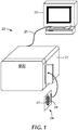
- FIG. 1 shows a perspective view of one embodiment of a system 20 for detecting and counting microbial colonies in a culture device.
- the system 20 comprises a scanner 21 coupled to an external computer 22 which performs imaging analysis of the images generated by the scanner.
- External computer 22 may include, for example, a microprocessor programmed for image analysis of a culture device 24.
- External computer 22 may comprise a personal computer (PC), desktop computer, laptop computer, handheld computer, workstation, tablet personal computing device, mobile device or the like.
- PC personal computer
- desktop computer laptop computer
- handheld computer handheld computer
- workstation tablet personal computing device
- mobile device mobile device or the like.
- software programs can be loaded on external computer 22 to facilitate image analysis of images of culture device 24 generated by scanner 21.
- Scanner 21 is coupled to external computer 22 via interface 25.
- Interface 25 may comprise a Universal Serial Bus (USB) interface, a Universal Serial Bus 2 (USB2) interface, an IEEE 1394 Fire Wire interface, a Small Computer System Interface (SCSI) interface, an Advance Technology Attachment (ATA) interface, a serial ATA interface, a Peripheral Component Interconnect (PCI) interface, a conventional serial or parallel interface, wireless connection or the like.
- USB Universal Serial Bus
- USB2 Universal Serial Bus 2
- IEEE 1394 Fire Wire interface Small Computer System Interface
- SCSI Small Computer System Interface
- ATA Advance Technology Attachment
- serial ATA serial ATA interface
- PCI Peripheral Component Interconnect
- the culture device 24 optionally may include indicia 29, such as a bar code or other type of identification marking used to identify culture device 24. RFID tags, two-dimensional optically detectable codes, or the like, may also be used as indicia.
- indicia 29 may identify the type of microorganism being grown and tested on the culture device 24.
- Scanner 21 can be designed to draw the culture device 24 into scanner 21 to a first location and generate an image of indicia 29, and then draw the culture device 24 to a second location and generate an image of the growth area 27. In this manner, images of indicia 29 and growth area 27 of the culture device can be generated by system 20. Alternatively, a single image may capture both indicia 29 and the growth area 27. In either case, the scanning of indicia 29 can facilitate identification of the type of plate being used so that one or more desirable counting rules can be applied in an automated fashion.
- the culture device 24 may comprise a thin film culture device sold by 3M under the trade name PETRIFILM plates.
- Culture device 24 can be utilized to facilitate the rapid growth and detection of microorganisms commonly associated with food contamination, including, for example, aerobic bacteria, E. coli, coliform, enterobacteria, yeast, mold, Staphylococcus aureus , Listeria, Campylobacter, or the like.
- Culture devices generally comprise one type of growth medium commonly used for biological growth and bacterial detection and enumeration. The invention, however, may also be applied with a wide variety of other types of growth media.
- the thin film culture device can have a front side that comprises a transparent film cover sheet and a back side comprises a translucent substrate, such as a PETRIFILM E . coli /Coliform Count Plate, a PETRIFILM Coliform Count Plate, and a PETRIFILM Enterobacteriaceae Count Plate, for example.
- a relatively thin (e.g., approximately 1-2 mm thick) culture medium disposed between a translucent film and a transparent film provides optical conditions that are beneficial for distinguishing colonies according to the present disclosure.
- various aspects of the method of the present disclosure establishes rules that can be applied during image processing.
- the rules described in greater detail below can form part of a colony counting algorithm executed in system 20.
- the rules may be used individually or in any combination with other image analysis rules (the counting rules described in International Patent Publication No. WO 2005/062744 ), depending on the type of growth medium being scanned and the problems that may be encountered.
- Application of one or more of the counting rules can improve a biological scanning system such as system 20 by improving the accuracy of automated counts of microbial colonies on a growth medium such as a thin film culture device or the like.
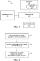
- FIG. 2 is a block diagram of a biological scanning system 30, which may correspond to system 20 ( FIG. 1 ).
- System 30 includes an imaging device 32 that generates one or more images of a growth medium and provides the images to processor 34.
- Processor 34 is coupled to memory 36.
- Memory 36 stores various processor-executable software instructions that facilitate image analysis of the images generated by imaging device 32.
- memory 36 stores one or more counting rules 37 which are applied during image analysis to improve the accuracy of automated counts of microbial colonies on a culture device.
- Output device 38 receives the results determined by processor 34 and provides the results to a user.
- imaging device 32 may comprise a 2-dimensional monochromatic camera for generating one or more images of a culture device.
- Various illuminators may be used to illuminate the front and back of culture device.
- the illuminators can illuminate the culture device with one or more colors, and one or more images of the culture device can be generated by imaging device 32.
- a controller (not shown) can control a ratio of front-side illumination to back side illumination for each image of the culture device.
- a non-limiting example of an imaging device that provides front-side and back-side illumination that can be used to image a thin film culture device, optionally with a plurality of illumination colors, is described in U.S. Patent No. 8,094,916 .
- a first image can be obtained using 100% of the illumination coming from illuminators illuminating the front side of the culture device and 0% of the illumination coming from illuminators illuminating the back side of the culture device and a second image can be obtained using 0% of the illumination coming from illuminators illuminating the front side of the culture device and 100% of the illumination coming from illuminators illuminating the back side of the culture device.
- a first image can be obtained using 80% of the illumination coming from illuminators illuminating the front side of the culture device and 20% of the illumination coming from illuminators illuminating the back side of the culture device and a second image can be obtained using 20% of the illumination coming from illuminators illuminating the front side of the culture device and 80% of the illumination coming from illuminators illuminating the back side of the culture device.
- the ratio of front-side illumination to back-side illumination can be selected to provide optimum contrast for a particular type of nutrient medium in the culture device.
- the first image is produced while illuminating the device with a first ratio (e.g., 100%:0%) of front-side illumination to back-side illumination and the second image is produced while illuminating the device with a second ratio (e.g., 0%:100%) of front-side illumination to back-side illumination that is lower than the first ratio.
- a first ratio e.g., 100%:0%
- a second ratio e.g., 0%:100% of front-side illumination to back-side illumination that is lower than the first ratio.
- the first ratio can be greater than 1:1.
- the second ratio can be less than 1:1.
- first image refers to an image that is obtained while the culture device receives illumination primarily from the front side of the plate
- second image refers to an image that that is obtained while the culture device receives illumination primarily from the back side of the plate.
- first image refers to an image that is obtained while the culture device receives illumination primarily from the front side of the plate
- second image refers to an image that that is obtained while the culture device receives illumination primarily from the back side of the plate.
- An implied temporal order of obtaining the images is not intended by the use of the terms "first image” and "second image”. Accordingly, a first image of a culture device can be obtained before or after a second image of the culture device. In addition, one of the images (e.g., the first image or second image, respectively) does not need to be obtained by the imaging culture device immediately after obtaining the other image (e.g., the second image or first image, respectively).
- the first and second images are obtained closely enough in time to obviate the possibility of significant biological changes (e.g., growth or enzyme activity) or physical changes (e.g., dehydration) occurring during the intervening time between image acquisitions.
- the first image is obtained within about 30 seconds of the time at which the second image is obtained.
- the imaging device in a system wherein the imaging device is positioned facing the front side of the culture device and the illuminators are also positioned such that the illumination is directed at the front side of the culture device, the image produced by the imaging device substantially comprises light that is reflected from the culture device and the contents thereof.
- the person having ordinary skill in the art will also recognize that, in a system wherein the imaging device is positioned facing the front side of the culture device and the illuminators are also positioned such that the illumination is directed at the back side of the culture device, the image produced by the imaging device substantially comprises light that is transmitted by and/or refracted by the culture device and the contents thereof.
- the images are provided to processor 34 and may also be stored in memory 36. In any case, the images are analyzed by applying counting rules 37 in order to determine bacteria counts on the culture device.
- the resolution of imaging device 32 may be approximately 155 pixels per centimeter. In that case, a one centimeter line in the image is 155 pixels long.
- Processor 34 may comprise a general-purpose microprocessor that executes software stored in memory 36.
- processor 34 may comprise an application specific integrated circuit (ASIC) or other specifically designed processor.
- ASIC application specific integrated circuit
- processor 34 executes various counting rules 37 to improve the accuracy of automated counts of microbial colonies on a culture device.
- Memory 36 is one example, of a computer readable medium that stores processor executable software instructions applied by processor 34.
- memory 36 may comprise random access memory (RAM), read-only memory (ROM), non-volatile random access memory (NVRAM), electrically erasable programmable read-only memory (EEPROM), flash memory, or the like.
- Counting rules 37 such as those described below, are stored in memory 36 and may form part of a larger software program used for image analysis.
- Output device 38 typically comprises a display screen used to communicate results to a user. However, output device 38 could also comprise other types of devices such as a printer or the like. Output device 38 may form part of a scanning unit, such as display (not shown), or may be external to the scanning unit, such as the display screen of external computer 22 ( FIG. 1 ).
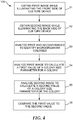
- FIG. 3 is a flow diagram illustrating a process of automated culture device analysis.
- processor 34 receives one or more images of a culture device (step 41).
- Processor 34 invokes various software routines from memory 36 to count the microbial colonies on the culture device (step 42). For example, bacterial colonies may be identified according to a characteristic color they produce after reacting (i.e., directly or indirectly) with one or more indicator compounds in the nutrient medium. Other aspects of colony recognition are discussed below.
- the software executed by processor 34 can allow for identification of the growth area on the culture device and automated counting of bacterial colonies based on color changes in the growth area where the colonies have grown during incubation.
- processor 34 applies one or more rules to improve the accuracy of the count of microbial colonies on the growth medium (step 43).
- the rules may be applied individually or various combinations of rules may be used, depending on the type of culture device being analyzed.
- the rules may be individually invoked from memory 36 or may form subroutines of a larger image analysis software program.
- the rules may be applied individually or various sets of the rules may be applied. If a set of rules are used, then the order in which the rules are applied may be selected based on the type of plate being scanned. The selected order for application of the rules may affect the end result.
- Various subsets of the rules may also be applied in any order, and the selected order for a subset of rules may also affect the end result.
- FIG. 4 shows one embodiment of a method 100 according to the present disclosure.
- the method comprises the step 51 of obtaining a first image while illuminating the front side of a culture device and the step 52 of obtaining a second image while illuminating the back side of the culture device.
- the front side and back side of the culture device can be illuminated with an imaging system as disclosed herein.
- the method 100 further comprises the step 53 of analyzing the first and second images to identify microorganism colonies in each image.
- the first and second images are obtained so as to define objects in the image in shades of at least one color.
- analyzing the first and second images to identify microorganism colonies in each image can comprise identifying objects in the image as colonies according to image analysis methods that are well known in the art.
- Weiss describes techniques to identify microbial colonies in an image based upon one or more criteria including object size, visibility, color, surface quality, and shape ( U.S. Patent No. 6,243,486 .
- a method to detect a microbial colony that reacts with an indicator compound comprising TTC can be configured to detect a shade of the color red and a method to detect a microbial colony that reacts with an indicator compound comprising 5-bromo-4-chloro-3-indolyl- ⁇ -D-glucuronide can be configured to detect a shade of the color blue.
- a thin film culture device having a second indicator that is a chromogenic enzyme substrate comprising an indolyl group is illuminated from the back-side and an image is taken with an illumination intensity and an integration time (i.e., exposure time) that results in near saturation of the image.
- an integration time i.e., exposure time
- the area in the image defined by the cell mass of a microbial colony can appear to be significantly darker (i.e., permits less transmittance of light) than the zone of colored product (i.e., from the chromogenic enzyme substrate) surrounding the colony. This facilitates the discrimination between the relatively smaller microbial colony from the relatively larger colored zone of colored product (i.e., from the enzyme reaction) surrounding the colony.
- an imaging processor can readily discriminate the edges of the colony mass from the edges of colored product surrounding the colony based on the differences in the color intensity of the regions (e.g., the difference in brightness between the image of the colony and the image of a colored zone surrounding the colony, if present).
- Analyzing the first and second images to identify microorganism colonies in each image further comprises identifying the location any colonies detected in the images.
- the locations will be used to identify and compare measurable parameters associated with coincident colonies in each image.
- the locations can be identified by X-Y coordinates in each image.
- both the first and second images are obtained without moving or otherwise handling the culture device after the first image is obtained but before the second image is obtained.
- registration landmarks e.g., two or more corners of a PETRIFILM plate or registration marks made on any culture device
- the first and second images are analyzed to calculate a value related to a size parameter for each coincidental colony.
- the size parameter can be, for example, a mean colony diameter, a minimum colony diameter, a maximum colony diameter, or a colony area.
- a first size parameter value is calculated for a particular colony in the first image ( FIG. 4 , step 54) and a second size parameter value is calculated for the corresponding coincident colony in the second image ( FIG. 4 , step 55).
- the method 100 further comprises the step (56) of comparing the first size parameter value to the second size parameter value. If the first size parameter value calculated from a first image of a given colony is within a predetermined range (e.g., 80% to 120%, 90% to 110%, or 95% to 105%) of the second size parameter value calculated from a second image of the given colony, the colony is counted as a colony belonging to a first group (e.g., group "A": probable non- E . coli microorganisms).
- group "A" probable non- E . coli microorganisms
- group "A" microorganisms react with a first indicator compound (e.g., TTC) that produces a nondiffusible product but does not react with a second indicator compound (e.g., 5-bromo-4-chloro-3-indolyl- ⁇ -D-glucuronide) that produces a diffusible product.
- a first indicator compound e.g., TTC
- a second indicator compound e.g., 5-bromo-4-chloro-3-indolyl- ⁇ -D-glucuronide
- the colony is counted as a colony belonging to a second group (e.g., group "B": probable E. coli microorganisms).
- group "B” probable E. coli microorganisms
- group "B" microorganisms react with a first indicator compound (e.g., TTC) that produces a nondiffusible product and reacts with a second indicator compound (e.g., 5-bromo-4-chloro-3-indolyl- ⁇ -D-glucuronide) to produce a diffusible product, which results in the first size parameter value being greater than the second size parameter value.
- a first indicator compound e.g., TTC
- a second indicator compound e.g., 5-bromo-4-chloro-3-indolyl- ⁇ -D-glucuronide
- FIG. 5 is a flow diagram illustrating the rule for differentiating colonies into a plurality of colony types according to the present disclosure.
- processor 34 invokes software stored in memory 36 to identify and map the location of colonies in the first image and second image (step 61). In particular, processor 34 determines whether a colony identified in the first image maps to the same location as a colony identified in the second image (step 62). If coincidental colonies are found in the first and second images, the processor 34 calculates a size parameter value for the coincidental colonies and compares the values to determine whether they are different (step 63).
- the colony in the culture device is counted as a first type ("Type A", as indicated in step 64). If the values are different (e.g., the value for the first image is less than the value for the second image), the colony in the culture device is counted as a second type ("Type B", as indicated in step 65).
- a Type "A" colony may react with TTC and not with 5-bromo-4-chloro-3-indolyl- ⁇ -D-glucuronide in a PETRIFILM E . coli /Coliform Count Plate and, thus, would be identified as a non-E. coli colony.
- a Type "B" colony may react with TTC and with 5-bromo-4-chloro-3-indolyl- ⁇ -D-glucuronide in a PETRIFILM E . coli /Coliform Count Plate and, thus, would be identified as an E. coli colony.
- Analyzing the images can include RGB (red/green/blue) image processing algorithms.
- analyzing the images can include HSI (hue, saturation, and intensity), HSL (hue, saturation, and lightness), HSV (hue, saturation, and value) algorithms, or combinations thereof.
- FIG. 6 shows a black and white image of a portion of a thin film culture device having two types of microbial colonies growing therein. The image was obtained while illuminating only the back side of the culture device, as described in Example 1. Within the growth area is a plurality of microbial colonies, including colonies of two different types "A" and "B", respectively. Colonies belonging to type “A” react with a first indicator compound that reacts with and stains the cell mass of the bacterial colony. Colonies belonging to type “B” interact with the first compound and, in addition, also react with a second indicator compound that imparts a color change to the microbial colony and/or the culture medium surrounding the colony.
- the diameters of representative colonies belonging to type A (first colony 74) and type B (second colony 75) were determined according to the technique described in Example 1.
- the data (listed in Table 1 below) show the diameter of first colony 74 in the back-illuminated image is 22 pixels and the diameter of second colony 75 in the back-illuminated image is 15 pixels.
- FIG. 6 shows that, with this type of illumination (i.e., back-side illumination), a size parameter (i.e., the colony diameter) of representative colonies belonging to both types (A and B) may have approximately the same magnitude.
- a path 91 of a line scan of a portion of the growth area that includes at least one microbial colony.
- FIG. 7 shows a black and white image of the same portion of the thin film culture device shown in FIG. 6 .
- the image was obtained while illuminating only the front side of the culture device, as described in Example 1.
- the diameters of a first colony 74 and second colony 75 were determined according to the technique described in Example 1.
- the data show the diameter of first colony 74 in the front-illuminated image is 22 pixels and the diameter of second colony 75 in the front-illuminated image is 45 pixels.
- a size parameter i.e., the colony diameter
- a and B may have different magnitudes (e.g., substantially different magnitudes).
- a path 92 of a line scan of a portion of the growth area that includes at least one microbial colony. Path 92 corresponds to the same pixels as those in path 91 of FIG. 6A .
- FIG. 8 shows a graph of the transmitted pixel intensities for red, green, and blue obtained from pixels along the path 91 in the back-lit image of FIG. 6A .
- FIG. 9 shows a graph of the reflected color intensities for red, green, and blue obtained from pixels along the path 92 in the front-lit image of FIG. 7A.
- FIG. 9 shows smaller differences in pixel intensities between the pixels comprising the colony centers and the pixels comprising the growth medium adjacent the colonies.
- the use of a scanning system with a counting rule for differentiating microbial colonies has been described.
- the counting rule can be used in a scanning system to improve the accuracy of automated counts of microbial colonies on a culture device.
- a computer readable medium stores processor executable instructions that embody one or more of the rules described above.
- the computer readable medium may comprise non-transitory computer readable media such as random access memory (RAM), read-only memory (ROM), non-volatile random access memory (NVRAM), electrically erasable programmable read-only memory (EEPROM), flash memory, or the like.
- the computer readable medium may also comprise a non-volatile memory such as a CD-ROM used to deliver the software to customers.
- the computer readable medium may comprise an electromagnetic carrier wave, e.g., for delivering the software over a network such as the internet.
- Example hardware implementations include implementations within an application specific integrated circuit (ASIC), a field programmable gate array (FPGA), specifically designed hardware components, or any combination thereof.
- ASIC application specific integrated circuit
- FPGA field programmable gate array
- one or more of the techniques described herein may be partially executed in hardware, software or firmware.
- Tryptic Soy Broth (TSB, Catalog # K89) was obtained from Hardy Diagnostics (Santa Maria, CA). Microbial strains E. coli (ATCC 25922), E. coli (3M-FR4), Salmonella enterica (ATCC 51812) and Enterobacter amnigenus (ATCC 51898) were obtained from Microbiologics Inc (St Cloud, MN). An overnight TSB culture was prepared for each microbial strain. Thin film culture devices (3M PETRIFILM E . Coli /Coliform Count (EC) Plates) and Butterfield's Phosphate Buffer were both obtained from the 3M Company (St. Paul, MN).
- the colonies on the PETRIFILM culture plate were imaged and identified using a culture device imaging system.
- the imaging system contained a centrally positioned glass platen (White Flashed Opal Glass) that served as a platform for placement of the culture plate.
- the culture plate was illuminated on the front side using two separate sets of light emitting diodes (each set containing two red LEDs, two green LEDs, and two blue LEDs) One set was positioned above to the left (relative to the longitudinal dimension) of the culture plate and the other set was positioned above and to the right (relative to the longitudinal dimension of the culture plate).
- Light from the LEDs positioned above the culture device was directed away from the culture device and into a light-diffusing reflective surface, which directed a substantially uniform illumination pattern onto the front side of the culture plate.
- the culture plate was illuminated on the back side using two separate sets of light emitting diodes (each set containing two red LEDs, two green LEDs, and two blue LEDs). One set was positioned below and to the left (relative to the longitudinal dimension) of the culture plate and the other set was positioned below and to the right (relative to the longitudinal dimension of the culture plate).
- Light from the LEDs positioned below the culture device was directed away from the culture device and into a light-diffusing reflective surface, which directed a substantially uniform illumination pattern onto the back side of the glass platen (described above), and created a uniform illumination pattern on the back side of the culture plate.
- An Aptina Model MT9P031 CMOS imaging sensor (Aptina Imaging, San Jose, CA) was orthogonally-positioned above the platform in order to take images of the culture plate.
- the imaging sensor and platform were adjusted so that the culture plate was positioned within the focal plane of the sensor.
- the culture plate was oriented on the platform so that front side (transparent film side) of the culture plate faced the imaging sensor.
- a black cover was used to isolate the imaging device from room light.
- the image exposures were selected so that, in the acquired images, less than about 10% of the pixels in a histogram of all of the image pixels were saturated.
- a first image was taken using only illumination from the front side of the culture plate and a second image was taken using only illumination from the back side of the culture plate.
- Both images were taken with the culture plate being maintained in exactly the same position on the platform (i.e., the plates were not moved from the platform until both images were acquired). This allowed for the identification of coincidental colonies in the two images by matching the corresponding X-Y coordinate positions.
- the two images were analyzed for colony type using ImagePro Plus software (Media Cybernetics, Rockville, MD). For each image, the size of an individual colony was determined by measuring the colony diameter.
- the imaging program analyzed for changes in red, green, and blue pixel intensities observed along a line of pixels incorporating the longest dimension of the suspect colony's image. The pixel positions that defined a change in intensity relative to the local background were used to mark the margins of the colony image and to measure the colony diameter (diameter distance was reported as the number of pixels located between the pixel points marking the colony margins). The diameter measurements for coincidental colonies in the two images were then compared to determine the colony type. The results for three representative colonies on the culture plate are presented in Table 1.
- Table 1 Colony Designation Colony Diameter (Front-side Illumination) (pixels) Colony Diameter (Back-side Illumination) (pixels) Colony Diameter Measured Difference (pixels) Colony Type** 1 22 22 0 non- E . coli 2 45 15 30 E. coli 3 100* 22 78 E. coli 4 100* 23 77 E. coli *Colony 3 and Colony 4 were both surrounded by a single, diffuse blue halo (i.e., a diffusion zone diffusion of the product of the chromogenic indicator surrounding the colony).
- a single, diffuse blue halo i.e., a diffusion zone diffusion of the product of the chromogenic indicator surrounding the colony.
- colonies 3 and 4 appeared as a single large colony using front-side illuminated image.
- the back-side illuminated image revealed that there were actually two separate colonies whose blue zones had merged together in the plate **Colony types were determined based upon the difference between the observed colony diameters measured using front-side-illuminated images compared to the colony diameters measured using back-side-illuminated images.
- Tryptic Soy Broth (TSB, Catalog # K89) was obtained from Hardy Diagnostics (Santa Maria, CA). Microbial strains E. coli (ATCC 25922), E. coli (3M-FR4), Salmonella enterica (ATCC 51812) and Enterobacter amnigenus (ATCC 51898) were obtained from Microbiologics Inc (St Cloud, MN). An overnight TSB culture was prepared for each microbial strain. Thin film culture devices (3M PETRIFILM E. Coli /Coliform Count (EC) Plates) and Butterfield's Phosphate Buffer were both obtained from the 3M Company (St. Paul, MN).
- the colonies on the PETRIFILM culture plate were imaged and identified using a culture device imaging system.
- the imaging system contained a centrally positioned glass platen (White Flashed Opal Glass) that served as a platform for placement of the culture plate.
- the culture plate was illuminated on the front side using two separate sets of light emitting diodes (each set containing two red LEDs, two green LEDs, and two blue LEDs) One set was positioned above to the left (relative to the longitudinal dimension) of the culture plate and the other set was positioned above and to the right (relative to the longitudinal dimension of the culture plate).
- Light from the LEDs positioned above the culture device was directed away from the culture device and into a light-diffusing reflective surface, which directed a substantially uniform illumination pattern onto the front side of the culture plate.
- the culture plate was illuminated on the back side using two separate sets of light emitting diodes (each set containing two red LEDs, two green LEDs, and two blue LEDs). One set was positioned below and to the left (relative to the longitudinal dimension) of the culture plate and the other set was positioned below and to the right (relative to the longitudinal dimension of the culture plate).
- Light from the LEDs positioned below the culture device was directed away from the culture device and into a light-diffusing reflective surface, which directed a substantially uniform illumination pattern onto the back side of the glass platen (described above), and created a uniform illumination pattern on the back side of the culture plate.
- An Aptina Model MT9P031 CMOS imaging sensor (Aptina Imaging, San Jose, CA) was orthogonally-positioned above the platform in order to take images of the culture plate.
- the imaging sensor and platform were adjusted so that the culture plate was positioned within the focal plane of the sensor.
- the culture plate was oriented on the platform so that front side (transparent film side) of the culture plate faced the imaging sensor.
- a black cover was used to isolate the imaging device from room light.
- the image exposures were selected so that, in the acquired images, less than about 10% of the pixels in a histogram of all of the image pixels were saturated.
- a first image was taken using only illumination from the front side of the culture plate and a second image was taken using only illumination from the back side of the culture plate.
- Both images were taken with the culture plate being maintained in exactly the same position on the platform (i.e., the plates were not moved from the platform until both images were acquired). This allowed for the identification of coincidental colonies in the two images by matching the corresponding X-Y coordinate positions.
- the two images were analyzed for colony type using ImagePro Plus software (Media Cybernetics, Rockville, MD). For each image, the size of an individual colony was determined by measuring the colony diameter.
- the imaging program analyzed for changes in red, green, and blue pixel intensities observed along a line of pixels incorporating the longest dimension of the suspect colony's image. The pixel positions that defined a change in intensity relative to the local background were used to mark the margins of the colony image and to measure the colony diameter (diameter distance was reported as the number of pixels located between the pixel points marking the colony margins). The diameter measurements for coincidental colonies in the two images were then compared to determine the colony type. The results for three representative colonies on the culture plate are presented in Table 1.
- Table 1 Colony Designation Colony Diameter (Front-side Illumination) (pixels) Colony Diameter (Back-side Illumination) (pixels) Colony Diameter Measured Difference (pixels) Colony Type** 1 22 22 0 non- E . coli 2 45 15 30 E. coli 3 100* 22 78 E. coli 4 100* 23 77 E. coli *Colony 3 and Colony 4 were both surrounded by a single, diffuse blue halo (i.e., a diffusion zone diffusion of the product of the chromogenic indicator surrounding the colony).
- a single, diffuse blue halo i.e., a diffusion zone diffusion of the product of the chromogenic indicator surrounding the colony.
- colonies 3 and 4 appeared as a single large colony using front-side illuminated image.
- the back-side illuminated image revealed that there were actually two separate colonies whose blue zones had merged together in the plate **Colony types were determined based upon the difference between the observed colony diameters measured using front-side-illuminated images compared to the colony diameters measured using back-side-illuminated images.
Description
- This application claims priority to
U.S. Provisional Patent Application No. 61/739,786, filed December 20, 2012 - Biological safety is a paramount concern in modern society. Testing for biological contamination in foods or other materials has become an important and often mandatory requirement for developers and distributors of food products. Biological testing is also used to identify bacteria or other agents in laboratory samples such as blood samples taken from medical patients, laboratory samples developed for experimental purposes, and other types of biological samples. Various techniques and devices can be utilized to improve biological testing and to streamline and standardize the biological testing process.
- A wide variety of culture devices have been developed. As one example, culture devices have been developed by 3M Company (hereafter "3M") of St. Paul, Minnesota. In particular, culture devices are sold by 3M under the trade name PETRIFILM plates. Culture devices can be utilized to facilitate the rapid growth and detection of microorganisms commonly associated with food contamination, including, for example, aerobic bacteria, E. coli, coliform, enterobacteria, yeast, mold, Staphylococcus aureus, Listeria, Campylobacter, and the like. The use of PETRIFILM plates, or other growth media, can simplify bacterial testing of food samples.
- Culture devices can be used to enumerate or identify the presence of bacteria so that corrective measures can be performed (in the case of food testing) or proper diagnosis can be made (in the case of medical use). In other applications, culture devices may be used to rapidly grow microorganisms in laboratory samples, e.g., for experimental purposes.
- Biological scanning units refer to devices used to scan and/or count microbial colonies. For example, a food sample or laboratory sample can be placed on a culture device, and then the plate can be inserted into an incubation chamber. After incubation, the culture device can be placed into the biological scanning unit for automated detection and enumeration of bacterial growth. In this manner, biological scanning units automate the detection and enumeration of microbial colonies in a culture device, and thereby improve the biological testing process by reducing human error.
- In general, the present disclosure is directed to a technique for distinguishing objects in a scanned image. In particular, the technique is used to differentiate two microorganism colony types that are present in a culture medium that includes two indicator compounds with which each type of microorganism may react. In addition, the technique further may be used to count the number of colonies of each microorganism type in the scanned image of the culture device. To count the colonies, a culture device containing the culture medium is inserted into a scanning unit. Upon insertion of the culture device, the scanning unit generates an image of the culture device. Then, the number of microorganism colonies can be counted or otherwise determined using image processing and analysis routines performed either within the scanning unit or by an external computing device, such as a desktop computer, workstation or the like. In accordance with the invention, a method of distinguishing colony types is described. The method can be used to improve the accuracy over existing methods of automated counts of microorganism colonies in a scanned image.
- Various aspects of the invention may provide a number of advantages. For example, the methods of the present disclosure may improve the accuracy of automated counts of microbial colonies on a culture device. In particular, the rules described herein may address problems that commonly occur, and which can otherwise undermine the accuracy of automated counting of agents on a growth plate.
- Additional details of these and other embodiments are set forth in the accompanying drawings and the description below. Other features, objects and advantages will become apparent from the description and drawings, and from the claims.
-
-
FIG. 1 is a perspective view of an exemplary system comprising a scanning device coupled to an external computer which performs imaging analysis of the images generated by the scanning device. -
FIG. 2 is a block diagram of a biological scanning system that may correspond to the system illustrated inFIG. 1 . -
FIG. 3 is a flow diagram illustrating a process of automated analysis of a microbial culture device. -
FIG. 4 is a block diagram of one embodiment of a method of analyzing a microbial culture device according to the present disclosure. -
FIG. 5 is a flow diagram of a counting rule to distinguish microbial colony types according to the present disclosure. -
FIG. 6 is a black and white image of a portion of a thin film culture device having two types of microbial colonies growing therein, wherein the image was obtained while illuminating only the back side of the culture device. -
FIG. 6A is a detailed view of a portion of the image ofFIG. 6 . -
FIG. 7 is a black and white image of the portion of the thin film culture device ofFIG. 6 , wherein the image was obtained while illuminating only the front side of the culture device. -
FIG. 7A is a detailed view of a portion of the image ofFIG. 7 . -
FIG. 8 is a graph of the relative intensities of red, green, and blue components, respectively, of the pixels in the line scan ofFIG. 6A . -
FIG. 9 is a graph of the relative intensities of red, green, and blue components, respectively, of the pixels in the line scan ofFIG. 7A . - Detection and counting of microorganisms is a universal problem in many diverse fields. Microorganisms occur in almost all foods, in water, in air, and on numerous surfaces and substances with which humans come in contact. Such microorganisms are often harmful and therefore must be measured and controlled.
- A widely used practice for detecting the presence of microorganisms in a substance (e.g., food, water, environmental residue) is to place a sample of the substance to be tested, suitably prepared, in a culture device, and to allow the microorganisms to grow into colonies. When cultured in such a medium, colonies become visible to the eye and can be counted. Each visible colony corresponds to one original microorganism. A method of the present disclosure is performed using such culture devices for growing and counting microbial colonies. Typically, the culture device includes an aqueous nutrient medium and a matrix (e.g., a gelling agent such as agar, guar gum, or pectin, for example) to maintain separation of individual colonies. Many culture devices further include indicator compounds as discussed herein. Culture devices for growing and counting microbial colonies include, for example, agar Petri dishes and thin film culture devices sold by 3M Company under the PETRIFILM trade name. PETRIFILM thin film culture devices are disclosed in numerous publications including, for example,
U.S. Patent Nos. 5,364,766 ;5,601,998 ; and5,681,712 . - Many culture media, including typical agar culture media and culture media used in PETRIFILM plates, include indicator compounds to indicate the presence of a microorganism. Indicator compounds include, for example, pH indicators, chromogenic enzyme substrates, and redox indicators. The indicator compounds, when converted directly or indirectly to a product, typically impart a color change to the microbial colony and/or the culture medium surrounding the colony. The color change often makes it easier to detect the presence of the microbial colony in the culture medium (e.g., it improves the color contrast between the colony and the culture medium) and may the color change also may serve to differentiate a particular colony that reacts with a particular indicator compound from another microbial colony that does not react with that indicator compound.
- Many types of culture media for growing and differentiating microorganisms include two or more indicator compounds. For example, the culture medium in a PETRIFILM E. coli Count Plate, when hydrated with an aqueous buffer and/or sample, contains a redox indicator (triphenyltetrazolium chloride, hereinafter "TTC") and a chromogenic enzyme substrate (5-bromo-4-chloro-3-indolyl-β-D-glucuronide, hereinafter "X-gluc"). The TTC reacts with microbial cells to form a reddish-colored formazan that stains the cell mass of any bacterial colony that grows in the Gram-negative selective growth medium. In contrast, the X-gluc reacts only with bacteria that, in addition to being able to grow in the selective growth medium, possess β-D-glucuronidase enzyme activity (e.g., E. coli strains that possess β-D-glucuronidase enzyme activity). Hydrolysis of X-gluc causes the formation of an indigo dye, which stains the cell mass of the colony blue and forms a blue halo (i.e. zone of diffusion of the indicator) surrounding the colony having β-D-glucuronidase enzyme activity.
- It is contemplated that the method of the present disclosure can be used to distinguish microbial colonies on the basis of their reaction with one or more of a plurality of indicator compounds even if the microbial cells react with the indicator compounds to form products that are substantially the same color. This is possible when the product of one of the indicator compounds remains associated with the cell mass of the microbial colony and the product of another indicator compound diffuses into the culture medium surrounding the cell mass of the colony.
- In the method of the present disclosure, the sample is prepared, inoculated into the culture device, and incubated according to procedures that are well known in the art. Sample preparation may optionally include dilution, enzymatic digestion, filtration, and/or sedimentation to reduce or remove nonmicrobial debris from the sample prior to introducing the sample into (e.g., pour-plating) or onto (e.g., surface-plating) the nutrient medium in the culture device.
- After a sufficient incubation period at a temperature suitable for the growth of the microorganisms suspected of being present in the sample, microbial colonies can be detected and counted using an imaging system to capture an image of microbial colonies in a culture device and applying various image-analysis schemes. Examples of imaging systems used to count and/or differentiate microbial colonies in a culture device can be found in International Publication No.
WO 98/59314 U.S. Patent Nos. 7,298,885 ;8,094,916 ; and7,496,225 . Examples of image analysis schemes to detect and/or enumerate microbial colonies in a culture device can be found inU.S. Patent Nos. 6,058,209 and6,243,486 . - The present disclosure is directed to techniques for counting microbial colonies in a culture device. The techniques can be used to improve the accuracy of automated counts of microbial colonies in a culture device. The counting rules disclosed herein are typically stored as computer-executable software instructions, and are executed by a processor in a biological scanning system. Alternatively, the rules may be implemented in hardware such as an application specific integrated circuit (ASIC), a field programmable gate array (FPGA), or various hardware components known in the art. The various rules described herein may be applied individually, or in any combination with other counting rules depending on the growth medium being scanned. In any case, by applying the rules described herein, the accuracy of automated counts of microbial colonies on a culture device can be improved.
- In any embodiment, a method of the present disclosure employs a system for detecting and counting microbial colonies in a culture device. Systems for detecting and counting microbial colonies in a culture device are described, for example, in International Patent Publication Nos.
WO 96/18720 WO 96/18167 WO 2005/062744 . -
FIG. 1 shows a perspective view of one embodiment of asystem 20 for detecting and counting microbial colonies in a culture device. Thesystem 20 comprises ascanner 21 coupled to anexternal computer 22 which performs imaging analysis of the images generated by the scanner.External computer 22 may include, for example, a microprocessor programmed for image analysis of aculture device 24.External computer 22 may comprise a personal computer (PC), desktop computer, laptop computer, handheld computer, workstation, tablet personal computing device, mobile device or the like. For example, software programs can be loaded onexternal computer 22 to facilitate image analysis of images ofculture device 24 generated byscanner 21. -
Scanner 21 is coupled toexternal computer 22 viainterface 25.Interface 25, for example, may comprise a Universal Serial Bus (USB) interface, a Universal Serial Bus 2 (USB2) interface, an IEEE 1394 Fire Wire interface, a Small Computer System Interface (SCSI) interface, an Advance Technology Attachment (ATA) interface, a serial ATA interface, a Peripheral Component Interconnect (PCI) interface, a conventional serial or parallel interface, wireless connection or the like. - The
culture device 24 optionally may includeindicia 29, such as a bar code or other type of identification marking used to identifyculture device 24. RFID tags, two-dimensional optically detectable codes, or the like, may also be used as indicia. In any case, indicia 29 may identify the type of microorganism being grown and tested on theculture device 24.Scanner 21 can be designed to draw theculture device 24 intoscanner 21 to a first location and generate an image ofindicia 29, and then draw theculture device 24 to a second location and generate an image of thegrowth area 27. In this manner, images ofindicia 29 andgrowth area 27 of the culture device can be generated bysystem 20. Alternatively, a single image may capture bothindicia 29 and thegrowth area 27. In either case, the scanning ofindicia 29 can facilitate identification of the type of plate being used so that one or more desirable counting rules can be applied in an automated fashion. - By way of example, the
culture device 24 may comprise a thin film culture device sold by 3M under the trade name PETRIFILM plates.Culture device 24 can be utilized to facilitate the rapid growth and detection of microorganisms commonly associated with food contamination, including, for example, aerobic bacteria, E. coli, coliform, enterobacteria, yeast, mold, Staphylococcus aureus, Listeria, Campylobacter, or the like. Culture devices generally comprise one type of growth medium commonly used for biological growth and bacterial detection and enumeration. The invention, however, may also be applied with a wide variety of other types of growth media. - In any embodiment, the thin film culture device can have a front side that comprises a transparent film cover sheet and a back side comprises a translucent substrate, such as a PETRIFILM E. coli/Coliform Count Plate, a PETRIFILM Coliform Count Plate, and a PETRIFILM Enterobacteriaceae Count Plate, for example. Without being bound by theory, it is believed the combination of a relatively thin (e.g., approximately 1-2 mm thick) culture medium disposed between a translucent film and a transparent film provides optical conditions that are beneficial for distinguishing colonies according to the present disclosure.
- In order to improve the accuracy of automated counts of microbial colonies on a culture device, various aspects of the method of the present disclosure establishes rules that can be applied during image processing. In other words, the rules described in greater detail below can form part of a colony counting algorithm executed in
system 20. The rules may be used individually or in any combination with other image analysis rules (the counting rules described in International Patent Publication No.WO 2005/062744 ), depending on the type of growth medium being scanned and the problems that may be encountered. Application of one or more of the counting rules can improve a biological scanning system such assystem 20 by improving the accuracy of automated counts of microbial colonies on a growth medium such as a thin film culture device or the like. -
FIG. 2 is a block diagram of abiological scanning system 30, which may correspond to system 20 (FIG. 1 ).System 30 includes animaging device 32 that generates one or more images of a growth medium and provides the images toprocessor 34.Processor 34 is coupled tomemory 36.Memory 36 stores various processor-executable software instructions that facilitate image analysis of the images generated by imagingdevice 32. In particular,memory 36 stores one or more counting rules 37 which are applied during image analysis to improve the accuracy of automated counts of microbial colonies on a culture device.Output device 38 receives the results determined byprocessor 34 and provides the results to a user. - By way of example,
imaging device 32 may comprise a 2-dimensional monochromatic camera for generating one or more images of a culture device. Various illuminators (not shown) may be used to illuminate the front and back of culture device. For example, the illuminators can illuminate the culture device with one or more colors, and one or more images of the culture device can be generated by imagingdevice 32. In addition, a controller (not shown) can control a ratio of front-side illumination to back side illumination for each image of the culture device. A non-limiting example of an imaging device that provides front-side and back-side illumination that can be used to image a thin film culture device, optionally with a plurality of illumination colors, is described inU.S. Patent No. 8,094,916 . - In an embodiment, a first image can be obtained using 100% of the illumination coming from illuminators illuminating the front side of the culture device and 0% of the illumination coming from illuminators illuminating the back side of the culture device and a second image can be obtained using 0% of the illumination coming from illuminators illuminating the front side of the culture device and 100% of the illumination coming from illuminators illuminating the back side of the culture device. In another embodiment, for example, a first image can be obtained using 80% of the illumination coming from illuminators illuminating the front side of the culture device and 20% of the illumination coming from illuminators illuminating the back side of the culture device and a second image can be obtained using 20% of the illumination coming from illuminators illuminating the front side of the culture device and 80% of the illumination coming from illuminators illuminating the back side of the culture device. The ratio of front-side illumination to back-side illumination can be selected to provide optimum contrast for a particular type of nutrient medium in the culture device.
- In any embodiment of the method, the first image is produced while illuminating the device with a first ratio (e.g., 100%:0%) of front-side illumination to back-side illumination and the second image is produced while illuminating the device with a second ratio (e.g., 0%:100%) of front-side illumination to back-side illumination that is lower than the first ratio. In any embodiment, the first ratio can be greater than 1:1. In any embodiment, the second ratio can be less than 1:1.
- It should be noted that "first image", as used herein, refers to an image that is obtained while the culture device receives illumination primarily from the front side of the plate and "second image", as used herein refers to an image that that is obtained while the culture device receives illumination primarily from the back side of the plate. An implied temporal order of obtaining the images is not intended by the use of the terms "first image" and "second image". Accordingly, a first image of a culture device can be obtained before or after a second image of the culture device. In addition, one of the images (e.g., the first image or second image, respectively) does not need to be obtained by the imaging culture device immediately after obtaining the other image (e.g., the second image or first image, respectively). It is recommended the first and second images are obtained closely enough in time to obviate the possibility of significant biological changes (e.g., growth or enzyme activity) or physical changes (e.g., dehydration) occurring during the intervening time between image acquisitions. Thus, in a preferred embodiment, the first image is obtained within about 30 seconds of the time at which the second image is obtained.
- A person having ordinary skill in the art will recognize that, in a system wherein the imaging device is positioned facing the front side of the culture device and the illuminators are also positioned such that the illumination is directed at the front side of the culture device, the image produced by the imaging device substantially comprises light that is reflected from the culture device and the contents thereof. In addition, the person having ordinary skill in the art will also recognize that, in a system wherein the imaging device is positioned facing the front side of the culture device and the illuminators are also positioned such that the illumination is directed at the back side of the culture device, the image produced by the imaging device substantially comprises light that is transmitted by and/or refracted by the culture device and the contents thereof.
- The images are provided to
processor 34 and may also be stored inmemory 36. In any case, the images are analyzed by applyingcounting rules 37 in order to determine bacteria counts on the culture device. The resolution ofimaging device 32 may be approximately 155 pixels per centimeter. In that case, a one centimeter line in the image is 155 pixels long. -
Processor 34 may comprise a general-purpose microprocessor that executes software stored inmemory 36. Alternatively,processor 34 may comprise an application specific integrated circuit (ASIC) or other specifically designed processor. In any case,processor 34 executesvarious counting rules 37 to improve the accuracy of automated counts of microbial colonies on a culture device. -
Memory 36 is one example, of a computer readable medium that stores processor executable software instructions applied byprocessor 34. By way of example,memory 36 may comprise random access memory (RAM), read-only memory (ROM), non-volatile random access memory (NVRAM), electrically erasable programmable read-only memory (EEPROM), flash memory, or the like. Countingrules 37 such as those described below, are stored inmemory 36 and may form part of a larger software program used for image analysis. -
Output device 38 typically comprises a display screen used to communicate results to a user. However,output device 38 could also comprise other types of devices such as a printer or the like.Output device 38 may form part of a scanning unit, such as display (not shown), or may be external to the scanning unit, such as the display screen of external computer 22 (FIG. 1 ). -
FIG. 3 is a flow diagram illustrating a process of automated culture device analysis. As shown inFIG. 3 ,processor 34 receives one or more images of a culture device (step 41).Processor 34 invokes various software routines frommemory 36 to count the microbial colonies on the culture device (step 42). For example, bacterial colonies may be identified according to a characteristic color they produce after reacting (i.e., directly or indirectly) with one or more indicator compounds in the nutrient medium. Other aspects of colony recognition are discussed below. The software executed byprocessor 34 can allow for identification of the growth area on the culture device and automated counting of bacterial colonies based on color changes in the growth area where the colonies have grown during incubation. - In accordance with the invention,
processor 34 applies one or more rules to improve the accuracy of the count of microbial colonies on the growth medium (step 43). The rules may be applied individually or various combinations of rules may be used, depending on the type of culture device being analyzed. The rules may be individually invoked frommemory 36 or may form subroutines of a larger image analysis software program. The rules may be applied individually or various sets of the rules may be applied. If a set of rules are used, then the order in which the rules are applied may be selected based on the type of plate being scanned. The selected order for application of the rules may affect the end result. Various subsets of the rules may also be applied in any order, and the selected order for a subset of rules may also affect the end result. -
FIG. 4 shows one embodiment of amethod 100 according to the present disclosure. The method comprises thestep 51 of obtaining a first image while illuminating the front side of a culture device and thestep 52 of obtaining a second image while illuminating the back side of the culture device. The front side and back side of the culture device can be illuminated with an imaging system as disclosed herein. Themethod 100 further comprises thestep 53 of analyzing the first and second images to identify microorganism colonies in each image. - The first and second images are obtained so as to define objects in the image in shades of at least one color. Thus, analyzing the first and second images to identify microorganism colonies in each image can comprise identifying objects in the image as colonies according to image analysis methods that are well known in the art. For example, Weiss describes techniques to identify microbial colonies in an image based upon one or more criteria including object size, visibility, color, surface quality, and shape (
U.S. Patent No. 6,243,486 . As discussed above, a method to detect a microbial colony that reacts with an indicator compound comprising TTC can be configured to detect a shade of the color red and a method to detect a microbial colony that reacts with an indicator compound comprising 5-bromo-4-chloro-3-indolyl-β-D-glucuronide can be configured to detect a shade of the color blue. - In a preferred embodiment of the method, a thin film culture device having a second indicator that is a chromogenic enzyme substrate comprising an indolyl group is illuminated from the back-side and an image is taken with an illumination intensity and an integration time (i.e., exposure time) that results in near saturation of the image. Under the conditions of this preferred embodiment, the area in the image defined by the cell mass of a microbial colony can appear to be significantly darker (i.e., permits less transmittance of light) than the zone of colored product (i.e., from the chromogenic enzyme substrate) surrounding the colony. This facilitates the discrimination between the relatively smaller microbial colony from the relatively larger colored zone of colored product (i.e., from the enzyme reaction) surrounding the colony. For example, under these conditions an imaging processor can readily discriminate the edges of the colony mass from the edges of colored product surrounding the colony based on the differences in the color intensity of the regions (e.g., the difference in brightness between the image of the colony and the image of a colored zone surrounding the colony, if present).
- Analyzing the first and second images to identify microorganism colonies in each image further comprises identifying the location any colonies detected in the images. The locations will be used to identify and compare measurable parameters associated with coincident colonies in each image. The locations can be identified by X-Y coordinates in each image. Thus, in a preferred embodiment, both the first and second images are obtained without moving or otherwise handling the culture device after the first image is obtained but before the second image is obtained. Alternatively, registration landmarks (e.g., two or more corners of a PETRIFILM plate or registration marks made on any culture device) can be used to orient the images properly in order to determine coincidental colonies in the first and second images.
- After analyzing the first image and second image to identify coincidental colonies, the first and second images are analyzed to calculate a value related to a size parameter for each coincidental colony. The size parameter can be, for example, a mean colony diameter, a minimum colony diameter, a maximum colony diameter, or a colony area. Thus a first size parameter value is calculated for a particular colony in the first image (
FIG. 4 , step 54) and a second size parameter value is calculated for the corresponding coincident colony in the second image (FIG. 4 , step 55). - The
method 100 further comprises the step (56) of comparing the first size parameter value to the second size parameter value. If the first size parameter value calculated from a first image of a given colony is within a predetermined range (e.g., 80% to 120%, 90% to 110%, or 95% to 105%) of the second size parameter value calculated from a second image of the given colony, the colony is counted as a colony belonging to a first group (e.g., group "A": probable non-E. coli microorganisms). In this case, group "A" microorganisms react with a first indicator compound (e.g., TTC) that produces a nondiffusible product but does not react with a second indicator compound (e.g., 5-bromo-4-chloro-3-indolyl-β-D-glucuronide) that produces a diffusible product. - Conversely, if the first size parameter value calculated from a first image of a given colony is greater than the second size parameter value (e.g., at least 20% greater than, at least 50% greater than, or at least 100% greater than the second size parameter value) calculated from the second image of the given colony, the colony is counted as a colony belonging to a second group (e.g., group "B": probable E. coli microorganisms). In this case, group "B" microorganisms react with a first indicator compound (e.g., TTC) that produces a nondiffusible product and reacts with a second indicator compound (e.g., 5-bromo-4-chloro-3-indolyl-β-D-glucuronide) to produce a diffusible product, which results in the first size parameter value being greater than the second size parameter value.
-
FIG. 5 is a flow diagram illustrating the rule for differentiating colonies into a plurality of colony types according to the present disclosure. As illustrated inFIG. 2 ,processor 34 invokes software stored inmemory 36 to identify and map the location of colonies in the first image and second image (step 61). In particular,processor 34 determines whether a colony identified in the first image maps to the same location as a colony identified in the second image (step 62). If coincidental colonies are found in the first and second images, theprocessor 34 calculates a size parameter value for the coincidental colonies and compares the values to determine whether they are different (step 63). If the values are not different (e.g., within a predetermined range, as discussed above), the colony in the culture device is counted as a first type ("Type A", as indicated in step 64). If the values are different (e.g., the value for the first image is less than the value for the second image), the colony in the culture device is counted as a second type ("Type B", as indicated in step 65). By way of example, a Type "A" colony may react with TTC and not with 5-bromo-4-chloro-3-indolyl-β-D-glucuronide in a PETRIFILM E. coli/Coliform Count Plate and, thus, would be identified as a non-E. coli colony. Conversely, a Type "B" colony may react with TTC and with 5-bromo-4-chloro-3-indolyl-β-D-glucuronide in a PETRIFILM E. coli/Coliform Count Plate and, thus, would be identified as an E. coli colony. - Analyzing the images can include RGB (red/green/blue) image processing algorithms. Alternatively, or additionally, analyzing the images can include HSI (hue, saturation, and intensity), HSL (hue, saturation, and lightness), HSV (hue, saturation, and value) algorithms, or combinations thereof.
-
FIG. 6 shows a black and white image of a portion of a thin film culture device having two types of microbial colonies growing therein. The image was obtained while illuminating only the back side of the culture device, as described in Example 1. Within the growth area is a plurality of microbial colonies, including colonies of two different types "A" and "B", respectively. Colonies belonging to type "A" react with a first indicator compound that reacts with and stains the cell mass of the bacterial colony. Colonies belonging to type "B" interact with the first compound and, in addition, also react with a second indicator compound that imparts a color change to the microbial colony and/or the culture medium surrounding the colony. The diameters of representative colonies belonging to type A (first colony 74) and type B (second colony 75) were determined according to the technique described in Example 1. The data (listed in Table 1 below) show the diameter offirst colony 74 in the back-illuminated image is 22 pixels and the diameter ofsecond colony 75 in the back-illuminated image is 15 pixels. Thus,FIG. 6 shows that, with this type of illumination (i.e., back-side illumination), a size parameter (i.e., the colony diameter) of representative colonies belonging to both types (A and B) may have approximately the same magnitude. Also shown inFIG. 6A is apath 91 of a line scan of a portion of the growth area that includes at least one microbial colony. -
FIG. 7 shows a black and white image of the same portion of the thin film culture device shown inFIG. 6 . The image was obtained while illuminating only the front side of the culture device, as described in Example 1. The diameters of afirst colony 74 andsecond colony 75 were determined according to the technique described in Example 1. The data show the diameter offirst colony 74 in the front-illuminated image is 22 pixels and the diameter ofsecond colony 75 in the front-illuminated image is 45 pixels. Thus,FIG. 7 shows that, with this type of illumination (i.e., front-side illumination), a size parameter (i.e., the colony diameter) of representative colonies belonging to both types (A and B) may have different magnitudes (e.g., substantially different magnitudes). Also shown inFIG. 7A is apath 92 of a line scan of a portion of the growth area that includes at least one microbial colony.Path 92 corresponds to the same pixels as those inpath 91 ofFIG. 6A . - In order to identify the presence and location of colonies in a back-lit image and to identify the presence and location of microbial colonies in a front-lit image, image-analysis algorithms often analyze the pixels in the digital image line-by-line, comparing the color hue and/or color intensity of a first pixel or first group of pixels to the color hue and/or color intensity of a second pixel proximate the first pixel or second group of pixels proximate the first group of pixels. This type of comparison permits the algorithm to recognize color and/or intensity shifts that may indicate the edge of a microbial colony or other object in the image.
FIG. 8 shows a graph of the transmitted pixel intensities for red, green, and blue obtained from pixels along thepath 91 in the back-lit image ofFIG. 6A . Each of the two negative peaks ("1", and "2", respectively) show that the centers of the respective colonies are darker than the proximate background of the growth medium, thereby clearly indicating the presence of two distinct colonies.FIG. 9 shows a graph of the reflected color intensities for red, green, and blue obtained from pixels along thepath 92 in the front-lit image ofFIG. 7A. FIG. 9 shows smaller differences in pixel intensities between the pixels comprising the colony centers and the pixels comprising the growth medium adjacent the colonies. - The use of a scanning system with a counting rule for differentiating microbial colonies has been described. The counting rule can be used in a scanning system to improve the accuracy of automated counts of microbial colonies on a culture device.
- The techniques have been described as being software-implemented. In that case, a computer readable medium stores processor executable instructions that embody one or more of the rules described above. For example, the computer readable medium may comprise non-transitory computer readable media such as random access memory (RAM), read-only memory (ROM), non-volatile random access memory (NVRAM), electrically erasable programmable read-only memory (EEPROM), flash memory, or the like. The computer readable medium may also comprise a non-volatile memory such as a CD-ROM used to deliver the software to customers. Also, the computer readable medium may comprise an electromagnetic carrier wave, e.g., for delivering the software over a network such as the internet.
- The same techniques, however, may also be implemented in hardware. Example hardware implementations include implementations within an application specific integrated circuit (ASIC), a field programmable gate array (FPGA), specifically designed hardware components, or any combination thereof. In addition, one or more of the techniques described herein may be partially executed in hardware, software or firmware.
-
- Embodiment B is a method for differentiating two groups of microorganisms, comprising:
- using an imaging device of a biological scanning system to produce a first image of a thin film culture device, the culture device having a front side having a transparent film cover sheet and a back side having a translucent substrate;
- wherein the first image is produced while providing illumination to the front side of the device;
- wherein the culture device comprises first and second indicator compounds;
- wherein the first indicator compound is converted by microorganisms in a first group of microorganisms and microorganisms in a second group of microorganisms to a non-water diffusible first product having a first color;
- wherein the second indicator compound is converted by the microorganisms in the second group of microorganisms to a water-diffusible second product that forms a second color; and
- wherein the first image is produced while illuminating the culture device with a first ratio of front-side illumination to back-side illumination;
- using the imaging device to produce a second image of the thin film culture device, wherein the second image is produced while providing illumination to the back side of the device, wherein the second image is produced while illuminating the culture device with a second ratio of front-side illumination to back-side illumination that is lower than the first ratio;;
- analyzing, by a processor, the first and second images to identify microorganism colonies in each image;
- analyzing, by the processor, the first image to calculate a first value of a size parameter for a colony at a particular location in the culture device;
- analyzing, by the processor, the second image to calculate a second value of the size parameter at the particular location in the culture device; and
- comparing, by the processor, the first value to the second value; and
- counting, by the processor, the colony,
- wherein the processor counts the colony as being in the first group of microorganisms based on the first value and the second value being the same, wherein the processor counts the colony as being in the second group of microorganisms based on the first value and the second value being different, wherein the first value and the second value are considered the same if the first value and the second value are within a predetermined range.
- using an imaging device of a biological scanning system to produce a first image of a thin film culture device, the culture device having a front side having a transparent film cover sheet and a back side having a translucent substrate;
- Embodiment C is the method of Embodiment B, wherein the first ratio is greater than 1:1.
- Embodiment D is the method of Embodiment B, wherein the first ratio is about 100%:0%.
- Embodiment E is the method of any one of Embodiments B through D, wherein the second ratio is about 0%:100%.
- Embodiment J is the method of any one of the preceding Embodiments, wherein the first indicator compound comprises a tetrazolium dye.
- Embodiment K is the method of any one of the preceding Embodiments, wherein the second indicator compound comprises a chromogenic enzyme substrate that includes an indolyl group.
- Embodiment L is the method of any one of the preceding Embodiments, wherein the size parameter is an observed colony diameter.
- Embodiment M is the method of Embodiment L, wherein the colony diameter is a colony minimum diameter.
- Embodiment N is a computer readable medium comprising computer readable instructions for differentiating two groups of microorganisms, the computer-readable instructions, when executed by a processor, cause a culture plate scanning system comprising the processor to:
- obtain a first image of a thin film culture device,
- wherein the culture device comprises first and second indicator compounds,
- wherein the first indicator compound is converted by microorganisms in a first group of microorganisms and microorganisms in a second group of microorganisms to a non water diffusible first product having a first color,
- wherein the second indicator compound is converted by the microorganisms in the second group of microorganisms to a water-diffusible second product that forms a second color, and
- wherein the first image is produced while illuminating the device with a first ratio of front-side illumination to back-side illumination;
- obtain a second image of the thin film culture device, wherein the second image is produced while illuminating the device with a second ratio of front-side illumination to back-side illumination that is lower than the first ratio;
- analyze the first and second images to identify microorganism colonies in each image;
- analyze the first image to calculate a first value of a size parameter for a colony at a particular location in the culture device, the size parameter being an observed diameter of the colony or a colony area;
- analyze the second image to calculate a second value of the size parameter at the particular location in the culture device; and
- compare the first value to the second value; and
- count the colony, wherein the colony is counted as being in the first group of microorganisms based on the first value and the second value being the same, wherein the colony is counted as being in the second group of microorganisms based on the first value and the second value being different, wherein the first value and the second value are considered the same if the first value and the second value are within a predetermined range.
- Tryptic Soy Broth (TSB, Catalog # K89) was obtained from Hardy Diagnostics (Santa Maria, CA). Microbial strains E. coli (ATCC 25922), E. coli (3M-FR4), Salmonella enterica (ATCC 51812) and Enterobacter amnigenus (ATCC 51898) were obtained from Microbiologics Inc (St Cloud, MN). An overnight TSB culture was prepared for each microbial strain. Thin film culture devices (3M PETRIFILM E. Coli/Coliform Count (EC) Plates) and Butterfield's Phosphate Buffer were both obtained from the 3M Company (St. Paul, MN).
- Dilutions from overnight cultures of each strain were prepared in Butterfield's Phosphate Buffer to yield approximately 25 colony-forming units (CFU) per mL. The 3M PETRIFILM plates were inoculated by lifting the transparent film cover sheet, pipetting ImL of the diluted sample in the center of the coated bottom film, and replacing the cover sheet. The sample was uniformly spread to the desired surface area (approximately 20 cm2) using the spreading device provided by the manufacturer (3M). Inoculated plates were incubated at 35° C for 24 hours.
- The colonies on the PETRIFILM culture plate were imaged and identified using a culture device imaging system. The imaging system contained a centrally positioned glass platen (White Flashed Opal Glass) that served as a platform for placement of the culture plate. The culture plate was illuminated on the front side using two separate sets of light emitting diodes (each set containing two red LEDs, two green LEDs, and two blue LEDs) One set was positioned above to the left (relative to the longitudinal dimension) of the culture plate and the other set was positioned above and to the right (relative to the longitudinal dimension of the culture plate). Light from the LEDs positioned above the culture device was directed away from the culture device and into a light-diffusing reflective surface, which directed a substantially uniform illumination pattern onto the front side of the culture plate. Similarly, the culture plate was illuminated on the back side using two separate sets of light emitting diodes (each set containing two red LEDs, two green LEDs, and two blue LEDs). One set was positioned below and to the left (relative to the longitudinal dimension) of the culture plate and the other set was positioned below and to the right (relative to the longitudinal dimension of the culture plate). Light from the LEDs positioned below the culture device was directed away from the culture device and into a light-diffusing reflective surface, which directed a substantially uniform illumination pattern onto the back side of the glass platen (described above), and created a uniform illumination pattern on the back side of the culture plate.
- An Aptina Model MT9P031 CMOS imaging sensor (Aptina Imaging, San Jose, CA) was orthogonally-positioned above the platform in order to take images of the culture plate. The imaging sensor and platform were adjusted so that the culture plate was positioned within the focal plane of the sensor. The culture plate was oriented on the platform so that front side (transparent film side) of the culture plate faced the imaging sensor. A black cover was used to isolate the imaging device from room light. The image exposures were selected so that, in the acquired images, less than about 10% of the pixels in a histogram of all of the image pixels were saturated. A first image was taken using only illumination from the front side of the culture plate and a second image was taken using only illumination from the back side of the culture plate. Both images were taken with the culture plate being maintained in exactly the same position on the platform (i.e., the plates were not moved from the platform until both images were acquired). This allowed for the identification of coincidental colonies in the two images by matching the corresponding X-Y coordinate positions.
- The two images were analyzed for colony type using ImagePro Plus software (Media Cybernetics, Rockville, MD). For each image, the size of an individual colony was determined by measuring the colony diameter. The imaging program analyzed for changes in red, green, and blue pixel intensities observed along a line of pixels incorporating the longest dimension of the suspect colony's image. The pixel positions that defined a change in intensity relative to the local background were used to mark the margins of the colony image and to measure the colony diameter (diameter distance was reported as the number of pixels located between the pixel points marking the colony margins). The diameter measurements for coincidental colonies in the two images were then compared to determine the colony type. The results for three representative colonies on the culture plate are presented in Table 1. Colonies designated 1 and 2; respectively correspond to
colony 74 andcolony 75, respectively inFIGS. 6 and 7 .Table 1. Colony Designation Colony Diameter (Front-side Illumination) (pixels) Colony Diameter (Back-side Illumination) (pixels) Colony Diameter Measured Difference (pixels) Colony Type** 1 22 22 0 non-E. coli 2 45 15 30 E. coli 3 100* 22 78 E. coli 4 100* 23 77 E. coli *Colony 3 and Colony 4 were both surrounded by a single, diffuse blue halo (i.e., a diffusion zone diffusion of the product of the chromogenic indicator surrounding the colony). Thus, colonies 3 and 4 appeared as a single large colony using front-side illuminated image. However, the back-side illuminated image revealed that there were actually two separate colonies whose blue zones had merged together in the plate
**Colony types were determined based upon the difference between the observed colony diameters measured using front-side-illuminated images compared to the colony diameters measured using back-side-illuminated images. - In any case, various modifications may be made without departing from the scope of the invention. For example, one or more of the rules described herein may be used with or without other rules and various subsets of the rules may be applied in any order, depending on the desired implementation.
- Tryptic Soy Broth (TSB, Catalog # K89) was obtained from Hardy Diagnostics (Santa Maria, CA). Microbial strains E. coli (ATCC 25922), E. coli (3M-FR4), Salmonella enterica (ATCC 51812) and Enterobacter amnigenus (ATCC 51898) were obtained from Microbiologics Inc (St Cloud, MN). An overnight TSB culture was prepared for each microbial strain. Thin film culture devices (3M PETRIFILM E. Coli/Coliform Count (EC) Plates) and Butterfield's Phosphate Buffer were both obtained from the 3M Company (St. Paul, MN).
- Dilutions from overnight cultures of each strain were prepared in Butterfield's Phosphate Buffer to yield approximately 25 colony-forming units (CFU) per mL. The 3M PETRIFILM plates were inoculated by lifting the transparent film cover sheet, pipetting ImL of the diluted sample in the center of the coated bottom film, and replacing the cover sheet. The sample was uniformly spread to the desired surface area (approximately 20 cm2) using the spreading device provided by the manufacturer (3M). Inoculated plates were incubated at 35° C for 24 hours.
- The colonies on the PETRIFILM culture plate were imaged and identified using a culture device imaging system. The imaging system contained a centrally positioned glass platen (White Flashed Opal Glass) that served as a platform for placement of the culture plate. The culture plate was illuminated on the front side using two separate sets of light emitting diodes (each set containing two red LEDs, two green LEDs, and two blue LEDs) One set was positioned above to the left (relative to the longitudinal dimension) of the culture plate and the other set was positioned above and to the right (relative to the longitudinal dimension of the culture plate). Light from the LEDs positioned above the culture device was directed away from the culture device and into a light-diffusing reflective surface, which directed a substantially uniform illumination pattern onto the front side of the culture plate. Similarly, the culture plate was illuminated on the back side using two separate sets of light emitting diodes (each set containing two red LEDs, two green LEDs, and two blue LEDs). One set was positioned below and to the left (relative to the longitudinal dimension) of the culture plate and the other set was positioned below and to the right (relative to the longitudinal dimension of the culture plate). Light from the LEDs positioned below the culture device was directed away from the culture device and into a light-diffusing reflective surface, which directed a substantially uniform illumination pattern onto the back side of the glass platen (described above), and created a uniform illumination pattern on the back side of the culture plate.
- An Aptina Model MT9P031 CMOS imaging sensor (Aptina Imaging, San Jose, CA) was orthogonally-positioned above the platform in order to take images of the culture plate. The imaging sensor and platform were adjusted so that the culture plate was positioned within the focal plane of the sensor. The culture plate was oriented on the platform so that front side (transparent film side) of the culture plate faced the imaging sensor. A black cover was used to isolate the imaging device from room light. The image exposures were selected so that, in the acquired images, less than about 10% of the pixels in a histogram of all of the image pixels were saturated. A first image was taken using only illumination from the front side of the culture plate and a second image was taken using only illumination from the back side of the culture plate. Both images were taken with the culture plate being maintained in exactly the same position on the platform (i.e., the plates were not moved from the platform until both images were acquired). This allowed for the identification of coincidental colonies in the two images by matching the corresponding X-Y coordinate positions.
- The two images were analyzed for colony type using ImagePro Plus software (Media Cybernetics, Rockville, MD). For each image, the size of an individual colony was determined by measuring the colony diameter. The imaging program analyzed for changes in red, green, and blue pixel intensities observed along a line of pixels incorporating the longest dimension of the suspect colony's image. The pixel positions that defined a change in intensity relative to the local background were used to mark the margins of the colony image and to measure the colony diameter (diameter distance was reported as the number of pixels located between the pixel points marking the colony margins). The diameter measurements for coincidental colonies in the two images were then compared to determine the colony type. The results for three representative colonies on the culture plate are presented in Table 1. Colonies designated 1 and 2; respectively correspond to
colony 74 andcolony 75, respectively inFIGS. 6 and 7 .Table 1. Colony Designation Colony Diameter (Front-side Illumination) (pixels) Colony Diameter (Back-side Illumination) (pixels) Colony Diameter Measured Difference (pixels) Colony Type** 1 22 22 0 non-E. coli 2 45 15 30 E. coli 3 100* 22 78 E. coli 4 100* 23 77 E. coli *Colony 3 and Colony 4 were both surrounded by a single, diffuse blue halo (i.e., a diffusion zone diffusion of the product of the chromogenic indicator surrounding the colony). Thus, colonies 3 and 4 appeared as a single large colony using front-side illuminated image. However, the back-side illuminated image revealed that there were actually two separate colonies whose blue zones had merged together in the plate
**Colony types were determined based upon the difference between the observed colony diameters measured using front-side-illuminated images compared to the colony diameters measured using back-side-illuminated images.
Claims (15)
- A method for differentiating two groups of microorganisms, the method comprising:using an imaging device of a biological scanning system, to produce a first image of a thin film culture device, the culture device having a front side having a transparent film cover sheet and a back side having a translucent substrate,wherein the first image is produced while providing illumination to the front side of the culture device,wherein the culture device comprises first and second indicator compounds,wherein the first indicator compound is converted by microorganisms in a first group of microorganisms and microorganisms in a second group of microorganisms to a non-water diffusible first product having a first color,wherein the second indicator compound is converted by the microorganisms in the second group of microorganisms to a water-diffusible second product that forms a second color, andwherein the first image is produced while illuminating the culture device with a first ratio of front-side illumination to back-side illumination;using the imaging device to produce a second image of the culture device, wherein the second image is produced while providing illumination to the back side of the culture device, wherein the second image is produced while illuminating the culture device with a second ratio of front-side illumination to back-side illumination that is lower than the first ratio;analyzing, by a processor, the first and second images to identify microorganism colonies in each of the first image and the second image;analyzing, by the processor, the first image to calculate a first value of a size parameter for a colony at a particular location in the culture device;analyzing, by the processor, the second image to calculate a second value of the size parameter at the particular location in the culture device;comparing, by the processor, the first value to the second value; andcounting, by the processor, the colony,wherein the processor counts the colony as being in the first group of microorganisms based on the first value and the second value being the same, wherein the processor counts the colony as being in the second group of microorganisms based on the first value and the second value being different, wherein the first value and the second value are considered the same if the first value and the second value are within a predetermined range.
- The method of claim 1, wherein the first ratio is greater than 1:1.
- The method of claims 1 or 2, wherein the first ratio is about 100%:0%.
- The method of any one of the preceding claims, wherein the second ratio is about 0%:100%.
- The method of any one of the preceding claims, wherein the biological scanning system does not move the culture device between producing the first image and producing the second image.
- The method of any one of the preceding claims, wherein the first indicator compound comprises a tetrazolium dye.
- The method of any one of the preceding claims, wherein the second indicator compound comprises a chromogenic enzyme substrate that includes an indolyl group.
- The method of claim 1, wherein the chromogenic enzyme substrate is 5-bromo-4-chloro-3-indolyl-β-D-glucuronide.
- The method of any one of the preceding claims, wherein an observed diameter of the colony diameter is a colony minimum diameter.
- A computer readable medium comprising computer readable instructions for differentiating two groups of microorganisms, the computer readable instructions, when executed by a processor, cause a biological scanning system comprising the processor to:obtain a first image of a thin film culture device,wherein the culture device comprises first and second indicator compounds,wherein the first indicator compound is converted by microorganisms in a first group of microorganisms and microorganisms in a second group of microorganisms to a non water diffusible first product having a first color,wherein the second indicator compound is converted by the microorganisms in the second group of microorganisms to a water-diffusible second product that forms a second color, andwherein the first image is produced while illuminating the device with a first ratio of front-side illumination to back-side illumination;obtain a second image of the culture device, wherein the second image is produced while illuminating the culture device with a second ratio of front-side illumination to back-side illumination that is lower than the first ratio;analyze the first and second images to identify microorganism colonies in each of the first image and the second image;analyze the first image to calculate a first value of a size parameter for a colony at a particular location in the culture device, the size parameter being an observed diameter of the colony or a colony area;analyze the second image to calculate a second value of the size parameter at the particular location in the culture device;compare the first value to the second value; andcount the colony, wherein the colony is counted as being in the first group of microorganisms based on the first value and the second value being the same, wherein the colony is counted as being in the second group of microorganisms based on the first value and the second value being different, wherein the first value and the second value are considered the same if the first value and the second value are within a predetermined range.
- The computer-readable medium of claim 10, wherein the first ratio is greater than 1:1.
- The computer-readable medium of claims 10 or 11, wherein the first ratio is about 100%:0%.
- The computer-readable medium of any of claims 10 through 12, wherein the first indicator compound comprises a tetrazolium dye.
- The computer-readable medium of any of claims 10 through 13, wherein the second indicator compound comprises a chromogenic enzyme substrate that includes an indolyl group.
- The computer-readable medium of any of claims 10 through 14, wherein the observed diameter of the colony diameter is a colony minimum diameter.
Applications Claiming Priority (3)
| Application Number | Priority Date | Filing Date | Title |
|---|---|---|---|
| US201261739786P | 2012-12-20 | 2012-12-20 | |
| EP13824550.1A EP2935612B1 (en) | 2012-12-20 | 2013-12-13 | Method of differentiating microbial colonies in an image |
| PCT/US2013/074882 WO2014099643A1 (en) | 2012-12-20 | 2013-12-13 | Method of differentiating microbial colonies in an image |
Related Parent Applications (1)
| Application Number | Title | Priority Date | Filing Date |
|---|---|---|---|
| EP13824550.1A Division EP2935612B1 (en) | 2012-12-20 | 2013-12-13 | Method of differentiating microbial colonies in an image |
Publications (2)
| Publication Number | Publication Date |
|---|---|
| EP3336195A1 EP3336195A1 (en) | 2018-06-20 |
| EP3336195B1 true EP3336195B1 (en) | 2020-02-26 |
Family
ID=50023841
Family Applications (2)
| Application Number | Title | Priority Date | Filing Date |
|---|---|---|---|
| EP13824550.1A Not-in-force EP2935612B1 (en) | 2012-12-20 | 2013-12-13 | Method of differentiating microbial colonies in an image |
| EP18154162.4A Active EP3336195B1 (en) | 2012-12-20 | 2013-12-13 | Method of differentiating microbial colonies in an image |
Family Applications Before (1)
| Application Number | Title | Priority Date | Filing Date |
|---|---|---|---|
| EP13824550.1A Not-in-force EP2935612B1 (en) | 2012-12-20 | 2013-12-13 | Method of differentiating microbial colonies in an image |
Country Status (7)
| Country | Link |
|---|---|
| US (2) | US9677108B2 (en) |
| EP (2) | EP2935612B1 (en) |
| JP (1) | JP6266017B2 (en) |
| KR (1) | KR20150096718A (en) |
| CN (1) | CN104870650B (en) |
| BR (1) | BR112015014817A2 (en) |
| WO (1) | WO2014099643A1 (en) |
Families Citing this family (25)
| Publication number | Priority date | Publication date | Assignee | Title |
|---|---|---|---|---|
| US9593361B2 (en) * | 2011-05-20 | 2017-03-14 | 3M Innovative Properties Company | Salmonella detection articles and methods of use |
| JP6366604B2 (en) | 2012-12-20 | 2018-08-01 | スリーエム イノベイティブ プロパティズ カンパニー | Method for detecting colonies of gas-producing microorganisms |
| US9557331B2 (en) | 2013-08-23 | 2017-01-31 | Elwha Llc | Systems, methods, and devices for assessing microbiota of skin |
| US10152529B2 (en) | 2013-08-23 | 2018-12-11 | Elwha Llc | Systems and methods for generating a treatment map |
| US9456777B2 (en) * | 2013-08-23 | 2016-10-04 | Elwha Llc | Systems, methods, and devices for assessing microbiota of skin |
| US9390312B2 (en) * | 2013-08-23 | 2016-07-12 | Elwha Llc | Systems, methods, and devices for assessing microbiota of skin |
| US9526480B2 (en) | 2013-11-27 | 2016-12-27 | Elwha Llc | Devices and methods for profiling microbiota of skin |
| US9549703B2 (en) | 2013-11-27 | 2017-01-24 | Elwha Llc | Devices and methods for sampling and profiling microbiota of skin |
| US9805171B2 (en) | 2013-08-23 | 2017-10-31 | Elwha Llc | Modifying a cosmetic product based on a microbe profile |
| US10010704B2 (en) | 2013-08-23 | 2018-07-03 | Elwha Llc | Systems, methods, and devices for delivering treatment to a skin surface |
| US9811641B2 (en) | 2013-08-23 | 2017-11-07 | Elwha Llc | Modifying a cosmetic product based on a microbe profile |
| US9610037B2 (en) | 2013-11-27 | 2017-04-04 | Elwha Llc | Systems and devices for profiling microbiota of skin |
| US9526450B2 (en) | 2013-11-27 | 2016-12-27 | Elwha Llc | Devices and methods for profiling microbiota of skin |
| CN105960586B (en) | 2014-01-30 | 2020-03-03 | Bd科斯特公司 | System and method for image acquisition using supervised high quality imaging |
| EP3767586A1 (en) | 2015-04-23 | 2021-01-20 | BD Kiestra B.V. | Colony contrast gathering |
| CA2985854C (en) | 2015-04-23 | 2023-10-17 | Bd Kiestra B.V. | A method and system for automated microbial colony counting from streaked sample on plated media |
| CN105466921A (en) * | 2015-11-23 | 2016-04-06 | 北京普析通用仪器有限责任公司 | Simultaneous detection method of many samples |
| JP2017225354A (en) * | 2016-06-20 | 2017-12-28 | 東洋製罐グループホールディングス株式会社 | Method and apparatus for imaging cultured cells |
| US11405592B2 (en) * | 2016-11-04 | 2022-08-02 | Becton, Dickinson And Company | System and method for selecting colonies |
| FR3080211B1 (en) * | 2018-04-16 | 2020-05-08 | Pinqkerton | SYSTEM AND METHOD FOR ANALYZING TEST DEVICES |
| US20210260582A1 (en) * | 2018-07-23 | 2021-08-26 | Shimadzu Corporation | Microfluidic device observation device and microfluidic device observation method |
| KR102315435B1 (en) * | 2019-07-05 | 2021-10-21 | 주식회사 더웨이브톡 | Microorganism colony detecting system |
| DE102020106819A1 (en) | 2020-03-12 | 2021-09-16 | Funke - Dr. N. Gerber Labortechnik Gesellschaft mit beschränkter Haftung | METHOD OF COUNTING MICROBIOLOGICAL COLONIES |
| CN111968174A (en) * | 2020-09-03 | 2020-11-20 | 山东省蚕业研究所 | Method for measuring colony area and application thereof |
| KR102544795B1 (en) | 2022-11-30 | 2023-06-16 | 주식회사 알엠에이 | deep learning artificial intelligence solution system for microbiological test counting |
Family Cites Families (32)
| Publication number | Priority date | Publication date | Assignee | Title |
|---|---|---|---|---|
| US4565783A (en) | 1981-01-27 | 1986-01-21 | Minnesota Mining And Manufacturing Company | Dry culture media |
| US5089413A (en) | 1989-05-19 | 1992-02-18 | Minnesota Mining And Manufacturing Company | Method and apparatus for culturing with microbiological dry culture medium |
| US6058209A (en) | 1991-09-27 | 2000-05-02 | E. I. Du Pont De Nemours And Company | Method for resolving redundant identifications of an object |
| US5364766A (en) * | 1993-05-14 | 1994-11-15 | Minnesota Mining And Manufacturing Company | Culture medium for rapid count of coliform bacteria |
| DE69411268T2 (en) * | 1993-05-14 | 1999-03-04 | Minnesota Mining & Mfg | METHOD FOR QUICK QUANTIFYING MICROORGANISM GROWTH |
| US5601998A (en) | 1994-08-18 | 1997-02-11 | Minnesota Mining & Mfg | Culture medium and device for detection and enumeration of enterobacteriaceae |
| US5694478A (en) | 1994-12-15 | 1997-12-02 | Minnesota Mining And Manufacturing Company | Method and apparatus for detecting and identifying microbial colonies |
| US5681712A (en) | 1995-06-02 | 1997-10-28 | Minnesota Mining And Manufacturing Company | Surface colony counting device and method of use |
| US6381353B1 (en) | 1996-08-30 | 2002-04-30 | Marvin Weiss | System for counting colonies of micro-organisms in petri dishes and other culture media |
| US6002789A (en) | 1997-06-24 | 1999-12-14 | Pilot Industries, Inc. | Bacteria colony counter and classifier |
| US6251624B1 (en) * | 1999-03-12 | 2001-06-26 | Akzo Nobel N.V. | Apparatus and method for detecting, quantifying and characterizing microorganisms |
| US6649406B1 (en) * | 1999-11-23 | 2003-11-18 | 3M Innovative Properties Company | Device for propagation and storage of microorganisms |
| US6756225B2 (en) * | 2000-12-08 | 2004-06-29 | 3M Innovative Properties Company | Automated imaging and harvesting of colonies on thin film culture devices |
| US20040092001A1 (en) * | 2001-03-01 | 2004-05-13 | 3M Innovative Properties Company | Automated imaging and harvesting of colonies on thin film culture devices |
| US7298885B2 (en) * | 2002-11-27 | 2007-11-20 | 3M Innovative Properties Company | Biological growth plate scanner with automated image processing profile selection |
| US20040102903A1 (en) * | 2002-11-27 | 2004-05-27 | Graessle Josef A. | Biological growth plate scanner |
| US20040253660A1 (en) * | 2003-06-12 | 2004-12-16 | Giles Scientific, Inc. | Automated microbiological testing apparatus and method |
| US7496225B2 (en) * | 2003-09-04 | 2009-02-24 | 3M Innovative Properties Company | Biological growth plate scanner with automated intake |
| US7298886B2 (en) * | 2003-09-05 | 2007-11-20 | 3M Innovative Properties Company | Counting biological agents on biological growth plates |
| US20050208539A1 (en) * | 2003-12-31 | 2005-09-22 | Vann Charles S | Quantitative amplification and detection of small numbers of target polynucleotides |
| GB2444037A (en) | 2006-11-27 | 2008-05-28 | Xsil Technology Ltd | Laser Machining |
| WO2008118400A1 (en) * | 2007-03-22 | 2008-10-02 | Nanologix, Inc. | Detection and identification of microorganisms on transparent permeable membranes |
| US9834748B2 (en) * | 2007-07-09 | 2017-12-05 | 3M Innovative Properties Company | Modular system and method for detecting microorganisms |
| FR2926820B1 (en) | 2008-01-30 | 2014-10-17 | Alain Rambach | METHOD FOR SELECTING MICROORGANISMS IN A BIOLOGICAL SAMPLE |
| US8741595B2 (en) * | 2008-12-31 | 2014-06-03 | 3M Innovative Properties Company | Coliform detection process and kit for use therein |
| BRPI1005946A2 (en) * | 2009-02-26 | 2019-09-24 | 3M Innovative Properties Co | methods for detecting a microorganism and for detecting deoxyribonuclease activity, detection article and kit |
| WO2010147918A2 (en) * | 2009-06-15 | 2010-12-23 | 3M Innovative Properties Company | Detection of acid-producing bacteria |
| EP2519822B1 (en) * | 2009-12-30 | 2018-09-26 | 3M Innovative Properties Company | Rapid detection of molds that produce glucose oxidase |
| EP2625508A2 (en) * | 2010-10-08 | 2013-08-14 | Dark Field Technologies, Inc. | Retro-reflective imaging |
| NO336049B1 (en) * | 2010-10-22 | 2015-04-27 | Seabox As | Technical system, method and application for online measurement and monitoring of particle contents of an injection water stream in a subsea pipeline |
| JP2012135240A (en) * | 2010-12-27 | 2012-07-19 | Hitachi High-Technologies Corp | Apparatus and method for identifying bacterial colony |
| EP2520923A1 (en) * | 2011-05-06 | 2012-11-07 | bioMérieux | Bio-imaging method and system |
-
2013
- 2013-12-13 KR KR1020157018880A patent/KR20150096718A/en not_active Application Discontinuation
- 2013-12-13 EP EP13824550.1A patent/EP2935612B1/en not_active Not-in-force
- 2013-12-13 WO PCT/US2013/074882 patent/WO2014099643A1/en active Application Filing
- 2013-12-13 EP EP18154162.4A patent/EP3336195B1/en active Active
- 2013-12-13 CN CN201380066662.2A patent/CN104870650B/en not_active Expired - Fee Related
- 2013-12-13 JP JP2015549505A patent/JP6266017B2/en active Active
- 2013-12-13 US US14/652,366 patent/US9677108B2/en active Active
- 2013-12-13 BR BR112015014817A patent/BR112015014817A2/en not_active IP Right Cessation
-
2017
- 2017-05-09 US US15/590,193 patent/US9809836B2/en active Active
Non-Patent Citations (1)
| Title |
|---|
| None * |
Also Published As
| Publication number | Publication date |
|---|---|
| US9809836B2 (en) | 2017-11-07 |
| US20150339513A1 (en) | 2015-11-26 |
| US20170240947A1 (en) | 2017-08-24 |
| JP6266017B2 (en) | 2018-01-24 |
| BR112015014817A2 (en) | 2017-07-11 |
| US9677108B2 (en) | 2017-06-13 |
| WO2014099643A1 (en) | 2014-06-26 |
| EP3336195A1 (en) | 2018-06-20 |
| CN104870650A (en) | 2015-08-26 |
| CN104870650B (en) | 2018-09-11 |
| KR20150096718A (en) | 2015-08-25 |
| JP2016508034A (en) | 2016-03-17 |
| EP2935612A1 (en) | 2015-10-28 |
| EP2935612B1 (en) | 2018-01-31 |
Similar Documents
| Publication | Publication Date | Title |
|---|---|---|
| US9809836B2 (en) | Method of differentiating microbial colonies in an image | |
| US10614286B2 (en) | Method of detecting gas-producing microbial colonies | |
| CN104903914B (en) | Method for defining the isolated area of interested data collection in Tissue Culture Dish | |
| JP4842473B2 (en) | Apparatus and method for detecting, quantifying and characterizing microorganisms | |
| US8588505B2 (en) | Spectral analysis of biological growth media | |
| US7298886B2 (en) | Counting biological agents on biological growth plates | |
| KR20130038345A (en) | Microbial detection system and methods | |
| US20170260564A1 (en) | Method, System and Computer Program Product for Determining Microorganism Growth | |
| CN109030480A (en) | Sample analysis method, device, readable storage medium storing program for executing and computer equipment | |
| US20220383550A1 (en) | Method for assessing assessment targets, image processing device, system for assessing assessment targets | |
| US20090197298A1 (en) | Method for detecting microorganisms in a biological sample | |
| CN111492064A (en) | Method for identifying yeast or bacteria | |
| CN115210753A (en) | Intensity difference compensation in images for colony counting |
Legal Events
| Date | Code | Title | Description |
|---|---|---|---|
| PUAI | Public reference made under article 153(3) epc to a published international application that has entered the european phase |
Free format text: ORIGINAL CODE: 0009012 |
|
| STAA | Information on the status of an ep patent application or granted ep patent |
Free format text: STATUS: THE APPLICATION HAS BEEN PUBLISHED |
|
| AC | Divisional application: reference to earlier application |
Ref document number: 2935612 Country of ref document: EP Kind code of ref document: P |
|
| AK | Designated contracting states |
Kind code of ref document: A1 Designated state(s): AL AT BE BG CH CY CZ DE DK EE ES FI FR GB GR HR HU IE IS IT LI LT LU LV MC MK MT NL NO PL PT RO RS SE SI SK SM TR |
|
| STAA | Information on the status of an ep patent application or granted ep patent |
Free format text: STATUS: REQUEST FOR EXAMINATION WAS MADE |
|
| 17P | Request for examination filed |
Effective date: 20181220 |
|
| RBV | Designated contracting states (corrected) |
Designated state(s): AL AT BE BG CH CY CZ DE DK EE ES FI FR GB GR HR HU IE IS IT LI LT LU LV MC MK MT NL NO PL PT RO RS SE SI SK SM TR |
|
| RIC1 | Information provided on ipc code assigned before grant |
Ipc: G06K 9/00 20060101ALI20190410BHEP Ipc: C12Q 1/04 20060101AFI20190410BHEP Ipc: G01N 33/569 20060101ALI20190410BHEP |
|
| GRAP | Despatch of communication of intention to grant a patent |
Free format text: ORIGINAL CODE: EPIDOSNIGR1 |
|
| STAA | Information on the status of an ep patent application or granted ep patent |
Free format text: STATUS: GRANT OF PATENT IS INTENDED |
|
| INTG | Intention to grant announced |
Effective date: 20190527 |
|
| GRAS | Grant fee paid |
Free format text: ORIGINAL CODE: EPIDOSNIGR3 |
|
| GRAJ | Information related to disapproval of communication of intention to grant by the applicant or resumption of examination proceedings by the epo deleted |
Free format text: ORIGINAL CODE: EPIDOSDIGR1 |
|
| GRAL | Information related to payment of fee for publishing/printing deleted |
Free format text: ORIGINAL CODE: EPIDOSDIGR3 |
|
| STAA | Information on the status of an ep patent application or granted ep patent |
Free format text: STATUS: REQUEST FOR EXAMINATION WAS MADE |
|
| INTC | Intention to grant announced (deleted) | ||
| GRAR | Information related to intention to grant a patent recorded |
Free format text: ORIGINAL CODE: EPIDOSNIGR71 |
|
| STAA | Information on the status of an ep patent application or granted ep patent |
Free format text: STATUS: GRANT OF PATENT IS INTENDED |
|
| INTG | Intention to grant announced |
Effective date: 20191101 |
|
| GRAJ | Information related to disapproval of communication of intention to grant by the applicant or resumption of examination proceedings by the epo deleted |
Free format text: ORIGINAL CODE: EPIDOSDIGR1 |
|
| GRAR | Information related to intention to grant a patent recorded |
Free format text: ORIGINAL CODE: EPIDOSNIGR71 |
|
| GRAA | (expected) grant |
Free format text: ORIGINAL CODE: 0009210 |
|
| STAA | Information on the status of an ep patent application or granted ep patent |
Free format text: STATUS: THE PATENT HAS BEEN GRANTED |
|
| INTG | Intention to grant announced |
Effective date: 20200115 |
|
| AC | Divisional application: reference to earlier application |
Ref document number: 2935612 Country of ref document: EP Kind code of ref document: P |
|
| AK | Designated contracting states |
Kind code of ref document: B1 Designated state(s): AL AT BE BG CH CY CZ DE DK EE ES FI FR GB GR HR HU IE IS IT LI LT LU LV MC MK MT NL NO PL PT RO RS SE SI SK SM TR |
|
| INTG | Intention to grant announced |
Effective date: 20200117 |
|
| REG | Reference to a national code |
Ref country code: GB Ref legal event code: FG4D |
|
| REG | Reference to a national code |
Ref country code: CH Ref legal event code: EP |
|
| REG | Reference to a national code |
Ref country code: AT Ref legal event code: REF Ref document number: 1237663 Country of ref document: AT Kind code of ref document: T Effective date: 20200315 |
|
| REG | Reference to a national code |
Ref country code: IE Ref legal event code: FG4D |
|
| REG | Reference to a national code |
Ref country code: DE Ref legal event code: R096 Ref document number: 602013066372 Country of ref document: DE |
|
| PG25 | Lapsed in a contracting state [announced via postgrant information from national office to epo] |
Ref country code: RS Free format text: LAPSE BECAUSE OF FAILURE TO SUBMIT A TRANSLATION OF THE DESCRIPTION OR TO PAY THE FEE WITHIN THE PRESCRIBED TIME-LIMIT Effective date: 20200226 Ref country code: FI Free format text: LAPSE BECAUSE OF FAILURE TO SUBMIT A TRANSLATION OF THE DESCRIPTION OR TO PAY THE FEE WITHIN THE PRESCRIBED TIME-LIMIT Effective date: 20200226 Ref country code: NO Free format text: LAPSE BECAUSE OF FAILURE TO SUBMIT A TRANSLATION OF THE DESCRIPTION OR TO PAY THE FEE WITHIN THE PRESCRIBED TIME-LIMIT Effective date: 20200526 |
|
| REG | Reference to a national code |
Ref country code: NL Ref legal event code: MP Effective date: 20200226 |
|
| REG | Reference to a national code |
Ref country code: LT Ref legal event code: MG4D |
|
| PG25 | Lapsed in a contracting state [announced via postgrant information from national office to epo] |
Ref country code: HR Free format text: LAPSE BECAUSE OF FAILURE TO SUBMIT A TRANSLATION OF THE DESCRIPTION OR TO PAY THE FEE WITHIN THE PRESCRIBED TIME-LIMIT Effective date: 20200226 Ref country code: GR Free format text: LAPSE BECAUSE OF FAILURE TO SUBMIT A TRANSLATION OF THE DESCRIPTION OR TO PAY THE FEE WITHIN THE PRESCRIBED TIME-LIMIT Effective date: 20200527 Ref country code: SE Free format text: LAPSE BECAUSE OF FAILURE TO SUBMIT A TRANSLATION OF THE DESCRIPTION OR TO PAY THE FEE WITHIN THE PRESCRIBED TIME-LIMIT Effective date: 20200226 Ref country code: LV Free format text: LAPSE BECAUSE OF FAILURE TO SUBMIT A TRANSLATION OF THE DESCRIPTION OR TO PAY THE FEE WITHIN THE PRESCRIBED TIME-LIMIT Effective date: 20200226 Ref country code: IS Free format text: LAPSE BECAUSE OF FAILURE TO SUBMIT A TRANSLATION OF THE DESCRIPTION OR TO PAY THE FEE WITHIN THE PRESCRIBED TIME-LIMIT Effective date: 20200626 Ref country code: BG Free format text: LAPSE BECAUSE OF FAILURE TO SUBMIT A TRANSLATION OF THE DESCRIPTION OR TO PAY THE FEE WITHIN THE PRESCRIBED TIME-LIMIT Effective date: 20200526 |
|
| PG25 | Lapsed in a contracting state [announced via postgrant information from national office to epo] |
Ref country code: NL Free format text: LAPSE BECAUSE OF FAILURE TO SUBMIT A TRANSLATION OF THE DESCRIPTION OR TO PAY THE FEE WITHIN THE PRESCRIBED TIME-LIMIT Effective date: 20200226 |
|
| PG25 | Lapsed in a contracting state [announced via postgrant information from national office to epo] |
Ref country code: CZ Free format text: LAPSE BECAUSE OF FAILURE TO SUBMIT A TRANSLATION OF THE DESCRIPTION OR TO PAY THE FEE WITHIN THE PRESCRIBED TIME-LIMIT Effective date: 20200226 Ref country code: RO Free format text: LAPSE BECAUSE OF FAILURE TO SUBMIT A TRANSLATION OF THE DESCRIPTION OR TO PAY THE FEE WITHIN THE PRESCRIBED TIME-LIMIT Effective date: 20200226 Ref country code: PT Free format text: LAPSE BECAUSE OF FAILURE TO SUBMIT A TRANSLATION OF THE DESCRIPTION OR TO PAY THE FEE WITHIN THE PRESCRIBED TIME-LIMIT Effective date: 20200719 Ref country code: ES Free format text: LAPSE BECAUSE OF FAILURE TO SUBMIT A TRANSLATION OF THE DESCRIPTION OR TO PAY THE FEE WITHIN THE PRESCRIBED TIME-LIMIT Effective date: 20200226 Ref country code: EE Free format text: LAPSE BECAUSE OF FAILURE TO SUBMIT A TRANSLATION OF THE DESCRIPTION OR TO PAY THE FEE WITHIN THE PRESCRIBED TIME-LIMIT Effective date: 20200226 Ref country code: SM Free format text: LAPSE BECAUSE OF FAILURE TO SUBMIT A TRANSLATION OF THE DESCRIPTION OR TO PAY THE FEE WITHIN THE PRESCRIBED TIME-LIMIT Effective date: 20200226 Ref country code: DK Free format text: LAPSE BECAUSE OF FAILURE TO SUBMIT A TRANSLATION OF THE DESCRIPTION OR TO PAY THE FEE WITHIN THE PRESCRIBED TIME-LIMIT Effective date: 20200226 Ref country code: LT Free format text: LAPSE BECAUSE OF FAILURE TO SUBMIT A TRANSLATION OF THE DESCRIPTION OR TO PAY THE FEE WITHIN THE PRESCRIBED TIME-LIMIT Effective date: 20200226 Ref country code: SK Free format text: LAPSE BECAUSE OF FAILURE TO SUBMIT A TRANSLATION OF THE DESCRIPTION OR TO PAY THE FEE WITHIN THE PRESCRIBED TIME-LIMIT Effective date: 20200226 |
|
| REG | Reference to a national code |
Ref country code: AT Ref legal event code: MK05 Ref document number: 1237663 Country of ref document: AT Kind code of ref document: T Effective date: 20200226 |
|
| REG | Reference to a national code |
Ref country code: DE Ref legal event code: R097 Ref document number: 602013066372 Country of ref document: DE |
|
| PLBE | No opposition filed within time limit |
Free format text: ORIGINAL CODE: 0009261 |
|
| STAA | Information on the status of an ep patent application or granted ep patent |
Free format text: STATUS: NO OPPOSITION FILED WITHIN TIME LIMIT |
|
| PG25 | Lapsed in a contracting state [announced via postgrant information from national office to epo] |
Ref country code: IT Free format text: LAPSE BECAUSE OF FAILURE TO SUBMIT A TRANSLATION OF THE DESCRIPTION OR TO PAY THE FEE WITHIN THE PRESCRIBED TIME-LIMIT Effective date: 20200226 Ref country code: AT Free format text: LAPSE BECAUSE OF FAILURE TO SUBMIT A TRANSLATION OF THE DESCRIPTION OR TO PAY THE FEE WITHIN THE PRESCRIBED TIME-LIMIT Effective date: 20200226 |
|
| PGFP | Annual fee paid to national office [announced via postgrant information from national office to epo] |
Ref country code: FR Payment date: 20201112 Year of fee payment: 8 |
|
| 26N | No opposition filed |
Effective date: 20201127 |
|
| PG25 | Lapsed in a contracting state [announced via postgrant information from national office to epo] |
Ref country code: SI Free format text: LAPSE BECAUSE OF FAILURE TO SUBMIT A TRANSLATION OF THE DESCRIPTION OR TO PAY THE FEE WITHIN THE PRESCRIBED TIME-LIMIT Effective date: 20200226 Ref country code: PL Free format text: LAPSE BECAUSE OF FAILURE TO SUBMIT A TRANSLATION OF THE DESCRIPTION OR TO PAY THE FEE WITHIN THE PRESCRIBED TIME-LIMIT Effective date: 20200226 |
|
| REG | Reference to a national code |
Ref country code: CH Ref legal event code: PL |
|
| GBPC | Gb: european patent ceased through non-payment of renewal fee |
Effective date: 20201213 |
|
| PG25 | Lapsed in a contracting state [announced via postgrant information from national office to epo] |
Ref country code: MC Free format text: LAPSE BECAUSE OF FAILURE TO SUBMIT A TRANSLATION OF THE DESCRIPTION OR TO PAY THE FEE WITHIN THE PRESCRIBED TIME-LIMIT Effective date: 20200226 |
|
| REG | Reference to a national code |
Ref country code: BE Ref legal event code: MM Effective date: 20201231 |
|
| PG25 | Lapsed in a contracting state [announced via postgrant information from national office to epo] |
Ref country code: IE Free format text: LAPSE BECAUSE OF NON-PAYMENT OF DUE FEES Effective date: 20201213 Ref country code: LU Free format text: LAPSE BECAUSE OF NON-PAYMENT OF DUE FEES Effective date: 20201213 |
|
| PG25 | Lapsed in a contracting state [announced via postgrant information from national office to epo] |
Ref country code: GB Free format text: LAPSE BECAUSE OF NON-PAYMENT OF DUE FEES Effective date: 20201213 Ref country code: LI Free format text: LAPSE BECAUSE OF NON-PAYMENT OF DUE FEES Effective date: 20201231 Ref country code: CH Free format text: LAPSE BECAUSE OF NON-PAYMENT OF DUE FEES Effective date: 20201231 |
|
| PG25 | Lapsed in a contracting state [announced via postgrant information from national office to epo] |
Ref country code: TR Free format text: LAPSE BECAUSE OF FAILURE TO SUBMIT A TRANSLATION OF THE DESCRIPTION OR TO PAY THE FEE WITHIN THE PRESCRIBED TIME-LIMIT Effective date: 20200226 Ref country code: MT Free format text: LAPSE BECAUSE OF FAILURE TO SUBMIT A TRANSLATION OF THE DESCRIPTION OR TO PAY THE FEE WITHIN THE PRESCRIBED TIME-LIMIT Effective date: 20200226 Ref country code: CY Free format text: LAPSE BECAUSE OF FAILURE TO SUBMIT A TRANSLATION OF THE DESCRIPTION OR TO PAY THE FEE WITHIN THE PRESCRIBED TIME-LIMIT Effective date: 20200226 |
|
| PG25 | Lapsed in a contracting state [announced via postgrant information from national office to epo] |
Ref country code: MK Free format text: LAPSE BECAUSE OF FAILURE TO SUBMIT A TRANSLATION OF THE DESCRIPTION OR TO PAY THE FEE WITHIN THE PRESCRIBED TIME-LIMIT Effective date: 20200226 Ref country code: AL Free format text: LAPSE BECAUSE OF FAILURE TO SUBMIT A TRANSLATION OF THE DESCRIPTION OR TO PAY THE FEE WITHIN THE PRESCRIBED TIME-LIMIT Effective date: 20200226 |
|
| PG25 | Lapsed in a contracting state [announced via postgrant information from national office to epo] |
Ref country code: BE Free format text: LAPSE BECAUSE OF NON-PAYMENT OF DUE FEES Effective date: 20201231 |
|
| PG25 | Lapsed in a contracting state [announced via postgrant information from national office to epo] |
Ref country code: FR Free format text: LAPSE BECAUSE OF NON-PAYMENT OF DUE FEES Effective date: 20211231 |
|
| REG | Reference to a national code |
Ref country code: DE Ref legal event code: R081 Ref document number: 602013066372 Country of ref document: DE Owner name: NEOGEN FOOD SAFETY US HOLDCO CORPORATION, LANS, US Free format text: FORMER OWNER: 3M INNOVATIVE PROPERTIES COMPANY, ST. PAUL, MN, US |
|
| PGFP | Annual fee paid to national office [announced via postgrant information from national office to epo] |
Ref country code: DE Payment date: 20231220 Year of fee payment: 11 |