EP3335934A1 - Front lock mechanism for container carrier vehicles - Google Patents
Front lock mechanism for container carrier vehicles Download PDFInfo
- Publication number
- EP3335934A1 EP3335934A1 EP17206636.7A EP17206636A EP3335934A1 EP 3335934 A1 EP3335934 A1 EP 3335934A1 EP 17206636 A EP17206636 A EP 17206636A EP 3335934 A1 EP3335934 A1 EP 3335934A1
- Authority
- EP
- European Patent Office
- Prior art keywords
- front lock
- assembly
- profile
- lock
- portable
- Prior art date
- Legal status (The legal status is an assumption and is not a legal conclusion. Google has not performed a legal analysis and makes no representation as to the accuracy of the status listed.)
- Granted
Links
- 230000007246 mechanism Effects 0.000 title claims abstract description 24
- 238000011068 loading method Methods 0.000 claims abstract description 9
- 238000003466 welding Methods 0.000 claims description 7
- 230000000712 assembly Effects 0.000 description 12
- 238000000429 assembly Methods 0.000 description 12
- 230000033001 locomotion Effects 0.000 description 5
- 238000000034 method Methods 0.000 description 2
- 230000002787 reinforcement Effects 0.000 description 2
- 230000000694 effects Effects 0.000 description 1
- 238000011156 evaluation Methods 0.000 description 1
- 238000004519 manufacturing process Methods 0.000 description 1
- 230000008439 repair process Effects 0.000 description 1
Images


Classifications
-
- B—PERFORMING OPERATIONS; TRANSPORTING
- B60—VEHICLES IN GENERAL
- B60P—VEHICLES ADAPTED FOR LOAD TRANSPORTATION OR TO TRANSPORT, TO CARRY, OR TO COMPRISE SPECIAL LOADS OR OBJECTS
- B60P1/00—Vehicles predominantly for transporting loads and modified to facilitate loading, consolidating the load, or unloading
- B60P1/64—Vehicles predominantly for transporting loads and modified to facilitate loading, consolidating the load, or unloading the load supporting or containing element being readily removable
- B60P1/6418—Vehicles predominantly for transporting loads and modified to facilitate loading, consolidating the load, or unloading the load supporting or containing element being readily removable the load-transporting element being a container or similar
- B60P1/6481—Specially adapted for carrying different numbers of container or containers of different sizes
-
- B—PERFORMING OPERATIONS; TRANSPORTING
- B60—VEHICLES IN GENERAL
- B60P—VEHICLES ADAPTED FOR LOAD TRANSPORTATION OR TO TRANSPORT, TO CARRY, OR TO COMPRISE SPECIAL LOADS OR OBJECTS
- B60P7/00—Securing or covering of load on vehicles
- B60P7/06—Securing of load
- B60P7/13—Securing freight containers or forwarding containers on vehicles
Definitions
- the invention relates to the front lock mechanism of container carrier vehicles which are used for road transportation with containers at roads and ports and which usually carry pallets and partial loads.
- the invention in particular, relates to the mechanism that allows the vehicles carrying 40 ft non-tunnel, 40 ft tunnel and 45 tunnel containers to carry such loads despite the fact that the front lock mechanisms of such vehicles are multifunctional and the fact that dimensions of these containers are quite different.
- Various securing devices are used in order to secure the containers on container carrier vehicles used for road and intermodal transportation to carry the freight containers with which all kinds of cargo is transported today.
- EP1637393 A2
- the lock within the mechanism related to the invention allows both 40 ft and 45 ft containers to be transported by being opened/closed as 3 telescoped profiles are engaged and slided on top of each other.
- the body is removed from the front panel and thus the structure is made ready to carry 40 ft containers.
- the structure has a quite complex form. In time, due to excessive loads and external impacts, this structure becomes unable to perform the required transportation. It is easy to damage and impossible to repair. As it performs its function with telescoping of 3 profiles, it is very heavy. This leads to increases in costs.
- the invention is a vehicle chassis to carry load-holding vessels such as containers, bodies etc. and incorporates at least one chassis strut oriented substantially transversely to the longitudinal axis of the chassis. This strut is secured transversely to the longitudinal axis of the chassis and has a locking device which is held in way that is movable by pivoting in order to secure the load-holding vessels.
- the locking device is in such a position to be movable in guides arranged transversely to the longitudinal axis of the chassis and can be transferred from a securing position associated with width of a load-holding vessel to another securing position associated with width of another load-holding vessel.
- this mechanism also has a quite complex form.
- the said locking device is located at the middle of the left container lock and right container lock. It can be moved to outer sides of locks and can perform pivotal movements by means of the shaft.
- the additional locking devices slide outward on the shaft and allow transportation of 40 ft containers.
- the mentioned factors has an effect on the whole body. This structure is damaged easily with top-down loading and bottom-up unloading operations and in time, fails to perform the required functions which causes problems.
- vehicle weights are increased unnecessarily in case of transportation of only 45ft containers.
- the invention relates to a locking mechanism which enables the changes on the vehicles to be reduced by developing the locking mechanisms on vehicles carrying 40ft flat and tunnel containers and 45ft tunnel containers.
- the invention is examined in detailed, it can be seen that it will become unable to perform the required transportation functions in time due to excessive loads and external impacts.
- the present invention relates to a front locking mechanism meeting all of the aforementioned requirements, eliminating all disadvantages, used for road transportation of transport freight containers holding all kinds of loads and used to secure the containers holding usually pallet and partial loads on to the container carrier vehicles.
- Primary purpose of the invention is to increase the functionality of front lock mechanisms of vehicles carrying 40 ft non-tunnel, 40ft tunnel and 45 tunnel containers by using a single mechanism.
- Another purpose of the invention is providing ergonomic usage.
- Another purpose of the invention is providing ease of mounting.
- Another purpose of the invention is being safe.
- Another purpose of the invention is that it is economical in terms of cost and labor.
- FIGURES TO ASSIST UNDERSTANDING THE INVENTON
- the mechanism consists of 45 ft tunnel container (1), front lock middle profile assembly (2), front lock left profile assembly (3), front lock right profile assembly (4), 40 ft tunnel container (5), portable left lock assembly (6), portable right lock assembly (7), bearing assembly (8), bump stop (9), moving pin assembly (10) and bump stop bin (11).
- 45 ft tunnel containers (1) are box-body structures which are used for road transportation performed at roads and ports with containers and usually carry pallet and partial loads and have a length of 45 ft with loading tunnel.
- the frontal locking hole (1.1) on 45 ft tunnel containers (1) are sockets into which the front lock horizontal pins (3.1) are inserted. The container is secured from the front as the said pin enters the frontal locking hole (1.1)
- the mechanism is primarily formed by assembly via mounting of front lock middle profile assembly (2), left profile assembly (3), front lock right profile assembly (4), front lock horizontal pin (3.1), front lock vertical pin (3.2), handle (3.3), portable left lock assembly (6), portable right lock assembly (7), bearing assembly (8) and bump stop pin (11) and assembly via welding of bump stop (9) and moving pin assembly.
- Front lock middle profile assembly (2) is the part where front lock right and left profile assemblies (3, 4) are mounted. Front lock right and left profile assemblies (3, 4) are mounted within the front lock middle profile assembly (2) and move inside-outside within the front lock middle profile assembly (2). It is the main body part where all mechanisms are mounted.
- Front lock middle profile assembly (2) consists of front lock profile U gap (2.1), middle profile (2.2), bearing assembly seat (2.3), bump stop vertical slide housing (2.4) and bump stop bottom bearing (2.5).
- Stop bump vertical slide housing (2.4) is the space allowing the stop bump (9) to slide through the middle profile (2.2). It moves left and right, front and back by passing through the stop bump (9).
- Stop bump bottom seat (2.5) is the part on which the stop bump (9) is secured and slides.
- Stop bump horizontal slide housing (2.5.1) consists of stop bump bottom position seat (2.5.2) and stop bump top position seat (2.5.3).
- Stop bump horizontal slide housing (2.5.1) allows the stop bump (9) to be secured on the stop bump bottom seat (2.5) in 2 different positions thanks to its shape.
- Front lock middle profile assembly (2) is formed by assembling the middle profile (2.2), bearing assembly seat (2.3), stop bump bottom seat (2.5) and moving pin assembly (10) elements by means of welding.
- Middle profile (2.2) has gaps named front lock profile U gap (2.1) and stop bump vertical slide housing (2.4).
- Front lock vertical pin (3.2) can move in "U” form within the front lock profile U gap (2.1).
- Front lock profile U gap (2.1) is the gap shaped U where the front lock vertical pin (3.2) is mounted. Due to its U shape, it allows the front lock vertical pin (3.2) to be in two different positions.
- Front lock profile U gap (2.1) incorporates front lock profile inner bearing seat (2.1.1) and front lock profile outer bearing seat (2.1.2).
- Front lock profile inner bearing seat (2.1.1) allows mounting the parts of front lock right and left profile assemblies (3, 4) for transportation of 45 ft tunnel (1) and 40 ft non-tunnel containers.
- Front lock profile outer bearing seat (2.1.2) allows mounting the parts of front lock right and left profile assemblies (3, 4) for transportation of 40 ft tunnel containers (5).
- Front lock right and left profile assembly (3, 4) is the part which can go in/out to front lock middle profile assembly (2). It can go in/out at the said profile depending on the type of transported container.
- Front lock vertical pin (3.2) element is mounted in the front lock profile inner bearing seat (2.1.1), front lock left profile assembly (3) and front lock right profile assembly (4) are inserted in the front lock middle profile assembly (2). While the front lock vertical pin (3.2) element is mounted in the front lock profile outer bearing seat (2.1.2), front lock left profile assembly (3) and front lock right profile assembly (4) are mounted in the front lock middle profile assembly (2) with a bit sticking out. Front lock vertical pin (3.2) is the part moving between 2 different positions within front lock middle profile assembly (2.1).
- Handle (3.3) is the part where the front lock horizontal pin (3.1) is mounted. Handle (3.3) consists of handle middle pin hole (3.3.1), handle front pin hole (3.3.2), handle rear pin hole (3.3.3), handle seat (3.3.4) and handle bump stop (3.3.5).
- Handle (3.3) and front lock horizontal pin (3.1) is mounted on each other through handle front pin hole (3.3.2).
- Handle (3.3) is connected with front lock profile (3.6) via the rear pin hole (3.3.3) located on the former and handle guide pin (3.6.2) welded on the latter.
- front lock profile (3.6) via the rear pin hole (3.3.3) located on the former and handle guide pin (3.6.2) welded on the latter.
- front lock horizontal pin (3.1) By pulling or pushing the handle (3.3) by hand thanks to handle seat (3.3.4) gap, front lock horizontal pin (3.1) can be moved in linear path inside/outside within the front lock profile outer bumper (3.4).
- the handle middle pin hole (3.3.1) and the moving pin assembly (10) welded on front lock profile outer bumper (3.4) are used. Moving pin assembly (10) is moved to open position and thus the middle pin (10.1) is released from handle middle pin hole (3.3.1).
- front lock horizontal pin (3.1) By pulling the handle (3.3) from handle seat (3.3.4), front lock horizontal pin (3.1) is pulled inwards in linear path within the front lock profile outer bumper (3.4).
- the front lock horizontal pin (3.1) can thus be inserted to/ejected from 45 ft tunnel container (1) 45 ft tunnel frontal locking hole (1.1) and 40 ft tunnel container (5) 40 ft tunnel frontal locking hole (5.1).
- 45 ft tunnel container (1) and 40 ft tunnel container (5) is secured or released by front lock horizontal pin (3.1).
- Middle pin hole (3.3.1) is secured on front lock right and left profile assembly (3, 4) with moving pin assembly (10).
- handle bumper (3.3.5) hits the middle profile (2.2) inner surface and the front lock horizontal pin (3.1) is stopped. In other words, it allows the front lock horizontal pin (3.1) to move at required distance within the front lock profile outer bumper (3.4).
- Front lock left profile assembly (3) is the part which can go in/out to front lock middle profile assembly (2). It can go in/out at the said profile depending on the type of transported container.
- Front lock left profile assembly (3) consists of front lock horizontal pin (3.1), front lock vertical pin (3.2), handle (3.3), front lock profile outer bumper (3.4), front lock profile top sheet (3.5), front lock profile (3.6) and front lock profile inner support sheet (3.7).
- Front lock left profile assembly (3) is formed by assembling front lock profile outer bumper (3.4), front lock profile top sheet (3.5), front lock profile (3.6), front lock guide pin (3.6.2) and front lock profile inner support sheet (3.7) by means of welding.
- Front lock profile outer bumper (3.4) is the part on which the front lock horizontal pin (3.19 and handle (3.3) is secured.
- Front lock profile outer bumper (3.4) incorporates front lock profile outer bumper horizontal hole (3.4.1), front lock profile outer bumper vertical hole (3.4.2) and front lock profile outer bumper seat (3.4.3).
- Front lock horizontal pin (3.1) is inserted into front lock profile outer bumper horizontal hole (3.4.1).
- Moving pin assembly (10) is inserted into front lock profile outer bumper vertical hole (3.4.2).
- Handle (3.3) is inserted into front lock profile outer bumper seat (3.4.3).
- Front lock profile top sheet (3.5) incorporates front lock profile top sheet gap (3.5.1).
- Portable lock teeth (6.3.1) which is sub-part of portable left lock assembly (6) and portable right lock assembly (7) is inserted into front lock profile top sheet gap (3.5.1).
- Front lock profile (3.6) is the part which can go in/out to front lock middle profile assembly (2).
- Front lock profile (3.6) incorporates front lock vertical pin hole (3.6.1), front lock profile hap (3.6.3) and front lock profile angled gap (3.6.4).
- Front lock vertical pin (3.2) is mounted in front lock vertical pin hole (3.6.1).
- Front lock profile gap (3.6.3) allows creation of a gap until the bump stop (9) is mounted between, when the front lock right and left profile assemblies (3.4) are within the front lock middle profile assembly (2).
- Front lock profile angled gap (3.6.4) is a gap created in order to allow manual pushing/pulling of handle (3.3) through front lock right and left profile assemblies (3.4) and due to regulation and is mounted in front lock right and left profile assemblies (3.4) by handle (3.3) guide pin (3.6.2) and rear pin hole (3.3.3).
- Front lock profile inner support sheet (3.7) is the part on which stop bump bears from front. This part also serves as support.
- Front lock right profile assembly (4) is formed by assembling front lock profile outer bumper (3.4), front lock profile top sheet (3.5), front lock profile (3.6), front lock guide pin (3.6.2) and front lock profile inner support sheet (3.7) by means of welding.
- Front lock profile outer bumper (3.4) incorporates front lock profile outer bumper horizontal hole (3.4.1), front lock profile outer bumper vertical hole (3.4.2) and front lock profile outer bumper seat (3.4.3).
- Front lock horizontal pin (3.1) is inserted into front lock profile outer bumper horizontal hole (3.4.1).
- Moving pin assembly (10) is inserted into front lock profile outer bumper vertical hole (3.4.2).
- Handle (3.3) is inserted into front lock profile outer bumper seat (3.4.3).
- Front lock profile top sheet (3.5) is the part where the portable left lock assembly (6) and portable right lock assembly (7) are mounted. Front lock profile top sheet (3.5) incorporates front lock profile top sheet gap (3.5.1). Portable lock teeth (6.3.1) which is sub-part of portable left lock assembly (6) and portable right lock assembly (7) is inserted into front lock profile top sheet gap (3.5.1).
- Front lock profile (3.6) incorporates front lock vertical pin hole (3.6.1), front lock profile hap (3.6.3) and front lock profile angled gap (3.6.4).
- Front lock vertical pin (3.2) is mounted in front lock vertical pin hole (3.6.1).
- Front lock profile gap (3.6.3) allows creation of a gap until the bump stop (9) is mounted between, when the front lock right and left profile assemblies (3.4) are within the front lock middle profile assembly (2).
- Front lock profile angled gap (3.6.4) is a gap created in order to allow manual pushing/pulling of handle (3.3) through front lock right and left profile assemblies (3.4) and due to regulation and is mounted in front lock right and left profile assemblies (3.4) by handle (3.3) handle guide pin (3.6.2) and rear pin hole (3.3.3).
- Front lock profile inner support sheet (3.7) is the part on which stop bump bears from front. This part also serves as support.
- Portable left lock assembly (6) is only used for 40 ft tunnel container loading and non-tunnel loading. In case 40 ft tunnel container (5) is to be transported as non-tunnel, portable left lock assembly (6) is secured on front lock left profile assembly (3) when the front lock vertical pin (3.2) is positioned at front lock profile inner bearing seat (2.1.1).
- Portable left lock assembly (6) is formed by assembly via welding of the container lock (6.1), portable lock radial bearing (6.2), portable lock rear sheet (6.3) and portable lock support sheet (6.4).
- Container lock (6.1) incorporates container lock pin (6.1.1).
- Container lock pin (6.1.1) allows 40 ft tunnel containers (5) to be secured to portable left lock assembly (6) by entering the 40 ft tunnel container bottom locking hole (5.2) which is bottom part of 40 ft tunnel container (5).
- Portable lock radial bearing (6.2) has the portable lock radial bearing seat (6.2.1).
- Portable lock radial bearing seat (6.2.1) by means entrance of front lock horizontal pin (3.1) thereto, allows the portable left lock assembly (6) to be secured and moved and supports it with bearings.
- Portable lock rear sheet (6.3) has the portable lock teeth (6.3.1).
- Portable lock teeth (6.3.1) is the male of the front lock profile top sheet gap (3.5.1) which is bottom part of front lock right and left profile assemblies (3, 4).
- Portable lock support sheet (6.4) serves as reinforcement within portable left lock assembly (6) and increases strength of portable left lock assembly (6).
- Portable left lock assembly (6) and portable right lock assembly (7) are removable. They are used only for 40 ft tunnel container non-tunnel loadings. In case 40 ft tunnel container (5) is to be transported as non-tunnel, portable right lock assembly (7) is secured on front lock right profile assembly (4) when the front lock vertical pin (3.2) is positioned at front lock profile inner bearing seat (2.1.1).
- Portable right lock assembly (7) is formed by assembly via welding of the container lock (6.1), portable lock radial bearing (6.2), portable lock rear sheet (6.3) and portable lock support sheet (6.4).
- Container lock (6.1) incorporates container lock pin (6.1.1).
- Container lock pin (6.1.1) allows 40 ft tunnel containers (5) to be secured to portable left lock assembly (6) by entering the 40 ft tunnel container bottom locking hole (5.2) which is bottom part of 40 ft tunnel container (5).
- Portable lock radial bearing (6.2) has the portable lock radial bearing seat (6.2.1).
- Portable lock radial bearing seat (6.2.1) through entrance of front lock horizontal pin (3.1) thereto, allows the portable left lock assembly (6) to be secured and moved and supports it with bearings.
- Portable lock rear sheet (6.3) has the portable lock teeth (6.3.1).
- Portable lock teeth (6.3.1) is the male of the front lock profile top sheet gap (3.5.1) which is bottom part of front lock right and left profile assemblies (3, 4).
- Portable lock support sheet (6.4) serves as reinforcement within portable right lock assembly (7) and increases strength of portable right lock assembly (7).
- Bearing assembly (8) allows the containers to be secured without damaging the parts during loading and unloading.
- Bearing assembly (8) enters to bearing assembly seat (2.3).
- Bearing assembly (8) incorporates bearing assembly hole (8.1).
- Bearing assembly hole (2.3) is secured and mounted with the moving pin assembly (10) welded thereon. It can be mounted or dismounted as required by means of moving pin assembly (10).
- Stop bump (9) incorporates stop bump bearing hole (9.1) and stop bump positioning hole (9.2). Stop bump pins are mounted in stop bump bearing hole (9.1) holes. Moving pin assembly (10) is welded on stop bump positioning hole (9.2). Stop bump pin (11) is then inserted to stop bump vertical slide (2.5.1) seat. Stop bump pin (11) can move left and right in stop bump vertical slide housing (2.5.1). Stop bump bottom position seat (2.5.2) and stop bump top position seat (2.5.3) are used to position and secure this movement as required.
- Stop bump (9) is the part allowing the front lock left profile assembly (3) and front lock right profile assembly (4) to be secured frontally in front lock middle profile (2). Stop bump (9) passes through stop bump vertical slide housing (2.4). Then, the stop bump (9) and the moving pin assembly (10) is welded together. This new welded structure can move right and left, front and rear with this new form inside the stop bump vertical slide housing (2.4).
- stop bump bottom bearing (2.5) has bump stop horizontal slide housing (2.5.1), bump stop bottom position seat (2.5.2) and bump stop top position seat (2.5.3) gaps.
- front lock left profile assembly (3) and front lock right profile assembly (4) can move forward.
- the amount of this movement is decided by the form of front lock profile U gap (2.1) and front lock profile gap (3.6.3).
- Moving pin assembly (10) secures the stop bump (9) to stop bump bottom bearing (2.5), handle (3.3) to front lock left profile assembly (3), handle (3.3) to front lock right profile assembly (4), bearing assembly (8) to bearing assembly seat (2.3).
- Moving pin assembly (10) incorporates moving pin (10.1) part and this part protrudes from the moving pin assembly (10) as much as to be able to perform bearing function.
- moving pin assembly (10) is pivoted, moving pin (10.1) bottom part moves into moving pin assembly (10).
- repeating motion pin assembly (10) returns to its former position, the moving pin (10.1) once again protrudes from the repeating motion pin assembly (10).
- Stop bump pin (11) is mounted on stop bump (9). Then, Stop bump pin (11) is then passed through the stop bump vertical slide (2.5.1) seat. Thus, it is enabled for stop bump (9) to slide in stop bump horizontal slide housing (2.5.1) with the form of this housing.
Abstract
Description
- The invention relates to the front lock mechanism of container carrier vehicles which are used for road transportation with containers at roads and ports and which usually carry pallets and partial loads.
- The invention, in particular, relates to the mechanism that allows the vehicles carrying 40 ft non-tunnel, 40 ft tunnel and 45 tunnel containers to carry such loads despite the fact that the front lock mechanisms of such vehicles are multifunctional and the fact that dimensions of these containers are quite different.
- Various securing devices are used in order to secure the containers on container carrier vehicles used for road and intermodal transportation to carry the freight containers with which all kinds of cargo is transported today.
- With the patent review conducted with regards to the previous technique, a European Patent application numbered
EP1637393 (A2 ) has been encountered. The lock within the mechanism related to the invention allows both 40 ft and 45 ft containers to be transported by being opened/closed as 3 telescoped profiles are engaged and slided on top of each other. There is a container lock part in the main body and the other container lock part in the body. The body is removed from the front panel and thus the structure is made ready to carry 40 ft containers. As mentioned, the structure has a quite complex form. In time, due to excessive loads and external impacts, this structure becomes unable to perform the required transportation. It is easy to damage and impossible to repair. As it performs its function with telescoping of 3 profiles, it is very heavy. This leads to increases in costs. - In addition, as the said structure needs to have a narrow manufacturing tolerance, with expansions within each other, there are strains and jamming. Therefore users are not able to use these locks effectively.
- Another European Patent application numbered
EP1777103B1 and titled "Universal locking device for containers with different sizes on a vehicle" has been encountered. The summary of this invention is as follows: The invention is a vehicle chassis to carry load-holding vessels such as containers, bodies etc. and incorporates at least one chassis strut oriented substantially transversely to the longitudinal axis of the chassis. This strut is secured transversely to the longitudinal axis of the chassis and has a locking device which is held in way that is movable by pivoting in order to secure the load-holding vessels. The locking device is in such a position to be movable in guides arranged transversely to the longitudinal axis of the chassis and can be transferred from a securing position associated with width of a load-holding vessel to another securing position associated with width of another load-holding vessel. However, as mentioned, this mechanism also has a quite complex form. - The said locking device is located at the middle of the left container lock and right container lock. It can be moved to outer sides of locks and can perform pivotal movements by means of the shaft. When the design is in this setup, the additional locking devices slide outward on the shaft and allow transportation of 40 ft containers. The mentioned factors has an effect on the whole body. This structure is damaged easily with top-down loading and bottom-up unloading operations and in time, fails to perform the required functions which causes problems. In addition as the additional securing devices cannot be removed from the structure, vehicle weights are increased unnecessarily in case of transportation of only 45ft containers.
- Another Patent application numbered
2014/15011 - In conclusion, due to the negative aspects specified above and inability of existing solutions to address the issue, it has become necessary to make improvements to eliminate the problems regarding front locking mechanisms of the container carrier vehicles used for load transportation.
- The present invention relates to a front locking mechanism meeting all of the aforementioned requirements, eliminating all disadvantages, used for road transportation of transport freight containers holding all kinds of loads and used to secure the containers holding usually pallet and partial loads on to the container carrier vehicles.
- Primary purpose of the invention is to increase the functionality of front lock mechanisms of vehicles carrying 40 ft non-tunnel, 40ft tunnel and 45 tunnel containers by using a single mechanism.
- Another purpose of the invention is providing ergonomic usage.
- Another purpose of the invention is providing ease of mounting.
- Another purpose of the invention is being safe.
- Another purpose of the invention is that it is economical in terms of cost and labor.
- Structural characteristics and all advantages of the invention will be understood more clearly with the figures provided below and detailed explanations referencing these figures. Therefore, the evaluation must be conducted in view of these figures and detailed description.
-
- Figure-1 : Perspective view of frontal lock mechanism for 45 ft tunnel container
- Figure-2 : Perspective view of frontal lock mechanism for 40 ft tunnel container
- Figure-3 : Perspective view from below of lock mechanism for 40 ft non-tunnel container
- Figure-4 : Perspective view of front lock structure
- Figure-5 : Perspective view of front lock middle profile assembly
- Figure-6 : Perspective view of front lock left profile assembly
- Figure-7 : Perspective view of front lock right profile assembly
- Figure-8 : Perspective view of portable left lock assembly
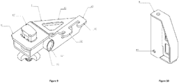
- Figure-9 : Perspective view of portable right lock assembly
- Figure-10 : Perspective view of container bearing assembly
- Figure-11 : Sectional perspective view of front lock assembly with pin at open position
- Figure-12 : Sectional perspective view of front lock assembly with pin at closed position
- Figure-13 : Perspective view of bump stop
-
- 1. 45 ft tunnel container
- 1.1. Frontal locking hole
- 2. Front lock middle profile assembly
- 2.1. Front lock profile U gap
- 2.1.1. Inner bearing seat
- 2.1.2. Outer bearing seat
- 2.2. Middle profile
- 2.3. Bearing assembly seat
- 2.4. Bump stop vertical slide housing
- 2.5. Bump stop bottom bearing
- 2.5.1. Horizontal slide housing
- 2.5.2. Bottom position seat
- 2.5.3. Top position seat
- 2.1. Front lock profile U gap
- 3. Front lock left profile assembly
- 3.1. Front lock horizontal pin
- 3.2. Front lock vertical pin
- 3.3. Handle
- 3.3.1. Middle pin hole
- 3.3.2. Front pin hole
- 3.3.3. Rear pin hole
- 3.3.4. Handle seat
- 3.3.5. Handle bumper
- 3.4. Front lock profile outer bumper
- 3.4.1. Horizontal hole
- 3.4.2. Vertical hole
- 3.4.3. Bumper seat
- 3.5. Front lock profile outer top sheet
- 3.5.1. Top sheet gap
- 3.6. Front lock profile
- 3.6.1. Vertical pin hole
- 3.6.2. Handle guide pin
- 3.6.3. Profile gap
- 3.6.4. Angled gap
- 3.7. Front lock profile inner support sheet
- 4. Front lock right profile assembly
- 5. 40 ft tunnel container
- 5.1. Frontal locking hole
- 5.2. Bottom locking hole
- 6. Portable left lock assembly
- 6.1. Container lock
- 6.1.1. Locking pin
- 6.2. Radial bearing
- 6.2.1. Radial bearing seat
- 6.3. Rear sheet
- 6.3.1. Portable lock teeth
- 6.4. Support sheet
- 6.1. Container lock
- 7. Portable right lock assembly
- 8. Bearing assembly
- 8.1. Bearing assembly hole
- 9. Bump stop
- 9.1. Bearing hole
- 9.2. Positioning hole
- 10. Moving pin assembly
- 10.1. Moving pin
- 11. Bump stop pin
- In this detailed description, preferred setups of the product with property of being able to be used as front lock mechanism of container carrier vehicles has been described solely for the purpose to better clarify the subject without placing any limitations.
- The mechanism consists of 45 ft tunnel container (1), front lock middle profile assembly (2), front lock left profile assembly (3), front lock right profile assembly (4), 40 ft tunnel container (5), portable left lock assembly (6), portable right lock assembly (7), bearing assembly (8), bump stop (9), moving pin assembly (10) and bump stop bin (11).
- 45 ft tunnel containers (1) are box-body structures which are used for road transportation performed at roads and ports with containers and usually carry pallet and partial loads and have a length of 45 ft with loading tunnel. The frontal locking hole (1.1) on 45 ft tunnel containers (1) are sockets into which the front lock horizontal pins (3.1) are inserted. The container is secured from the front as the said pin enters the frontal locking hole (1.1)
- The mechanism is primarily formed by assembly via mounting of front lock middle profile assembly (2), left profile assembly (3), front lock right profile assembly (4), front lock horizontal pin (3.1), front lock vertical pin (3.2), handle (3.3), portable left lock assembly (6), portable right lock assembly (7), bearing assembly (8) and bump stop pin (11) and assembly via welding of bump stop (9) and moving pin assembly.
- Front lock middle profile assembly (2) is the part where front lock right and left profile assemblies (3, 4) are mounted. Front lock right and left profile assemblies (3, 4) are mounted within the front lock middle profile assembly (2) and move inside-outside within the front lock middle profile assembly (2). It is the main body part where all mechanisms are mounted.
- Front lock middle profile assembly (2) consists of front lock profile U gap (2.1), middle profile (2.2), bearing assembly seat (2.3), bump stop vertical slide housing (2.4) and bump stop bottom bearing (2.5).
- Stop bump vertical slide housing (2.4) is the space allowing the stop bump (9) to slide through the middle profile (2.2). It moves left and right, front and back by passing through the stop bump (9).
- Stop bump bottom seat (2.5) is the part on which the stop bump (9) is secured and slides. Stop bump horizontal slide housing (2.5.1) consists of stop bump bottom position seat (2.5.2) and stop bump top position seat (2.5.3).
- Stop bump horizontal slide housing (2.5.1) allows the stop bump (9) to be secured on the stop bump bottom seat (2.5) in 2 different positions thanks to its shape.
- Front lock middle profile assembly (2) is formed by assembling the middle profile (2.2), bearing assembly seat (2.3), stop bump bottom seat (2.5) and moving pin assembly (10) elements by means of welding.
- Middle profile (2.2) has gaps named front lock profile U gap (2.1) and stop bump vertical slide housing (2.4). Front lock vertical pin (3.2) can move in "U" form within the front lock profile U gap (2.1). Front lock profile U gap (2.1) is the gap shaped U where the front lock vertical pin (3.2) is mounted. Due to its U shape, it allows the front lock vertical pin (3.2) to be in two different positions.
- Front lock profile U gap (2.1) incorporates front lock profile inner bearing seat (2.1.1) and front lock profile outer bearing seat (2.1.2).
- Front lock profile inner bearing seat (2.1.1) allows mounting the parts of front lock right and left profile assemblies (3, 4) for transportation of 45 ft tunnel (1) and 40 ft non-tunnel containers. Front lock profile outer bearing seat (2.1.2) allows mounting the parts of front lock right and left profile assemblies (3, 4) for transportation of 40 ft tunnel containers (5).
- Front lock right and left profile assembly (3, 4) is the part which can go in/out to front lock middle profile assembly (2). It can go in/out at the said profile depending on the type of transported container.
- While the front lock vertical pin (3.2) element is mounted in the front lock profile inner bearing seat (2.1.1), front lock left profile assembly (3) and front lock right profile assembly (4) are inserted in the front lock middle profile assembly (2). While the front lock vertical pin (3.2) element is mounted in the front lock profile outer bearing seat (2.1.2), front lock left profile assembly (3) and front lock right profile assembly (4) are mounted in the front lock middle profile assembly (2) with a bit sticking out. Front lock vertical pin (3.2) is the part moving between 2 different positions within front lock middle profile assembly (2.1).
- Handle (3.3) is the part where the front lock horizontal pin (3.1) is mounted. Handle (3.3) consists of handle middle pin hole (3.3.1), handle front pin hole (3.3.2), handle rear pin hole (3.3.3), handle seat (3.3.4) and handle bump stop (3.3.5).
- Handle (3.3) and front lock horizontal pin (3.1) is mounted on each other through handle front pin hole (3.3.2). Handle (3.3) is connected with front lock profile (3.6) via the rear pin hole (3.3.3) located on the former and handle guide pin (3.6.2) welded on the latter. Thus when the handle (3.3) is pulled and pushed, it can pivot on the handle rear pin hole (3.3.3) and handle guide pin (3.6.2).
- By pulling or pushing the handle (3.3) by hand thanks to handle seat (3.3.4) gap, front lock horizontal pin (3.1) can be moved in linear path inside/outside within the front lock profile outer bumper (3.4). In order for the front lock horizontal pin (3.1) and handle (3.3) to be mounted in the front lock profile outer bumper (3.4), the handle middle pin hole (3.3.1) and the moving pin assembly (10) welded on front lock profile outer bumper (3.4) are used. Moving pin assembly (10) is moved to open position and thus the middle pin (10.1) is released from handle middle pin hole (3.3.1). By pulling the handle (3.3) from handle seat (3.3.4), front lock horizontal pin (3.1) is pulled inwards in linear path within the front lock profile outer bumper (3.4). The front lock horizontal pin (3.1) can thus be inserted to/ejected from 45 ft tunnel container (1) 45 ft tunnel frontal locking hole (1.1) and 40 ft tunnel container (5) 40 ft tunnel frontal locking hole (5.1). Thus, 45 ft tunnel container (1) and 40 ft tunnel container (5) is secured or released by front lock horizontal pin (3.1). Middle pin hole (3.3.1) is secured on front lock right and left profile assembly (3, 4) with moving pin assembly (10).
- When handle (3.3) is pulled, handle bumper (3.3.5) hits the middle profile (2.2) inner surface and the front lock horizontal pin (3.1) is stopped. In other words, it allows the front lock horizontal pin (3.1) to move at required distance within the front lock profile outer bumper (3.4).
- Front lock left profile assembly (3) is the part which can go in/out to front lock middle profile assembly (2). It can go in/out at the said profile depending on the type of transported container.
- Front lock left profile assembly (3) consists of front lock horizontal pin (3.1), front lock vertical pin (3.2), handle (3.3), front lock profile outer bumper (3.4), front lock profile top sheet (3.5), front lock profile (3.6) and front lock profile inner support sheet (3.7). Front lock left profile assembly (3) is formed by assembling front lock profile outer bumper (3.4), front lock profile top sheet (3.5), front lock profile (3.6), front lock guide pin (3.6.2) and front lock profile inner support sheet (3.7) by means of welding.
- Front lock profile outer bumper (3.4) is the part on which the front lock horizontal pin (3.19 and handle (3.3) is secured. Front lock profile outer bumper (3.4) incorporates front lock profile outer bumper horizontal hole (3.4.1), front lock profile outer bumper vertical hole (3.4.2) and front lock profile outer bumper seat (3.4.3). Front lock horizontal pin (3.1) is inserted into front lock profile outer bumper horizontal hole (3.4.1). Moving pin assembly (10) is inserted into front lock profile outer bumper vertical hole (3.4.2). Handle (3.3) is inserted into front lock profile outer bumper seat (3.4.3).
- Front lock profile top sheet (3.5) incorporates front lock profile top sheet gap (3.5.1). Portable lock teeth (6.3.1) which is sub-part of portable left lock assembly (6) and portable right lock assembly (7) is inserted into front lock profile top sheet gap (3.5.1).
- Front lock profile (3.6) is the part which can go in/out to front lock middle profile assembly (2). Front lock profile (3.6) incorporates front lock vertical pin hole (3.6.1), front lock profile hap (3.6.3) and front lock profile angled gap (3.6.4). Front lock vertical pin (3.2) is mounted in front lock vertical pin hole (3.6.1). Front lock profile gap (3.6.3) allows creation of a gap until the bump stop (9) is mounted between, when the front lock right and left profile assemblies (3.4) are within the front lock middle profile assembly (2). Front lock profile angled gap (3.6.4) is a gap created in order to allow manual pushing/pulling of handle (3.3) through front lock right and left profile assemblies (3.4) and due to regulation and is mounted in front lock right and left profile assemblies (3.4) by handle (3.3) guide pin (3.6.2) and rear pin hole (3.3.3).
- Front lock profile inner support sheet (3.7) is the part on which stop bump bears from front. This part also serves as support.
- Front lock right profile assembly (4) is formed by assembling front lock profile outer bumper (3.4), front lock profile top sheet (3.5), front lock profile (3.6), front lock guide pin (3.6.2) and front lock profile inner support sheet (3.7) by means of welding.
- Front lock profile outer bumper (3.4) incorporates front lock profile outer bumper horizontal hole (3.4.1), front lock profile outer bumper vertical hole (3.4.2) and front lock profile outer bumper seat (3.4.3).
- Front lock horizontal pin (3.1) is inserted into front lock profile outer bumper horizontal hole (3.4.1). Moving pin assembly (10) is inserted into front lock profile outer bumper vertical hole (3.4.2). Handle (3.3) is inserted into front lock profile outer bumper seat (3.4.3).
- Front lock profile top sheet (3.5) is the part where the portable left lock assembly (6) and portable right lock assembly (7) are mounted. Front lock profile top sheet (3.5) incorporates front lock profile top sheet gap (3.5.1). Portable lock teeth (6.3.1) which is sub-part of portable left lock assembly (6) and portable right lock assembly (7) is inserted into front lock profile top sheet gap (3.5.1).
- Front lock profile (3.6) incorporates front lock vertical pin hole (3.6.1), front lock profile hap (3.6.3) and front lock profile angled gap (3.6.4). Front lock vertical pin (3.2) is mounted in front lock vertical pin hole (3.6.1). Front lock profile gap (3.6.3) allows creation of a gap until the bump stop (9) is mounted between, when the front lock right and left profile assemblies (3.4) are within the front lock middle profile assembly (2). Front lock profile angled gap (3.6.4) is a gap created in order to allow manual pushing/pulling of handle (3.3) through front lock right and left profile assemblies (3.4) and due to regulation and is mounted in front lock right and left profile assemblies (3.4) by handle (3.3) handle guide pin (3.6.2) and rear pin hole (3.3.3).
- Front lock profile inner support sheet (3.7) is the part on which stop bump bears from front. This part also serves as support.
- Portable left lock assembly (6) is only used for 40 ft tunnel container loading and non-tunnel loading. In case 40 ft tunnel container (5) is to be transported as non-tunnel, portable left lock assembly (6) is secured on front lock left profile assembly (3) when the front lock vertical pin (3.2) is positioned at front lock profile inner bearing seat (2.1.1).
- Portable left lock assembly (6) is formed by assembly via welding of the container lock (6.1), portable lock radial bearing (6.2), portable lock rear sheet (6.3) and portable lock support sheet (6.4).
- Container lock (6.1) incorporates container lock pin (6.1.1). Container lock pin (6.1.1) allows 40 ft tunnel containers (5) to be secured to portable left lock assembly (6) by entering the 40 ft tunnel container bottom locking hole (5.2) which is bottom part of 40 ft tunnel container (5).
- Portable lock radial bearing (6.2) has the portable lock radial bearing seat (6.2.1). Portable lock radial bearing seat (6.2.1), by means entrance of front lock horizontal pin (3.1) thereto, allows the portable left lock assembly (6) to be secured and moved and supports it with bearings.
- Portable lock rear sheet (6.3) has the portable lock teeth (6.3.1). Portable lock teeth (6.3.1) is the male of the front lock profile top sheet gap (3.5.1) which is bottom part of front lock right and left profile assemblies (3, 4).
- Front lock profile top sheet gap (3.5.1) and portable lock teeth (6.3.1) engage and allow the front lock left profile assembly (3) to interlock with portable left lock assembly (6). Portable lock support sheet (6.4) serves as reinforcement within portable left lock assembly (6) and increases strength of portable left lock assembly (6).
- Portable left lock assembly (6) and portable right lock assembly (7) are removable. They are used only for 40 ft tunnel container non-tunnel loadings. In case 40 ft tunnel container (5) is to be transported as non-tunnel, portable right lock assembly (7) is secured on front lock right profile assembly (4) when the front lock vertical pin (3.2) is positioned at front lock profile inner bearing seat (2.1.1).
- Portable right lock assembly (7) is formed by assembly via welding of the container lock (6.1), portable lock radial bearing (6.2), portable lock rear sheet (6.3) and portable lock support sheet (6.4).
- Container lock (6.1) incorporates container lock pin (6.1.1). Container lock pin (6.1.1) allows 40 ft tunnel containers (5) to be secured to portable left lock assembly (6) by entering the 40 ft tunnel container bottom locking hole (5.2) which is bottom part of 40 ft tunnel container (5).
- Portable lock radial bearing (6.2) has the portable lock radial bearing seat (6.2.1). Portable lock radial bearing seat (6.2.1), through entrance of front lock horizontal pin (3.1) thereto, allows the portable left lock assembly (6) to be secured and moved and supports it with bearings.
- Portable lock rear sheet (6.3) has the portable lock teeth (6.3.1). Portable lock teeth (6.3.1) is the male of the front lock profile top sheet gap (3.5.1) which is bottom part of front lock right and left profile assemblies (3, 4).
- Front lock profile top sheet gap (3.5.1) and portable lock teeth (6.3.1) engage and allow the front lock right profile assembly (4) to interlock with portable right lock assembly (7). Portable lock support sheet (6.4) serves as reinforcement within portable right lock assembly (7) and increases strength of portable right lock assembly (7).
- Bearing assembly (8) allows the containers to be secured without damaging the parts during loading and unloading. Bearing assembly (8) enters to bearing assembly seat (2.3). Bearing assembly (8) incorporates bearing assembly hole (8.1). Bearing assembly hole (2.3) is secured and mounted with the moving pin assembly (10) welded thereon. It can be mounted or dismounted as required by means of moving pin assembly (10).
- Stop bump (9) incorporates stop bump bearing hole (9.1) and stop bump positioning hole (9.2). Stop bump pins are mounted in stop bump bearing hole (9.1) holes. Moving pin assembly (10) is welded on stop bump positioning hole (9.2). Stop bump pin (11) is then inserted to stop bump vertical slide (2.5.1) seat. Stop bump pin (11) can move left and right in stop bump vertical slide housing (2.5.1). Stop bump bottom position seat (2.5.2) and stop bump top position seat (2.5.3) are used to position and secure this movement as required.
- Stop bump (9) is the part allowing the front lock left profile assembly (3) and front lock right profile assembly (4) to be secured frontally in front lock middle profile (2). Stop bump (9) passes through stop bump vertical slide housing (2.4). Then, the stop bump (9) and the moving pin assembly (10) is welded together. This new welded structure can move right and left, front and rear with this new form inside the stop bump vertical slide housing (2.4).
- In order for bump stop (9) and moving pin assembly (10) to be secured and moved with required positions; stop bump bottom bearing (2.5) has bump stop horizontal slide housing (2.5.1), bump stop bottom position seat (2.5.2) and bump stop top position seat (2.5.3) gaps.
- When the bump stop (9) and moving pin assembly (10) are secured by means of moving pin (10.1) through bump stop bottom position seat (2.5.2), front lock left profile assembly (3) and front lock right profile assembly (4) cannot move forward and are secured.
- When the bump stop (9) and moving pin assembly (10) are secured through bump stop bottom position seat (2.5.2), there will not be any gap between the front lock left profile assembly (3) and front lock right profile assembly (4) and bump stop (9).
- When the bump stop (9) and moving pin assembly (10) are secured through bump stop top position seat (2.5.3), there will be gap between the front lock left profile assembly (3) and front lock right profile assembly (4) and bump stop (9).
- When the bump stop (9) and moving pin assembly (10) are secured by means of moving pin (10.1) through bump stop bottom position seat (2.5.3), front lock left profile assembly (3) and front lock right profile assembly (4) can move forward. The amount of this movement is decided by the form of front lock profile U gap (2.1) and front lock profile gap (3.6.3).
- Moving pin assembly (10) secures the stop bump (9) to stop bump bottom bearing (2.5), handle (3.3) to front lock left profile assembly (3), handle (3.3) to front lock right profile assembly (4), bearing assembly (8) to bearing assembly seat (2.3).
- Moving pin assembly (10) incorporates moving pin (10.1) part and this part protrudes from the moving pin assembly (10) as much as to be able to perform bearing function. When moving pin assembly (10) is pivoted, moving pin (10.1) bottom part moves into moving pin assembly (10). When repeating motion pin assembly (10) returns to its former position, the moving pin (10.1) once again protrudes from the repeating motion pin assembly (10).
- Stop bump pin (11) is mounted on stop bump (9). Then, Stop bump pin (11) is then passed through the stop bump vertical slide (2.5.1) seat. Thus, it is enabled for stop bump (9) to slide in stop bump horizontal slide housing (2.5.1) with the form of this housing.
Claims (15)
- A front lock mechanism for transport vehicles for transportation with 45 ft tunnel container (1) and 40 ft tunnel container (5) at roads and ports and characterized in comprising;• a front lock middle profile assembly (2) in connection with a front lock left profile assembly (3) and a front lock right profile assembly (4),• the front lock left profile assembly (3) able to enter/exit the said front lock middle profile assembly (2),• the front lock right profile assembly (4) able to enter/exit the said front lock middle profile assembly (2),• a portable left lock assembly (6) in contact with the said front lock left profile assembly (3) and allowing transportation of 40 ft non-tunnel containers,• a portable right lock assembly (7) in contact with the said front lock right profile assembly (4) and allowing transportation of 40 ft non-tunnel containers,• a bearing assembly (8) in contact with a moving pin assembly (10) and allowing the containers to be secured during loading and unloading,• a stop bump (9) allowing the said front lock left profile assembly (3) and said front lock right profile assembly (4) to be secured in the front lock middle profile (2),• the moving pin assembly (10) in contact with the said stop bump (9),• A stop bump pin (11) in contact with the said stop bump (9).
- A front lock middle profile assembly (2) according to Claim 1 and characterized in comprising- a front lock profile U gap (2.1) comprising a front lock profile inner bearing seat (2.1.1) and a front lock profile outer bearing seat (2.1.2),- a middle profile (2.2),- a bearing assembly seat (2.3),- a bump stop vertical slide housing (2.4) through which the stop bump passes and moves- a bump stop bottom bearing (2.5) on which the stop bump is secured and slides; and which is comprising a stop bump horizontal slide housing (2.5.1), a stop bump bottom position seat (2.5.2) and a stop bump top position seat (2.5.3).
- A front lock profile U gap (2.1) according to Claims 1 or 2 and characterized in comprising a "U" form moving front lock vertical pin (3.2).
- A front lock left profile assembly (3) according to Claim 1 and characterized in comprising a handle (3.3) to which a front lock horizontal pin (3.1) is connected.
- A handle (3.3) according to Claims 1 or 4 and characterized in comprising a handle middle pin hole (3.3.1) secured to said front lock left profile assembly (3) and said front lock right profile assembly (4) via moving said pin assembly (10), a handle front pin hole (3.3.2), a handle rear pin hole (3.3.3), a handle seat (3.3.4) and a handle bump stop (3.3.5).
- A front lock left profile assembly (3) according to Claim 1 or 4 and characterized in comprising a front lock profile outer bumper (3.3) to which the front lock horizontal pin (3.1) and the handle (3.3) are secured and which is comprising a front lock profile outer bumper horizontal hole (3.4.1), front lock profile outer bumper vertical hole (3.4.2) and front lock profile outer bumper seat (3.4.3).
- A front lock left profile assembly (3) according to Claim 1 and characterized in comprising a front lock profile top sheet (3.5) to which the portable left lock assembly (6) and the portable right lock assembly (7) are mounted and which is comprising a front lock profile top sheet gap (3.5.1) into which the a portable lock teeth (6.3.1) enters.
- A left profile assembly (3) according to Claim 1 and characterized in comprising a front lock profile (3.6) which can enter/exit the front lock middle profile assembly (2).
- A front lock profile (3.6) according to Claims 1 or 8 and characterized in comprising a front lock vertical pin hole (3.6.1), a front lock profile hap (3.6.3) and a front lock profile angled gap (3.6.4).
- A front lock left profile assembly (3) according to Claim 1 and characterized in comprising a front lock profile inner support sheet (3.7) to which the stop bump bears from front.
- A portable left lock assembly (6) according to Claim 1 and characterized in that it is formed by assembly via welding of a container lock (6.1), a portable lock radial bearing (6.2), a portable lock rear sheet (6.3) with portable lock teeth and a portable lock support sheet (6.4).
- A portable lock radial bearing (6.2) according to Claim 1 or 4 or 11 and characterized in comprising a portable lock radial bearing seat (6.2.1) which, by means of entry of the front lock horizontal pin (3.1) thereto, allows the portable left lock assembly (6) to be secured and moved.
- A front lock mechanism for carrier vehicles according to Claim 1 or 2 and characterized in comprising a bearing assembly (8) preventing damage on parts during container loading and unloading and entering to the bearing assembly seat (2.3).
- A stop bump (9) according to Claims 1 and characterized in comprising a stop bump bearing hole (9.1) and a stop bump positioning hole (9.2).
- A front lock mechanism for carrier vehicles according to Claim 1 or 2 and characterized in comprising the stop bump pin (11) secured to the stop bump by passing through the stop bump horizontal slide housing (2.5.1).
Applications Claiming Priority (1)
| Application Number | Priority Date | Filing Date | Title |
|---|---|---|---|
| TR2016/18517A TR201618517A2 (en) | 2016-12-14 | 2016-12-14 | Front locking mechanism for container transporting vehicles |
Publications (2)
| Publication Number | Publication Date |
|---|---|
| EP3335934A1 true EP3335934A1 (en) | 2018-06-20 |
| EP3335934B1 EP3335934B1 (en) | 2020-03-25 |
Family
ID=60673281
Family Applications (1)
| Application Number | Title | Priority Date | Filing Date |
|---|---|---|---|
| EP17206636.7A Active EP3335934B1 (en) | 2016-12-14 | 2017-12-12 | Front lock mechanism for container carrier vehicles |
Country Status (2)
| Country | Link |
|---|---|
| EP (1) | EP3335934B1 (en) |
| TR (1) | TR201618517A2 (en) |
Citations (5)
| Publication number | Priority date | Publication date | Assignee | Title |
|---|---|---|---|---|
| NL1019712C1 (en) * | 2002-01-08 | 2003-07-09 | Broshuis B V | Container locking arrangement has components which are exchangeable and involves support beam from which it is releasable, its components being fitted on support arms displaceable out of support beam |
| ES2228215A1 (en) * | 2002-06-28 | 2005-04-01 | Schulz Iberica, S.A. | Multipurpose modular corner for chassis carrying horizontal container, has fixed module and mobile module fixed with groove coupling module and pins through bolt that is provided on front part and bottom part of horizontal container |
| EP1637393A2 (en) | 2004-09-18 | 2006-03-22 | Jost-Werke GmbH & Co. KG | Mounting beam for securing containers on vehicles |
| EP1777103B1 (en) | 2005-10-21 | 2009-09-23 | Fahrzeugwerk Bernard Krone GmbH | Universal locking device for containers with different sizes on a vehicle |
| EP2765029A1 (en) * | 2013-02-08 | 2014-08-13 | HFM Patenten BV | A trailer for use in road haulage and a method for using the trailer |
-
2016
- 2016-12-14 TR TR2016/18517A patent/TR201618517A2/en unknown
-
2017
- 2017-12-12 EP EP17206636.7A patent/EP3335934B1/en active Active
Patent Citations (5)
| Publication number | Priority date | Publication date | Assignee | Title |
|---|---|---|---|---|
| NL1019712C1 (en) * | 2002-01-08 | 2003-07-09 | Broshuis B V | Container locking arrangement has components which are exchangeable and involves support beam from which it is releasable, its components being fitted on support arms displaceable out of support beam |
| ES2228215A1 (en) * | 2002-06-28 | 2005-04-01 | Schulz Iberica, S.A. | Multipurpose modular corner for chassis carrying horizontal container, has fixed module and mobile module fixed with groove coupling module and pins through bolt that is provided on front part and bottom part of horizontal container |
| EP1637393A2 (en) | 2004-09-18 | 2006-03-22 | Jost-Werke GmbH & Co. KG | Mounting beam for securing containers on vehicles |
| EP1777103B1 (en) | 2005-10-21 | 2009-09-23 | Fahrzeugwerk Bernard Krone GmbH | Universal locking device for containers with different sizes on a vehicle |
| EP2765029A1 (en) * | 2013-02-08 | 2014-08-13 | HFM Patenten BV | A trailer for use in road haulage and a method for using the trailer |
Also Published As
| Publication number | Publication date |
|---|---|
| TR201618517A2 (en) | 2017-02-21 |
| EP3335934B1 (en) | 2020-03-25 |
Similar Documents
| Publication | Publication Date | Title |
|---|---|---|
| CN108200768B (en) | folding container | |
| EP2671814A1 (en) | Adaptor pallet | |
| CN109476352A (en) | Improved semi-trailer | |
| JP5451686B2 (en) | Semi-trailer body structure | |
| EP3335934B1 (en) | Front lock mechanism for container carrier vehicles | |
| DE102009025665A1 (en) | Transport device i.e. shopping trolley, for use with motor vehicle, has gear legs, and support beams height-adjustably arranged along respective legs at end region of each leg, where legs are mounted around pivot angle of specific degrees | |
| JP2005112473A (en) | Device for fixing and/or positioning object in transportation container and transportation container adopting the same | |
| DE202010004732U1 (en) | Duty transport vehicle | |
| CN112498490A (en) | Semitrailer and frame thereof | |
| JP2012001139A (en) | Loading platform, trailer, and rack | |
| JP5085989B2 (en) | Container-loading semi-trailer | |
| US3628222A (en) | Latching mechanism | |
| JP2012201130A (en) | Vehicle body structure of semi-trailer | |
| EP3738828B1 (en) | Foldable automatic twistlock arrangement | |
| JP4726565B2 (en) | Aircraft pallet equipment | |
| US9738464B1 (en) | System and method for protecting containers from damage during loading | |
| JP4919930B2 (en) | Vehicle with sloping platform | |
| US20020000736A1 (en) | Horizontal positioning of dump truck tailgate | |
| CN205738882U (en) | Collapsible container | |
| CN214001823U (en) | Semitrailer and frame thereof | |
| JP6223929B2 (en) | Container chassis transfer plate structure | |
| JP2008074143A (en) | Extendable container chassis | |
| CN213706592U (en) | Container, especially container for transporting goods | |
| DE102013018623B4 (en) | CHARGING DEVICE FOR VEHICLES | |
| CN211077138U (en) | Limiting device for logistics vehicle |
Legal Events
| Date | Code | Title | Description |
|---|---|---|---|
| PUAI | Public reference made under article 153(3) epc to a published international application that has entered the european phase |
Free format text: ORIGINAL CODE: 0009012 |
|
| STAA | Information on the status of an ep patent application or granted ep patent |
Free format text: STATUS: THE APPLICATION HAS BEEN PUBLISHED |
|
| AK | Designated contracting states |
Kind code of ref document: A1 Designated state(s): AL AT BE BG CH CY CZ DE DK EE ES FI FR GB GR HR HU IE IS IT LI LT LU LV MC MK MT NL NO PL PT RO RS SE SI SK SM TR |
|
| AX | Request for extension of the european patent |
Extension state: BA ME |
|
| STAA | Information on the status of an ep patent application or granted ep patent |
Free format text: STATUS: REQUEST FOR EXAMINATION WAS MADE |
|
| 17P | Request for examination filed |
Effective date: 20181001 |
|
| RBV | Designated contracting states (corrected) |
Designated state(s): AL AT BE BG CH CY CZ DE DK EE ES FI FR GB GR HR HU IE IS IT LI LT LU LV MC MK MT NL NO PL PT RO RS SE SI SK SM TR |
|
| GRAP | Despatch of communication of intention to grant a patent |
Free format text: ORIGINAL CODE: EPIDOSNIGR1 |
|
| STAA | Information on the status of an ep patent application or granted ep patent |
Free format text: STATUS: GRANT OF PATENT IS INTENDED |
|
| RIC1 | Information provided on ipc code assigned before grant |
Ipc: B60P 1/64 20060101AFI20191129BHEP Ipc: B60P 7/13 20060101ALI20191129BHEP |
|
| INTG | Intention to grant announced |
Effective date: 20191216 |
|
| GRAS | Grant fee paid |
Free format text: ORIGINAL CODE: EPIDOSNIGR3 |
|
| GRAA | (expected) grant |
Free format text: ORIGINAL CODE: 0009210 |
|
| STAA | Information on the status of an ep patent application or granted ep patent |
Free format text: STATUS: THE PATENT HAS BEEN GRANTED |
|
| AK | Designated contracting states |
Kind code of ref document: B1 Designated state(s): AL AT BE BG CH CY CZ DE DK EE ES FI FR GB GR HR HU IE IS IT LI LT LU LV MC MK MT NL NO PL PT RO RS SE SI SK SM TR |
|
| REG | Reference to a national code |
Ref country code: GB Ref legal event code: FG4D |
|
| REG | Reference to a national code |
Ref country code: AT Ref legal event code: REF Ref document number: 1248205 Country of ref document: AT Kind code of ref document: T Effective date: 20200415 Ref country code: IE Ref legal event code: FG4D |
|
| REG | Reference to a national code |
Ref country code: DE Ref legal event code: R096 Ref document number: 602017013563 Country of ref document: DE |
|
| PG25 | Lapsed in a contracting state [announced via postgrant information from national office to epo] |
Ref country code: RS Free format text: LAPSE BECAUSE OF FAILURE TO SUBMIT A TRANSLATION OF THE DESCRIPTION OR TO PAY THE FEE WITHIN THE PRESCRIBED TIME-LIMIT Effective date: 20200325 Ref country code: NO Free format text: LAPSE BECAUSE OF FAILURE TO SUBMIT A TRANSLATION OF THE DESCRIPTION OR TO PAY THE FEE WITHIN THE PRESCRIBED TIME-LIMIT Effective date: 20200625 Ref country code: FI Free format text: LAPSE BECAUSE OF FAILURE TO SUBMIT A TRANSLATION OF THE DESCRIPTION OR TO PAY THE FEE WITHIN THE PRESCRIBED TIME-LIMIT Effective date: 20200325 |
|
| PG25 | Lapsed in a contracting state [announced via postgrant information from national office to epo] |
Ref country code: HR Free format text: LAPSE BECAUSE OF FAILURE TO SUBMIT A TRANSLATION OF THE DESCRIPTION OR TO PAY THE FEE WITHIN THE PRESCRIBED TIME-LIMIT Effective date: 20200325 Ref country code: LV Free format text: LAPSE BECAUSE OF FAILURE TO SUBMIT A TRANSLATION OF THE DESCRIPTION OR TO PAY THE FEE WITHIN THE PRESCRIBED TIME-LIMIT Effective date: 20200325 Ref country code: SE Free format text: LAPSE BECAUSE OF FAILURE TO SUBMIT A TRANSLATION OF THE DESCRIPTION OR TO PAY THE FEE WITHIN THE PRESCRIBED TIME-LIMIT Effective date: 20200325 Ref country code: GR Free format text: LAPSE BECAUSE OF FAILURE TO SUBMIT A TRANSLATION OF THE DESCRIPTION OR TO PAY THE FEE WITHIN THE PRESCRIBED TIME-LIMIT Effective date: 20200626 Ref country code: BG Free format text: LAPSE BECAUSE OF FAILURE TO SUBMIT A TRANSLATION OF THE DESCRIPTION OR TO PAY THE FEE WITHIN THE PRESCRIBED TIME-LIMIT Effective date: 20200625 |
|
| REG | Reference to a national code |
Ref country code: NL Ref legal event code: MP Effective date: 20200325 |
|
| REG | Reference to a national code |
Ref country code: LT Ref legal event code: MG4D |
|
| PG25 | Lapsed in a contracting state [announced via postgrant information from national office to epo] |
Ref country code: NL Free format text: LAPSE BECAUSE OF FAILURE TO SUBMIT A TRANSLATION OF THE DESCRIPTION OR TO PAY THE FEE WITHIN THE PRESCRIBED TIME-LIMIT Effective date: 20200325 |
|
| PG25 | Lapsed in a contracting state [announced via postgrant information from national office to epo] |
Ref country code: SK Free format text: LAPSE BECAUSE OF FAILURE TO SUBMIT A TRANSLATION OF THE DESCRIPTION OR TO PAY THE FEE WITHIN THE PRESCRIBED TIME-LIMIT Effective date: 20200325 Ref country code: RO Free format text: LAPSE BECAUSE OF FAILURE TO SUBMIT A TRANSLATION OF THE DESCRIPTION OR TO PAY THE FEE WITHIN THE PRESCRIBED TIME-LIMIT Effective date: 20200325 Ref country code: IS Free format text: LAPSE BECAUSE OF FAILURE TO SUBMIT A TRANSLATION OF THE DESCRIPTION OR TO PAY THE FEE WITHIN THE PRESCRIBED TIME-LIMIT Effective date: 20200725 Ref country code: CZ Free format text: LAPSE BECAUSE OF FAILURE TO SUBMIT A TRANSLATION OF THE DESCRIPTION OR TO PAY THE FEE WITHIN THE PRESCRIBED TIME-LIMIT Effective date: 20200325 Ref country code: LT Free format text: LAPSE BECAUSE OF FAILURE TO SUBMIT A TRANSLATION OF THE DESCRIPTION OR TO PAY THE FEE WITHIN THE PRESCRIBED TIME-LIMIT Effective date: 20200325 Ref country code: PT Free format text: LAPSE BECAUSE OF FAILURE TO SUBMIT A TRANSLATION OF THE DESCRIPTION OR TO PAY THE FEE WITHIN THE PRESCRIBED TIME-LIMIT Effective date: 20200818 Ref country code: EE Free format text: LAPSE BECAUSE OF FAILURE TO SUBMIT A TRANSLATION OF THE DESCRIPTION OR TO PAY THE FEE WITHIN THE PRESCRIBED TIME-LIMIT Effective date: 20200325 Ref country code: SM Free format text: LAPSE BECAUSE OF FAILURE TO SUBMIT A TRANSLATION OF THE DESCRIPTION OR TO PAY THE FEE WITHIN THE PRESCRIBED TIME-LIMIT Effective date: 20200325 |
|
| REG | Reference to a national code |
Ref country code: AT Ref legal event code: MK05 Ref document number: 1248205 Country of ref document: AT Kind code of ref document: T Effective date: 20200325 |
|
| REG | Reference to a national code |
Ref country code: DE Ref legal event code: R097 Ref document number: 602017013563 Country of ref document: DE |
|
| PG25 | Lapsed in a contracting state [announced via postgrant information from national office to epo] |
Ref country code: ES Free format text: LAPSE BECAUSE OF FAILURE TO SUBMIT A TRANSLATION OF THE DESCRIPTION OR TO PAY THE FEE WITHIN THE PRESCRIBED TIME-LIMIT Effective date: 20200325 Ref country code: DK Free format text: LAPSE BECAUSE OF FAILURE TO SUBMIT A TRANSLATION OF THE DESCRIPTION OR TO PAY THE FEE WITHIN THE PRESCRIBED TIME-LIMIT Effective date: 20200325 Ref country code: IT Free format text: LAPSE BECAUSE OF FAILURE TO SUBMIT A TRANSLATION OF THE DESCRIPTION OR TO PAY THE FEE WITHIN THE PRESCRIBED TIME-LIMIT Effective date: 20200325 Ref country code: AT Free format text: LAPSE BECAUSE OF FAILURE TO SUBMIT A TRANSLATION OF THE DESCRIPTION OR TO PAY THE FEE WITHIN THE PRESCRIBED TIME-LIMIT Effective date: 20200325 |
|
| PLBE | No opposition filed within time limit |
Free format text: ORIGINAL CODE: 0009261 |
|
| STAA | Information on the status of an ep patent application or granted ep patent |
Free format text: STATUS: NO OPPOSITION FILED WITHIN TIME LIMIT |
|
| PG25 | Lapsed in a contracting state [announced via postgrant information from national office to epo] |
Ref country code: PL Free format text: LAPSE BECAUSE OF FAILURE TO SUBMIT A TRANSLATION OF THE DESCRIPTION OR TO PAY THE FEE WITHIN THE PRESCRIBED TIME-LIMIT Effective date: 20200325 |
|
| 26N | No opposition filed |
Effective date: 20210112 |
|
| PG25 | Lapsed in a contracting state [announced via postgrant information from national office to epo] |
Ref country code: SI Free format text: LAPSE BECAUSE OF FAILURE TO SUBMIT A TRANSLATION OF THE DESCRIPTION OR TO PAY THE FEE WITHIN THE PRESCRIBED TIME-LIMIT Effective date: 20200325 |
|
| REG | Reference to a national code |
Ref country code: CH Ref legal event code: PL |
|
| PG25 | Lapsed in a contracting state [announced via postgrant information from national office to epo] |
Ref country code: MC Free format text: LAPSE BECAUSE OF FAILURE TO SUBMIT A TRANSLATION OF THE DESCRIPTION OR TO PAY THE FEE WITHIN THE PRESCRIBED TIME-LIMIT Effective date: 20200325 |
|
| PG25 | Lapsed in a contracting state [announced via postgrant information from national office to epo] |
Ref country code: IE Free format text: LAPSE BECAUSE OF NON-PAYMENT OF DUE FEES Effective date: 20201212 Ref country code: FR Free format text: LAPSE BECAUSE OF NON-PAYMENT OF DUE FEES Effective date: 20201231 Ref country code: LU Free format text: LAPSE BECAUSE OF NON-PAYMENT OF DUE FEES Effective date: 20201212 |
|
| PG25 | Lapsed in a contracting state [announced via postgrant information from national office to epo] |
Ref country code: LI Free format text: LAPSE BECAUSE OF NON-PAYMENT OF DUE FEES Effective date: 20201231 Ref country code: CH Free format text: LAPSE BECAUSE OF NON-PAYMENT OF DUE FEES Effective date: 20201231 |
|
| PGFP | Annual fee paid to national office [announced via postgrant information from national office to epo] |
Ref country code: DE Payment date: 20211126 Year of fee payment: 5 |
|
| PGFP | Annual fee paid to national office [announced via postgrant information from national office to epo] |
Ref country code: BE Payment date: 20211125 Year of fee payment: 5 |
|
| PG25 | Lapsed in a contracting state [announced via postgrant information from national office to epo] |
Ref country code: TR Free format text: LAPSE BECAUSE OF FAILURE TO SUBMIT A TRANSLATION OF THE DESCRIPTION OR TO PAY THE FEE WITHIN THE PRESCRIBED TIME-LIMIT Effective date: 20200325 Ref country code: MT Free format text: LAPSE BECAUSE OF FAILURE TO SUBMIT A TRANSLATION OF THE DESCRIPTION OR TO PAY THE FEE WITHIN THE PRESCRIBED TIME-LIMIT Effective date: 20200325 Ref country code: CY Free format text: LAPSE BECAUSE OF FAILURE TO SUBMIT A TRANSLATION OF THE DESCRIPTION OR TO PAY THE FEE WITHIN THE PRESCRIBED TIME-LIMIT Effective date: 20200325 |
|
| PG25 | Lapsed in a contracting state [announced via postgrant information from national office to epo] |
Ref country code: MK Free format text: LAPSE BECAUSE OF FAILURE TO SUBMIT A TRANSLATION OF THE DESCRIPTION OR TO PAY THE FEE WITHIN THE PRESCRIBED TIME-LIMIT Effective date: 20200325 Ref country code: AL Free format text: LAPSE BECAUSE OF FAILURE TO SUBMIT A TRANSLATION OF THE DESCRIPTION OR TO PAY THE FEE WITHIN THE PRESCRIBED TIME-LIMIT Effective date: 20200325 |
|
| GBPC | Gb: european patent ceased through non-payment of renewal fee |
Effective date: 20211212 |
|
| PG25 | Lapsed in a contracting state [announced via postgrant information from national office to epo] |
Ref country code: GB Free format text: LAPSE BECAUSE OF NON-PAYMENT OF DUE FEES Effective date: 20211212 |
|
| REG | Reference to a national code |
Ref country code: DE Ref legal event code: R119 Ref document number: 602017013563 Country of ref document: DE |
|
| REG | Reference to a national code |
Ref country code: BE Ref legal event code: MM Effective date: 20221231 |
|
| PG25 | Lapsed in a contracting state [announced via postgrant information from national office to epo] |
Ref country code: DE Free format text: LAPSE BECAUSE OF NON-PAYMENT OF DUE FEES Effective date: 20230701 |
|
| PG25 | Lapsed in a contracting state [announced via postgrant information from national office to epo] |
Ref country code: BE Free format text: LAPSE BECAUSE OF NON-PAYMENT OF DUE FEES Effective date: 20221231 |