EP3335858A1 - Verfahren zur additiven herstellung eines dreidimensionalen objekts - Google Patents
Verfahren zur additiven herstellung eines dreidimensionalen objekts Download PDFInfo
- Publication number
- EP3335858A1 EP3335858A1 EP17178987.8A EP17178987A EP3335858A1 EP 3335858 A1 EP3335858 A1 EP 3335858A1 EP 17178987 A EP17178987 A EP 17178987A EP 3335858 A1 EP3335858 A1 EP 3335858A1
- Authority
- EP
- European Patent Office
- Prior art keywords
- building material
- support structure
- produced
- additive
- layerwise selective
- Prior art date
- Legal status (The legal status is an assumption and is not a legal conclusion. Google has not performed a legal analysis and makes no representation as to the accuracy of the status listed.)
- Granted
Links
Images

Classifications
-
- B—PERFORMING OPERATIONS; TRANSPORTING
- B29—WORKING OF PLASTICS; WORKING OF SUBSTANCES IN A PLASTIC STATE IN GENERAL
- B29C—SHAPING OR JOINING OF PLASTICS; SHAPING OF MATERIAL IN A PLASTIC STATE, NOT OTHERWISE PROVIDED FOR; AFTER-TREATMENT OF THE SHAPED PRODUCTS, e.g. REPAIRING
- B29C67/00—Shaping techniques not covered by groups B29C39/00 - B29C65/00, B29C70/00 or B29C73/00
- B29C67/02—Moulding by agglomerating
- B29C67/04—Sintering
-
- B—PERFORMING OPERATIONS; TRANSPORTING
- B29—WORKING OF PLASTICS; WORKING OF SUBSTANCES IN A PLASTIC STATE IN GENERAL
- B29C—SHAPING OR JOINING OF PLASTICS; SHAPING OF MATERIAL IN A PLASTIC STATE, NOT OTHERWISE PROVIDED FOR; AFTER-TREATMENT OF THE SHAPED PRODUCTS, e.g. REPAIRING
- B29C64/00—Additive manufacturing, i.e. manufacturing of three-dimensional [3D] objects by additive deposition, additive agglomeration or additive layering, e.g. by 3D printing, stereolithography or selective laser sintering
- B29C64/40—Structures for supporting 3D objects during manufacture and intended to be sacrificed after completion thereof
-
- B—PERFORMING OPERATIONS; TRANSPORTING
- B22—CASTING; POWDER METALLURGY
- B22F—WORKING METALLIC POWDER; MANUFACTURE OF ARTICLES FROM METALLIC POWDER; MAKING METALLIC POWDER; APPARATUS OR DEVICES SPECIALLY ADAPTED FOR METALLIC POWDER
- B22F10/00—Additive manufacturing of workpieces or articles from metallic powder
-
- B—PERFORMING OPERATIONS; TRANSPORTING
- B22—CASTING; POWDER METALLURGY
- B22F—WORKING METALLIC POWDER; MANUFACTURE OF ARTICLES FROM METALLIC POWDER; MAKING METALLIC POWDER; APPARATUS OR DEVICES SPECIALLY ADAPTED FOR METALLIC POWDER
- B22F10/00—Additive manufacturing of workpieces or articles from metallic powder
- B22F10/20—Direct sintering or melting
- B22F10/28—Powder bed fusion, e.g. selective laser melting [SLM] or electron beam melting [EBM]
-
- B—PERFORMING OPERATIONS; TRANSPORTING
- B22—CASTING; POWDER METALLURGY
- B22F—WORKING METALLIC POWDER; MANUFACTURE OF ARTICLES FROM METALLIC POWDER; MAKING METALLIC POWDER; APPARATUS OR DEVICES SPECIALLY ADAPTED FOR METALLIC POWDER
- B22F10/00—Additive manufacturing of workpieces or articles from metallic powder
- B22F10/40—Structures for supporting workpieces or articles during manufacture and removed afterwards
- B22F10/43—Structures for supporting workpieces or articles during manufacture and removed afterwards characterised by material
-
- B—PERFORMING OPERATIONS; TRANSPORTING
- B22—CASTING; POWDER METALLURGY
- B22F—WORKING METALLIC POWDER; MANUFACTURE OF ARTICLES FROM METALLIC POWDER; MAKING METALLIC POWDER; APPARATUS OR DEVICES SPECIALLY ADAPTED FOR METALLIC POWDER
- B22F10/00—Additive manufacturing of workpieces or articles from metallic powder
- B22F10/40—Structures for supporting workpieces or articles during manufacture and removed afterwards
- B22F10/47—Structures for supporting workpieces or articles during manufacture and removed afterwards characterised by structural features
-
- B—PERFORMING OPERATIONS; TRANSPORTING
- B29—WORKING OF PLASTICS; WORKING OF SUBSTANCES IN A PLASTIC STATE IN GENERAL
- B29C—SHAPING OR JOINING OF PLASTICS; SHAPING OF MATERIAL IN A PLASTIC STATE, NOT OTHERWISE PROVIDED FOR; AFTER-TREATMENT OF THE SHAPED PRODUCTS, e.g. REPAIRING
- B29C64/00—Additive manufacturing, i.e. manufacturing of three-dimensional [3D] objects by additive deposition, additive agglomeration or additive layering, e.g. by 3D printing, stereolithography or selective laser sintering
- B29C64/10—Processes of additive manufacturing
- B29C64/141—Processes of additive manufacturing using only solid materials
- B29C64/153—Processes of additive manufacturing using only solid materials using layers of powder being selectively joined, e.g. by selective laser sintering or melting
-
- B—PERFORMING OPERATIONS; TRANSPORTING
- B33—ADDITIVE MANUFACTURING TECHNOLOGY
- B33Y—ADDITIVE MANUFACTURING, i.e. MANUFACTURING OF THREE-DIMENSIONAL [3D] OBJECTS BY ADDITIVE DEPOSITION, ADDITIVE AGGLOMERATION OR ADDITIVE LAYERING, e.g. BY 3D PRINTING, STEREOLITHOGRAPHY OR SELECTIVE LASER SINTERING
- B33Y10/00—Processes of additive manufacturing
-
- B—PERFORMING OPERATIONS; TRANSPORTING
- B33—ADDITIVE MANUFACTURING TECHNOLOGY
- B33Y—ADDITIVE MANUFACTURING, i.e. MANUFACTURING OF THREE-DIMENSIONAL [3D] OBJECTS BY ADDITIVE DEPOSITION, ADDITIVE AGGLOMERATION OR ADDITIVE LAYERING, e.g. BY 3D PRINTING, STEREOLITHOGRAPHY OR SELECTIVE LASER SINTERING
- B33Y30/00—Apparatus for additive manufacturing; Details thereof or accessories therefor
-
- B—PERFORMING OPERATIONS; TRANSPORTING
- B22—CASTING; POWDER METALLURGY
- B22F—WORKING METALLIC POWDER; MANUFACTURE OF ARTICLES FROM METALLIC POWDER; MAKING METALLIC POWDER; APPARATUS OR DEVICES SPECIALLY ADAPTED FOR METALLIC POWDER
- B22F12/00—Apparatus or devices specially adapted for additive manufacturing; Auxiliary means for additive manufacturing; Combinations of additive manufacturing apparatus or devices with other processing apparatus or devices
- B22F12/40—Radiation means
- B22F12/49—Scanners
-
- B—PERFORMING OPERATIONS; TRANSPORTING
- B22—CASTING; POWDER METALLURGY
- B22F—WORKING METALLIC POWDER; MANUFACTURE OF ARTICLES FROM METALLIC POWDER; MAKING METALLIC POWDER; APPARATUS OR DEVICES SPECIALLY ADAPTED FOR METALLIC POWDER
- B22F12/00—Apparatus or devices specially adapted for additive manufacturing; Auxiliary means for additive manufacturing; Combinations of additive manufacturing apparatus or devices with other processing apparatus or devices
- B22F12/60—Planarisation devices; Compression devices
- B22F12/67—Blades
-
- B—PERFORMING OPERATIONS; TRANSPORTING
- B33—ADDITIVE MANUFACTURING TECHNOLOGY
- B33Y—ADDITIVE MANUFACTURING, i.e. MANUFACTURING OF THREE-DIMENSIONAL [3D] OBJECTS BY ADDITIVE DEPOSITION, ADDITIVE AGGLOMERATION OR ADDITIVE LAYERING, e.g. BY 3D PRINTING, STEREOLITHOGRAPHY OR SELECTIVE LASER SINTERING
- B33Y70/00—Materials specially adapted for additive manufacturing
-
- Y—GENERAL TAGGING OF NEW TECHNOLOGICAL DEVELOPMENTS; GENERAL TAGGING OF CROSS-SECTIONAL TECHNOLOGIES SPANNING OVER SEVERAL SECTIONS OF THE IPC; TECHNICAL SUBJECTS COVERED BY FORMER USPC CROSS-REFERENCE ART COLLECTIONS [XRACs] AND DIGESTS
- Y02—TECHNOLOGIES OR APPLICATIONS FOR MITIGATION OR ADAPTATION AGAINST CLIMATE CHANGE
- Y02P—CLIMATE CHANGE MITIGATION TECHNOLOGIES IN THE PRODUCTION OR PROCESSING OF GOODS
- Y02P10/00—Technologies related to metal processing
- Y02P10/25—Process efficiency
Definitions
- the invention relates to a method for the additive production of a three-dimensional object by successive layer-wise selective exposure and concomitant successive layer-by-layer selective solidification of building material layers from a building material which can be hardened by means of an energy beam.
- Corresponding methods for the additive production of three-dimensional objects are basically known.
- a well-known example of a corresponding method is a selective laser melting method, in short SLM method.
- Corresponding support structures are characterized by a supporting effect for respective three-dimensional objects to be produced or produced in an additive manner and typically comprise a plurality of strut-like or support elements. Consequently, respective three-dimensional objects to be produced or produced in an additive manner are supported by corresponding support structures. Corresponding support structures are typically removed after completion of the additive construction process from the respective additive produced three-dimensional object.
- the invention is based on the object, in particular with regard to Realization of a contrast improved support structure to provide improved method for the additive production of a three-dimensional object.
- the object is achieved by a method for the additive production of a three-dimensional object according to claim 1.
- the dependent claims relate to possible embodiments of the method.
- the object is further achieved by a device according to claim 10.
- the method described herein is for the additive production of three-dimensional objects, i. H.
- technical components or technical component groups by successive layer by layer selective exposure and concomitant successive layer by layer selective solidification of building material layers of a solidifiable building material.
- the building material may be a particulate or powdered metal, plastic and / or ceramic material.
- the successive layerwise selective exposure or solidification of respective selectively to be consolidated building material layers is based on object-related Bau flowers.
- Corresponding Bau poems describe the geometric-constructive shape of the respective object to be produced additive and can, for example, "geslicte" CAD data of the object to be produced additive.
- the method may, for. B. as a selective laser melting method (SLM method) or as a selective laser sintering method (SLS method) to be implemented.
- SLM method selective laser melting method
- SLS method selective laser sintering method
- a respective additive to be produced three-dimensional object - hereinafter is abbreviated by "object” the speech - d. H.
- object the speech - d. H.
- an additive structure or an additive construction of a support structure is also possible.
- the support structure supports a respective object at least in sections; The support structure thus exerts a supporting effect acting at least in sections on a respective object.
- the support structure formed in accordance with the method surrounds a respective object, ie individual, several or all object sections of the respective object, immediate.
- the respective object is at least partially, in particular completely, embedded in the support structure. There is therefore at least in sections, in particular completely, a direct mechanical contact between the support structure and the respective object to be supported or supported.
- the support structure, the respective object at least partially, for. B. with several contiguous or several non-contiguous support structure sections, surrounds or the support structure, the respective object, for. B. with several contiguous or multiple non-contiguous support structure sections completely surrounds.
- the support structure may therefore be formed with a plurality of contiguous or a plurality of non-contiguous support structure sections or comprise a plurality of contiguous or a plurality of non-contiguous support structure sections.
- Corresponding support structure sections extend in each case at least partially surrounding each at least in sections along the respective object.
- the formation of the support structure takes place in the context of the additive production of the respective object.
- the support structure is formed by successive layer-wise selective exposure and concomitant successive layer-wise selective pre-consolidation of building material layers from the building material which can be hardened by means of the energy beam.
- the successive layerwise selective exposure or preconsolidation of respective building material layers to be selectively consolidated is carried out on the basis of supporting structure-related building data.
- Corresponding Bau stylist describe the geometric-constructive shape of the respective additive to be produced support structure and may include, for example, "geslicte" CAD data of the additive to be produced support structure.
- the formation of the support structure is carried out by a pre-consolidation of the building material.
- a preconsolidation is one, especially in comparison to the solidification of the building material for the formation of actually To be understood object to understand slight (re) solidification of the building material.
- the pre-consolidation implemented for the formation of the support structure differs from the solidification implemented for the formation of an actual object to be produced, and thus in the respectively realized degree of solidification.
- the building material is (significantly) less solidified - as will be seen below, there is typically no complete melting of the building material - than for the formation of the respective actually produced object, which z. B.
- the support structure z As a (significantly) lower density and a (significantly) lower strength than the respective object.
- the support structure can also be located in hard-to-access, e.g. B. undercut, areas (if any) of the respective object on a sufficient support effect.
- the support structure is formed by a pre-consolidation of the building material, this can be easily, d. H. especially without damaging the respective object, remove from the respective object. Overall, there is thus an improved method for the additive production of three-dimensional objects.
- the successive layer-wise selective solidification of the building material to form a respective object typically takes place in a first degree of solidification of the material Building material and the successive layerwise selective pre-consolidation of the building material to form the support structure in a lying below the first degree of solidification second degree of consolidation of the building material.
- the second degree of solidification is typically selected to be low, so that the support structure can be removed from the respective object without difficulty, ie in particular without damaging the respective object.
- the second degree of solidification can be selected so small that the support structure can be removed by hand from the respective object or disintegrates by itself during an unpacking operation of the respective object.
- the support structure at least partially, in particular completely, porous, d. H. with a certain porosity, be formed.
- a porous formation of the support structure is generally any delicate structure, which can be removed due to their delicate shape without damaging a respective object of the respective object, d. H. z. B. also a sponge structure to understand.
- the successive layer-by-layer selective solidification of the building material to form the object can be effected in particular by complete melting (and subsequent cooling) of the building material.
- the successive layerwise selective solidification of the building material to form the object is thus typically carried out by selective introduction of radiant energy, which heats the building material to a temperature above its melting temperature, so that the building material is melted and a phase transition (solid-liquid) takes place.
- the successive layerwise selective pre-consolidation of the building material to form the support structure typically does not occur by (complete) melting (and subsequent cooling) of the building material.
- the successive layerwise selective pre-consolidation of the building material to form the support structure is typically done by selective introduction of radiant energy, which heats the building material to a temperature below its melting temperature, so that the building material is not melted and thus does not undergo a phase transition (solid-liquid).
- the layerwise successive selective pre-consolidation may optionally form a sintered connection of adjacent building material particles formed by sintering neck formation between adjacent building material particles. However, the building material does not undergo any phase transition.
- the support structure can be formed with a geometric shape (completely) surrounding the object to be manufactured or produced.
- the geometric shape of the support structure is in particular dependent on the geometric shape of the object to be produced and the degree of environmentality, ie. H. the degree to which the support structure should surround the object. Accordingly, it is merely mentioned by way of example that the support structure can be formed with a cuboid or -shaped, optionally cuboidal or -shaped, or a spherical-like or -shaped geometric shape.
- the support structure in free, d. H. In particular, not geometrically clearly defined, geometric shapes can be formed.
- the support structure is formed with one of the contour, in particular the outer and / or inner contour, of the respective product to be produced or manufactured following geometric shape.
- the geometric shape of the support structure following the contour of the object therefore corresponds, apart from a certain allowance, essentially to the geometric shape of the object to be produced or manufactured in each case. Because the support structure is formed with a geometric shape following the contour of the object to be produced or produced, the amount of building material used to form the support structure can be kept comparatively small.
- the successive layer-wise selective exposure or pre-consolidation of respective building material layers to be selectively consolidated to form the support structure takes place on the basis of supporting structure-related building data.
- the supporting structure-related building data can be generated on the basis of respective object-related building data. In this way, it is equally ensured that the support structure or the support effect is in any case formed taking into account the geometric shape of the respective object (section) to be supported.
- the invention further relates to an apparatus for the additive production of three-dimensional objects by successive layer-wise selective exposure and the associated successive layer-by-layer selective solidification of building material layers from a building material which can be hardened by means of an energy beam.
- the device may, for.
- an SLM device i. H. as a device for performing selective laser melting (SLM) process
- SLS device d. H. as a device for performing selective laser sintering method (SLS method) may be formed.
- SLM selective laser melting
- SLS method selective laser sintering method
- the device comprises the functional components typically required for carrying out additive construction processes. These include, in particular, a coating device which is configured to form building material layers to be selectively solidified (in the construction plane of the device), and an exposure device which is set up for selectively exposing building material layers (in the construction plane of the device) to be selectively strengthened.
- the coating device typically comprises a plurality of components, ie, for example, a coating element comprising a coating tool, in particular a blade-shaped coating tool, and a guide device for guiding the coating element a defined trajectory.
- the exposure device also typically comprises a plurality of components, ie, for example, a beam generating device for generating an energy or laser beam, a beam deflecting device (scanner device) for deflecting an energy or laser beam generated by the beam generating device onto an area of a building material layer to be selectively solidified various optical elements, such.
- a beam generating device for generating an energy or laser beam
- a beam deflecting device scanner device
- deflecting device for deflecting an energy or laser beam generated by the beam generating device onto an area of a building material layer to be selectively solidified various optical elements, such.
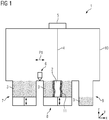
- Fig. 1 shows a schematic diagram of a device 1 according to an embodiment.
- the device 1 is used for the additive production of three-dimensional objects 2, d. H. in particular technical components or technical component groups, by successive layer-wise selective exposure and the associated successive layer-wise selective solidification of building material layers of a solidifiable building material 3, d. H. z. As a metal powder, by means of an energy or laser beam 4.
- the device 1 can be used as a laser CUSING® device, d. H. as a device for performing selective laser melting.
- the device 1 comprises the functional components required for carrying out additive construction processes; in Fig. 1 For example, a coating device 5 and an exposure device 6 are shown.
- the coating device 5 is set up in a building plane of the device 1 for the purpose of forming building material layers to be selectively exposed or selectively solidified.
- the coating device 5 comprises a coater element assembly (not shown) comprising a plurality of coater elements (not shown), which is mounted so as to be movable in the horizontal direction by guide means (not shown), as indicated by the double arrow P1.
- the exposure device 6 is set up for the selective exposure of building material layers to be solidified in the construction plane of the device 1 and comprises for this purpose a beam generating device (not shown) which is set up to generate a laser beam 4, optionally a beam deflection device (not shown) which deflects one of the beam generating means laser beam 4 is set up to be exposed area of a selectively to be solidified building material layer, and various optical elements such.
- a beam generating device (not shown) which is set up to generate a laser beam 4
- a beam deflection device (not shown) which deflects one of the beam generating means laser beam 4 is set up to be exposed area of a selectively to be solidified building material layer, and various optical elements such.
- a dosing module 7, a building module 8 and an overflow module 9 are shown, which are docked to a lower region of an intertizable process chamber 10 of the device 1.
- the mentioned modules can also form a lower region of the process chamber 10.
- a method for the additive production of three-dimensional objects 2 by successive layerwise selective exposure and concomitant successive layerwise selective solidification of building material layers of a solidifiable building material 3 can be implemented.
- the successive layerwise selective exposure or solidification of respective selectively to be consolidated building material layers is based on object-related Bau schemes.
- Corresponding Bauberries describe the geometric-constructive shape of the object to be produced in each case additively 2 and may include, for example, "geslicte" CAD data of the object 2 to be produced additively.
- the process may be a laser CUSING® process, ie a selective laser melting process.
- the method takes place in the context of the additive production of a respective additive to be produced object 2, d. H.
- a respective additive to be produced object 2 In addition to the additive structure or the additive formation of a respective object to be actually produced 2 also an additive structure or an additive training of a support structure 11.
- the support structure 11 supports the respective object 2 at least partially, thus exerting the support structure 11 at least partially to the respective Object 2 acting support effect.
- Embodiments of a support structure 11 are in the Fig. 2, 3rd shown in a schematic diagram.
- object 2 is in the Fig. 2, 3rd by way of example, a filigree cube-like framework construction consisting of individual strut-like object sections arranged or aligned along the edges of an imaginary cube is shown.
- the support structure 11 directly surrounds a respective object 2, ie individual, several or all object sections of the respective object 2.
- the object 2 (precisely fitting) is embedded in the support structure 11.
- the support structure 11 may be formed with a plurality of contiguous or multiple non-contiguous support structure sections, or may comprise a plurality of contiguous or multiple non-contiguous support structure sections. Corresponding support structure sections extend in each case at least partially surrounding each at least in sections along the respective object 2.
- the support structure 11 is formed in the context of the additive production of the respective object 2.
- the support structure 11 is according to the method by successive layerwise selective exposure and subsequent successive layerwise selective pre-solidification of Building material layers formed from the means of the energy beam 4 solidified building material 3.
- the successive layerwise selective exposure or preconsolidation of respective building material layers to be selectively consolidated is carried out on the basis of supporting structure-related building data.
- Corresponding Bau stylist describe the geometric-constructive shape of the respective additive to be produced support structure and may include, for example, "geslicte" CAD data of the additive to be produced support structure 11.
- the supporting structure-related building data can be generated on the basis of respective object-related building data. In this way, it is equally ensured that the support structure 11 is in any case formed taking into account the geometric shape of the object 2 to be supported in each case.
- a preconsolidation is to be understood as meaning a slight (re) hardening of the building material 3, in particular in comparison to the hardening of the building material 3 for the purpose of forming the object 2 which is actually to be produced.
- the pre-consolidation implemented for the formation of the support structure 11 differs from the solidification implemented for the formation of the object 2 which is actually to be produced, that is to say the degree of solidification realized in each case.
- the building material 3 is (significantly) less solidified than for the formation of the object to be actually produced 2, which z. B.
- the support structure 11 has z. As a (significantly) lower density and a (significantly) lower strength than the respective object 2.
- the successive layerwise selective solidification of the building material 3 to Training of the object 2 takes place in a first degree of consolidation of the building material 3 and the successive layerwise selective preconsolidation of the building material 3 to form the support structure 11 in a below the first degree of solidification second degree of consolidation of the building material 3.
- the second degree of solidification is chosen low, so that the support structure 11 easily, ie in particular without damaging the object 2, remove from the object 2.
- the second degree of consolidation is chosen to be so small that the support structure 11 can be manually removed from the object 2 or decays by itself during an unpacking operation of the object 2.
- the successive layerwise selective solidification of the building material 3 for the formation of the object 2 is accomplished by a complete melting (and subsequent cooling) of the building material 3.
- the successive layerwise selective solidification of the building material 3 to form the object takes place by selectively introducing radiant energy, which is the building material 3 heated to a temperature above its melting temperature, so that the building material 3 is melted.
- the building material 3 completes a phase transition.
- the successive layerwise selective pre-consolidation of the building material 3 to form the support structure 11 is not carried out by (complete) melting (and subsequent cooling) of the building material 3.
- the successive layerwise selective pre-consolidation of the building material 3 to form the support structure 11 by selective introduction of radiant energy which heats the building material 3 to a temperature below its melting temperature, which optionally allows a sintered connection of adjacent building material particles formed by a sintering neck formation.
- the building material 3 does not undergo any phase transition.
- the support structure 11 can be formed at least in sections, in particular completely, porous, ie with a certain porosity. Specifically, the support structure 11 z. B. formed as a sponge structure ("sponge support”) become.
- the support structure 11 Due to the fact that the support structure 11 directly surrounds the object 2, respectively, or the object 2 is embedded in the support structure 11, the support structure 11 can also be located in hard-to-access, e.g. B. undercut areas (if any) of the object 2 has a sufficient support effect.
- the support structure 11 can be as in FIG Fig. 2 shown formed with the object 2 (completely) surrounding geometric shape.
- the geometric shape of the support structure 2 is selected as a function of the geometric shape of the object 2 and the degree of ambience, ie the degree to which the support structure 11 is to surround the object 2.
- the support structure 11 with a cuboid or - shaped, optionally dice-shaped or, formed.
- the object 2 is arranged within the support structure 11, the support structure 11 surrounds the object 2 completely.
- each strut-like object section is surrounded directly by the support structure 11.
- a support structure 11 of a z. B. spherical or-shaped geometric shape can be achieved.
- the spherical or - shaped geometric shape of the support structure 11 would be such that it completely surrounds the object 2.
- the support structure 11 in free, d. H. In particular, not geometrically clearly defined, geometric shapes are formed.
- the support structure 11 may be formed with a contour of the contour, in particular the outer and / or inner contour of the object 2 following geometric shape.
- the contour of the object 2 following geometric shape of the support structure 11th corresponds essentially to the geometric shape of the object 2 Fig. 3
- the support structure 11 also has a geometric shape of a filigree cube-like framework construction consisting of individual (hollow) strut-like support structure sections arranged along the edges of an imaginary cube.
- the (hollow) striving-like support structure sections completely surround the respective strut-like object sections associated therewith.
- the support structure 11 is formed with a geometric shape following the contour of the object 2, the amount of building material 3 used to form the support structure 11 can be kept comparatively small.
Landscapes
- Engineering & Computer Science (AREA)
- Chemical & Material Sciences (AREA)
- Materials Engineering (AREA)
- Manufacturing & Machinery (AREA)
- Physics & Mathematics (AREA)
- Optics & Photonics (AREA)
- Mechanical Engineering (AREA)
- Plasma & Fusion (AREA)
- Powder Metallurgy (AREA)
- Producing Shaped Articles From Materials (AREA)
- Laser Beam Processing (AREA)
Abstract
Description
- Die Erfindung betrifft ein Verfahren zur additiven Herstellung eines dreidimensionalen Objekts durch sukzessive schichtweise selektive Belichtung und damit einhergehende sukzessive schichtweise selektive Verfestigung von Baumaterialschichten aus einem vermittels eines Energiestrahls verfestigbaren Baumaterial.
- Entsprechende Verfahren zur additiven Herstellung dreidimensionaler Objekte sind dem Grunde nach bekannt. Ein bekanntes Beispiel für ein entsprechendes Verfahren ist ein selektives Laserschmelzverfahren, kurz SLM-Verfahren.
- Im Rahmen der Durchführung entsprechender Verfahren ist es weiterhin bekannt, Stützstrukturen auszubilden. Entsprechende Stützstrukturen zeichnen sich durch eine Stützwirkung für jeweilige additiv herzustellende bzw. hergestellte dreidimensionale Objekte aus und umfassen typischerweise eine Vielzahl an strebenartigen bzw. -förmigen Stützelementen. Mithin werden jeweilige additiv herzustellende bzw. hergestellte dreidimensionale Objekte durch entsprechende Stützstrukturen gestützt. Entsprechende Stützstrukturen werden nach Fertigstellung des additiven Bauvorgangs typischerweise von dem jeweiligen additiv hergestellten dreidimensionalen Objekt entfernt.
- Insbesondere bei der additiven Herstellung dreidimensionaler Objekte mit filigraner bzw. komplexer geometrisch-konstruktiver Gestalt ist es bisweilen schwierig, Stützstrukturen auszubilden, welche einerseits auch in schwer zugänglichen, z. B. hinterschnittenen, Bereichen eines jeweiligen dreidimensionalen Objekts eine ausreichende Stützwirkung aufweisen und sich andererseits ohne Beschädigung des jeweiligen dreidimensionalen Objekts entfernen lassen.
- Der Erfindung liegt die Aufgabe zugrunde, ein, insbesondere im Hinblick auf die Realisierung einer demgegenüber verbesserten Stützstruktur, verbessertes Verfahren zur additiven Herstellung eines dreidimensionalen Objekts anzugeben.
- Die Aufgabe wird durch ein Verfahren zur additiven Herstellung eines dreidimensionalen Objekts gemäß Anspruch 1 gelöst. Die hierzu abhängigen Ansprüche betreffen mögliche Ausführungsformen des Verfahrens. Die Aufgabe wird ferner durch eine Vorrichtung gemäß Anspruch 10 gelöst.
- Das hierin beschriebene Verfahren dient zur additiven Herstellung dreidimensionaler Objekte, d. h. beispielsweise technischer Bauteile bzw. technischer Bauteilgruppen, durch sukzessive schichtweise selektive Belichtung und damit einhergehende sukzessive schichtweise selektive Verfestigung von Baumaterialschichten aus einem verfestigbaren Baumaterial. Bei dem Baumaterial kann es sich um ein partikuläres bzw. pulverförmiges Metall-, Kunststoff- und/oder Keramikmaterial handeln. Die sukzessive schichtweise selektive Belichtung bzw. Verfestigung jeweiliger selektiv zu verfestigender Baumaterialschichten erfolgt auf Grundlage objektbezogener Baudaten. Entsprechende Baudaten beschreiben die geometrisch-konstruktive Gestalt des jeweils additiv herzustellenden Objekts und können beispielsweise "geslicte" CAD-Daten des additiv herzustellenden Objekts beinhalten. Das Verfahren kann z. B. als selektives Laserschmelzverfahren (SLM-Verfahren) oder als selektives Lasersinterverfahren (SLS-Verfahren) implementiert sein.
- Verfahrensgemäß erfolgt im Rahmen der additiven Herstellung eines jeweiligen additiv herzustellenden dreidimensionalen Objekts - im Weiteren ist abgekürzt von "Objekt" die Rede - d. h. neben dem additiven Aufbau bzw. der additiven Ausbildung eines jeweiligen eigentlich herzustellenden Objekts auch ein additiver Aufbau bzw. eine additive Ausbildung einer Stützstruktur. Die Stützstruktur stützt ein jeweiliges Objekt zumindest abschnittsweise; die Stützstruktur übt damit eine zumindest abschnittsweise auf ein jeweiliges Objekt wirkende Stützwirkung aus.
- Die verfahrensgemäß ausgebildete Stützstruktur umgibt ein jeweiliges Objekt, d. h. einzelne, mehrere oder sämtliche Objektabschnitte des jeweiligen Objekts, unmittelbar. Mit anderen Worten ist das jeweilige Objekt zumindest abschnittsweise, insbesondere vollständig, in die Stützstruktur eingebettet. Es besteht sonach zumindest abschnittsweise, insbesondere vollständig, ein unmittelbarer mechanischer Kontakt zwischen der Stützstruktur und dem jeweiligen zu stützenden bzw. gestützten Objekt.
- Dabei ist es denkbar, dass die Stützstruktur das jeweilige Objekt zumindest abschnittsweise, z. B. mit mehreren zusammenhängenden oder mehreren nicht zusammenhängenden Stützstrukturabschnitten, umgibt oder die Stützstruktur das jeweilige Objekt, z. B. mit mehreren zusammenhängenden oder mehreren nicht zusammenhängenden Stützstrukturabschnitten, vollständig umgibt. Die Stützstruktur kann sonach mit mehreren zusammenhängenden oder mehreren nicht zusammenhängenden Stützstrukturabschnitten ausgebildet werden bzw. mehrere zusammenhängende oder mehrere nicht zusammenhängende Stützstrukturabschnitte umfassen. Entsprechende Stützstrukturabschnitte erstrecken sich dieses jeweils zumindest abschnittsweise umgebend jeweils zumindest abschnittsweise entlang des jeweiligen Objekts.
- Wie erwähnt, erfolgt die Ausbildung der Stützstruktur im Rahmen der additiven Herstellung des jeweiligen Objekts. Die Stützstruktur wird verfahrensgemäß durch sukzessive schichtweise selektive Belichtung und damit einhergehende sukzessive schichtweise selektive Vorverfestigung von Baumaterialschichten aus dem vermittels des Energiestrahls verfestigbaren Baumaterial gebildet. Die sukzessive schichtweise selektive Belichtung bzw. Vorverfestigung jeweiliger selektiv zu verfestigender Baumaterialschichten erfolgt auf Grundlage stützstrukturbezogener Baudaten. Entsprechende Baudaten beschreiben die geometrisch-konstruktive Gestalt der jeweils additiv herzustellenden Stützstruktur und können beispielsweise "geslicte" CAD-Daten der additiv herzustellenden Stützstruktur beinhalten.
- Wesentlich ist, dass die Ausbildung der Stützstruktur durch eine Vorverfestigung des Baumaterials erfolgt. Unter einer Vorverfestigung ist eine, insbesondere im Vergleich zu der Verfestigung des Baumaterials zur Ausbildung des eigentlich herzustellenden Objekts, geringfügige(re) Verfestigung des Baumaterials zu verstehen. Die zur Ausbildung der Stützstruktur implementierte Vorverfestigung unterscheidet sich von der zur Ausbildung eines jeweils eigentlich herzustellenden Objekts implementierten Verfestigung sonach in dem jeweils realisierten Verfestigungsgrad. Zur Ausbildung der Stützstruktur wird das Baumaterial (deutlich) weniger verfestigt - wie sich im Weiteren ergibt, erfolgt hier typischerweise kein vollständiges Aufschmelzen des Baumaterials - als zur Ausbildung des jeweiligen eigentlich herzustellenden Objekts, was z. B. durch den Einsatz unterschiedlicher, d. h. insbesondere unterschiedlich leistungsstarker, Belichtungseinrichtungen und/oder unterschiedlicher Belichtungsparameter, insbesondere durch eine geringere Belichtungsintensität, kürzere Belichtungszeit, etc., realisiert werden kann. Aus den unterschiedlichen Verfestigungsgraden ergeben sich auch unterschiedliche strukturelle, d. h. insbesondere mechanische, Eigenschaften zwischen der Stützstruktur und dem eigentlich hergestellten Objekt; typischerweise weist die Stützstruktur z. B. eine (deutlich) geringere Dichte und eine (deutlich) geringere Festigkeit als das jeweilige Objekt auf.
- Dadurch, dass die Stützstruktur das jeweilige Objekt (zumindest abschnittsweise) unmittelbar umgibt respektive das jeweilige Objekt (zumindest abschnittsweise) (passgenau) in die Stützstruktur eingebettet ist, weist die Stützstruktur auch in schwer zugänglichen, z. B. hinterschnittenen, Bereichen (soweit vorhanden) des jeweiligen Objekts eine ausreichende Stützwirkung auf. Dadurch, dass die Stützstruktur durch eine Vorverfestigung des Baumaterials ausgebildet wird, lässt sich diese problemlos, d. h. insbesondere ohne Beschädigung des jeweiligen Objekts, von dem jeweiligen Objekt entfernen. Insgesamt liegt damit ein verbessertes Verfahren zur additiven Herstellung dreidimensionaler Objekte vor.
- Es wurde erwähnt, dass die Vorverfestigung zur Ausbildung der Stützstruktur sich von der Verfestigung zur Ausbildung des eigentlich herzustellenden Objekts in dem jeweils realisierten Verfestigungsgrad unterscheidet. Die sukzessive schichtweise selektive Verfestigung des Baumaterials zur Ausbildung eines jeweiligen Objekts erfolgt typischerweise in einem ersten Verfestigungsgrad des Baumaterials und die sukzessive schichtweise selektive Vorverfestigung des Baumaterials zur Ausbildung der Stützstruktur in einem unterhalb des ersten Verfestigungsgrads liegenden zweiten Verfestigungsgrad des Baumaterials. Der zweite Verfestigungsgrad ist typischerweise gering gewählt, sodass sich die Stützstruktur problemlos, d. h. insbesondere ohne Beschädigung des jeweiligen Objekts, von dem jeweiligen Objekt entfernen lässt. Insbesondere kann der zweite Verfestigungsgrad so gering gewählt werden, dass die Stützstruktur sich von Hand von dem jeweiligen Objekt entfernen lässt oder während eines Auspackvorgangs des jeweiligen Objekts von selbst zerfällt.
- Konkret kann die Stützstruktur zumindest abschnittsweise, insbesondere vollständig, porös, d. h. mit einer bestimmten Porosität, ausgebildet werden. Unter einer porösen Ausbildung der Stützstruktur ist im Allgemeinen jedwede feingliedrige Struktur, welche sich aufgrund ihrer feingliedrigen Gestalt ohne Beschädigung eines jeweiligen Objekts von dem jeweiligen Objekt entfernen lässt, d. h. z. B. auch eine Schwammstruktur, zu verstehen.
- Die sukzessive schichtweise selektive Verfestigung des Baumaterials zur Ausbildung des Objekts kann insbesondere durch ein vollständiges Aufschmelzen (und nachfolgendes Abkühlen) des Baumaterials erfolgen. Die sukzessive schichtweise selektive Verfestigung des Baumaterials zur Ausbildung des Objekts erfolgt sonach typischerweise durch selektives Einbringen von Strahlungsenergie, welche das Baumaterial auf eine oberhalb seiner Schmelztemperatur liegende Temperatur erwärmt, sodass das Baumaterial aufgeschmolzen wird und einen Phasenübergang (fest-flüssig) vollzieht. Dagegen erfolgt die sukzessive schichtweise selektive Vorverfestigung des Baumaterials zur Ausbildung der Stützstruktur typischerweise nicht durch ein (vollständiges) Aufschmelzen (und nachfolgendes Abkühlen) des Baumaterials. Die sukzessive schichtweise selektive Vorverfestigung des Baumaterials zur Ausbildung der Stützstruktur erfolgt typischerweise durch selektives Einbringen von Strahlungsenergie, welche das Baumaterial auf eine unterhalb seiner Schmelztemperatur liegende Temperatur erwärmt, sodass das Baumaterial nicht aufgeschmolzen wird und somit keinen Phasenübergang (fest-flüssig) vollzieht.
- Durch die schichtweise sukzessive selektive Vorverfestigung kann gegebenenfalls eine durch eine Sinterhalsbildung zwischen benachbarten Baumaterialpartikeln gebildete Sinterverbindung benachbarter Baumaterialpartikel ausgebildet werden. Das Baumaterial vollzieht dabei jedoch keinen Phasenübergang.
- Um das herzustellende bzw. hergestellte Objekte, insbesondere vollständig, zu umgeben, kann die Stützstruktur mit einer das herzustellende bzw. hergestellte Objekt (vollständig) umgebenden geometrischen Gestalt ausgebildet werden. Die geometrische Gestalt der Stützstruktur ist insbesondere in Abhängigkeit der geometrischen Gestalt des herzustellenden bzw. hergestellten Objekts und des Umgebungsgrads, d. h. des Grads, inwieweit die Stützstruktur das Objekt umgeben soll, zu wählen. Entsprechend wird lediglich beispielhaft erwähnt, dass die Stützstruktur mit einer quaderartigen bzw. -förmigen, gegebenenfalls würfelartigen bzw. -förmigen, oder einer kugelartigen bzw. -förmigen geometrischen Gestalt ausgebildet werden kann. Selbstverständlich kann die Stützstruktur auch in freien, d. h. insbesondere nicht geometrisch eindeutig definierten, geometrischen Gestalten ausgebildet werden kann.
- So ist es z. B. möglich, dass die Stützstruktur mit einer der Kontur, insbesondere der Außen- und/oder Innenkontur, des jeweils herzustellenden bzw. hergestellten Objekts folgenden geometrischen Gestalt ausgebildet wird. Die der Kontur des Objekts folgende geometrische Gestalt der Stützstruktur entspricht sonach - abgesehen von einem gewissen Aufmaß - im Wesentlichen der geometrischen Gestalt des jeweils herzustellenden bzw. hergestellten Objekts. Dadurch, dass die Stützstruktur mit einer der Kontur des jeweils herzustellenden bzw. hergestellten Objekts folgenden geometrischen Gestalt ausgebildet wird, kann die zur Ausbildung der Stützstruktur verwendete Menge an Baumaterial vergleichsweise klein gehalten werden.
- Es wurde erwähnt, dass die sukzessive schichtweise selektive Belichtung bzw. Verfestigung jeweiliger selektiv zu verfestigender Baumaterialschichten zur Ausbildung jeweiliger Objekte auf Grundlage objektbezogener Baudaten erfolgt.
- Weiter wurde erwähnt, dass die sukzessive schichtweise selektive Belichtung bzw. Vorverfestigung jeweiliger selektiv zu verfestigender Baumaterialschichten zur Ausbildung der Stützstruktur auf Grundlage stützstrukturbezogener Baudaten erfolgt. Um den, insbesondere rechnerischen, Aufwand zur Erzeugung der stützstrukturbezogenen Baudaten gering zu halten, können die stützstrukturbezogenen Baudaten auf Grundlage jeweiliger objektbezogener Baudaten erzeugt werden. Derart ist gleichermaßen sichergestellt, dass die Stützstruktur bzw. die Stützwirkung jedenfalls unter Berücksichtigung der geometrischen Gestalt des jeweils zu stützenden Objekt(abschnitt)s ausgebildet wird.
- Die Erfindung betrifft ferner eine Vorrichtung zur additiven Herstellung dreidimensionaler Objekte durch sukzessive schichtweise selektive Belichtung und damit einhergehende sukzessive schichtweise selektive Verfestigung von Baumaterialschichten aus einem vermittels eines Energiestrahls verfestigbaren Baumaterial. Die Vorrichtung kann z. B. als SLM-Vorrichtung, d. h. als Vorrichtung zur Durchführung selektiver Laserschmelzverfahren (SLM-Verfahren), oder als SLS-Vorrichtung, d. h. als Vorrichtung zur Durchführung selektiver Lasersinterverfahren (SLS-Verfahren), ausgebildet sein. Die Vorrichtung zeichnet sich dadurch aus, dass sie zur Durchführung des beschriebenen Verfahrens eingerichtet ist. Mithin gelten sämtliche Ausführungen im Zusammenhang mit dem Verfahren analog für die Vorrichtung.
- Die Vorrichtung umfasst die zur Durchführung additiver Bauvorgänge typischerweise erforderlichen Funktionskomponenten. Hierzu zählen insbesondere eine Beschichtungseinrichtung, welche zur Ausbildung selektiv zu verfestigender Baumaterialschichten (in der Bauebene der Vorrichtung) eingerichtet ist, und eine Belichtungseinrichtung, welche zur selektiven Belichtung selektiv zu verfestigender Baumaterialschichten (in der Bauebene der Vorrichtung) eingerichtet ist. Die Beschichtungseinrichtung umfasst typischerweise mehrere Bestandteile, d. h. z. B. ein ein, insbesondere klingenförmiges, Beschichtungswerkzeug umfassendes Beschichtungselement sowie eine Führungseinrichtung zur Führung des Beschichtungselements entlang einer definierten Bewegungsbahn. Auch die Belichtungseinrichtung umfasst typischerweise mehrere Bestandteile, d. h. z. B. eine Strahlerzeugungseinrichtung zur Erzeugung eines Energie- bzw. Laserstrahls, eine Strahlablenkeinrichtung (Scannereinrichtung) zur Ablenkung eines von der Strahlerzeugungseinrichtung erzeugten Energie- bzw. Laserstrahls auf einen zu belichtenden Bereich einer selektiv zu verfestigenden Baumaterialschicht sowie diverse optische Elemente, wie z. B. Linsenelemente, Objektivelemente, etc.
- Die Erfindung ist anhand von Ausführungsbeispielen in den Zeichnungsfiguren näher erläutert. Dabei zeigt:
- Fig.1
- eine Prinzipdarstellung einer Vorrichtung gemäß einem Ausführungsbeispiel; und
- Fig. 2, 3
- je eine Prinzipdarstellung einer Stützstruktur gemäß einem Ausführungsbeispiel.
-
Fig. 1 zeigt eine Prinzipdarstellung einer Vorrichtung 1 gemäß einem Ausführungsbeispiel. - Die Vorrichtung 1 dient der additiven Herstellung dreidimensionaler Objekte 2, d. h. insbesondere technischer Bauteile bzw. technischer Bauteilgruppen, durch sukzessives schichtweises selektives Belichten und damit einhergehendes sukzessives schichtweises selektives Verfestigen von Baumaterialschichten aus einem verfestigbaren Baumaterial 3, d. h. z. B. eines Metallpulvers, vermittels eines Energie- bzw. Laserstrahls 4. Die Vorrichtung 1 kann als Laser-CUSING®-Vorrichtung, d. h. als Vorrichtung zur Durchführung selektiver Laserschmelzverfahren, ausgebildet sein.
- Die Vorrichtung 1 umfasst die zur Durchführung additiver Bauvorgänge erforderlichen Funktionskomponenten; in
Fig. 1 ist beispielsweise eine Beschichtungseinrichtung 5 und eine Belichtungseinrichtung 6 gezeigt. - Die Beschichtungseinrichtung 5 ist zur Ausbildung selektiv zu belichtender bzw. selektiv zu verfestigender Baumaterialschichten in einer Bauebene der Vorrichtung 1 eingerichtet. Die Beschichtungseinrichtung 5 umfasst eine mehrere Beschichterelemente (nicht gezeigt) umfassende Beschichterelementbaugruppe (nicht näher bezeichnet), welche über eine Führungseinrichtung (nicht gezeigt) in, wie durch den Doppelpfeil P1 angedeutet, horizontaler Richtung bewegbar gelagert ist.
- Die Belichtungseinrichtung 6 ist zur selektiven Belichtung selektiv zu verfestigender Baumaterialschichten in der Bauebene der Vorrichtung 1 eingerichtet und umfasst hierfür eine Strahlerzeugungseinrichtung (nicht gezeigt), welche zur Erzeugung eines Laserstrahls 4 eingerichtet ist, gegebenenfalls eine Strahlablenkeinrichtung (nicht gezeigt), welche zur Ablenkung eines von der Strahlerzeugungseinrichtung erzeugten Laserstrahls 4 auf einen zu belichtenden Bereich einer selektiv zu verfestigenden Baumaterialschicht eingerichtet ist, sowie diverse optische Elemente, wie z. B. Filterelemente, Objektivelemente, Linsenelemente, etc.
- In
Fig. 1 ist ferner ein Dosiermodul 7, ein Baumodul 8 und ein Überlaufmodul 9 dargestellt, welche an einen unteren Bereich einer intertisierbaren Prozesskammer 10 der Vorrichtung 1 angedockt sind. Die genannten Module können auch einen unteren Bereich der Prozesskammer 10 bilden. - Mit der Vorrichtung 1 lässt sich ein Verfahren zur additiven Herstellung dreidimensionaler Objekte 2 durch sukzessive schichtweise selektive Belichtung und damit einhergehende sukzessive schichtweise selektive Verfestigung von Baumaterialschichten aus einem verfestigbaren Baumaterial 3 implementieren. Die sukzessive schichtweise selektive Belichtung bzw. Verfestigung jeweiliger selektiv zu verfestigender Baumaterialschichten erfolgt auf Grundlage objektbezogener Baudaten. Entsprechende Baudaten beschreiben die geometrisch-konstruktive Gestalt des jeweils additiv herzustellenden Objekts 2 und können beispielsweise "geslicte" CAD-Daten des additiv herzustellenden Objekts 2 beinhalten. Bei dem Verfahren kann es sich um ein Laser-CUSING®-Verfahren, d. h. um ein selektives Laserschmelzverfahren, handeln.
- Verfahrensgemäß erfolgt im Rahmen der additiven Herstellung eines jeweiligen additiv herzustellenden Objekts 2, d. h. neben dem additiven Aufbau bzw. der additiven Ausbildung eines jeweiligen eigentlich herzustellenden Objekts 2 auch ein additiver Aufbau bzw. eine additive Ausbildung einer Stützstruktur 11. Die Stützstruktur 11 stützt das jeweilige Objekt 2 zumindest abschnittsweise, mithin übt die Stützstruktur 11 eine zumindest abschnittsweise auf das jeweilige Objekt 2 wirkende Stützwirkung aus.
- Ausführungsbeispiele einer Stützstruktur 11 sind in den
Fig. 2, 3 in einer Prinzipdarstellung dargestellt. Als Objekt 2 ist in denFig. 2, 3 beispielhaft jeweils eine filigrane würfelartige Gerüstkonstruktion, bestehend aus einzelnen entlang der Kanten eines gedachten Würfels angeordneten bzw. ausgerichteten strebenartigen Objektabschnitten, dargestellt. - Anhand der
Fig. 2, 3 ist ersichtlich, dass die Stützstruktur 11 ein jeweiliges Objekt 2, d. h. einzelne, mehrere oder sämtliche Objektabschnitte des jeweiligen Objekts 2, unmittelbar umgibt. Mit anderen Worten ist das Objekt 2 (passgenau) in die Stützstruktur 11 eingebettet. Es besteht sonach ein unmittelbarer mechanischer Kontakt zwischen der Stützstruktur 11 und dem jeweiligen zu stützenden bzw. gestützten Objekt 2. Die Stützstruktur 11 kann hierfür mit mehreren zusammenhängenden oder mehreren nicht zusammenhängenden Stützstrukturabschnitten ausgebildet werden bzw. mehrere zusammenhängende oder mehrere nicht zusammenhängende Stützstrukturabschnitte umfassen. Entsprechende Stützstrukturabschnitte erstrecken sich dieses jeweils zumindest abschnittsweise umgebend jeweils zumindest abschnittsweise entlang des jeweiligen Objekts 2. - Wie erwähnt, erfolgt die Ausbildung der Stützstruktur 11 im Rahmen der additiven Herstellung des jeweiligen Objekts 2. Die Stützstruktur 11 wird verfahrensgemäß durch sukzessive schichtweise selektive Belichtung und damit einhergehende sukzessive schichtweise selektive Vorverfestigung von Baumaterialschichten aus dem vermittels des Energiestrahls 4 verfestigbaren Baumaterial 3 gebildet. Die sukzessive schichtweise selektive Belichtung bzw. Vorverfestigung jeweiliger selektiv zu verfestigender Baumaterialschichten erfolgt auf Grundlage stützstrukturbezogener Baudaten. Entsprechende Baudaten beschreiben die geometrisch-konstruktive Gestalt der jeweils additiv herzustellenden Stützstruktur und können beispielsweise "geslicte" CAD-Daten der additiv herzustellenden Stützstruktur 11 beinhalten. Um den, insbesondere rechnerischen, Aufwand zur Erzeugung der stützstrukturbezogenen Baudaten gering zu halten, können die stützstrukturbezogenen Baudaten auf Grundlage jeweiliger objektbezogener Baudaten erzeugt werden. Derart ist gleichermaßen sichergestellt, dass die Stützstruktur 11 jedenfalls unter Berücksichtigung der geometrischen Gestalt des jeweils zu stützenden Objekts 2 ausgebildet wird.
- Wesentlich ist, dass die Ausbildung der Stützstruktur 11 durch eine Vorverfestigung des Baumaterials 3 erfolgt. Unter einer Vorverfestigung ist eine, insbesondere im Vergleich zu der Verfestigung des Baumaterials 3 zur Ausbildung des eigentlich herzustellenden Objekts 2, geringfügige(re) Verfestigung des Baumaterials 3 zu verstehen. Die zur Ausbildung der Stützstruktur 11 implementierte Vorverfestigung unterscheidet sich von der zur Ausbildung des eigentlich herzustellenden Objekts 2 implementierten Verfestigung sonach in dem jeweils realisierten Verfestigungsgrad. Zur Ausbildung der Stützstruktur 11 wird das Baumaterial 3 (deutlich) weniger verfestigt als zur Ausbildung des eigentlich herzustellenden Objekts 2, was z. B. durch den Einsatz unterschiedlicher Belichtungseinrichtungen und/oder unterschiedlicher Belichtungsparameter, insbesondere durch eine geringere Belichtungsintensität, kürzere Belichtungszeit, etc., realisiert wird. Aus den unterschiedlichen Verfestigungsgraden ergeben sich auch unterschiedliche strukturelle, d. h. insbesondere mechanische, Eigenschaften zwischen der Stützstruktur 11 und dem eigentlich hergestellten Objekt 2; die Stützstruktur 11 weist z. B. eine (deutlich) geringere Dichte und eine (deutlich) geringere Festigkeit als das jeweilige Objekt 2 auf.
- Die sukzessive schichtweise selektive Verfestigung des Baumaterials 3 zur Ausbildung des Objekts 2 erfolgt in einem ersten Verfestigungsgrad des Baumaterials 3 und die sukzessive schichtweise selektive Vorverfestigung des Baumaterials 3 zur Ausbildung der Stützstruktur 11 in einem unterhalb des ersten Verfestigungsgrads liegenden zweiten Verfestigungsgrad des Baumaterials 3. Der zweite Verfestigungsgrad ist gering gewählt, sodass sich die Stützstruktur 11 problemlos, d. h. insbesondere ohne Beschädigung des Objekts 2, von dem Objekt 2 entfernen lässt. Insbesondere wird der zweite Verfestigungsgrad so gering gewählt, dass die Stützstruktur 11 sich von Hand von dem Objekt 2 entfernen lässt oder während eines Auspackvorgangs des Objekts 2 von selbst zerfällt.
- Die sukzessive schichtweise selektive Verfestigung des Baumaterials 3 zur Ausbildung des Objekts 2 erfolgt durch ein vollständiges Aufschmelzen (und nachfolgendes Abkühlen) des Baumaterials 3. Die sukzessive schichtweise selektive Verfestigung des Baumaterials 3 zur Ausbildung des Objekts erfolgt sonach durch selektives Einbringen von Strahlungsenergie, welche das Baumaterial 3 auf eine oberhalb seiner Schmelztemperatur liegende Temperatur erwärmt, sodass das Baumaterial 3 aufgeschmolzen wird. Das Baumaterial 3 vollzieht dabei einen Phasenübergang. Dagegen erfolgt die sukzessive schichtweise selektive Vorverfestigung des Baumaterials 3 zur Ausbildung der Stützstruktur 11 nicht durch ein (vollständiges) Aufschmelzen (und nachfolgendes Abkühlen) des Baumaterials 3. Die sukzessive schichtweise selektive Vorverfestigung des Baumaterials 3 zur Ausbildung der Stützstruktur 11 erfolgt durch selektives Einbringen von Strahlungsenergie, welche das Baumaterial 3 auf eine unterhalb seiner Schmelztemperatur liegende Temperatur erwärmt, welche gegebenenfalls eine durch eine Sinterhalsbildung gebildete Sinterverbindung benachbarter Baumaterialpartikel erlaubt. Das Baumaterial 3 vollzieht dabei jedoch keinen Phasenübergang.
- Zur Realisierung entsprechend fragiler Eigenschaften der Stützstruktur 11, kann die Stützstruktur 11 zumindest abschnittsweise, insbesondere vollständig, porös, d. h. mit einer bestimmten Porosität, ausgebildet werden. Konkret kann die Stützstruktur 11 z. B. als Schwammstruktur ("Schwammsupport") ausgebildet werden.
- Dadurch, dass die Stützstruktur 11 das Objekt 2 unmittelbar umgibt respektive das Objekt 2 in die Stützstruktur 11 eingebettet ist, weist die Stützstruktur 11 auch in schwer zugänglichen, z. B. hinterschnittenen, Bereichen (soweit vorhanden) des Objekts 2 eine ausreichende Stützwirkung auf. Dadurch, dass die Stützstruktur 11 durch eine Vorverfestigung des Baumaterials 3 ausgebildet wird, lässt sich diese problemlos, d. h. insbesondere ohne Beschädigung des Objekts 2, von dem Objekt 2 entfernen.
- Um das herzustellende bzw. hergestellte Objekte 2 zu umgeben, kann die Stützstruktur 11 wie in
Fig. 2 gezeigt mit einer das Objekt 2 (vollständig) umgebenden geometrischen Gestalt ausgebildet werden. Die geometrische Gestalt der Stützstruktur 2 ist in Abhängigkeit der geometrischen Gestalt des Objekts 2 und des Umgebungsgrads, d. h. des Grads, inwieweit die Stützstruktur 11 das Objekt 2 umgeben soll, gewählt. In dem inFig. 2 gezeigten Ausführungsbeispiel ist die Stützstruktur 11 mit einer quaderartigen bzw. - förmigen, gegebenenfalls würfelartigen bzw. -förmigen, ausgebildet. Ersichtlich ist das Objekt 2 innerhalb der Stützstruktur 11 angeordnet, die Stützstruktur 11 umgibt das Objekt 2 vollständig. Insbesondere ist jeder strebenartige Objektabschnitt unmittelbar von der Stützstruktur 11 umgeben. - Das gleiche Ergebnis könnte mit einer Stützstruktur 11 einer z. B. kugelartigen bzw. -förmigen geometrischen Gestalt erreicht werden. Die kugelartige bzw. - förmige geometrische Gestalt der Stützstruktur 11 wäre so bemessen, dass diese das Objekt 2 vollständig umgibt. Grundsätzlich kann die Stützstruktur 11 auch in freien, d. h. insbesondere nicht geometrisch eindeutig definierten, geometrischen Gestalten ausgebildet werden.
- In dem in
Fig. 3 gezeigten Ausführungsbeispiel ist gezeigt, dass die Stützstruktur 11 auch mit einer der Kontur, insbesondere der Außen- und/oder Innenkontur, des Objekts 2 folgenden geometrischen Gestalt ausgebildet sein kann. Die der Kontur des Objekts 2 folgende geometrische Gestalt der Stützstruktur 11 entspricht sonach - abgesehen von einem gewissen Aufmaß - im Wesentlichen der geometrischen Gestalt des Objekts 2. In dem inFig. 3 gezeigten Ausführungsbeispiel weist die Stützstruktur 11 ebenso eine geometrische Gestalt einer filigranen würfelartigen Gerüstkonstruktion, bestehend aus einzelnen entlang der Kanten eines gedachten Würfels angeordneten bzw. ausgerichteten (hohl)strebenartigen Stützstrukturabschnitten, auf. Die (hohl)strebenartigen Stützstrukturabschnitte umgeben die diesen jeweils zugeordneten strebenartigen Objektabschnitte vollständig. - Dadurch, dass die Stützstruktur 11 mit einer der Kontur des Objekts 2 folgenden geometrischen Gestalt ausgebildet wird, kann die zur Ausbildung der Stützstruktur 11 verwendete Menge an Baumaterial 3 vergleichsweise klein gehalten werden.
Claims (10)
- Verfahren zur additiven Herstellung eines dreidimensionalen Objekts (2) durch sukzessive schichtweise selektive Belichtung und damit einhergehende sukzessive schichtweise selektive Verfestigung von Baumaterialschichten aus einem vermittels eines Energiestrahls (4) verfestigbaren Baumaterial (3), dadurch gekennzeichnet, dass im Rahmen der additiven Herstellung des additiv herzustellenden dreidimensionalen Objekts (2) eine das additiv herzustellende oder hergestellte dreidimensionale Objekt (2) unmittelbar umgebende Stützstruktur (11) durch sukzessive schichtweise selektive Belichtung und damit einhergehende sukzessive schichtweise selektive Vorverfestigung von Baumaterialschichten aus dem vermittels des Energiestrahls (4) verfestigbaren Baumaterial (3) gebildet wird.
- Verfahren nach Anspruch 1, dadurch gekennzeichnet, dass die sukzessive schichtweise selektive Verfestigung des Baumaterials (3) zur Ausbildung des dreidimensionalen Objekts (2) in einem ersten Verfestigungsgrad des Baumaterials (3) erfolgt und die sukzessive schichtweise selektive Vorverfestigung des Baumaterials (3) zur Ausbildung der Stützstruktur (11) in einem unterhalb des ersten Verfestigungsgrads liegenden zweiten Verfestigungsgrad des Baumaterials (3) erfolgt.
- Verfahren nach Anspruch 2, dadurch gekennzeichnet, dass der zweite Verfestigungsgrad des Baumaterials (3) gering gewählt wird, sodass die Stützstruktur (11) während eines Auspackvorgangs des additiv hergestellten dreidimensionalen Objekts (2) von selbst zerfällt oder sich von Hand entfernen lässt.
- Verfahren nach einem der vorhergehenden Ansprüche, dadurch gekennzeichnet, dass die Stützstruktur (11) zumindest abschnittsweise porös ausgebildet wird.
- Verfahren nach einem der vorhergehenden Ansprüche, dadurch gekennzeichnet, dass die sukzessive schichtweise selektive Verfestigung des Baumaterials (3) zur Ausbildung des dreidimensionalen Objekts (2) durch ein vollständiges Aufschmelzen und nachfolgendes Abkühlen des Baumaterials (3) erfolgt und die sukzessive schichtweise selektive Vorverfestigung des Baumaterials (3) zur Ausbildung der Stützstruktur nicht durch ein vollständiges Aufschmelzen und nachfolgendes Abkühlen des Baumaterials (3) erfolgt.
- Verfahren nach einem der vorhergehen Ansprüche, dadurch gekennzeichnet, dass die Stützstruktur (11) mit mehreren zusammenhängenden oder mehreren nicht zusammenhängenden Stützstrukturabschnitten ausgebildet wird.
- Verfahren nach einem der vorhergehenden Ansprüche, dadurch gekennzeichnet, dass die Stützstruktur (11) mit einer das additiv herzustellende oder hergestellte dreidimensionale Objekt (2) umgebenden quaderförmigen geometrischen Gestalt ausgebildet wird oder die Stützstruktur (11) mit einer der Kontur, insbesondere der Außen- und/oder Innenkontur, des additiv herzustellenden oder hergestellten dreidimensionalen Objekts (2) folgenden geometrischen Gestalt ausgebildet wird.
- Verfahren nach einem der vorhergehenden Ansprüche, dadurch gekennzeichnet, dass die Stützstruktur (11) das additiv herzustellende oder hergestellte dreidimensionale Objekt (2) zumindest abschnittsweise oder vollständig umgebend ausgebildet wird.
- Verfahren nach einem der vorhergehenden Ansprüche, dadurch gekennzeichnet, dass die sukzessive schichtweise selektive Belichtung und die damit einhergehende sukzessive schichtweise selektive Vorverfestigung von Baumaterialschichten aus dem vermittels des Energiestrahls verfestigbaren Baumaterial (3) auf Grundlage stützstrukturbezogener Baudaten erfolgt, wobei die stützstrukturbezogenen Baudaten auf Grundlage objektbezogener Baudaten erzeugt werden.
- Vorrichtung (1) zur additiven Herstellung dreidimensionaler Objekte (2) durch sukzessive schichtweise selektive Belichtung und damit einhergehende sukzessive schichtweise selektive Verfestigung von Baumaterialschichten aus einem vermittels eines Energiestrahls (4) verfestigbaren Baumaterial (3), dadurch gekennzeichnet, dass sie zur Durchführung des Verfahrens nach einem der vorhergehenden Ansprüche eingerichtet ist.
Applications Claiming Priority (1)
| Application Number | Priority Date | Filing Date | Title |
|---|---|---|---|
| DE102016124401.5A DE102016124401A1 (de) | 2016-12-14 | 2016-12-14 | Verfahren zur additiven Herstellung eines dreidimensionalen Objekts |
Publications (2)
| Publication Number | Publication Date |
|---|---|
| EP3335858A1 true EP3335858A1 (de) | 2018-06-20 |
| EP3335858B1 EP3335858B1 (de) | 2025-05-21 |
Family
ID=59269883
Family Applications (1)
| Application Number | Title | Priority Date | Filing Date |
|---|---|---|---|
| EP17178987.8A Active EP3335858B1 (de) | 2016-12-14 | 2017-06-30 | Verfahren zur additiven herstellung eines dreidimensionalen objekts |
Country Status (5)
| Country | Link |
|---|---|
| US (1) | US11440265B2 (de) |
| EP (1) | EP3335858B1 (de) |
| JP (3) | JP7020617B2 (de) |
| CN (1) | CN108215175A (de) |
| DE (1) | DE102016124401A1 (de) |
Families Citing this family (5)
| Publication number | Priority date | Publication date | Assignee | Title |
|---|---|---|---|---|
| JP6349561B1 (ja) * | 2017-07-31 | 2018-07-04 | 福井県 | 三次元造形方法 |
| EP3663074B1 (de) * | 2018-12-03 | 2023-03-15 | Ivoclar Vivadent AG | Verfahren zur additiven fertigung von formkörpern |
| WO2020219027A1 (en) | 2019-04-23 | 2020-10-29 | Hewlett-Packard Development Company, L.P. | Sacrificial barriers |
| DE102019116503A1 (de) * | 2019-06-18 | 2020-12-24 | SLM Solutions Group AG | Verfahren und Vorrichtung zur Herstellung eines Multimaterialwerkstücks |
| CN118180411B (zh) * | 2024-05-16 | 2024-08-23 | 临沂大学 | 一种基于数据分析的智能增材制造流程控制方法及系统 |
Citations (2)
| Publication number | Priority date | Publication date | Assignee | Title |
|---|---|---|---|---|
| DE19538257A1 (de) * | 1994-10-13 | 1996-04-18 | Eos Electro Optical Syst | Verfahren zum Herstellen eines dreidimensionalen Objektes |
| FR2974316A1 (fr) * | 2011-04-19 | 2012-10-26 | Phenix Systems | Procede de fabrication d'un objet par solidification d'une poudre a l'aide d'un laser |
Family Cites Families (8)
| Publication number | Priority date | Publication date | Assignee | Title |
|---|---|---|---|---|
| DE10042132B4 (de) * | 2000-08-28 | 2012-12-13 | Cl Schutzrechtsverwaltungs Gmbh | Selektives Randschichtschmelzen |
| DE10058748C1 (de) | 2000-11-27 | 2002-07-25 | Markus Dirscherl | Verfahren zur Herstellung eines Bauteils sowie Vorrichtung zur Durchführung des Verfahrens |
| JP2004004018A (ja) | 2002-03-29 | 2004-01-08 | Toto Ltd | 生活管理装置、生活習慣ガイド方法および健康管理システム |
| DE102007033434A1 (de) * | 2007-07-18 | 2009-01-22 | Voxeljet Technology Gmbh | Verfahren zum Herstellen dreidimensionaler Bauteile |
| WO2011085190A1 (en) | 2010-01-07 | 2011-07-14 | Corning Incorporated | Impact-damage-resistant glass sheet |
| GB201316670D0 (en) * | 2013-09-19 | 2013-11-06 | 3T Rpd Ltd | manufacturing method |
| WO2015141032A1 (ja) | 2014-03-18 | 2015-09-24 | 株式会社 東芝 | 積層造形装置及び積層造形物の製造方法 |
| JP2016198958A (ja) | 2015-04-10 | 2016-12-01 | キヤノン株式会社 | 情報処理方法、情報処理装置、立体造形方法、立体造形装置及びプログラム |
-
2016
- 2016-12-14 DE DE102016124401.5A patent/DE102016124401A1/de active Pending
-
2017
- 2017-06-30 EP EP17178987.8A patent/EP3335858B1/de active Active
- 2017-08-02 CN CN201710651141.3A patent/CN108215175A/zh active Pending
- 2017-10-27 JP JP2017207798A patent/JP7020617B2/ja active Active
- 2017-12-13 US US15/840,173 patent/US11440265B2/en active Active
-
2019
- 2019-10-17 JP JP2019189866A patent/JP2020073714A/ja active Pending
-
2021
- 2021-12-22 JP JP2021208024A patent/JP7276914B2/ja active Active
Patent Citations (2)
| Publication number | Priority date | Publication date | Assignee | Title |
|---|---|---|---|---|
| DE19538257A1 (de) * | 1994-10-13 | 1996-04-18 | Eos Electro Optical Syst | Verfahren zum Herstellen eines dreidimensionalen Objektes |
| FR2974316A1 (fr) * | 2011-04-19 | 2012-10-26 | Phenix Systems | Procede de fabrication d'un objet par solidification d'une poudre a l'aide d'un laser |
Also Published As
| Publication number | Publication date |
|---|---|
| JP7276914B2 (ja) | 2023-05-18 |
| US20180162059A1 (en) | 2018-06-14 |
| JP7020617B2 (ja) | 2022-02-16 |
| CN108215175A (zh) | 2018-06-29 |
| JP2022046610A (ja) | 2022-03-23 |
| JP2018095955A (ja) | 2018-06-21 |
| US11440265B2 (en) | 2022-09-13 |
| JP2020073714A (ja) | 2020-05-14 |
| DE102016124401A1 (de) | 2018-06-14 |
| EP3335858B1 (de) | 2025-05-21 |
Similar Documents
| Publication | Publication Date | Title |
|---|---|---|
| EP3022008B1 (de) | Verfahren zur herstellung eines bauteils sowie optische bestrahlungsvorrichtung | |
| EP3183083B2 (de) | Verfahren zum herstellen eines dreidimensionalen objekts | |
| EP1993812B1 (de) | Verfahren und vorrichtung zum herstellen eines dreidimensionalen objekts | |
| EP3335858B1 (de) | Verfahren zur additiven herstellung eines dreidimensionalen objekts | |
| EP2983895B1 (de) | Pulveraufbereitungsverfahren | |
| EP3909750B1 (de) | Verfahren zur additiven herstellung dreidimensionaler objekte | |
| DE102016209933A1 (de) | Vorrichtung und Verfahren zum generativen Herstellen eines dreidimensionalen Objekts | |
| WO2009046696A2 (de) | Materialsystem und verfahren zum verändern von eigenschaften eines kunststoffbauteiles | |
| EP3321011B1 (de) | Verfahren zur verbesserung der oberflächenqualität generativ hergestellter bauteile | |
| EP3248719B1 (de) | Verfahren und vorrichtung zum additiven herstellen zumindest eines bauteilbereichs eines bauteils | |
| DE102015001480A1 (de) | Verfahren zum Herstellen eines dreidimensionalen Objekts durch aufeinander folgendes Verfestigen von Schichten | |
| EP3455014B1 (de) | Vorrichtung mit schleuse für die additive herstellung | |
| WO2017153187A1 (de) | Generatives schichtbauverfahren mit verbesserter detailauflösung und vorrichtung zur durchführung desselben | |
| EP2851145A1 (de) | Vorrichtung zum schichtweisen Generieren von Bauteilen durch ein generatives Fertigungsverfahren, ein Verfahren sowie ein Bauteil | |
| DE102017201084A1 (de) | Verfahren zur additiven Herstellung und Beschichtungsvorrichtung | |
| DE102015217469A1 (de) | Verfahren und Vorrichtung zum Herstellen eines dreidimensionalen Objekts | |
| EP3466650A1 (de) | Vorrichtung zur additiven herstellung dreidimensionaler objekte | |
| WO2019025135A1 (de) | Verfahren zum ausbilden einer definierten oberflächenrauheit in einen bereich eines additiv herzustellenden oder hergestellten bauteils für einer strömungsmaschine | |
| EP3345745B1 (de) | Fertigungsanlage und verfahren zur herstellung eines bauteils | |
| DE102023000212A1 (de) | Verfahren und Vorrichtung zur Herstellung von Mikrobauteilen und Mikrokomponenten durch additive Fertigung mittels Mikro Laser Sintern | |
| EP3369497A1 (de) | Vorrichtung zur additiven herstellung dreidimensionaler objekte | |
| WO2017194275A1 (de) | Bauplattform für die additive herstellung und verfahren | |
| EP3986645A1 (de) | Verfahren und vorrichtung zur herstellung eines multimaterialwerkstücks | |
| WO2019120348A1 (de) | Verfahren und vorrichtung zur reinigung teilweise hergestellter bauteile während der generativen herstellung | |
| DE102014104596A1 (de) | Aufbau einer Diffusionsbarriere in einem schlickerbasierten additiven Fertigungsprozess zur Herstellung eines keramischen Grünkörpers |
Legal Events
| Date | Code | Title | Description |
|---|---|---|---|
| PUAI | Public reference made under article 153(3) epc to a published international application that has entered the european phase |
Free format text: ORIGINAL CODE: 0009012 |
|
| STAA | Information on the status of an ep patent application or granted ep patent |
Free format text: STATUS: THE APPLICATION HAS BEEN PUBLISHED |
|
| AK | Designated contracting states |
Kind code of ref document: A1 Designated state(s): AL AT BE BG CH CY CZ DE DK EE ES FI FR GB GR HR HU IE IS IT LI LT LU LV MC MK MT NL NO PL PT RO RS SE SI SK SM TR |
|
| AX | Request for extension of the european patent |
Extension state: BA ME |
|
| STAA | Information on the status of an ep patent application or granted ep patent |
Free format text: STATUS: REQUEST FOR EXAMINATION WAS MADE |
|
| 17P | Request for examination filed |
Effective date: 20181217 |
|
| RBV | Designated contracting states (corrected) |
Designated state(s): AL AT BE BG CH CY CZ DE DK EE ES FI FR GB GR HR HU IE IS IT LI LT LU LV MC MK MT NL NO PL PT RO RS SE SI SK SM TR |
|
| STAA | Information on the status of an ep patent application or granted ep patent |
Free format text: STATUS: EXAMINATION IS IN PROGRESS |
|
| 17Q | First examination report despatched |
Effective date: 20190820 |
|
| RIC1 | Information provided on ipc code assigned before grant |
Ipc: B29C 64/40 20170101AFI20210317BHEP Ipc: B22F 10/20 20210101ALI20210317BHEP Ipc: B22F 12/00 20210101ALI20210317BHEP |
|
| RAP1 | Party data changed (applicant data changed or rights of an application transferred) |
Owner name: CONCEPT LASER GMBH |
|
| REG | Reference to a national code |
Ref legal event code: R079 Free format text: PREVIOUS MAIN CLASS: B29C0064400000 Ipc: B22F0010280000 Ref country code: DE Ref document number: 502017016860 Country of ref document: DE |
|
| GRAP | Despatch of communication of intention to grant a patent |
Free format text: ORIGINAL CODE: EPIDOSNIGR1 |
|
| STAA | Information on the status of an ep patent application or granted ep patent |
Free format text: STATUS: GRANT OF PATENT IS INTENDED |
|
| RIC1 | Information provided on ipc code assigned before grant |
Ipc: B33Y 70/00 20150101ALN20241206BHEP Ipc: B22F 12/67 20210101ALN20241206BHEP Ipc: B22F 12/49 20210101ALN20241206BHEP Ipc: B29C 64/40 20170101ALI20241206BHEP Ipc: B22F 10/47 20210101ALI20241206BHEP Ipc: B22F 10/43 20210101ALI20241206BHEP Ipc: B22F 10/28 20210101AFI20241206BHEP |
|
| INTG | Intention to grant announced |
Effective date: 20250102 |
|
| GRAS | Grant fee paid |
Free format text: ORIGINAL CODE: EPIDOSNIGR3 |
|
| GRAA | (expected) grant |
Free format text: ORIGINAL CODE: 0009210 |
|
| STAA | Information on the status of an ep patent application or granted ep patent |
Free format text: STATUS: THE PATENT HAS BEEN GRANTED |
|
| AK | Designated contracting states |
Kind code of ref document: B1 Designated state(s): AL AT BE BG CH CY CZ DE DK EE ES FI FR GB GR HR HU IE IS IT LI LT LU LV MC MK MT NL NO PL PT RO RS SE SI SK SM TR |
|
| P01 | Opt-out of the competence of the unified patent court (upc) registered |
Free format text: CASE NUMBER: APP_18100/2025 Effective date: 20250414 |
|
| REG | Reference to a national code |
Ref country code: GB Ref legal event code: FG4D Free format text: NOT ENGLISH |
|
| REG | Reference to a national code |
Ref country code: CH Ref legal event code: EP |
|
| REG | Reference to a national code |
Ref country code: DE Ref legal event code: R096 Ref document number: 502017016860 Country of ref document: DE |
|
| REG | Reference to a national code |
Ref country code: IE Ref legal event code: FG4D Free format text: LANGUAGE OF EP DOCUMENT: GERMAN |
|
| REG | Reference to a national code |
Ref country code: NL Ref legal event code: MP Effective date: 20250521 |
|
| PG25 | Lapsed in a contracting state [announced via postgrant information from national office to epo] |
Ref country code: PT Free format text: LAPSE BECAUSE OF FAILURE TO SUBMIT A TRANSLATION OF THE DESCRIPTION OR TO PAY THE FEE WITHIN THE PRESCRIBED TIME-LIMIT Effective date: 20250922 Ref country code: FI Free format text: LAPSE BECAUSE OF FAILURE TO SUBMIT A TRANSLATION OF THE DESCRIPTION OR TO PAY THE FEE WITHIN THE PRESCRIBED TIME-LIMIT Effective date: 20250521 Ref country code: ES Free format text: LAPSE BECAUSE OF FAILURE TO SUBMIT A TRANSLATION OF THE DESCRIPTION OR TO PAY THE FEE WITHIN THE PRESCRIBED TIME-LIMIT Effective date: 20250521 |
|
| REG | Reference to a national code |
Ref country code: LT Ref legal event code: MG9D |
|
| PG25 | Lapsed in a contracting state [announced via postgrant information from national office to epo] |
Ref country code: NO Free format text: LAPSE BECAUSE OF FAILURE TO SUBMIT A TRANSLATION OF THE DESCRIPTION OR TO PAY THE FEE WITHIN THE PRESCRIBED TIME-LIMIT Effective date: 20250821 Ref country code: GR Free format text: LAPSE BECAUSE OF FAILURE TO SUBMIT A TRANSLATION OF THE DESCRIPTION OR TO PAY THE FEE WITHIN THE PRESCRIBED TIME-LIMIT Effective date: 20250822 |
|
| PG25 | Lapsed in a contracting state [announced via postgrant information from national office to epo] |
Ref country code: PL Free format text: LAPSE BECAUSE OF FAILURE TO SUBMIT A TRANSLATION OF THE DESCRIPTION OR TO PAY THE FEE WITHIN THE PRESCRIBED TIME-LIMIT Effective date: 20250521 Ref country code: NL Free format text: LAPSE BECAUSE OF FAILURE TO SUBMIT A TRANSLATION OF THE DESCRIPTION OR TO PAY THE FEE WITHIN THE PRESCRIBED TIME-LIMIT Effective date: 20250521 |
|
| PG25 | Lapsed in a contracting state [announced via postgrant information from national office to epo] |
Ref country code: BG Free format text: LAPSE BECAUSE OF FAILURE TO SUBMIT A TRANSLATION OF THE DESCRIPTION OR TO PAY THE FEE WITHIN THE PRESCRIBED TIME-LIMIT Effective date: 20250521 |
|
| PG25 | Lapsed in a contracting state [announced via postgrant information from national office to epo] |
Ref country code: HR Free format text: LAPSE BECAUSE OF FAILURE TO SUBMIT A TRANSLATION OF THE DESCRIPTION OR TO PAY THE FEE WITHIN THE PRESCRIBED TIME-LIMIT Effective date: 20250521 |
|
| PG25 | Lapsed in a contracting state [announced via postgrant information from national office to epo] |
Ref country code: RS Free format text: LAPSE BECAUSE OF FAILURE TO SUBMIT A TRANSLATION OF THE DESCRIPTION OR TO PAY THE FEE WITHIN THE PRESCRIBED TIME-LIMIT Effective date: 20250821 |
|
| PG25 | Lapsed in a contracting state [announced via postgrant information from national office to epo] |
Ref country code: IS Free format text: LAPSE BECAUSE OF FAILURE TO SUBMIT A TRANSLATION OF THE DESCRIPTION OR TO PAY THE FEE WITHIN THE PRESCRIBED TIME-LIMIT Effective date: 20250921 |
|
| PG25 | Lapsed in a contracting state [announced via postgrant information from national office to epo] |
Ref country code: LV Free format text: LAPSE BECAUSE OF FAILURE TO SUBMIT A TRANSLATION OF THE DESCRIPTION OR TO PAY THE FEE WITHIN THE PRESCRIBED TIME-LIMIT Effective date: 20250521 |
|
| PG25 | Lapsed in a contracting state [announced via postgrant information from national office to epo] |
Ref country code: DK Free format text: LAPSE BECAUSE OF FAILURE TO SUBMIT A TRANSLATION OF THE DESCRIPTION OR TO PAY THE FEE WITHIN THE PRESCRIBED TIME-LIMIT Effective date: 20250521 Ref country code: SM Free format text: LAPSE BECAUSE OF FAILURE TO SUBMIT A TRANSLATION OF THE DESCRIPTION OR TO PAY THE FEE WITHIN THE PRESCRIBED TIME-LIMIT Effective date: 20250521 |
|
| PG25 | Lapsed in a contracting state [announced via postgrant information from national office to epo] |
Ref country code: CZ Free format text: LAPSE BECAUSE OF FAILURE TO SUBMIT A TRANSLATION OF THE DESCRIPTION OR TO PAY THE FEE WITHIN THE PRESCRIBED TIME-LIMIT Effective date: 20250521 |
|
| PG25 | Lapsed in a contracting state [announced via postgrant information from national office to epo] |
Ref country code: EE Free format text: LAPSE BECAUSE OF FAILURE TO SUBMIT A TRANSLATION OF THE DESCRIPTION OR TO PAY THE FEE WITHIN THE PRESCRIBED TIME-LIMIT Effective date: 20250521 |
|
| PG25 | Lapsed in a contracting state [announced via postgrant information from national office to epo] |
Ref country code: SK Free format text: LAPSE BECAUSE OF FAILURE TO SUBMIT A TRANSLATION OF THE DESCRIPTION OR TO PAY THE FEE WITHIN THE PRESCRIBED TIME-LIMIT Effective date: 20250521 Ref country code: RO Free format text: LAPSE BECAUSE OF FAILURE TO SUBMIT A TRANSLATION OF THE DESCRIPTION OR TO PAY THE FEE WITHIN THE PRESCRIBED TIME-LIMIT Effective date: 20250521 |
|
| REG | Reference to a national code |
Ref country code: CH Ref legal event code: H13 Free format text: ST27 STATUS EVENT CODE: U-0-0-H10-H13 (AS PROVIDED BY THE NATIONAL OFFICE) Effective date: 20260127 |
|
| PG25 | Lapsed in a contracting state [announced via postgrant information from national office to epo] |
Ref country code: IT Free format text: LAPSE BECAUSE OF FAILURE TO SUBMIT A TRANSLATION OF THE DESCRIPTION OR TO PAY THE FEE WITHIN THE PRESCRIBED TIME-LIMIT Effective date: 20250521 |
|
| PG25 | Lapsed in a contracting state [announced via postgrant information from national office to epo] |
Ref country code: LU Free format text: LAPSE BECAUSE OF NON-PAYMENT OF DUE FEES Effective date: 20250630 |
|
| PG25 | Lapsed in a contracting state [announced via postgrant information from national office to epo] |
Ref country code: MC Free format text: LAPSE BECAUSE OF FAILURE TO SUBMIT A TRANSLATION OF THE DESCRIPTION OR TO PAY THE FEE WITHIN THE PRESCRIBED TIME-LIMIT Effective date: 20250521 |
|
| REG | Reference to a national code |
Ref country code: DE Ref legal event code: R097 Ref document number: 502017016860 Country of ref document: DE |
|
| REG | Reference to a national code |
Ref country code: BE Ref legal event code: MM Effective date: 20250630 |
|
| PLBE | No opposition filed within time limit |
Free format text: ORIGINAL CODE: 0009261 |
|
| STAA | Information on the status of an ep patent application or granted ep patent |
Free format text: STATUS: NO OPPOSITION FILED WITHIN TIME LIMIT |
|
| REG | Reference to a national code |
Ref country code: CH Ref legal event code: L10 Free format text: ST27 STATUS EVENT CODE: U-0-0-L10-L00 (AS PROVIDED BY THE NATIONAL OFFICE) Effective date: 20260402 |
|
| PG25 | Lapsed in a contracting state [announced via postgrant information from national office to epo] |
Ref country code: IE Free format text: LAPSE BECAUSE OF NON-PAYMENT OF DUE FEES Effective date: 20250630 |
|
| PG25 | Lapsed in a contracting state [announced via postgrant information from national office to epo] |
Ref country code: BE Free format text: LAPSE BECAUSE OF NON-PAYMENT OF DUE FEES Effective date: 20250630 |
|
| PG25 | Lapsed in a contracting state [announced via postgrant information from national office to epo] |
Ref country code: FR Free format text: LAPSE BECAUSE OF NON-PAYMENT OF DUE FEES Effective date: 20250721 |
|
| REG | Reference to a national code |
Ref country code: DE Ref legal event code: R082 Ref document number: 502017016860 Country of ref document: DE Representative=s name: HAFNER & KOHL PARTMBB, DE |
|
| PG25 | Lapsed in a contracting state [announced via postgrant information from national office to epo] |
Ref country code: CH Free format text: LAPSE BECAUSE OF NON-PAYMENT OF DUE FEES Effective date: 20250630 |
|
| 26N | No opposition filed |
Effective date: 20260224 |
|
| GBPC | Gb: european patent ceased through non-payment of renewal fee |
Effective date: 20250821 |
|
| PG25 | Lapsed in a contracting state [announced via postgrant information from national office to epo] |
Ref country code: LT Free format text: LAPSE BECAUSE OF FAILURE TO SUBMIT A TRANSLATION OF THE DESCRIPTION OR TO PAY THE FEE WITHIN THE PRESCRIBED TIME-LIMIT Effective date: 20250521 |
|
| PG25 | Lapsed in a contracting state [announced via postgrant information from national office to epo] |
Ref country code: GB Free format text: LAPSE BECAUSE OF NON-PAYMENT OF DUE FEES Effective date: 20250821 |
|
| PGFP | Annual fee paid to national office [announced via postgrant information from national office to epo] |
Ref country code: DE Payment date: 20260520 Year of fee payment: 10 |
|
| PG25 | Lapsed in a contracting state [announced via postgrant information from national office to epo] |
Ref country code: AT Free format text: LAPSE BECAUSE OF NON-PAYMENT OF DUE FEES Effective date: 20250630 Ref country code: SE Free format text: LAPSE BECAUSE OF FAILURE TO SUBMIT A TRANSLATION OF THE DESCRIPTION OR TO PAY THE FEE WITHIN THE PRESCRIBED TIME-LIMIT Effective date: 20250521 Ref country code: CY Free format text: LAPSE BECAUSE OF FAILURE TO SUBMIT A TRANSLATION OF THE DESCRIPTION OR TO PAY THE FEE WITHIN THE PRESCRIBED TIME-LIMIT Effective date: 20250521 |