EP3335784B1 - Fliessbett für katalytische reformierung - Google Patents
Fliessbett für katalytische reformierung Download PDFInfo
- Publication number
- EP3335784B1 EP3335784B1 EP17206290.3A EP17206290A EP3335784B1 EP 3335784 B1 EP3335784 B1 EP 3335784B1 EP 17206290 A EP17206290 A EP 17206290A EP 3335784 B1 EP3335784 B1 EP 3335784B1
- Authority
- EP
- European Patent Office
- Prior art keywords
- catalyst
- basket
- reactor
- circulation
- reactor according
- Prior art date
- Legal status (The legal status is an assumption and is not a legal conclusion. Google has not performed a legal analysis and makes no representation as to the accuracy of the status listed.)
- Active
Links
Images

Classifications
-
- B—PERFORMING OPERATIONS; TRANSPORTING
- B01—PHYSICAL OR CHEMICAL PROCESSES OR APPARATUS IN GENERAL
- B01J—CHEMICAL OR PHYSICAL PROCESSES, e.g. CATALYSIS OR COLLOID CHEMISTRY; THEIR RELEVANT APPARATUS
- B01J19/00—Chemical, physical or physico-chemical processes in general; Their relevant apparatus
- B01J19/0053—Details of the reactor
- B01J19/006—Baffles
-
- B—PERFORMING OPERATIONS; TRANSPORTING
- B01—PHYSICAL OR CHEMICAL PROCESSES OR APPARATUS IN GENERAL
- B01J—CHEMICAL OR PHYSICAL PROCESSES, e.g. CATALYSIS OR COLLOID CHEMISTRY; THEIR RELEVANT APPARATUS
- B01J8/00—Chemical or physical processes in general, conducted in the presence of fluids and solid particles; Apparatus for such processes
- B01J8/08—Chemical or physical processes in general, conducted in the presence of fluids and solid particles; Apparatus for such processes with moving particles
-
- B—PERFORMING OPERATIONS; TRANSPORTING
- B01—PHYSICAL OR CHEMICAL PROCESSES OR APPARATUS IN GENERAL
- B01J—CHEMICAL OR PHYSICAL PROCESSES, e.g. CATALYSIS OR COLLOID CHEMISTRY; THEIR RELEVANT APPARATUS
- B01J8/00—Chemical or physical processes in general, conducted in the presence of fluids and solid particles; Apparatus for such processes
- B01J8/08—Chemical or physical processes in general, conducted in the presence of fluids and solid particles; Apparatus for such processes with moving particles
- B01J8/12—Chemical or physical processes in general, conducted in the presence of fluids and solid particles; Apparatus for such processes with moving particles moved by gravity in a downward flow
-
- B—PERFORMING OPERATIONS; TRANSPORTING
- B01—PHYSICAL OR CHEMICAL PROCESSES OR APPARATUS IN GENERAL
- B01J—CHEMICAL OR PHYSICAL PROCESSES, e.g. CATALYSIS OR COLLOID CHEMISTRY; THEIR RELEVANT APPARATUS
- B01J19/00—Chemical, physical or physico-chemical processes in general; Their relevant apparatus
-
- B—PERFORMING OPERATIONS; TRANSPORTING
- B01—PHYSICAL OR CHEMICAL PROCESSES OR APPARATUS IN GENERAL
- B01J—CHEMICAL OR PHYSICAL PROCESSES, e.g. CATALYSIS OR COLLOID CHEMISTRY; THEIR RELEVANT APPARATUS
- B01J8/00—Chemical or physical processes in general, conducted in the presence of fluids and solid particles; Apparatus for such processes
- B01J8/18—Chemical or physical processes in general, conducted in the presence of fluids and solid particles; Apparatus for such processes with fluidised particles
-
- B—PERFORMING OPERATIONS; TRANSPORTING
- B01—PHYSICAL OR CHEMICAL PROCESSES OR APPARATUS IN GENERAL
- B01J—CHEMICAL OR PHYSICAL PROCESSES, e.g. CATALYSIS OR COLLOID CHEMISTRY; THEIR RELEVANT APPARATUS
- B01J8/00—Chemical or physical processes in general, conducted in the presence of fluids and solid particles; Apparatus for such processes
- B01J8/18—Chemical or physical processes in general, conducted in the presence of fluids and solid particles; Apparatus for such processes with fluidised particles
- B01J8/20—Chemical or physical processes in general, conducted in the presence of fluids and solid particles; Apparatus for such processes with fluidised particles with liquid as a fluidising medium
- B01J8/22—Chemical or physical processes in general, conducted in the presence of fluids and solid particles; Apparatus for such processes with fluidised particles with liquid as a fluidising medium gas being introduced into the liquid
- B01J8/222—Chemical or physical processes in general, conducted in the presence of fluids and solid particles; Apparatus for such processes with fluidised particles with liquid as a fluidising medium gas being introduced into the liquid in the presence of a rotating device only
-
- C—CHEMISTRY; METALLURGY
- C10—PETROLEUM, GAS OR COKE INDUSTRIES; TECHNICAL GASES CONTAINING CARBON MONOXIDE; FUELS; LUBRICANTS; PEAT
- C10G—CRACKING HYDROCARBON OILS; PRODUCTION OF LIQUID HYDROCARBON MIXTURES, e.g. BY DESTRUCTIVE HYDROGENATION, OLIGOMERISATION, POLYMERISATION; RECOVERY OF HYDROCARBON OILS FROM OIL-SHALE, OIL-SAND, OR GASES; REFINING MIXTURES MAINLY CONSISTING OF HYDROCARBONS; REFORMING OF NAPHTHA; MINERAL WAXES
- C10G35/00—Reforming naphtha
- C10G35/04—Catalytic reforming
- C10G35/10—Catalytic reforming with moving catalysts
- C10G35/12—Catalytic reforming with moving catalysts according to the "moving-bed" method
-
- C—CHEMISTRY; METALLURGY
- C10—PETROLEUM, GAS OR COKE INDUSTRIES; TECHNICAL GASES CONTAINING CARBON MONOXIDE; FUELS; LUBRICANTS; PEAT
- C10G—CRACKING HYDROCARBON OILS; PRODUCTION OF LIQUID HYDROCARBON MIXTURES, e.g. BY DESTRUCTIVE HYDROGENATION, OLIGOMERISATION, POLYMERISATION; RECOVERY OF HYDROCARBON OILS FROM OIL-SHALE, OIL-SAND, OR GASES; REFINING MIXTURES MAINLY CONSISTING OF HYDROCARBONS; REFORMING OF NAPHTHA; MINERAL WAXES
- C10G35/00—Reforming naphtha
- C10G35/04—Catalytic reforming
- C10G35/10—Catalytic reforming with moving catalysts
- C10G35/14—Catalytic reforming with moving catalysts according to the "fluidised-bed" technique
-
- C—CHEMISTRY; METALLURGY
- C10—PETROLEUM, GAS OR COKE INDUSTRIES; TECHNICAL GASES CONTAINING CARBON MONOXIDE; FUELS; LUBRICANTS; PEAT
- C10G—CRACKING HYDROCARBON OILS; PRODUCTION OF LIQUID HYDROCARBON MIXTURES, e.g. BY DESTRUCTIVE HYDROGENATION, OLIGOMERISATION, POLYMERISATION; RECOVERY OF HYDROCARBON OILS FROM OIL-SHALE, OIL-SAND, OR GASES; REFINING MIXTURES MAINLY CONSISTING OF HYDROCARBONS; REFORMING OF NAPHTHA; MINERAL WAXES
- C10G45/00—Refining of hydrocarbon oils using hydrogen or hydrogen-generating compounds
- C10G45/02—Refining of hydrocarbon oils using hydrogen or hydrogen-generating compounds to eliminate hetero atoms without changing the skeleton of the hydrocarbon involved and without cracking into lower boiling hydrocarbons; Hydrofinishing
- C10G45/14—Refining of hydrocarbon oils using hydrogen or hydrogen-generating compounds to eliminate hetero atoms without changing the skeleton of the hydrocarbon involved and without cracking into lower boiling hydrocarbons; Hydrofinishing with moving solid particles
- C10G45/18—Refining of hydrocarbon oils using hydrogen or hydrogen-generating compounds to eliminate hetero atoms without changing the skeleton of the hydrocarbon involved and without cracking into lower boiling hydrocarbons; Hydrofinishing with moving solid particles according to the "moving-bed" technique
-
- C—CHEMISTRY; METALLURGY
- C10—PETROLEUM, GAS OR COKE INDUSTRIES; TECHNICAL GASES CONTAINING CARBON MONOXIDE; FUELS; LUBRICANTS; PEAT
- C10G—CRACKING HYDROCARBON OILS; PRODUCTION OF LIQUID HYDROCARBON MIXTURES, e.g. BY DESTRUCTIVE HYDROGENATION, OLIGOMERISATION, POLYMERISATION; RECOVERY OF HYDROCARBON OILS FROM OIL-SHALE, OIL-SAND, OR GASES; REFINING MIXTURES MAINLY CONSISTING OF HYDROCARBONS; REFORMING OF NAPHTHA; MINERAL WAXES
- C10G47/00—Cracking of hydrocarbon oils, in the presence of hydrogen or hydrogen- generating compounds, to obtain lower boiling fractions
- C10G47/24—Cracking of hydrocarbon oils, in the presence of hydrogen or hydrogen- generating compounds, to obtain lower boiling fractions with moving solid particles
- C10G47/28—Cracking of hydrocarbon oils, in the presence of hydrogen or hydrogen- generating compounds, to obtain lower boiling fractions with moving solid particles according to the "moving-bed" technique
-
- C—CHEMISTRY; METALLURGY
- C10—PETROLEUM, GAS OR COKE INDUSTRIES; TECHNICAL GASES CONTAINING CARBON MONOXIDE; FUELS; LUBRICANTS; PEAT
- C10G—CRACKING HYDROCARBON OILS; PRODUCTION OF LIQUID HYDROCARBON MIXTURES, e.g. BY DESTRUCTIVE HYDROGENATION, OLIGOMERISATION, POLYMERISATION; RECOVERY OF HYDROCARBON OILS FROM OIL-SHALE, OIL-SAND, OR GASES; REFINING MIXTURES MAINLY CONSISTING OF HYDROCARBONS; REFORMING OF NAPHTHA; MINERAL WAXES
- C10G47/00—Cracking of hydrocarbon oils, in the presence of hydrogen or hydrogen- generating compounds, to obtain lower boiling fractions
- C10G47/24—Cracking of hydrocarbon oils, in the presence of hydrogen or hydrogen- generating compounds, to obtain lower boiling fractions with moving solid particles
- C10G47/30—Cracking of hydrocarbon oils, in the presence of hydrogen or hydrogen- generating compounds, to obtain lower boiling fractions with moving solid particles according to the "fluidised-bed" technique
-
- B—PERFORMING OPERATIONS; TRANSPORTING
- B01—PHYSICAL OR CHEMICAL PROCESSES OR APPARATUS IN GENERAL
- B01J—CHEMICAL OR PHYSICAL PROCESSES, e.g. CATALYSIS OR COLLOID CHEMISTRY; THEIR RELEVANT APPARATUS
- B01J2208/00—Processes carried out in the presence of solid particles; Reactors therefor
- B01J2208/00743—Feeding or discharging of solids
- B01J2208/00761—Discharging
-
- B—PERFORMING OPERATIONS; TRANSPORTING
- B01—PHYSICAL OR CHEMICAL PROCESSES OR APPARATUS IN GENERAL
- B01J—CHEMICAL OR PHYSICAL PROCESSES, e.g. CATALYSIS OR COLLOID CHEMISTRY; THEIR RELEVANT APPARATUS
- B01J2208/00—Processes carried out in the presence of solid particles; Reactors therefor
- B01J2208/00743—Feeding or discharging of solids
- B01J2208/00769—Details of feeding or discharging
-
- B—PERFORMING OPERATIONS; TRANSPORTING
- B01—PHYSICAL OR CHEMICAL PROCESSES OR APPARATUS IN GENERAL
- B01J—CHEMICAL OR PHYSICAL PROCESSES, e.g. CATALYSIS OR COLLOID CHEMISTRY; THEIR RELEVANT APPARATUS
- B01J2208/00—Processes carried out in the presence of solid particles; Reactors therefor
- B01J2208/00796—Details of the reactor or of the particulate material
- B01J2208/00805—Details of the particulate material
- B01J2208/00814—Details of the particulate material the particulate material being provides in prefilled containers
-
- B—PERFORMING OPERATIONS; TRANSPORTING
- B01—PHYSICAL OR CHEMICAL PROCESSES OR APPARATUS IN GENERAL
- B01J—CHEMICAL OR PHYSICAL PROCESSES, e.g. CATALYSIS OR COLLOID CHEMISTRY; THEIR RELEVANT APPARATUS
- B01J2208/00—Processes carried out in the presence of solid particles; Reactors therefor
- B01J2208/00796—Details of the reactor or of the particulate material
- B01J2208/00884—Means for supporting the bed of particles, e.g. grids, bars, perforated plates
-
- B—PERFORMING OPERATIONS; TRANSPORTING
- B01—PHYSICAL OR CHEMICAL PROCESSES OR APPARATUS IN GENERAL
- B01J—CHEMICAL OR PHYSICAL PROCESSES, e.g. CATALYSIS OR COLLOID CHEMISTRY; THEIR RELEVANT APPARATUS
- B01J2219/00—Chemical, physical or physico-chemical processes in general; Their relevant apparatus
- B01J2219/00002—Chemical plants
- B01J2219/00027—Process aspects
- B01J2219/00036—Intermittent processes
-
- C—CHEMISTRY; METALLURGY
- C10—PETROLEUM, GAS OR COKE INDUSTRIES; TECHNICAL GASES CONTAINING CARBON MONOXIDE; FUELS; LUBRICANTS; PEAT
- C10G—CRACKING HYDROCARBON OILS; PRODUCTION OF LIQUID HYDROCARBON MIXTURES, e.g. BY DESTRUCTIVE HYDROGENATION, OLIGOMERISATION, POLYMERISATION; RECOVERY OF HYDROCARBON OILS FROM OIL-SHALE, OIL-SAND, OR GASES; REFINING MIXTURES MAINLY CONSISTING OF HYDROCARBONS; REFORMING OF NAPHTHA; MINERAL WAXES
- C10G35/00—Reforming naphtha
-
- C—CHEMISTRY; METALLURGY
- C10—PETROLEUM, GAS OR COKE INDUSTRIES; TECHNICAL GASES CONTAINING CARBON MONOXIDE; FUELS; LUBRICANTS; PEAT
- C10G—CRACKING HYDROCARBON OILS; PRODUCTION OF LIQUID HYDROCARBON MIXTURES, e.g. BY DESTRUCTIVE HYDROGENATION, OLIGOMERISATION, POLYMERISATION; RECOVERY OF HYDROCARBON OILS FROM OIL-SHALE, OIL-SAND, OR GASES; REFINING MIXTURES MAINLY CONSISTING OF HYDROCARBONS; REFORMING OF NAPHTHA; MINERAL WAXES
- C10G45/00—Refining of hydrocarbon oils using hydrogen or hydrogen-generating compounds
Definitions
- the present invention is in the field of catalytic reforming, and more specifically in the field of moving bed reactors which make it possible to implement said process.
- the catalytic reforming process requires operating temperatures around 500 ° C. These high temperatures cause expansion of the walls of the steel reactor, letting in a greater or lesser amount of catalyst beads.
- the particularity of regenerative reactors lies precisely in the fact that the catalytic bed, composed of small porous alumina balls, circulates continuously through the reactors in the moving bed state according to a slow gravity flow.
- the catalyst can cause damage to the reactor and therefore a significant economic cost.
- the closest prior art represented by the document FR 3 017 806 discloses a temporary storage zone of the catalyst capable of recovering a certain amount of catalyst during a controlled circulation stop or not. For this temporary storage area to work properly, it must be possible for the reactor to be restarted to empty and pass into the recirculated bed.
- the objective of the present invention is to describe a technological solution to the reinsertion of the beads in the catalyst bed after a longer or shorter stoppage of the catalyst flow, whether or not this stop is controlled.
- Licences US 3,864,240 , US 4,040,794 , FR 2 160 269 and FR 2 946 660 describe different types of mobile bed reactors that can be used especially in a catalytic reforming process of gasolines.
- the catalyst circulates between the different reactors of the reaction section, most often 4 reactors, then to the regenerator. The regenerated catalyst is then returned to the reaction section.
- the different catalytic zones are stacked (so-called "stacked reactor” in the English terminology) to form a single reactor comprising the various reaction sections between which the catalyst flows by gravity.
- the document FR 3 017 806 discloses a device for dealing with interruptions of catalyst flow in a cross flow bed reactor of the feedstock relative to the catalyst.
- the device described in the document cited consists of bibs located at the bottom of the baskets enclosing the catalytic volume, these flaps being able to move along a vertical axis to release a storage space after the interruption of the circulation of the catalyst, and allow then recirculation of the stored catalyst.
- the present invention can be considered as an improvement of the device described in the cited document.
- the two systems described in the document FR 3 017 806 are modified by the introduction of a deflector that provides an improvement to the emptying of the storage area.
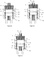
- FIGS. 1a, 1b and 1c describe the device of the invention in its basic version.
- Windows (14) of generally rectangular shape are formed along the circumference on the flap (7) to allow filling of the area (11).
- a simplified version of this system may be a skylight (7) without window where the catalyst can fill a larger part of the storage area (11) during cooling by the perforated part below the deflector.
- FIGS. 2a, 2b and 2c describe the device according to the invention in its variant where the flaps (7) move in fixed sleeves (12).
- the substantially vertical sleeve (12) is held either by hooking means (welding, bolts or other) to the supports (4), or by simply resting on the bottom of the reactor (1).
- Openings (16) are made at a level between the lower end of the baskets (5) and the top of the sheath (12).
- Windows (16) for example of rectangular shape, are also made in the upper part of the sleeve (12) on a part of the circumference or on the whole.
- a deflector (15) is welded, or attached in any manner known to those skilled in the art, to the lower part of the sheath (12). It may have the shape of an inclined plane or a curved wall, all around the circumference of the sheath (12) or only a part.
- the Figure 2c corresponds to the resumption of circulation and the emptying of the storage area (11).
- the deflector (15) allows the catalyst to flow out of the storage zone (11) when the reactor is restarted. During this restart, the reactor returns to its operating temperature, and the catalyst circulates again. Gradually, the basket (5) down again closing the access to the windows (16), the storage area (11) empties completely little by little, operation facilitated by the presence of the deflector (15).
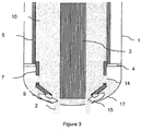
- the figure 3 is a representation of the device according to the invention in which there is shown a flap (7) whose end portion is inclined relative to the vertical, this flap ending in the deflector (15) whose inclination is substantially the same as that the end part of the flap (7).
- This temporary storage zone (11) must be positioned in such a way that the recirculation of the catalyst is close to the circulation legs (2) of the reactor.
- the present invention may be described as a catalytic reactor employing a ring-shaped moving bed catalyst, limited at its outer periphery by vertical walls forming a cylindrical basket (5), and at its inner periphery by a central collector. (3) also vertical, the catalyst being in gravity flow slow in the space between the basket (5) and the central collector (3), and flowing downwards via circulation legs (2) located on the substantially hemispherical bottom of said reactor.
- the basket (5) is movable along a substantially vertical axis over a distance of a few centimeters up to 10 cm, this basket (5) being provided with bibs (7) themselves substantially vertical, located at the bottom of the basket (5), in the extension of the vertical wall of said flap (7).
- the latter may experience an interruption of the flow of the catalyst, causing a drop in temperature of the reaction chamber and a compression of the catalyst which causes the walls and the various internal mechanical stresses that can be very high .
- the present invention consists in equipping the reactor with means allowing a certain quantity of catalyst to move towards a temporary storage zone (11) to lower the level of these mechanical stresses, and then, in a second step, to empty the zone of storage to recirculate the temporarily stored catalyst.
- the present invention can therefore be defined as a catalytic reactor employing a ring-shaped moving bed catalyst, limited at its outer periphery by walls forming a cylindrical basket (5), and at its inner periphery by a central collector (3). ), the catalyst being in slow gravity flow in the space between the basket (5) and the central collector (3), and flowing downwardly via circulation legs (2) implanted on the bottom substantially hemispherical said reactor, said baskets being movable along a substantially vertical axis for a distance of a few centimeters, up to 10 cm, this basket (5) being provided with flaps (7) themselves substantially vertical, implanted on the lower part of the basket (5), in the extension of the wall of said flap (7).
- the reactor according to the present invention may have phases of stopping the circulation of the catalyst, whether it is voluntary or not.
- a space or storage zone (11) of the catalyst located in the lower part of the reactor adjacent to the wall, and close to the descent legs (2) is released by going back upwards the entire basket (5) and integral bibs (7).
- the storage zone (11) of the catalyst is located in the lower part of the reactor adjacent to the wall, and close to the descent legs (2). This storage area is released upwardly up the entire basket (5) and integral flaps (7), the flap (7) itself being provided with a deflector (15) which is rigidly or freely attached, and which forms with the vertical angle alpha between 30 and 60 °, preferably between 45 and 55 °.
- the deflector (15) is rigidly connected to the flap (7) and the flap (7) has an end portion, itself inclined relative to the vertical.
- the angle of inclination of the end portion of the flap (7) and the deflector (15) attached thereto are the same. This variant is represented figure 3 .
- the catalyst is recirculated by gravity as the circulation is reestablished, the storage zone (11) gradually emptying from the catalyst by means of the deflector (15).
- the catalyst is enclosed in annular baskets (5), the walls of which consist of grids allowing the charge to pass from the outside to the inside of the basket ( 5), then the reaction effluents from inside the basket (5) to the central collector (3).
- the charge thus circulates at a cross flow with respect to the catalyst in slow gravity flow, of the order of a few meters per hour.
- the flaps (7,) slide in fixed vertical sleeves (12) which are implanted in the extension of the vertical walls of the basket (5) and are provided with windows (14) obstructed by the sleeves ( 12) in normal circulation, said windows (14) being released during an elevation of the basket (5) following an interruption of the circulation of the catalyst.
- a certain amount of catalyst that can be evaluated at a percentage of the inventory between 0.2 and 5% passes through said windows (14) to the storage zone (11) located in the lower part of the reactor between the sleeve (12) and the wall of the hemispherical bottom of the reactor, and at a distance d greater than 30 cm from said wall.
- this part of the reactor can be modified to lengthen it by up to 1 meter.
- the windows (14) have a rectangular shape allowing regular entry of the catalyst into the storage area (11). They may also have a triangular shape, the tip of the triangle being directed upwards, so as to allow a gradual entry of the catalyst into the storage area (11).
- the invention is not related to the shape of windows (14) whose shape can be adjusted by the skilled person depending on the particularities of the reactor in question.
- the invention also relates to any refining or petrochemical process using the reactor according to any one of the preceding characteristics.
- the reactor according to the invention can be used in a catalytic reforming process for gasolines or in a process for the hydrotreatment of residues.
- the forces generated at the reactor walls are such that the upper part of the reactor rises, which can lead to the destruction of some internals, deformations of the Johnson grid, fixing bolts, and also the breakage of catalyst particles causing the creation fine particles causing additional pressure drops.
- the present invention describes a moving-bed catalytic reactor which makes it possible firstly to store a portion of the catalyst in a temporary storage zone and then, secondly, to re-circulate the stored catalyst.
- the invention is based on the existence of a movable basket (5) which is likely to rise vertically over a distance of a few cm, up to 10 cm, during a stoppage of catalyst circulation, and on existence of a deflector (15) attached to the walls (12) and forming an angle with the vertical to facilitate the emptying of the storage area during the recovery of circulation of the catalyst.
- the deflector (15) is positioned at the lower end of the sleeve (12) or the flap (7), and near the circulation legs (2) of the reactor.
- the term “near” a position shifted towards the vertical walls of the reactor (1) relative to the vertical axis of the descent legs (2) less than 10 cm and a distance "d" between said deflector and the point le closer to the reactor wall which is greater than or equal to 10 cm, this to avoid any jamming of the catalyst during emptying.
- the length of the deflector (15) must be sufficient to deflect the catalyst that descends into the basket (5), without being too important not to obstruct the window.
- a length of between 10 particle diameters and the half opening may be suitable so as not to significantly reduce the emptying window.
- the angle of the deflector must be large enough to deflect the catalyst, without being too much, not to stop it.
- the deflector (15) may be positioned in continuity with the wall of the sleeve (12) or the flap (7), or offset on one of the two sides of the wall to facilitate its attachment.
- the thickness of the deflector must be sufficient to withstand the weight of the catalyst that it supports and not to deform too much during thermal variations.
- a thickness equivalent to or greater than the wall of the basket is not more than twice the thickness of the wall of the basket (5).
- the shape of the storage area (11) in order to that the exit window is well positioned.
- the shape of the lower part of the flap (7) or the sleeve (12) can be modified so as to extend the flap (7) (or sheath (12) of the solution 2) respecting the shape of the bottom of the reactor (1).
- This portion (17) can be either fixed to the flap (7) and integral in its movements, or be movable relative to the vertical portion of the flap (7) or the sleeve (12). In this case, the lower part (17) must be fixed to the bottom of the reactor.
- An example of this extension is given on the figure 3a for solution 1.
- the following example gives the dimensioning of the storage zone and the deflector in the case of an industrial reforming reactor 14 m high and 2.7 m outside diameter.
- the circulation legs (2) have a diameter of 7 cm and the central collector a diameter of 1.2 m.
- the angle of inclination of the deflector (15) relative to the vertical is 53 °.
Landscapes
- Chemical & Material Sciences (AREA)
- Organic Chemistry (AREA)
- Chemical Kinetics & Catalysis (AREA)
- Oil, Petroleum & Natural Gas (AREA)
- Engineering & Computer Science (AREA)
- General Chemical & Material Sciences (AREA)
- Combustion & Propulsion (AREA)
- Devices And Processes Conducted In The Presence Of Fluids And Solid Particles (AREA)
- Production Of Liquid Hydrocarbon Mixture For Refining Petroleum (AREA)
- Hydrogen, Water And Hydrids (AREA)
- Physical Or Chemical Processes And Apparatus (AREA)
Claims (11)
- Katalytischer Reaktor, der einen Katalysator im ringförmigen Fließbett einsetzt, der an seiner äußeren Peripherie durch Wände, die einen zylindrischen Korb (5) bilden, und an seiner inneren Peripherie durch einen zentralen Kollektor (3) begrenzt ist, wobei sich der schwerkraftbedingt langsam fließende Katalysator in dem Raum befindet, der zwischen dem Korb (5) und dem zentralen Kollektor (3) enthalten ist, und nach unten mit Hilfe von Zirkulationsbeinen (2) zirkuliert, die auf dem im Wesentlichen halbkugelförmigen Boden des Reaktors eingebaut sind, wobei die Körbe entlang einer im Wesentlichen vertikalen Achse über eine Distanz von einigen Zentimetern, die bis zu 10 cm reichen kann, beweglich sind, wobei dieser Korb (5) mit Klappen (7) versehen ist, die selbst im Wesentlichen vertikal sind, im unteren Teil des Korbs (5) in der Verlängerung der Wand der Klappe (7) eingebaut sind, wobei bei dem Reaktor bei einer Unterbrechung der Zirkulation des Katalysators ein Speicherraum (11) des Katalysators, der sich im unteren Teil des Reaktors, der an die Wand angrenzt, und nahe zu den Abstiegsbeinen (2) befindet, freigeben wird, wobei er die Einheit des Korbs (5) und der verbundenen Klappen (7) nach oben zieht, wobei die Klappe (7) selbst mit einem Abweiser (15) versehen ist, der mit ihm starr oder frei verbunden ist und mit der Vertikalen einen Winkel Alpha zwischen 30 und 60°, vorzugsweise zwischen 45 und 55°, bildet.
- Katalytischer Reaktor nach Anspruch 1, bei dem der Abweiser (15) starr mit der Klappe (7) verbunden ist.
- Katalytischer Reaktor nach Anspruch 1, wobei der Katalysator durch Schwerkraft wieder in Zirkulation versetzt wird, sobald die Zirkulation wieder hergestellt ist, wobei sich die Speicherzone (11) progressiv aus dem Katalysator mit Hilfe des Abweisers (15) leert.
- Katalytischer Reaktor im Fließbett nach einem der Ansprüche 1 oder 3, wobei der Katalysator in Körbe (5) von ringförmiger Form eingeschlossen ist, deren Wände von Gittern gebildet sind, die die Charge von außen in das Innere des Korbs (5), dann die Reaktorabflüsse vom Inneren des Korbs (5) zu einem zentralen Kollektor (3) durchlassen.
- Katalytischer Reaktor im Fließbett nach einem der Ansprüche 1 bis 4, bei dem die Klappen (7) in festen vertikalen Hülsen (12) gleiten, die in der Verlängerung der vertikalen Wände des Korbs (5) eingebaut und mit Fenstern (14) versehen sind, die durch die Hülsen (12) bei normaler Zirkulation verschlossen sind, wobei die Fenster (14) bei einer Anhebung des Korbs (5) nach einer Unterbrechung der Zirkulation freigegeben werden, wodurch der Durchgang des Katalysators durch die Fenster (14) zu der Speicherzone (11) möglich ist, die sich im unteren Teil des Reaktors zwischen der Hülse (12) und der Wand des halbkugelförmigen Bodens des Reaktors und in einem Abstand d von mehr als 10 cm zur Wand befindet.
- Katalytischer Reaktor im Fließbett nach einem der Ansprüche 1 bis 5, bei dem die Klappen (7) oder vertikalen Hülsen (12) durch eine Wand (15) verlängert sein können, die es ermöglicht, den Ausgang, durch den der Katalysator aus der Zone (11) gemäß des Pfeils (9) austritt, der Vertikalen des Ablaufbeins (2) anzunähern.
- Katalytischer Reaktor im Fließbett nach einem der Ansprüche 1 bis 6, bei dem die Fenster (14) eine rechteckige Form haben, die einen regelmäßigen Einlauf des Katalysators in die Speicherzone (11) ermöglicht.
- Katalytischer Reaktor im Fließbett nach einem der Ansprüche 1 bis 6, bei dem die Fenster (14) eine dreieckige Form haben, wobei die Spitze des Dreiecks nach oben gerichtet ist, um einen progressiven Einlauf des Katalysators in die Speicherzone (11) zu ermöglichen.
- Raffinerie- und Petrochemieverfahren, das den Reaktor nach einem der Ansprüche 1 bis 8 verwendet.
- Katalytisches Reformierungsverfahren der Essenzen, das den Reaktor nach einem der Ansprüche 1 bis 8 verwendet.
- Verfahren zur Hydrobehandlung von Reststoffen, das den Reaktor nach einem der Ansprüche 1 bis 8 verwendet.
Applications Claiming Priority (1)
| Application Number | Priority Date | Filing Date | Title |
|---|---|---|---|
| FR1662637A FR3060414B1 (fr) | 2016-12-16 | 2016-12-16 | Dispositif permettant le stockage temporaire et la remise en circulation d'une certaine quantite de catalyseur dans les unites de reformage catalytique. |
Publications (2)
| Publication Number | Publication Date |
|---|---|
| EP3335784A1 EP3335784A1 (de) | 2018-06-20 |
| EP3335784B1 true EP3335784B1 (de) | 2019-08-07 |
Family
ID=57909772
Family Applications (1)
| Application Number | Title | Priority Date | Filing Date |
|---|---|---|---|
| EP17206290.3A Active EP3335784B1 (de) | 2016-12-16 | 2017-12-08 | Fliessbett für katalytische reformierung |
Country Status (6)
| Country | Link |
|---|---|
| US (1) | US10300448B2 (de) |
| EP (1) | EP3335784B1 (de) |
| CN (1) | CN108201865B (de) |
| BR (1) | BR102017026758B1 (de) |
| FR (1) | FR3060414B1 (de) |
| RU (1) | RU2747994C2 (de) |
Families Citing this family (1)
| Publication number | Priority date | Publication date | Assignee | Title |
|---|---|---|---|---|
| CN115337869A (zh) * | 2022-08-03 | 2022-11-15 | 李巍 | 一种内部催化剂可快速回收的化工反应罐 |
Family Cites Families (14)
| Publication number | Priority date | Publication date | Assignee | Title |
|---|---|---|---|---|
| US3873441A (en) * | 1973-09-06 | 1975-03-25 | Universal Oil Prod Co | Catalyst transfer method for moving-bed reactors |
| US4040794A (en) * | 1975-10-24 | 1977-08-09 | Uop Inc. | Moving bed contacting process and apparatus |
| US4141690A (en) * | 1977-08-05 | 1979-02-27 | Uop Inc. | Catalytic reaction chamber for gravity-flowing catalyst particles |
| US4567023A (en) * | 1984-02-27 | 1986-01-28 | Uop Inc. | Multiple-stage reactor system for a moving catalyst bed |
| DE4238717A1 (de) * | 1992-07-02 | 1994-01-13 | Bergwerksverband Gmbh | Schüttgutreaktor mit im unteren Reaktorbereich angeordneten dachförmigen Schüttgutverteilerböden und steuerbaren Abzugsvorrichtungen |
| US5360535A (en) * | 1993-09-02 | 1994-11-01 | Texaco Inc. | Ebullated bed process with recycle eductor |
| EP0711331A4 (de) * | 1994-04-29 | 1998-03-25 | Chevron Usa Inc | Katalysator, methode und gerät für ein system zum ersatz von teilchen für gegenstromkontakt zwischen einem einsatz und einem schüttgutbett |
| CN1158136C (zh) * | 1999-06-10 | 2004-07-21 | 环球油品公司 | 使反应剂与间断式移动催化剂床接触的方法和设备 |
| DE10260733B4 (de) * | 2002-12-23 | 2010-08-12 | Outokumpu Oyj | Verfahren und Anlage zur Wärmebehandlung von eisenoxidhaltigen Feststoffen |
| JP4922685B2 (ja) * | 2006-07-12 | 2012-04-25 | 財団法人 国際石油交流センター | 混合装置 |
| FR2966751B1 (fr) * | 2010-10-28 | 2013-11-08 | IFP Energies Nouvelles | Nouvelle grille externe modulaire pour les reacteurs a lits radiaux. |
| CN103506055B (zh) * | 2012-06-21 | 2015-08-12 | 中国石油化工集团公司 | 一种逆流移动床连续重整反应器反应物料密封装置及方法 |
| FR3017806B1 (fr) * | 2014-02-27 | 2016-02-26 | Axens | Reacteur catalytique en lit mobile permettant de faire face a des interruptions de circulation du catalyseur et procede utilisant ledit reacteur |
| FR3025439B1 (fr) * | 2014-09-10 | 2018-05-11 | IFP Energies Nouvelles | Regenerateur apte a regenerer des catalyseurs dans des conditions operatoires differentes |
-
2016
- 2016-12-16 FR FR1662637A patent/FR3060414B1/fr not_active Expired - Fee Related
-
2017
- 2017-12-08 EP EP17206290.3A patent/EP3335784B1/de active Active
- 2017-12-12 BR BR102017026758-0A patent/BR102017026758B1/pt active IP Right Grant
- 2017-12-14 RU RU2017143823A patent/RU2747994C2/ru active
- 2017-12-15 CN CN201711349624.4A patent/CN108201865B/zh active Active
- 2017-12-15 US US15/843,000 patent/US10300448B2/en active Active
Non-Patent Citations (1)
| Title |
|---|
| None * |
Also Published As
| Publication number | Publication date |
|---|---|
| CN108201865B (zh) | 2022-02-25 |
| RU2017143823A (ru) | 2019-06-14 |
| FR3060414B1 (fr) | 2019-01-25 |
| US10300448B2 (en) | 2019-05-28 |
| RU2017143823A3 (de) | 2021-03-15 |
| EP3335784A1 (de) | 2018-06-20 |
| BR102017026758A2 (pt) | 2018-10-30 |
| CN108201865A (zh) | 2018-06-26 |
| BR102017026758B1 (pt) | 2022-02-15 |
| FR3060414A1 (fr) | 2018-06-22 |
| RU2747994C2 (ru) | 2021-05-18 |
| US20180169601A1 (en) | 2018-06-21 |
Similar Documents
| Publication | Publication Date | Title |
|---|---|---|
| CA2715915C (fr) | Dispositif de chargement de particules de catalyseur dans des tubes presentant une zone annulaire | |
| CA1180882A (fr) | Procede et dispositif pour soutirer des particules solides et introduire une charge liquide a la partie inferieure d'une zone de contact | |
| EP3374073A1 (de) | Filterungs- und verteilungsvorrichtung für einen katalytischen reaktor | |
| EP3335784A1 (de) | Fliessbett für katalytische reformierung | |
| FR2490616A1 (fr) | Convertisseur d'anhydride sulfureux gazeux en anhydride sulfurique gazeux et support de catalyseur pour ce convertisseur | |
| EP0907187A1 (de) | Wasserkernreaktor dessen Druckgefäss eine Auffangvorrichtung der Spaltzone nach einem Schmelzunfall enthält | |
| CA2884946A1 (fr) | Systeme de chargement dense du catalyseur dans des tubes a baionnette pour reacteur echangeur de vaporeformage faisant appel a des elements helicoidaux amovibles | |
| EP3110540B1 (de) | Wirbelbettkatalysator zur ermöglichung der handhabung von unterbrechungen im fluss des katalysators und verfahren mit diesem reaktor | |
| CA2884943A1 (fr) | Systeme pneumatique de chargement dense de catalyseur dans des tubes a baionnette pour reacteur echangeur de vaporeformage | |
| EP2908933B1 (de) | System für dichte katalysatorbeladung in bajonettröhren für einen dampfreformierungsreaktor-tauscher | |
| FR3043339A1 (fr) | Dispositif de filtration et de distribution pour reacteur catalytique | |
| CA3020940A1 (fr) | Panier amovible pour reacteur catalytique | |
| EP2938562B1 (de) | Vorrichtung zur vermeidung von flüssigkeitsüberlauf von einer externen flüssigen lagereinrichtung, lagereinrichtung, verwendung, verfahren | |
| FR3028426A1 (fr) | Conduit de collecte pour un reacteur radial comprenant des filets pleins. | |
| EP3215248B1 (de) | Vorrichtung zum abschöpfen von oberflächenflüssigkeit | |
| EP0064430B1 (de) | Absorberstab für Kernreaktor | |
| EP1640062B1 (de) | Katalytischer Festbettreaktor mit Bypass mittels durch das Bett und Verfahren mit Verwendung dieser Vorrichtung | |
| FR2602977A1 (fr) | Procede et dispositif d'extinction d'une nappe de feu dans un liquide inflammable | |
| FR2981956A1 (fr) | Dispositif de remontee de sediments situes dans les fonds marins | |
| FR3052367A1 (fr) | Reacteur catalytique radial multitubulaire | |
| EP0398814B1 (de) | Vorrichtung zum Extrahieren von Materialteilchen aus einem Wirbelbett aus einem Wirbelbettgefäss | |
| FR3117895A1 (fr) | Enceinte de separation et de stripage avec une grille de filtration de debris | |
| FR2924699A1 (fr) | Dispositif pour le transport de particules, installation et procede pour le chargement d'une enceinte avec le dispositif | |
| BE1024894B1 (fr) | Systeme de stockage et separation pour generateur de vapeur industriel | |
| FR2791172A1 (fr) | Installation de protection pour centrale nucleaire |
Legal Events
| Date | Code | Title | Description |
|---|---|---|---|
| PUAI | Public reference made under article 153(3) epc to a published international application that has entered the european phase |
Free format text: ORIGINAL CODE: 0009012 |
|
| STAA | Information on the status of an ep patent application or granted ep patent |
Free format text: STATUS: THE APPLICATION HAS BEEN PUBLISHED |
|
| AK | Designated contracting states |
Kind code of ref document: A1 Designated state(s): AL AT BE BG CH CY CZ DE DK EE ES FI FR GB GR HR HU IE IS IT LI LT LU LV MC MK MT NL NO PL PT RO RS SE SI SK SM TR |
|
| AX | Request for extension of the european patent |
Extension state: BA ME |
|
| STAA | Information on the status of an ep patent application or granted ep patent |
Free format text: STATUS: REQUEST FOR EXAMINATION WAS MADE |
|
| 17P | Request for examination filed |
Effective date: 20181220 |
|
| RBV | Designated contracting states (corrected) |
Designated state(s): AL AT BE BG CH CY CZ DE DK EE ES FI FR GB GR HR HU IE IS IT LI LT LU LV MC MK MT NL NO PL PT RO RS SE SI SK SM TR |
|
| GRAP | Despatch of communication of intention to grant a patent |
Free format text: ORIGINAL CODE: EPIDOSNIGR1 |
|
| STAA | Information on the status of an ep patent application or granted ep patent |
Free format text: STATUS: GRANT OF PATENT IS INTENDED |
|
| INTG | Intention to grant announced |
Effective date: 20190305 |
|
| GRAS | Grant fee paid |
Free format text: ORIGINAL CODE: EPIDOSNIGR3 |
|
| GRAA | (expected) grant |
Free format text: ORIGINAL CODE: 0009210 |
|
| STAA | Information on the status of an ep patent application or granted ep patent |
Free format text: STATUS: THE PATENT HAS BEEN GRANTED |
|
| AK | Designated contracting states |
Kind code of ref document: B1 Designated state(s): AL AT BE BG CH CY CZ DE DK EE ES FI FR GB GR HR HU IE IS IT LI LT LU LV MC MK MT NL NO PL PT RO RS SE SI SK SM TR |
|
| REG | Reference to a national code |
Ref country code: GB Ref legal event code: FG4D Free format text: NOT ENGLISH |
|
| REG | Reference to a national code |
Ref country code: CH Ref legal event code: EP Ref country code: AT Ref legal event code: REF Ref document number: 1162978 Country of ref document: AT Kind code of ref document: T Effective date: 20190815 |
|
| REG | Reference to a national code |
Ref country code: DE Ref legal event code: R096 Ref document number: 602017005942 Country of ref document: DE |
|
| REG | Reference to a national code |
Ref country code: IE Ref legal event code: FG4D Free format text: LANGUAGE OF EP DOCUMENT: FRENCH |
|
| REG | Reference to a national code |
Ref country code: NL Ref legal event code: FP |
|
| REG | Reference to a national code |
Ref country code: LT Ref legal event code: MG4D |
|
| PG25 | Lapsed in a contracting state [announced via postgrant information from national office to epo] |
Ref country code: PT Free format text: LAPSE BECAUSE OF FAILURE TO SUBMIT A TRANSLATION OF THE DESCRIPTION OR TO PAY THE FEE WITHIN THE PRESCRIBED TIME-LIMIT Effective date: 20191209 Ref country code: NO Free format text: LAPSE BECAUSE OF FAILURE TO SUBMIT A TRANSLATION OF THE DESCRIPTION OR TO PAY THE FEE WITHIN THE PRESCRIBED TIME-LIMIT Effective date: 20191107 Ref country code: SE Free format text: LAPSE BECAUSE OF FAILURE TO SUBMIT A TRANSLATION OF THE DESCRIPTION OR TO PAY THE FEE WITHIN THE PRESCRIBED TIME-LIMIT Effective date: 20190807 Ref country code: HR Free format text: LAPSE BECAUSE OF FAILURE TO SUBMIT A TRANSLATION OF THE DESCRIPTION OR TO PAY THE FEE WITHIN THE PRESCRIBED TIME-LIMIT Effective date: 20190807 Ref country code: LT Free format text: LAPSE BECAUSE OF FAILURE TO SUBMIT A TRANSLATION OF THE DESCRIPTION OR TO PAY THE FEE WITHIN THE PRESCRIBED TIME-LIMIT Effective date: 20190807 Ref country code: FI Free format text: LAPSE BECAUSE OF FAILURE TO SUBMIT A TRANSLATION OF THE DESCRIPTION OR TO PAY THE FEE WITHIN THE PRESCRIBED TIME-LIMIT Effective date: 20190807 Ref country code: BG Free format text: LAPSE BECAUSE OF FAILURE TO SUBMIT A TRANSLATION OF THE DESCRIPTION OR TO PAY THE FEE WITHIN THE PRESCRIBED TIME-LIMIT Effective date: 20191107 |
|
| REG | Reference to a national code |
Ref country code: AT Ref legal event code: MK05 Ref document number: 1162978 Country of ref document: AT Kind code of ref document: T Effective date: 20190807 |
|
| PG25 | Lapsed in a contracting state [announced via postgrant information from national office to epo] |
Ref country code: AL Free format text: LAPSE BECAUSE OF FAILURE TO SUBMIT A TRANSLATION OF THE DESCRIPTION OR TO PAY THE FEE WITHIN THE PRESCRIBED TIME-LIMIT Effective date: 20190807 Ref country code: LV Free format text: LAPSE BECAUSE OF FAILURE TO SUBMIT A TRANSLATION OF THE DESCRIPTION OR TO PAY THE FEE WITHIN THE PRESCRIBED TIME-LIMIT Effective date: 20190807 Ref country code: ES Free format text: LAPSE BECAUSE OF FAILURE TO SUBMIT A TRANSLATION OF THE DESCRIPTION OR TO PAY THE FEE WITHIN THE PRESCRIBED TIME-LIMIT Effective date: 20190807 Ref country code: IS Free format text: LAPSE BECAUSE OF FAILURE TO SUBMIT A TRANSLATION OF THE DESCRIPTION OR TO PAY THE FEE WITHIN THE PRESCRIBED TIME-LIMIT Effective date: 20191207 Ref country code: RS Free format text: LAPSE BECAUSE OF FAILURE TO SUBMIT A TRANSLATION OF THE DESCRIPTION OR TO PAY THE FEE WITHIN THE PRESCRIBED TIME-LIMIT Effective date: 20190807 |
|
| REG | Reference to a national code |
Ref country code: GR Ref legal event code: EP Ref document number: 20190403433 Country of ref document: GR Effective date: 20200213 |
|
| PG25 | Lapsed in a contracting state [announced via postgrant information from national office to epo] |
Ref country code: TR Free format text: LAPSE BECAUSE OF FAILURE TO SUBMIT A TRANSLATION OF THE DESCRIPTION OR TO PAY THE FEE WITHIN THE PRESCRIBED TIME-LIMIT Effective date: 20190807 |
|
| PG25 | Lapsed in a contracting state [announced via postgrant information from national office to epo] |
Ref country code: IT Free format text: LAPSE BECAUSE OF FAILURE TO SUBMIT A TRANSLATION OF THE DESCRIPTION OR TO PAY THE FEE WITHIN THE PRESCRIBED TIME-LIMIT Effective date: 20190807 Ref country code: RO Free format text: LAPSE BECAUSE OF FAILURE TO SUBMIT A TRANSLATION OF THE DESCRIPTION OR TO PAY THE FEE WITHIN THE PRESCRIBED TIME-LIMIT Effective date: 20190807 Ref country code: PL Free format text: LAPSE BECAUSE OF FAILURE TO SUBMIT A TRANSLATION OF THE DESCRIPTION OR TO PAY THE FEE WITHIN THE PRESCRIBED TIME-LIMIT Effective date: 20190807 Ref country code: DK Free format text: LAPSE BECAUSE OF FAILURE TO SUBMIT A TRANSLATION OF THE DESCRIPTION OR TO PAY THE FEE WITHIN THE PRESCRIBED TIME-LIMIT Effective date: 20190807 Ref country code: EE Free format text: LAPSE BECAUSE OF FAILURE TO SUBMIT A TRANSLATION OF THE DESCRIPTION OR TO PAY THE FEE WITHIN THE PRESCRIBED TIME-LIMIT Effective date: 20190807 Ref country code: AT Free format text: LAPSE BECAUSE OF FAILURE TO SUBMIT A TRANSLATION OF THE DESCRIPTION OR TO PAY THE FEE WITHIN THE PRESCRIBED TIME-LIMIT Effective date: 20190807 |
|
| PG25 | Lapsed in a contracting state [announced via postgrant information from national office to epo] |
Ref country code: SM Free format text: LAPSE BECAUSE OF FAILURE TO SUBMIT A TRANSLATION OF THE DESCRIPTION OR TO PAY THE FEE WITHIN THE PRESCRIBED TIME-LIMIT Effective date: 20190807 Ref country code: IS Free format text: LAPSE BECAUSE OF FAILURE TO SUBMIT A TRANSLATION OF THE DESCRIPTION OR TO PAY THE FEE WITHIN THE PRESCRIBED TIME-LIMIT Effective date: 20200224 Ref country code: SK Free format text: LAPSE BECAUSE OF FAILURE TO SUBMIT A TRANSLATION OF THE DESCRIPTION OR TO PAY THE FEE WITHIN THE PRESCRIBED TIME-LIMIT Effective date: 20190807 Ref country code: CZ Free format text: LAPSE BECAUSE OF FAILURE TO SUBMIT A TRANSLATION OF THE DESCRIPTION OR TO PAY THE FEE WITHIN THE PRESCRIBED TIME-LIMIT Effective date: 20190807 |
|
| REG | Reference to a national code |
Ref country code: DE Ref legal event code: R097 Ref document number: 602017005942 Country of ref document: DE |
|
| PLBE | No opposition filed within time limit |
Free format text: ORIGINAL CODE: 0009261 |
|
| STAA | Information on the status of an ep patent application or granted ep patent |
Free format text: STATUS: NO OPPOSITION FILED WITHIN TIME LIMIT |
|
| PG2D | Information on lapse in contracting state deleted |
Ref country code: IS |
|
| 26N | No opposition filed |
Effective date: 20200603 |
|
| PG25 | Lapsed in a contracting state [announced via postgrant information from national office to epo] |
Ref country code: MC Free format text: LAPSE BECAUSE OF FAILURE TO SUBMIT A TRANSLATION OF THE DESCRIPTION OR TO PAY THE FEE WITHIN THE PRESCRIBED TIME-LIMIT Effective date: 20190807 Ref country code: SI Free format text: LAPSE BECAUSE OF FAILURE TO SUBMIT A TRANSLATION OF THE DESCRIPTION OR TO PAY THE FEE WITHIN THE PRESCRIBED TIME-LIMIT Effective date: 20190807 |
|
| PG25 | Lapsed in a contracting state [announced via postgrant information from national office to epo] |
Ref country code: LU Free format text: LAPSE BECAUSE OF NON-PAYMENT OF DUE FEES Effective date: 20191208 Ref country code: IE Free format text: LAPSE BECAUSE OF NON-PAYMENT OF DUE FEES Effective date: 20191208 |
|
| PG25 | Lapsed in a contracting state [announced via postgrant information from national office to epo] |
Ref country code: CY Free format text: LAPSE BECAUSE OF FAILURE TO SUBMIT A TRANSLATION OF THE DESCRIPTION OR TO PAY THE FEE WITHIN THE PRESCRIBED TIME-LIMIT Effective date: 20190807 |
|
| PG25 | Lapsed in a contracting state [announced via postgrant information from national office to epo] |
Ref country code: HU Free format text: LAPSE BECAUSE OF FAILURE TO SUBMIT A TRANSLATION OF THE DESCRIPTION OR TO PAY THE FEE WITHIN THE PRESCRIBED TIME-LIMIT; INVALID AB INITIO Effective date: 20171208 Ref country code: MT Free format text: LAPSE BECAUSE OF FAILURE TO SUBMIT A TRANSLATION OF THE DESCRIPTION OR TO PAY THE FEE WITHIN THE PRESCRIBED TIME-LIMIT Effective date: 20190807 |
|
| REG | Reference to a national code |
Ref country code: CH Ref legal event code: PL |
|
| PG25 | Lapsed in a contracting state [announced via postgrant information from national office to epo] |
Ref country code: LI Free format text: LAPSE BECAUSE OF NON-PAYMENT OF DUE FEES Effective date: 20201231 Ref country code: CH Free format text: LAPSE BECAUSE OF NON-PAYMENT OF DUE FEES Effective date: 20201231 |
|
| PG25 | Lapsed in a contracting state [announced via postgrant information from national office to epo] |
Ref country code: MK Free format text: LAPSE BECAUSE OF FAILURE TO SUBMIT A TRANSLATION OF THE DESCRIPTION OR TO PAY THE FEE WITHIN THE PRESCRIBED TIME-LIMIT Effective date: 20190807 |
|
| GBPC | Gb: european patent ceased through non-payment of renewal fee |
Effective date: 20211208 |
|
| PG25 | Lapsed in a contracting state [announced via postgrant information from national office to epo] |
Ref country code: GB Free format text: LAPSE BECAUSE OF NON-PAYMENT OF DUE FEES Effective date: 20211208 |
|
| PGFP | Annual fee paid to national office [announced via postgrant information from national office to epo] |
Ref country code: FR Payment date: 20251223 Year of fee payment: 9 Ref country code: NL Payment date: 20251222 Year of fee payment: 9 |
|
| PGFP | Annual fee paid to national office [announced via postgrant information from national office to epo] |
Ref country code: GR Payment date: 20251218 Year of fee payment: 9 |
|
| PGFP | Annual fee paid to national office [announced via postgrant information from national office to epo] |
Ref country code: DE Payment date: 20251229 Year of fee payment: 9 |
|
| PGFP | Annual fee paid to national office [announced via postgrant information from national office to epo] |
Ref country code: BE Payment date: 20260109 Year of fee payment: 9 |