EP3335568B1 - Device and method for producing a liquid or semi-liquid food product - Google Patents
Device and method for producing a liquid or semi-liquid food product Download PDFInfo
- Publication number
- EP3335568B1 EP3335568B1 EP17195875.4A EP17195875A EP3335568B1 EP 3335568 B1 EP3335568 B1 EP 3335568B1 EP 17195875 A EP17195875 A EP 17195875A EP 3335568 B1 EP3335568 B1 EP 3335568B1
- Authority
- EP
- European Patent Office
- Prior art keywords
- mixture
- degasser
- pressure
- pump
- supply device
- Prior art date
- Legal status (The legal status is an assumption and is not a legal conclusion. Google has not performed a legal analysis and makes no representation as to the accuracy of the status listed.)
- Active
Links
- 239000007788 liquid Substances 0.000 title claims description 34
- 238000004519 manufacturing process Methods 0.000 title claims description 13
- 235000021057 semi-liquid food Nutrition 0.000 title description 17
- 235000021056 liquid food Nutrition 0.000 title description 16
- 239000000203 mixture Substances 0.000 claims description 193
- 235000013399 edible fruits Nutrition 0.000 claims description 25
- 238000000034 method Methods 0.000 claims description 18
- 239000007787 solid Substances 0.000 claims description 17
- 238000007872 degassing Methods 0.000 claims description 9
- 238000006073 displacement reaction Methods 0.000 claims description 7
- 238000011049 filling Methods 0.000 claims description 7
- 238000000605 extraction Methods 0.000 claims 2
- 239000007789 gas Substances 0.000 description 70
- 239000002002 slurry Substances 0.000 description 39
- 235000013305 food Nutrition 0.000 description 31
- QVGXLLKOCUKJST-UHFFFAOYSA-N atomic oxygen Chemical compound [O] QVGXLLKOCUKJST-UHFFFAOYSA-N 0.000 description 15
- 239000001301 oxygen Substances 0.000 description 15
- 229910052760 oxygen Inorganic materials 0.000 description 15
- 238000011161 development Methods 0.000 description 12
- 230000018109 developmental process Effects 0.000 description 12
- 235000011389 fruit/vegetable juice Nutrition 0.000 description 12
- 239000010408 film Substances 0.000 description 8
- CURLTUGMZLYLDI-UHFFFAOYSA-N Carbon dioxide Chemical compound O=C=O CURLTUGMZLYLDI-UHFFFAOYSA-N 0.000 description 6
- 235000015203 fruit juice Nutrition 0.000 description 6
- 238000009434 installation Methods 0.000 description 6
- XLYOFNOQVPJJNP-UHFFFAOYSA-N water Substances O XLYOFNOQVPJJNP-UHFFFAOYSA-N 0.000 description 6
- 239000011261 inert gas Substances 0.000 description 5
- 230000001105 regulatory effect Effects 0.000 description 5
- IJGRMHOSHXDMSA-UHFFFAOYSA-N Atomic nitrogen Chemical compound N#N IJGRMHOSHXDMSA-UHFFFAOYSA-N 0.000 description 4
- 244000052616 bacterial pathogen Species 0.000 description 4
- 238000003860 storage Methods 0.000 description 4
- 238000007669 thermal treatment Methods 0.000 description 4
- 235000013361 beverage Nutrition 0.000 description 3
- 239000001569 carbon dioxide Substances 0.000 description 3
- 229910002092 carbon dioxide Inorganic materials 0.000 description 3
- 230000001419 dependent effect Effects 0.000 description 3
- 239000011552 falling film Substances 0.000 description 3
- 230000033001 locomotion Effects 0.000 description 3
- 238000002156 mixing Methods 0.000 description 3
- UFHFLCQGNIYNRP-UHFFFAOYSA-N Hydrogen Chemical compound [H][H] UFHFLCQGNIYNRP-UHFFFAOYSA-N 0.000 description 2
- 230000033228 biological regulation Effects 0.000 description 2
- 238000010586 diagram Methods 0.000 description 2
- ZINJLDJMHCUBIP-UHFFFAOYSA-N ethametsulfuron-methyl Chemical compound CCOC1=NC(NC)=NC(NC(=O)NS(=O)(=O)C=2C(=CC=CC=2)C(=O)OC)=N1 ZINJLDJMHCUBIP-UHFFFAOYSA-N 0.000 description 2
- 230000005484 gravity Effects 0.000 description 2
- 239000001257 hydrogen Substances 0.000 description 2
- 229910052739 hydrogen Inorganic materials 0.000 description 2
- 239000004615 ingredient Substances 0.000 description 2
- 229910052757 nitrogen Inorganic materials 0.000 description 2
- 230000001590 oxidative effect Effects 0.000 description 2
- 238000005086 pumping Methods 0.000 description 2
- 235000015067 sauces Nutrition 0.000 description 2
- 238000013022 venting Methods 0.000 description 2
- 235000013618 yogurt Nutrition 0.000 description 2
- 238000010923 batch production Methods 0.000 description 1
- 230000015572 biosynthetic process Effects 0.000 description 1
- 229910052799 carbon Inorganic materials 0.000 description 1
- 238000004140 cleaning Methods 0.000 description 1
- 239000000470 constituent Substances 0.000 description 1
- 238000011109 contamination Methods 0.000 description 1
- 230000001276 controlling effect Effects 0.000 description 1
- 230000007423 decrease Effects 0.000 description 1
- 230000006735 deficit Effects 0.000 description 1
- 230000006866 deterioration Effects 0.000 description 1
- 238000004090 dissolution Methods 0.000 description 1
- 238000005516 engineering process Methods 0.000 description 1
- 230000004941 influx Effects 0.000 description 1
- 230000005764 inhibitory process Effects 0.000 description 1
- 235000021579 juice concentrates Nutrition 0.000 description 1
- 238000002372 labelling Methods 0.000 description 1
- 239000012528 membrane Substances 0.000 description 1
- 238000010943 off-gassing Methods 0.000 description 1
- 238000002360 preparation method Methods 0.000 description 1
- 238000004064 recycling Methods 0.000 description 1
- 230000000630 rising effect Effects 0.000 description 1
- 235000014347 soups Nutrition 0.000 description 1
- 239000000725 suspension Substances 0.000 description 1
- 238000009423 ventilation Methods 0.000 description 1
Images


Classifications
-
- A—HUMAN NECESSITIES
- A23—FOODS OR FOODSTUFFS; TREATMENT THEREOF, NOT COVERED BY OTHER CLASSES
- A23L—FOODS, FOODSTUFFS, OR NON-ALCOHOLIC BEVERAGES, NOT COVERED BY SUBCLASSES A21D OR A23B-A23J; THEIR PREPARATION OR TREATMENT, e.g. COOKING, MODIFICATION OF NUTRITIVE QUALITIES, PHYSICAL TREATMENT; PRESERVATION OF FOODS OR FOODSTUFFS, IN GENERAL
- A23L2/00—Non-alcoholic beverages; Dry compositions or concentrates therefor; Their preparation
- A23L2/52—Adding ingredients
- A23L2/54—Mixing with gases
-
- A—HUMAN NECESSITIES
- A23—FOODS OR FOODSTUFFS; TREATMENT THEREOF, NOT COVERED BY OTHER CLASSES
- A23C—DAIRY PRODUCTS, e.g. MILK, BUTTER OR CHEESE; MILK OR CHEESE SUBSTITUTES; MAKING THEREOF
- A23C7/00—Other dairy technology
- A23C7/04—Removing unwanted substances other than lactose or milk proteins from milk
-
- A—HUMAN NECESSITIES
- A23—FOODS OR FOODSTUFFS; TREATMENT THEREOF, NOT COVERED BY OTHER CLASSES
- A23C—DAIRY PRODUCTS, e.g. MILK, BUTTER OR CHEESE; MILK OR CHEESE SUBSTITUTES; MAKING THEREOF
- A23C9/00—Milk preparations; Milk powder or milk powder preparations
- A23C9/12—Fermented milk preparations; Treatment using microorganisms or enzymes
- A23C9/13—Fermented milk preparations; Treatment using microorganisms or enzymes using additives
- A23C9/133—Fruit or vegetables
-
- A—HUMAN NECESSITIES
- A23—FOODS OR FOODSTUFFS; TREATMENT THEREOF, NOT COVERED BY OTHER CLASSES
- A23L—FOODS, FOODSTUFFS, OR NON-ALCOHOLIC BEVERAGES, NOT COVERED BY SUBCLASSES A21D OR A23B-A23J; THEIR PREPARATION OR TREATMENT, e.g. COOKING, MODIFICATION OF NUTRITIVE QUALITIES, PHYSICAL TREATMENT; PRESERVATION OF FOODS OR FOODSTUFFS, IN GENERAL
- A23L2/00—Non-alcoholic beverages; Dry compositions or concentrates therefor; Their preparation
- A23L2/02—Non-alcoholic beverages; Dry compositions or concentrates therefor; Their preparation containing fruit or vegetable juices
-
- A—HUMAN NECESSITIES
- A23—FOODS OR FOODSTUFFS; TREATMENT THEREOF, NOT COVERED BY OTHER CLASSES
- A23L—FOODS, FOODSTUFFS, OR NON-ALCOHOLIC BEVERAGES, NOT COVERED BY SUBCLASSES A21D OR A23B-A23J; THEIR PREPARATION OR TREATMENT, e.g. COOKING, MODIFICATION OF NUTRITIVE QUALITIES, PHYSICAL TREATMENT; PRESERVATION OF FOODS OR FOODSTUFFS, IN GENERAL
- A23L2/00—Non-alcoholic beverages; Dry compositions or concentrates therefor; Their preparation
- A23L2/52—Adding ingredients
-
- A—HUMAN NECESSITIES
- A23—FOODS OR FOODSTUFFS; TREATMENT THEREOF, NOT COVERED BY OTHER CLASSES
- A23L—FOODS, FOODSTUFFS, OR NON-ALCOHOLIC BEVERAGES, NOT COVERED BY SUBCLASSES A21D OR A23B-A23J; THEIR PREPARATION OR TREATMENT, e.g. COOKING, MODIFICATION OF NUTRITIVE QUALITIES, PHYSICAL TREATMENT; PRESERVATION OF FOODS OR FOODSTUFFS, IN GENERAL
- A23L2/00—Non-alcoholic beverages; Dry compositions or concentrates therefor; Their preparation
- A23L2/70—Clarifying or fining of non-alcoholic beverages; Removing unwanted matter
- A23L2/76—Clarifying or fining of non-alcoholic beverages; Removing unwanted matter by removal of gases
-
- A—HUMAN NECESSITIES
- A23—FOODS OR FOODSTUFFS; TREATMENT THEREOF, NOT COVERED BY OTHER CLASSES
- A23L—FOODS, FOODSTUFFS, OR NON-ALCOHOLIC BEVERAGES, NOT COVERED BY SUBCLASSES A21D OR A23B-A23J; THEIR PREPARATION OR TREATMENT, e.g. COOKING, MODIFICATION OF NUTRITIVE QUALITIES, PHYSICAL TREATMENT; PRESERVATION OF FOODS OR FOODSTUFFS, IN GENERAL
- A23L23/00—Soups; Sauces; Preparation or treatment thereof
-
- A—HUMAN NECESSITIES
- A23—FOODS OR FOODSTUFFS; TREATMENT THEREOF, NOT COVERED BY OTHER CLASSES
- A23L—FOODS, FOODSTUFFS, OR NON-ALCOHOLIC BEVERAGES, NOT COVERED BY SUBCLASSES A21D OR A23B-A23J; THEIR PREPARATION OR TREATMENT, e.g. COOKING, MODIFICATION OF NUTRITIVE QUALITIES, PHYSICAL TREATMENT; PRESERVATION OF FOODS OR FOODSTUFFS, IN GENERAL
- A23L5/00—Preparation or treatment of foods or foodstuffs, in general; Food or foodstuffs obtained thereby; Materials therefor
- A23L5/20—Removal of unwanted matter, e.g. deodorisation or detoxification
-
- B—PERFORMING OPERATIONS; TRANSPORTING
- B01—PHYSICAL OR CHEMICAL PROCESSES OR APPARATUS IN GENERAL
- B01D—SEPARATION
- B01D19/00—Degasification of liquids
- B01D19/0036—Flash degasification
-
- B—PERFORMING OPERATIONS; TRANSPORTING
- B01—PHYSICAL OR CHEMICAL PROCESSES OR APPARATUS IN GENERAL
- B01D—SEPARATION
- B01D19/00—Degasification of liquids
- B01D19/0068—General arrangements, e.g. flowsheets
Definitions
- the present invention relates to an apparatus and a method for producing a liquid or semi-liquid food, in particular fruit juices with fruit pieces.
- the international patent application WO 2015/162041 A1 discloses a device according to a modified twin-flow method in which the portion containing the fruit pieces is supplied to the juice before the thermal treatment, but after the degasser.
- the present invention is therefore an object of the invention to provide an apparatus and a method for the production of liquid or semi-liquid food available, which allows a gentle treatment of dosed pieces with low installation costs and low operating costs.
- a device for producing a liquid or semi-liquid food wherein the food comprises a first mixture and a second mixture, wherein the second mixture contains solid fractions, in particular pieces of fruit, in a higher concentration than the first mixture with a degasser configured to at least partially degas the first mixture, a first supply device for supplying the first mixture to the degasser and a second supply device for dosing the second mixture for at least partially degassing the first mixture, the second supply device being in a negative pressure region of the first mixture Entgasers or in a negative pressure region downstream of the degasser opens.
- liquid or semi-liquid foods are to be understood as fruit juices which contain fruit pieces of one or more fruits.
- liquid or semi-liquid foodstuffs according to the present invention also includes sauces, salsa, soups, jams and yoghurts which have a solid portion in the form of pieces.
- the liquid or semi-liquid food comprises a first mixture and a second mixture, the second mixture containing solid fractions, in particular fruit pieces, in a higher concentration than the first mixture.
- the first mixture also has solid fractions.
- the present invention is particularly applicable to those foods in which the first mixture is free of solid ingredients, especially pieces of fruit, wherein the solid ingredients are added to the first mixture by admixing the second mixture.
- the second mixture which comprises the solid constituents, is also referred to as slurry, even if the foodstuff is not fruit juices. Accordingly becomes The first mixture also called juice, even if the food is not fruit juices.
- the first mixture may have 80 to 95% water.
- the first mixture may have 6 to 18% sugar.
- liquid components are conceivable for the first mixture.
- the second mixture may be in addition to the solid components, i. Bits, in particular water, wherein the mass ratio of water and solid components may be about 1: 1.
- the second mixture can be added to the first mixture in the ratio of 1:15 to 1: 2, preferably 1:12 to 1: 4 for the preparation of the food.
- the pieces may have a diameter in the range of 1 to 10 mm, preferably 1 to 5 mm.
- Zudosage or metering The addition of the slurry to the first mixture is referred to here and below as Zudosage or metering.
- the device comprises a degasser, which is designed to at least partially degas the first mixture.
- Degasers are well known in the art.
- the removal of the undesired gases from the product to be degassed is usually carried out by negative pressure, wherein in addition a stripping gas can be used to expel the unwanted gases, for example oxygen, from the product to be degassed.
- the degasser has an inlet for the product to be degassed, through which the product can be introduced into a container, for example a tank or a column, of the degasser.
- the product can either be introduced continuously into the degasser or the container can be filled in the sense of a batch process with a predetermined amount of product, which is then degassed.
- a stripping gas may also be introduced into an interior of the degasser via a stripping gas supply line of the degasifier.
- the stripping gas before introduction of the product, i. of the first mixture are added to the degasser this or introduced directly into the interior of the degasser.
- the degasifier, and in particular an interior of the container or of the column can be designed such that a well-defined atmosphere, that is, in the container or the column. In particular, an atmosphere with well-defined pressure and / or composition can be produced.
- the stripping gas may be hydrogen or a hydrogen-containing gas, carbon dioxide or a carbon dioxide-containing gas, an inert gas, for example nitrogen, or another suitable gas, as well as a combination of the aforementioned gases.
- the stripping gas is sterile and free of water vapor.
- the degasser can, for example by appropriate arrangement of the inlet for the product to be degassed, the outlet for the at least partially degassed product, the supply line for the stripping gas and / or the discharge line for the stripping gas, be designed such that the stripping gas is passed through the degasser in countercurrent to the product to be degassed.
- a particularly large surface area of the product to be degassed can be achieved, for example, by forming the degasser as a film gasifier, in particular as a trickle-bed gasifier.
- the product which is at least partially degassed, collects in a bottom area of the degasser up to a filling level predetermined by the control technology, from which it can be withdrawn, for example, by means of a pump.
- this bottom region of the degasser including the outlet for the at least partially degassed product, is referred to as the outlet region of the degasser.
- the device has a first supply device for supplying the first mixture to the degasser.
- the first supply device for example, have a line for the first mixture, which opens into the degasser, in particular in an upper region of the degasser.
- the first supply device may additionally comprise a reservoir for the first mixture, a pump for conveying the first mixture and / or further required devices, such as controllable valves or sensors.
- the device has a second supply device for metering the second mixture to the at least partially degassed first mixture.
- the second supply device is thus designed such that the second mixture is not supplied to the first mixture until it has already passed through the degasser.
- the second mixture is not supplied to the first mixture before entering the degasser and also not introduced directly into the above-mentioned well-defined atmosphere above the level.
- the second supply device is designed such that it opens into a negative pressure region of the degasser or in a negative pressure region downstream of the degasser.
- the second supply device may also have a corresponding line which opens into the negative pressure region of the degasser or downstream of the degasser into a negative pressure region.
- the second feed device can have further components, for example the reservoir described below and pumps, which serve to supply the slurry.
- the negative pressure region of the degasifier here and below comprises the entire interior of the degasifier, which is brought to a negative pressure, for example by means of a vacuum pump suitable for this purpose.
- the negative pressure region of the degasser also includes the outlet region described above, since the at least partially degassed first mixture is also subject to a pressure in the outlet region which is less than the ambient pressure. Accordingly, there is also in a connected to the outlet of the degasser exhaust pipe for the at least partially degassed product so far a pressure that is less than the ambient pressure is until the hydrodynamic pressure is raised by a pressure-increasing device back to the ambient pressure or a higher pressure.
- the downstream of the degasser arranged vacuum region thus comprises the area between the outlet of the degasser and the feed pump or the high heater.
- the second supply device opens into a negative pressure region of the degasifier or into a negative pressure region downstream of the degasser
- a single high-temperature heater can be used in order to sterilize the entire food.
- the device described thus has the advantage of Einstromvons that the system can be simplified and thus causes lower installation costs, while at the same time the majority of the product can be freed of oxygen and unwanted damage to the added pieces are avoided by the pressure reduction during passage through the degasser ,
- the pressure in the supply line to the degasser for the first mixture for example by means of a throttle valve, to a negative pressure of for example 200 mbar to 600 mbar, preferably 200 mbar to 400 mbar, reduced.
- This negative pressure also prevails in the atmosphere above the level of the at least partially degassed first mixture in the degasser.
- the second supply device can open into an outlet of the degasser for the at least partially degassed first mixture.
- the second supply device can open into an outlet of the degasser for the at least partially degassed first mixture.
- the degasser In the actual interior of the degasser, ie including the bottom region in which collects the at least partially degassed first mixture, thus there is no second mixture. Since the at least partially degassed first mixture in the outlet of the degasser is still under negative pressure, the metered addition of the second mixture into the outlet of the degasser causes the pieces of undesirable gases can be freed.
- the outlet of the degasser can be designed and arranged in such a way that the gases withdrawn from the piece rise through the outlet into the interior of the degasser, from where they can be pumped off, for example, by means of a vacuum pump.
- the prevailing pressure in the outlet of the degasifier is greater than in the atmosphere in the degasifier, so that the metered addition can take place gently.
- the entire food can be degassed without the pieces would be destroyed.
- the second supply device may open into the degasser below the above-mentioned level of food accumulating in a bottom area of the degasser.
- the metered addition of the second mixture already takes place in the degasser, so that the ready-mixed food accumulates in the bottom area.
- the negative pressure present in the atmosphere is correspondingly increased by the height of the liquid column above the mouth. The pressure difference between the ambient pressure and the pressure at the mouth of the second supply device to be overcome is thus reduced compared to the introduction of the second mixture into the vacuum atmosphere of the degasser.
- the second mixture can be added gentle to the product, while at the same time the dosed pieces can be largely degassed.
- the mouth of the second supply device may be arranged, for example, 50 cm to 400 cm, preferably 100 cm to 200 cm, below a predetermined control level in the degasser. This leads to an increase of the pressure by 50 mbar to 400 mbar, preferably by 100 mbar to 200 mbar.
- the bottom region of the degasser can be designed correspondingly cylindrical or cylindroconical.
- the second supply device can open into a discharge line connected to the degasser.
- the feeder i. a line of the feeder, thus in the negative pressure area between the outlet of the degasser and a point of the discharge line at which the pressure is raised to the ambient pressure or above.
- This may be, for example, a feed pump in the discharge line.
- a siphon can be provided between the degasser and the point of the junction of the second supply device, which prevents pieces introduced via the second supply device from getting back into the degasifier, where they could be driven up due to their gas content.
- About a vent valve forming gas bubbles can be removed in the siphon. It may be advantageous to connect the vent valve with the atmosphere of the degasser or with the vacuum pump of the degasser.
- the second supply device can have a storage container, in particular a mixing tank, which is designed to provide the second mixture with a pre-pressure which is greater than the pressure in the negative-pressure region.
- the reservoir can already be placed under pressure during filling or held by means of suitable devices at a pressure which is greater than the pressure in the vacuum range.
- a sterile gas such as an inert gas, may be pumped into the reservoir to produce a desired pressure.
- the pressure in the reservoir can be specified in particular such that a promotion of the second mixture in the second supply device via the pressure difference between the form and the pressure in the vacuum region.
- This can also be achieved by using a controllable valve, in particular a poppet valve, which draws in a function of the discharged from the reservoir amount of slurry sterile foreign gas or an inert gas and thus ensures that the form in the reservoir a constant value, for example the ambient pressure, has.
- the second delivery device may be configured such that delivery of the second mixture in the second delivery device occurs via the pressure difference between the admission pressure and the pressure in the negative pressure region.
- the metered addition of second mixture to the first mixture in the vacuum region of the degasser or downstream of the degasser can be controlled in a particularly simple manner, for example by using a (controllable) metering valve, for example a throttle valve, in the supply line.
- the second supply device may have a pump for conveying the second mixture, in particular a positive displacement pump or a thrust pump, or a brake pump.
- a brake pump may in particular be provided as an alternative to the above-mentioned throttle valve, when the delivery of the second mixture in the supply line takes place substantially due to the pressure difference and / or the weight of the second mixture.
- the pressure of the conveyed through the brake pump through the second mixture is reduced by a drive movement of the brake pump.
- the brake pump thus acts as a hydraulic motor, which is driven by the pressurized second mixture and thereby degrades the pressure without narrow throttle gaps mainly on the associated with a rotary motion expansion.
- the pieces contained in the second mixture thus do not have to pass through narrow gaps. Rather, the second mixture can gently relax, so that the pieces suffer no damage and the brake pump itself is not exposed to any significant mechanical stress.
- the reservoir for the second mixture in the gravitational field of the earth can be arranged above the mouth of the second supply device, so that the weight of the second mixture contributes to the promotion of the second mixture.
- a pump for conveying the second mixture may be provided in the supply line.
- This pump may be designed in particular adjustable and be connected via signal lines or wirelessly with a corresponding control unit of the device.
- positive displacement pumps, eccentric screw pumps, piston pumps or membrane pumps can be used as a delivery pump, which can promote the solid components of the slurry without significant shear stress.
- the feed pump can be designed as a thrust pump. The feed pump can be controlled by means of the control unit such that the recipe-dependent amount of slurry is added to the first mixture.
- the device may also have a feed pump for conveying the first mixture in a feed line of the first feed device, which may also be designed to be adjustable.
- Rotary pumps for example rotary lobe pumps, centrifugal pumps or gear pumps, can be used for the delivery pump for the first mixture.
- the apparatus may further comprise a heater in the region of the first supply device, which is adapted to the first mixture before being supplied to the degasser to a temperature suitable for degassing, for example in the range of 50 ° C to 70 ° C, preferably in the range of 55 ° C to 65 ° C, in which the solubility of the unwanted gases in the liquid is reduced.
- the device according to the invention can be dispensed preheating of the slurry due to the admixture of the slurry downstream of the degasser or in the outlet region of the degasser.
- a device for the thermal treatment of the food to be produced in particular a Hocherhitzer or pasteurizer, be provided by means of which are killed in the liquid or semi-liquid food germs. Since high heaters, such as short-time heaters, and pasteurizers are well known in the art, a detailed description is omitted here. Unlike in the two-stream process, however, only a high-temperature heater or pasteurizer is required in the device according to the invention, so that installation costs and operating costs of the entire system can be saved.
- a method for producing a liquid or semi-liquid food wherein the food is a first mixture and a second mixture, wherein the second mixture contains solid fractions, in particular pieces of fruit, in a higher concentration than the first mixture, comprising the steps of: supplying the first mixture to a degasser; at least partial degassing of the first mixture in the degasser; and adding the second mixture to at least partially degassed first mixture; wherein the zudosage of the second mixture takes place in a negative pressure region of the degasser or in a negative pressure region downstream of the degasser.
- liquid or semi-liquid foods may be fruit juices containing fruit pieces of one or more fruits.
- the degassing of the first mixture in the degasser can be carried out as described by negative pressure, wherein in addition a stripping gas can be introduced into the degasser to drive out unwanted gases from the first mixture.
- the first mixture can be introduced from above into the degasifier, where it flows down in the form of a trickle film on the wall of the interior of the degasifier.
- the stripping gas can be introduced into the degasser from below, for example below a filling level of foodstuffs collecting in a bottom region of the degasifier, from where it flows counter to the descending first mixture to a stripping gas outlet in the upper region of the degasser, ie in a gas space above the level, flows.
- the undesired gases which have reached the first mixture at ambient pressure at least partially escape from the latter, in particular reducing the residual oxygen content of the foodstuffs to be produced. In this way, an oxidative impairment of food quality can be prevented.
- the at least partially degassed first mixture is withdrawn alone or after admixture of the second mixture via an outlet of the degasser.
- the negative pressure region of the degasifier in particular includes the interior of the degasser.
- the negative pressure region of the degasifier also includes the outlet region described above.
- the downstream of the degasser arranged vacuum region comprises as described the area between the outlet of the degasser and the feed pump or the high heater.
- the second mixture can be added to the first mixture in the ratio 1:15 to 1: 2, preferably 1:12 to 1: 4.
- the metered addition of the second mixture into an outlet of the degasser for the at least partially degassed first mixture can in particular take place in such a way, for example via the flow direction of the admixed second mixture with respect to the flow direction of the first mixture exiting via the outlet, that the pieces contained in the second mixture do not return to the degasser.
- the metered addition of the second mixture into the degasifier may occur below a level of food accumulating in a bottom region of the degasifier.
- the Zudosage example 50 cm to 400 cm, preferably 100 cm to 200 cm, below a rule technically predetermined level in the degasser may be arranged.
- the inventive method can thus include a control of the supply of the first mixture to the degasser and the withdrawal of the first mixture or food via the outlet of the degasser by means of suitable devices, such as controllable pumps and / or control valves, such that in the bottom region of the Deaerator sets a desired level of at least partially degassed first mixture or the food.
- the supply of first mixture to be degassed and / or stripping gas can be regulated as a function of a temperature of the first mixture to be degassed and of the composition of the first mixture and the stripping gas used.
- the metered addition of the second mixture into a discharge line connected to the degasser, in particular downstream of a downstream of the degasser arranged siphon take place.
- the above-described developments apply.
- the gas emerging from the admixed second mixture due to the negative pressure can be withdrawn via a valve and / or a pump from the upper region of the siphon.
- the food which is now mixed together, can be conveyed via an (adjustable) feed pump to a device for thermal treatment, for example a high-temperature heater or pasteurizer, in which the food is heated to a predetermined temperature, for example> 70 ° C., preferably> 80 ° C. is used to rid the food to be produced of germs.
- a device for thermal treatment for example a high-temperature heater or pasteurizer, in which the food is heated to a predetermined temperature, for example> 70 ° C., preferably> 80 ° C. is used to rid the food to be produced of germs.
- the spatial limit of the negative pressure range can be defined at the same time by increasing the hydrodynamic pressure of the conveyed food to the ambient pressure or an increased pressure desired for further processing by the delivery rate of the pump.
- the second mixture can be added at least partially due to a pressure difference between a supply pressure of the second mixture and the negative pressure in the negative pressure region.
- the delivery pressure may be adjusted as described above by controlled delivery of a sterile gas, such as an inert gas, to a reservoir for the second mixture. This can be achieved automatically by providing a sniffer valve or by controlling a corresponding pump or valve.
- a supply pressure can be provided which is greater than or equal to the ambient pressure.
- the pressure difference between the supply pressure and the pressure at the point at which the second mixture is mixed with the first mixture along a supply line for the second mixture automatically leads to a delivery of the second mixture to the negative pressure region of the degasifier or downstream of the degasser.
- This pressure-related delivery of the second mixture can be supported by the weight of the second mixture as described above.
- a delivery pump for the second mixture is thus not absolutely necessary.
- the second mixture can be at least partially metered by means of a pump, in particular a brake pump, a positive displacement pump or a thrust pump.
- the resistance of the brake pump can be controlled by a control unit such that depending on the above-mentioned pressure difference and / or the weight of the second mixture a desired for a particular recipe Zudosagemenge is added. If, as described above, the pressure difference and / or the dead weight of the second mixture are not sufficient for the delivery, the second mixture can be conveyed by means of a (controllable) positive displacement pump or thrust pump.
- the feed pump can be regulated in a recipe-dependent manner in order to ensure the desired metered addition of slurry to the first mixture.
- the second mixture can also be added at least partially by means of gravity.
- a reservoir for the second mixture in the gravitational field of the earth above an opening of a supply line for the second mixture may be provided to the first mixture.
- the addition of slurry to the first mixture can thus be effected solely by the pressure difference and / or the gravitational force and can be regulated alternatively or additionally via a feed pump.
- the Zudosage of the slurry in the negative pressure region of the degasser or downstream of the degasser arranged negative pressure area the Zudosage takes place in particular in front of a downstream Hocherhitzer or Pasteurizer instead. Therefore, the method according to the invention has the same advantages as the Einstrom psychologist with respect to the reduced installation and operating costs of the system used, while at the same time undesirable damage to the metered solid portions due to the pressure reduction can be avoided.
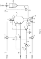
- FIG. 1 is a schematic diagram of an exemplary embodiment of an apparatus for producing liquid or semi-liquid foods according to the present invention shown.
- the illustrated apparatus combines the advantages of the one-stream method and the two-stream method for producing fruit drinks with fruit pieces.
- a first mixture 102 which is substantially free of fruit pieces is provided.
- the first mixture 102 may be, in particular, juice, which besides water may contain a sugar solution and a juice concentrate mixture.
- a second feeder 103 a second mixture 104 is simultaneously provided, which contains the fruit pieces to be added.
- the second mixture 104 the so-called slurry, may contain water or other liquids in addition to the fruit pieces.
- the first mixture 102 is first fed to a buffer or mixing tank 110, in which it is mixed.
- the first mixture 102 may be provided by means of a reservoir 110.
- the juice can be supplied to a preheater 120 in which it is heated, for example to 60 ° C.
- the preheated juice is introduced via a controllable valve 10 and a supply line 9 into the degasser 100.
- a device is provided, by means of which the supplied first mixture is expanded to a pressure below the ambient pressure. This can be achieved for example by means of a throttle valve at the inlet of the degasser 100, a reducing valve or a cross-sectional constriction in the supply line 9.
- the supplied first mixture of undesirable gases is at least partially degassed.
- a stripping gas from a source 170 via a supply line 14 and a controllable valve 11 are guided in countercurrent through the degasser 100.
- a vacuum pump 7 in a discharge line 13 for the enriched with the undesirable gases stripping gas 108 a well-defined negative pressure in the gas space of the degasser 100 can be adjusted.
- the withdrawn stripping gas 108 may either escape to the environment, be stored in a container for recycling, or be cleaned with a suitable device and returned to the source 170.
- the slurry 104 may also be supplied to a buffer 130. Alternatively, the slurry 104 may be provided in a storage tank or mixing tank 130. From there, the slurry can be added to the at least partially degassed first mixture by means of a pump 38 or without a pump (see below) in a vacuum region 180A of the degasifier 100 and / or a negative pressure region 180B downstream of the degasser 100. As in FIG. 1 The slurry is shown via supply lines 29 and 30 to the preheated, at least partially degassed juice in a vacuum region 180 of the device for producing liquid or semi-liquid food dosed.
- the negative pressure region 180 here comprises the negative pressure region 180A of the degasser 100 and the negative pressure region 180B downstream of the degasser.
- the negative pressure portion 180A of the degasser comprises the entire interior space as well as the outlet portion 100A of the degasifier, which are described in connection with FIGS FIGS. 2 and 3 will be described in more detail.
- the negative pressure region 180A begins at the pressure-reducing device, for example a reducing valve 10.
- the negative pressure region 180B ends spatially at a pressure-increasing device, for example the feed pump 18 in the discharge line 15 for the food.
- the first feeder 101 may include, in addition to lines 9 and valves 10, the reservoir 110 and the pre-heater 120 as well.
- the second supply device 103 in addition to lines 29 and 30 and pumps 38 and a reservoir 130 include. Other devices and features of the first and second delivery devices may be added as needed.
- the now ready-mixed food is fed to a high-temperature heater or pasteurizer 140, in which it is freed from unwanted germs.
- a high heater 140 is required, whereby installation and operating costs can be saved.
- the now pasteurized food can be fed to a bottling plant 160 for bottling the beverage into containers, such as bottles.
- Other common devices in the beverage industry such as labeling devices, coolers, storage devices or the like may be added as needed.
- the FIG. 2 schematically shows a degasser 100 and its outlet region 100A according to a first embodiment.
- the degasser 100 comprises a container 1, in particular a vacuum container, which comprises a lower region with a bottom whose diameter decreases downward.
- the bottom portion may be partially conical in particular.
- the container may for example have a volume of 1 m 3 to 5 m 3 .
- an inlet 2 is provided for the first mixture to be degassed, via which the first mixture is introduced into the container.
- the inlet 2 is provided with a distributor device 4, which is designed such that it generates a trickle film 19 to be degassed first mixture on a container inner surface.
- a falling film is understood here to mean a falling film which flows downwards in the direction of the outlet 3 on a container inner wall.
- the trickling film is formed below the distributor device 4 preferably rotationally symmetrical to the central axis M of the container 1.
- the trickle film can end, for example, in a liquid reservoir 42 in the lower region of the container 1.
- the trickle film thickness can, for example, in one area from 0.1 mm to 1 mm.
- the trickling film has a particularly large surface to the gas space 40 of the container 1, via which the gas exchange with the stripping gas can be particularly effective.
- a swirl inlet nozzle is provided as distributor device 4, which is designed to set the incoming first mixture into a rotational movement. This results in a thin, turbulent Rieselfilm 19, which flows over the entire container inner surface down.
- a double screen or a throttle device can also be used as distributor device 4.
- the degasser 100 also comprises a stripping gas feed line 5a in the lower region of the container and a stripping gas discharge line 6 in the upper region of the container.
- the stripping gas supply and discharge can produce a countercurrent 21 of stripping gas.
- the opening of the gas line 5a which is closed by a screen 35 for generating bubbles, is arranged at a height which is below a mirror surface 41, ie below the level, of the first mixture 42 accumulating in the bottom area of the degasser.
- the maximum level 41 can be set and adjusted by a level control.
- the stripping gas 21 can enter the first mixture and then into the gas space 40 of the container.
- the FIG. 2 further shows the feed line 29 for the slurry, which is arranged in the illustrated, non-limiting development such that the slurry is introduced into the bottom region of the degasser below the fill level 41. More specifically, the supply line 29 is arranged such that its mouth is a height H below the level 41. The weight of the standing above the mouth liquid column with height H raises the prevailing in the gas chamber 40 negative pressure to a value which is between the negative pressure and the ambient pressure. Thus, during metered addition of the slurry into the bottom area of the degasifier 100, a smaller pressure difference has to be overcome than in the single-stream method, in which the slurry enters the gas space 40 via the inlet 2 together with the first mixture.
- the addition of the slurry into the bottom area of the degasser is thus more gentle on the product than in the one-stream process.
- the Zudosage in the negative pressure range of the degasser also causes at least partial degassing of the entrained fruit pieces of unwanted gases.
- the supply line 29 as in the FIG. 2 be oriented in the direction of the general flow in the bottom area aligned.
- the spout area 100A includes the bottom area of the degasser including the spout 3 for the at least partially degassed product. That in the FIG. 3 shown alternative embodiment corresponds to that in the FIG. 2 embodiment shown with the exception that the opening 36 of the Strippgaszutechnisch 5 b above the surface 41 downwards, ie to the surface 41 of the accumulating in the bottom region of the container 1 first mixture 42, is directed.
- the opening 36 is preferably in the region of the central axis M of the container. If the stripping gas is introduced into the gas space 40 via a downwardly directed inflow opening, there is the advantage that the mirror surface 41 of the first mixture is also "blown off" in the lower region of the container, as a result of which more oxygen can be expelled.
- the formation of bubbles of the stripping gas rising in the liquid 42 promotes the dissolution of stripping gas in the first mixture and thus also the expulsion of oxygen.
- FIG. 4 schematically shows a device for metering the second mixture according to a first embodiment of the present invention.
- the stripping gas 105 is introduced via a line 14, a controllable valve 11 and the Strippgaszutechnisch 5 into the container 1 of the degasser 100 and by means of the controllable vacuum pump 7 via the Strippgasab réelle 6 and the line 13 as contaminated stripping gas 108 from the container. 1 deducted.
- the withdrawn, oxygen-enriched stripping gas 108 can be supplied to a device for removing oxygen.
- the first mixture 102 to be degassed is conducted to the inlet 2 and the distributor device 4.
- a controllable feed pump 37 may be provided in the supply line 9 for the first mixture, which is designed for example as a rotary pump.
- the falling down on the container inner wall trickling film collects in the lower part of the container 1, wherein in this area according to the embodiment shown, a pressure sensor 33 is provided, by means of which the level of liquid can be determined.
- the measured pressure is passed on to a controller 45, which controls the control valve 10 and / or the feed pump 37 in the line 9.
- the feed pump 37 the juice, for example, at a pressure of 5 bar in the supply line 9 promote, wherein the controllable reducing valve 10 causes a pressure reduction to the prevailing in the gas space of the degasser 200 mbar.
- a desired volume flow of juice can thus be set.
- the control valve 22 and / or the feed pump 18 can be adjusted in dependence on the measured pressure of the pressure sensor 33 such that a certain level is set in the bottom region of the degasser. With regulated level, the product to be degassed is then continuously added and discharged.
- a further control valve 46 may also be arranged, can be discarded via the liquid from the container (for example, cleaning liquid) via the channel 23.
- the amount of food removed can also take place via a regulation of the feed pump 18, wherein a control unit 24 is provided, which regulates the pumping capacity of the feed pump 18. It is also the feed pump 18 that spatially limits the vacuum area downstream of the degasser by raising the pressure of the food being withdrawn.
- the fill level control or regulation of the control valve 10 and the control of the vacuum pump 7 can also be carried out by the control unit 24. Even if it is in the FIG. 4 is not indicated by dashed lines, a central control unit 24 can also take over the control of other controllable valves and / or pumps.
- the control unit 24 in particular via a control of the control valve 11 and the control valve 10, the influx on stripping gas 105 and degassing first mixture 102 control such that an optimal outgassing of oxygen takes place from the falling film.
- the vacuum pump 7 can be controlled by the control unit 24 such that the partial pressure of oxygen in the atmosphere in the gas space of the container 1 is always so low that a predetermined residual content of oxygen is always exceeded in the withdrawn via the discharge line 15 food 106.
- the control unit 24 can make the control of the control valves 10 and 11 and the pumps 7 and 18 thereby using empirical waveforms, which guarantee a residual content of oxygen below a predetermined threshold.
- FIG. 4 shows a bypass valve 17 for demand-dependent bypassing the degasifier 100th
- the slurry 104 is metered into a bottom area of the degasser 100 via a feed line 29 of the second feed device.
- a flow meter 39 measures the volume flow of slurry in the line 29 and thus regulates a pump 38 in order to guarantee a formulation-like addition of slurry to the at least partially degassed first mixture.
- the illustrated pump 38 it can be a product-friendly feed pump, in particular a positive displacement pump or a thrust pump, which promotes the slurry without significant shear stress of the fruit pieces contained.
- the supply of slurry to the first mixture can also be carried out without delivery rate, ie, solely by the pressure difference and / or the own weight of the second mixture.
- the slurry 104 can be provided with the ambient pressure, so that a pressure difference of up to 800 mbar is set between the supply pressure of the slurry and the negative pressure region of the degasser.
- a controllable brake pump 38 may be provided in the supply line 29 in order to be able to control the amount of dosed slurry without a throttle flap.
- FIG. 5 is shown schematically an alternative development, which completely on the in the FIG. 4 shown pump 38 is omitted.
- a flow meter 39 is provided which measures the volume flow of slurry in the supply line 29.
- no pumping power is controlled based on the measured flow rate, but regulated a controllable vent valve 40 for the reservoir 130, in which the slurry, preferably in the gravitational field of the earth above the mouth of the supply line 29 in the outlet region of the degasser 100, is provided.
- the controllable ventilation valve 40 for example a sniffer valve
- the gas pressure in the gas space above the level of the slurry in the reservoir 130 can be adjusted to a desired value below the ambient pressure.
- the sniffer valve 40 may be connected to a supply line or a storage container for an inert gas 107, for example carbon dioxide or nitrogen.
- the reservoir 130 By targeted venting of the reservoir 130 can thus set a desired volume flow of slurry in the supply line 29.
- This volume flow can be adjusted according to the recipe selected the volume flow of juice in the supply line 9. Since the promotion of the slurry in the supply line 29 takes place solely due to the pressure difference between the pressure in the reservoir 130 and the pressure in the vacuum region at the mouth of the supply 29 in combination with the gravity of the slurry, can be completely dispensed with a feed pump.
- the use of the adjustable sniffer valve allows 40 also the waiver of a delivery inhibition by means of a brake pump or throttle.
- the devices shown allow to combine the advantages of the one-stream process with the advantages of the two-stream process in the production of liquid or semi-liquid foods.
- damage to the fruit pieces can be avoided by excessive pressure reduction in the degasifier, wherein the metering into the negative pressure area nevertheless allows at least partial degassing of the fruit pieces.
- the zudosage of the slurry in the negative pressure region of the device takes place particularly gentle on the product and as described above with reduced technical complexity, since it can be dispensed with a feed pump. This reduces not only the installation costs but also the operating costs of the system.
Description
Die vorliegende Erfindung betrifft eine Vorrichtung und ein Verfahren zur Herstellung eines flüssigen oder halbflüssigen Lebensmittels, insbesondere von Fruchtsäften mit Fruchtstücken.The present invention relates to an apparatus and a method for producing a liquid or semi-liquid food, in particular fruit juices with fruit pieces.
Heutzutage werden von der getränkeverarbeitenden Industrie und der Lebensmittelindustrie eine Vielzahl von flüssigen oder halbflüssigen Lebensmitteln bzw. Suspensionen angeboten, welche wenigstens einen festen Anteil in Form von Stückchen aufweisen. Beispiele sind insbesondere Fruchtsäfte, welche Fruchtstückchen einer oder mehrerer Früchte beinhalten. Andere Beispiele sind halbflüssige Lebensmittel mit festen Komponenten wie beispielsweise Saucen, Salsa oder Joghurte oder dergleichen. Dabei ist die Herstellung solcher Lebensmittel im Allgemeinen deutlich komplexer als die Herstellung homogener Getränke.Today, the beverage processing industry and the food industry offer a variety of liquid or semi-liquid foods or suspensions, which have at least a fixed proportion in the form of pieces. Examples are, in particular, fruit juices which contain fruit pieces of one or more fruits. Other examples are semi-liquid foods with solid components such as sauces, salsa or yoghurt or the like. The production of such foods is generally much more complex than the production of homogeneous drinks.
Im Stand der Technik bekannt ist die Herstellung nach dem sogenannten Einstromverfahren, bei dem dem homogenen Anteil ein die Stückchen enthaltender Anteil vor einer thermischen Behandlung des herzustellenden Lebensmittels beigemischt wird. Ebenso bekannt ist die Herstellung nach dem sogenannten Zweistromverfahren, bei dem der homogene Anteil, beispielsweise Saft, und der die Stückchen enthaltende Anteil getrennt voneinander thermisch behandelt, zum Beispiel pasteurisiert, werden und erst vor dem Füllen in einen sterilen Puffertank oder während des Füllens in einem Füllventil bzw. in dem Behälter, zum Beispiel einer Flasche, gemischt werden.Known in the prior art is the production according to the so-called Einstromverfahren, in which the homogenous portion containing a piece containing portion is added before a thermal treatment of the food to be produced. Also known is the production by the so-called Zweistromverfahren in which the homogeneous portion, such as juice, and containing the pieces thermally treated separately, for example, pasteurized, and only before filling in a sterile buffer tank or during filling in a Fill valve or in the container, for example, a bottle, are mixed.
Beide Konzepte weisen jedoch Nachteile auf. So kommt es beim Einstromverfahren im Entgaser, in dem das herzustellende Lebensmittel mittels Unterdrucks von Sauerstoff und anderen schädlichen Gasen befreit wird, durch den erforderlichen Druckabbau zu unerwünschten Beschädigungen an den mitgeführten Stückchen. Aus diesem Grund wird der feste Anteil üblicherweise am Entgaser vorbeigeführt, was jedoch aufgrund der in den festen Anteilen enthaltenen Gase zum Aufschwimmen der Stückchen in der Flasche und zu einer oxidativen Beeinträchtigung aufgrund des enthaltenen Sauerstoffs führen kann. Während das Zweistromverfahren diese Nachteile umgeht, ist es aufgrund des deutlich höheren apparativen Aufwands erheblich teurer.Both concepts, however, have disadvantages. So it comes with the Einstromverfahren in the degasser, in which the food to be produced is freed by means of negative pressure of oxygen and other harmful gases, by the required pressure reduction to undesirable damage to the entrained pieces. For this reason, the solid portion is usually passed by the degasifier, which however, due to the gases contained in the solid portions, can cause the chips in the bottle to float and cause oxidative deterioration due to the oxygen contained therein. While the Zweistromverfahren bypasses these disadvantages, it is considerably more expensive due to the significantly higher equipment cost.
Die internationale Patentanmeldung
Der vorliegenden Erfindung liegt somit die Aufgabe zugrunde, eine Vorrichtung und ein Verfahren zur Herstellung von flüssigen oder halbflüssigen Lebensmitteln zur Verfügung zu stellen, welche eine schonende Behandlung der zudosierten Stückchen bei gleichzeitig geringem Installationsaufwand und geringen Betriebskosten ermöglicht.The present invention is therefore an object of the invention to provide an apparatus and a method for the production of liquid or semi-liquid food available, which allows a gentle treatment of dosed pieces with low installation costs and low operating costs.
Die oben genannte Aufgabe wird gelöst durch eine Vorrichtung zur Herstellung eines flüssigen oder halbflüssigen Lebensmittels, wobei das Lebensmittel ein erstes Gemisch und ein zweites Gemisch umfasst, wobei das zweite Gemisch feste Anteile, insbesondere Fruchtstücke, in einer höheren Konzentration als das erste Gemisch enthält, mit einem Entgaser, der dazu ausgebildet ist, das erste Gemisch zumindest teilweise zu entgasen, einer ersten Zuführvorrichtung zum Zuführen des ersten Gemischs zum Entgaser und einer zweiten Zuführvorrichtung zum Zudosieren des zweiten Gemischs zum zumindest teilweise entgasten ersten Gemisch, wobei die zweite Zuführvorrichtung in einen Unterdruckbereich des Entgasers oder in einen Unterdruckbereich stromabwärts vom Entgaser mündet.The above object is achieved by a device for producing a liquid or semi-liquid food, wherein the food comprises a first mixture and a second mixture, wherein the second mixture contains solid fractions, in particular pieces of fruit, in a higher concentration than the first mixture with a degasser configured to at least partially degas the first mixture, a first supply device for supplying the first mixture to the degasser and a second supply device for dosing the second mixture for at least partially degassing the first mixture, the second supply device being in a negative pressure region of the first mixture Entgasers or in a negative pressure region downstream of the degasser opens.
Wie oben beschrieben sind unter flüssigen oder halbflüssigen Lebensmitteln insbesondere Fruchtsäfte zu verstehen, welche Fruchtstückchen einer oder mehrerer Früchte beinhalten. Ebenso sind von dem Begriff der flüssigen oder halbflüssigen Lebensmittel gemäß der vorliegenden Erfindung auch Saucen, Salsa, Suppen, Marmeladen und Joghurte umfasst, welche einen festen Anteil in Form von Stückchen aufweisen.As described above, liquid or semi-liquid foods are to be understood as fruit juices which contain fruit pieces of one or more fruits. Likewise, the term liquid or semi-liquid foodstuffs according to the present invention also includes sauces, salsa, soups, jams and yoghurts which have a solid portion in the form of pieces.
Erfindungsgemäß umfasst das flüssige oder halbflüssige Lebensmittel ein erstes Gemisch und ein zweites Gemisch, wobei das zweite Gemisch feste Anteile, insbesondere Fruchtstücke, in einer höheren Konzentration als das erste Gemisch enthält. Dies schließt nicht aus, dass auch das erste Gemisch feste Anteile aufweist. Die vorliegende Erfindung ist jedoch besonders auf solche Lebensmittel anwendbar, bei denen das erste Gemisch frei von festen Bestandteilen, insbesondere Fruchtstückchen, ist, wobei die festen Bestandteile durch Beimischen des zweiten Gemischs zum ersten Gemisch hinzugefügt werden. Der Einfachheit halber wird hier und im Folgenden das zweite Gemisch, das die festen Bestandteile umfasst, auch als Slurry bezeichnet, selbst wenn es sich bei dem Lebensmittel nicht um Fruchtsäfte handelt. Entsprechend wird das erste Gemisch auch als Saft bezeichnet, selbst wenn es sich bei dem Lebensmittel nicht um Fruchtsäfte handelt.According to the invention, the liquid or semi-liquid food comprises a first mixture and a second mixture, the second mixture containing solid fractions, in particular fruit pieces, in a higher concentration than the first mixture. This does not exclude that the first mixture also has solid fractions. However, the present invention is particularly applicable to those foods in which the first mixture is free of solid ingredients, especially pieces of fruit, wherein the solid ingredients are added to the first mixture by admixing the second mixture. For the sake of simplicity, here and below, the second mixture, which comprises the solid constituents, is also referred to as slurry, even if the foodstuff is not fruit juices. Accordingly becomes The first mixture also called juice, even if the food is not fruit juices.
Das erste Gemisch kann beispielsweise 80 bis 95 % Wasser aufweisen. Zusätzlich kann das erste Gemisch 6 bis 18 % Zucker aufweisen. Weitere, insbesondere flüssige Bestandteile sind für das erste Gemisch denkbar. Das zweite Gemisch kann neben den festen Bestandteilen, d.h. Stückchen, insbesondere Wasser aufweisen, wobei das Massenverhältnis von Wasser und festen Bestandteilen etwa 1:1 betragen kann. Das zweite Gemisch kann zur Herstellung des Lebensmittels dem ersten Gemisch im Verhältnis 1:15 bis 1:2, bevorzugt 1:12 bis 1:4 beigemischt werden. Die Stückchen können einen Durchmesser im Bereich von 1 bis 10 mm, bevorzugt 1 bis 5 mm aufweisen. Das Beimischen des Slurry zum ersten Gemisch wird hier und im Folgenden auch als Zudosage bzw. Zudosieren bezeichnet.For example, the first mixture may have 80 to 95% water. In addition, the first mixture may have 6 to 18% sugar. Further, in particular liquid components are conceivable for the first mixture. The second mixture may be in addition to the solid components, i. Bits, in particular water, wherein the mass ratio of water and solid components may be about 1: 1. The second mixture can be added to the first mixture in the ratio of 1:15 to 1: 2, preferably 1:12 to 1: 4 for the preparation of the food. The pieces may have a diameter in the range of 1 to 10 mm, preferably 1 to 5 mm. The addition of the slurry to the first mixture is referred to here and below as Zudosage or metering.
Die Vorrichtung umfasst einen Entgaser, der dazu ausgebildet ist, das erste Gemisch zumindest teilweise zu entgasen. Entgaser sind im Stand der Technik allgemein bekannt. Dabei erfolgt der Entzug der unerwünschten Gase aus dem zu entgasenden Produkt üblicherweise durch Unterdruck, wobei zusätzlich ein Strippgas eingesetzt werden kann, um die unerwünschten Gase, beispielsweise Sauerstoff, aus dem zu entgasenden Produkt auszutreiben. Hierzu weist der Entgaser einen Zulauf für das zu entgasende Produkt auf, durch den das Produkt in einen Behälter, beispielsweise einen Tank oder eine Kolonne, des Entgasers eingebracht werden kann. Dabei kann das Produkt entweder kontinuierlich in den Entgaser eingebracht werden oder der Behälter im Sinne einer Batchverarbeitung mit einer vorgegebenen Menge Produkt befüllt werden, welches anschließend entgast wird.The device comprises a degasser, which is designed to at least partially degas the first mixture. Degasers are well known in the art. The removal of the undesired gases from the product to be degassed is usually carried out by negative pressure, wherein in addition a stripping gas can be used to expel the unwanted gases, for example oxygen, from the product to be degassed. For this purpose, the degasser has an inlet for the product to be degassed, through which the product can be introduced into a container, for example a tank or a column, of the degasser. In this case, the product can either be introduced continuously into the degasser or the container can be filled in the sense of a batch process with a predetermined amount of product, which is then degassed.
Wie oben erwähnt kann zusätzlich zur Entgasung durch Reduzierung des Drucks in dem Entgaser auf einen Vakuumdruck auch ein Strippgas über eine Strippgaszuleitung des Entgasers in einen Innenraum des Entgasers eingebracht werden. Dabei kann das Strippgas vor Einbringen des Produkts, d.h. des ersten Gemischs, in den Entgaser diesem zugesetzt werden oder direkt in den Innenraum des Entgasers eingebracht werden. Hierzu kann der Entgaser, und insbesondere ein Innenraum des Behälters bzw. der Kolonne, derart ausgebildet sein, dass sich in dem Behälter bzw. der Kolonne eine wohldefinierte Atmosphäre, d.h. insbesondere eine Atmosphäre mit wohldefiniertem Druck und/oder Zusammensetzung, herstellen lässt. Bei dem Strippgas kann es sich um Wasserstoff oder ein wasserstoffhaltiges Gas, um Kohlendioxid oder ein kohlendioxidhaltiges Gas, um ein Inertgas, beispielsweise Stickstoff, oder ein anderes geeignetes Gas, sowie eine Kombination der zuvor genannten Gase handeln. Vorzugsweise ist das Strippgas steril und wasserdampffrei.As mentioned above, in addition to degassing by reducing the pressure in the degasifier to a vacuum pressure, a stripping gas may also be introduced into an interior of the degasser via a stripping gas supply line of the degasifier. In this case, the stripping gas before introduction of the product, i. of the first mixture are added to the degasser this or introduced directly into the interior of the degasser. For this purpose, the degasifier, and in particular an interior of the container or of the column, can be designed such that a well-defined atmosphere, that is, in the container or the column. In particular, an atmosphere with well-defined pressure and / or composition can be produced. The stripping gas may be hydrogen or a hydrogen-containing gas, carbon dioxide or a carbon dioxide-containing gas, an inert gas, for example nitrogen, or another suitable gas, as well as a combination of the aforementioned gases. Preferably, the stripping gas is sterile and free of water vapor.
Der Entgaser kann, beispielsweise durch entsprechende Anordnung des Zulaufs für das zu entgasende Produkt, des Auslaufs für das zumindest teilweise entgaste Produkt, der Zuleitung für das Strippgas und/oder der Abzugsleitung für das Strippgas, derart ausgebildet sein, dass das Strippgas im Gegenstrom zum zu entgasenden Produkt durch den Entgaser geführt wird. Eine besonders große Oberfläche des zu entgasenden Produkts lässt sich beispielsweise durch Ausbildung des Entgasers als Filmentgaser, insbesondere als Rieselfilmentgaser, erreichen. Im Allgemeinen sammelt sich das zumindest teilweise entgaste Produkt in einem Bodenbereich des Entgasers bis zu einem regeltechnisch vorgegebenen Füllstand, aus dem es beispielsweise mittels einer Pumpe abgezogen werden kann. Im Folgenden wird dieser Bodenbereich des Entgasers inklusive des Auslaufs für das zumindest teilweise entgaste Produkt als Auslaufbereich des Entgasers bezeichnet.The degasser can, for example by appropriate arrangement of the inlet for the product to be degassed, the outlet for the at least partially degassed product, the supply line for the stripping gas and / or the discharge line for the stripping gas, be designed such that the stripping gas is passed through the degasser in countercurrent to the product to be degassed. A particularly large surface area of the product to be degassed can be achieved, for example, by forming the degasser as a film gasifier, in particular as a trickle-bed gasifier. In general, the product, which is at least partially degassed, collects in a bottom area of the degasser up to a filling level predetermined by the control technology, from which it can be withdrawn, for example, by means of a pump. In the following, this bottom region of the degasser, including the outlet for the at least partially degassed product, is referred to as the outlet region of the degasser.
Erfindungsgemäß weist die Vorrichtung eine erste Zuführvorrichtung zum Zuführen des ersten Gemischs zum Entgaser auf. Hierzu kann die erste Zuführvorrichtung beispielsweise eine Leitung für das erste Gemisch aufweisen, welche in den Entgaser, insbesondere in einen oberen Bereich des Entgasers, mündet. Die erste Zuführvorrichtung kann zusätzlich einen Vorratsbehälter für das erste Gemisch, eine Pumpe zum Fördern des ersten Gemischs und/oder weitere benötigte Vorrichtungen, wie beispielsweise regelbare Ventile oder Sensoren, aufweisen.According to the invention, the device has a first supply device for supplying the first mixture to the degasser. For this purpose, the first supply device, for example, have a line for the first mixture, which opens into the degasser, in particular in an upper region of the degasser. The first supply device may additionally comprise a reservoir for the first mixture, a pump for conveying the first mixture and / or further required devices, such as controllable valves or sensors.
Des Weiteren weist die Vorrichtung eine zweite Zuführvorrichtung zum Zudosieren des zweiten Gemischs zum zumindest teilweise entgasten ersten Gemisch auf. Die zweite Zuführvorrichtung ist somit derart ausgebildet, dass das zweite Gemisch dem ersten Gemisch erst dann zugeführt wird, wenn dieses bereits im Wesentlichen durch den Entgaser hindurchgetreten ist. Insbesondere wird das zweite Gemisch dem ersten Gemisch nicht schon vor Eintritt in den Entgaser zugeführt und auch nicht direkt in die oben erwähnte wohldefinierte Atmosphäre über dem Füllstand eingebracht. Vielmehr ist die zweite Zuführvorrichtung derart ausgebildet, dass sie in einen Unterdruckbereich des Entgasers oder in einen Unterdruckbereich stromabwärts vom Entgaser mündet. Hierzu kann auch die zweite Zuführvorrichtung eine entsprechende Leitung aufweisen, die in den Unterdruckbereich des Entgasers oder stromabwärts vom Entgaser in einen Unterdruckbereich mündet. Wie auch die erste Zuführeinrichtung kann die zweite Zuführeinrichtung weitere Komponenten, beispielsweise den weiter unten beschriebenen Vorratsbehälter sowie Pumpen, aufweisen, welche der Zufuhr des Slurry dienen.Furthermore, the device has a second supply device for metering the second mixture to the at least partially degassed first mixture. The second supply device is thus designed such that the second mixture is not supplied to the first mixture until it has already passed through the degasser. In particular, the second mixture is not supplied to the first mixture before entering the degasser and also not introduced directly into the above-mentioned well-defined atmosphere above the level. Rather, the second supply device is designed such that it opens into a negative pressure region of the degasser or in a negative pressure region downstream of the degasser. For this purpose, the second supply device may also have a corresponding line which opens into the negative pressure region of the degasser or downstream of the degasser into a negative pressure region. Like the first feed device, the second feed device can have further components, for example the reservoir described below and pumps, which serve to supply the slurry.
Der Unterdruckbereich des Entgasers umfasst hier und im Folgenden den gesamten Innenraum des Entgasers, der, beispielsweise mittels einer hierzu geeigneten Vakuumpumpe, auf einen Unterdruck gebracht wird. Zusätzlich umfasst der Unterdruckbereich des Entgasers auch den oben beschriebenen Auslaufbereich, da das zumindest teilweise entgaste erste Gemisch auch im Auslaufbereich einem Druck unterliegt, der geringer als der Umgebungsdruck ist. Entsprechend liegt auch in einer mit dem Auslauf des Entgasers verbundenen Abzugsleitung für das zumindest teilweise entgaste Produkt so weit ein Druck vor, der geringer als der Umgebungsdruck ist, bis der hydrodynamische Druck durch eine den Druck erhöhende Vorrichtung wieder auf den Umgebungsdruck oder einen höheren Druck angehoben wird. Dies kann beispielsweise durch eine Förderpumpe in der Abzugsleitung oder ein Belüftungsventil einer nachgeordneten Vorrichtung, beispielsweise eines Hocherhitzers bzw. Pasteurisierers, mithilfe dessen das Lebensmittel von unerwünschten Keimen befreit wird, erfolgen. Der stromabwärts vom Entgaser angeordnete Unterdruckbereich umfasst somit den Bereich zwischen dem Auslauf des Entgasers und der Förderpumpe bzw. dem Hocherhitzer.The negative pressure region of the degasifier here and below comprises the entire interior of the degasifier, which is brought to a negative pressure, for example by means of a vacuum pump suitable for this purpose. In addition, the negative pressure region of the degasser also includes the outlet region described above, since the at least partially degassed first mixture is also subject to a pressure in the outlet region which is less than the ambient pressure. Accordingly, there is also in a connected to the outlet of the degasser exhaust pipe for the at least partially degassed product so far a pressure that is less than the ambient pressure is until the hydrodynamic pressure is raised by a pressure-increasing device back to the ambient pressure or a higher pressure. This can be done, for example, by a feed pump in the discharge line or a venting valve of a downstream device, for example a high-temperature heater or pasteurizer, with the aid of which the food is removed from unwanted germs. The downstream of the degasser arranged vacuum region thus comprises the area between the outlet of the degasser and the feed pump or the high heater.
Da die zweite Zuführvorrichtung in einen Unterdruckbereich des Entgasers oder in einen Unterdruckbereich stromabwärts vom Entgaser mündet, kann bei der erfindungsgemäßen Vorrichtung ein einziger Hocherhitzer verwendet werden, um das gesamte Lebensmittel keimfrei zu machen. Die beschriebene Vorrichtung weist somit den Vorteil des Einstromverfahrens auf, dass die Anlage vereinfacht werden kann und somit geringere Installationskosten verursacht, während gleichzeitig der Großteil des Produktes von Sauerstoff befreit werden kann und unerwünschte Beschädigungen der zugesetzten Stückchen durch den Druckabbau beim Durchgang durch den Entgaser vermieden werden.Since the second supply device opens into a negative pressure region of the degasifier or into a negative pressure region downstream of the degasser, in the device according to the invention a single high-temperature heater can be used in order to sterilize the entire food. The device described thus has the advantage of Einstromverfahrens that the system can be simplified and thus causes lower installation costs, while at the same time the majority of the product can be freed of oxygen and unwanted damage to the added pieces are avoided by the pressure reduction during passage through the degasser ,
Während in der zweiten Zuführvorrichtung beispielsweise der Umgebungsdruck herrscht, kann der Druck in der Zuleitung zum Entgaser für das erste Gemisch, beispielsweise mittels eines Drosselventils, auf einen Unterdruck von beispielsweise 200 mbar bis 600 mbar, bevorzugt 200 mbar bis 400 mbar, reduziert werden. Dieser Unterdruck herrscht dabei auch in der Atmosphäre über dem Füllstand des zumindest teilweise entgasten ersten Gemischs im Entgaser.While in the second supply device, for example, the ambient pressure prevails, the pressure in the supply line to the degasser for the first mixture, for example by means of a throttle valve, to a negative pressure of for example 200 mbar to 600 mbar, preferably 200 mbar to 400 mbar, reduced. This negative pressure also prevails in the atmosphere above the level of the at least partially degassed first mixture in the degasser.
Gemäß einer Weiterbildung kann die zweite Zuführvorrichtung in einen Auslauf des Entgasers für das zumindest teilweise entgaste erste Gemisch münden. Bei dieser Weiterbildung mündet beispielsweise eine Leitung der zweiten Zuführvorrichtung in den Auslauf des Entgasers. Im eigentlichen Innenraum des Entgasers, d. h. inklusive des Bodenbereichs, in dem sich das zumindest teilweise entgaste erste Gemisch sammelt, befindet sich somit kein zweites Gemisch. Da das zumindest teilweise entgaste erste Gemisch im Auslauf des Entgasers weiterhin unter Unterdruck steht, führt das Zudosieren des zweiten Gemischs in den Auslauf des Entgasers dazu, dass die Stückchen von unerwünschten Gasen befreit werden können. Der Auslauf des Entgasers kann dabei derart ausgebildet und angeordnet sein, dass die den Stückchen entzogenen Gase durch den Auslauf in den Innenraum des Entgasers aufsteigen, von wo aus sie beispielsweise mittels einer Vakuumpumpe abgepumpt werden können. Gleichzeitig ist der vorherrschende Druck im Auslauf des Entgasers jedoch größer als in der Atmosphäre im Entgaser, sodass das Zudosieren produktschonend erfolgen kann. Somit kann das gesamte Lebensmittel entgast werden, ohne dass die Stückchen zerstört würden.According to a development, the second supply device can open into an outlet of the degasser for the at least partially degassed first mixture. In this development, for example, opens a line of the second feeder into the outlet of the degasser. In the actual interior of the degasser, ie including the bottom region in which collects the at least partially degassed first mixture, thus there is no second mixture. Since the at least partially degassed first mixture in the outlet of the degasser is still under negative pressure, the metered addition of the second mixture into the outlet of the degasser causes the pieces of undesirable gases can be freed. The outlet of the degasser can be designed and arranged in such a way that the gases withdrawn from the piece rise through the outlet into the interior of the degasser, from where they can be pumped off, for example, by means of a vacuum pump. At the same time, however, the prevailing pressure in the outlet of the degasifier is greater than in the atmosphere in the degasifier, so that the metered addition can take place gently. Thus, the entire food can be degassed without the pieces would be destroyed.
Alternativ kann die zweite Zuführvorrichtung in den Entgaser unterhalb des oben genannten Füllstands von sich in einem Bodenbereich des Entgasers ansammelndem Lebensmittel münden. Somit erfolgt das Zudosieren des zweiten Gemischs bereits im Entgaser, sodass sich in dem Bodenbereich das bereits fertig gemischte Lebensmittel ansammelt. Je nachdem in welcher Höhe die Mündung der zweiten Zuführvorrichtung bezüglich des Füllstands liegt, ist der in der Atmosphäre vorliegende Unterdruck durch die Höhe der Flüssigkeitssäule über der Mündung entsprechend erhöht. Der zu überwindende Druckunterschied zwischen dem Umgebungsdruck und dem Druck an der Mündung der zweiten Zuführvorrichtung ist somit reduziert gegenüber dem Einbringen des zweiten Gemischs in die Vakuumatmosphäre des Entgasers. Somit kann das zweite Gemisch produktschonend zudosiert werden, während gleichzeitig die zudosierten Stückchen weitgehend entgast werden können.Alternatively, the second supply device may open into the degasser below the above-mentioned level of food accumulating in a bottom area of the degasser. Thus, the metered addition of the second mixture already takes place in the degasser, so that the ready-mixed food accumulates in the bottom area. Depending on the height at which the mouth of the second supply device is in relation to the filling level, the negative pressure present in the atmosphere is correspondingly increased by the height of the liquid column above the mouth. The pressure difference between the ambient pressure and the pressure at the mouth of the second supply device to be overcome is thus reduced compared to the introduction of the second mixture into the vacuum atmosphere of the degasser. Thus, the second mixture can be added gentle to the product, while at the same time the dosed pieces can be largely degassed.
Die Mündung der zweiten Zuführvorrichtung kann beispielsweise 50 cm bis 400 cm, bevorzugt 100 cm bis 200 cm, unterhalb eines regeltechnisch vorgegebenen Füllstands im Entgaser angeordnet sein. Dies führt zu einer Erhöhung des Drucks um 50 mbar bis 400 mbar, bevorzugt um 100 mbar bis 200 mbar. Der Bodenbereich des Entgasers kann hierzu entsprechend zylindrisch oder zylindrokonisch ausgebildet sein.The mouth of the second supply device may be arranged, for example, 50 cm to 400 cm, preferably 100 cm to 200 cm, below a predetermined control level in the degasser. This leads to an increase of the pressure by 50 mbar to 400 mbar, preferably by 100 mbar to 200 mbar. The bottom region of the degasser can be designed correspondingly cylindrical or cylindroconical.
Gemäß einer Weiterbildung kann die zweite Zuführvorrichtung in eine mit dem Entgaser verbundene Abzugsleitung münden. Wie oben beschrieben mündet die Zuführvorrichtung, d.h. eine Leitung der Zuführvorrichtung, somit in den Unterdruckbereich zwischen dem Auslauf des Entgasers und einem Punkt der Abzugsleitung, an dem der Druck auf den Umgebungsdruck oder darüber angehoben wird. Dies kann beispielsweise eine Förderpumpe in der Abzugsleitung sein. Des Weiteren kann zwischen dem Entgaser und der Stelle der Einmündung der zweiten Zuführvorrichtung ein Siphon vorgesehen sein, der verhindert, dass über die zweite Zuführvorrichtung eingebrachte Stückchen zurück in den Entgaser gelangen, wo sie aufgrund ihres Gasgehalts auftreiben könnten. Über ein Entlüftungsventil können sich im Siphon bildende Gasblasen entfernt werden. Dabei kann es vorteilhaft sein, dass Entlüftungsventil mit der Atmosphäre des Entgasers oder mit der Vakuumpumpe des Entgasers zu verbinden.According to a development, the second supply device can open into a discharge line connected to the degasser. As described above, the feeder, i. a line of the feeder, thus in the negative pressure area between the outlet of the degasser and a point of the discharge line at which the pressure is raised to the ambient pressure or above. This may be, for example, a feed pump in the discharge line. Furthermore, a siphon can be provided between the degasser and the point of the junction of the second supply device, which prevents pieces introduced via the second supply device from getting back into the degasifier, where they could be driven up due to their gas content. About a vent valve forming gas bubbles can be removed in the siphon. It may be advantageous to connect the vent valve with the atmosphere of the degasser or with the vacuum pump of the degasser.
Gemäß einer Weiterbildung kann die zweite Zuführvorrichtung einen Vorratsbehälter, insbesondere einen Mischtank, aufweisen, der dazu ausgebildet ist, das zweite Gemisch mit einem Vordruck bereitzustellen, der größer als der Druck im Unterdruckbereich ist. Hierzu kann der Vorratsbehälter bereits bei Befüllung unter Druck gesetzt werden oder mittels geeigneter Vorrichtungen auf einem Druck gehalten werden, der größer als der Druck im Unterdruckbereich ist. Beispielsweise kann mittels einer (regelbaren) Pumpe ein steriles Gas, beispielsweise ein Inertgas, in den Vorratsbehälter gepumpt werden, um einen gewünschten Druck zu erzeugen.According to a development, the second supply device can have a storage container, in particular a mixing tank, which is designed to provide the second mixture with a pre-pressure which is greater than the pressure in the negative-pressure region. For this purpose, the reservoir can already be placed under pressure during filling or held by means of suitable devices at a pressure which is greater than the pressure in the vacuum range. For example, by means of a (controllable) pump, a sterile gas, such as an inert gas, may be pumped into the reservoir to produce a desired pressure.
Der Druck im Vorratsbehälter kann dabei insbesondere derart vorgegeben werden, dass eine Förderung des zweiten Gemischs in der zweiten Zuführvorrichtung über die Druckdifferenz zwischen dem Vordruck und dem Druck im Unterdruckbereich erfolgt. Dies kann auch durch Einsatz eines regelbaren Ventils, insbesondere eines Schnüffelventils, erreicht werden, welches in Abhängigkeit von der aus dem Vorratsbehälter abgeführten Menge an Slurry steriles Fremdgas bzw. ein Inertgas ansaugt und damit dafür sorgt, dass der Vordruck im Vorratsbehälter einen konstanten Wert, beispielsweise den Umgebungsdruck, besitzt.The pressure in the reservoir can be specified in particular such that a promotion of the second mixture in the second supply device via the pressure difference between the form and the pressure in the vacuum region. This can also be achieved by using a controllable valve, in particular a poppet valve, which draws in a function of the discharged from the reservoir amount of slurry sterile foreign gas or an inert gas and thus ensures that the form in the reservoir a constant value, for example the ambient pressure, has.
Wie oben erwähnt kann die zweite Zuführvorrichtung derart ausgebildet sein, dass eine Förderung des zweiten Gemischs in der zweiten Zuführvorrichtung über die Druckdifferenz zwischen dem Vordruck und dem Druck im Unterdruckbereich erfolgt. In diesem Fall kann das Zudosieren von zweitem Gemisch zum ersten Gemisch im Unterdruckbereich des Entgasers bzw. stromabwärts vom Entgaser auf besonders einfache Weise, beispielsweise unter Einsatz eines (regelbaren) Dosierventils, zum Beispiel einer Drosselklappe, in der Zuführleitung gesteuert werden.As mentioned above, the second delivery device may be configured such that delivery of the second mixture in the second delivery device occurs via the pressure difference between the admission pressure and the pressure in the negative pressure region. In this case, the metered addition of second mixture to the first mixture in the vacuum region of the degasser or downstream of the degasser can be controlled in a particularly simple manner, for example by using a (controllable) metering valve, for example a throttle valve, in the supply line.
Alternativ oder ergänzend kann die zweite Zuführvorrichtung eine Pumpe zum Fördern des zweiten Gemischs, insbesondere eine Verdrängerpumpe oder eine Schubpumpe, oder eine Bremspumpe aufweisen. Eine Bremspumpe kann insbesondere als Alternative zu der oben erwähnten Drosselklappe vorgesehen werden, wenn die Förderung des zweiten Gemischs in der Zuführleitung im Wesentlichen aufgrund des Druckunterschieds und/oder des Gewichts des zweiten Gemischs erfolgt.Alternatively or additionally, the second supply device may have a pump for conveying the second mixture, in particular a positive displacement pump or a thrust pump, or a brake pump. A brake pump may in particular be provided as an alternative to the above-mentioned throttle valve, when the delivery of the second mixture in the supply line takes place substantially due to the pressure difference and / or the weight of the second mixture.
Bei Verwendung einer Bremspumpe wird der Druck des durch die Bremspumpe hindurch geförderten zweiten Gemischs über eine Antriebsbewegung der Bremspumpe abgebaut. Die Bremspumpe wirkt somit wie ein Hydromotor, der von dem unter Druck stehenden zweiten Gemisch angetrieben wird und dabei den Druck ohne enge Drosselspalte hauptsächlich über die mit einer Drehbewegung verbundene Expansion abbaut. Die in dem zweiten Gemisch enthaltenen Stückchen müssen somit keine engen Spalten passieren. Vielmehr kann sich das zweite Gemisch schonend entspannen, sodass die Stückchen keine Schäden erleiden und auch die Bremspumpe selbst keiner nennenswerten mechanischen Belastung ausgesetzt wird. Zusätzlich zu der oben erwähnten Druckdifferenz kann der Vorratsbehälter für das zweite Gemisch im Schwerefeld der Erde oberhalb der Mündung der zweiten Zuführvorrichtung angeordnet sein, sodass auch das Eigengewicht des zweiten Gemischs zur Förderung des zweiten Gemischs beiträgt.When using a brake pump, the pressure of the conveyed through the brake pump through the second mixture is reduced by a drive movement of the brake pump. The brake pump thus acts as a hydraulic motor, which is driven by the pressurized second mixture and thereby degrades the pressure without narrow throttle gaps mainly on the associated with a rotary motion expansion. The pieces contained in the second mixture thus do not have to pass through narrow gaps. Rather, the second mixture can gently relax, so that the pieces suffer no damage and the brake pump itself is not exposed to any significant mechanical stress. In addition to the above-mentioned pressure difference, the reservoir for the second mixture in the gravitational field of the earth can be arranged above the mouth of the second supply device, so that the weight of the second mixture contributes to the promotion of the second mixture.
Für den Fall, dass die Druckdifferenz und/oder das Eigengewicht des zweiten Gemischs nicht ausreichen, um eine zuverlässige Förderung des zweiten Gemischs in der zweiten Zuführvorrichtung zu garantieren, kann wie erwähnt eine Pumpe zum Fördern des zweiten Gemischs in der Zuführleitung vorgesehen sein. Diese Pumpe kann insbesondere regelbar ausgebildet sein und über Signalleitungen oder kabellos mit einer entsprechenden Regeleinheit der Vorrichtung verbunden sein. Als Förderpumpe können insbesondere Verdrängerpumpen, Exzenterschneckenpumpen, Kolbenpumpen oder Membranpumpen zum Einsatz gelangen, welche die festen Bestandteile des Slurry ohne wesentliche Scherbeanspruchung fördern können. Ebenso kann die Förderpumpe als Schubpumpe ausgebildet sein. Die Förderpumpe kann dabei mittels der Regeleinheit derart geregelt werden, dass die rezepturabhängige Menge an Slurry dem ersten Gemisch beigemischt wird.In the event that the pressure difference and / or the dead weight of the second mixture are not sufficient to guarantee a reliable delivery of the second mixture in the second supply device, as mentioned a pump for conveying the second mixture may be provided in the supply line. This pump may be designed in particular adjustable and be connected via signal lines or wirelessly with a corresponding control unit of the device. In particular positive displacement pumps, eccentric screw pumps, piston pumps or membrane pumps can be used as a delivery pump, which can promote the solid components of the slurry without significant shear stress. Likewise, the feed pump can be designed as a thrust pump. The feed pump can be controlled by means of the control unit such that the recipe-dependent amount of slurry is added to the first mixture.
Des Weiteren kann die Vorrichtung auch eine Förderpumpe zum Fördern des ersten Gemischs in einer Zuführleitung der ersten Zuführvorrichtung aufweisen, die ebenso regelbar ausgebildet sein kann. Für die Förderpumpe für das erste Gemisch können Rotationspumpen, beispielsweise Drehkolbenpumpen, Kreiselpumpen oder Zahnradpumpen, zum Einsatz gelangen. Die Vorrichtung kann weiterhin einen Erhitzer im Bereich der ersten Zuführvorrichtung aufweisen, der dazu ausgebildet ist, das erste Gemisch vor Zufuhr zu dem Entgaser auf eine der Entgasung zuträgliche Temperatur, beispielsweise im Bereich von 50 °C bis 70 °C, bevorzugt im Bereich von 55 °C bis 65 °C, vorzuerwärmen, bei der die Löslichkeit der unerwünschten Gase in der Flüssigkeit reduziert ist. Durch Vorerwärmung des ersten Gemischs, zum Beispiel des Safts, vor Zufuhr zum Entgaser wird eine vollständigere Entfernung der unerwünschten Gasanteile erzielt. Bei der erfindungsgemäßen Vorrichtung kann aufgrund der Beimischung des Slurry stromabwärts vom Entgaser bzw. in den Auslaufbereich des Entgasers auf eine Vorerwärmung des Slurry verzichtet werden.Furthermore, the device may also have a feed pump for conveying the first mixture in a feed line of the first feed device, which may also be designed to be adjustable. Rotary pumps, for example rotary lobe pumps, centrifugal pumps or gear pumps, can be used for the delivery pump for the first mixture. The apparatus may further comprise a heater in the region of the first supply device, which is adapted to the first mixture before being supplied to the degasser to a temperature suitable for degassing, for example in the range of 50 ° C to 70 ° C, preferably in the range of 55 ° C to 65 ° C, in which the solubility of the unwanted gases in the liquid is reduced. By preheating the first mixture, for example the juice, before feeding to the degasser, a more complete removal of the unwanted gas fractions is achieved. In the device according to the invention can be dispensed preheating of the slurry due to the admixture of the slurry downstream of the degasser or in the outlet region of the degasser.
Wie im Einstromverfahren kann stromabwärts von der Stelle der Zudosage des zweiten Gemischs eine Vorrichtung zur thermischen Behandlung des herzustellenden Lebensmittels, insbesondere ein Hocherhitzer oder Pasteurisierer, vorgesehen sein, mittels dessen im flüssigen oder halbflüssigen Lebensmittel vorhandene Keime abgetötet werden. Da Hocherhitzer, beispielsweise Kurzzeiterhitzer, und Pasteurisierer im Stand der Technik wohl bekannt sind, wird hier auf eine detaillierte Beschreibung verzichtet. Anders als im Zweistromverfahren ist bei der erfindungsgemäßen Vorrichtung jedoch nur ein Hocherhitzer bzw. Pasteurisierer erforderlich, sodass Installationskosten und Betriebskosten der Gesamtanlage eingespart werden können.As in Einstromverfahren downstream of the point of zudosage of the second mixture, a device for the thermal treatment of the food to be produced, in particular a Hocherhitzer or pasteurizer, be provided by means of which are killed in the liquid or semi-liquid food germs. Since high heaters, such as short-time heaters, and pasteurizers are well known in the art, a detailed description is omitted here. Unlike in the two-stream process, however, only a high-temperature heater or pasteurizer is required in the device according to the invention, so that installation costs and operating costs of the entire system can be saved.
Die oben genannten Aufgaben werden auch durch ein Verfahren zur Herstellung eines flüssigen oder halbflüssigen Lebensmittels gelöst, wobei das Lebensmittel ein erstes Gemisch und ein zweites Gemisch umfasst, wobei das zweite Gemisch feste Anteile, insbesondere Fruchtstücke, in einer höheren Konzentration als das erste Gemisch enthält, mit den Schritten: Zuführen des ersten Gemischs zu einem Entgaser; zumindest teilweises Entgasen des ersten Gemischs im Entgaser; und Zudosieren des zweiten Gemischs zum zumindest teilweise entgasten ersten Gemisch; wobei die Zudosage des zweiten Gemischs in einen Unterdruckbereich des Entgasers oder in einen Unterdruckbereich stromabwärts vom Entgaser erfolgt.The above objects are also achieved by a method for producing a liquid or semi-liquid food, wherein the food is a first mixture and a second mixture, wherein the second mixture contains solid fractions, in particular pieces of fruit, in a higher concentration than the first mixture, comprising the steps of: supplying the first mixture to a degasser; at least partial degassing of the first mixture in the degasser; and adding the second mixture to at least partially degassed first mixture; wherein the zudosage of the second mixture takes place in a negative pressure region of the degasser or in a negative pressure region downstream of the degasser.
Dabei können dieselben Variationen und Weiterbildungen, die oben im Zusammenhang mit der erfindungsgemäßen Vorrichtung zur Herstellung von flüssigen oder halbflüssigen Lebensmitteln beschrieben wurden, auch auf das Verfahren zur Herstellung von flüssigen oder halbflüssigen Lebensmitteln angewendet werden. Insbesondere kann es sich bei den flüssigen oder halbflüssigen Lebensmitteln um Fruchtsäfte handeln, welche Fruchtstückchen einer oder mehrerer Früchte beinhalten.In this case, the same variations and developments described above in connection with the device according to the invention for the production of liquid or semi-liquid foods can also be applied to the process for the production of liquid or semi-liquid foods. In particular, the liquid or semi-liquid foods may be fruit juices containing fruit pieces of one or more fruits.
Das Entgasen des ersten Gemischs im Entgaser kann wie beschrieben durch Unterdruck erfolgen, wobei zusätzlich ein Strippgas in den Entgaser eingeführt werden kann, um unerwünschte Gase aus dem ersten Gemisch auszutreiben. Wie oben beschrieben kann das erste Gemisch von oben in den Entgaser eingeführt werden, in dem es in Form eines Rieselfilms an der Wand des Innenraums des Entgasers herabrinnt. Im Gegenzug kann das Strippgas von unten, beispielsweise unterhalb eines Füllstandes von sich in einem Bodenbereich des Entgasers sammelnden Lebensmittel, in den Entgaser eingebracht werden, von wo es im Gegenstrom zu dem herabrinnenden ersten Gemisch zu einem Abzug für das Strippgas im oberen Bereich des Entgasers, d.h. in einem Gasraum über dem Füllstand, strömt. Aufgrund des reduzierten Partialdrucks der unerwünschten Gase im Gasraum des Entgasers treten die unerwünschten Gase, welche bei Umgebungsdruck in das erste Gemisch gelangt sind, aus diesem zumindest teilweise aus, wobei insbesondere der Restsauerstoffgehalt der herzustellenden Lebensmittel reduziert wird. Auf diese Weise kann eine oxidative Beeinträchtigung der Lebensmittelqualität verhindert werden. Das zumindest teilweise entgaste erste Gemisch wird allein oder nach Beimischung des zweiten Gemischs über einen Auslauf des Entgasers abgezogen.The degassing of the first mixture in the degasser can be carried out as described by negative pressure, wherein in addition a stripping gas can be introduced into the degasser to drive out unwanted gases from the first mixture. As described above, the first mixture can be introduced from above into the degasifier, where it flows down in the form of a trickle film on the wall of the interior of the degasifier. In return, the stripping gas can be introduced into the degasser from below, for example below a filling level of foodstuffs collecting in a bottom region of the degasifier, from where it flows counter to the descending first mixture to a stripping gas outlet in the upper region of the degasser, ie in a gas space above the level, flows. Due to the reduced partial pressure of the undesired gases in the gas space of the degasifier, the undesired gases which have reached the first mixture at ambient pressure, at least partially escape from the latter, in particular reducing the residual oxygen content of the foodstuffs to be produced. In this way, an oxidative impairment of food quality can be prevented. The at least partially degassed first mixture is withdrawn alone or after admixture of the second mixture via an outlet of the degasser.
Wie oben beschrieben umfasst der Unterdruckbereich des Entgasers insbesondere den Innenraum des Entgasers. Zusätzlich umfasst der Unterdruckbereich des Entgasers auch den oben beschriebenen Auslaufbereich. Der stromabwärts vom Entgaser angeordnete Unterdruckbereich umfasst wie beschrieben den Bereich zwischen dem Auslauf des Entgasers und der Förderpumpe bzw. dem Hocherhitzer. Das zweite Gemisch kann dem ersten Gemisch im Verhältnis 1:15 bis 1:2, bevorzugt 1:12 bis 1:4 beigemischt werden.As described above, the negative pressure region of the degasifier in particular includes the interior of the degasser. In addition, the negative pressure region of the degasifier also includes the outlet region described above. The downstream of the degasser arranged vacuum region comprises as described the area between the outlet of the degasser and the feed pump or the high heater. The second mixture can be added to the first mixture in the ratio 1:15 to 1: 2, preferably 1:12 to 1: 4.
Gemäß einer Weiterbildung kann die Zudosage des zweiten Gemischs in einen Auslauf des Entgasers für das zumindest teilweise entgaste erste Gemisch erfolgen. Dies kann insbesondere derart erfolgen, beispielsweise über die Strömungsrichtung des beigemischten zweiten Gemischs bezüglich der Strömungsrichtung des über den Auslauf austretenden ersten Gemischs, dass die in dem zweiten Gemisch enthaltenen Stückchen nicht in den Entgaser zurück gelangen.According to a development, the metered addition of the second mixture into an outlet of the degasser for the at least partially degassed first mixture. This can in particular take place in such a way, for example via the flow direction of the admixed second mixture with respect to the flow direction of the first mixture exiting via the outlet, that the pieces contained in the second mixture do not return to the degasser.
Alternativ kann die Zudosage des zweiten Gemischs in den Entgaser unterhalb eines Füllstands von sich in einem Bodenbereich des Entgasers ansammelndem Lebensmittel erfolgen. Wie oben beschrieben kann die Zudosage beispielsweise 50 cm bis 400 cm, bevorzugt 100 cm bis 200 cm, unterhalb eines regeltechnisch vorgegebenen Füllstands im Entgaser angeordnet sein. Das erfindungsgemäße Verfahren kann somit eine Regelung der Zufuhr des ersten Gemischs zu dem Entgaser sowie des Abzugs des ersten Gemischs bzw. Lebensmittels über den Auslauf des Entgasers mittels geeigneter Vorrichtungen, beispielsweise regelbarer Pumpen und/oder Regelventilen, derart umfassen, dass sich in dem Bodenbereich des Entgasers ein gewünschter Füllstand des zumindest teilweise entgasten ersten Gemischs bzw. des Lebensmittels einstellt. Dabei kann die Zufuhr von zu entgasendem ersten Gemisch und/oder Strippgas in Abhängigkeit von einer Temperatur des zu entgasenden ersten Gemischs sowie der Zusammensetzung des ersten Gemischs und dem verwendeten Strippgas geregelt werden.Alternatively, the metered addition of the second mixture into the degasifier may occur below a level of food accumulating in a bottom region of the degasifier. As described above, the Zudosage example, 50 cm to 400 cm, preferably 100 cm to 200 cm, below a rule technically predetermined level in the degasser may be arranged. The inventive method can thus include a control of the supply of the first mixture to the degasser and the withdrawal of the first mixture or food via the outlet of the degasser by means of suitable devices, such as controllable pumps and / or control valves, such that in the bottom region of the Deaerator sets a desired level of at least partially degassed first mixture or the food. In this case, the supply of first mixture to be degassed and / or stripping gas can be regulated as a function of a temperature of the first mixture to be degassed and of the composition of the first mixture and the stripping gas used.
Gemäß einer Weiterbildung kann die Zudosage des zweiten Gemischs in eine mit dem Entgaser verbundene Abzugsleitung, insbesondere stromabwärts von einem stromabwärts vom Entgaser angeordneten Siphon, erfolgen. Hierbei gelten die oben beschriebenen Weiterbildungen. Insbesondere kann das aufgrund des Unterdrucks aus dem beigemischten zweiten Gemisch austretende Gas über ein Ventil und/oder eine Pumpe aus dem oberen Bereich des Siphons abgezogen werden.According to a development, the metered addition of the second mixture into a discharge line connected to the degasser, in particular downstream of a downstream of the degasser arranged siphon, take place. Here, the above-described developments apply. In particular, the gas emerging from the admixed second mixture due to the negative pressure can be withdrawn via a valve and / or a pump from the upper region of the siphon.
Das nunmehr zusammengemischte Lebensmittel kann über eine (regelbare) Förderpumpe weiter zu einer Vorrichtung zur thermischen Behandlung, beispielsweise einem Hocherhitzer oder Pasteurisierer, gefördert werden, in der das Lebensmittel auf eine vorgegebene Temperatur, beispielsweise >70 °C, bevorzugt >80 °C, erhitzt wird, um das herzustellende Lebensmittel von Keimen zu befreien. Mittels der Förderpumpe kann gleichzeitig die räumliche Begrenzung des Unterdruckbereichs definiert werden, indem durch die Förderleistung der Pumpe eine Anhebung des hydrodynamischen Drucks des geförderten Lebensmittels auf den Umgebungsdruck oder einen zur weiteren Verarbeitung gewünschten erhöhten Druck erfolgt.The food, which is now mixed together, can be conveyed via an (adjustable) feed pump to a device for thermal treatment, for example a high-temperature heater or pasteurizer, in which the food is heated to a predetermined temperature, for example> 70 ° C., preferably> 80 ° C. is used to rid the food to be produced of germs. By means of the feed pump, the spatial limit of the negative pressure range can be defined at the same time by increasing the hydrodynamic pressure of the conveyed food to the ambient pressure or an increased pressure desired for further processing by the delivery rate of the pump.
Gemäß einer Weiterbildung kann das zweite Gemisch zumindest teilweise aufgrund einer Druckdifferenz zwischen einem Bereitstellungsdruck des zweiten Gemischs und dem Unterdruck im Unterdruckbereich zudosiert werden. Der Bereitstellungsdruck kann wie oben beschrieben mittels geregelter Zufuhr eines sterilen Gases, beispielsweise eines Inertgases, zu einem Vorratsbehälter für das zweite Gemisch eingestellt werden. Dies kann automatisch durch Vorsehen eines Schnüffelventils oder durch Regelung einer entsprechenden Pumpe bzw. eines entsprechenden Ventils erzielt werden. Insbesondere kann ein Bereitstellungsdruck vorgesehen werden, der größer oder gleich dem Umgebungsdruck ist. Der entlang einer Zuführleitung für das zweite Gemisch vorliegende Druckunterschied zwischen dem Bereitstellungsdruck und dem Druck an der Stelle, an der das zweite Gemisch dem ersten Gemisch beigemischt wird, führt automatisch zu einer Förderung des zweiten Gemischs hin zum Unterdruckbereich des Entgasers bzw. stromabwärts vom Entgaser. Diese druckbedingte Förderung des zweiten Gemischs kann wie oben beschrieben durch das Eigengewicht des zweiten Gemischs unterstützt werden. Eine Förderpumpe für das zweite Gemisch ist somit nicht zwingend erforderlich.According to a development, the second mixture can be added at least partially due to a pressure difference between a supply pressure of the second mixture and the negative pressure in the negative pressure region. The delivery pressure may be adjusted as described above by controlled delivery of a sterile gas, such as an inert gas, to a reservoir for the second mixture. This can be achieved automatically by providing a sniffer valve or by controlling a corresponding pump or valve. In particular, a supply pressure can be provided which is greater than or equal to the ambient pressure. The pressure difference between the supply pressure and the pressure at the point at which the second mixture is mixed with the first mixture along a supply line for the second mixture automatically leads to a delivery of the second mixture to the negative pressure region of the degasifier or downstream of the degasser. This pressure-related delivery of the second mixture can be supported by the weight of the second mixture as described above. A delivery pump for the second mixture is thus not absolutely necessary.
Das zweite Gemisch kann jedoch zumindest teilweise mittels einer Pumpe, insbesondere einer Bremspumpe, einer Verdrängerpumpe oder einer Schubpumpe, zudosiert werden. Der Widerstand der Bremspumpe kann dabei von einer Regeleinheit derart geregelt werden, dass in Abhängigkeit von der oben erwähnten Druckdifferenz und/oder dem Eigengewicht des zweiten Gemischs eine für eine bestimmte Rezeptur gewünschte Zudosagemenge zudosiert wird. Sollte wie oben beschrieben die Druckdifferenz und/oder das Eigengewicht des zweiten Gemischs nicht für die Förderung ausreichen, kann das zweite Gemisch mittels einer (regelbaren) Verdrängerpumpe bzw. Schubpumpe gefördert werden. Dabei kann wie erwähnt die Förderpumpe rezepturabhängig geregelt werden, um die gewünschte Zudosierung an Slurry zum ersten Gemisch sicherzustellen.However, the second mixture can be at least partially metered by means of a pump, in particular a brake pump, a positive displacement pump or a thrust pump. The resistance of the brake pump can be controlled by a control unit such that depending on the above-mentioned pressure difference and / or the weight of the second mixture a desired for a particular recipe Zudosagemenge is added. If, as described above, the pressure difference and / or the dead weight of the second mixture are not sufficient for the delivery, the second mixture can be conveyed by means of a (controllable) positive displacement pump or thrust pump. As mentioned, the feed pump can be regulated in a recipe-dependent manner in order to ensure the desired metered addition of slurry to the first mixture.
Wie erwähnt kann das zweite Gemisch auch zumindest teilweise mittels der Schwerkraft zudosiert werden. Hierzu kann ein Vorratsbehälter für das zweite Gemisch im Schwerefeld der Erde oberhalb einer Mündung einer Zuführleitung für das zweite Gemisch zum ersten Gemisch vorgesehen sein.As mentioned, the second mixture can also be added at least partially by means of gravity. For this purpose, a reservoir for the second mixture in the gravitational field of the earth above an opening of a supply line for the second mixture may be provided to the first mixture.
Die Zudosage von Slurry zum ersten Gemisch kann somit allein durch den Druckunterschied und/oder die Schwerkraft erfolgen und alternativ oder ergänzend über eine Förderpumpe geregelt werden. Dies vereinfacht die Zudosage, während gleichzeitig eine produktschonende Förderung des Slurry garantiert werden kann. Da die Zudosage des Slurry in den Unterdruckbereich des Entgasers bzw. den stromabwärts vom Entgaser angeordneten Unterdruckbereich erfolgt, findet die Zudosage insbesondere vor einem nachgeschalteten Hocherhitzer bzw. Pasteurisierer statt. Daher weist das erfindungsgemäße Verfahren dieselben Vorteile wie das Einstromverfahren bezüglich der reduzierten Installations- und Betriebskosten der verwendeten Anlage auf, während gleichzeitig unerwünschten Beschädigungen an den zudosierten festen Anteilen aufgrund des Druckabbaus vermieden werden können.The addition of slurry to the first mixture can thus be effected solely by the pressure difference and / or the gravitational force and can be regulated alternatively or additionally via a feed pump. This simplifies the addition of feed while at the same time guaranteeing product-friendly delivery of the slurry. Since the Zudosage of the slurry in the negative pressure region of the degasser or downstream of the degasser arranged negative pressure area, the Zudosage takes place in particular in front of a downstream Hocherhitzer or Pasteurizer instead. Therefore, the method according to the invention has the same advantages as the Einstromverfahren with respect to the reduced installation and operating costs of the system used, while at the same time undesirable damage to the metered solid portions due to the pressure reduction can be avoided.
Weitere Merkmale und beispielhafte Ausführungsformen sowie Vorteile der vorliegenden Erfindung werden nachfolgend anhand der Zeichnungen näher erläutert. Es versteht sich, dass die Ausführungsformen nicht den Bereich der vorliegenden Erfindung erschöpfen. Es versteht sich weiterhin, dass einige oder sämtliche der im Weiteren beschriebenen Merkmale auch auf andere Weise miteinander kombiniert werden können.
-
Figur 1 -
Figur 2 -
Figur 3 zeigt schematisch den Auslaufbereich eines Entgasers gemäß einer alternativen Weiterbildung. -
Figur 4 -
Figur 5
-
FIG. 1 FIG. 3 illustrates a schematic diagram of an exemplary embodiment of an apparatus for producing liquid or semi-liquid foods according to the present invention. FIG. -
FIG. 2 schematically shows the outlet region of a degasser according to a first embodiment. -
FIG. 3 schematically shows the outlet region of a degasser according to an alternative development. -
FIG. 4 schematically shows a device for metering the second mixture according to a first embodiment of the present invention. -
FIG. 5 schematically shows a device for metering the second mixture according to an alternative embodiment of the present invention.
In den im Folgenden beschriebenen Figuren bezeichnen gleiche Bezugszeichen gleiche Elemente. Zur besseren Übersichtlichkeit werden gleiche Elemente nur bei ihrem ersten Auftreten beschrieben. Es versteht sich jedoch, dass die mit Bezug auf eine der Figuren beschriebenen Varianten und Ausführungsformen eines Elements auch auf die entsprechenden Elemente in den übrigen Figuren angewendet werden können.In the figures described below, like reference numerals designate like elements. For clarity, like elements are described only at their first appearance. It is understood, however, that the variants and embodiments of an element described with reference to one of the figures can also be applied to the corresponding elements in the other figures.
In der
Wie durch die Pfeile auf der linken Seite der
In der hier dargestellten vereinfachten Weiterbildung wird das erste Gemisch 102 zunächst einem Puffer oder Mischtank 110 zugeführt, in dem es gemischt wird. Alternativ kann das erste Gemisch 102 mittels eines Vorratsbehälters 110 bereitgestellt werden. Von dort aus kann der Saft einem Vorerwärmer 120 zugeführt werden, in dem er beispielsweise auf 60 °C erwärmt wird. Anschließend wird der vorerwärmte Saft über ein regelbares Ventil 10 und eine Zuführleitung 9 in den Entgaser 100 eingebracht. In der Zuführleitung 9 oder am Zulauf in den Entgaser 100 ist eine Vorrichtung vorgesehen, mittels derer das zugeführte erste Gemisch auf einen Druck unterhalb des Umgebungsdrucks entspannt wird. Dies kann beispielsweise mittels eines Drosselventils am Zulauf des Entgasers 100, eines Reduzierventils oder einer Querschnittsverengung in der Zuführleitung 9 erreicht werden.In the simplified embodiment shown here, the
Im Entgaser 100 wird das zugeführte erste Gemisch von unerwünschten Gasen, insbesondere von Sauerstoff, zumindest teilweise entgast. Hierzu kann wie in der
Der Slurry 104 kann ebenfalls einem Puffer 130 zugeführt werden. Alternativ kann der Slurry 104 in einem Vorratsbehälter bzw. Mischtank 130 bereitgestellt werden. Von dort aus kann der Slurry mittels einer Pumpe 38 oder pumpenlos (siehe unten) in einem Unterdruckbereich 180A des Entgasers 100 und/oder einem Unterdruckbereich 180B stromabwärts vom Entgaser 100 dem zumindest teilweise entgasten ersten Gemisch zudosiert werden. Wie in
Wie oben beschrieben umfasst der Unterdruckbereich 180A des Entgasers den gesamten Innenraum sowie den Auslaufbereich 100A des Entgasers, der im Zusammenhang mit den
Wie in der
Mittels der Förderpumpe 18 wird das nunmehr fertig gemischte Lebensmittel einem Hocherhitzer bzw. Pasteurisierer 140 zugeführt, in dem es von unerwünschten Keimen befreit wird. Wie beim Einstromverfahren ist somit lediglich ein Hocherhitzer 140 erforderlich, wodurch Installations- und Betriebskosten eingespart werden können. Vom Hocherhitzer 140 aus kann das nunmehr pasteurisierte Lebensmittel einer Abfüllanlage 160 zum Abfüllen des Getränks in Behälter, beispielsweise Flaschen, zugeführt werden. Weitere in der getränkeverarbeitenden Industrie übliche Vorrichtungen, beispielsweise Etikettiervorrichtungen, Kühlvorrichtungen, Lagervorrichtungen oder dergleichen können nach Bedarf hinzugefügt werden.By means of the
Die
Gemäß dieser Weiterbildung ist der Zulauf 2 mit einer Verteilereinrichtung 4 versehen, die derart ausgebildet ist, dass sie einen Rieselfilm 19 aus zu entgasendem erstem Gemisch an einer Behälterinnenfläche erzeugt. Unter einem Rieselfilm versteht man hier einen Fallfilm, der an einer Behälterinnenwand nach unten in Richtung Auslauf 3 fließt. Der Rieselfilm ist dabei unterhalb der Verteilereinrichtung 4 vorzugsweise rotationssymmetrisch zur Mittelachse M des Behälters 1 ausgebildet. Der Rieselfilm kann beispielsweise in einem Flüssigkeitsreservoir 42 im unteren Bereich des Behälters 1 enden. Die Rieselfilmdicke kann beispielsweise in einem Bereich von 0,1 mm bis 1 mm liegen. Der Rieselfilm weist eine besonders große Oberfläche zum Gasraum 40 des Behälters 1 auf, über die der Gasaustausch mit dem Strippgas besonders effektiv erfolgen kann.According to this embodiment, the
In der gezeigten Ausführungsform ist als Verteilereinrichtung 4 eine Dralleinlaufdüse vorgesehen, welche dazu ausgebildet ist, das einlaufende erste Gemisch in eine Rotationsbewegung zu versetzen. Dabei entsteht ein dünner, turbulenter Rieselfilm 19, der über die gesamte Behälterinnenfläche nach unten fließt. Anstelle der Dralleinlaufdüse können jedoch auch ein Doppelschirm oder eine Drosselvorrichtung als Verteilereinrichtung 4 verwendet werden. Alternativ ist es auch möglich, im oberen Bereich des Behälters 1 eine Ringleitung vorzusehen, die entweder mehrere am Umfang angeordnete Öffnungen oder einen Ringspalt aufweist, die das erste Gemisch zur Behälterinnenwand leiten, derart, dass das erste Gemisch an der Behälterinnenwand als Fall- bzw. Rieselfilm herabrinnen kann.In the embodiment shown, a swirl inlet nozzle is provided as
Neben Zulauf 2 und Auslauf 3 für das erste Gemisch bzw. Lebensmittel umfasst der Entgaser 100 auch eine Strippgaszuleitung 5a im unteren Bereich des Behälters sowie eine Strippgasableitung 6 im oberen Bereich des Behälters. Durch die Strippgaszu- und -ableitung kann ein Gegenstrom 21 von Strippgas erzeugt werden. Wie aus der
Die
Wie oben beschrieben umfasst der Auslaufbereich 100A den Bodenbereich des Entgasers inklusive des Auslaufs 3 für das zumindest teilweise entgaste Produkt. Das in der
Über eine Leitung 9 und ein regelbares Ventil 10 zum Druckabbau wird das zu entgasende erste Gemisch 102 zu dem Zulauf 2 und der Verteilereinrichtung 4 geleitet. Hierbei kann in der Zuführleitung 9 für das erste Gemisch eine regelbare Förderpumpe 37 vorgesehen sein, die beispielsweise als Rotationspumpe ausgebildet ist. Der an der Behälterinnenwand herabrinnende Rieselfilm sammelt sich im unteren Bereich des Behälters 1, wobei in diesem Bereich gemäß der gezeigten Weiterbildung ein Drucksensor 33 vorgesehen ist, mittels dessen der Füllstand an Flüssigkeit bestimmt werden kann. Der gemessene Druck wird dabei an einen Regler 45 weitergegeben, der das Stellventils 10 und/oder die Förderpumpe 37 in der Leitung 9 ansteuert. Die Förderpumpe 37 kann den Saft beispielsweise bei einem Druck von 5 bar in der Zuführleitung 9 fördern, wobei das regelbare Reduzierventil 10 einen Druckabbau auf die im Gasraum des Entgasers vorherrschenden 200 mbar bewirkt. Mithilfe des Ventils 10 und/oder der Förderpumpe 37 lässt sich somit ein gewünschter Volumenstrom an Saft einstellen. Über den Auslauf 3 und ein Ablaufventil 22 in der Abzugsleitung 15 wird das zumindest teilweise entgaste Lebensmittel mittels einer regelbaren Förderpumpe 18 abgeleitet. Dabei können das Stellventil 22 und/oder die Förderpumpe 18 in Abhängigkeit von dem gemessenen Druck des Drucksensors 33 derart eingestellt werden, dass ein bestimmter Füllstand im Bodenbereich des Entgasers eingestellt wird. Bei geregeltem Füllstand wird das zu entgasende Produkt dann kontinuierlich zu- und abgeleitet. In der Abzugsleitung 15 kann ebenfalls ein weiteres Stellventil 46 angeordnet sein, über das Flüssigkeit aus dem Behälter (zum Beispiel Reinigungsflüssigkeit) über den Kanal 23 verworfen werden kann.Via a
Wie erwähnt kann die Menge an abgezogenem Lebensmittel zudem über eine Regelung der Förderpumpe 18 erfolgen, wobei eine Steuereinheit 24 vorgesehen ist, welche die Pumpleistung der Förderpumpe 18 regelt. Die Förderpumpe 18 ist es auch, die den Unterdruckbereich stromabwärts vom Entgaser räumlich begrenzt, indem sie den Druck des abgezogenen Lebensmittels anhebt. Die Füllstandskontrolle bzw. Regelung des Stellventils 10 und die Regelung der Vakuumpumpe 7 können ebenfalls von der Steuereinheit 24 vorgenommen werden. Auch wenn es in der
In Abhängigkeit von einer mit dem Temperatursensor 8 gemessenen Temperatur des einlaufenden ersten Gemischs in der Zuführleitung 9 und/oder dem mit dem Drucksensor 34 gemessenen Gesamtdruck im Gasraum des Behälters 1 kann die Steuereinheit 24 insbesondere über eine Regelung des Stellventils 11 und des Stellventils 10 den Zustrom an Strippgas 105 und zu entgasendem ersten Gemisch 102 derart steuern, dass ein optimales Ausgasen von Sauerstoff aus dem Rieselfilm stattfindet. Die Vakuumpumpe 7 kann dabei von der Steuereinheit 24 derart geregelt werden, dass der Partialdruck von Sauerstoff in der Atmosphäre im Gasraum des Behälters 1 stets so niedrig ist, dass ein vorgegebener Restgehalt an Sauerstoff bei dem über die Abzugsleitung 15 abgezogenen Lebensmittel 106 stets unterschritten wird. Die Steuereinheit 24 kann die Regelung der Stellventile 10 und 11 sowie der Pumpen 7 und 18 dabei anhand empirischer Messkurven vornehmen, welche einen Restgehalt an Sauerstoff unter einem vorgegebenen Schwellwert garantieren.Depending on a measured with the
Schließlich zeigt die
Gemäß der in der
In der
Durch gezieltes Belüften des Vorratsbehälters 130 lässt sich somit ein gewünschter Volumenstrom an Slurry in der Zuführleitung 29 einstellen. Dieser Volumenstrom kann dabei gemäß der gewählten Rezeptur dem Volumenstrom an Saft in der Zuführleitung 9 angepasst werden. Da die Förderung des Slurry in der Zuführleitung 29 allein aufgrund der Druckdifferenz zwischen dem Druck im Vorratsbehälter 130 und dem Druck im Unterdruckbereich an der Mündung der Zuführleitung 29 in Kombination mit der Schwerkraft des Slurry erfolgt, kann auf eine Förderpumpe vollständig verzichtet werden. Zudem gestattet die Verwendung des regelbaren Schnüffelventils 40 auch den Verzicht auf eine Förderhemmung mittels einer Bremspumpe oder Drosselklappe.By targeted venting of the
Die gezeigten Vorrichtungen gestatten es, die Vorteile des Einstromverfahrens mit den Vorteilen des Zweistromverfahrens bei der Herstellung flüssiger oder halbflüssiger Lebensmittel zu kombinieren. Insbesondere kann eine Beschädigung der Fruchtstückchen durch einen übermäßigen Druckabbau im Entgaser vermieden werden, wobei das Zudosieren in den Unterdruckbereich dennoch ein zumindest teilweises Entgasen der Fruchtstückchen erlaubt. Durch parallele Führung von Saft und Slurry können diese wie beim Zweistromverfahren unabhängig voneinander behandelt werden. Die Zudosage des Slurry in den Unterdruckbereich der Vorrichtung erfolgt dabei besonders produktschonend und wie oben beschrieben mit reduziertem technischem Aufwand, da auf eine Förderpumpe verzichtet werden kann. Dies reduziert neben den Installationskosten auch die Betriebskosten der Anlage.The devices shown allow to combine the advantages of the one-stream process with the advantages of the two-stream process in the production of liquid or semi-liquid foods. In particular, damage to the fruit pieces can be avoided by excessive pressure reduction in the degasifier, wherein the metering into the negative pressure area nevertheless allows at least partial degassing of the fruit pieces. By parallel guidance of juice and slurry these can be treated independently of each other as with the Zweistromverfahren. The zudosage of the slurry in the negative pressure region of the device takes place particularly gentle on the product and as described above with reduced technical complexity, since it can be dispensed with a feed pump. This reduces not only the installation costs but also the operating costs of the system.
Claims (17)
- Device for producing a liquid or semi-liquid foodstuff, the foodstuff comprising a first mixture and a second mixture, the second mixture containing solid portions, in particular fruit pieces, in a higher concentration than the first mixture, and the device comprising:a degasser (100) which is designed to degas the first mixture at least in part;a first supply device (101) for supplying the first mixture to the degasser; anda second supply device (103) for metering the second mixture to the at least partially degassed first mixture;characterised in that
the second supply device (103) leads into a low-pressure region (180A) of the degasser or into a low-pressure region (180B) downstream of the degasser. - Device according to claim 1, wherein the second supply device (103) leads into an outlet (3) of the degasser for the at least partially degassed first mixture.
- Device according to claim 1, wherein the second supply device (103) leads into the degasser below a fill level (41) of foodstuff (42) accumulating in a base region of the degasser.
- Device according to claim 1, wherein the second supply device (103) leads into an extraction line (15) connected to the degasser, and in particular a siphon is provided between the degasser and the position of the mouth of the second supply device.
- Device according to any of the preceding claims, wherein the second supply device (103) has a supply container (130), in particular a mix tank, for providing the second mixture with an inlet pressure that is greater than the pressure in the low-pressure region (180).
- Device according to claim 5, wherein the second supply device (103) is designed in such a way that the second mixture is conveyed in the second supply device by means of a pressure difference between the inlet pressure and the pressure in the low-pressure region.
- Device according to either claim 5 or claim 6, wherein the supply container (130) is equipped with an adjustable valve (40), in particular a poppet valve, for suctioning a foreign gas.
- Device according to any of the preceding claims, wherein the second supply device (103) has a pump (38) for conveying the second mixture, in particular a displacement pump, a thrust pump, or a brake pump.
- Device according to any of the preceding claims, wherein a filling apparatus (160) for the first and second mixture is arranged downstream of the low-pressure region (180B) of the degasser.
- Method for producing a liquid or semi-liquid foodstuff, the foodstuff comprising a first mixture and a second mixture, the second mixture containing solid portions, in particular fruit pieces, in a higher concentration than the first mixture, comprising the steps:supplying the first mixture to a degasser (100);degassing the first mixture in the degasser at least in part; andmetering the second mixture to the at least partially degassed first mixture;characterised in that
the second mixture is metered into a low-pressure region (180A) of the degasser or into a low-pressure region (180B) downstream of the degasser. - Method according to claim 10, wherein the second mixture is metered into an outlet (3) of the degasser for the at least partially degassed first mixture.
- Method according to claim 10, wherein the second mixture is metered into the degasser below a fill level (41) of foodstuff (42) accumulating in a base region of the degasser.
- Method according to claim 10, wherein the second mixture is metered into an extraction line (15) connected to the degasser, in particular downstream of a siphon arranged downstream of the degasser.
- Method according to any of claims 10 to 13, wherein the second mixture is metered at least in part due to a pressure difference between a provision pressure of the second mixture and the low pressure in the low-pressure region (180).
- Method according to any of claims 10 to 14, wherein the second mixture is metered at least in part by means of a pump (38), in particular a displacement pump, a brake pump or a thrust pump.
- Method according to any of claims 10 to 15, wherein the second mixture is metered at least in part by means of gravitational force.
- Method according to any of claims 10 to 16, wherein the liquid or semi-liquid foodstuff is filled after the admixture of the second mixture to the first mixture.
Applications Claiming Priority (1)
| Application Number | Priority Date | Filing Date | Title |
|---|---|---|---|
| DE102016224563.5A DE102016224563A1 (en) | 2016-12-09 | 2016-12-09 | Apparatus and method for producing a liquid or semi-liquid foodstuff |
Publications (2)
| Publication Number | Publication Date |
|---|---|
| EP3335568A1 EP3335568A1 (en) | 2018-06-20 |
| EP3335568B1 true EP3335568B1 (en) | 2019-03-06 |
Family
ID=60182340
Family Applications (1)
| Application Number | Title | Priority Date | Filing Date |
|---|---|---|---|
| EP17195875.4A Active EP3335568B1 (en) | 2016-12-09 | 2017-10-11 | Device and method for producing a liquid or semi-liquid food product |
Country Status (3)
| Country | Link |
|---|---|
| EP (1) | EP3335568B1 (en) |
| CN (1) | CN108208518A (en) |
| DE (1) | DE102016224563A1 (en) |
Cited By (1)
| Publication number | Priority date | Publication date | Assignee | Title |
|---|---|---|---|---|
| US11530943B2 (en) | 2019-10-18 | 2022-12-20 | Roche Diagnostics Operations, Inc. | Techniques for checking state of analyzers |
Families Citing this family (3)
| Publication number | Priority date | Publication date | Assignee | Title |
|---|---|---|---|---|
| DE102019202549A1 (en) * | 2019-02-26 | 2020-08-27 | Krones Ag | Device and method for providing a sterilized or pasteurized liquid food |
| DE102020107545A1 (en) * | 2020-03-19 | 2021-09-23 | Franke Kaffeemaschinen Ag | Device for dispensing a liquid food and method of operating the same |
| DE102020131724A1 (en) * | 2020-11-30 | 2022-06-02 | Ampack Gmbh | Dosing device, food preparation system and method for operating a dosing device |
Family Cites Families (7)
| Publication number | Priority date | Publication date | Assignee | Title |
|---|---|---|---|---|
| DE3003394A1 (en) * | 1980-01-31 | 1981-08-06 | Matek Gmbh Maschinentechnik, 6805 Heddesheim | De-aerated drink mfr. - saves prior de-aeration of water and syrup by dual purpose valve on mixing tank |
| JPS59143575A (en) * | 1983-02-03 | 1984-08-17 | Kirin Brewery Co Ltd | Preparation of fruit juice drink |
| DE4410830A1 (en) * | 1994-03-23 | 1995-11-16 | Mette Manfred | Method and device for the manufacture of still fruit juices |
| DE102011007787A1 (en) * | 2011-04-20 | 2014-01-16 | Krones Aktiengesellschaft | Apparatus and method for treating a liquid food product |
| PT2667111T (en) * | 2012-05-23 | 2017-10-20 | Fruit Tech Natural S A | Apparatus and method for ohmic-heating a particulate liquid |
| DE102013005096A1 (en) * | 2013-03-23 | 2015-01-08 | Manfred Mette | Method and device for degassing liquids |
| BR112016024519A2 (en) * | 2014-04-22 | 2017-08-15 | Tetra Laval Holdings & Finance | processing system and method, and, liquid food product |
-
2016
- 2016-12-09 DE DE102016224563.5A patent/DE102016224563A1/en not_active Withdrawn
-
2017
- 2017-10-11 EP EP17195875.4A patent/EP3335568B1/en active Active
- 2017-12-08 CN CN201711292447.0A patent/CN108208518A/en active Pending
Non-Patent Citations (1)
| Title |
|---|
| None * |
Cited By (1)
| Publication number | Priority date | Publication date | Assignee | Title |
|---|---|---|---|---|
| US11530943B2 (en) | 2019-10-18 | 2022-12-20 | Roche Diagnostics Operations, Inc. | Techniques for checking state of analyzers |
Also Published As
| Publication number | Publication date |
|---|---|
| EP3335568A1 (en) | 2018-06-20 |
| CN108208518A (en) | 2018-06-29 |
| DE102016224563A1 (en) | 2018-06-14 |
Similar Documents
| Publication | Publication Date | Title |
|---|---|---|
| EP3335568B1 (en) | Device and method for producing a liquid or semi-liquid food product | |
| DE102007039010B4 (en) | Dosing and supply system for devices for H2O2 sterilization of packaging materials and methods for this | |
| EP2500408B1 (en) | Assembly and method for inserting hops into a tank | |
| DE2704027A1 (en) | WATER VENTILATION DEVICE FOR A BEVERAGE PREPARATION PLANT | |
| EP0063163B1 (en) | Process and apparatus for sterilisation of ground oil containing fruit seeds such ans cocoa beam, pastes of peanuts, nuts or soja and similar products | |
| EP3834954A1 (en) | Apparatus for filling a container with cip-cleaning | |
| DE60103845T2 (en) | Process and installation for concentrating processed vegetable and fruit products by reverse osmosis | |
| DE3014727C2 (en) | ||
| WO2006105937A1 (en) | Method and device for degassing and maintaining a continuous volume flow of milk to be treated in an ultra-high temperature (uht) installation | |
| DE102016224562A1 (en) | Apparatus and method for producing oxygen-sensitive drinks | |
| EP2314538B1 (en) | Device and method for loss-free filling of continuously mixed products in containers | |
| DE102014118815A1 (en) | Method and device for treating a mixture of relief gas and filling product foam in a beverage filling plant | |
| DE202016106864U1 (en) | Apparatus for producing oxygen-sensitive drinks | |
| EP0100833B1 (en) | Process and apparatus for producing citrus juices and beverages based on citrus juices with fruit pulp | |
| DE102010040703B4 (en) | Device and method for treating beverages | |
| DE102019002218A1 (en) | Method and device for controlling the production of an extract by solid-liquid extraction | |
| DE69727139T2 (en) | INTERMEDIATE DEGASSING DEVICE IN THERMAL TREATMENT SYSTEMS | |
| EP3678982B1 (en) | Device and method for filling a container with a filling product | |
| DE102008027492A1 (en) | pasteurizing | |
| WO2020078960A1 (en) | Method and device for treating a liquid food product or similar product to be bottled | |
| DE4410830A1 (en) | Method and device for the manufacture of still fruit juices | |
| WO2013149702A1 (en) | Pasteurizing apparatus | |
| EP3638411A1 (en) | Method and mixing device for controlling the introduction of a pulverulent material into a liquid for an inline mixing method | |
| EP2504084B1 (en) | Method for producing a mixed product, particularly a beverage | |
| EP4292441A1 (en) | Method and device for preserving drinks |
Legal Events
| Date | Code | Title | Description |
|---|---|---|---|
| PUAI | Public reference made under article 153(3) epc to a published international application that has entered the european phase |
Free format text: ORIGINAL CODE: 0009012 |
|
| STAA | Information on the status of an ep patent application or granted ep patent |
Free format text: STATUS: THE APPLICATION HAS BEEN PUBLISHED |
|
| AK | Designated contracting states |
Kind code of ref document: A1 Designated state(s): AL AT BE BG CH CY CZ DE DK EE ES FI FR GB GR HR HU IE IS IT LI LT LU LV MC MK MT NL NO PL PT RO RS SE SI SK SM TR |
|
| AX | Request for extension of the european patent |
Extension state: BA ME |
|
| STAA | Information on the status of an ep patent application or granted ep patent |
Free format text: STATUS: REQUEST FOR EXAMINATION WAS MADE |
|
| 17P | Request for examination filed |
Effective date: 20180731 |
|
| RBV | Designated contracting states (corrected) |
Designated state(s): AL AT BE BG CH CY CZ DE DK EE ES FI FR GB GR HR HU IE IS IT LI LT LU LV MC MK MT NL NO PL PT RO RS SE SI SK SM TR |
|
| GRAP | Despatch of communication of intention to grant a patent |
Free format text: ORIGINAL CODE: EPIDOSNIGR1 |
|
| STAA | Information on the status of an ep patent application or granted ep patent |
Free format text: STATUS: GRANT OF PATENT IS INTENDED |
|
| RIC1 | Information provided on ipc code assigned before grant |
Ipc: A23L 2/02 20060101ALI20180820BHEP Ipc: A23C 7/04 20060101AFI20180820BHEP Ipc: A23L 5/20 20160101ALI20180820BHEP Ipc: B01D 19/00 20060101ALI20180820BHEP Ipc: A23L 2/52 20060101ALI20180820BHEP Ipc: A23L 23/00 20160101ALI20180820BHEP Ipc: A23L 21/10 20160101ALI20180820BHEP Ipc: A23L 2/76 20060101ALI20180820BHEP Ipc: A23C 9/133 20060101ALI20180820BHEP |
|
| INTG | Intention to grant announced |
Effective date: 20180926 |
|
| GRAS | Grant fee paid |
Free format text: ORIGINAL CODE: EPIDOSNIGR3 |
|
| GRAA | (expected) grant |
Free format text: ORIGINAL CODE: 0009210 |
|
| STAA | Information on the status of an ep patent application or granted ep patent |
Free format text: STATUS: THE PATENT HAS BEEN GRANTED |
|
| AK | Designated contracting states |
Kind code of ref document: B1 Designated state(s): AL AT BE BG CH CY CZ DE DK EE ES FI FR GB GR HR HU IE IS IT LI LT LU LV MC MK MT NL NO PL PT RO RS SE SI SK SM TR |
|
| REG | Reference to a national code |
Ref country code: GB Ref legal event code: FG4D Free format text: NOT ENGLISH |
|
| REG | Reference to a national code |
Ref country code: CH Ref legal event code: EP Ref country code: AT Ref legal event code: REF Ref document number: 1103358 Country of ref document: AT Kind code of ref document: T Effective date: 20190315 |
|
| REG | Reference to a national code |
Ref country code: DE Ref legal event code: R096 Ref document number: 502017000884 Country of ref document: DE |
|
| REG | Reference to a national code |
Ref country code: IE Ref legal event code: FG4D Free format text: LANGUAGE OF EP DOCUMENT: GERMAN |
|
| REG | Reference to a national code |
Ref country code: SE Ref legal event code: TRGR |
|
| REG | Reference to a national code |
Ref country code: NL Ref legal event code: MP Effective date: 20190306 |
|
| REG | Reference to a national code |
Ref country code: LT Ref legal event code: MG4D |
|
| PG25 | Lapsed in a contracting state [announced via postgrant information from national office to epo] |
Ref country code: NO Free format text: LAPSE BECAUSE OF FAILURE TO SUBMIT A TRANSLATION OF THE DESCRIPTION OR TO PAY THE FEE WITHIN THE PRESCRIBED TIME-LIMIT Effective date: 20190606 Ref country code: LT Free format text: LAPSE BECAUSE OF FAILURE TO SUBMIT A TRANSLATION OF THE DESCRIPTION OR TO PAY THE FEE WITHIN THE PRESCRIBED TIME-LIMIT Effective date: 20190306 Ref country code: FI Free format text: LAPSE BECAUSE OF FAILURE TO SUBMIT A TRANSLATION OF THE DESCRIPTION OR TO PAY THE FEE WITHIN THE PRESCRIBED TIME-LIMIT Effective date: 20190306 |
|
| PG25 | Lapsed in a contracting state [announced via postgrant information from national office to epo] |
Ref country code: GR Free format text: LAPSE BECAUSE OF FAILURE TO SUBMIT A TRANSLATION OF THE DESCRIPTION OR TO PAY THE FEE WITHIN THE PRESCRIBED TIME-LIMIT Effective date: 20190607 Ref country code: HR Free format text: LAPSE BECAUSE OF FAILURE TO SUBMIT A TRANSLATION OF THE DESCRIPTION OR TO PAY THE FEE WITHIN THE PRESCRIBED TIME-LIMIT Effective date: 20190306 Ref country code: NL Free format text: LAPSE BECAUSE OF FAILURE TO SUBMIT A TRANSLATION OF THE DESCRIPTION OR TO PAY THE FEE WITHIN THE PRESCRIBED TIME-LIMIT Effective date: 20190306 Ref country code: LV Free format text: LAPSE BECAUSE OF FAILURE TO SUBMIT A TRANSLATION OF THE DESCRIPTION OR TO PAY THE FEE WITHIN THE PRESCRIBED TIME-LIMIT Effective date: 20190306 Ref country code: RS Free format text: LAPSE BECAUSE OF FAILURE TO SUBMIT A TRANSLATION OF THE DESCRIPTION OR TO PAY THE FEE WITHIN THE PRESCRIBED TIME-LIMIT Effective date: 20190306 Ref country code: BG Free format text: LAPSE BECAUSE OF FAILURE TO SUBMIT A TRANSLATION OF THE DESCRIPTION OR TO PAY THE FEE WITHIN THE PRESCRIBED TIME-LIMIT Effective date: 20190606 |
|
| PG25 | Lapsed in a contracting state [announced via postgrant information from national office to epo] |
Ref country code: RO Free format text: LAPSE BECAUSE OF FAILURE TO SUBMIT A TRANSLATION OF THE DESCRIPTION OR TO PAY THE FEE WITHIN THE PRESCRIBED TIME-LIMIT Effective date: 20190306 Ref country code: CZ Free format text: LAPSE BECAUSE OF FAILURE TO SUBMIT A TRANSLATION OF THE DESCRIPTION OR TO PAY THE FEE WITHIN THE PRESCRIBED TIME-LIMIT Effective date: 20190306 Ref country code: EE Free format text: LAPSE BECAUSE OF FAILURE TO SUBMIT A TRANSLATION OF THE DESCRIPTION OR TO PAY THE FEE WITHIN THE PRESCRIBED TIME-LIMIT Effective date: 20190306 Ref country code: ES Free format text: LAPSE BECAUSE OF FAILURE TO SUBMIT A TRANSLATION OF THE DESCRIPTION OR TO PAY THE FEE WITHIN THE PRESCRIBED TIME-LIMIT Effective date: 20190306 Ref country code: AL Free format text: LAPSE BECAUSE OF FAILURE TO SUBMIT A TRANSLATION OF THE DESCRIPTION OR TO PAY THE FEE WITHIN THE PRESCRIBED TIME-LIMIT Effective date: 20190306 Ref country code: PT Free format text: LAPSE BECAUSE OF FAILURE TO SUBMIT A TRANSLATION OF THE DESCRIPTION OR TO PAY THE FEE WITHIN THE PRESCRIBED TIME-LIMIT Effective date: 20190706 Ref country code: SK Free format text: LAPSE BECAUSE OF FAILURE TO SUBMIT A TRANSLATION OF THE DESCRIPTION OR TO PAY THE FEE WITHIN THE PRESCRIBED TIME-LIMIT Effective date: 20190306 |
|
| PG25 | Lapsed in a contracting state [announced via postgrant information from national office to epo] |
Ref country code: PL Free format text: LAPSE BECAUSE OF FAILURE TO SUBMIT A TRANSLATION OF THE DESCRIPTION OR TO PAY THE FEE WITHIN THE PRESCRIBED TIME-LIMIT Effective date: 20190306 Ref country code: SM Free format text: LAPSE BECAUSE OF FAILURE TO SUBMIT A TRANSLATION OF THE DESCRIPTION OR TO PAY THE FEE WITHIN THE PRESCRIBED TIME-LIMIT Effective date: 20190306 |
|
| REG | Reference to a national code |
Ref country code: DE Ref legal event code: R097 Ref document number: 502017000884 Country of ref document: DE |
|
| PG25 | Lapsed in a contracting state [announced via postgrant information from national office to epo] |
Ref country code: IS Free format text: LAPSE BECAUSE OF FAILURE TO SUBMIT A TRANSLATION OF THE DESCRIPTION OR TO PAY THE FEE WITHIN THE PRESCRIBED TIME-LIMIT Effective date: 20190706 |
|
| PLBE | No opposition filed within time limit |
Free format text: ORIGINAL CODE: 0009261 |
|
| STAA | Information on the status of an ep patent application or granted ep patent |
Free format text: STATUS: NO OPPOSITION FILED WITHIN TIME LIMIT |
|
| PG25 | Lapsed in a contracting state [announced via postgrant information from national office to epo] |
Ref country code: DK Free format text: LAPSE BECAUSE OF FAILURE TO SUBMIT A TRANSLATION OF THE DESCRIPTION OR TO PAY THE FEE WITHIN THE PRESCRIBED TIME-LIMIT Effective date: 20190306 |
|
| 26N | No opposition filed |
Effective date: 20191209 |
|
| PG25 | Lapsed in a contracting state [announced via postgrant information from national office to epo] |
Ref country code: TR Free format text: LAPSE BECAUSE OF FAILURE TO SUBMIT A TRANSLATION OF THE DESCRIPTION OR TO PAY THE FEE WITHIN THE PRESCRIBED TIME-LIMIT Effective date: 20190306 |
|
| PG25 | Lapsed in a contracting state [announced via postgrant information from national office to epo] |
Ref country code: MC Free format text: LAPSE BECAUSE OF FAILURE TO SUBMIT A TRANSLATION OF THE DESCRIPTION OR TO PAY THE FEE WITHIN THE PRESCRIBED TIME-LIMIT Effective date: 20190306 |
|
| PG25 | Lapsed in a contracting state [announced via postgrant information from national office to epo] |
Ref country code: LU Free format text: LAPSE BECAUSE OF NON-PAYMENT OF DUE FEES Effective date: 20191011 |
|
| REG | Reference to a national code |
Ref country code: BE Ref legal event code: MM Effective date: 20191031 |
|
| PG25 | Lapsed in a contracting state [announced via postgrant information from national office to epo] |
Ref country code: BE Free format text: LAPSE BECAUSE OF NON-PAYMENT OF DUE FEES Effective date: 20191031 |
|
| PG25 | Lapsed in a contracting state [announced via postgrant information from national office to epo] |
Ref country code: IE Free format text: LAPSE BECAUSE OF NON-PAYMENT OF DUE FEES Effective date: 20191011 Ref country code: FR Free format text: LAPSE BECAUSE OF NON-PAYMENT OF DUE FEES Effective date: 20191031 |
|
| PG25 | Lapsed in a contracting state [announced via postgrant information from national office to epo] |
Ref country code: CY Free format text: LAPSE BECAUSE OF FAILURE TO SUBMIT A TRANSLATION OF THE DESCRIPTION OR TO PAY THE FEE WITHIN THE PRESCRIBED TIME-LIMIT Effective date: 20190306 |
|
| REG | Reference to a national code |
Ref country code: CH Ref legal event code: PL |
|
| PG25 | Lapsed in a contracting state [announced via postgrant information from national office to epo] |
Ref country code: CH Free format text: LAPSE BECAUSE OF FAILURE TO SUBMIT A TRANSLATION OF THE DESCRIPTION OR TO PAY THE FEE WITHIN THE PRESCRIBED TIME-LIMIT Effective date: 20201031 Ref country code: LI Free format text: LAPSE BECAUSE OF FAILURE TO SUBMIT A TRANSLATION OF THE DESCRIPTION OR TO PAY THE FEE WITHIN THE PRESCRIBED TIME-LIMIT Effective date: 20201031 |
|
| PG25 | Lapsed in a contracting state [announced via postgrant information from national office to epo] |
Ref country code: MT Free format text: LAPSE BECAUSE OF FAILURE TO SUBMIT A TRANSLATION OF THE DESCRIPTION OR TO PAY THE FEE WITHIN THE PRESCRIBED TIME-LIMIT Effective date: 20190306 Ref country code: HU Free format text: LAPSE BECAUSE OF FAILURE TO SUBMIT A TRANSLATION OF THE DESCRIPTION OR TO PAY THE FEE WITHIN THE PRESCRIBED TIME-LIMIT; INVALID AB INITIO Effective date: 20171011 |
|
| PG25 | Lapsed in a contracting state [announced via postgrant information from national office to epo] |
Ref country code: SI Free format text: LAPSE BECAUSE OF FAILURE TO SUBMIT A TRANSLATION OF THE DESCRIPTION OR TO PAY THE FEE WITHIN THE PRESCRIBED TIME-LIMIT Effective date: 20190306 |
|
| GBPC | Gb: european patent ceased through non-payment of renewal fee |
Effective date: 20211011 |
|
| PG25 | Lapsed in a contracting state [announced via postgrant information from national office to epo] |
Ref country code: MK Free format text: LAPSE BECAUSE OF FAILURE TO SUBMIT A TRANSLATION OF THE DESCRIPTION OR TO PAY THE FEE WITHIN THE PRESCRIBED TIME-LIMIT Effective date: 20190306 |
|
| PG25 | Lapsed in a contracting state [announced via postgrant information from national office to epo] |
Ref country code: GB Free format text: LAPSE BECAUSE OF NON-PAYMENT OF DUE FEES Effective date: 20211011 |
|
| P01 | Opt-out of the competence of the unified patent court (upc) registered |
Effective date: 20230523 |
|
| PGFP | Annual fee paid to national office [announced via postgrant information from national office to epo] |
Ref country code: IT Payment date: 20230913 Year of fee payment: 7 |
|
| PGFP | Annual fee paid to national office [announced via postgrant information from national office to epo] |
Ref country code: SE Payment date: 20230830 Year of fee payment: 7 |
|
| REG | Reference to a national code |
Ref country code: AT Ref legal event code: MM01 Ref document number: 1103358 Country of ref document: AT Kind code of ref document: T Effective date: 20221011 |
|
| PG25 | Lapsed in a contracting state [announced via postgrant information from national office to epo] |
Ref country code: AT Free format text: LAPSE BECAUSE OF NON-PAYMENT OF DUE FEES Effective date: 20221011 |
|
| PGFP | Annual fee paid to national office [announced via postgrant information from national office to epo] |
Ref country code: DE Payment date: 20230830 Year of fee payment: 7 |