EP3335051B1 - Velocity estimation - Google Patents
Velocity estimation Download PDFInfo
- Publication number
- EP3335051B1 EP3335051B1 EP15749988.0A EP15749988A EP3335051B1 EP 3335051 B1 EP3335051 B1 EP 3335051B1 EP 15749988 A EP15749988 A EP 15749988A EP 3335051 B1 EP3335051 B1 EP 3335051B1
- Authority
- EP
- European Patent Office
- Prior art keywords
- vehicle
- accelerometer
- frequency
- velocity
- characteristic frequency
- Prior art date
- Legal status (The legal status is an assumption and is not a legal conclusion. Google has not performed a legal analysis and makes no representation as to the accuracy of the status listed.)
- Not-in-force
Links
Images


Classifications
-
- G—PHYSICS
- G01—MEASURING; TESTING
- G01P—MEASURING LINEAR OR ANGULAR SPEED, ACCELERATION, DECELERATION, OR SHOCK; INDICATING PRESENCE, ABSENCE, OR DIRECTION, OF MOVEMENT
- G01P3/00—Measuring linear or angular speed; Measuring differences of linear or angular speeds
- G01P3/42—Devices characterised by the use of electric or magnetic means
- G01P3/50—Devices characterised by the use of electric or magnetic means for measuring linear speed
- G01P3/54—Devices characterised by the use of electric or magnetic means for measuring linear speed by measuring frequency of generated current or voltage
-
- G—PHYSICS
- G01—MEASURING; TESTING
- G01P—MEASURING LINEAR OR ANGULAR SPEED, ACCELERATION, DECELERATION, OR SHOCK; INDICATING PRESENCE, ABSENCE, OR DIRECTION, OF MOVEMENT
- G01P3/00—Measuring linear or angular speed; Measuring differences of linear or angular speeds
- G01P3/42—Devices characterised by the use of electric or magnetic means
- G01P3/44—Devices characterised by the use of electric or magnetic means for measuring angular speed
- G01P3/48—Devices characterised by the use of electric or magnetic means for measuring angular speed by measuring frequency of generated current or voltage
-
- G—PHYSICS
- G01—MEASURING; TESTING
- G01P—MEASURING LINEAR OR ANGULAR SPEED, ACCELERATION, DECELERATION, OR SHOCK; INDICATING PRESENCE, ABSENCE, OR DIRECTION, OF MOVEMENT
- G01P3/00—Measuring linear or angular speed; Measuring differences of linear or angular speeds
- G01P3/42—Devices characterised by the use of electric or magnetic means
- G01P3/50—Devices characterised by the use of electric or magnetic means for measuring linear speed
Definitions
- the present invention disclosure generally relates to the area of estimating a velocity of an object.
- Motion of vehicles, objects, persons and anything that moves or can be moved is characterized by a variety of variables, among which velocity or speed is of particular interest.
- Velocity estimation can be carried out using inertial signals (e.g. from accelerometers), measurements of the Doppler shift of GPS (Global Positioning System) signals and/or measurements by forward-looking radar sensors, similar to a radar gun.
- inertial signals e.g. from accelerometers
- GPS Global Positioning System
- An object of the present invention is to provide solutions for the estimation or determination of a velocity of an object, for example a vehicle.
- object refers to any object (e.g. mobile devices, mobile phones, portable computers, clothing, shoes, luggage, ...); vehicle (e.g. cars, lorries, trucks, motorbikes, bicycles, scooters, skateboards, ships, skis, aircrafts, ...), persons (human beings), animals, and any other thing that can move or be moved.
- object e.g. mobile devices, mobile phones, portable computers, clothing, shoes, luggage, ...
- vehicle e.g. cars, lorries, trucks, motorbikes, bicycles, scooters, skateboards, ships, skis, aircrafts, ...), persons (human beings), animals, and any other thing that can move or be moved.
- first object indicates an object, the velocity of which is to be determined or, at least, to be estimated, respectively.
- the invention is directed to estimating a velocity of a wheeled vehicle.
- second object indicates an object which is movable together with that first object.
- the invention is directed to estimating a velocity of a wheeled vehicle.
- the second object is movable together with a first object.
- a first object is a vehicle and a second object is an electronic device in the vehicle, wherein the electronic device can be moved with the vehicle.
- the invention makes use of accelerometer signals, which indicate an acceleration of a second object.
- the invention is directed to accelerometer signals which indicate an acceleration of a handheld portable electronic device.
- the accelerometer signals are used to (at least) estimate a velocity of the first object.
- Accelerometer signals may indicate an acceleration(s) of zero or different from zero.
- Accelerometer signals may, for example, be measured and supplied by an accelerometer.
- the term "accelerometer” is to be understood to encompass any inertial sensor device or apparatus capable of measuring an acceleration. In particular, translational acceleration is measured.
- Example accelerometers include piezoelectric ones (with a mass attached a piezo sensor, wherein the acceleration of the mass translates into a force acting to deform the piezo, thereby creating an electric voltage) or micro-electro-mechanical systems (MEMS, with a suspended silicon structure acting as a spring and undergoing changes in electric capacitance or resistance upon acceleration).
- MEMS micro-electro-mechanical systems
- accelerometer signals may indicate a longitudinal or horizontal acceleration of the second object, a lateral acceleration of the second object, or a vertical acceleration of the second object.
- a substantial alignment between the accelerometer axes and the first object and/or the second object axes may be obtained if an accelerometer built into the respective one(s) of the first object and/or the second object is used.
- linear combinations of the above acceleration axes may be indicated by accelerometer signals.
- the first object, the second object and accelerometer do not necessarily need to be fixed with respect to one another.
- accelerometer signals from an accelerometer built into a smartphone held by a passenger of the vehicle may be used.
- velocity is understood to encompass both absolute (scalar) values and vector-type values, which consist of an absolute value and a direction, and combinations thereof. Also, the term “velocity” encompasses both translational speed (e.g. expressed in m.p.h. or km/h) and rotational speed (e.g. expressed in radians per second) as well as combinations thereof. A “velocity” may be zero or different from zero.
- a characteristic frequency is determined in the accelerometer signals.
- a frequency spectrum analysis is performed on the accelerometer signals to obtain an accelerometer signal spectrum.
- the term "frequency spectrum analysis” particularly refers to any method capable of exploring the induced harmonics, e.g. from a rotational device (axle, wheels, or similar periodic behavior in the surrounding of the measuring device), on the acceleration signal to infer the speed of the object.
- the vibration properties may be indicative of an energy distribution in the system.
- One example to conduct such analysis is to apply frequency analysis.
- the frequency spectrum analysis may comprise non-parametric methods like a Fourier transformation or a Fast Fourier transformation (FFT).
- a model may be applied to the accelerometer signals to obtain an estimation output.
- parametric methods like model identification and filtering may be applied.
- models may be applied in various signal processing schemes, like Kalman Filters, Sequential Monte-Carlo Filtering, System identification, etc.
- a characteristic frequency in the accelerometer signals is determined.
- the characteristic frequency may be determined in the accelerometer signal spectrum, wherein the characteristic frequency is a frequency of maximum spectral amplitude.
- the characteristic frequency may be determined in the estimation output.
- the estimation output may comprise a parameter or a parameter vector, which directly or indirectly corresponds to the characteristic frequency.
- Estimating the velocity based on the determined characteristic frequency comprises multiplying the determined characteristic frequency with a proportionality factor.
- the proportionality factor may be determined on the basis of a wheel radius.
- a characteristic frequency may be determined, which can be related to the rotational frequency of the wheel due to a proportionality factor of 2 ⁇ pi ⁇ R, wherein R is the wheel radius, or in the case of an axle the mean value of wheel radii.
- the accelerometer signals may indicate accelerations of the second object in multiple dimensions.
- the accelerometer may be a three-axis accelerometer. The steps of determining a characteristic frequency and estimating the velocity of the first object may thus be carried out for each one of the three axes of the accelerometer.
- the estimated velocity may be used for sensor fusion.
- Sensor fusion aims at an increase in reliability or a decrease in uncertainty by combining multiple sensor signals.
- At least one sensor signal indicative of a further object property of the first object and/or the second object may be used and form a further basis for estimating the velocity of the first object.
- a sensor signal indicative of a further object property may be indicative of any of the following: a wheel speed; a tire pressure; a location; a wheel acceleration; individual tire longitudinal stiffness; ambient and/or tire temperature; suspension pressure; wheel radius change; wheel vibration; wheel acceleration; suspension height information; suspension stiffness; operation of a suspension control system; yaw rate; speed of the first object and/or the second object; a steering wheel angle; a driving or movement condition; particularly a braking condition; operation of a braking system of the first object; brake pressure; operation of an active control device; engine torque of an engine of the first object; wheel slip; tractive force; engine speed of an engine; a gear shift being in progress.
- the estimated velocity may be used for dead reckoning or inertial navigation or localization. For instance, a position of the first object may be estimated and the estimated position may be updated and/or corrected based on the estimated velocity.
- the position of the first object may be estimated based on a satellite based localization/navigation system (e.g. GPS, GLONASS, Galileo, BeiDou, etc.), a radar system, or a wheel speed sensor. Further, in some examples, updating and/or correcting the estimated position may be further based on map information.
- a satellite based localization/navigation system e.g. GPS, GLONASS, Galileo, BeiDou, etc.
- a radar system e.g. GPS, GLONASS, Galileo, BeiDou, etc.
- updating and/or correcting the estimated position may be further based on map information.
- a system to estimate a velocity of a first object comprising a velocity estimation processing part configured to determine a characteristic frequency in accelerometer signals, wherein the accelerometer signals indicate an acceleration of a second object.
- the acceleration may or may not be different from zero, i.e. the object may be accelerating or not.
- the velocity estimation processing part is further configured to estimate the velocity of the first object based on the determined characteristic frequency.
- the first object and the second object may correspond to a car and a smartphone, respectively.
- the velocity estimation processing part is further configured to perform a frequency spectrum analysis on the accelerometer signals to obtain an accelerometer signal spectrum and to determine the characteristic frequency in the accelerometer signal spectrum.
- the velocity estimation processing part may be configured to apply a model to the accelerometer signals to obtain an estimation output and to determine the characteristic frequency in the estimation output.
- the accelerometer signals originate from an accelerometer associated to a portable electronic device.
- the portable electronic device may be a phone, a smartphone, a watch, a training computer, a laptop, a tablet computer.
- the system comprises the accelerometer.
- the accelerometer may be external to the system. Accelerometer signals may be transmitted to the velocity estimation processing part in a variety of ways, including wireless connections (such as WLAN, Bluetooth, RFID, optical communication) or wired connections (such as bus systems, the Controller Area Network CAN).
- the estimated velocity may be used for sensor fusion.
- the velocity estimation processing part may be configured to further receive a sensor signal indicative of a further object property of the first object and/or the second object and to estimate the velocity of the first object based on the at least one sensor signal.
- a sensor signal indicative of a further objects property may be indicative of any of the following: a wheel speed; a tire pressure; a location; a wheel acceleration; individual tire longitudinal stiffness; ambient and/or tire temperature; suspension pressure; wheel radius change; wheel vibration; wheel acceleration; suspension height information; suspension stiffness; operation of a suspension control system; yaw rate; speed; a steering wheel angle; a driving or movement condition; particularly a braking condition; operation of a braking system; brake pressure; operation of an active control device; engine torque of an engine; wheel slip; tractive force; engine speed of an engine; a gear shift being in progress.
- the system may comprise a location estimation part, configured to estimate a position of the first object and to update and/or correct the estimated position based on the estimated velocity.
- the location estimation processing part may be configured to update and/or correct the estimated position based on map information.
- the system comprises the portable electronic device.
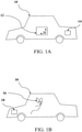
- Fig. 1 schematically shows two driving vehicles 10 equipped with systems for velocity estimation.
- Fig. 1A shows an example not claimed with a driving vehicle 10 comprising a built-in vehicle accelerometer 12 and a velocity estimation processing part 14.
- the accelerometer 12 is a three-axes accelerometer wherein the three axes of the accelerometer as depicted correspond substantially to the longitudinal, lateral and vertical axes of the vehicle.
- the according accelerometer signals from the accelerometer 12 correspond to longitudinal, lateral, and vertical acceleration of the vehicle, respectively.
- Each of the accelerometer axes may provide information about vehicle velocity.
- accelerometer signals of at least one of the axes may be used by the velocity estimation processing part 14 to determine a characteristic frequency in the accelerometer signals, e.g.
- the accelerometer signals indicative of the longitudinal acceleration axis of the vehicle may be used to perform a frequency spectrum analysis and to determine a characteristic frequency in the accelerometer signal spectrum and to estimate the velocity of the vehicle based on the determined characteristic frequency.
- Fig. 1B shows a driving vehicle 10 in the form of a car.
- the vehicle comprises a smartphone 16, held by a passenger, which comprises both an accelerometer and a velocity estimation processing part.
- the axes of the accelerometer may in general not coincide with the axes of the vehicle 10.
- the axes of the accelerometer may vary their orientation relative to the axes of the vehicle, e.g. when the passenger moves his or her hand.
- accelerometer signals from the smartphone accelerometer may be used to determine a characteristic frequency in the accelerometer signals, e.g. by performing a frequency spectrum analysis and determining the characteristic frequency in the accelerometer signal spectrum, and to estimate the velocity of the vehicle based on the determined characteristic frequency.
- the accelerometer signals originating from the accelerometer of smartphone 16 are indicative of an acceleration of vehicle 10.
- the object of the velocity estimation may be the object of the velocity estimation.
- smartphone 16 may be a stand-alone system for estimating vehicle velocities.
- the estimated velocities and/or accelerometer signals may be transmitted to the vehicle or its electronic control unit (ECU) 18.
- ECU electronice control unit
- the characteristic frequency may be determined by applying a model to the accelerometer signal to obtain an estimation output and by determining the characteristic frequency in the estimation output.
- Fig. 2 shows exemplary data.
- Fig. 2A shows an exemplary accelerometer signal spectrum 20, which consists of spectral amplitudes as a function of frequencies (in Hertz).
- the accelerometer signal spectrum 20 has been obtained by performing a frequency spectrum analysis of signals from a longitudinal accelerometer.
- the accelerometer signal spectrum 20 shows a series of peaks with local maxima of spectral amplitude.
- fundamental frequency peak 22 represents the peak corresponding to the fundamental frequency.
- the corresponding frequency is a fundamental frequency of the accelerometer signal spectrum 20.
- the fundamental frequency is approximately 13 Hz.
- the peak of the fundamental frequency is, in the present case, identical to the peak of the global maximum spectral amplitude.
- the fundamental frequency may in some examples, including the one of Fig. 2 , be the characteristic frequency to be determined and used for estimating the velocity of the vehicle. Additionally, other characteristic peaks such as harmonic frequency peak 24 may be used to determine a characteristic frequency. Harmonic frequency peak 24 represents the peak corresponding to a harmonic of the fundamental frequency, namely the second harmonic (wherein the second harmonic frequency equals three times the fundamental frequency) at approximately 39 Hz. In general, the determined characteristic frequency is proportional to the rotational velocity of the wheel. The characteristics of the peaks at fundamental frequency and at harmonic frequencies (overtones) may provide information to increase the reliability of estimated velocities.
- Fig. 2B shows a time series 26 of velocities (in km/h) as a function of time (in seconds). For each data point, i.e. for each velocity value at a given time, the value of the characteristic frequency has been determined. For each data point, based on the determined characteristic frequency, the velocity value has been estimated. For instance, at the time to (depicted in Fig. 2B at approximately 100 sec), the velocity is estimated based on Fig. 2A , namely the determined characteristic fundamental frequency of Fig. 2A . In particular, in the depicted exemplary data, the velocity is estimated by multiplying the determined frequency with a proportionality factor.
- the velocity time series may show artifacts in the form of spurious discontinuities. These may be due to a false determination of the characteristic frequency (e.g. harmonic peak 24 instead of fundamental harmonic peak 22 in Fig. 2A ) and may be eliminated by filtering based on the assumption that velocities typically do not change momentarily or by utilizing the relation between the harmonics.
- the characteristic frequency e.g. harmonic peak 24 instead of fundamental harmonic peak 22 in Fig. 2A
- Fig. 3 shows an accelerometer 34 and a system 30 to estimate a velocity of a vehicle comprising a velocity estimation processing part 36.
- the velocity estimation processing part 36 is configured to determine a characteristic frequency in accelerometer signals by performing a frequency spectrum analysis of accelerometer signals from accelerometer 34 to obtain an accelerometer signal spectrum, and to estimate the velocity of the vehicle based on the determined characteristic frequency.
- the accelerometer is external to the system.
- the system as such comprises the accelerometer.
- the system of Fig. 3 further comprises an optional location estimation processing part 38, which is configured to estimate a position of the vehicle.
- the location estimation processing part 38 may be used for navigation and/or sensor fusion, as will be detailed below. Estimated velocities may form a navigation aid, when combined with map information, as known from, e.g. EP 1 332 336 B1 .
- Map information may include spatially resolved information about roads, i.e. spaces accessible to the vehicle, and non-accessible spaces. With knowledge about the current position of the vehicle, in "real" space or on the map, and with information about the change of position, i.e. the velocity, the system may track the position on the map. This minimizes the error of dead reckoning by excluding non-accessible spaces. For instance, map information may be stored in system 30 or external thereto (e.g. on a memory device or on a remote server).
- the velocity estimation processing part 36 and location estimation processing part 38 are depicted as separate parts. They may however, in further cases, be combined into a single processing unit.
- Fig. 4 shows a flow chart of an exemplary method to estimate a velocity of the vehicle, here illustrated to comprise three steps.
- a frequency spectrum analysis of accelerometer signals is performed (step 42) to obtain an accelerometer signal spectrum, the accelerometer signals indicating an acceleration of the vehicle.
- a characteristic frequency is determined (step 44) in the accelerometer signal spectrum.
- the velocity of the vehicle is estimated (step 46) based on the determined characteristic frequency.
- a model may be applied (not shown) to obtain an estimation output, based on which the characteristic frequency may be determined.
- Fig. 5 schematically shows a flow chart of methods to estimate a velocity of a vehicle.
- Performing a frequency spectrum analysis (step 52) on accelerometer signals may be similar to step 42 of Fig. 4 .
- Determining a characteristic frequency (step 54) in the accelerometer signal spectrum may be similar to step 44 of Fig. 4 .
- velocity estimation (step 56) is based on both the determined characteristic frequency (from accelerometer signals) and a sensor signal, which is indicative of a vehicle property of the vehicle.
- this sensor fusion approach may make use of a sensor signal indicating a velocity (measured by a wheel speed sensor, or a radar sensor, or a GPS sensor).
- the effective wheel radius, linking wheel rotation frequency and absolute ground speed may be determined at high accuracy.
- An example sensor signal, which is indicative of velocity using a wheel speed sensor is described in WO 2005/005993 A1 .
- Sensor fusion designates the combination of multiple independent measurements of a common underlying quantity or value. It makes use of the fact, that each measurement will have its own error. However, between the multiple independent measurements, these errors are not related. For the independence of measurements, multiple sensors may be used. As described here, the common underlying quantity is vehicle velocity. Independent measurements by disparate sensors may be carried out on the basis of accelerometer signals and on the basis of wheel speed sensors, for instance. The objective of sensor fusion is to increase reliability on data and decrease uncertainty. With respect to velocity measurements, this approach is particularly advisable.
- Fig. 6 shows a flow chart of further methods to estimate a velocity of a vehicle. Steps 62, 64, and 66 may be similar to steps 42, 44, and 46 of Fig. 4 , respectively.
- the method depicted in Fig. 6 comprises estimating a position of the vehicle (step 61) and correcting and/or updating the estimated position (step 68) of the vehicle based on the estimated velocity. Step 61 of estimating the position is performed by means of the Global Positioning system, GPS. Step 68 of correcting and/or updating the position may be used for a dead reckoning or inertial navigation. For instance, GPS signals may be available intermittently to estimate the current location or position of the vehicle.
- the most recent GPS signal may be updated iteratively. Once a more recent GPS signal becomes available, this newly estimated position of the vehicle forms the basis for dead reckoning navigation.
- This combination of GPS and dead reckoning limits the drawback of errors cumulating in pure dead reckoning (the error of each velocity estimation adds to the positioning error) and reduces the dependence on quasi-continuous GPS signals.
- more sparsely sampling GPS signals may add to battery life of mobile GPS receivers.
- this method may take into account map information, as detailed above, with reference to Fig. 3 .
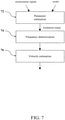
- Fig. 7 shows a flow chart of a method, not claimed, to estimate a velocity of the vehicle, here illustrated to comprise three steps.
- Parameter estimation is carried by applying a model to accelerometer signals (step 72), in order to obtain an estimation output, e.g. comprising a parameter such as a frequency or a parameter vector.
- the accelerometer signals indicate an acceleration of the vehicle.
- a characteristic frequency is determined (step 74) in the estimation output.
- the velocity of the vehicle is estimated (step 76) based on the determined characteristic frequency.
- the parameter estimation (step 72) considers a state-space model.
- the model noise w(k) and/or the measurement noise e(k) may for instance be Gaussian distributed with zero mean and finite covariance.
- the model applied in step 72 is given by imposing a sum of sinus functions with unknown amplitude, frequency and phase for the accelerometer signals (or each component thereof).
- the acceleration signals a(t) correspond to the measurement outcome y(k).
- a i amplitude
- fi frequency
- parametric estimation methods including but not limited to nonlinear least squares, Kalman filter, particle filter (sequential Monte Carlo) allow to find the characteristic frequency directly or indirectly from the estimated parameters, i.e. the estimation outcome.
- the step of parameter estimation yields a point estimate of x(k) from measurements y(k) (or a(t)).
- the model, including the measurement relation may relate the characteristic frequency to the observed measurements.
- the measurement relation uses the characteristic frequency as one parameter (as described above), which will be estimated and will be comprised by the estimation output.
- the characteristic frequency will not necessarily be comprised by the estimation output, but may be determined indirectly based on the estimation output.
- the velocity of the vehicle may be estimated, which may be carried out identically or similarly to the examples above, including the examples comprising a step of performing a frequency spectrum analysis.
Landscapes
- Physics & Mathematics (AREA)
- General Physics & Mathematics (AREA)
- Navigation (AREA)
- Control Of Driving Devices And Active Controlling Of Vehicle (AREA)
- Position Fixing By Use Of Radio Waves (AREA)
Description
- The present invention disclosure generally relates to the area of estimating a velocity of an object.
- Motion of vehicles, objects, persons and anything that moves or can be moved (in the following collectively referred to as object, unless otherwise indicated) is characterized by a variety of variables, among which velocity or speed is of particular interest.
- Known methods to estimate velocities may be grouped according to their underlying principles. Velocity estimation can be carried out using inertial signals (e.g. from accelerometers), measurements of the Doppler shift of GPS (Global Positioning System) signals and/or measurements by forward-looking radar sensors, similar to a radar gun.
- An object of the present invention is to provide solutions for the estimation or determination of a velocity of an object, for example a vehicle.
- The scope of the invention is defined by the claims. Any "embodiments" or "example" which is disclosed in the description but is not covered by the claims should be considered as presented for illustrative purpose only.
- In the following, the term "velocity" and "speed" are considered as synonyms, unless otherwise indicated.
- In the following, the term "object" refers to any object (e.g. mobile devices, mobile phones, portable computers, clothing, shoes, luggage, ...); vehicle (e.g. cars, lorries, trucks, motorbikes, bicycles, scooters, skateboards, ships, skis, aircrafts, ...), persons (human beings), animals, and any other thing that can move or be moved.
- In the following, the term "first object" indicates an object, the velocity of which is to be determined or, at least, to be estimated, respectively. The invention is directed to estimating a velocity of a wheeled vehicle.
- In the following, the term "second object" indicates an object which is movable together with that first object. The invention is directed to estimating a velocity of a wheeled vehicle.
- The second object is movable together with a first object. For example, a first object is a vehicle and a second object is an electronic device in the vehicle, wherein the electronic device can be moved with the vehicle.
- Generally, the invention makes use of accelerometer signals, which indicate an acceleration of a second object. The invention is directed to accelerometer signals which indicate an acceleration of a handheld portable electronic device.
- In any case, the accelerometer signals are used to (at least) estimate a velocity of the first object. Accelerometer signals may indicate an acceleration(s) of zero or different from zero. Methods, systems and computer program products are disclosed.
- Accelerometer signals may, for example, be measured and supplied by an accelerometer. The term "accelerometer" is to be understood to encompass any inertial sensor device or apparatus capable of measuring an acceleration. In particular, translational acceleration is measured. Example accelerometers include piezoelectric ones (with a mass attached a piezo sensor, wherein the acceleration of the mass translates into a force acting to deform the piezo, thereby creating an electric voltage) or micro-electro-mechanical systems (MEMS, with a suspended silicon structure acting as a spring and undergoing changes in electric capacitance or resistance upon acceleration).
- Preferably, accelerometer signals may indicate a longitudinal or horizontal acceleration of the second object, a lateral acceleration of the second object, or a vertical acceleration of the second object. For instance, a substantial alignment between the accelerometer axes and the first object and/or the second object axes may be obtained if an accelerometer built into the respective one(s) of the first object and/or the second object is used.
- Additionally, or alternatively, linear combinations of the above acceleration axes may be indicated by accelerometer signals. For the purpose of the present invention, the first object, the second object and accelerometer do not necessarily need to be fixed with respect to one another. For instance, for velocity estimation of a vehicle), accelerometer signals from an accelerometer built into a smartphone held by a passenger of the vehicle may be used.
- The term "velocity" is understood to encompass both absolute (scalar) values and vector-type values, which consist of an absolute value and a direction, and combinations thereof. Also, the term "velocity" encompasses both translational speed (e.g. expressed in m.p.h. or km/h) and rotational speed (e.g. expressed in radians per second) as well as combinations thereof. A "velocity" may be zero or different from zero.
- In general, a characteristic frequency is determined in the accelerometer signals. A frequency spectrum analysis is performed on the accelerometer signals to obtain an accelerometer signal spectrum. The term "frequency spectrum analysis" particularly refers to any method capable of exploring the induced harmonics, e.g. from a rotational device (axle, wheels, or similar periodic behavior in the surrounding of the measuring device), on the acceleration signal to infer the speed of the object. For example, the vibration properties may be indicative of an energy distribution in the system. One example to conduct such analysis is to apply frequency analysis. For instance, consistent with some examples, the frequency spectrum analysis may comprise non-parametric methods like a Fourier transformation or a Fast Fourier transformation (FFT).
- In other examples, not claimed, alternatively to the frequency spectrum analysis, a model may be applied to the accelerometer signals to obtain an estimation output. For instance, parametric methods like model identification and filtering may be applied. In particular, models may be applied in various signal processing schemes, like Kalman Filters, Sequential Monte-Carlo Filtering, System identification, etc.
- In general, a characteristic frequency in the accelerometer signals is determined. For instance, in the case of frequency spectrum analysis, the characteristic frequency may be determined in the accelerometer signal spectrum, wherein the characteristic frequency is a frequency of maximum spectral amplitude. Alternatively, in the case of model application, which is not claimed, the characteristic frequency may be determined in the estimation output. In particular, the estimation output may comprise a parameter or a parameter vector, which directly or indirectly corresponds to the characteristic frequency.
- In general, based on the determined characteristic frequency, the velocity of the first object is estimated. Estimating the velocity based on the determined characteristic frequency comprises multiplying the determined characteristic frequency with a proportionality factor.
- For instance, in the case of a wheeled vehicle, the proportionality factor may be determined on the basis of a wheel radius. In particular, from the accelerometer signal, a characteristic frequency may be determined, which can be related to the rotational frequency of the wheel due to a proportionality factor of 2∗pi∗R, wherein R is the wheel radius, or in the case of an axle the mean value of wheel radii.
- In some examples, the accelerometer signals may indicate accelerations of the second object in multiple dimensions. For instance, the accelerometer may be a three-axis accelerometer. The steps of determining a characteristic frequency and estimating the velocity of the first object may thus be carried out for each one of the three axes of the accelerometer.
- In some examples, the estimated velocity may be used for sensor fusion. Sensor fusion aims at an increase in reliability or a decrease in uncertainty by combining multiple sensor signals.
- For instance, in addition to accelerometer signals, at least one sensor signal indicative of a further object property of the first object and/or the second object may be used and form a further basis for estimating the velocity of the first object. A sensor signal indicative of a further object property may be indicative of any of the following: a wheel speed; a tire pressure; a location; a wheel acceleration; individual tire longitudinal stiffness; ambient and/or tire temperature; suspension pressure; wheel radius change; wheel vibration; wheel acceleration; suspension height information; suspension stiffness; operation of a suspension control system; yaw rate; speed of the first object and/or the second object; a steering wheel angle; a driving or movement condition; particularly a braking condition; operation of a braking system of the first object; brake pressure; operation of an active control device; engine torque of an engine of the first object; wheel slip; tractive force; engine speed of an engine; a gear shift being in progress.
- Consistent with some examples the estimated velocity may be used for dead reckoning or inertial navigation or localization. For instance, a position of the first object may be estimated and the estimated position may be updated and/or corrected based on the estimated velocity.
- In particular, the position of the first object may be estimated based on a satellite based localization/navigation system (e.g. GPS, GLONASS, Galileo, BeiDou, etc.), a radar system, or a wheel speed sensor. Further, in some examples, updating and/or correcting the estimated position may be further based on map information.
- In general, a system to estimate a velocity of a first object is disclosed, comprising a velocity estimation processing part configured to determine a characteristic frequency in accelerometer signals, wherein the accelerometer signals indicate an acceleration of a second object. The above observations in this regard apply here correspondingly.
- The acceleration may or may not be different from zero, i.e. the object may be accelerating or not. The velocity estimation processing part is further configured to estimate the velocity of the first object based on the determined characteristic frequency.
- For illustration purposes, the first object and the second object may correspond to a car and a smartphone, respectively.
- In the system, the velocity estimation processing part is further configured to perform a frequency spectrum analysis on the accelerometer signals to obtain an accelerometer signal spectrum and to determine the characteristic frequency in the accelerometer signal spectrum.
- In other examples of the system, not claimed, the velocity estimation processing part may be configured to apply a model to the accelerometer signals to obtain an estimation output and to determine the characteristic frequency in the estimation output. The observations made above with regard to the disclosed methods apply here correspondingly.
- Consistent with some examples of the system, the accelerometer signals originate from an accelerometer associated to a portable electronic device. For instance, the portable electronic device may be a phone, a smartphone, a watch, a training computer, a laptop, a tablet computer. The system comprises the accelerometer. In some examples, not claimed, the accelerometer may be external to the system. Accelerometer signals may be transmitted to the velocity estimation processing part in a variety of ways, including wireless connections (such as WLAN, Bluetooth, RFID, optical communication) or wired connections (such as bus systems, the Controller Area Network CAN).
- In some examples of the system, the estimated velocity may be used for sensor fusion. For instance, the velocity estimation processing part may be configured to further receive a sensor signal indicative of a further object property of the first object and/or the second object and to estimate the velocity of the first object based on the at least one sensor signal. A sensor signal indicative of a further objects property may be indicative of any of the following: a wheel speed; a tire pressure; a location; a wheel acceleration; individual tire longitudinal stiffness; ambient and/or tire temperature; suspension pressure; wheel radius change; wheel vibration; wheel acceleration; suspension height information; suspension stiffness; operation of a suspension control system; yaw rate; speed; a steering wheel angle; a driving or movement condition; particularly a braking condition; operation of a braking system; brake pressure; operation of an active control device; engine torque of an engine; wheel slip; tractive force; engine speed of an engine; a gear shift being in progress.
- Consistent with some examples, the system may comprise a location estimation part, configured to estimate a position of the first object and to update and/or correct the estimated position based on the estimated velocity. In particular, the location estimation processing part may be configured to update and/or correct the estimated position based on map information.
- The system comprises the portable electronic device.
- The following detailed description refers to the appended drawings, wherein:
- Fig. 1
- schematically shows driving vehicles comprising accelerometers and velocity estimation processing parts.
- Fig. 2
- schematically shows an exemplary accelerometer signal spectrum and a time series of exemplary velocities estimated based on determined characteristic frequencies in accelerometer signal spectra.
- Fig. 3
- schematically shows an example of a system to estimate a velocity of a vehicle.
- Fig. 4
- schematically shows a flow diagram of an example of a method of estimating a velocity of a vehicle.
- Fig. 5
- schematically shows a flow chart of a further example of a method according to the present invention.
- Fig. 6
- shows a further flow chart of a further example of a method according to the present invention.
- Fig. 7
- shows a further flow chart of an example which does not correspond to the claimed invention.
- The following description of the drawings refers to vehicles as not limiting examples of first objects.
-
Fig. 1 schematically shows two drivingvehicles 10 equipped with systems for velocity estimation. - In particular,
Fig. 1A shows an example not claimed with a drivingvehicle 10 comprising a built-invehicle accelerometer 12 and a velocityestimation processing part 14. Theaccelerometer 12 is a three-axes accelerometer wherein the three axes of the accelerometer as depicted correspond substantially to the longitudinal, lateral and vertical axes of the vehicle. As a result, the according accelerometer signals from theaccelerometer 12 correspond to longitudinal, lateral, and vertical acceleration of the vehicle, respectively. Each of the accelerometer axes may provide information about vehicle velocity. For velocity estimation, accelerometer signals of at least one of the axes may be used by the velocityestimation processing part 14 to determine a characteristic frequency in the accelerometer signals, e.g. by performing a frequency spectrum analysis to obtain at least one accelerometer signal spectrum and by determining the characteristic frequency in the accelerometer signal spectrum. For instance, the accelerometer signals indicative of the longitudinal acceleration axis of the vehicle may be used to perform a frequency spectrum analysis and to determine a characteristic frequency in the accelerometer signal spectrum and to estimate the velocity of the vehicle based on the determined characteristic frequency. -
Fig. 1B shows a drivingvehicle 10 in the form of a car. The vehicle comprises asmartphone 16, held by a passenger, which comprises both an accelerometer and a velocity estimation processing part. The axes of the accelerometer may in general not coincide with the axes of thevehicle 10. The axes of the accelerometer may vary their orientation relative to the axes of the vehicle, e.g. when the passenger moves his or her hand. Nevertheless, accelerometer signals from the smartphone accelerometer may be used to determine a characteristic frequency in the accelerometer signals, e.g. by performing a frequency spectrum analysis and determining the characteristic frequency in the accelerometer signal spectrum, and to estimate the velocity of the vehicle based on the determined characteristic frequency. The accelerometer signals originating from the accelerometer ofsmartphone 16 are indicative of an acceleration ofvehicle 10. Alternatively to thecars 10 ofFig 1 , other vehicle may be the object of the velocity estimation. As detailed above and described with reference toFig. 1B ,smartphone 16 may be a stand-alone system for estimating vehicle velocities. However, the estimated velocities and/or accelerometer signals may be transmitted to the vehicle or its electronic control unit (ECU) 18. Alternatively to determining a characteristic frequency by performing a frequency spectrum, in examples not claimed, the characteristic frequency may be determined by applying a model to the accelerometer signal to obtain an estimation output and by determining the characteristic frequency in the estimation output. -
Fig. 2 shows exemplary data. In particular,Fig. 2A shows an exemplaryaccelerometer signal spectrum 20, which consists of spectral amplitudes as a function of frequencies (in Hertz). Theaccelerometer signal spectrum 20 has been obtained by performing a frequency spectrum analysis of signals from a longitudinal accelerometer. Theaccelerometer signal spectrum 20 shows a series of peaks with local maxima of spectral amplitude. In particular,fundamental frequency peak 22 represents the peak corresponding to the fundamental frequency. The corresponding frequency is a fundamental frequency of theaccelerometer signal spectrum 20. In the exemplary data depicted inFig. 2A , the fundamental frequency is approximately 13 Hz. Moreover, the peak of the fundamental frequency is, in the present case, identical to the peak of the global maximum spectral amplitude. The fundamental frequency may in some examples, including the one ofFig. 2 , be the characteristic frequency to be determined and used for estimating the velocity of the vehicle. Additionally, other characteristic peaks such asharmonic frequency peak 24 may be used to determine a characteristic frequency.Harmonic frequency peak 24 represents the peak corresponding to a harmonic of the fundamental frequency, namely the second harmonic (wherein the second harmonic frequency equals three times the fundamental frequency) at approximately 39 Hz. In general, the determined characteristic frequency is proportional to the rotational velocity of the wheel. The characteristics of the peaks at fundamental frequency and at harmonic frequencies (overtones) may provide information to increase the reliability of estimated velocities. -
Fig. 2B shows atime series 26 of velocities (in km/h) as a function of time (in seconds). For each data point, i.e. for each velocity value at a given time, the value of the characteristic frequency has been determined. For each data point, based on the determined characteristic frequency, the velocity value has been estimated. For instance, at the time to (depicted inFig. 2B at approximately 100 sec), the velocity is estimated based onFig. 2A , namely the determined characteristic fundamental frequency ofFig. 2A . In particular, in the depicted exemplary data, the velocity is estimated by multiplying the determined frequency with a proportionality factor. - In some cases, the velocity time series may show artifacts in the form of spurious discontinuities. These may be due to a false determination of the characteristic frequency (e.g.
harmonic peak 24 instead of fundamentalharmonic peak 22 inFig. 2A ) and may be eliminated by filtering based on the assumption that velocities typically do not change momentarily or by utilizing the relation between the harmonics. -
Fig. 3 shows anaccelerometer 34 and asystem 30 to estimate a velocity of a vehicle comprising a velocityestimation processing part 36. The velocityestimation processing part 36 is configured to determine a characteristic frequency in accelerometer signals by performing a frequency spectrum analysis of accelerometer signals fromaccelerometer 34 to obtain an accelerometer signal spectrum, and to estimate the velocity of the vehicle based on the determined characteristic frequency. - In
Fig. 3 , in an example not claimed, the accelerometer is external to the system. However, in the invention, the system as such comprises the accelerometer. The system ofFig. 3 further comprises an optional locationestimation processing part 38, which is configured to estimate a position of the vehicle. The locationestimation processing part 38 may be used for navigation and/or sensor fusion, as will be detailed below. Estimated velocities may form a navigation aid, when combined with map information, as known from, e.g.EP 1 332 336 B1 . - Map information may include spatially resolved information about roads, i.e. spaces accessible to the vehicle, and non-accessible spaces. With knowledge about the current position of the vehicle, in "real" space or on the map, and with information about the change of position, i.e. the velocity, the system may track the position on the map. This minimizes the error of dead reckoning by excluding non-accessible spaces. For instance, map information may be stored in
system 30 or external thereto (e.g. on a memory device or on a remote server). - The velocity
estimation processing part 36 and locationestimation processing part 38 are depicted as separate parts. They may however, in further cases, be combined into a single processing unit. -
Fig. 4 shows a flow chart of an exemplary method to estimate a velocity of the vehicle, here illustrated to comprise three steps. - A frequency spectrum analysis of accelerometer signals is performed (step 42) to obtain an accelerometer signal spectrum, the accelerometer signals indicating an acceleration of the vehicle. A characteristic frequency is determined (step 44) in the accelerometer signal spectrum. The velocity of the vehicle is estimated (step 46) based on the determined characteristic frequency. Alternatively to the frequency spectrum analysis (step 42), in examples not claimed, a model may be applied (not shown) to obtain an estimation output, based on which the characteristic frequency may be determined.
-
Fig. 5 schematically shows a flow chart of methods to estimate a velocity of a vehicle. Performing a frequency spectrum analysis (step 52) on accelerometer signals may be similar to step 42 ofFig. 4 . Determining a characteristic frequency (step 54) in the accelerometer signal spectrum may be similar to step 44 ofFig. 4 . In the cases ofFig. 5 , velocity estimation (step 56) is based on both the determined characteristic frequency (from accelerometer signals) and a sensor signal, which is indicative of a vehicle property of the vehicle. For instance, this sensor fusion approach may make use of a sensor signal indicating a velocity (measured by a wheel speed sensor, or a radar sensor, or a GPS sensor). In particular, the effective wheel radius, linking wheel rotation frequency and absolute ground speed, may be determined at high accuracy. An example sensor signal, which is indicative of velocity using a wheel speed sensor is described inWO 2005/005993 A1 . - Sensor fusion designates the combination of multiple independent measurements of a common underlying quantity or value. It makes use of the fact, that each measurement will have its own error. However, between the multiple independent measurements, these errors are not related. For the independence of measurements, multiple sensors may be used. As described here, the common underlying quantity is vehicle velocity. Independent measurements by disparate sensors may be carried out on the basis of accelerometer signals and on the basis of wheel speed sensors, for instance. The objective of sensor fusion is to increase reliability on data and decrease uncertainty. With respect to velocity measurements, this approach is particularly advisable.
-
Fig. 6 shows a flow chart of further methods to estimate a velocity of a vehicle.Steps steps Fig. 4 , respectively. In addition to these steps, the method depicted inFig. 6 comprises estimating a position of the vehicle (step 61) and correcting and/or updating the estimated position (step 68) of the vehicle based on the estimated velocity.Step 61 of estimating the position is performed by means of the Global Positioning system, GPS.Step 68 of correcting and/or updating the position may be used for a dead reckoning or inertial navigation. For instance, GPS signals may be available intermittently to estimate the current location or position of the vehicle. During non-availability of up-to-date GPS signals (for any of a variety of reasons, including bad reception), the most recent GPS signal may be updated iteratively. Once a more recent GPS signal becomes available, this newly estimated position of the vehicle forms the basis for dead reckoning navigation. This combination of GPS and dead reckoning limits the drawback of errors cumulating in pure dead reckoning (the error of each velocity estimation adds to the positioning error) and reduces the dependence on quasi-continuous GPS signals. In addition, more sparsely sampling GPS signals may add to battery life of mobile GPS receivers. In addition to estimating the position, this method may take into account map information, as detailed above, with reference toFig. 3 . -
Fig. 7 shows a flow chart of a method, not claimed, to estimate a velocity of the vehicle, here illustrated to comprise three steps. Parameter estimation is carried by applying a model to accelerometer signals (step 72), in order to obtain an estimation output, e.g. comprising a parameter such as a frequency or a parameter vector. The accelerometer signals indicate an acceleration of the vehicle. A characteristic frequency is determined (step 74) in the estimation output. The velocity of the vehicle is estimated (step 76) based on the determined characteristic frequency. - The parameter estimation (step 72) considers a state-space model. The model may be defined in discrete time t=k∗T, wherein T is a unit time, by a transition relation and a measurement relation.
- For instance, the following transition relation may define how the estimation output changes from one point in time (k) to the next point in time (k+1):

- For instance, the following measurement relation defines how the estimation output influences the measurement outcome:

- According to
Fig. 7 , the model applied instep 72 is given by imposing a sum of sinus functions with unknown amplitude, frequency and phase for the accelerometer signals (or each component thereof). The acceleration signals a(t) correspond to the measurement outcome y(k). Hence the acceleration signals a(t) can for example be written as
- By imposing these exemplary model constraints, parametric estimation methods, including but not limited to nonlinear least squares, Kalman filter, particle filter (sequential Monte Carlo) allow to find the characteristic frequency directly or indirectly from the estimated parameters, i.e. the estimation outcome.
- The step of parameter estimation yields a point estimate of x(k) from measurements y(k) (or a(t)). For instance, the dynamic function F(x) can be, for example

- According to
Fig. 7 , the measurement relation uses the characteristic frequency as one parameter (as described above), which will be estimated and will be comprised by the estimation output. In other examples, the characteristic frequency will not necessarily be comprised by the estimation output, but may be determined indirectly based on the estimation output. - Based on the determined characteristic frequency, the velocity of the vehicle may be estimated, which may be carried out identically or similarly to the examples above, including the examples comprising a step of performing a frequency spectrum analysis.
Claims (6)
- Method of estimating a velocity of a wheeled vehicle (10), wherein the vehicle is a car or a truck, the method comprising:- determining a characteristic frequency in accelerometer signals from an accelerometer (34) of a handheld portable electronic device (16), which indicate a translational acceleration of the handheld portable electronic device (16), wherein the characteristic frequency is proportional to a rotational frequency of a wheel of the wheeled vehicle, and- estimating the velocity of the vehicle based on the determined characteristic frequency, wherein estimating comprises multiplying the determined characteristic frequency with a proportionality factor,wherein the handheld portable electronic device (16) is in the vehicle and movable together with said vehicle,
wherein the determining comprises:- performing a frequency spectrum analysis of accelerometer signals to obtain an accelerometer signal spectrum (20), and- determining a frequency of maximal spectral amplitude as a fundamental frequency in the accelerometer signal spectrum (20), proportional to the rotational frequency of the wheel. - Method according to the preceding claim, wherein determining the characteristic frequency is performed on at least one of the following:- accelerometer signals indicating a longitudinal or horizontal acceleration;- accelerometer signals indicating a lateral acceleration;- accelerometer signals indicating a vertical acceleration.
- Method according to one of the preceding claims, further comprising:- estimating a position of the vehicle and/or the handheld portable electronic device (16), and- updating and/or correcting the estimated position of the vehicle and/or the handheld portable electronic device (16) based on the estimated velocity.
- System (30) to estimate a velocity of a wheeled vehicle (10), wherein the vehicle is a car or a truck, the system comprising a handheld portable electronic device (16) with an accelerometer (34) and a velocity estimation processing part (36) configured to- determine a characteristic frequency in accelerometer signals from the accelerometer (34), which indicate a translational acceleration of the handheld portable electronic device (16), wherein the characteristic frequency is proportional to a rotational frequency of a wheel of the wheeled vehicle, and- estimate the velocity of the vehicle based on the determined characteristic frequency, wherein estimating comprises multiplying the determined characteristic frequency with a proportionality factor,wherein the handheld portable electronic device (16) is adapted to be in the vehicle and movable together with said vehicle,
wherein the velocity estimation processing part is further configured to- perform a frequency spectrum analysis of the accelerometer signals to obtain an accelerometer signal spectrum (20), and- determine a frequency of maximal spectral amplitude as a fundamental frequency in the accelerometer signal spectrum (20), proportional to the rotational frequency of the wheel. - System according to claim 4, further comprising a comprising a location estimation processing part configured to- estimate a position of the vehicle and/or the handheld portable electronic device (16), and- update and/or correct the estimated position of the vehicle and/or the handheld portable electronic device (16) based on the estimated velocity.
- Computer program product including program code configured to cause the system according to claims 4 or 5 to carry out the steps of one of the claims 1 to 3.
Applications Claiming Priority (1)
| Application Number | Priority Date | Filing Date | Title |
|---|---|---|---|
| PCT/EP2015/001648 WO2017025109A1 (en) | 2015-08-10 | 2015-08-10 | Velocity estimation |
Publications (2)
| Publication Number | Publication Date |
|---|---|
| EP3335051A1 EP3335051A1 (en) | 2018-06-20 |
| EP3335051B1 true EP3335051B1 (en) | 2022-03-23 |
Family
ID=53836043
Family Applications (1)
| Application Number | Title | Priority Date | Filing Date |
|---|---|---|---|
| EP15749988.0A Not-in-force EP3335051B1 (en) | 2015-08-10 | 2015-08-10 | Velocity estimation |
Country Status (6)
| Country | Link |
|---|---|
| US (1) | US10969401B2 (en) |
| EP (1) | EP3335051B1 (en) |
| JP (1) | JP6877403B2 (en) |
| KR (1) | KR20180039094A (en) |
| CN (1) | CN108139422B (en) |
| WO (1) | WO2017025109A1 (en) |
Families Citing this family (10)
| Publication number | Priority date | Publication date | Assignee | Title |
|---|---|---|---|---|
| CN108137074B (en) * | 2015-09-04 | 2021-12-03 | 看门人系统公司 | Motion estimation for wheeled vehicles |
| US9395384B1 (en) * | 2015-10-07 | 2016-07-19 | State Farm Mutual Automobile Insurance Company | Systems and methods for estimating vehicle speed and hence driving behavior using accelerometer data during periods of intermittent GPS |
| EP4509806A3 (en) | 2017-03-08 | 2025-05-14 | Gatekeeper Systems, Inc. | Navigation systems for wheeled carts |
| EP3611541B1 (en) * | 2018-08-16 | 2024-07-03 | Aptiv Technologies AG | Method of determining an uncertainty estimate of an estimated velocity |
| DE102018221713A1 (en) * | 2018-12-13 | 2020-06-18 | Robert Bosch Gmbh | Method and device for determining a rotational frequency of a wheel |
| CN110514861B (en) * | 2019-08-16 | 2020-07-28 | 西安交通大学 | A high-speed rail speed estimation method using amplitude spectrum autocorrelation |
| CN114167471A (en) | 2020-09-11 | 2022-03-11 | 意法半导体股份有限公司 | Method for motion estimation in a vehicle, corresponding device and computer program product |
| DE102022200305A1 (en) * | 2022-01-13 | 2023-07-13 | Zf Friedrichshafen Ag | Method and device for determining longitudinal tire stiffness |
| JP7641247B2 (en) | 2022-03-02 | 2025-03-06 | 日立建機株式会社 | Machine performance diagnostic equipment |
| GB2618843A (en) * | 2022-05-20 | 2023-11-22 | Appy Risk Tech Limited | A method and system for generating a vehicle mileage |
Citations (2)
| Publication number | Priority date | Publication date | Assignee | Title |
|---|---|---|---|---|
| JP3207570B2 (en) * | 1992-12-25 | 2001-09-10 | 明星電気株式会社 | Vehicle speed estimation method and vehicle speed detection device |
| EP1788358A1 (en) * | 2005-11-17 | 2007-05-23 | Efkon Mobility GmbH | Method and arrangement for vehicle-internal determination of the distance covered by a vehicle |
Family Cites Families (25)
| Publication number | Priority date | Publication date | Assignee | Title |
|---|---|---|---|---|
| DE3812904A1 (en) * | 1988-03-09 | 1989-09-21 | Lucas Ind Plc | BLOCK-PROTECTED BRAKE SYSTEM WITH MONITORED SPEED SENSOR AND METHOD FOR MEASURING THE SPEED IN SUCH A BRAKE SYSTEM |
| JP3165314B2 (en) * | 1994-01-28 | 2001-05-14 | 株式会社東芝 | Vehicle speed calculation device and vehicle mileage calculation device using the same |
| US5636146A (en) * | 1994-11-21 | 1997-06-03 | Phatrat Technology, Inc. | Apparatus and methods for determining loft time and speed |
| CN1216300C (en) * | 2001-11-06 | 2005-08-24 | 深圳麦士威科技有限公司 | Detector for detecting moving speed and safety interval of vehicls |
| US7133801B2 (en) * | 2002-06-07 | 2006-11-07 | Exxon Mobil Research And Engineering Company | System and methodology for vibration analysis and condition monitoring |
| JP2004085511A (en) | 2002-08-29 | 2004-03-18 | Hitachi Ltd | Method and system for estimating moving speed and position of moving object and navigation system |
| US6694260B1 (en) * | 2003-05-09 | 2004-02-17 | Deere & Company | Inertial augmentation for GPS navigation on ground vehicles |
| US6816804B1 (en) | 2003-06-04 | 2004-11-09 | Visteon Global Technologies, Inc. | System and method for estimating velocity using reliability indexed sensor fusion |
| ATE381022T1 (en) * | 2003-06-18 | 2007-12-15 | Nxp Bv | CIRCUIT ARRANGEMENT AND METHOD FOR OBTAINING AN OUTPUT SIGNAL, AND SPEED MEASUREMENT DEVICE EQUIPPED WITH SUCH A CIRCUIT ARRANGEMENT |
| FR2872905B1 (en) * | 2004-07-06 | 2006-09-22 | Snr Roulements Sa | METHOD FOR DETERMINING A SPACE HARMONIC ANALYSIS CONDITION OF SPEED |
| JP4516380B2 (en) | 2004-08-20 | 2010-08-04 | 本田技研工業株式会社 | Speed indicator for electric motorcycles |
| JP2006194372A (en) | 2005-01-14 | 2006-07-27 | Hitachi Metals Techno Ltd | Vibration control hydraulic damper |
| DE102006020471B4 (en) * | 2006-04-28 | 2008-01-03 | Trajet Gmbh | Measuring device for vehicle data, in particular for the speed of a vehicle running on wheels |
| JP2009145214A (en) * | 2007-12-14 | 2009-07-02 | Funai Electric Co Ltd | Navigation device |
| US8843275B2 (en) * | 2008-06-18 | 2014-09-23 | Trw Automotive U.S. Llc | Method and apparatus for determining a vehicle pitch-over condition |
| CN101634659A (en) * | 2008-07-23 | 2010-01-27 | 中国科学院自动化研究所 | Rotating speed or speed measuring device and detection method based on accelerometer |
| WO2010029484A1 (en) * | 2008-09-09 | 2010-03-18 | Philips Intellectual Property & Standards Gmbh | Velocity determination apparatus |
| JP5349980B2 (en) * | 2009-01-09 | 2013-11-20 | 株式会社小野測器 | Signal processing apparatus, signal processing apparatus control method, and signal processing apparatus control program |
| JP5617324B2 (en) * | 2010-04-21 | 2014-11-05 | 日本電気株式会社 | Speed estimation method, speed estimation apparatus, speed estimation system, and control program for speed estimation apparatus |
| ES2417323T3 (en) * | 2010-10-15 | 2013-08-07 | Ar Innovation Ag | Sensor apparatus and method to determine the pedaling rate and the speed of a bicycle |
| JP2012160115A (en) | 2011-02-02 | 2012-08-23 | Denso Corp | Travel information recording device |
| US8903668B2 (en) * | 2011-04-11 | 2014-12-02 | GM Global Technology Operations LLC | Alternator speed estimation using spectrum analysis |
| JP2013003048A (en) * | 2011-06-20 | 2013-01-07 | Sony Corp | Route search apparatus, route search method, and program |
| US10451437B2 (en) * | 2012-05-21 | 2019-10-22 | Amer Sports Digital Services Oy | Method for determining a measurable target variable and corresponding system |
| CN103323615B (en) | 2013-06-05 | 2015-08-12 | 中国科学院计算技术研究所 | A kind of mobile terminal and method being calculated walking speed by acceleration transducer |
-
2015
- 2015-08-10 US US15/751,839 patent/US10969401B2/en active Active
- 2015-08-10 CN CN201580082432.4A patent/CN108139422B/en not_active Expired - Fee Related
- 2015-08-10 WO PCT/EP2015/001648 patent/WO2017025109A1/en not_active Ceased
- 2015-08-10 KR KR1020187006111A patent/KR20180039094A/en not_active Ceased
- 2015-08-10 JP JP2018506956A patent/JP6877403B2/en active Active
- 2015-08-10 EP EP15749988.0A patent/EP3335051B1/en not_active Not-in-force
Patent Citations (2)
| Publication number | Priority date | Publication date | Assignee | Title |
|---|---|---|---|---|
| JP3207570B2 (en) * | 1992-12-25 | 2001-09-10 | 明星電気株式会社 | Vehicle speed estimation method and vehicle speed detection device |
| EP1788358A1 (en) * | 2005-11-17 | 2007-05-23 | Efkon Mobility GmbH | Method and arrangement for vehicle-internal determination of the distance covered by a vehicle |
Also Published As
| Publication number | Publication date |
|---|---|
| WO2017025109A1 (en) | 2017-02-16 |
| EP3335051A1 (en) | 2018-06-20 |
| US10969401B2 (en) | 2021-04-06 |
| JP2018523131A (en) | 2018-08-16 |
| CN108139422A (en) | 2018-06-08 |
| JP6877403B2 (en) | 2021-05-26 |
| CN108139422B (en) | 2021-09-21 |
| KR20180039094A (en) | 2018-04-17 |
| US20180231577A1 (en) | 2018-08-16 |
Similar Documents
| Publication | Publication Date | Title |
|---|---|---|
| US10969401B2 (en) | Velocity estimation | |
| JP7036080B2 (en) | Inertial navigation system | |
| Collin | MEMS IMU carouseling for ground vehicles | |
| Bevly et al. | Integrating INS sensors with GPS measurements for continuous estimation of vehicle sideslip, roll, and tire cornering stiffness | |
| Leung et al. | Road vehicle state estimation using low-cost GPS/INS | |
| Barrios et al. | Trajectory estimations using smartphones | |
| Oh et al. | Vehicle velocity observer design using 6-D IMU and multiple-observer approach | |
| CN105783921B (en) | A kind of method and device correcting automobile attitude data | |
| JP2015513131A (en) | Apparatus, system and method for calculating risk index for driving behavior | |
| US20110066376A1 (en) | Velocity calculating device, velocity calculating method, and navigation device | |
| CN113734180A (en) | Method and apparatus for determining vehicle speed | |
| EP3018030B1 (en) | Device for the detection of the attitude of motor vehicles | |
| EP4071739A1 (en) | Information processing device, control method, program, and storage medium | |
| CN111504584B (en) | Vibration evaluation method, device and system of sensor support and movable equipment | |
| JP2021018112A (en) | Self position estimation device | |
| JP7053087B1 (en) | Mobile behavior information acquisition method, mobile behavior information acquisition device and program | |
| JP5219547B2 (en) | Car navigation system and navigation method | |
| JP6154951B1 (en) | Velocity measuring device, position measuring device, velocity measuring method and program | |
| CN105606093A (en) | Inertial navigation method and device based on real-time gravity compensation | |
| Masino et al. | Development of a highly accurate and low cost measurement device for Field Operational Tests | |
| Mori et al. | Robust vehicle state estimation from urban driving to the limits of handling | |
| JP2023160540A (en) | Location estimation device, location estimation method, and location estimation program | |
| Jo et al. | Distributed vehicle state estimation system using information fusion of GPS and in-vehicle sensors for vehicle localization | |
| Farroni et al. | A comparison among different methods to estimate vehicle sideslip angle | |
| JP2012163509A (en) | Dead reckoning navigation device for vehicle, dead reckoning navigation method for vehicle and program for dead reckoning navigation method for vehicle |
Legal Events
| Date | Code | Title | Description |
|---|---|---|---|
| STAA | Information on the status of an ep patent application or granted ep patent |
Free format text: STATUS: THE INTERNATIONAL PUBLICATION HAS BEEN MADE |
|
| PUAI | Public reference made under article 153(3) epc to a published international application that has entered the european phase |
Free format text: ORIGINAL CODE: 0009012 |
|
| STAA | Information on the status of an ep patent application or granted ep patent |
Free format text: STATUS: REQUEST FOR EXAMINATION WAS MADE |
|
| 17P | Request for examination filed |
Effective date: 20180212 |
|
| AK | Designated contracting states |
Kind code of ref document: A1 Designated state(s): AL AT BE BG CH CY CZ DE DK EE ES FI FR GB GR HR HU IE IS IT LI LT LU LV MC MK MT NL NO PL PT RO RS SE SI SK SM TR |
|
| AX | Request for extension of the european patent |
Extension state: BA ME |
|
| DAV | Request for validation of the european patent (deleted) | ||
| DAX | Request for extension of the european patent (deleted) | ||
| STAA | Information on the status of an ep patent application or granted ep patent |
Free format text: STATUS: EXAMINATION IS IN PROGRESS |
|
| 17Q | First examination report despatched |
Effective date: 20191008 |
|
| GRAP | Despatch of communication of intention to grant a patent |
Free format text: ORIGINAL CODE: EPIDOSNIGR1 |
|
| STAA | Information on the status of an ep patent application or granted ep patent |
Free format text: STATUS: GRANT OF PATENT IS INTENDED |
|
| INTG | Intention to grant announced |
Effective date: 20211004 |
|
| GRAS | Grant fee paid |
Free format text: ORIGINAL CODE: EPIDOSNIGR3 |
|
| GRAA | (expected) grant |
Free format text: ORIGINAL CODE: 0009210 |
|
| STAA | Information on the status of an ep patent application or granted ep patent |
Free format text: STATUS: THE PATENT HAS BEEN GRANTED |
|
| AK | Designated contracting states |
Kind code of ref document: B1 Designated state(s): AL AT BE BG CH CY CZ DE DK EE ES FI FR GB GR HR HU IE IS IT LI LT LU LV MC MK MT NL NO PL PT RO RS SE SI SK SM TR |
|
| REG | Reference to a national code |
Ref country code: GB Ref legal event code: FG4D |
|
| REG | Reference to a national code |
Ref country code: CH Ref legal event code: EP |
|
| REG | Reference to a national code |
Ref country code: IE Ref legal event code: FG4D |
|
| REG | Reference to a national code |
Ref country code: DE Ref legal event code: R096 Ref document number: 602015077715 Country of ref document: DE |
|
| REG | Reference to a national code |
Ref country code: AT Ref legal event code: REF Ref document number: 1477791 Country of ref document: AT Kind code of ref document: T Effective date: 20220415 |
|
| REG | Reference to a national code |
Ref country code: LT Ref legal event code: MG9D |
|
| REG | Reference to a national code |
Ref country code: NL Ref legal event code: MP Effective date: 20220323 |
|
| PG25 | Lapsed in a contracting state [announced via postgrant information from national office to epo] |
Ref country code: SE Free format text: LAPSE BECAUSE OF FAILURE TO SUBMIT A TRANSLATION OF THE DESCRIPTION OR TO PAY THE FEE WITHIN THE PRESCRIBED TIME-LIMIT Effective date: 20220323 Ref country code: RS Free format text: LAPSE BECAUSE OF FAILURE TO SUBMIT A TRANSLATION OF THE DESCRIPTION OR TO PAY THE FEE WITHIN THE PRESCRIBED TIME-LIMIT Effective date: 20220323 Ref country code: NO Free format text: LAPSE BECAUSE OF FAILURE TO SUBMIT A TRANSLATION OF THE DESCRIPTION OR TO PAY THE FEE WITHIN THE PRESCRIBED TIME-LIMIT Effective date: 20220623 Ref country code: LT Free format text: LAPSE BECAUSE OF FAILURE TO SUBMIT A TRANSLATION OF THE DESCRIPTION OR TO PAY THE FEE WITHIN THE PRESCRIBED TIME-LIMIT Effective date: 20220323 Ref country code: HR Free format text: LAPSE BECAUSE OF FAILURE TO SUBMIT A TRANSLATION OF THE DESCRIPTION OR TO PAY THE FEE WITHIN THE PRESCRIBED TIME-LIMIT Effective date: 20220323 Ref country code: BG Free format text: LAPSE BECAUSE OF FAILURE TO SUBMIT A TRANSLATION OF THE DESCRIPTION OR TO PAY THE FEE WITHIN THE PRESCRIBED TIME-LIMIT Effective date: 20220623 |
|
| REG | Reference to a national code |
Ref country code: AT Ref legal event code: MK05 Ref document number: 1477791 Country of ref document: AT Kind code of ref document: T Effective date: 20220323 |
|
| PG25 | Lapsed in a contracting state [announced via postgrant information from national office to epo] |
Ref country code: LV Free format text: LAPSE BECAUSE OF FAILURE TO SUBMIT A TRANSLATION OF THE DESCRIPTION OR TO PAY THE FEE WITHIN THE PRESCRIBED TIME-LIMIT Effective date: 20220323 Ref country code: GR Free format text: LAPSE BECAUSE OF FAILURE TO SUBMIT A TRANSLATION OF THE DESCRIPTION OR TO PAY THE FEE WITHIN THE PRESCRIBED TIME-LIMIT Effective date: 20220624 Ref country code: FI Free format text: LAPSE BECAUSE OF FAILURE TO SUBMIT A TRANSLATION OF THE DESCRIPTION OR TO PAY THE FEE WITHIN THE PRESCRIBED TIME-LIMIT Effective date: 20220323 |
|
| PG25 | Lapsed in a contracting state [announced via postgrant information from national office to epo] |
Ref country code: NL Free format text: LAPSE BECAUSE OF FAILURE TO SUBMIT A TRANSLATION OF THE DESCRIPTION OR TO PAY THE FEE WITHIN THE PRESCRIBED TIME-LIMIT Effective date: 20220323 |
|
| PG25 | Lapsed in a contracting state [announced via postgrant information from national office to epo] |
Ref country code: SM Free format text: LAPSE BECAUSE OF FAILURE TO SUBMIT A TRANSLATION OF THE DESCRIPTION OR TO PAY THE FEE WITHIN THE PRESCRIBED TIME-LIMIT Effective date: 20220323 Ref country code: SK Free format text: LAPSE BECAUSE OF FAILURE TO SUBMIT A TRANSLATION OF THE DESCRIPTION OR TO PAY THE FEE WITHIN THE PRESCRIBED TIME-LIMIT Effective date: 20220323 Ref country code: RO Free format text: LAPSE BECAUSE OF FAILURE TO SUBMIT A TRANSLATION OF THE DESCRIPTION OR TO PAY THE FEE WITHIN THE PRESCRIBED TIME-LIMIT Effective date: 20220323 Ref country code: PT Free format text: LAPSE BECAUSE OF FAILURE TO SUBMIT A TRANSLATION OF THE DESCRIPTION OR TO PAY THE FEE WITHIN THE PRESCRIBED TIME-LIMIT Effective date: 20220725 Ref country code: ES Free format text: LAPSE BECAUSE OF FAILURE TO SUBMIT A TRANSLATION OF THE DESCRIPTION OR TO PAY THE FEE WITHIN THE PRESCRIBED TIME-LIMIT Effective date: 20220323 Ref country code: EE Free format text: LAPSE BECAUSE OF FAILURE TO SUBMIT A TRANSLATION OF THE DESCRIPTION OR TO PAY THE FEE WITHIN THE PRESCRIBED TIME-LIMIT Effective date: 20220323 Ref country code: CZ Free format text: LAPSE BECAUSE OF FAILURE TO SUBMIT A TRANSLATION OF THE DESCRIPTION OR TO PAY THE FEE WITHIN THE PRESCRIBED TIME-LIMIT Effective date: 20220323 Ref country code: AT Free format text: LAPSE BECAUSE OF FAILURE TO SUBMIT A TRANSLATION OF THE DESCRIPTION OR TO PAY THE FEE WITHIN THE PRESCRIBED TIME-LIMIT Effective date: 20220323 |
|
| PG25 | Lapsed in a contracting state [announced via postgrant information from national office to epo] |
Ref country code: PL Free format text: LAPSE BECAUSE OF FAILURE TO SUBMIT A TRANSLATION OF THE DESCRIPTION OR TO PAY THE FEE WITHIN THE PRESCRIBED TIME-LIMIT Effective date: 20220323 Ref country code: IS Free format text: LAPSE BECAUSE OF FAILURE TO SUBMIT A TRANSLATION OF THE DESCRIPTION OR TO PAY THE FEE WITHIN THE PRESCRIBED TIME-LIMIT Effective date: 20220723 Ref country code: AL Free format text: LAPSE BECAUSE OF FAILURE TO SUBMIT A TRANSLATION OF THE DESCRIPTION OR TO PAY THE FEE WITHIN THE PRESCRIBED TIME-LIMIT Effective date: 20220323 |
|
| REG | Reference to a national code |
Ref country code: DE Ref legal event code: R097 Ref document number: 602015077715 Country of ref document: DE |
|
| PLBE | No opposition filed within time limit |
Free format text: ORIGINAL CODE: 0009261 |
|
| STAA | Information on the status of an ep patent application or granted ep patent |
Free format text: STATUS: NO OPPOSITION FILED WITHIN TIME LIMIT |
|
| PG25 | Lapsed in a contracting state [announced via postgrant information from national office to epo] |
Ref country code: DK Free format text: LAPSE BECAUSE OF FAILURE TO SUBMIT A TRANSLATION OF THE DESCRIPTION OR TO PAY THE FEE WITHIN THE PRESCRIBED TIME-LIMIT Effective date: 20220323 |
|
| 26N | No opposition filed |
Effective date: 20230102 |
|
| REG | Reference to a national code |
Ref country code: DE Ref legal event code: R119 Ref document number: 602015077715 Country of ref document: DE |
|
| PG25 | Lapsed in a contracting state [announced via postgrant information from national office to epo] |
Ref country code: MC Free format text: LAPSE BECAUSE OF FAILURE TO SUBMIT A TRANSLATION OF THE DESCRIPTION OR TO PAY THE FEE WITHIN THE PRESCRIBED TIME-LIMIT Effective date: 20220323 |
|
| REG | Reference to a national code |
Ref country code: CH Ref legal event code: PL |
|
| GBPC | Gb: european patent ceased through non-payment of renewal fee |
Effective date: 20220810 |
|
| PG25 | Lapsed in a contracting state [announced via postgrant information from national office to epo] |
Ref country code: LU Free format text: LAPSE BECAUSE OF NON-PAYMENT OF DUE FEES Effective date: 20220810 Ref country code: LI Free format text: LAPSE BECAUSE OF NON-PAYMENT OF DUE FEES Effective date: 20220831 Ref country code: CH Free format text: LAPSE BECAUSE OF NON-PAYMENT OF DUE FEES Effective date: 20220831 |
|
| REG | Reference to a national code |
Ref country code: BE Ref legal event code: MM Effective date: 20220831 |
|
| PG25 | Lapsed in a contracting state [announced via postgrant information from national office to epo] |
Ref country code: SI Free format text: LAPSE BECAUSE OF FAILURE TO SUBMIT A TRANSLATION OF THE DESCRIPTION OR TO PAY THE FEE WITHIN THE PRESCRIBED TIME-LIMIT Effective date: 20220323 |
|
| PG25 | Lapsed in a contracting state [announced via postgrant information from national office to epo] |
Ref country code: IT Free format text: LAPSE BECAUSE OF FAILURE TO SUBMIT A TRANSLATION OF THE DESCRIPTION OR TO PAY THE FEE WITHIN THE PRESCRIBED TIME-LIMIT Effective date: 20220323 Ref country code: IE Free format text: LAPSE BECAUSE OF NON-PAYMENT OF DUE FEES Effective date: 20220810 Ref country code: FR Free format text: LAPSE BECAUSE OF NON-PAYMENT OF DUE FEES Effective date: 20220831 Ref country code: DE Free format text: LAPSE BECAUSE OF NON-PAYMENT OF DUE FEES Effective date: 20230301 |
|
| PG25 | Lapsed in a contracting state [announced via postgrant information from national office to epo] |
Ref country code: BE Free format text: LAPSE BECAUSE OF NON-PAYMENT OF DUE FEES Effective date: 20220831 |
|
| PG25 | Lapsed in a contracting state [announced via postgrant information from national office to epo] |
Ref country code: GB Free format text: LAPSE BECAUSE OF NON-PAYMENT OF DUE FEES Effective date: 20220810 |
|
| PG25 | Lapsed in a contracting state [announced via postgrant information from national office to epo] |
Ref country code: HU Free format text: LAPSE BECAUSE OF FAILURE TO SUBMIT A TRANSLATION OF THE DESCRIPTION OR TO PAY THE FEE WITHIN THE PRESCRIBED TIME-LIMIT; INVALID AB INITIO Effective date: 20150810 |
|
| PG25 | Lapsed in a contracting state [announced via postgrant information from national office to epo] |
Ref country code: CY Free format text: LAPSE BECAUSE OF FAILURE TO SUBMIT A TRANSLATION OF THE DESCRIPTION OR TO PAY THE FEE WITHIN THE PRESCRIBED TIME-LIMIT Effective date: 20220323 |
|
| PG25 | Lapsed in a contracting state [announced via postgrant information from national office to epo] |
Ref country code: MK Free format text: LAPSE BECAUSE OF FAILURE TO SUBMIT A TRANSLATION OF THE DESCRIPTION OR TO PAY THE FEE WITHIN THE PRESCRIBED TIME-LIMIT Effective date: 20220323 |
|
| PG25 | Lapsed in a contracting state [announced via postgrant information from national office to epo] |
Ref country code: MT Free format text: LAPSE BECAUSE OF FAILURE TO SUBMIT A TRANSLATION OF THE DESCRIPTION OR TO PAY THE FEE WITHIN THE PRESCRIBED TIME-LIMIT Effective date: 20220323 |
|
| PG25 | Lapsed in a contracting state [announced via postgrant information from national office to epo] |
Ref country code: TR Free format text: LAPSE BECAUSE OF FAILURE TO SUBMIT A TRANSLATION OF THE DESCRIPTION OR TO PAY THE FEE WITHIN THE PRESCRIBED TIME-LIMIT Effective date: 20220323 |