EP3334933B1 - Pump system - Google Patents
Pump system Download PDFInfo
- Publication number
- EP3334933B1 EP3334933B1 EP16739172.1A EP16739172A EP3334933B1 EP 3334933 B1 EP3334933 B1 EP 3334933B1 EP 16739172 A EP16739172 A EP 16739172A EP 3334933 B1 EP3334933 B1 EP 3334933B1
- Authority
- EP
- European Patent Office
- Prior art keywords
- pump
- pump system
- liquid
- housing
- membrane
- Prior art date
- Legal status (The legal status is an assumption and is not a legal conclusion. Google has not performed a legal analysis and makes no representation as to the accuracy of the status listed.)
- Active
Links
- 239000007788 liquid Substances 0.000 claims description 50
- 239000012528 membrane Substances 0.000 claims description 31
- 239000012530 fluid Substances 0.000 claims description 20
- XLYOFNOQVPJJNP-UHFFFAOYSA-N water Substances O XLYOFNOQVPJJNP-UHFFFAOYSA-N 0.000 claims description 6
- 238000004891 communication Methods 0.000 claims description 3
- 230000006835 compression Effects 0.000 claims description 3
- 238000007906 compression Methods 0.000 claims description 3
- 230000001419 dependent effect Effects 0.000 claims description 2
- 239000000463 material Substances 0.000 description 6
- 230000000694 effects Effects 0.000 description 5
- 238000005086 pumping Methods 0.000 description 5
- 230000008901 benefit Effects 0.000 description 2
- 238000004873 anchoring Methods 0.000 description 1
- 230000008878 coupling Effects 0.000 description 1
- 238000010168 coupling process Methods 0.000 description 1
- 238000005859 coupling reaction Methods 0.000 description 1
- 230000002349 favourable effect Effects 0.000 description 1
- 238000007667 floating Methods 0.000 description 1
- 239000002245 particle Substances 0.000 description 1
Images


Classifications
-
- F—MECHANICAL ENGINEERING; LIGHTING; HEATING; WEAPONS; BLASTING
- F04—POSITIVE - DISPLACEMENT MACHINES FOR LIQUIDS; PUMPS FOR LIQUIDS OR ELASTIC FLUIDS
- F04B—POSITIVE-DISPLACEMENT MACHINES FOR LIQUIDS; PUMPS
- F04B47/00—Pumps or pumping installations specially adapted for raising fluids from great depths, e.g. well pumps
- F04B47/02—Pumps or pumping installations specially adapted for raising fluids from great depths, e.g. well pumps the driving mechanisms being situated at ground level
- F04B47/04—Pumps or pumping installations specially adapted for raising fluids from great depths, e.g. well pumps the driving mechanisms being situated at ground level the driving means incorporating fluid means
-
- E—FIXED CONSTRUCTIONS
- E21—EARTH DRILLING; MINING
- E21B—EARTH DRILLING, e.g. DEEP DRILLING; OBTAINING OIL, GAS, WATER, SOLUBLE OR MELTABLE MATERIALS OR A SLURRY OF MINERALS FROM WELLS
- E21B43/00—Methods or apparatus for obtaining oil, gas, water, soluble or meltable materials or a slurry of minerals from wells
- E21B43/12—Methods or apparatus for controlling the flow of the obtained fluid to or in wells
- E21B43/121—Lifting well fluids
- E21B43/129—Adaptations of down-hole pump systems powered by fluid supplied from outside the borehole
-
- F—MECHANICAL ENGINEERING; LIGHTING; HEATING; WEAPONS; BLASTING
- F04—POSITIVE - DISPLACEMENT MACHINES FOR LIQUIDS; PUMPS FOR LIQUIDS OR ELASTIC FLUIDS
- F04B—POSITIVE-DISPLACEMENT MACHINES FOR LIQUIDS; PUMPS
- F04B43/00—Machines, pumps, or pumping installations having flexible working members
- F04B43/0009—Special features
- F04B43/0054—Special features particularities of the flexible members
- F04B43/0072—Special features particularities of the flexible members of tubular flexible members
-
- F—MECHANICAL ENGINEERING; LIGHTING; HEATING; WEAPONS; BLASTING
- F04—POSITIVE - DISPLACEMENT MACHINES FOR LIQUIDS; PUMPS FOR LIQUIDS OR ELASTIC FLUIDS
- F04B—POSITIVE-DISPLACEMENT MACHINES FOR LIQUIDS; PUMPS
- F04B43/00—Machines, pumps, or pumping installations having flexible working members
- F04B43/08—Machines, pumps, or pumping installations having flexible working members having tubular flexible members
- F04B43/10—Pumps having fluid drive
- F04B43/113—Pumps having fluid drive the actuating fluid being controlled by at least one valve
- F04B43/1133—Pumps having fluid drive the actuating fluid being controlled by at least one valve with fluid-actuated pump inlet or outlet valves; with two or more pumping chambers in series
-
- F—MECHANICAL ENGINEERING; LIGHTING; HEATING; WEAPONS; BLASTING
- F04—POSITIVE - DISPLACEMENT MACHINES FOR LIQUIDS; PUMPS FOR LIQUIDS OR ELASTIC FLUIDS
- F04B—POSITIVE-DISPLACEMENT MACHINES FOR LIQUIDS; PUMPS
- F04B47/00—Pumps or pumping installations specially adapted for raising fluids from great depths, e.g. well pumps
- F04B47/02—Pumps or pumping installations specially adapted for raising fluids from great depths, e.g. well pumps the driving mechanisms being situated at ground level
-
- F—MECHANICAL ENGINEERING; LIGHTING; HEATING; WEAPONS; BLASTING
- F04—POSITIVE - DISPLACEMENT MACHINES FOR LIQUIDS; PUMPS FOR LIQUIDS OR ELASTIC FLUIDS
- F04B—POSITIVE-DISPLACEMENT MACHINES FOR LIQUIDS; PUMPS
- F04B47/00—Pumps or pumping installations specially adapted for raising fluids from great depths, e.g. well pumps
- F04B47/06—Pumps or pumping installations specially adapted for raising fluids from great depths, e.g. well pumps having motor-pump units situated at great depth
- F04B47/08—Pumps or pumping installations specially adapted for raising fluids from great depths, e.g. well pumps having motor-pump units situated at great depth the motors being actuated by fluid
Description
- The present invention relates to a pump system for pumping liquids, and in particular a pump system where the pump can be submersed.
- There are a number of pumps on the market that work with a principle of having a tube-shaped membrane inside a tubular housing that can be alternatively compressed and expanded by for example pressurized air in order to move a volume of liquid through the pump housing. Examples of such pumps are disclosed in
EP 1122435 ,JP 01240777 JP03149373 - The pump disclosed in
EP 1122435 is quite complicated in its design with an elongated flexible tube that is placed inside a pipe and when inflated will act on material in the pipe. In order to push material along the length of the pipe, the tube is arranged with sections of increasing wall thickness along its length, whereby the section with the thinnest wall will be inflated first and then successively the sections with increasing wall thickness will be inflated in sequence. - The two other documents disclose a similar solution with an inner, flexible hose. Pressurised medium between elongated pipe sections and the flexible hose is controlled such that the hose will be inflated in a wave-like manner along the length of the sections, creating a movement of material inside the pipe sections in one transport direction.
- A further pump solution utilizing the above mentioned principle is disclosed in document
SE 520389C2 - A drawback with the solution according to
SE 520389C2 - The aim of the present invention is to provide a sturdy, simple, cost-effective and yet reliable pump system for pumping all sorts of liquids.
- This aim is obtained by a pump system comprising the features of the independent patent claim.
- Preferable embodiments of the invention form the subject of the dependent patent claims.
- According to the invention, the pump system may comprise a pump having a generally cylindrical pump housing where the pump housing is arranged with a liquid inlet in one end and a liquid outlet in a second end. Preferably a tubular membrane is arranged inside said pump housing wherein a first passage is arranged in the vicinity of said liquid inlet for introducing pressurized fluid between said membrane and said housing, and a second passage arranged in the vicinity of the liquid outlet for releasing the pressurized fluid.
- The membrane is arranged with an elasticity providing a local radial compression and an annular fluid compartment when a pulse of pressurized fluid is entered through the first passage, wherein the annular fluid compartment travels along the housing, bringing a volume of liquid with it.
- According to a preferable solution, the system may further comprise an expansion vessel operably attached to said liquid outlet for reducing pressure changes in said liquid caused by the action of said pulse of pressurized fluid. In this manner the effects on the pumping function from the action of the annular fluid compartments with compressed air is greatly reduced in that the pulses that are created when the annular fluid compartments move in the pump are handled and dampened by the expansion vessel.
- For best performance of the pump system during operation, the pump housing is positioned with said inlet generally vertically downwards and with said outlet generally vertically upwards. In that respect, the pump system may further comprise a conduit attached to said liquid outlet and being oriented generally vertically for creating a liquid column. The liquid column has an important function in pressing the membrane against the pump housing, eliminating leakage of fluid which otherwise would lead to reduced efficiency.
- Thus, the length and diameter of said conduit may preferably be chosen such that a liquid column is created having a weight which creates a pressure on said membrane ensuring a tight seal between said membrane and an inner surface of said pump housing.
- According to a further feature, an upper end of said conduit is arranged with a branch, wherein the expansion vessel is attached to one branch and a second branch constitutes an outlet for the liquid. A simple and yet effective solution for attaching an expansion vessel and providing an outlet connection for the pumped liquid is thereby obtained.
- The system preferably also comprises a compressor capable of providing pulses of pressurized fluid to the pump housing, wherein the compressor may be operably connected to a power generator, e.g. photovoltaic panels, capable of energizing the compressor. It may also comprise at least one battery operably connected to the compressor and to the power generator. In this manner a very low-cost energy system for running the pump system is obtained.
- In order to have a very efficient pump system, it may preferably further comprise a check valve in liquid communication with the inlet passage of the pump housing. In addition it may further comprise a filter unit arranged before said check valve as seen in the liquid direction.
- According to one favourable solution, the check valve may comprise a generally tubular body provided with a number of passages, a generally tubular flexible membrane arranged coaxial with and inside the body having one end of the tubular membrane fixedly attached to the housing.
- These and other aspects of, and advantages with, the present invention will become apparent from the following detailed description of the invention and from the accompanying drawings.
- In the following detailed description of the invention, reference will be made to the accompanying drawings, of which
-
Fig. 1 is a schematic view of a pump system according to the invention, -
Fig. 2 is a cross-sectional view of a pump comprised in the pump system ofFig. 1 , -
Fig. 3 is a cross-sectional view of a check valve that may be used with the pump system ofFig. 1 , and -
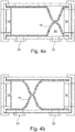
Fig. 4 is a cross-sectional view of the working principle of the pump ofFig. 2 . - The pump system that is described below comprises a
pump 10 having generally tubularelongated pump housing 12 provided with passages at each end thereof, oneinlet passage 14 and oneoutlet passage 16. The passages are arranged with suitable attachment elements for connecting suitable conduits to each passage. The attachment elements may comprise e.g. threads, bayonet fittings, quick couplings of garden hose type, just to mention a few. - The interior of the housing is arranged with a generally tubular flexible element or
membrane 18 such as e.g. a rubber hose. It is however to be understood that other types of material, such as plastic, having the required properties may be utilized. Theflexible element 18 has a shape and dimension so as to contact at least a major part of the inner surface of thehousing 12 when placed inside thehousing 12. The ends of theflexible element 18 are attached to thehousing 12 at the inlet and outlet passages byappropriate attachment elements 20. - The
housing 12 is further arranged with twopassages passages passage 22 is closer to theinlet 14 than theother passage 24. Each passage is arranged with suitable attachment elements such as for example threads. Thepassage 22 closer to theinlet 14 is connected via asuitable conduit 23 to asuitable pressure source 26 that is capable of providing pulsated pressurised air, as will be explained. For instance, acompressor 26 may be used for creating pressurized air and apulse generator 25 may be arranged between thecompressor 26 and thepassage 22 for the air. The pulse generator may for example be a pressure valve that opens above a certain pressure threshold and closes below said pressure threshold. However, there are many other types of pulse generators on the market that may be used, and which are known to the skilled person. - The
compressor 26 is connected to a suitable power source which may be selected from various alternatives, depending on the pump application and on the available power. It may either be connected to a conventional mains power system, tophotovoltaic panels 27a,batteries 27b and/or water or air drivenpower generators - The
outlet passage 24 for the air is arranged with aconduit 28 of a length such that it is ascertained that the outlet of theconduit 28 is well above the liquid level LL in which the pump is submersed. Preferably theconduit 28 is of a non-flexible material and should be dimensioned such that flow-resistance for the passing air is as low as possible. - The
inlet 14 of thehousing 12 is preferably attached to acheck valve 30, either directly or via asuitable conduit 31. Thecheck valve 30 may further be provided with afilter 32 for preventing objects and larger particles from entering thepump 10. Thefilter 32 may either be an ordinary mesh filter, possibly integrated with thecheck valve 30, or it may comprise a combined valve and filter where valve members are placed in the orifices of thefilter 32. Since thepump 10 of the present invention can handle rather large objects having dimensions somewhat smaller than the inner diameter of the pump without being damaged, as will be described below, the orifices may be rather large. -
Figure 3 shows one type of check valve having a generallytubular body 34 with one end in liquid communication with thepump 10. The other end is closed off by a lid orwall 36. Around the circumference of the body a number ofpassages 38 are arranged. Inside the body 34 a generally tube-shapedflexible membrane 40 is arranged having a shape and dimension so as to be in contact with the inner surface of thebody 34. When the interior of thevalve 30 is filled with liquid and thepump 10 is not active, the column of liquid in the pump system that is arranged above thevalve 30 as seen in a vertical direction will press the membrane against the inner surface of the body, effectively closing the passages as seen inFig. 3a . On the other hand, if thepump 10 is active and liquid is drawn by thepump 10, theflexible membrane 40 will flex inwards due to the suction action of thepump 10,Fig. 3b , thereby opening thepassages 38 so that liquid may flow. The size of thepassages 38 is chosen such that larger objects are prevented from entering. - The
outlet passage 16 of thepump 10 is arranged with aconduit 42 of a certain length. The length is chosen such that a column of liquid of a certain weight is obtained. The weight is chosen such that it is ascertained that themembrane 18 is pressed against the inner surface of thepump housing 12. At the upper end of theconduit 42, abranch 44 may be arranged, such as a T-shaped connection. Anexpansion vessel 46 is attached to one of the connections, preferably the vertical connection as seen inFig. 1 . The function of theexpansion vessel 46 is to handle the pressure peaks that are generated when thepump 10 is working in order to smooth out the pressure peaks against the pressure that is formed in the pump system during operation. - Regarding the
conduits passages - If the pump is to be placed in a lake, pond or similar larger water areas, it might be arranged with some type of
buoyancy element 60 such as a plate of floating material that is attached to the pump. Thebuoyancy element 60 may further be arranged with attachment functions such as through-holes, through which anchoringrods 62 may be placed and in turn attached to the lake bottom LB. attachment functions may also or instead include ropes and the like for holding the pump in place. Thebuoyancy element 60 may further function as a lid if the pump is used in a drilled or dug well. - The pump system is intended to function as follows. The
pump 10 is placed in the liquid to be pumped, preferably vertically with itsinlet 14 downwards and itsoutlet 16 upwards. Thepump 10 is placed at such a depth that the outlet passage of theconduit 28 for the compressed air is well above the liquid level. Thecompressor 26 is then activated whereby it delivers compressed air. In that regard, thecompressor 26 might be driven by photovoltaic panels, providing an inexpensive operation in places where there is a lack of electric power. A pulse generator connected to the compressor generates a series of pulses of compressed air. Each pulse of compressed air presses themembrane 18 to be locally radially compressed,Fig. 4a . The pulse of air thus creates anannular fluid compartment 50 that is moving upwards between themembrane 18 and thehousing 12 towards the outlet. - In order to ensure a pumping effect, i.e. creating the local
annular fluid compartment 50, themembrane 18 has to be pressed against the inner surface of thehousing 12 before each new air pulse. The force needed to press themembrane 18 against thehousing 12 is created by the column of liquid that is created by theconduit 42 attached to the liquid outlet, whereby its weight will create the necessary force. It is to be understood that alonger conduit 42 will create a heavier liquid column that will more easily press themembrane 18 against thehousing 12. However, if the weight is too large, that will affect the pumping capacity of the pump. Thus, if the weight increases, then the pressure of the air pulse also has to be increased. Further the liquid column also constitutes the transport of water out of the system. - The
expansion vessel 46 will ensure that the effect of the air pulses are limited and that they are balanced against the pressure of the system as such, where the aim is to have the pump working with as small recoil forces as possible because each air pulse creates a downward movement inside thepump housing 12 when themembrane 18 is compressed and pushes the liquid upwards. - The
check valve 30 at theinlet 14 has an important function because it prevents the liquid that is drawn into thepump 10 from flowing back between the air pulses. On the one hand, anormal check valve 30, possibly integrated with amesh filter 32, may be used. - On the other hand, the simple and yet effective check valve describe above may be utilised for the function. Preferably the same type of tubular membrane is used in the check valve as in the pump. In this manner a very cost-effective solution is obtained. For instance, an ordinary bicycle hose, such as from a BMX-cycle, can be used both in the pump and in the check valve. The number and the size of the
passages 38 in the body of the check-valve may be chosen depending on application. - It is to be understood that the embodiment described above and shown in the drawings is to be regarded only as a non-limiting example and that it may be modified in many ways within the scope of the patent claims.
Claims (17)
- Pump system comprising a pump (10) having a generally cylindrical pump housing (12); which pump housing (12) is arranged with a liquid inlet (14) in one end and a liquid outlet (16) in a second end;- a tubular membrane (18) arranged inside said pump housing (12);- a first passage (22) arranged in the vicinity of said liquid inlet (14) for introducing pressurized fluid between said membrane (18) and said housing (12);- a second passage (24) arranged in the vicinity of said liquid outlet (16) for releasing said pressurized fluid;the membrane (18) is arranged with an elasticity providing a local radial compression and a ring-shaped fluid compartment (50) when a pulse of pressurized fluid is entered through the first passage; wherein said fluid compartment (50) travels along said housing, bringing a volume of liquid with it;
characterised in that the system further comprises an expansion vessel (46) operably attached to said liquid outlet (16) for reducing pressure changes in said liquid caused by the action of said pulse of the pressurized fluid. - Pump system according to claim 1, wherein said pump (10) during operation is positioned with said inlet (14) generally vertically downwards and with said outlet (16) generally vertically upwards.
- Pump system according to claim 2, further comprising a conduit (42) attached to said liquid outlet (16) and being oriented generally vertically for creating a liquid column.
- Pump system according to claim 3, wherein the length of said conduit (42) is chosen such that a liquid column is created having a weight creating a pressure on said membrane (18) ensuring a tight seal between said membrane (18) and an inner surface of said pump housing (12).
- Pump system according to any of the claims 3-4, wherein an upper end of said conduit (42) is arranged with a branch (44), wherein said expansion vessel (46) is attached to one branch and a second branch constitutes an outlet for said liquid.
- Pump system according to any of the preceding claims, further comprising a compressor (26) operably connected to a pulse generator (25) for providing pulses of pressurized fluid to said pump housing.
- Pump system according to claim 6, wherein it further comprises a power generator operably connected to said compressor (26), capable of energizing said compressor.
- Pump system according to claim 7, wherein said power generator comprises one or several of photovoltaic panels (27a), wind turbines (27c), water turbines (27d).
- Pump system according to claim 7 or 8, wherein said power generator comprises at least one battery (27b) operably connected to said compressor (26).
- Pump system according to claim 9 when dependent on claim 8, wherein one said or several of photovoltaic panels, wind turbines, water turbines are arranged to charge said at least one battery (27b).
- Pump system according to any of the preceding claims, further comprising a check valve (30) in liquid communication with said inlet passage (14) of said pump housing (12).
- Pump system according to claim 11, further comprising a filter unit (32) arranged before said check valve (30) relative to a direction of flow of the liquid.
- Pump system according to claim 11, wherein said check valve (30) comprises a generally tubular body (34) provided with a number of passages (38), a generally tubular flexible membrane (40) arranged coaxial with and inside said body (34) having one end of said tubular membrane (40) fixedly attached to said body (34).
- Pump system according to any of the preceding claims, wherein said second passage (24) is arranged with a conduit (28) of such a length as to ensure that its free end is above the liquid level when placed in the liquid.
- Pump system according to any of the preceding claims, wherein said pressurized fluid is pulsated pressurised air.
- Pump system according to any of the preceding claims, wherein said tubular flexible membrane (18) is made of one of a rubber hose and plastic having the required properties.
- Pump system according to any of the preceding claims, wherein said tubular flexible membrane (18) has a shape and dimension so as to contact at least a major part of the inner surface of the housing (12) when placed inside the housing (12) and the ends of the flexible membrane (18) are attached to the housing (12) at the inlet (14) and outlet (16) passages by attachment elements (20).
Applications Claiming Priority (2)
| Application Number | Priority Date | Filing Date | Title |
|---|---|---|---|
| SE1551065 | 2015-08-12 | ||
| PCT/EP2016/067011 WO2017025276A1 (en) | 2015-08-12 | 2016-07-18 | Pump system |
Publications (2)
| Publication Number | Publication Date |
|---|---|
| EP3334933A1 EP3334933A1 (en) | 2018-06-20 |
| EP3334933B1 true EP3334933B1 (en) | 2019-08-21 |
Family
ID=56413688
Family Applications (1)
| Application Number | Title | Priority Date | Filing Date |
|---|---|---|---|
| EP16739172.1A Active EP3334933B1 (en) | 2015-08-12 | 2016-07-18 | Pump system |
Country Status (7)
| Country | Link |
|---|---|
| US (1) | US10837437B2 (en) |
| EP (1) | EP3334933B1 (en) |
| CN (1) | CN107923381B (en) |
| ES (1) | ES2752463T3 (en) |
| TW (1) | TWI617740B (en) |
| WO (1) | WO2017025276A1 (en) |
| ZA (1) | ZA201708627B (en) |
Families Citing this family (1)
| Publication number | Priority date | Publication date | Assignee | Title |
|---|---|---|---|---|
| US20220282723A1 (en) * | 2019-07-25 | 2022-09-08 | Altop Patents Iii B.V. | Cyclic operating pumping method and system |
Family Cites Families (15)
| Publication number | Priority date | Publication date | Assignee | Title |
|---|---|---|---|---|
| US3039309A (en) * | 1957-09-13 | 1962-06-19 | Phillips Petroleum Co | Pneumatically actuated pump and sampling system |
| US3427987A (en) * | 1967-05-15 | 1969-02-18 | Gray Co Inc | Tubular diaphragm pump |
| NL7905463A (en) * | 1979-07-12 | 1981-01-14 | Noord Nederlandsche Maschf | PUMP. |
| US4515536A (en) | 1979-07-12 | 1985-05-07 | Noord-Nederlandsche Machinefabriek B.V. | Perstaltic pump |
| EP0073196A1 (en) * | 1980-11-19 | 1983-03-09 | RIHA, Mirko | Fluid operated diaphragm pump |
| US4580952A (en) * | 1984-06-07 | 1986-04-08 | Eberle William J | Apparatus for lifting liquids from subsurface reservoirs |
| US4802829A (en) * | 1987-02-17 | 1989-02-07 | Miller Michael A | Solar controlled water well |
| JPH01240777A (en) | 1988-03-18 | 1989-09-26 | Kozaburo Nitta | Slurry conveying pipe and slurry conveyer |
| JPH03149373A (en) | 1989-11-02 | 1991-06-25 | Hitachi Ltd | Wave pump, pulsating flow generator, flow measuring device and heat exchange system |
| CN2177107Y (en) * | 1993-11-11 | 1994-09-14 | 陈启松 | Cylindrical jacketed cavity diaphragm pump |
| JP3609313B2 (en) | 2000-02-03 | 2005-01-12 | 株式会社キーアンドクラフト | Transport device |
| SE520389C2 (en) | 2000-09-20 | 2003-07-01 | Stefan Larsson | Pressure operated liquid displacement pump, comprises tubular casing containing flexible membrane hose and ring shaped balloon |
| SE520398C2 (en) * | 2001-11-13 | 2003-07-01 | Cw Lundberg Ind Ab | Method is for fitting load accommodating fixture for roof equipment component on outer roof which is lined with external sealing layer mat |
| CN101156009B (en) * | 2005-04-12 | 2013-03-27 | 艾安·德拉库普·多伊格 | Improvements in valves and pumps |
| US20150118068A1 (en) * | 2013-10-30 | 2015-04-30 | Endow Energy, Llc | Remote sensing of in-ground fluid level apparatus |
-
2016
- 2016-07-18 ES ES16739172T patent/ES2752463T3/en active Active
- 2016-07-18 CN CN201680043711.4A patent/CN107923381B/en active Active
- 2016-07-18 US US15/742,431 patent/US10837437B2/en active Active
- 2016-07-18 EP EP16739172.1A patent/EP3334933B1/en active Active
- 2016-07-18 WO PCT/EP2016/067011 patent/WO2017025276A1/en active Application Filing
- 2016-07-26 TW TW105123593A patent/TWI617740B/en active
-
2017
- 2017-12-18 ZA ZA2017/08627A patent/ZA201708627B/en unknown
Non-Patent Citations (1)
| Title |
|---|
| None * |
Also Published As
| Publication number | Publication date |
|---|---|
| EP3334933A1 (en) | 2018-06-20 |
| CN107923381A (en) | 2018-04-17 |
| ZA201708627B (en) | 2022-05-25 |
| ES2752463T3 (en) | 2020-04-06 |
| WO2017025276A1 (en) | 2017-02-16 |
| TW201712227A (en) | 2017-04-01 |
| US10837437B2 (en) | 2020-11-17 |
| US20180195506A1 (en) | 2018-07-12 |
| CN107923381B (en) | 2019-06-11 |
| TWI617740B (en) | 2018-03-11 |
Similar Documents
| Publication | Publication Date | Title |
|---|---|---|
| EP0421010B1 (en) | Wave powered pumping apparatus and method | |
| JP2008524496A5 (en) | ||
| US10001107B2 (en) | Energy conversion system and method | |
| US9068560B2 (en) | Energy generation system including pressure vessels with flexible bladders having elongate valve tubes contained therein that contain a plurality of flow apertures for communication of fluid therewith | |
| JP2018506953A5 (en) | ||
| US5473892A (en) | Apparatus for generating high pressure fluid in response to water weight changes caused by waves | |
| US10495053B2 (en) | Wave energy converter with a differential cylinder | |
| CN108757288B (en) | Water-gas common-capacity cabin power energy storage system and method using deep-sea constant-pressure gas storage tank for constant pressure | |
| EP3334933B1 (en) | Pump system | |
| US5349819A (en) | Apparatus for generating high pressure water in response to water weight changes caused by waves | |
| EP2123903A1 (en) | Device for converting wave energy into electrical energy | |
| CN111630274A (en) | Deep well pump and method of use | |
| RU168152U1 (en) | Pulse supercharger | |
| ES2633840B1 (en) | High pressure hydraulic pumping system without external energy consumption and procedure for its implementation | |
| CN209838796U (en) | Water pumping device | |
| CN108474365A (en) | Reciprocating pump | |
| CN218933305U (en) | System for improving water potential energy by utilizing air extraction and water diversion modes | |
| US5711655A (en) | Pump system using a vacuum chamber and mechanical pump combinations | |
| CN217482237U (en) | Injection pipe for water pump | |
| CN210715123U (en) | High-pressure pump | |
| CN212296701U (en) | Wave energy power generation device | |
| CN212273047U (en) | Water pump sealing device with combined dynamic sealing sheet and static sealing sheet | |
| RU2705697C1 (en) | Hydro pneumatic pump | |
| GB2501239A (en) | Wave operated pump with secondary chamber providing restoring force | |
| WO2023043791A1 (en) | Wave powered one way fluid flow generator |
Legal Events
| Date | Code | Title | Description |
|---|---|---|---|
| STAA | Information on the status of an ep patent application or granted ep patent |
Free format text: STATUS: THE INTERNATIONAL PUBLICATION HAS BEEN MADE |
|
| PUAI | Public reference made under article 153(3) epc to a published international application that has entered the european phase |
Free format text: ORIGINAL CODE: 0009012 |
|
| STAA | Information on the status of an ep patent application or granted ep patent |
Free format text: STATUS: REQUEST FOR EXAMINATION WAS MADE |
|
| 17P | Request for examination filed |
Effective date: 20171212 |
|
| AK | Designated contracting states |
Kind code of ref document: A1 Designated state(s): AL AT BE BG CH CY CZ DE DK EE ES FI FR GB GR HR HU IE IS IT LI LT LU LV MC MK MT NL NO PL PT RO RS SE SI SK SM TR |
|
| AX | Request for extension of the european patent |
Extension state: BA ME |
|
| DAV | Request for validation of the european patent (deleted) | ||
| DAX | Request for extension of the european patent (deleted) | ||
| RAP1 | Party data changed (applicant data changed or rights of an application transferred) |
Owner name: SHL MEDICAL AG |
|
| GRAP | Despatch of communication of intention to grant a patent |
Free format text: ORIGINAL CODE: EPIDOSNIGR1 |
|
| STAA | Information on the status of an ep patent application or granted ep patent |
Free format text: STATUS: GRANT OF PATENT IS INTENDED |
|
| INTG | Intention to grant announced |
Effective date: 20190327 |
|
| GRAS | Grant fee paid |
Free format text: ORIGINAL CODE: EPIDOSNIGR3 |
|
| GRAA | (expected) grant |
Free format text: ORIGINAL CODE: 0009210 |
|
| STAA | Information on the status of an ep patent application or granted ep patent |
Free format text: STATUS: THE PATENT HAS BEEN GRANTED |
|
| AK | Designated contracting states |
Kind code of ref document: B1 Designated state(s): AL AT BE BG CH CY CZ DE DK EE ES FI FR GB GR HR HU IE IS IT LI LT LU LV MC MK MT NL NO PL PT RO RS SE SI SK SM TR |
|
| REG | Reference to a national code |
Ref country code: GB Ref legal event code: FG4D |
|
| RAP2 | Party data changed (patent owner data changed or rights of a patent transferred) |
Owner name: SHL MEDICAL AG |
|
| REG | Reference to a national code |
Ref country code: CH Ref legal event code: EP |
|
| REG | Reference to a national code |
Ref country code: DE Ref legal event code: R096 Ref document number: 602016019045 Country of ref document: DE |
|
| REG | Reference to a national code |
Ref country code: AT Ref legal event code: REF Ref document number: 1170065 Country of ref document: AT Kind code of ref document: T Effective date: 20190915 |
|
| REG | Reference to a national code |
Ref country code: IE Ref legal event code: FG4D |
|
| REG | Reference to a national code |
Ref country code: NL Ref legal event code: FP |
|
| REG | Reference to a national code |
Ref country code: LT Ref legal event code: MG4D |
|
| PG25 | Lapsed in a contracting state [announced via postgrant information from national office to epo] |
Ref country code: PT Free format text: LAPSE BECAUSE OF FAILURE TO SUBMIT A TRANSLATION OF THE DESCRIPTION OR TO PAY THE FEE WITHIN THE PRESCRIBED TIME-LIMIT Effective date: 20191223 Ref country code: BG Free format text: LAPSE BECAUSE OF FAILURE TO SUBMIT A TRANSLATION OF THE DESCRIPTION OR TO PAY THE FEE WITHIN THE PRESCRIBED TIME-LIMIT Effective date: 20191121 Ref country code: NO Free format text: LAPSE BECAUSE OF FAILURE TO SUBMIT A TRANSLATION OF THE DESCRIPTION OR TO PAY THE FEE WITHIN THE PRESCRIBED TIME-LIMIT Effective date: 20191121 Ref country code: LT Free format text: LAPSE BECAUSE OF FAILURE TO SUBMIT A TRANSLATION OF THE DESCRIPTION OR TO PAY THE FEE WITHIN THE PRESCRIBED TIME-LIMIT Effective date: 20190821 Ref country code: FI Free format text: LAPSE BECAUSE OF FAILURE TO SUBMIT A TRANSLATION OF THE DESCRIPTION OR TO PAY THE FEE WITHIN THE PRESCRIBED TIME-LIMIT Effective date: 20190821 Ref country code: SE Free format text: LAPSE BECAUSE OF FAILURE TO SUBMIT A TRANSLATION OF THE DESCRIPTION OR TO PAY THE FEE WITHIN THE PRESCRIBED TIME-LIMIT Effective date: 20190821 Ref country code: HR Free format text: LAPSE BECAUSE OF FAILURE TO SUBMIT A TRANSLATION OF THE DESCRIPTION OR TO PAY THE FEE WITHIN THE PRESCRIBED TIME-LIMIT Effective date: 20190821 |
|
| PG25 | Lapsed in a contracting state [announced via postgrant information from national office to epo] |
Ref country code: AL Free format text: LAPSE BECAUSE OF FAILURE TO SUBMIT A TRANSLATION OF THE DESCRIPTION OR TO PAY THE FEE WITHIN THE PRESCRIBED TIME-LIMIT Effective date: 20190821 Ref country code: LV Free format text: LAPSE BECAUSE OF FAILURE TO SUBMIT A TRANSLATION OF THE DESCRIPTION OR TO PAY THE FEE WITHIN THE PRESCRIBED TIME-LIMIT Effective date: 20190821 Ref country code: GR Free format text: LAPSE BECAUSE OF FAILURE TO SUBMIT A TRANSLATION OF THE DESCRIPTION OR TO PAY THE FEE WITHIN THE PRESCRIBED TIME-LIMIT Effective date: 20191122 Ref country code: RS Free format text: LAPSE BECAUSE OF FAILURE TO SUBMIT A TRANSLATION OF THE DESCRIPTION OR TO PAY THE FEE WITHIN THE PRESCRIBED TIME-LIMIT Effective date: 20190821 Ref country code: IS Free format text: LAPSE BECAUSE OF FAILURE TO SUBMIT A TRANSLATION OF THE DESCRIPTION OR TO PAY THE FEE WITHIN THE PRESCRIBED TIME-LIMIT Effective date: 20191221 |
|
| REG | Reference to a national code |
Ref country code: AT Ref legal event code: MK05 Ref document number: 1170065 Country of ref document: AT Kind code of ref document: T Effective date: 20190821 |
|
| PG25 | Lapsed in a contracting state [announced via postgrant information from national office to epo] |
Ref country code: TR Free format text: LAPSE BECAUSE OF FAILURE TO SUBMIT A TRANSLATION OF THE DESCRIPTION OR TO PAY THE FEE WITHIN THE PRESCRIBED TIME-LIMIT Effective date: 20190821 |
|
| REG | Reference to a national code |
Ref country code: ES Ref legal event code: FG2A Ref document number: 2752463 Country of ref document: ES Kind code of ref document: T3 Effective date: 20200406 |
|
| PG25 | Lapsed in a contracting state [announced via postgrant information from national office to epo] |
Ref country code: IT Free format text: LAPSE BECAUSE OF FAILURE TO SUBMIT A TRANSLATION OF THE DESCRIPTION OR TO PAY THE FEE WITHIN THE PRESCRIBED TIME-LIMIT Effective date: 20190821 Ref country code: DK Free format text: LAPSE BECAUSE OF FAILURE TO SUBMIT A TRANSLATION OF THE DESCRIPTION OR TO PAY THE FEE WITHIN THE PRESCRIBED TIME-LIMIT Effective date: 20190821 Ref country code: PL Free format text: LAPSE BECAUSE OF FAILURE TO SUBMIT A TRANSLATION OF THE DESCRIPTION OR TO PAY THE FEE WITHIN THE PRESCRIBED TIME-LIMIT Effective date: 20190821 Ref country code: AT Free format text: LAPSE BECAUSE OF FAILURE TO SUBMIT A TRANSLATION OF THE DESCRIPTION OR TO PAY THE FEE WITHIN THE PRESCRIBED TIME-LIMIT Effective date: 20190821 Ref country code: EE Free format text: LAPSE BECAUSE OF FAILURE TO SUBMIT A TRANSLATION OF THE DESCRIPTION OR TO PAY THE FEE WITHIN THE PRESCRIBED TIME-LIMIT Effective date: 20190821 Ref country code: RO Free format text: LAPSE BECAUSE OF FAILURE TO SUBMIT A TRANSLATION OF THE DESCRIPTION OR TO PAY THE FEE WITHIN THE PRESCRIBED TIME-LIMIT Effective date: 20190821 |
|
| PG25 | Lapsed in a contracting state [announced via postgrant information from national office to epo] |
Ref country code: IS Free format text: LAPSE BECAUSE OF FAILURE TO SUBMIT A TRANSLATION OF THE DESCRIPTION OR TO PAY THE FEE WITHIN THE PRESCRIBED TIME-LIMIT Effective date: 20200224 Ref country code: CZ Free format text: LAPSE BECAUSE OF FAILURE TO SUBMIT A TRANSLATION OF THE DESCRIPTION OR TO PAY THE FEE WITHIN THE PRESCRIBED TIME-LIMIT Effective date: 20190821 Ref country code: SM Free format text: LAPSE BECAUSE OF FAILURE TO SUBMIT A TRANSLATION OF THE DESCRIPTION OR TO PAY THE FEE WITHIN THE PRESCRIBED TIME-LIMIT Effective date: 20190821 Ref country code: SK Free format text: LAPSE BECAUSE OF FAILURE TO SUBMIT A TRANSLATION OF THE DESCRIPTION OR TO PAY THE FEE WITHIN THE PRESCRIBED TIME-LIMIT Effective date: 20190821 |
|
| REG | Reference to a national code |
Ref country code: DE Ref legal event code: R097 Ref document number: 602016019045 Country of ref document: DE |
|
| PLBE | No opposition filed within time limit |
Free format text: ORIGINAL CODE: 0009261 |
|
| STAA | Information on the status of an ep patent application or granted ep patent |
Free format text: STATUS: NO OPPOSITION FILED WITHIN TIME LIMIT |
|
| PG2D | Information on lapse in contracting state deleted |
Ref country code: IS |
|
| 26N | No opposition filed |
Effective date: 20200603 |
|
| PG25 | Lapsed in a contracting state [announced via postgrant information from national office to epo] |
Ref country code: SI Free format text: LAPSE BECAUSE OF FAILURE TO SUBMIT A TRANSLATION OF THE DESCRIPTION OR TO PAY THE FEE WITHIN THE PRESCRIBED TIME-LIMIT Effective date: 20190821 |
|
| PG25 | Lapsed in a contracting state [announced via postgrant information from national office to epo] |
Ref country code: MC Free format text: LAPSE BECAUSE OF FAILURE TO SUBMIT A TRANSLATION OF THE DESCRIPTION OR TO PAY THE FEE WITHIN THE PRESCRIBED TIME-LIMIT Effective date: 20190821 |
|
| REG | Reference to a national code |
Ref country code: CH Ref legal event code: PUE Owner name: SPOWDI AB, SE Free format text: FORMER OWNER: SHL MEDICAL AG, CH |
|
| REG | Reference to a national code |
Ref country code: BE Ref legal event code: MM Effective date: 20200731 |
|
| PG25 | Lapsed in a contracting state [announced via postgrant information from national office to epo] |
Ref country code: LU Free format text: LAPSE BECAUSE OF NON-PAYMENT OF DUE FEES Effective date: 20200718 |
|
| PG25 | Lapsed in a contracting state [announced via postgrant information from national office to epo] |
Ref country code: BE Free format text: LAPSE BECAUSE OF NON-PAYMENT OF DUE FEES Effective date: 20200731 |
|
| REG | Reference to a national code |
Ref country code: DE Ref legal event code: R081 Ref document number: 602016019045 Country of ref document: DE Owner name: SPODWI AB, SE Free format text: FORMER OWNER: SHL MEDICAL AG, ZUG, CH |
|
| REG | Reference to a national code |
Ref country code: NL Ref legal event code: PD Owner name: SPOWDI AB; SE Free format text: DETAILS ASSIGNMENT: CHANGE OF OWNER(S), ASSIGNMENT; FORMER OWNER NAME: SHL MEDICAL AG Effective date: 20210713 |
|
| PG25 | Lapsed in a contracting state [announced via postgrant information from national office to epo] |
Ref country code: IE Free format text: LAPSE BECAUSE OF NON-PAYMENT OF DUE FEES Effective date: 20200718 |
|
| REG | Reference to a national code |
Ref country code: GB Ref legal event code: 732E Free format text: REGISTERED BETWEEN 20210805 AND 20210811 |
|
| PG25 | Lapsed in a contracting state [announced via postgrant information from national office to epo] |
Ref country code: MT Free format text: LAPSE BECAUSE OF FAILURE TO SUBMIT A TRANSLATION OF THE DESCRIPTION OR TO PAY THE FEE WITHIN THE PRESCRIBED TIME-LIMIT Effective date: 20190821 Ref country code: CY Free format text: LAPSE BECAUSE OF FAILURE TO SUBMIT A TRANSLATION OF THE DESCRIPTION OR TO PAY THE FEE WITHIN THE PRESCRIBED TIME-LIMIT Effective date: 20190821 |
|
| PG25 | Lapsed in a contracting state [announced via postgrant information from national office to epo] |
Ref country code: MK Free format text: LAPSE BECAUSE OF FAILURE TO SUBMIT A TRANSLATION OF THE DESCRIPTION OR TO PAY THE FEE WITHIN THE PRESCRIBED TIME-LIMIT Effective date: 20190821 |
|
| P01 | Opt-out of the competence of the unified patent court (upc) registered |
Effective date: 20230425 |
|
| PGFP | Annual fee paid to national office [announced via postgrant information from national office to epo] |
Ref country code: NL Payment date: 20230614 Year of fee payment: 8 Ref country code: FR Payment date: 20230622 Year of fee payment: 8 |
|
| PGFP | Annual fee paid to national office [announced via postgrant information from national office to epo] |
Ref country code: GB Payment date: 20230601 Year of fee payment: 8 Ref country code: ES Payment date: 20230808 Year of fee payment: 8 Ref country code: CH Payment date: 20230801 Year of fee payment: 8 |
|
| PGFP | Annual fee paid to national office [announced via postgrant information from national office to epo] |
Ref country code: DE Payment date: 20230607 Year of fee payment: 8 |