EP3334261A1 - Central-string inverter device - Google Patents
Central-string inverter device Download PDFInfo
- Publication number
- EP3334261A1 EP3334261A1 EP17174207.5A EP17174207A EP3334261A1 EP 3334261 A1 EP3334261 A1 EP 3334261A1 EP 17174207 A EP17174207 A EP 17174207A EP 3334261 A1 EP3334261 A1 EP 3334261A1
- Authority
- EP
- European Patent Office
- Prior art keywords
- string
- container
- central
- inverters
- inverter device
- Prior art date
- Legal status (The legal status is an assumption and is not a legal conclusion. Google has not performed a legal analysis and makes no representation as to the accuracy of the status listed.)
- Granted
Links
Images



Classifications
-
- H—ELECTRICITY
- H02—GENERATION; CONVERSION OR DISTRIBUTION OF ELECTRIC POWER
- H02M—APPARATUS FOR CONVERSION BETWEEN AC AND AC, BETWEEN AC AND DC, OR BETWEEN DC AND DC, AND FOR USE WITH MAINS OR SIMILAR POWER SUPPLY SYSTEMS; CONVERSION OF DC OR AC INPUT POWER INTO SURGE OUTPUT POWER; CONTROL OR REGULATION THEREOF
- H02M7/00—Conversion of AC power input into DC power output; Conversion of DC power input into AC power output
- H02M7/003—Constructional details, e.g. physical layout, assembly, wiring or busbar connections
-
- H—ELECTRICITY
- H02—GENERATION; CONVERSION OR DISTRIBUTION OF ELECTRIC POWER
- H02J—ELECTRIC POWER NETWORKS; CIRCUIT ARRANGEMENTS OR SYSTEMS FOR SUPPLYING OR DISTRIBUTING ELECTRIC POWER; SYSTEMS FOR STORING ELECTRIC ENERGY
- H02J1/00—Circuit arrangements for DC mains or DC distribution networks
- H02J1/10—Parallel operation of DC sources
- H02J1/102—Parallel operation of DC sources being switching converters
-
- H—ELECTRICITY
- H02—GENERATION; CONVERSION OR DISTRIBUTION OF ELECTRIC POWER
- H02M—APPARATUS FOR CONVERSION BETWEEN AC AND AC, BETWEEN AC AND DC, OR BETWEEN DC AND DC, AND FOR USE WITH MAINS OR SIMILAR POWER SUPPLY SYSTEMS; CONVERSION OF DC OR AC INPUT POWER INTO SURGE OUTPUT POWER; CONTROL OR REGULATION THEREOF
- H02M7/00—Conversion of AC power input into DC power output; Conversion of DC power input into AC power output
- H02M7/42—Conversion of DC power input into AC power output without possibility of reversal
-
- H—ELECTRICITY
- H05—ELECTRIC TECHNIQUES NOT OTHERWISE PROVIDED FOR
- H05K—PRINTED CIRCUITS; CASINGS OR CONSTRUCTIONAL DETAILS OF ELECTRIC APPARATUS; MANUFACTURE OF ASSEMBLAGES OF ELECTRICAL COMPONENTS
- H05K7/00—Constructional details common to different types of electric apparatus
- H05K7/14—Mounting supporting structure in casing or on frame or rack
- H05K7/1422—Printed circuit boards receptacles, e.g. stacked structures, electronic circuit modules or box like frames
- H05K7/1427—Housings
-
- H—ELECTRICITY
- H05—ELECTRIC TECHNIQUES NOT OTHERWISE PROVIDED FOR
- H05K—PRINTED CIRCUITS; CASINGS OR CONSTRUCTIONAL DETAILS OF ELECTRIC APPARATUS; MANUFACTURE OF ASSEMBLAGES OF ELECTRICAL COMPONENTS
- H05K7/00—Constructional details common to different types of electric apparatus
- H05K7/20—Modifications to facilitate cooling, ventilating, or heating
-
- H—ELECTRICITY
- H05—ELECTRIC TECHNIQUES NOT OTHERWISE PROVIDED FOR
- H05K—PRINTED CIRCUITS; CASINGS OR CONSTRUCTIONAL DETAILS OF ELECTRIC APPARATUS; MANUFACTURE OF ASSEMBLAGES OF ELECTRICAL COMPONENTS
- H05K7/00—Constructional details common to different types of electric apparatus
- H05K7/20—Modifications to facilitate cooling, ventilating, or heating
- H05K7/20009—Modifications to facilitate cooling, ventilating, or heating using a gaseous coolant in electronic enclosures
-
- H—ELECTRICITY
- H05—ELECTRIC TECHNIQUES NOT OTHERWISE PROVIDED FOR
- H05K—PRINTED CIRCUITS; CASINGS OR CONSTRUCTIONAL DETAILS OF ELECTRIC APPARATUS; MANUFACTURE OF ASSEMBLAGES OF ELECTRICAL COMPONENTS
- H05K7/00—Constructional details common to different types of electric apparatus
- H05K7/20—Modifications to facilitate cooling, ventilating, or heating
- H05K7/20536—Modifications to facilitate cooling, ventilating, or heating for racks or cabinets of standardised dimensions, e.g. electronic racks for aircraft or telecommunication equipment
- H05K7/20554—Forced ventilation of a gaseous coolant
- H05K7/2059—Forced ventilation of a gaseous coolant within rooms for removing heat from cabinets, e.g. by air conditioning device
-
- H—ELECTRICITY
- H05—ELECTRIC TECHNIQUES NOT OTHERWISE PROVIDED FOR
- H05K—PRINTED CIRCUITS; CASINGS OR CONSTRUCTIONAL DETAILS OF ELECTRIC APPARATUS; MANUFACTURE OF ASSEMBLAGES OF ELECTRICAL COMPONENTS
- H05K7/00—Constructional details common to different types of electric apparatus
- H05K7/20—Modifications to facilitate cooling, ventilating, or heating
- H05K7/2089—Modifications to facilitate cooling, ventilating, or heating for power electronics, e.g. for inverters for controlling motor
- H05K7/20909—Forced ventilation, e.g. on heat dissipaters coupled to components
Definitions
- the present disclosure relates to an inverter, and in particular to a central-string inverter device.
- a container-type inverter device with a power higher than 1MW is adopted usually. More than two high power inverters (with a power higher than 500kW) are integrated in the container to form a central inverter device, which has advantages of easy installation, easy maintenance, small occupation, low cost and the like.
- the high power inverter is directly made into an outdoor cabinet to form a single inverter device with a power higher than 1MW.
- these two types of inverter device have a small amount of MPPTs (generally 2 to 4 MPPTs) due to design limitations, which cannot meet a requirement of multiple MPPT control for complex terrain. Thus energy yield is greatly affected.
- the present disclosure provides a central-string inverter device formed by integrating multiple string inverters into a container.
- the number of MPPTs of this device may reach 20 or more.
- the string inverters are integrated into the container, the installation, maintenance and heat radiation are a big issue.
- the central-string inverter device according to the present disclosure can be easily installed, maintained and is advantageous for heat radiation.
- a central-string inverter device includes a container and multiple string inverters installed in the container.
- the multiple string inverters are arranged in two rows located respectively on two opposite sides of the container.
- An intermediate duct is formed between the two rows of string inverters.
- An air outlet is arranged on each of side walls of the two opposite sides of the container.
- An air inlet is arranged on each of side walls of the other two opposite sides of the container or on a bottom wall of the container.
- Pulling structures corresponding to the multiple string inverters are arranged on a string inverter bracket which is installed on a bottom wall of the container. Each of the string inverters is installed or removed through the corresponding pulling structure.
- an isolation duct is arranged on each of the side walls of the container having the air outlet.
- a maintenance door is installed on the side wall of the container having the air outlet.
- the air outlet is arranged on the maintenance door.
- a maintenance door is installed on the side wall of the container having the air inlet.
- the air inlet is arranged on the maintenance door.
- the maintenance door is a wire mesh door, on which meshes form the air outlet or the air inlet.
- each row of string inverters is divided into a upper region and a lower region in the arrangement direction, and a regional duct communicating with the intermediate duct is formed between the upper region and the lower region of the string inverters in the same row.
- the pulling structure is in a pulling manner of sliding contact or in a pulling manner of pulley.
- multiple sliding blocks are arranged at the bottom of each of the string inverters and a track corresponding to the sliding blocks is arranged on the string inverter bracket which is install on the bottom wall of the container; or a track is arranged at the bottom of each of the string inverters and a sliding block corresponding to the track is arranged on the string inverter bracket which is installed on the bottom wall of the container.
- the pulling structure is in the pulling manner of pulley
- multiple pulleys are arranged at the bottom of each of the string inverters and a track corresponding to the pulleys is arranged on the string inverter bracket which is installed on the bottom wall of the container; or a track is arranged at the bottom of each of the string inverters and a pulley corresponding to the track is arranged on the string inverter bracket which is installed on the bottom wall of the container.
- the central-string inverter device further includes an accessory device installed in the container, which is configured to assist the string inverters to operate normally.
- the central-string inverter device has the following advantages.
- the central-string inverter device includes a container 1, multiple string inverters 2 and an accessory device 5.
- the string inverters 2 and the accessory device 5 are installed in the container 1.
- the accessory device 5 is configured to assist the string inverters 2 to operate normally, and may include subsidiary devices such as a switching device, a power distribution device and a communication device.
- the technical solution in the present disclosure is suitable for the case of two or more string inverters, up to 20 string inverters or even more.
- the design for installing the string inverter 2 in the container 1 is as follows.
- the multiple string inverters 2 are arranged in two rows located respectively on two opposite sides of the container 1.
- An intermediate duct 3 is formed between the two rows of string inverters 2.
- An air outlet 11 is arranged on each of side walls of the two opposite sides of the container 1.
- An air inlet 12 is arranged on each of the other two opposite sides of the container 1.
- Pulling structures corresponding to the multiple string inverters 2 are arranged on the two opposite sides of the container 1.
- Each string inverter 2 is installed or removed through the pulling structure.
- the string inverters 2 are arranged in an array on both sides of the intermediate duct 3 in the container 1.
- the string inverters may be stacked when needed. Therefore the string inverters may be arranged in only one layer, or in two or more layers. In the present embodiment, an example of two layers of the string inverters is described for illustration.
- An isolation duct 13 may be arranged on each of the side walls of the container having the air outlet 11. Incoming and outgoing wires of the string inverters 2 may be concentrated in the isolation duct 13.
- the isolation duct 13 isolates the hot air discharged from the string inverter 2 from the inner space of the container 1. The hot air is discharged directly to the outside environment of the container 1 through the isolation duct 13 and the air outlet 11.
- Ducts of the string inverters 2 are separately arranged and do not affect each other. Compared with conventional inverters, each of the string inverters 2 operates independently without affecting each other. If failure occurs in one of the string inverters 2, this string inverter may be individually maintained, so that operation of the other string inverters 2 will not be affected.
- Each string inverter 2 in the central-string inverter device according to the present disclosure is installed or removed through the pulling structure, so as to facilitate the installation, maintenance and heat radiation.
- the pulling structure may be in a pulling manner of sliding contact or in a pulling manner of pulley.
- the pulling structure may be in the pulling manner of sliding contact.
- multiple sliding blocks 21 are arranged at the bottom of each string inverter 2 and a track 6 corresponding to the sliding blocks 21 is arranged on a string inverter bracket which is installed on the bottom wall of the container 1.
- the stability between the string inverters 2 and the track 6 can be improved.
- the track 6 may be only provided, and the bottom surface of the string inverter 2 serves as a natural slide block.
- a wear-resisting slide block e.g. made of epoxy resin
- matching the track 6 may be added on the bottom of the string inverter 2, which can reduce the damage to the track 6.
- the track 6 may be installed on the string inverter bracket which is installed on the bottom wall of the container 1 (not shown in Figure 4 ).
- a track may be arranged at the bottom of each string inverter 2 and a slide block corresponding to the track may be arranged on the string inverter bracket which is installed on the bottom wall of the container 1.
- the pulling structure may be in the pulling manner of pulley.
- a pulley 7 is arranged at the bottom of each string inverter 2 and a track 6 corresponding to the pulley 7 is arranged on the string inverter bracket which is installed on the bottom wall of the container 1.
- the track 6 may not be provided.
- a track may be arranged on the bottom of each string inverter 2 and a pulley corresponding to the track may be arranged on the string inverter bracket which is installed on the bottom wall of the container 1.
- the central-string inverter device according to the second embodiment is basically the same as the central-string inverter device according to the first embodiment.
- the difference lies in that, in the central-string inverter device according to the second embodiment, maintenance doors 14 are installed on the side wall of the container 1 having the air outlet 11 and on the side wall of the container 1 having the air inlet 12.
- the air inlet 12 and the air outlet 11 are arranged on the corresponding maintenance door 14.
- the number of maintenance doors 14 may be determined according to actual need.
- a front maintenance door on a front side, a rear maintenance door on a rear side, a right maintenance door on a right side and a left maintenance door on a left side may be provided.
- only one of the above maintenance doors may be provided.
- the string inverter 2 is installed on the string inverter bracket (not shown in Figure) inside the container 1 by means of pulling, or a string inverting is pulled out to perform maintenance such as overhaul. In this way, installation, wiring, operation and maintenance of the string inverters 2 may be performed by opening the front or rear maintenance door without entering into the container 1.
- the central-string inverter device according to the third embodiment is basically the same as the central-string inverter device according to the second embodiment. The difference lies in that, in the central-string inverter device according to the third embodiment, the maintenance door 14 is a wire mesh door, on which meshes forms the air outlet 11 or the air inlet 12.
- the string inverter 2 has a high ingress protection level (such as IP55 or above), a low ingress protection may be adopted for the container 1.
- the wire mesh door design may be adopted to meet the outdoor requirement.
- the isolate duct 13 may not be arranged for air exhaust of the string inverter. Hot air passes through the mesh of the wire mesh door and is discharged directly to the outside environment.
- the string inverter 2 is maintained in a manner as described in the above embodiment.
- the container 1 does not need the isolation duct 13, air outlet 11, air inlet 12 and other structural parts, thereby saving the cost.
- the wire mesh door is removed on the basis of the third embodiment.
- the periphery of the container 1 is completely open, and only a top and a bottom of the container 1 are left, which further saves cost and makes the installation and maintenance more convenient.
- the central-string inverter device according to the fifth embodiment is basically the same as the central-string inverter device according to the first embodiment. The difference lies in that, in the central-string inverter device according to the fifth embodiment, the air inlet 12 is arranged on the bottom wall of the container 1.
- each row of string inverters 2 is divided into a upper region and a lower region in the arrangement direction, and a regional duct 4 communicating with the intermediate duct 3 is formed between the upper region and the lower region of the string inverters 2 in the same row.
- the way that air inlet is arranged on the bottom of the string inverter and the air outlet is arranged on side of the string inverter set is also convenient for incoming and outgoing of wind. Understandably, the device according to the second embodiment, the third embodiment and the fourth embodiment may also be modified in the manner that the air inlet is arranged on the bottom.
- multiple string inverters 2 are integrated into the container 1 in an array, thereby meeting the requirement of multiple MPPT control.
- the isolation duct 13 is adopted in the heat irradiation duct of the present disclosure for isolating the cold hair and hot air. Maintenance can be performed from outside without entering into the container, and the thus fire passage can be omitted.
- Each of the string inverters 2 operates independently without affecting each other, which is convenient for maintenance.
Landscapes
- Engineering & Computer Science (AREA)
- Microelectronics & Electronic Packaging (AREA)
- Physics & Mathematics (AREA)
- Thermal Sciences (AREA)
- Power Engineering (AREA)
- Aviation & Aerospace Engineering (AREA)
- Inverter Devices (AREA)
- Ventilation (AREA)
Abstract
Description
- The present disclosure relates to an inverter, and in particular to a central-string inverter device.
- In a large-scale ground power station, a container-type inverter device with a power higher than 1MW is adopted usually. More than two high power inverters (with a power higher than 500kW) are integrated in the container to form a central inverter device, which has advantages of easy installation, easy maintenance, small occupation, low cost and the like. Alternatively, in a large-scale ground power station, the high power inverter is directly made into an outdoor cabinet to form a single inverter device with a power higher than 1MW. However, these two types of inverter device have a small amount of MPPTs (generally 2 to 4 MPPTs) due to design limitations, which cannot meet a requirement of multiple MPPT control for complex terrain. Thus energy yield is greatly affected.
- In order to address the issue of requirement for multiple MPPTs, the present disclosure provides a central-string inverter device formed by integrating multiple string inverters into a container. The number of MPPTs of this device may reach 20 or more. In addition, since the string inverters are integrated into the container, the installation, maintenance and heat radiation are a big issue. The central-string inverter device according to the present disclosure can be easily installed, maintained and is advantageous for heat radiation.
- The technical solution of the present disclosure is described hereinafter. A central-string inverter device includes a container and multiple string inverters installed in the container. The multiple string inverters are arranged in two rows located respectively on two opposite sides of the container. An intermediate duct is formed between the two rows of string inverters. An air outlet is arranged on each of side walls of the two opposite sides of the container. An air inlet is arranged on each of side walls of the other two opposite sides of the container or on a bottom wall of the container. Pulling structures corresponding to the multiple string inverters are arranged on a string inverter bracket which is installed on a bottom wall of the container. Each of the string inverters is installed or removed through the corresponding pulling structure.
- As a further improvement of the above solution, an isolation duct is arranged on each of the side walls of the container having the air outlet.
- As a further improvement of the above solution, a maintenance door is installed on the side wall of the container having the air outlet.
- Further, the air outlet is arranged on the maintenance door.
- As a further improvement of the above solution, a maintenance door is installed on the side wall of the container having the air inlet.
- Further, the air inlet is arranged on the maintenance door.
- Even further, the maintenance door is a wire mesh door, on which meshes form the air outlet or the air inlet.
- As a further improvement of the above solution, if the air inlet is arranged on the bottom wall of the container, each row of string inverters is divided into a upper region and a lower region in the arrangement direction, and a regional duct communicating with the intermediate duct is formed between the upper region and the lower region of the string inverters in the same row.
- As a further improvement of the above solution, the pulling structure is in a pulling manner of sliding contact or in a pulling manner of pulley.
- If the pulling structure is in the pulling manner of sliding contact, multiple sliding blocks are arranged at the bottom of each of the string inverters and a track corresponding to the sliding blocks is arranged on the string inverter bracket which is install on the bottom wall of the container; or a track is arranged at the bottom of each of the string inverters and a sliding block corresponding to the track is arranged on the string inverter bracket which is installed on the bottom wall of the container.
- If the pulling structure is in the pulling manner of pulley, multiple pulleys are arranged at the bottom of each of the string inverters and a track corresponding to the pulleys is arranged on the string inverter bracket which is installed on the bottom wall of the container; or a track is arranged at the bottom of each of the string inverters and a pulley corresponding to the track is arranged on the string inverter bracket which is installed on the bottom wall of the container.
- As a further improvement of the above solution, the central-string inverter device further includes an accessory device installed in the container, which is configured to assist the string inverters to operate normally.
- The central-string inverter device according to the present disclosure has the following advantages.
- 1. Multiple string inverters are integrated into the container to form a central-string inverter device, which can achieve multiple MPPTs, so that the inverter may be adapt to more situations of power plant.
- 2. The isolation duct is designed for the central-string inverter device, so that hot air and cold air can be completely isolated, to avoid affection on the heat radiation of the system due to short-cut of the hot air and the cold air.
- 3. Installation and maintenance can be performed completely from outside without entering into the container. The use of fire passage inside the container and the resulting issues can be avoided, so that the space of the fire passage can be fully used to increase the actual usage area of the container.
- 4. Compared with separated string inverters, the installation and maintenance is more convenient.
- 5. Each of the string inverters operates independently without affecting each other. If a failure occurs in one of the string inverters, this string inverter may be maintained and replaced directly by the pulling operation, without affecting operations of the other string inverters.
-
-
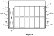
Figure 1 is a front view of a central-string inverter device according to a first embodiment of the present disclosure; -
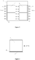
Figure 2 is a top view of the central-string inverter device inFigure 1 ; -
Figure 3 is a right side view of the central-string inverter device inFigure 1 ; -
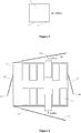
Figure 4 is a schematic structural diagram of a pulling structure of a string inverter of the central-string inverter device inFigure 1 ; -
Figure 5 , similar toFigure 4 , is a schematic structural diagram of another pulling structure; -
Figure 6 is a top view of a central-string inverter device according to a second embodiment of the present disclosure; -
Figure 7 is a top view of a central-string inverter device according to a third embodiment of the present disclosure; -
Figure 8 is a top view of a central-string inverter device according to a fourth embodiment of the present disclosure; and -
Figure 9 is a right view of a central-string inverter device according to a fifth embodiment of the present disclosure. - In order to make the objects, technical solutions and advantages of the present disclosure more clear, the present disclosure will be described in detail with reference to the accompanying drawings and embodiments. It should be understood that the specific embodiments described herein are only for the purpose of illustration and are not to be construed as the limitation of the present disclosure.
- Referring to
Figures 1 to 3 , the central-string inverter device according to the present disclosure includes acontainer 1,multiple string inverters 2 and an accessory device 5.Thestring inverters 2 and theaccessory device 5 are installed in thecontainer 1. Theaccessory device 5 is configured to assist thestring inverters 2 to operate normally, and may include subsidiary devices such as a switching device, a power distribution device and a communication device. - The technical solution in the present disclosure is suitable for the case of two or more string inverters, up to 20 string inverters or even more. The design for installing the
string inverter 2 in thecontainer 1 is as follows. Themultiple string inverters 2 are arranged in two rows located respectively on two opposite sides of thecontainer 1. Anintermediate duct 3 is formed between the two rows ofstring inverters 2. Anair outlet 11 is arranged on each of side walls of the two opposite sides of thecontainer 1. Anair inlet 12 is arranged on each of the other two opposite sides of thecontainer 1. Pulling structures corresponding to themultiple string inverters 2 are arranged on the two opposite sides of thecontainer 1. Eachstring inverter 2 is installed or removed through the pulling structure. - The
string inverters 2 are arranged in an array on both sides of theintermediate duct 3 in thecontainer 1. The string inverters may be stacked when needed. Therefore the string inverters may be arranged in only one layer, or in two or more layers. In the present embodiment, an example of two layers of the string inverters is described for illustration. Anisolation duct 13 may be arranged on each of the side walls of the container having theair outlet 11. Incoming and outgoing wires of thestring inverters 2 may be concentrated in theisolation duct 13. - Cold air enters into the
container 1 from theair inlets 12 on the left and right sides of thecontainer 1 and then passes through each of thestring inverters 2 for heat radiation. After that, the air enters into theisolation duct 13. Theisolation duct 13 isolates the hot air discharged from thestring inverter 2 from the inner space of thecontainer 1. The hot air is discharged directly to the outside environment of thecontainer 1 through theisolation duct 13 and theair outlet 11. - Ducts of the
string inverters 2 are separately arranged and do not affect each other. Compared with conventional inverters, each of thestring inverters 2 operates independently without affecting each other. If failure occurs in one of thestring inverters 2, this string inverter may be individually maintained, so that operation of theother string inverters 2 will not be affected. - Since the
string inverters 2 are integrated into thecontainer 1, the installation, maintenance and heat radiation is a big issue. Eachstring inverter 2 in the central-string inverter device according to the present disclosure is installed or removed through the pulling structure, so as to facilitate the installation, maintenance and heat radiation. The pulling structure may be in a pulling manner of sliding contact or in a pulling manner of pulley. - Referring to
Figure 4 , the pulling structure may be in the pulling manner of sliding contact. For example, multiple slidingblocks 21 are arranged at the bottom of eachstring inverter 2 and atrack 6 corresponding to the slidingblocks 21 is arranged on a string inverter bracket which is installed on the bottom wall of thecontainer 1. With this pulling manner of sliding contact of thestring inverters 2, the stability between thestring inverters 2 and thetrack 6 can be improved. Apparently, thetrack 6 may be only provided, and the bottom surface of thestring inverter 2 serves as a natural slide block. For ease of pulling, a wear-resisting slide block (e.g. made of epoxy resin) matching thetrack 6 may be added on the bottom of thestring inverter 2, which can reduce the damage to thetrack 6. Thetrack 6 may be installed on the string inverter bracket which is installed on the bottom wall of the container 1 (not shown inFigure 4 ). Apparently, in other embodiments, a track may be arranged at the bottom of eachstring inverter 2 and a slide block corresponding to the track may be arranged on the string inverter bracket which is installed on the bottom wall of thecontainer 1. - Referring to
Figure 5 , the pulling structure may be in the pulling manner of pulley. For example, apulley 7 is arranged at the bottom of eachstring inverter 2 and atrack 6 corresponding to thepulley 7 is arranged on the string inverter bracket which is installed on the bottom wall of thecontainer 1. Apparently, thetrack 6 may not be provided. Alternatively, a track may be arranged on the bottom of eachstring inverter 2 and a pulley corresponding to the track may be arranged on the string inverter bracket which is installed on the bottom wall of thecontainer 1. With this pulling manner of pulley, the pulling is more convenient. By installingmultiple pulleys 7 corresponding to thetrack 6 on the bottom of thestring inverter 2, sliding movement is changed into rolling movement, which greatly reduces frication for pulling, making pulling maintenance more convenient. - Referring to
Figure 6 , the central-string inverter device according to the second embodiment is basically the same as the central-string inverter device according to the first embodiment. The difference lies in that, in the central-string inverter device according to the second embodiment,maintenance doors 14 are installed on the side wall of thecontainer 1 having theair outlet 11 and on the side wall of thecontainer 1 having theair inlet 12. Preferably, theair inlet 12 and theair outlet 11 are arranged on thecorresponding maintenance door 14. - The number of
maintenance doors 14 may be determined according to actual need. A front maintenance door on a front side, a rear maintenance door on a rear side, a right maintenance door on a right side and a left maintenance door on a left side may be provided. Alternatively, only one of the above maintenance doors may be provided. When installing or maintaining, the front and rear maintenance doors are opened, thestring inverter 2 is installed on the string inverter bracket (not shown in Figure) inside thecontainer 1 by means of pulling, or a string inverting is pulled out to perform maintenance such as overhaul. In this way, installation, wiring, operation and maintenance of thestring inverters 2 may be performed by opening the front or rear maintenance door without entering into thecontainer 1. - Referring to
Figure 7 , the central-string inverter device according to the third embodiment is basically the same as the central-string inverter device according to the second embodiment. The difference lies in that, in the central-string inverter device according to the third embodiment, themaintenance door 14 is a wire mesh door, on which meshes forms theair outlet 11 or theair inlet 12. - In order to meet different needs, for example, if the
string inverter 2 has a high ingress protection level (such as IP55 or above), a low ingress protection may be adopted for thecontainer 1. As shown inFigure 7 , the wire mesh door design may be adopted to meet the outdoor requirement. The isolateduct 13 may not be arranged for air exhaust of the string inverter. Hot air passes through the mesh of the wire mesh door and is discharged directly to the outside environment. Thestring inverter 2 is maintained in a manner as described in the above embodiment. Thecontainer 1 does not need theisolation duct 13,air outlet 11,air inlet 12 and other structural parts, thereby saving the cost. - Referring to
Figure 8 , the wire mesh door is removed on the basis of the third embodiment. The periphery of thecontainer 1 is completely open, and only a top and a bottom of thecontainer 1 are left, which further saves cost and makes the installation and maintenance more convenient. - Referring to
Figure 9 , the central-string inverter device according to the fifth embodiment is basically the same as the central-string inverter device according to the first embodiment. The difference lies in that, in the central-string inverter device according to the fifth embodiment, theair inlet 12 is arranged on the bottom wall of thecontainer 1. - In the case that the
air inlet 12 is arranged on the bottom wall of thecontainer 1, each row ofstring inverters 2 is divided into a upper region and a lower region in the arrangement direction, and aregional duct 4 communicating with theintermediate duct 3 is formed between the upper region and the lower region of thestring inverters 2 in the same row. The way that air inlet is arranged on the bottom of the string inverter and the air outlet is arranged on side of the string inverter set is also convenient for incoming and outgoing of wind. Understandably, the device according to the second embodiment, the third embodiment and the fourth embodiment may also be modified in the manner that the air inlet is arranged on the bottom. - In view of the above embodiments, in the present disclosure,
multiple string inverters 2 are integrated into thecontainer 1 in an array, thereby meeting the requirement of multiple MPPT control. Theisolation duct 13 is adopted in the heat irradiation duct of the present disclosure for isolating the cold hair and hot air. Maintenance can be performed from outside without entering into the container, and the thus fire passage can be omitted. Each of thestring inverters 2 operates independently without affecting each other, which is convenient for maintenance. - The above only describes preferred embodiment of the present disclosure and is not to limit the present disclosure. Any changes, equivalents and modifications which are made within the spirit and principle of the present disclosure shall fall within the protection scope of the present disclosure.
Claims (10)
- A central-string inverter device, comprising
a container (1), and
a plurality of string inverters (2) installed in the container (1), wherein
the plurality of string inverters (2) are arranged in two rows located respectively on two opposite sides of the container (1);
an intermediate duct (3) is formed between the two rows of string inverters (2);
an air outlet (11) is arranged on each of side walls of the two opposite sides of the container (1);
an air inlet (12) is arranged on each of side walls of the other two opposite sides of the container (1) or on a bottom wall of the container (1);
pulling structures corresponding to the plurality of string inverters (2) are arranged on a string inverter bracket which is installed on a bottom wall of the container (1), each of the string inverters (2) is installed or removed through the corresponding pulling structure. - The central-string inverter device according to claim 1, wherein an isolation duct (13) is arranged on each of the side walls of the container (1) having the air outlet (11).
- The central-string inverter device according to claim 1, wherein a maintenance door (14) is installed on the side wall of the container (1) having the air outlet (11).
- The central-string inverter device according to claim 3, wherein the air outlet (11) is arranged on the maintenance door (14).
- The central-string inverter device according to claim 1, wherein a maintenance door (14) is installed on the side wall of the container (1) having the air inlet (12).
- The central-string inverter device according to claim 5, wherein the air inlet (12) is arranged on the maintenance door (14).
- The central-string inverter device according to claim 3 or 5, wherein the maintenance door (14) is a wire mesh door, on which meshes form the air outlet (11) or the air inlet (12).
- The central-string inverter device according to claim 1, wherein, if the air inlet (12) is arranged on the bottom wall of the container (1), each row of string inverters (2) is divided into a upper region and a lower region in the arrangement direction, and a regional duct (4) communicating with the intermediate duct (3) is formed between the upper region and the lower region of the string inverters (2) in the same row.
- The central-string inverter device according to claim 1, wherein the pulling structure is in a pulling manner of sliding contact or in a pulling manner of pulley;
if the pulling structure is in the pulling manner of sliding contact, a plurality of sliding blocks are arranged at the bottom of each of the string inverters (2) and a track corresponding to the sliding blocks is arranged on the string inverter bracket which is install on the bottom wall of the container (1); or a track is arranged at the bottom of each of the string inverters (2) and a sliding block corresponding to the track is arranged on the string inverter bracket which is install on the bottom wall of the container (1);
if the pulling structure is in the pulling manner of pulley, a plurality of pulleys are arranged at the bottom of each of the string inverters (2) and a track corresponding to the pulleys is arranged on the string inverter bracket which is install on the bottom wall of the container (1); or a track is arranged at the bottom of each of the string inverters (2) and a pulley corresponding to the track is arranged on the string inverter bracket which is install on the bottom wall of the container (1). - The central-string inverter device according to claim 1, wherein the central-string inverter device further comprises an accessory device installed in the container (1), which is configured to assist the string inverters (2) to operate normally.
Priority Applications (1)
| Application Number | Priority Date | Filing Date | Title |
|---|---|---|---|
| PL17174207T PL3334261T3 (en) | 2016-12-12 | 2017-06-02 | Central-string inverter device |
Applications Claiming Priority (1)
| Application Number | Priority Date | Filing Date | Title |
|---|---|---|---|
| CN201621358025.XU CN206237325U (en) | 2016-12-12 | 2016-12-12 | One kind collection string data contravariant equipment |
Publications (2)
| Publication Number | Publication Date |
|---|---|
| EP3334261A1 true EP3334261A1 (en) | 2018-06-13 |
| EP3334261B1 EP3334261B1 (en) | 2021-08-25 |
Family
ID=58991799
Family Applications (1)
| Application Number | Title | Priority Date | Filing Date |
|---|---|---|---|
| EP17174207.5A Active EP3334261B1 (en) | 2016-12-12 | 2017-06-02 | Central-string inverter device |
Country Status (6)
| Country | Link |
|---|---|
| US (1) | US10038391B2 (en) |
| EP (1) | EP3334261B1 (en) |
| CN (1) | CN206237325U (en) |
| CA (1) | CA2968619C (en) |
| ES (1) | ES2890025T3 (en) |
| PL (1) | PL3334261T3 (en) |
Cited By (1)
| Publication number | Priority date | Publication date | Assignee | Title |
|---|---|---|---|---|
| CN113497424A (en) * | 2020-04-07 | 2021-10-12 | 深圳市科信通信技术股份有限公司 | BBU concentrated cabinet |
Families Citing this family (3)
| Publication number | Priority date | Publication date | Assignee | Title |
|---|---|---|---|---|
| CN108306207A (en) * | 2018-01-16 | 2018-07-20 | 闽南理工学院 | A kind of electrical low-voltage cabinet of full-automatic drawing and pulling type of compartmentalization |
| CN112821781B (en) * | 2021-02-19 | 2023-08-11 | 阳光电源股份有限公司 | Power cabinet |
| CN115514193B (en) * | 2022-11-17 | 2023-06-06 | 杭州思拓瑞吉科技有限公司 | Power device and manufacturing method thereof |
Citations (8)
| Publication number | Priority date | Publication date | Assignee | Title |
|---|---|---|---|---|
| US20100302731A1 (en) * | 2009-05-15 | 2010-12-02 | Belikoff Michael A | Inverter Cooler |
| US20120077427A1 (en) * | 2010-09-24 | 2012-03-29 | Hon Hai Precision Industry Co., Ltd. | Container data center and heat dissipation system |
| US20120155027A1 (en) * | 2010-12-16 | 2012-06-21 | Broome John P | Portable computer server enclosure |
| CN202954588U (en) * | 2012-10-25 | 2013-05-29 | 苏州景新电气有限公司 | Preassembled photovoltaic inversion container |
| JP2013149905A (en) * | 2012-01-23 | 2013-08-01 | Fujitsu Fsas Inc | Rack system |
| GB2500196A (en) * | 2012-03-12 | 2013-09-18 | Barratt Energy Ltd | Solar power plant comprising inverter modules housed in a shipping container |
| US20140319985A1 (en) * | 2013-04-26 | 2014-10-30 | Fujitsu Limited | Movement mechanism and rack housing structure |
| CN204167717U (en) * | 2014-10-30 | 2015-02-18 | 阳光电源股份有限公司 | A kind of photovoltaic combining inverter equipment |
Family Cites Families (7)
| Publication number | Priority date | Publication date | Assignee | Title |
|---|---|---|---|---|
| DE102007005436B4 (en) * | 2007-01-30 | 2014-08-07 | Platinum Gmbh | Carrier module for an inverter |
| JP5895452B2 (en) * | 2011-10-31 | 2016-03-30 | 富士電機株式会社 | Inverter device |
| WO2013080345A1 (en) * | 2011-11-30 | 2013-06-06 | 三菱電機株式会社 | Forced-air-cooled power conversion device |
| US9407164B2 (en) * | 2012-02-03 | 2016-08-02 | Massachusetts Institute Of Technology | Systems approach to photovoltaic energy extraction |
| EP2931012A1 (en) * | 2014-04-07 | 2015-10-14 | Siemens Aktiengesellschaft | Subsea power cell arrangement |
| JP2016032367A (en) * | 2014-07-29 | 2016-03-07 | 株式会社安川電機 | Power converter |
| US11210617B2 (en) * | 2015-10-08 | 2021-12-28 | Johnson Controls Technology Company | Building management system with electrical energy storage optimization based on benefits and costs of participating in PDBR and IBDR programs |
-
2016
- 2016-12-12 CN CN201621358025.XU patent/CN206237325U/en active Active
-
2017
- 2017-05-30 CA CA2968619A patent/CA2968619C/en active Active
- 2017-06-02 ES ES17174207T patent/ES2890025T3/en active Active
- 2017-06-02 EP EP17174207.5A patent/EP3334261B1/en active Active
- 2017-06-02 PL PL17174207T patent/PL3334261T3/en unknown
- 2017-06-22 US US15/630,118 patent/US10038391B2/en active Active
Patent Citations (8)
| Publication number | Priority date | Publication date | Assignee | Title |
|---|---|---|---|---|
| US20100302731A1 (en) * | 2009-05-15 | 2010-12-02 | Belikoff Michael A | Inverter Cooler |
| US20120077427A1 (en) * | 2010-09-24 | 2012-03-29 | Hon Hai Precision Industry Co., Ltd. | Container data center and heat dissipation system |
| US20120155027A1 (en) * | 2010-12-16 | 2012-06-21 | Broome John P | Portable computer server enclosure |
| JP2013149905A (en) * | 2012-01-23 | 2013-08-01 | Fujitsu Fsas Inc | Rack system |
| GB2500196A (en) * | 2012-03-12 | 2013-09-18 | Barratt Energy Ltd | Solar power plant comprising inverter modules housed in a shipping container |
| CN202954588U (en) * | 2012-10-25 | 2013-05-29 | 苏州景新电气有限公司 | Preassembled photovoltaic inversion container |
| US20140319985A1 (en) * | 2013-04-26 | 2014-10-30 | Fujitsu Limited | Movement mechanism and rack housing structure |
| CN204167717U (en) * | 2014-10-30 | 2015-02-18 | 阳光电源股份有限公司 | A kind of photovoltaic combining inverter equipment |
Cited By (1)
| Publication number | Priority date | Publication date | Assignee | Title |
|---|---|---|---|---|
| CN113497424A (en) * | 2020-04-07 | 2021-10-12 | 深圳市科信通信技术股份有限公司 | BBU concentrated cabinet |
Also Published As
| Publication number | Publication date |
|---|---|
| US20180166996A1 (en) | 2018-06-14 |
| CA2968619A1 (en) | 2018-06-12 |
| CN206237325U (en) | 2017-06-09 |
| US10038391B2 (en) | 2018-07-31 |
| CA2968619C (en) | 2020-09-01 |
| ES2890025T3 (en) | 2022-01-17 |
| EP3334261B1 (en) | 2021-08-25 |
| PL3334261T3 (en) | 2022-02-07 |
Similar Documents
| Publication | Publication Date | Title |
|---|---|---|
| CA2968619C (en) | Central-string inverter device | |
| CN105515108A (en) | Large-power charging pile having two-cavity three-door cabinet body | |
| CN202954588U (en) | Preassembled photovoltaic inversion container | |
| CN105680345A (en) | Front patch panel cabinet | |
| CN109274026B (en) | Combined photovoltaic substation | |
| CN202059068U (en) | Low-voltage drawing type switch cabinet | |
| CN108666884A (en) | Secondary device rack in a kind of prefabricated cabin | |
| CN205248643U (en) | Preceding wiring front maintenance's direct current divides electric cabinet | |
| CN201577243U (en) | ONU integrated machine cabinet | |
| CN211557748U (en) | Outdoor array shelter rack unit | |
| CN203983936U (en) | Prefabricated cabin fiber optic cable transfer box | |
| CN204651710U (en) | A kind of outdoor distribution low-voltage comprehensive distribution box | |
| CN203761060U (en) | Distributed access system | |
| CN218183779U (en) | Prefabricated square bin and square bin module | |
| CN203554314U (en) | Photovoltaic inverter room protective structure | |
| CN107809066B (en) | Centralized cable routing module for prefabricated cabin and prefabricated cabin using this module | |
| CN205123049U (en) | Secondary cable box | |
| CN209488033U (en) | A New Substation Structure | |
| CN108964482B (en) | A distribution network flexible DC converter | |
| CN204615230U (en) | A kind of complete indoor two-layer transformer station of 35kV split transformer | |
| CN206143800U (en) | Photovoltaic exchanges collection flow box mounting structure | |
| CN216958935U (en) | Secondary equipment integration module and offshore booster station based on same | |
| CN216930512U (en) | Modular intelligent floor box | |
| CN216134192U (en) | Mounting structure of power distribution network automation equipment | |
| CN211295921U (en) | Heat dissipation cabinet door and equipment installation cabinet |
Legal Events
| Date | Code | Title | Description |
|---|---|---|---|
| PUAI | Public reference made under article 153(3) epc to a published international application that has entered the european phase |
Free format text: ORIGINAL CODE: 0009012 |
|
| STAA | Information on the status of an ep patent application or granted ep patent |
Free format text: STATUS: THE APPLICATION HAS BEEN PUBLISHED |
|
| AK | Designated contracting states |
Kind code of ref document: A1 Designated state(s): AL AT BE BG CH CY CZ DE DK EE ES FI FR GB GR HR HU IE IS IT LI LT LU LV MC MK MT NL NO PL PT RO RS SE SI SK SM TR |
|
| AX | Request for extension of the european patent |
Extension state: BA ME |
|
| STAA | Information on the status of an ep patent application or granted ep patent |
Free format text: STATUS: REQUEST FOR EXAMINATION WAS MADE |
|
| 17P | Request for examination filed |
Effective date: 20181213 |
|
| RBV | Designated contracting states (corrected) |
Designated state(s): AL AT BE BG CH CY CZ DE DK EE ES FI FR GB GR HR HU IE IS IT LI LT LU LV MC MK MT NL NO PL PT RO RS SE SI SK SM TR |
|
| STAA | Information on the status of an ep patent application or granted ep patent |
Free format text: STATUS: EXAMINATION IS IN PROGRESS |
|
| 17Q | First examination report despatched |
Effective date: 20201210 |
|
| GRAP | Despatch of communication of intention to grant a patent |
Free format text: ORIGINAL CODE: EPIDOSNIGR1 |
|
| STAA | Information on the status of an ep patent application or granted ep patent |
Free format text: STATUS: GRANT OF PATENT IS INTENDED |
|
| RIC1 | Information provided on ipc code assigned before grant |
Ipc: H02M 7/00 20060101ALI20210309BHEP Ipc: H05K 7/20 20060101AFI20210309BHEP |
|
| INTG | Intention to grant announced |
Effective date: 20210324 |
|
| GRAS | Grant fee paid |
Free format text: ORIGINAL CODE: EPIDOSNIGR3 |
|
| GRAA | (expected) grant |
Free format text: ORIGINAL CODE: 0009210 |
|
| STAA | Information on the status of an ep patent application or granted ep patent |
Free format text: STATUS: THE PATENT HAS BEEN GRANTED |
|
| AK | Designated contracting states |
Kind code of ref document: B1 Designated state(s): AL AT BE BG CH CY CZ DE DK EE ES FI FR GB GR HR HU IE IS IT LI LT LU LV MC MK MT NL NO PL PT RO RS SE SI SK SM TR |
|
| REG | Reference to a national code |
Ref country code: CH Ref legal event code: EP |
|
| REG | Reference to a national code |
Ref country code: NL Ref legal event code: FP |
|
| REG | Reference to a national code |
Ref country code: IE Ref legal event code: FG4D Ref country code: AT Ref legal event code: REF Ref document number: 1425181 Country of ref document: AT Kind code of ref document: T Effective date: 20210915 |
|
| REG | Reference to a national code |
Ref country code: DE Ref legal event code: R096 Ref document number: 602017044588 Country of ref document: DE |
|
| REG | Reference to a national code |
Ref country code: LT Ref legal event code: MG9D |
|
| REG | Reference to a national code |
Ref country code: AT Ref legal event code: MK05 Ref document number: 1425181 Country of ref document: AT Kind code of ref document: T Effective date: 20210825 |
|
| REG | Reference to a national code |
Ref country code: ES Ref legal event code: FG2A Ref document number: 2890025 Country of ref document: ES Kind code of ref document: T3 Effective date: 20220117 |
|
| PG25 | Lapsed in a contracting state [announced via postgrant information from national office to epo] |
Ref country code: RS Free format text: LAPSE BECAUSE OF FAILURE TO SUBMIT A TRANSLATION OF THE DESCRIPTION OR TO PAY THE FEE WITHIN THE PRESCRIBED TIME-LIMIT Effective date: 20210825 Ref country code: SE Free format text: LAPSE BECAUSE OF FAILURE TO SUBMIT A TRANSLATION OF THE DESCRIPTION OR TO PAY THE FEE WITHIN THE PRESCRIBED TIME-LIMIT Effective date: 20210825 Ref country code: PT Free format text: LAPSE BECAUSE OF FAILURE TO SUBMIT A TRANSLATION OF THE DESCRIPTION OR TO PAY THE FEE WITHIN THE PRESCRIBED TIME-LIMIT Effective date: 20211227 Ref country code: NO Free format text: LAPSE BECAUSE OF FAILURE TO SUBMIT A TRANSLATION OF THE DESCRIPTION OR TO PAY THE FEE WITHIN THE PRESCRIBED TIME-LIMIT Effective date: 20211125 Ref country code: FI Free format text: LAPSE BECAUSE OF FAILURE TO SUBMIT A TRANSLATION OF THE DESCRIPTION OR TO PAY THE FEE WITHIN THE PRESCRIBED TIME-LIMIT Effective date: 20210825 Ref country code: HR Free format text: LAPSE BECAUSE OF FAILURE TO SUBMIT A TRANSLATION OF THE DESCRIPTION OR TO PAY THE FEE WITHIN THE PRESCRIBED TIME-LIMIT Effective date: 20210825 Ref country code: BG Free format text: LAPSE BECAUSE OF FAILURE TO SUBMIT A TRANSLATION OF THE DESCRIPTION OR TO PAY THE FEE WITHIN THE PRESCRIBED TIME-LIMIT Effective date: 20211125 Ref country code: AT Free format text: LAPSE BECAUSE OF FAILURE TO SUBMIT A TRANSLATION OF THE DESCRIPTION OR TO PAY THE FEE WITHIN THE PRESCRIBED TIME-LIMIT Effective date: 20210825 Ref country code: LT Free format text: LAPSE BECAUSE OF FAILURE TO SUBMIT A TRANSLATION OF THE DESCRIPTION OR TO PAY THE FEE WITHIN THE PRESCRIBED TIME-LIMIT Effective date: 20210825 |
|
| PG25 | Lapsed in a contracting state [announced via postgrant information from national office to epo] |
Ref country code: LV Free format text: LAPSE BECAUSE OF FAILURE TO SUBMIT A TRANSLATION OF THE DESCRIPTION OR TO PAY THE FEE WITHIN THE PRESCRIBED TIME-LIMIT Effective date: 20210825 Ref country code: GR Free format text: LAPSE BECAUSE OF FAILURE TO SUBMIT A TRANSLATION OF THE DESCRIPTION OR TO PAY THE FEE WITHIN THE PRESCRIBED TIME-LIMIT Effective date: 20211126 |
|
| PG25 | Lapsed in a contracting state [announced via postgrant information from national office to epo] |
Ref country code: DK Free format text: LAPSE BECAUSE OF FAILURE TO SUBMIT A TRANSLATION OF THE DESCRIPTION OR TO PAY THE FEE WITHIN THE PRESCRIBED TIME-LIMIT Effective date: 20210825 |
|
| REG | Reference to a national code |
Ref country code: DE Ref legal event code: R097 Ref document number: 602017044588 Country of ref document: DE |
|
| PG25 | Lapsed in a contracting state [announced via postgrant information from national office to epo] |
Ref country code: SM Free format text: LAPSE BECAUSE OF FAILURE TO SUBMIT A TRANSLATION OF THE DESCRIPTION OR TO PAY THE FEE WITHIN THE PRESCRIBED TIME-LIMIT Effective date: 20210825 Ref country code: SK Free format text: LAPSE BECAUSE OF FAILURE TO SUBMIT A TRANSLATION OF THE DESCRIPTION OR TO PAY THE FEE WITHIN THE PRESCRIBED TIME-LIMIT Effective date: 20210825 Ref country code: RO Free format text: LAPSE BECAUSE OF FAILURE TO SUBMIT A TRANSLATION OF THE DESCRIPTION OR TO PAY THE FEE WITHIN THE PRESCRIBED TIME-LIMIT Effective date: 20210825 Ref country code: EE Free format text: LAPSE BECAUSE OF FAILURE TO SUBMIT A TRANSLATION OF THE DESCRIPTION OR TO PAY THE FEE WITHIN THE PRESCRIBED TIME-LIMIT Effective date: 20210825 Ref country code: CZ Free format text: LAPSE BECAUSE OF FAILURE TO SUBMIT A TRANSLATION OF THE DESCRIPTION OR TO PAY THE FEE WITHIN THE PRESCRIBED TIME-LIMIT Effective date: 20210825 Ref country code: AL Free format text: LAPSE BECAUSE OF FAILURE TO SUBMIT A TRANSLATION OF THE DESCRIPTION OR TO PAY THE FEE WITHIN THE PRESCRIBED TIME-LIMIT Effective date: 20210825 |
|
| PLBE | No opposition filed within time limit |
Free format text: ORIGINAL CODE: 0009261 |
|
| STAA | Information on the status of an ep patent application or granted ep patent |
Free format text: STATUS: NO OPPOSITION FILED WITHIN TIME LIMIT |
|
| 26N | No opposition filed |
Effective date: 20220527 |
|
| PG25 | Lapsed in a contracting state [announced via postgrant information from national office to epo] |
Ref country code: SI Free format text: LAPSE BECAUSE OF FAILURE TO SUBMIT A TRANSLATION OF THE DESCRIPTION OR TO PAY THE FEE WITHIN THE PRESCRIBED TIME-LIMIT Effective date: 20210825 |
|
| PG25 | Lapsed in a contracting state [announced via postgrant information from national office to epo] |
Ref country code: MC Free format text: LAPSE BECAUSE OF FAILURE TO SUBMIT A TRANSLATION OF THE DESCRIPTION OR TO PAY THE FEE WITHIN THE PRESCRIBED TIME-LIMIT Effective date: 20210825 |
|
| REG | Reference to a national code |
Ref country code: CH Ref legal event code: PL |
|
| REG | Reference to a national code |
Ref country code: BE Ref legal event code: MM Effective date: 20220630 |
|
| GBPC | Gb: european patent ceased through non-payment of renewal fee |
Effective date: 20220602 |
|
| PG25 | Lapsed in a contracting state [announced via postgrant information from national office to epo] |
Ref country code: LU Free format text: LAPSE BECAUSE OF NON-PAYMENT OF DUE FEES Effective date: 20220602 Ref country code: LI Free format text: LAPSE BECAUSE OF NON-PAYMENT OF DUE FEES Effective date: 20220630 Ref country code: IE Free format text: LAPSE BECAUSE OF NON-PAYMENT OF DUE FEES Effective date: 20220602 Ref country code: CH Free format text: LAPSE BECAUSE OF NON-PAYMENT OF DUE FEES Effective date: 20220630 |
|
| PG25 | Lapsed in a contracting state [announced via postgrant information from national office to epo] |
Ref country code: GB Free format text: LAPSE BECAUSE OF NON-PAYMENT OF DUE FEES Effective date: 20220602 Ref country code: BE Free format text: LAPSE BECAUSE OF NON-PAYMENT OF DUE FEES Effective date: 20220630 |
|
| P01 | Opt-out of the competence of the unified patent court (upc) registered |
Effective date: 20230426 |
|
| PG25 | Lapsed in a contracting state [announced via postgrant information from national office to epo] |
Ref country code: HU Free format text: LAPSE BECAUSE OF FAILURE TO SUBMIT A TRANSLATION OF THE DESCRIPTION OR TO PAY THE FEE WITHIN THE PRESCRIBED TIME-LIMIT; INVALID AB INITIO Effective date: 20170602 |
|
| PG25 | Lapsed in a contracting state [announced via postgrant information from national office to epo] |
Ref country code: MK Free format text: LAPSE BECAUSE OF FAILURE TO SUBMIT A TRANSLATION OF THE DESCRIPTION OR TO PAY THE FEE WITHIN THE PRESCRIBED TIME-LIMIT Effective date: 20210825 Ref country code: CY Free format text: LAPSE BECAUSE OF FAILURE TO SUBMIT A TRANSLATION OF THE DESCRIPTION OR TO PAY THE FEE WITHIN THE PRESCRIBED TIME-LIMIT Effective date: 20210825 |
|
| PG25 | Lapsed in a contracting state [announced via postgrant information from national office to epo] |
Ref country code: TR Free format text: LAPSE BECAUSE OF FAILURE TO SUBMIT A TRANSLATION OF THE DESCRIPTION OR TO PAY THE FEE WITHIN THE PRESCRIBED TIME-LIMIT Effective date: 20210825 |
|
| PG25 | Lapsed in a contracting state [announced via postgrant information from national office to epo] |
Ref country code: MT Free format text: LAPSE BECAUSE OF FAILURE TO SUBMIT A TRANSLATION OF THE DESCRIPTION OR TO PAY THE FEE WITHIN THE PRESCRIBED TIME-LIMIT Effective date: 20210825 |
|
| PGFP | Annual fee paid to national office [announced via postgrant information from national office to epo] |
Ref country code: PL Payment date: 20250516 Year of fee payment: 9 |
|
| PGFP | Annual fee paid to national office [announced via postgrant information from national office to epo] |
Ref country code: NL Payment date: 20250630 Year of fee payment: 9 |
|
| PGFP | Annual fee paid to national office [announced via postgrant information from national office to epo] |
Ref country code: FR Payment date: 20250626 Year of fee payment: 9 |
|
| PGFP | Annual fee paid to national office [announced via postgrant information from national office to epo] |
Ref country code: ES Payment date: 20250701 Year of fee payment: 9 |
|
| PGFP | Annual fee paid to national office [announced via postgrant information from national office to epo] |
Ref country code: DE Payment date: 20250701 Year of fee payment: 9 |
|
| PGFP | Annual fee paid to national office [announced via postgrant information from national office to epo] |
Ref country code: IT Payment date: 20250626 Year of fee payment: 9 |