EP3334136A1 - Kommunikationssystem, kommunikationsvorrichtung, kommunikationsverfahren, endgerät und programm - Google Patents
Kommunikationssystem, kommunikationsvorrichtung, kommunikationsverfahren, endgerät und programm Download PDFInfo
- Publication number
- EP3334136A1 EP3334136A1 EP16833070.2A EP16833070A EP3334136A1 EP 3334136 A1 EP3334136 A1 EP 3334136A1 EP 16833070 A EP16833070 A EP 16833070A EP 3334136 A1 EP3334136 A1 EP 3334136A1
- Authority
- EP
- European Patent Office
- Prior art keywords
- terminal
- network
- area network
- wireless lan
- wide area
- Prior art date
- Legal status (The legal status is an assumption and is not a legal conclusion. Google has not performed a legal analysis and makes no representation as to the accuracy of the status listed.)
- Granted
Links
Images


Classifications
-
- H—ELECTRICITY
- H04—ELECTRIC COMMUNICATION TECHNIQUE
- H04W—WIRELESS COMMUNICATION NETWORKS
- H04W48/00—Access restriction; Network selection; Access point selection
- H04W48/18—Selecting a network or a communication service
-
- H—ELECTRICITY
- H04—ELECTRIC COMMUNICATION TECHNIQUE
- H04L—TRANSMISSION OF DIGITAL INFORMATION, e.g. TELEGRAPHIC COMMUNICATION
- H04L12/00—Data switching networks
- H04L12/66—Arrangements for connecting between networks having differing types of switching systems, e.g. gateways
-
- H—ELECTRICITY
- H04—ELECTRIC COMMUNICATION TECHNIQUE
- H04M—TELEPHONIC COMMUNICATION
- H04M3/00—Automatic or semi-automatic exchanges
-
- H—ELECTRICITY
- H04—ELECTRIC COMMUNICATION TECHNIQUE
- H04W—WIRELESS COMMUNICATION NETWORKS
- H04W4/00—Services specially adapted for wireless communication networks; Facilities therefor
-
- H—ELECTRICITY
- H04—ELECTRIC COMMUNICATION TECHNIQUE
- H04W—WIRELESS COMMUNICATION NETWORKS
- H04W4/00—Services specially adapted for wireless communication networks; Facilities therefor
- H04W4/24—Accounting or billing
-
- H—ELECTRICITY
- H04—ELECTRIC COMMUNICATION TECHNIQUE
- H04W—WIRELESS COMMUNICATION NETWORKS
- H04W4/00—Services specially adapted for wireless communication networks; Facilities therefor
- H04W4/30—Services specially adapted for particular environments, situations or purposes
- H04W4/40—Services specially adapted for particular environments, situations or purposes for vehicles, e.g. vehicle-to-pedestrians [V2P]
-
- H—ELECTRICITY
- H04—ELECTRIC COMMUNICATION TECHNIQUE
- H04W—WIRELESS COMMUNICATION NETWORKS
- H04W8/00—Network data management
- H04W8/18—Processing of user or subscriber data, e.g. subscribed services, user preferences or user profiles; Transfer of user or subscriber data
-
- H—ELECTRICITY
- H04—ELECTRIC COMMUNICATION TECHNIQUE
- H04M—TELEPHONIC COMMUNICATION
- H04M15/00—Arrangements for metering, time-control or time indication ; Metering, charging or billing arrangements for voice wireline or wireless communications, e.g. VoIP
- H04M15/81—Dynamic pricing, e.g. change of tariff during call
-
- H—ELECTRICITY
- H04—ELECTRIC COMMUNICATION TECHNIQUE
- H04W—WIRELESS COMMUNICATION NETWORKS
- H04W88/00—Devices specially adapted for wireless communication networks, e.g. terminals, base stations or access point devices
- H04W88/02—Terminal devices
- H04W88/06—Terminal devices adapted for operation in multiple networks or having at least two operational modes, e.g. multi-mode terminals
-
- H—ELECTRICITY
- H04—ELECTRIC COMMUNICATION TECHNIQUE
- H04W—WIRELESS COMMUNICATION NETWORKS
- H04W92/00—Interfaces specially adapted for wireless communication networks
- H04W92/02—Inter-networking arrangements
Definitions
- the present invention relates to a communication system, a communication apparatus, a communication method, a terminal, and a program.
- the present invention is based on the priority of the Japanese Patent Application: Japanese Patent Application No. 2015-154492 (filed on August 4, 2015 ), the entire contents of which are incorporated by reference in this application with citation.
- Evolved Packet System(EPS) includes 3GPP (3rd Generation Partnership Project) access network as well as non-3GPP access network.
- the 3GPP access network includes UTRAN (UMTS (Universal Mobile Telecommunications System) Terrestrial Radio Access Network), E-UTRAN (Evolved UTRAN), GERAN (GSM (Registered Trademark) (Global system for mobile communications) (EDGE Radio Access Network) and so forth.
- UTRAN Universal Mobile Telecommunications System
- E-UTRAN Evolved UTRAN
- GERAN GSM (Registered Trademark) (Global system for mobile communications) (EDGE Radio Access Network) and so forth.
- the Non-3GPP access network is an IP (Internet Protocol) access network using an access technology with specifications outside a scope of 3GPP.
- the Non-3GPP access network includes a Wi-Fi (Wireless Fidelity) network (registered trademark: Wireless Fidelity) specified by the IEEE (Institute of Electrical and Electronics Engineers, Inc.) 802.11x standard and a wireless LAN (Wireless Local Area Network: WLAN) such as WiMAX (Worldwide Interoperability for Microwave Access) specified by the IEEE 802.16 standard.
- Wi-Fi Wireless Fidelity
- WLAN Wireless Local Area Network
- WiMAX Worldwide Interoperability for Microwave Access
- Wi-Fi (registered trademark)-Calling is a Voice over IP (VoIP) service provided on a Wi-Fi (registered trademark) network by a communication carrier (operator).
- a terminal User Equipment (UE)
- SIM Subscriber Identity Module
- a security gateway of the communication carrier via a Wi-Fi (registered trademark) network
- the terminal User Equipment (UE)
- EPC Evolved Packet Core
- the security gateway when the terminal is connected to Wi-Fi (registered trademark) and Wi-Fi (registered trademark)-Calling is set on in the terminal, the security gateway, on reception of an incoming call to the terminal calls the terminal via a Wi-Fi (registered trademark) network.
- FIG. 1 is a diagram illustrating an EPS including a non-3GPP access network.
- a terminal (UE) 1 such as a smartphone can connect to a packet data network (PDN) 30 via a base station (evolved Node B: eNB) 10 of a communication carrier and an EPC 20, or can connect to the Internet via a wireless LAN such as a Wi-Fi (registered trademark).
- PDN packet data network
- eNB evolved Node B
- EPC 20 electronic circuitry
- An MME (Mobility Management Entity) 23 of EPC 20 performs various processing such as mobility management and authentication of the terminal 1, setting of a user data transfer route, and the like.
- the MME 23 performs user authentication, or the like, in cooperation with an HSS 24 (Home Subscriber Server which holds subscriber profile).
- the MME 23 establishes / releases a user data transfer route in a section (S1-U) from an SGW (Serving Gateway) 21 to the base station 10.
- the SGW 21 exchanges user data with the base station 10, for example, and establishes / releases a communication path between the SGW 21 and a PGW (Packet Data Network) PDN 22.
- PGW Packet Data Network
- the PGW 22 is connected to a packet data network (PDN) 30 such as IMS (Internet Multimedia Subsystem) or the Internet, for example.
- PDN packet data network
- the PGW 22 performs, for example, allocation of an IP address (private IP address) to the terminal 1, packet filtering for a user, charging support, lawful interception, packet screening, and so forth.
- IP address private IP address
- a PCRF (Policy and Charging Rules Function) 26 determines a policy control such as QoS (Quality of Service) and a charging control rule. Based on notification information from the PCRF 26, the PGW 22 and SGW 21 perform policy control, on a per packet basis, for example.
- QoS Quality of Service
- a PCEF Policy and Charge Enforcement Function
- PCRF 26 which is connected to the PCRF 26 via a Gx interface, is a policy and charging function node in a communication network, and is arranged, for example, in the PGW 22.
- a line S 11 or the like between respective nodes represents an interface
- a broken line represents a control plane (C-Plane)
- a solid line represents a signal (data) of a user plane (U-Plane).
- a terminal (UE) 1 sets traffic flow templates (TFTs) of EPS bearers managed by the PGW 22, for example, by using a UE requester bearer resource modification procedure.
- TFTs traffic flow templates
- the packet filter is managed to be distinguished between uplink (UL) and downlink (DL), for example.
- a bearer modification (UE requested bearer resource modification) according to a request from the terminal (UE) 1, the terminal 1 transmits, for example, a bearer resource modification request (Request Bearer Resource Modification) to the MME 23 via the base station (eNB).
- the bearer resource modification request includes, for example, a request (TAD (Traffic Aggregate Description)) such as addition, modification, deletion or the like of a packet filter in the PGW 22.
- TAD Traffic Aggregate Description
- the bearer resource modification request includes packet filter information to be added.
- the MME 23 transmits a bearer resource command to the PGW 22 via the SGW 21, and the PGW 22 interacts with the PCRF 26, for example, to determine PCC (Policy and Charging Control) (PCEF Initiated IP-CAN (IP Connectivity Access Network) Session Modification) (e.g. see 3GPP TS 23.203: Policy and charging control architecture etc.).
- PCC Policy and Charging Control
- PCEF Initiated IP-CAN IP Connectivity Access Network Session Modification
- the PGW 22 provides, for example, content of the TAD and a GBR (Guaranteed Bit Rate) change related to packet filter information included in the TAD to the PCRF 26.
- GBR Guard Bit Rate
- the PGW 22 inserts, modifies, or deletes one or more packet filters in TFT of an EPS bearer corresponding to the TAD.
- a call request from the terminal 1 is forwarded, as an Un-Trusted Access (unreliable access), via a wireless LAN access point 41 and via an ePDG (evolved packet data gateway) 27 of a communication carrier to the PGW 22, and is then connected to PDN 30 (for example, IMS service).
- Un-Trusted Access unreliable access
- ePDG evolved packet data gateway
- the ePDG 27 is an IPsec gateway that terminates an IPsec (Security Architecture for Internet Protocol) connection from a mobile interface (Swu).
- IPsec Security Architecture for Internet Protocol
- the terminal 1 detects an ePDG 27 and performs key exchange (IKEv 2) with the ePDG 27, and establishment of an IPsec tunnel, and then establishes a PDN (Packet Data Network) connection with the PGW 22 over the established IPsec tunnel.
- IKEv 2 key exchange
- PDN Packet Data Network
- the ePDG 27 relays an EAP (Extensible Authentication Protocol) message from the terminal 1 to a 3GPP AAA (Authentication Authorization Accounting) server 25.
- the 3GPP AAA server 25 performs EAP-SIM (Extensible Authentication Protocol-Subscriber Identity Module) Authentication, or EAP-AKA (Extensible Authentication Protocol-Authentication and Key Agreement) authentication (reference may be made to 3GPP TS 33.402: Security aspects of non-3GPP accesses, etc., for example).
- EAP-SIM Extensible Authentication Protocol-Subscriber Identity Module
- EAP-AKA Extensible Authentication Protocol-Authentication and Key Agreement
- the ePDG 27 sets up a tunnel (Proxy Mobile IP or GPRS (General Packet Radio System) Tunneling Protocol) toward the PGW 22 in S2b interface (reference may be made to 3 GPP TR 23.834: Study on GPRS Tunneling Protocol (GTP) based S2b etc., for example).
- GPRS General Packet Radio System Tunneling Protocol
- the non-3GPP access corresponds to PMIPv6 (Proxy Mobile IPv6)
- PMIPv6 Proxy Mobile IPv6
- the ePDG 27 transmits a proxy binding update message to the PGW 22.
- a transmission destination of data to the terminal 1 is switched to the ePDG 27.
- the PMIPv6 is a mobility control protocol that establishes and releases a tunnel for data transfer (GRE (Generic Routing Encapsulation) tunnel) between a mobility anchor (LMA: Local Mobility Anchor) and a mobility access gateway (MAG: Mobility Access Gateway) (reference may be made to IETF (The Internet Engineering Task Force) RFC (Request For Comments) 5213).
- the LMA forwards a packet to the MAG to which the terminal is connected (switches a communication route and forwards the packet addressed to the terminal to a visiting area).
- a tunnel for data transfer is established between the LMA that established the data transfer tunnel before, and a MAG to which the terminal newly connects.
- the 3GPP AAA server 25 provides network access authentication, authorization, and accounting services from users. Authorization of non-3GPP access is performed among terminal 1, 3 GPP AAA server 25, and HSS 24. For example, when the terminal 1 establishes an IPsec tunnel with the ePDG 27, mutual authentication is performed between the terminal 1 and the network based on, for example, EAP-AKA.
- the terminal 1 moves or first connects to the trusted non-3GPP access (trusted wireless LAN access point 42 in FIG. 1 )
- the MIP (Mobile IP) tunnel S2a, DSMIPv 6 (Dual- Stack MIPv 6): reference may be made to IETF RFC 5555) directly to the PGW 22.
- ePDG and 3GPP AAA server reference may be made, for example, to 3GPP TS 29.273: Evolved Packet System (EPS); 3GPP EPS AAA interfaces or the like.
- Whether the non-3GPP access network is a trusted access network or an untrusted access network is determined by, for example, a communication carrier (operator) of a HPLMN (Home Public Land Mobile Network) to which a subscriber is registered.
- HPLMN Home Public Land Mobile Network
- IPSec is a protocol that encrypts and authenticates packets at a network layer level.
- AH Authentication Header
- ESP Encapsulating Security Payload
- IPsec IPsec between hosts on which IPsec is implemented
- IPsec IPsec between VPN apparatuses such as routers equipped with IPsec
- an original IP header and data part ( FIG. 13A ) of a packet are encrypted and a new IP header (New IP header) is added (see FIG. 13C ).
- An ESP packet has a format including an ESP header, a payload, an ESP trailer, and authentication data (ESP Authentication data) (see FIG. 13B and FIG. 13C ).
- the ESP header (ESP header) includes an SPI (Security Parameter Index: a 32-bit value uniquely identifying an SA (Security Association) for that datagram), and a sequence number (sequence number of the packet: 32 bits).
- SPI Security Parameter Index: a 32-bit value uniquely identifying an SA (Security Association) for that datagram
- sequence number sequence number of the packet: 32 bits.
- the ESP trailer includes a padding (padding field for adjusting payload length), a pad length (number of bytes of padding), a next header (Protocol after ESP: TCP (Transmission Control Protocol) / UDP (User Datagram Protocol)).
- HMAC Hash-based Message Authentication Code
- IOV Integrity Check Value
- SA security association
- IPsec parameters security information
- SPI Security Parameter Index
- IKE Internet Key Exchange
- ISAKMP Internet Security Association and Key Management Protocol
- _SA Security Association
- MVNO Mobile Virtual Network Operator
- MNO Mobile Network Operator
- MNO communication carriers are referred to as MVNO carriers.
- a terminal contracted to an MVNO carrier is composed of, for example, a SIM (Subscriber Identity Module) free terminal.
- SIM Subscriber Identity Module
- an MNO is also referred to as an MNO carrier.
- Non-Patent Literature 1 Next-generation Wi-Fi Calling Using IMS and 3GPP Wi-Fi Access, Internet search (searched on 26th April 2015) ⁇ URL: http: //www.aptilo.com/wi-fi-calling/ next-generation-wi-fi-calling-solution>
- a mechanism for providing a communication service corresponding to a type of an access network to which a terminal is connected for example, non-3GPP access network, 3GPP access network) or the like is desired.
- the present invention has been invented in consideration of the above issue and it is an object of the present invention to provide a system, a method, an apparatus, and a program, each making it possible to provide a communication service according to a network to which a terminal is connected.
- a communication system comprising a data center connected to a core network connected with a base station and a wireless LAN, via a first wide area network (WAN 1), wherein the data center comprises:
- a communication apparatus comprising:
- a communication method by a data center that is adapted to connect to a core network connected with a base station and to a wireless LAN (Local Area Network) through a first wide area network (Wide Area Network), providing a virtual core network that virtualizes at least a part of functions of the core network and is adapted to connect to the first wide area network; and variably controlling a service provided by the virtual core network to a terminal enabled to select connection to either the wireless LAN or the base station, and that connects to the data center, in accordance with a network connected between the terminal and the first wide area network.
- a terminal comprising:
- a program causing a computer arranged in a data center adapted to connect via a first wide area network to a core network connected with a base station and to a wireless LAN (Local Area Network) to execute processing comprising; operating a virtual core network that virtualizes at least a part of functions of the core network and is adapted to connect to the first wide area network; and variably controlling a service provided by the virtual core network to a terminal enabled to select connection to either the wireless LAN or the base station and connect to the data center, in accordance with a network connected between the terminal and the first wide area network.
- a virtual core network that virtualizes at least a part of functions of the core network and is adapted to connect to the first wide area network
- variably controlling a service provided by the virtual core network to a terminal enabled to select connection to either the wireless LAN or the base station and connect to the data center, in accordance with a network connected between the terminal and the first wide area network.
- a program causing a computer included in a terminal to execute processing comprising:
- a program causing a computer included in a terminal to execute processing comprising:
- a computer readable recording medium (a storage such as a semiconductor memory, CD (Compact Disk) / DVD (Digital Versatile Disk) or the like) in which the program is recorded.
- a data center to which a terminal connects via a first wide area network via a base station and a core network or via a wireless LAN (Local Area Network), is adapted to variably control a communication service and the like, provided by a virtual network of the data center according to a network to which the terminal is connected between the first wide area network (Wide Area Network) and the terminal.
- a wireless LAN Local Area Network
- a virtualized EPC may be provided as a virtual network of the data center.
- the virtualized EPC may be configured by software based implementation of at least one or all of functions of nodes such as SGW, PGW, MME, HSS, PCRF and so forth by an application operating on a virtual machine.
- the virtualized EPC may be implemented on a general-purpose server or the like arranged in the data center (DC) of a cloud operator that provides a cloud service (or data center service) to a client(s).
- FIG. 2 is a diagram illustrating an example embodiment of the present invention.
- a virtualized EPC (vEPC) 52 in a data center 50 is a virtualized version of at least a part of the EPC 20 in FIG. 1 . That is, the vEPC 52 may be a virtualized version of functions of some nodes of the EPC 20 such as ePDG 27, PGW 22, PCRF 26, etc. of the EPC 20 in FIG. 1 .
- a first gateway (GW 1) 51 (Ingress gateway) connects a wide area network (WAN) 1 (31) such as the Internet with the vEPC 52.
- WAN wide area network
- a second gateway 53 (Egress gateway) connects a WAN 2 (32) such as the Internet, IMS, or the like to the vEPC 52.
- a wireless LAN 40 may be a home wireless LAN or a public wireless LAN.
- the wireless LAN 40 includes a wireless LAN access point (WLAN AP), a wireless LAN router equipped with NAT (Network Address Transformation)/ NAPT (Network Address Port Translation) and the like, and connects to the WAN 1 (31) via a modem or the like.
- WLAN AP wireless LAN access point
- NAPT Network Address Port Translation
- the terminal 1 may access the data center 50 via the wireless LAN 40 such as Wi-Fi (registered trademark) by changing setup thereof.
- the terminal 1 connects to the WAN 2 (32) via the wireless LAN 40, and through the WAN 1 (31), the first gateway 51, the vEPC 52, and the second gateway 53 in the data center 50.
- a part of the base station 10 and the EPC 20 to which the terminal 1 connects may be such ones that a cloud operator as a MVNO (Mobile Virtual Network Operator) carrier has borrowed from a communication carrier (MNO carrier). It is possible to provide various communication services to a client, as an MVNO carrier, via the virtualized EPC 52 in the data center 50.
- MVNO Mobile Virtual Network Operator
- MNO carrier communication carrier
- a data center (DC) 50 of a cloud operator that can connect via the WAN 1 (31) to an EPC (MNO-EPC) 20 of an MNO carrier connected to the base station (eNB) 10 and the wireless LAN 40.
- the terminal 1 is enabled to select to connect to the wireless LAN 40 or connect to the base station 10.
- the first gateway 51 provided in the data center 50 includes a VPN apparatus which connects by a VPN between the terminal 1 and the first gateway 51 when the terminal 1 connects to the data center 50 via the wireless LAN 40.
- a virtualized EPC (vEPC) 52 provided in the data center 50 virtualizes at least a part of the function of the EPC.
- the VPN is terminated at the first gateway 51, which is connected to the WAN 2 via the virtualized EPC (vEPC) 52 and the second gateway 53. Furthermore, there is provided a filter 54 that performs filtering of a packet(s) supplied to the second gateway 53, at least from the WAN 2 (32) side. It is as a matter of course that the filter 54 may perform filtering of a packet(s) supplied the first gateway 51 from the WAN 1 (31) side as well as filtering of a packet(s) supplied to the second gateway (GW) 53.
- vEPC virtualized EPC
- control apparatus 56 that depending on what network via which the terminal 1 is connected to the WAN 1 (31), and depending on a type of the network (whether it is a wireless LAN, or a base station and an EPC), controls communication services of the vEPC 52 (for example, a charging method or a QoS policy) and controls to make a difference between networks to which the terminal 1 is connected.
- the control apparatus 56 is shown as a node connected to the vEPC 52 for the sake of explanation, but the control apparatus 56 may, as a matter of course, be provided in the vEPC 52, or the control apparatus 56 may be implemented in an appliance of the vEPC 52.
- LTE Long Term Evolution
- QoS control is performed both in a radio access network section between a terminal and a base station and in a core network (EPC).
- EPC core network
- the vEPC 52 may perform bandwidth guarantee of WAN 1 and/or WAN 2.
- the vEPC 52 of the data center 50 for example, when the terminal 1 accesses the vEPC 52 through the base station 10 and the EPC 20 (when the terminal connects to 3G / LTE) and via the WAN 1 (31), charging enforcement in the policy / charging enforcement function PCEF of the vEPC 52 is activated (that is, charging is carried out according to a charging policy from PCRF).
- the terminal 1 accesses the terminal 1 accesses the vEPC 52 via the WAN 1 (31) through the wireless LAN access point 41 (for example, when the terminal 1 connects an untrusted non-3GPP access network), the PCEF in the vEPC 52 may be controlled such that the terminal 1 is not charged.
- the terminal 1 As an example case in which the terminal 1 is not charged by the vEPC 52, there is a wireless LAN IP phone VoWLAN (Voice over Wireless LAN) in which the terminal 1 connects to the data center 50 from the wireless LAN access point 41 via the WAN 1 (31) without going through the EPC 20. Further, when the terminal 1 performs Wi-Fi (registered trademark) -calling via the wireless LAN access point 41 and via the WAN 1 (31), connection from the ePDG of the MNO or MVNO to PGW of the EPC 20 or the vEPC 52 is performed. In this case, the terminal 1 may not be charged by the PCEF in the vEPC 52 (free).
- Wi-Fi registered trademark
- allocation of an appliance(s) in the MNO-EPC 20 (see the EPC 20 in FIG. 1 ) and an appliance(s) in the vEPC 52 (for example, SGW is one in MNO-EPC 20, PGW is one in vEPC 52, etc.) is arbitrary.
- ePDG, PGW, PCRF and the like are provided in the vEPC 52 of the data center 50, and a cloud company, as a communication carrier (MVNO), may provide the Wi-Fi (registered trademark)-calling service to the terminal 1 and may perform charging for the service and QoS control.
- MVNO communication carrier
- the EPS bearer in the data center 50 is different between the case where the terminal 1 is connected to the vEPC 52 of the data center 50 via the wireless LAN, WAN 1 (31), by Wi-Fi (registered trademark) - calling, and the ePDG in the vEPC 52 is set as a security gateway; and the case where the terminal 1 is connected to the vEPC 52 of the data center 50 via the base station 10, the MNO-EPC 20, and the WAN 1 (31).
- Management and control such as instantiation (generation) and activation of an instance (virtual machine: VM) of a virtual network function (VNF) may be performed by a control apparatus (not shown) that manages and controls a virtual network function in the vEPC 52.
- a VPN tunnel 60 is established between the first gateway 51 in the data center 50 and the terminal 1, where the WAN 1 (31) is provided between the data center 50 the wireless LAN access point 41 to which the terminal 1 connects.
- a VPN apparatus (VPN router) is installed in the first gateway 51 and functions as a VPN gateway.
- the wireless LAN access point 41 is connected to the WAN 1 (31) via a wireless LAN router (not shown), a modem (not shown), and so forth.
- the terminal 1 is equipped with a VPN apparatus and functions as a VPN client.
- the VPN connection with the data center 50 is set via the wireless LAN.
- the VPN connection includes tunneling and encryption.
- the WAN 1 (31) is the Internet, this VPN is a so-called Internet VPN.
- the data center 50 of the cloud provider it is possible to realize secure connection (voice call/SMS and data communication between the data center 50 and access via the wireless LAN 40 and the wide area network WAN1).
- a filter 54 to perform packet filtering is provided.
- the filter 54 is configured to perform filtering control of a packet (downlink) input to the second gateway 53 from the WAN 2 (32) side.
- the filter 54 may is configured to perform filtering control of a packet (uplink) from the terminal 1 to the WAN 2 (32) side.
- the filter 54 is connected between the first gateway 51 and the second gateway 53.
- the filter 54 may be mounted on a server or the like managing the security policy.
- the filter 54 may be operated on a virtual machine on the server.
- control packet filtering, or the like
- EPC core network
- FIG. 2 in the case of providing a service such as voice call, SMS, etc. to the terminal 1, in the data center 50, for example, via the first gateway 51, the vEPC 52, the second gateway 53, and via the WAN 2 (32), connection is made to a target terminal of voice communication or SMS message communication.
- a packet (traffic) for data communication between the terminal 1 and the WAN 2 (32) may be offloaded such that the packet does not pass through the vEPC 52, but is transmitted to the network (virtual network) 55 in the data center 50.
- a voice packet may be transferred to the network 55 between the first gateway 51 and the second gateway 53 of the data center 50. It is a matter of course that a data packet (data communication) between the terminal 1 and the WAN 2 (32) may be forwarded through the vEPC 52 in the data center 50.
- the filter 54 of the data center 50 may be configured as a packet filter type firewall that accepts / rejects a packet based on a packet header information (address, port number, protocol, etc.).
- the present invention is not limited to such a configuration, and may include a state-full inspection function (in which a connection is established between a proxy and a connection destination which is established by an application gateway (connection from the terminal is a proxy (firewall) that performs filtering at an application layer (seventh layer) such as HTTP (Hypertext Transfer Protocol) or FTP (File Transfer Protocol)) , a session table is created based on the packet header information (address, port number, protocol, etc.), and controls communication based on a direction and state of the communication.
- the application gateway type can restrict inappropriate browsing of Web sites, or the like.
- the filter 54 may be configured to reject packets from the WAN 2 (32) destined for the private IP address.
- a SIP (Session Initiation Protocol) message transmitted from the terminal 1 is sent from a proxy session control function P-CSCF (Proxy Call Session Control Function) to a serving session control function S-CSCF (Serving Call Session Control Function) on a home network side of the IMS and analyzed, and then a SIP message is sent to a S-CSCF on a called side or media gateway control function MGCF.
- P-CSCF Proxy Call Session Control Function
- S-CSCF Serving Call Session Control Function
- the Internet From the S-CSCF on the called side, the Internet, another IMS, or a MGW (Media Gateway) between an IP network and an existing telephone network, or from a SGW (Signaling Gateway) that is provided between a Circuit Switched (CS) network and the IP network and terminates a call control signal from an SS7 common line signaling network and converts the call control signal to a call control signal on the IP network, a communication service is provided to a line switching domain or the like.
- CS Circuit Switched
- the IMS function may be implemented on the virtual network 55.
- a function of a SIP server for example, P-CSCF
- the filter 54 may be operated on a virtual machine, wherein content filtering for analyzing and blocking contents of a speech and a call rejection list for prohibiting an incoming call from an inappropriate number may be provided. It is noted that a configuration in which a control apparatus including content filtering and a call rejection list prohibiting incoming from an inappropriate number is not implemented on a virtual machine but implemented as a real apparatus connected between the first and second gateways 51 and 53.
- the first gateway 51 as a VPN gateway, performs such processing as follows:
- assignment of private IP addresses may be performed not by the gateway 51 but by PGW or the like in the vEPC 52.
- IPsec Point-to-Point Tunneling Protocol
- L2TP Layer 2 Tunneling Protocol
- IPsec GRE (Generic Route Encapsulation) and the like
- the protocol that performs encryption is IPsec.
- IPsec is used as the VPN tunneling protocol, as described above, it is encapsulated by the ESP protocol.
- IKE protocol in IKE, port 500 of UDP (User Datagram Protocol) is used).
- a router or the like installed in a wireless LAN connects to a plurality of terminals (VPN clients), it has a NAPT function that converts a private IP address and a global IP address of a terminal, and a port number in a Transmission Control Protocol (TCP) / User Datagram Protocol (UDP) header.
- TCP Transmission Control Protocol
- UDP User Datagram Protocol
- an IP header and a data portion ( FIG. 13A ) are collectively encrypted, and a new IP header (New IP Header in FIG.13C ) is added and transmitted (IETF RFC 4303).
- a new IP header (New IP Header in FIG.13C ) is added and transmitted (IETF RFC 4303).
- NAPT an IP address field of an IP header and a port number of a TCP / UDP header are changed.
- an ESP header SPI, Serial Number
- NAPT for address translation does not work. That is, if a NAPT exists between the terminal 1 and the first gateway 51 in FIG. 3 , the VPN using IPsec will not be established by the NAPT.
- UDP encapsulation UDP Encapsulation of IPsec Packets
- the first IP header is an IP header used for forwarding
- source and destination port numbers of the added UDP header are 500 which is the same port number used in IKE.
- a checksum field (checksum) of the added UDP header is set to 0.
- a non-IKE marker following the UDP header is setting information for distinguishing it from the IKE packet (in which 0 is entered). This is to indicate that the packet is not an IKE packet, because the port number of the added UDP header uses the same port number as the port number of the IKE packet.
- a cookie (cookie) value for example, a cookie value generated by an initiator of the negotiation of ISAKMP_SA and a cookie value generated by a response side of the negotiation of ISAKMP_SA are included.
- L2TP by encapsulating a Point-to-Point Protocol (PPP) frame with UDP, enables exchange the encapsulated frame over the IP network and realizes VPN between two sites, LAC (L2TP Access Concentrator) and LNS (L2TP Network Server).
- L2TP/IPsec is a protocol that performs encryption by IPsec in L2TP which does not have a mechanism of encryption.
- SA connection
- FIG.13E is a diagram illustrating a packet format of L2TP/IPsec.
- NAT traversal method that automatically detects NAT by detecting a change in an IP address or a port number may be used.
- FIG. 3A is a diagram illustrating a configuration of the terminal 1 and the VPN apparatus of the first gateway 51 in the data center 50.
- a VPN setting unit 512 of the VPN apparatus 511 of the first gateway 51 controls VPN setting and stores setting information in the VPN information storage unit 513.
- a VPN communication control unit 514 controls the connection of the VPN tunnel (IKE phases 1 and 2), and controls communication of data communication via the VPN tunnel by encryption and decryption.
- the terminal 1 has the same configuration.
- the VPN setting unit 512 when setting the VPN tunnel in the first gateway 51, the VPN setting unit 512 sets a VPN identifier (VPN tunnel identifier) for identifying the VPN, a pre-shared key, a communication target (name, etc.), an authentication algorithm, an encryption algorithm, presense or absense of IKE keep-alive (when disconnecting VPN, reconnecting). Furthermore, a network address (IP address + netmask) of a route is set as routing information. Furthermore, the presence / absence of user authentication by XAUTH (eXtended AUTHENTICATION) and presence / absence of NAT traversal are set. XAUTH encrypts and exchanges a user name and a password between a VPN remote client and a server after IKE phase 1 (apparatus authentication), and performs user authentication.
- a setting name, a pre-shared key, a client name, a connection destination gateway (IP address or name), an authentication algorithm, an encryption algorithm, a connection destination network, presence / absence of NAT traversal, etc. are set.
- VPN information storage unit 513 for example,
- FIG. 3B is a diagram illustrating one example of the VPN management information set by the VPN setting unit 512 and stored in the VPN information storage unit 513.
- the VPN is given a VPN identifier and managed for each terminal (user).
- a connection partner IP address is a private IP address (local IP address) of the VPN client (terminal 1) allocated by the first gateway 51 or the like (DHCP server).
- the terminal ID/name of the connection destination may be an ID of the terminal 1 (for example, IMSI (International Mobile Subscriber Identity)) or the user ID.
- the apparatus address is an IP address of the VPN tunnel side of the first gateway 51 (router).
- a connection network is a network to which the VPN communication is transmitted, and is a network address of the VPN tunnel side.
- an IP address assigned to the terminal 1 in FIG. 3A is set to 100.1.100.1 and an IP address assigned to a connection network is set to 100.1.100.1 (net mask: 32) which is an IP address assigned to the terminal 1.
- a packet addressed to the terminal 1 from the data center 50 is searched by a wireless LAN router connected to the WAN 1 (31) and transmitted via the wireless LAN access point connected to the corresponding port to the terminal 1 by VPN.
- VPN management information in addition to the IP address of the terminal 1, the terminal ID, or the like, as VPN management information, for example, there may be provided a name of a wireless LAN access point name (APN) of the connection destination of the terminal 1, or port information of a wireless LAN router to which the wireless LAN access point connects, or the like.
- APN wireless LAN access point name
- FIG.3B the VPN information shown in FIG.3B is an example, and it is as a matter of course that the present invention is not limited to such a configuration.
- FIG. 3C is a diagram illustrating an example of VPN management information set by the VPN setting unit 102 of the VPN client terminal 1 and stored in the VPN information storage unit 103.
- a connection destination may be designated by a host name of the site (for example, Fully Qualified Domain Name (FQDN) of the data center 50).
- the connection network is a network to which a VPN communication from the VPN client (terminal 1) is transmitted and is a network address of a VPN tunnel side of the first gateway 51.
- a connection network is set to a VPN side address of the first gateway 51: 100.1.1.0/24 (netmask: 24).
- the VPN communication control units 514 and 104 terminate the VPN tunnel, manage the security key, manage the data transfer via the VPN tunnel, control transmission of the transmission / reception data as the VPN tunnel end point or the router, encrypt the data and packet transfer by encapsulation, decapsulation and decryption of a packet.
- IPv4 Internet Protocol Version 4
- IP addresses in FIGs. 3B and 3C are imaginary addresses.
- FIGs. 3B and 3C an example in which an IPsec tunnel is used as the VPN tunnel has been described, but when L2TP/IPsec is used, an L2TP tunnel is arranged in the IPsec tunnel.
- a connection control message and a session control message are used for establishing the L2TP tunnel.
- a session is established by a session control message after creating a tunnel with a connection control message.
- the VPN is allocated in units of terminals (terminal ID, common account).
- a field of the terminal ID/name may be a user account (for example: "aaa@example.com" provided to the user by a cloud company of the data center 50. That is, in the first gateway 51, in addition to an IP address of the terminal 1 (VPN client), information specific to a user (a user account or a Web mail address, etc.) may be used for management of the VPN.
- the wireless LAN access point 41 forwards an access request packet from the terminal 1 to the main data center 50 via the WAN 1 (31).
- the first gateway 51 of the data center 50 assigns an IP address (private IP address) to the terminal 1 and puts up a VPN tunnel 60.
- the VPN tunnel 60 is an IPsec tunnel, the establishment of IKE SA (IKE phase) 1, and the establishment of IPsec SA (IKE phase 2) are performed as described above, and encrypted communication is performed on the IPsec SA.
- FIG. 4 is a diagram for explaining an example of an attach process of the terminal 1 and a sequence to be connected to a connection destination that is connected to the WAN 2 (32) in the system of the embodiment of FIG. 2 .
- FIG. 4 there is schematically shown an example of an operation sequence of the terminal 1, the WLAN 40 (WLAN AP), the first gateway 51, the vEPC 52, the second gateway 53 (GW 2), and the connection destination on the side of the WAN 2 (32) in FIG. 2 .
- the numbers assigned to each sequence operation are sequence numbers for explanation.
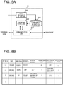
- FIG. 5A is a diagram showing an example of a configuration of the filter 54 in FIG. 3 .
- the filter 54 includes a communication unit 541, a filter information storage unit 543, a transfer control unit 542, and a filter information setting unit 544.
- the communication unit 541 receives a packet and causes a permitted packet to perform voice communication under control of the transfer control unit 542.
- the filter information storage unit 543 stores filter information for controlling discarding and passing of a packet.
- the communication unit 541 extracts an address, a port, and a protocol from a header of a packet received, compares the extracted information with a condition in the filter information storage unit 543, determines rejection and permission of the packet, and notifies the communication unit 541 of the determination result.
- the filter information setting unit 544 sets filter information in the filter information storage section 543.
- the filter information setting unit 544 may set the filter information in the filter information storage unit 543 from a management terminal (not shown) in the data center 50 of FIG. 3 or from a bearer resource correction request from the terminal 1 or the like.
- FIG. 5B shows an example of packet filter information as the configuration of the filter information storage unit 543 of FIG. 5A .
- a type handling of packet conforming to filter condition: passing or discarding
- direction direction of filter evaluation: a direction from a wireless LAN to WAN 2 to WAN 2 is set to UP, from WAN 2 to a wires LAN is set DOWN).
- IP protocol of a packet to be filtered IP protocol of a packet to be filtered
- source IP protocol of a packet to be filtered IP protocol of a packet to be filtered
- transmission port a source port of a packet to be filtered
- destination address Destination IP protocol of a packet to be subjected to packet
- destination port destination port of a packet to be filtered
- a packet from a port 23 (telnet) to the first gateway (GW 1) 51 may be discarded (blocking the telnet port (23)).
- a packet destined for a private IP address of terminal 1 may be discarded.
- a packet destined to a specific destination address from the terminal 1 is discarded. Note that the symbol "*" in FIG. 5B represents arbitrary (any).
- the filter information of FIG. 5B may be set for each terminal (subscriber) by the filter information setting unit 544.
- the filter information may be managed in association with the terminal, and other units such as the transfer control unit 542, the communication unit 541, and the filter information setting unit 544 may be realized by using common codes for a plurality of terminals.
- a user account assigned to a user by the data center 50 may be used for a user of the terminal 1.
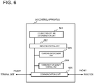
- FIG. 6 Illustrates the controller 56 that controls a charging method, a communication quality (QoS), and the like performed in the vECP 52 of the data center 50 according to whether a network to which the terminal 1 is connected is a wireless LAN, or the base station 10 and the EPC 20 in FIG. 2 .
- QoS communication quality
- the control unit 56 includes a connection destination network determination unit 561 that determines a network to which the terminal is connected, a service control unit 562 that performs setting and control of necessary services according to a network type (wireless LAN, 3G/LTE, etc.) determined by the connection destination network determination unit 561, a charge execution unit 563 that performs charging on a packet basis based on setting information (charge policy) from the service control unit 562, a communication quality control unit 564 that controls communication quality on a packet basis on the basis of setting information (QoS policy) set by the service control unit 562, and a communication unit 565 that exchanges a captured packet with the charging execution unit 563 and is controlled by the communication quality control unit 564.
- a connection destination network determination unit 561 that determines a network to which the terminal is connected
- a service control unit 562 that performs setting and control of necessary services according to a network type (wireless LAN, 3G/LTE, etc.) determined by the connection destination network determination unit 561
- the connection destination network determination unit 561 may be configured to obtain from the terminal, information as to whether the connection destination of the terminal is a non-3GPP access network (wireless LAN access point) or a 3 GPP access network (base station) when the terminal establishes a connection, for example.
- the connection destination network determination unit 561 may obtain connection destination network information of the terminal from radio bearer information managed by MME, or authentication result information at the HSS, 3 GPP AAA server, or the like, when the terminal establishes connection.
- the communication unit 565 stores the received packet in a reception buffer (not shown), and under the control of the communication quality control unit 564, performs priority control such as taking out packets in descending order of priority to send the packets, and performs bandwidth control necessary for bandwidth guarantee or the like of WAN1 and/or WAN 2.
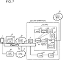
- FIG. 7 is a diagram illustrating an example of the above-described embodiment.
- an IPsec tunnel is established between the ePDG 527 of the vEPC 52 in the data center 50 and the terminal 1.
- the ePDG 527 functions as a VPN gateway and terminates the VPN tunnel.
- the ePDG 527 functions as a VPN gateway to perform the followings:
- the EAP message is transmitted to the ePDG 527 from the terminal 1 using IKEV 2, and relayed to the 3 GPP AAA server 525 of the vEPC 52, where the EAP-SIM / EAP-AKA authentication is performed.
- the ePDG 527 of the vEPC 52 and the PGW 522 are connected via GTP or PMIPv6 tunnel.
- a proxy mobile IP (PMIPv6 tunnel)
- PMIPv6 tunnel a proxy mobile IP
- the ePDG 527 transmits a proxy binding update (Proxy Binding Update) to the PGW 522.
- a proxy binding update Proxy Binding Update
- the PGW 522 includes, for example, a filter 529 having a TFT (Traffic Flow Template) related to an EPS bearer.
- TFT Traffic Flow Template
- setting (addition, modification, deletion, etc.) of a packet filter in a downstream direction from the WAN 2 to the terminal 1 side in the filter 529 may be performed with a Request Bearer Resource Modification message of the bearer resource correction procedure from the terminal 1.
- setting may be performed in connection processing such as an Attach Request message or the like from the terminal 1, or at an occurrence of a predetermined event, or the like.
- the filter 529 may be configured to have a function of performing filtering in an application layer or to have stateful inspection function.
- the filter 529 may be provided with a call rejection list for rejecting incoming calls from the WAN 2 (32).
- P-CSCF Proxy-Call Session Control Function
- Serving-CSCF connected to vEPC 52 may be configured to have content filtering that analyzes contents of voice for blocking and a call rejection list for prohibiting incoming calls from inappropriate numbers.
- the control apparatus 56 is composed of the control apparatus 56 described with reference to FIG. 6 .
- the control apparatus 56 is connected to the PCRF 526, and based on accounting information and QoS policy information notified from the PCRF 526, the control apparatus 56 carries out a control to make a difference in charging control and QoS policy according to a network to which the terminal 1 is connected.
- the control apparatus 56 may be implemented as a PCEF node. Alternatively, the control apparatus 56 may be mounted in the PGW 522.
- the service control unit 562 ( FIG. 6 ) of the control apparatus 56 sets charging and QoS policies according to a network type to which the terminal 1 is connected, based on charging information and QoS policy information notified from the PCRF 526 via a Gx interface, for example.
- the connection destination network determination unit 561 of FIG. 6 may determine,from a result of SIM authentication in the ePDG 527, HSS 524 and 3 GPP AAA 525,that a path from the terminal 1 includes the wireless LAN 40.
- the first and second gateways 51 and 53 may be constituted by routers (edge routers).
- the ePDG 527 and the PGW 522 are implemented as the vEPC 52.
- the ePDG 527 and the PGW 522 may be ePDG 27 and PGW 22 ( FIG. 1 ) of MNO (Mobile Network Operator) that a cloud operator as MVNO (Mobile Virtual Network Operator) has borrowed from the MNO.
- MNO Mobile Network Operator
- MVNO Mobile Virtual Network Operator
- Wi-Fi Registered Trademark
- a VPN 60 IPsec tunnel
- GTP / PMIPv 6 is established between the ePDG 527 and the PGW 522
- connection is made from the PGW 522 to a connection destination via the WAN 2 (32) composed of IMS, for example.
- Wi-Fi registered trademark
- MVNO cloud operator
- the PGW 522 has a function of the second gateway 53 in FIG. 3 .
- the filter 54 in FIG. 7 is the same as the filter 54 described with reference to FIG. 2 and the explanation is omitted.
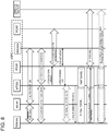
- FIG. 8 is a diagram for explaining an attach processing of the terminal 1 and a sequence for communication connection to a connection destination that connects to the WAN 2 (32) in the system of FIG. 7.
- FIG. 7 illustrates an example of an operation sequence in the terminal 1, WLAN 40 (WLAN AP), ePDG 527, PGW 522, HSS 524 / AAA server 525, PCRF 526, and a connection destination on side of WAN 2 (32) in FIG. 6 .
- the numbers assigned to each sequence operation are sequence numbers for explanation.
- the operation can partially correspond to the operation described with reference to FIG. 4 .
- FIG. 8 it is assumed that the terminal 1 has already been registered in the IMS.
- IPsec IPsec
- a packet in a downlink direction from the WAN 2 (32) side to the terminal 1 is forwarded to the ePDG 527 via the PIMP tunnel to the ePDG 527 by the PGW 522 in the vEPC 52 based on a binding cashe entry, and forwarded from the ePDG 527 to the terminal 1 via the VPN tunnel 60.
- a virtual machine (VM) 571 on a server 57 in the data center 50 connects to a virtual port: A of a virtual switch (vSwitch) 576 via a virtual network interface controller (vNIC) 575, and is connected from a virtual port: B of the virtual switch (vSwitch) 576 to a physical port C of a physical switch (Physical Switch) 58 via a physical NIC (pNIC) 577 and is connected to the physical port C of the physical switch 58 through a physical port D of the physical switch 58 to a network (virtual network) 59 such as a LAN.
- a network virtual network
- the virtual machine 571 includes a guest OS (Operating System) 573 and an application 572 to realize a part or all of functions of the EPC network node (for example, functions of the ePDG 527 in FIG. 7 or functions of other nodes).
- the network 59 is connected, for example, to the first gateway (router) 51 in FIG. 7 .
- a virtual NIC (vNIC), a virtual switch (vSwitch), and the like are provided by a hypervisor 574 which is a virtualization mechanism on the server 57.
- the physical switch 58 may be configured by an L2 (Layer 2) switch and the network 59 may be configured by a virtual network such as a VLAN (Virtual LAN).
- the filter 54 of FIG. 2 may be implemented by the virtual machine 571 of FIG. 12 and the network 55 of FIG. 2 may be configured by a virtual network 59, such as a VLAN.
- a virtual network 59 such as a VLAN.
- management units of NFV Network Functions Virtualization
- NFVO Network Functions Virtualization
- VNF Virtualized Network Function Manager
- FIG. 9 is a diagram illustrating another example embodiment of the present invention.
- the terminal 1 connects via one of a wireless LAN access point 41 provided by a cloud operator possessing the data center 50, a wireless LAN access point 43 provided by another carrier (another carrier) different from the cloud operator 43, a base station 10 of another carrier and an EPC 20 connected with the base station 10 and via the WAN 1 to the data center 50.
- a wireless LAN access point 41 provided by a cloud operator possessing the data center 50
- another carrier another carrier
- a control apparatus (not shown) (56 in FIG. 6 ), depending on a network to which the terminal 1 is connected being which one of:
- the terminal 1 When the terminal 1 connects to the wireless LAN access point 43 of another carrier and connects to the vEPC 52 of the data center 50, predetermined charging for use of the vEPC 52 with setting such as X yen per unit time, for example.
- predetermined charging with setting such as Y yen (Y> X) per unit time.
- QoS control in the vEPC 52 of the data center 50 when the terminal 1 connects to the wireless LAN access point 41 of the cloud operator to connect to the vEPC 52 of the data center 50, quality is set to high.
- quality is set to low.
- quality is set to low or intermediate.
- FIGs. 10A to 10C are diagrams for explaining yet another example embodiment of the present invention.
- the terminal 1 will be described as a smart apparatus such as a smart phone, a tablet terminal, and the like. It is noted that the terminal 1 may be another type of terminal. For example, it may be a conventional mobile phone (feature phone) that is not a smartphone.
- the display unit 11 may be a touch panel combining a display apparatus and a position input apparatus such as a touch pad.
- an icon 111 of a receiver (telephone) mark displayed on a home screen of the display unit 11 in FIG. 10A an application screen is displayed, and when the user taps a phone book icon, a name list is displayed.
- a telephone number 113 is displayed as shown in FIG. 10B .
- a receiver 114 making a telephone call
- a Wi-Fi (registered trademark) telephone 115 are displayed.
- the user makes a call to the other party by selecting either the receiver (making a telephone call) 114 or the Wi-Fi (registered trademark) telephone 115.
- the terminal 1 When the user taps the receiver (calling) 114, the terminal 1 connects to the base station to connect to the calling partner.
- the terminal 1 When the user selects the Wi-Fi (registered trademark) telephone 115, the terminal 1 connects to a Wi-Fi (registered trademark) access point and connects to the calling party with Wi-Fi (registered trademark) -Calling (from a wireless LAN via a security gateway to a carrier's switch).
- Wi-Fi registered trademark
- the terminal 1 connects to a Wi-Fi (registered trademark) access point and connects to the calling party with Wi-Fi (registered trademark) -Calling (from a wireless LAN via a security gateway to a carrier's switch).
- a Wi-Fi (registered trademark) telephone is selected when making a call, but as shown in FIG. 10C , on a network setup screen 116 on the display unit 11, on / off 117 of Wi-Fi (registered trademark) communication, on / off 118 of Wi-Fi (registered trademark) telephone may be set.
- the on / off setting may be a touch type or a slide type.
- SMS by Wi-Fi (registered trademark) -Calling may be displayed as one of selection items.
- the mark of the Wi-Fi (registered trademark) telephone 115 may be variable so as to represent a received radio wave intensity (electric field intensity) from a Wi-Fi (registered trademark) access point.
- the received radio wave intensity (electric field strength) from the Wi-Fi (registered trademark) access point is large, the number of arcs (waves) representing radio waves increases and when the received radio wave intensity (electric field strength) is small, the number of arcs (waves) representing radio waves may be reduced, or a display may be changed.
- FIG. 11A is a diagram schematically illustrating a configuration of the terminal 1 described with reference to FIG. 10A to FIG. 10C .
- the terminal 1 includes a touch panel 1001 for displaying the screen of FIG. 10A to FIG. 10C , a touch panel input and output unit that outputs data and images to the touch panel 1001 and performs position detection of an input to the touch panel 1001, an application (application program) 1003 activated by a tap of the receiver icon 111 ( FIG.
- control unit 1004 that establishes a connection with a wireless LAN or a base station based on the processing result of the application 1003, a communication module (3G/LTE communication module) 1006 that communicates with a base station, a Wi-Fi (registered trademark) communication module (IEEE 802.11 a/b/h/n interface) 1008 and an application 1003 (application program) (3G/LTE communication module) 1006 and an antenna 1007 that communicate with the base station, a control unit 1004 that establishes a connection with a wireless LAN or a base station based on the processing result in the Wi-Fi) communication module (IEEE 802.11 a/b/h/n interface) 1008 and an antenna 1009. Processing of the application 1003, the control unit 1004 may be realized by a program executed by a CPU (Central Processing Unit) (not shown) of the terminal 1.
- CPU Central Processing Unit
- the communication module 1006 or the communication module 1008 may be selected in response to a change in the connection destination network from the terminal 1 or the like at the start of the call, as illustrated in FIG. 10A and FIG. 10B . That is, in a case where the setting information is not stored in the storage unit 1005, the application 1003 determines which one of the telephone (3GPP access network telephone or Wi-Fi (registered trademark) phone) is selected on the touch panel 1001 The control unit 1004 selects the communication module 1006 or the communication module 1008 and communicates with the base station or the Wi-Fi (registered trademark) access point.
- the application 1003 determines which one of the telephone (3GPP access network telephone or Wi-Fi (registered trademark) phone
- the control unit 1004 stores the setting information ( FIG. 10B ) input from the setup screen 116 of FIG. 10C in the storage unit 1005.
- the on/off of the Wi-Fi (registered trademark) telephone may all the time be performed from the setup screen 116 of FIG. 10C .
- Non-Patent Literature 1 is incorporated herein by reference.
- the disclosure of the above Non-Patent Literature 1 is incorporated herein by reference.
- various combinations or selections of various disclosed elements are possible within the scope of the claims of the present invention. That is, it goes without saying that the present invention includes various modifications and modifications that could be made by those skilled in the art according to the entire disclosure including the claims, and technical concepts.
- a communication system including a data center adapted to connect via a first wide area network to a core network connected with a base station and to a wireless LAN (Local Area Network), wherein the data center includes:
- the communication system according to supplementary note 1, wherein in the data center, in accordance with a type of a network to which the terminal connects, the type of the network corresponding to whether the terminal connects to the data center via the base station and the core network and via the first wide area network, or the terminal connects to the data center via the wireless LAN and the first wide area network, and
- the data center includes a VPN apparatus that, in a case where the terminal connects to the data center via the wireless LAN and via the first wide area network, connects to the terminal by a VPN (Virtual Private Network) extending through the first wide area network and the wireless LAN.
- VPN Virtual Private Network
- the filter controls access denial or permission of an incoming call and a message destined to the terminal from the second wide area network side.
- the communication system according to any one of supplementary notes 3 to 6, wherein the VPN apparatus of the data center manages the VPN between the terminal and the VPN apparatus, on a per terminal basis or on a per terminal user basis.
- the terminal comprises means that selects to communicate either via the base station or via the wireless LAN.
- an access point of the wireless LAN includes at least one of an access point provided by an operator of the data center, and an access point provided by another communication carrier.
- a communication apparatus comprising:
- control apparatus variably controls at least one of a charging method and a communication quality service provided to the terminal in the virtual core network
- the communication apparatus comprising a VPN apparatus that, in a case where the terminal connects to the data center via the wireless LAN and via the first wide area network, connects to the terminal by a VPN (Virtual Private Network) extending through the first wide area network and the wireless LAN.
- VPN Virtual Private Network
- the communication apparatus comprising:
- the communication apparatus controls access denial or permission of an incoming call and a message destined to the terminal from the second wide area network side.
- the communication apparatus according to any one of supplementary notes 12 to 14, wherein the terminal communicates from the VPN via the VPN apparatus and the virtual core network and via the second wide area network with a connection destination, and the terminal receives, through the VPN, an incoming call or data destined to the terminal from the second wide area network from the virtual core network and the VPN apparatus in the data center.
- the communication apparatus according to any one of supplementary notes 10 to 15, wherein the VPN apparatus of the data center manages the VPN between the terminal and the VPN apparatus, on a per terminal basis or on a per terminal user basis.
- a communication method by a data center that is adapted to connect to a core network connected with a base station and to a wireless LAN (Local Area Network) through a first wide area network (Wide Area Network),
- the communication method according to supplementary note 17 or 18, wherein in a case where the terminal connects to the data center via the wireless LAN and via the first wide area network, connection between the terminal and the data center by a VPN (Virtual Private Network) extending through the first wide area network and the wireless LAN.
- VPN Virtual Private Network
- the communication method comprising controlling by the filter access denial or permission of an incoming call and a message destined to the terminal from the second wide area network side.
- the communication method comprising the VPN apparatus of the data center managing the VPN between the terminal and the VPN apparatus, on a per terminal basis or on a per terminal user basis.
- a terminal comprising:
- a terminal comprising:
- a terminal comprising:
- the terminal according to any one of supplementary notes 24 to 26, comprising: means that when connecting to a data center via the wireless LAN and the first wide area network, connects between the terminal and the data center with a VPN through the wireless LAN and the first wide area network.
- a program causing a computer arranged in a data center adapted to connect via a first wide area network to a core network connected with a base station and to a wireless LAN (Local Area Network) to execute processing comprising;
- the program according to supplementary note 28 casing the computer to execute processing that variably controls at least one of a charging method and a communication quality service provided to the terminal in the virtual core network,
- the program according to supplementary note 28 or 29, casing the computer to execute processing that in a case where the terminal connects to the data center via the wireless LAN and via the first wide area network, connects to the terminal by a VPN (Virtual Private Network) extending through the first wide area network and the wireless LAN.
- VPN Virtual Private Network
- a program causing a computer included in a terminal to execute processing comprising:
- a program causing a computer included in a terminal to execute processing comprising:
Landscapes
- Engineering & Computer Science (AREA)
- Signal Processing (AREA)
- Computer Networks & Wireless Communication (AREA)
- Computer Security & Cryptography (AREA)
- Business, Economics & Management (AREA)
- Accounting & Taxation (AREA)
- Databases & Information Systems (AREA)
- Mobile Radio Communication Systems (AREA)
- Telephonic Communication Services (AREA)
- Meter Arrangements (AREA)
Priority Applications (2)
| Application Number | Priority Date | Filing Date | Title |
|---|---|---|---|
| EP25220762.6A EP4683355A1 (de) | 2015-08-04 | 2016-08-03 | Kommunikationssystem, kommunikationsvorrichtung, kommunikationsverfahren, endgerät und programm |
| EP20187848.5A EP3754960B1 (de) | 2015-08-04 | 2016-08-03 | Datenzentrum mit virtuellem mobilem core-netzwerk |
Applications Claiming Priority (2)
| Application Number | Priority Date | Filing Date | Title |
|---|---|---|---|
| JP2015154492 | 2015-08-04 | ||
| PCT/JP2016/072782 WO2017022791A1 (ja) | 2015-08-04 | 2016-08-03 | 通信システム、通信装置、通信方法、端末、プログラム |
Related Child Applications (3)
| Application Number | Title | Priority Date | Filing Date |
|---|---|---|---|
| EP20187848.5A Division-Into EP3754960B1 (de) | 2015-08-04 | 2016-08-03 | Datenzentrum mit virtuellem mobilem core-netzwerk |
| EP20187848.5A Division EP3754960B1 (de) | 2015-08-04 | 2016-08-03 | Datenzentrum mit virtuellem mobilem core-netzwerk |
| EP25220762.6A Division EP4683355A1 (de) | 2015-08-04 | 2016-08-03 | Kommunikationssystem, kommunikationsvorrichtung, kommunikationsverfahren, endgerät und programm |
Publications (3)
| Publication Number | Publication Date |
|---|---|
| EP3334136A1 true EP3334136A1 (de) | 2018-06-13 |
| EP3334136A4 EP3334136A4 (de) | 2018-07-04 |
| EP3334136B1 EP3334136B1 (de) | 2020-09-23 |
Family
ID=57943084
Family Applications (3)
| Application Number | Title | Priority Date | Filing Date |
|---|---|---|---|
| EP20187848.5A Active EP3754960B1 (de) | 2015-08-04 | 2016-08-03 | Datenzentrum mit virtuellem mobilem core-netzwerk |
| EP25220762.6A Pending EP4683355A1 (de) | 2015-08-04 | 2016-08-03 | Kommunikationssystem, kommunikationsvorrichtung, kommunikationsverfahren, endgerät und programm |
| EP16833070.2A Active EP3334136B1 (de) | 2015-08-04 | 2016-08-03 | Kommunikationssystem, kommunikationsverfahren, und programm |
Family Applications Before (2)
| Application Number | Title | Priority Date | Filing Date |
|---|---|---|---|
| EP20187848.5A Active EP3754960B1 (de) | 2015-08-04 | 2016-08-03 | Datenzentrum mit virtuellem mobilem core-netzwerk |
| EP25220762.6A Pending EP4683355A1 (de) | 2015-08-04 | 2016-08-03 | Kommunikationssystem, kommunikationsvorrichtung, kommunikationsverfahren, endgerät und programm |
Country Status (4)
| Country | Link |
|---|---|
| US (5) | US10966146B2 (de) |
| EP (3) | EP3754960B1 (de) |
| JP (2) | JP6673356B2 (de) |
| WO (1) | WO2017022791A1 (de) |
Cited By (3)
| Publication number | Priority date | Publication date | Assignee | Title |
|---|---|---|---|---|
| EP3665877A4 (de) * | 2017-10-25 | 2020-08-19 | Huawei Technologies Co., Ltd. | Privates mobiles edge-computing-datenzentrum in einem telekommunikationsnetz |
| WO2021135448A1 (zh) * | 2019-12-31 | 2021-07-08 | 中国银联股份有限公司 | 服务调用方法、装置、设备及介质 |
| EP4362601A4 (de) * | 2021-06-22 | 2025-07-16 | Soracom Inc | Vorrichtung und verfahren zur bereitstellung eines kommunikationsdienstes für den zugriff auf ein ip-netzwerk und programm dafür |
Families Citing this family (80)
| Publication number | Priority date | Publication date | Assignee | Title |
|---|---|---|---|---|
| US10454714B2 (en) | 2013-07-10 | 2019-10-22 | Nicira, Inc. | Method and system of overlay flow control |
| US10749711B2 (en) | 2013-07-10 | 2020-08-18 | Nicira, Inc. | Network-link method useful for a last-mile connectivity in an edge-gateway multipath system |
| US10498652B2 (en) | 2015-04-13 | 2019-12-03 | Nicira, Inc. | Method and system of application-aware routing with crowdsourcing |
| US10135789B2 (en) | 2015-04-13 | 2018-11-20 | Nicira, Inc. | Method and system of establishing a virtual private network in a cloud service for branch networking |
| US10425382B2 (en) | 2015-04-13 | 2019-09-24 | Nicira, Inc. | Method and system of a cloud-based multipath routing protocol |
| CN107360089B (zh) * | 2016-05-10 | 2021-03-19 | 新华三技术有限公司 | 一种路由建立方法、业务数据转换方法及装置 |
| US11121962B2 (en) | 2017-01-31 | 2021-09-14 | Vmware, Inc. | High performance software-defined core network |
| US20200036624A1 (en) | 2017-01-31 | 2020-01-30 | The Mode Group | High performance software-defined core network |
| US11252079B2 (en) | 2017-01-31 | 2022-02-15 | Vmware, Inc. | High performance software-defined core network |
| US11706127B2 (en) | 2017-01-31 | 2023-07-18 | Vmware, Inc. | High performance software-defined core network |
| US20180219765A1 (en) | 2017-01-31 | 2018-08-02 | Waltz Networks | Method and Apparatus for Network Traffic Control Optimization |
| US10992558B1 (en) | 2017-11-06 | 2021-04-27 | Vmware, Inc. | Method and apparatus for distributed data network traffic optimization |
| US10992568B2 (en) | 2017-01-31 | 2021-04-27 | Vmware, Inc. | High performance software-defined core network |
| US10778528B2 (en) | 2017-02-11 | 2020-09-15 | Nicira, Inc. | Method and system of connecting to a multipath hub in a cluster |
| US10798633B2 (en) * | 2017-02-23 | 2020-10-06 | Cisco Technology, Inc. | Heterogeneous access gateway for an information-centric networking environment |
| US10516652B1 (en) * | 2017-02-28 | 2019-12-24 | Amazon Technologies, Inc. | Security association management |
| JP6687564B2 (ja) * | 2017-06-16 | 2020-04-22 | Kddi株式会社 | 通信システム、通信方法 |
| US10523539B2 (en) | 2017-06-22 | 2019-12-31 | Nicira, Inc. | Method and system of resiliency in cloud-delivered SD-WAN |
| US10785195B2 (en) * | 2017-07-31 | 2020-09-22 | Cisco Technology, Inc. | Mobile communications over secure enterprise networks |
| CN109391915B (zh) * | 2017-08-14 | 2021-03-30 | 华为技术有限公司 | 基于cups协议的离线计费话单阈值控制方法及系统 |
| US10959098B2 (en) | 2017-10-02 | 2021-03-23 | Vmware, Inc. | Dynamically specifying multiple public cloud edge nodes to connect to an external multi-computer node |
| US10999100B2 (en) | 2017-10-02 | 2021-05-04 | Vmware, Inc. | Identifying multiple nodes in a virtual network defined over a set of public clouds to connect to an external SAAS provider |
| US11115480B2 (en) | 2017-10-02 | 2021-09-07 | Vmware, Inc. | Layer four optimization for a virtual network defined over public cloud |
| US11089111B2 (en) | 2017-10-02 | 2021-08-10 | Vmware, Inc. | Layer four optimization for a virtual network defined over public cloud |
| US10958479B2 (en) | 2017-10-02 | 2021-03-23 | Vmware, Inc. | Selecting one node from several candidate nodes in several public clouds to establish a virtual network that spans the public clouds |
| US10999165B2 (en) | 2017-10-02 | 2021-05-04 | Vmware, Inc. | Three tiers of SaaS providers for deploying compute and network infrastructure in the public cloud |
| US11223514B2 (en) | 2017-11-09 | 2022-01-11 | Nicira, Inc. | Method and system of a dynamic high-availability mode based on current wide area network connectivity |
| US11533669B2 (en) * | 2019-04-26 | 2022-12-20 | Cisco Technology, Inc. | Enterprise network fabric extension across mobile networks |
| US12395897B2 (en) | 2019-06-17 | 2025-08-19 | Ntt Docomo, Inc. | Communication device and communication method for mobile communication based on quality of service (QoS) |
| US11212238B2 (en) | 2019-08-27 | 2021-12-28 | Vmware, Inc. | Providing recommendations for implementing virtual networks |
| US11611507B2 (en) | 2019-10-28 | 2023-03-21 | Vmware, Inc. | Managing forwarding elements at edge nodes connected to a virtual network |
| CN110933640B (zh) * | 2019-11-18 | 2022-09-16 | 南通大学 | 一种基于虚拟移动蜂窝的智能网联车无缝通信方法 |
| US11394640B2 (en) | 2019-12-12 | 2022-07-19 | Vmware, Inc. | Collecting and analyzing data regarding flows associated with DPI parameters |
| US11489783B2 (en) | 2019-12-12 | 2022-11-01 | Vmware, Inc. | Performing deep packet inspection in a software defined wide area network |
| US11582066B2 (en) | 2019-12-19 | 2023-02-14 | Cisco Technology, Inc. | Techniques for extending a cellular quality of service bearer through an enterprise fabric |
| US11438789B2 (en) | 2020-01-24 | 2022-09-06 | Vmware, Inc. | Computing and using different path quality metrics for different service classes |
| US11245641B2 (en) | 2020-07-02 | 2022-02-08 | Vmware, Inc. | Methods and apparatus for application aware hub clustering techniques for a hyper scale SD-WAN |
| US11709710B2 (en) | 2020-07-30 | 2023-07-25 | Vmware, Inc. | Memory allocator for I/O operations |
| CN115516996B (zh) * | 2020-11-02 | 2025-04-01 | 谷歌有限责任公司 | 虚拟运营商网络 |
| US11575591B2 (en) | 2020-11-17 | 2023-02-07 | Vmware, Inc. | Autonomous distributed forwarding plane traceability based anomaly detection in application traffic for hyper-scale SD-WAN |
| US11575600B2 (en) | 2020-11-24 | 2023-02-07 | Vmware, Inc. | Tunnel-less SD-WAN |
| US11929903B2 (en) | 2020-12-29 | 2024-03-12 | VMware LLC | Emulating packet flows to assess network links for SD-WAN |
| US12218845B2 (en) | 2021-01-18 | 2025-02-04 | VMware LLC | Network-aware load balancing |
| US11792127B2 (en) | 2021-01-18 | 2023-10-17 | Vmware, Inc. | Network-aware load balancing |
| US11979325B2 (en) | 2021-01-28 | 2024-05-07 | VMware LLC | Dynamic SD-WAN hub cluster scaling with machine learning |
| WO2022185984A1 (ja) * | 2021-03-04 | 2022-09-09 | 京セラドキュメントソリューションズ株式会社 | 情報処理装置および情報処理システム |
| US12368676B2 (en) | 2021-04-29 | 2025-07-22 | VMware LLC | Methods for micro-segmentation in SD-WAN for virtual networks |
| US12009987B2 (en) | 2021-05-03 | 2024-06-11 | VMware LLC | Methods to support dynamic transit paths through hub clustering across branches in SD-WAN |
| US11509571B1 (en) | 2021-05-03 | 2022-11-22 | Vmware, Inc. | Cost-based routing mesh for facilitating routing through an SD-WAN |
| US11729065B2 (en) | 2021-05-06 | 2023-08-15 | Vmware, Inc. | Methods for application defined virtual network service among multiple transport in SD-WAN |
| US11489720B1 (en) | 2021-06-18 | 2022-11-01 | Vmware, Inc. | Method and apparatus to evaluate resource elements and public clouds for deploying tenant deployable elements based on harvested performance metrics |
| US12250114B2 (en) | 2021-06-18 | 2025-03-11 | VMware LLC | Method and apparatus for deploying tenant deployable elements across public clouds based on harvested performance metrics of sub-types of resource elements in the public clouds |
| US12015536B2 (en) | 2021-06-18 | 2024-06-18 | VMware LLC | Method and apparatus for deploying tenant deployable elements across public clouds based on harvested performance metrics of types of resource elements in the public clouds |
| JP7076050B1 (ja) | 2021-06-22 | 2022-05-26 | 株式会社ソラコム | Ipネットワークにアクセスするための通信サービスを提供するための装置、方法及びそのためのプログラム |
| JP7076051B1 (ja) | 2021-06-22 | 2022-05-26 | 株式会社ソラコム | Ipネットワークにアクセスするための通信サービスを提供するための装置、方法及びそのためのプログラム |
| US12047282B2 (en) | 2021-07-22 | 2024-07-23 | VMware LLC | Methods for smart bandwidth aggregation based dynamic overlay selection among preferred exits in SD-WAN |
| US12267364B2 (en) | 2021-07-24 | 2025-04-01 | VMware LLC | Network management services in a virtual network |
| US11375005B1 (en) | 2021-07-24 | 2022-06-28 | Vmware, Inc. | High availability solutions for a secure access service edge application |
| US11943146B2 (en) | 2021-10-01 | 2024-03-26 | VMware LLC | Traffic prioritization in SD-WAN |
| CN114173358B (zh) * | 2021-12-09 | 2024-07-23 | 南京邮电大学 | 5g局域网公网系统及其设计方法 |
| CN116266963B (zh) * | 2021-12-17 | 2026-03-10 | 中国电信股份有限公司 | 基于基站网关的数据传输方法、系统、设备及存储介质 |
| US12184557B2 (en) | 2022-01-04 | 2024-12-31 | VMware LLC | Explicit congestion notification in a virtual environment |
| US12507120B2 (en) | 2022-01-12 | 2025-12-23 | Velocloud Networks, Llc | Heterogeneous hub clustering and application policy based automatic node selection for network of clouds |
| US12425395B2 (en) | 2022-01-15 | 2025-09-23 | VMware LLC | Method and system of securely adding an edge device operating in a public network to an SD-WAN |
| US12506678B2 (en) | 2022-01-25 | 2025-12-23 | VMware LLC | Providing DNS service in an SD-WAN |
| US11909815B2 (en) | 2022-06-06 | 2024-02-20 | VMware LLC | Routing based on geolocation costs |
| US12166661B2 (en) | 2022-07-18 | 2024-12-10 | VMware LLC | DNS-based GSLB-aware SD-WAN for low latency SaaS applications |
| US20240028378A1 (en) | 2022-07-20 | 2024-01-25 | Vmware, Inc. | Method for modifying an sd-wan using metric-based heat maps |
| US20240073743A1 (en) | 2022-08-28 | 2024-02-29 | Vmware, Inc. | Dynamic use of multiple wireless network links to connect a vehicle to an sd-wan |
| US12328299B2 (en) * | 2022-09-29 | 2025-06-10 | Rakuten Symphony, Inc. | System, method and non-transitory computer readable medium for an internet-enabled network radio node |
| US12057993B1 (en) | 2023-03-27 | 2024-08-06 | VMware LLC | Identifying and remediating anomalies in a self-healing network |
| US12034587B1 (en) | 2023-03-27 | 2024-07-09 | VMware LLC | Identifying and remediating anomalies in a self-healing network |
| US12425332B2 (en) | 2023-03-27 | 2025-09-23 | VMware LLC | Remediating anomalies in a self-healing network |
| US12507148B2 (en) | 2023-08-16 | 2025-12-23 | Velocloud Networks, Llc | Interconnecting clusters in multi-regional large scale deployments with distributed gateways |
| US12563438B2 (en) | 2023-08-16 | 2026-02-24 | Velocloud Networks, Llc | Distributed gateways for multi-regional large scale deployments |
| US12507153B2 (en) | 2023-08-16 | 2025-12-23 | Velocloud Networks, Llc | Dynamic edge-to-edge across multiple hops in multi-regional large scale deployments with distributed gateways |
| US12261777B2 (en) | 2023-08-16 | 2025-03-25 | VMware LLC | Forwarding packets in multi-regional large scale deployments with distributed gateways |
| US12587468B2 (en) | 2023-08-16 | 2026-03-24 | Velocloud Networks, Llc | Route filtering for clusters in multi-regional large scale deployments with distributed gateways |
| US12355655B2 (en) | 2023-08-16 | 2025-07-08 | VMware LLC | Forwarding packets in multi-regional large scale deployments with distributed gateways |
| US12483968B2 (en) | 2023-08-16 | 2025-11-25 | Velocloud Networks, Llc | Distributed gateways for multi-regional large scale deployments |
Family Cites Families (19)
| Publication number | Priority date | Publication date | Assignee | Title |
|---|---|---|---|---|
| JP4159548B2 (ja) * | 2002-11-13 | 2008-10-01 | 富士通株式会社 | ネットワークアクセス制御システム |
| US20050148321A1 (en) | 2002-11-13 | 2005-07-07 | Yoichiro Igarashi | Network access control system |
| JP4805048B2 (ja) * | 2006-07-21 | 2011-11-02 | ソフトバンクモバイル株式会社 | 携帯端末及びサーバ装置 |
| GB2472755A (en) * | 2008-06-13 | 2011-02-16 | Nortel Networks Ltd | Unifying virtualizations in a core network and wireless access network |
| JP4963687B2 (ja) | 2008-08-04 | 2012-06-27 | Kddi株式会社 | 課金を考慮して局所通信網からセルラ広域通信網へ切り替える再発呼方法、移動端末及びプログラム |
| JP5638877B2 (ja) * | 2010-08-26 | 2014-12-10 | Necパーソナルコンピュータ株式会社 | 通信システム、通信端末、通信方法およびプログラム |
| JP6314971B2 (ja) * | 2012-08-03 | 2018-04-25 | 日本電気株式会社 | 移動端末、通信方法、通信システム、プログラム、情報処理装置、サービス提供方法および配信サーバ |
| TW201807961A (zh) | 2012-09-27 | 2018-03-01 | 內數位專利控股公司 | 在噓擬網路中端對端架構、api框架、發現及存取 |
| US20140259012A1 (en) * | 2013-03-06 | 2014-09-11 | Telefonaktiebolaget L M Ericsson (Publ) | Virtual machine mobility with evolved packet core |
| JP2014195167A (ja) * | 2013-03-28 | 2014-10-09 | Nippon Telegraph & Telephone East Corp | 電話システム及びその方法 |
| US9716996B2 (en) * | 2013-05-21 | 2017-07-25 | Brocade Communications Systems, Inc. | Method and system for selective and secure interaction of BYOD (bring your own device) with enterprise network through mobile wireless networks |
| US9819469B2 (en) | 2013-07-01 | 2017-11-14 | Qualcomm Incorporated | Techniques for enabling quality of service (QoS) on WLAN for traffic related to a bearer on cellular networks |
| US20150124622A1 (en) * | 2013-11-01 | 2015-05-07 | Movik Networks, Inc. | Multi-Interface, Multi-Layer State-full Load Balancer For RAN-Analytics Deployments In Multi-Chassis, Cloud And Virtual Server Environments |
| US9479934B2 (en) * | 2013-12-13 | 2016-10-25 | Parallel Wireless, Inc. | Virtualization of the evolved packet core to create a local EPC |
| CN106062718B (zh) * | 2014-01-17 | 2020-03-03 | 诺基亚通信有限责任两合公司 | 控制包括虚拟化网络功能的通信网络 |
| JP2015154492A (ja) | 2014-02-14 | 2015-08-24 | アバゴ・テクノロジーズ・ジェネラル・アイピー(シンガポール)プライベート・リミテッド | 音響反射器、フレーム、及びカラーを備える音響共振器 |
| US10164871B2 (en) * | 2015-03-27 | 2018-12-25 | Intel IP Corporation | Methods and devices for multi-device link aggregation |
| JP6496423B2 (ja) | 2015-04-22 | 2019-04-03 | 華為技術有限公司Huawei Technologies Co.,Ltd. | サービス割り当て方法及び装置 |
| EP3323258B1 (de) * | 2015-07-10 | 2019-10-30 | Parallel Wireless Inc. | Erweitertes x2-protokoll |
-
2016
- 2016-08-03 EP EP20187848.5A patent/EP3754960B1/de active Active
- 2016-08-03 EP EP25220762.6A patent/EP4683355A1/de active Pending
- 2016-08-03 JP JP2017533105A patent/JP6673356B2/ja active Active
- 2016-08-03 US US15/747,323 patent/US10966146B2/en active Active
- 2016-08-03 EP EP16833070.2A patent/EP3334136B1/de active Active
- 2016-08-03 WO PCT/JP2016/072782 patent/WO2017022791A1/ja not_active Ceased
-
2020
- 2020-03-03 JP JP2020036059A patent/JP6981491B2/ja active Active
-
2021
- 2021-01-12 US US17/147,136 patent/US11743810B2/en active Active
-
2023
- 2023-06-23 US US18/213,292 patent/US12250625B2/en active Active
-
2025
- 2025-02-04 US US19/045,112 patent/US20250184883A1/en active Pending
- 2025-05-09 US US19/203,730 patent/US12464449B2/en active Active
Cited By (4)
| Publication number | Priority date | Publication date | Assignee | Title |
|---|---|---|---|---|
| EP3665877A4 (de) * | 2017-10-25 | 2020-08-19 | Huawei Technologies Co., Ltd. | Privates mobiles edge-computing-datenzentrum in einem telekommunikationsnetz |
| WO2021135448A1 (zh) * | 2019-12-31 | 2021-07-08 | 中国银联股份有限公司 | 服务调用方法、装置、设备及介质 |
| US11677815B2 (en) | 2019-12-31 | 2023-06-13 | China Unionpay Co., Ltd. | Service invoking method, device, apparatus and medium |
| EP4362601A4 (de) * | 2021-06-22 | 2025-07-16 | Soracom Inc | Vorrichtung und verfahren zur bereitstellung eines kommunikationsdienstes für den zugriff auf ein ip-netzwerk und programm dafür |
Also Published As
| Publication number | Publication date |
|---|---|
| US20180213472A1 (en) | 2018-07-26 |
| EP3334136A4 (de) | 2018-07-04 |
| EP3334136B1 (de) | 2020-09-23 |
| US12250625B2 (en) | 2025-03-11 |
| EP3754960A1 (de) | 2020-12-23 |
| JP6673356B2 (ja) | 2020-03-25 |
| JP2020099097A (ja) | 2020-06-25 |
| US20250267567A1 (en) | 2025-08-21 |
| US20250184883A1 (en) | 2025-06-05 |
| US11743810B2 (en) | 2023-08-29 |
| US20230337127A1 (en) | 2023-10-19 |
| US20210136677A1 (en) | 2021-05-06 |
| JP6981491B2 (ja) | 2021-12-15 |
| US12464449B2 (en) | 2025-11-04 |
| EP4683355A1 (de) | 2026-01-21 |
| US10966146B2 (en) | 2021-03-30 |
| EP3754960B1 (de) | 2026-01-28 |
| JPWO2017022791A1 (ja) | 2018-05-24 |
| WO2017022791A1 (ja) | 2017-02-09 |
Similar Documents
| Publication | Publication Date | Title |
|---|---|---|
| US12464449B2 (en) | Communication system, communication apparatus, communication method, terminal, and non-transitory medium | |
| US11870604B2 (en) | Communication system, communication device, communication method, terminal, non-transitory medium for providing secure communication in a network | |
| US10764088B2 (en) | Communication system, communication apparatus, communication method, terminal, non-transitory medium | |
| US11115808B2 (en) | Consolidated control plane routing agent | |
| EP3529968B1 (de) | System und verfahren für knotenauswahl auf der grundlage von ereignisinformationen in der mitte und am ende einer sitzung | |
| CN108029017B (zh) | 通过受管理的公共WLAN接入进行安全wifi呼叫连接的方法 | |
| US9300453B2 (en) | Providing in-line services through radio access network resources under control of a mobile packet core in a network environment | |
| WO2021126649A1 (en) | Techniques for providing a third generation partnership project (3gpp) fabric anchor for an enterprise fabric | |
| CN104137504B (zh) | 访问由3gpp hplmn中的业务传递平台传递的服务的方法和实体 | |
| WO2021126738A1 (en) | Techniques for extending a cellular quality of service bearer through an enterprise fabric | |
| US9215588B2 (en) | System and method for providing selective bearer security in a network environment | |
| US20080219224A1 (en) | System and Method for Providing Secure Mobility and Internet Protocol Security Related Services to a Mobile Node Roaming in a Foreign Network | |
| US20250324260A1 (en) | Service access service edge solution for providing enhanced security for unmanaged devices for mobile networks | |
| WO2025221556A1 (en) | Service access service edge solution for providing enhanced security for unmanaged devices for mobile networks |
Legal Events
| Date | Code | Title | Description |
|---|---|---|---|
| STAA | Information on the status of an ep patent application or granted ep patent |
Free format text: STATUS: THE INTERNATIONAL PUBLICATION HAS BEEN MADE |
|
| PUAI | Public reference made under article 153(3) epc to a published international application that has entered the european phase |
Free format text: ORIGINAL CODE: 0009012 |
|
| STAA | Information on the status of an ep patent application or granted ep patent |
Free format text: STATUS: REQUEST FOR EXAMINATION WAS MADE |
|
| 17P | Request for examination filed |
Effective date: 20180212 |
|
| AK | Designated contracting states |
Kind code of ref document: A1 Designated state(s): AL AT BE BG CH CY CZ DE DK EE ES FI FR GB GR HR HU IE IS IT LI LT LU LV MC MK MT NL NO PL PT RO RS SE SI SK SM TR |
|
| AX | Request for extension of the european patent |
Extension state: BA ME |
|
| A4 | Supplementary search report drawn up and despatched |
Effective date: 20180601 |
|
| RIC1 | Information provided on ipc code assigned before grant |
Ipc: H04W 4/00 20180101ALI20180525BHEP Ipc: H04L 12/903 20130101ALI20180525BHEP Ipc: H04L 12/70 20130101ALI20180525BHEP Ipc: H04W 92/02 20090101ALI20180525BHEP Ipc: H04L 12/66 20060101ALI20180525BHEP Ipc: H04W 4/24 20180101ALI20180525BHEP Ipc: H04W 48/18 20090101ALI20180525BHEP Ipc: H04M 3/00 20060101AFI20180525BHEP Ipc: H04W 88/06 20090101ALI20180525BHEP |
|
| DAV | Request for validation of the european patent (deleted) | ||
| DAX | Request for extension of the european patent (deleted) | ||
| STAA | Information on the status of an ep patent application or granted ep patent |
Free format text: STATUS: EXAMINATION IS IN PROGRESS |
|
| 17Q | First examination report despatched |
Effective date: 20190828 |
|
| GRAP | Despatch of communication of intention to grant a patent |
Free format text: ORIGINAL CODE: EPIDOSNIGR1 |
|
| STAA | Information on the status of an ep patent application or granted ep patent |
Free format text: STATUS: GRANT OF PATENT IS INTENDED |
|
| INTG | Intention to grant announced |
Effective date: 20200330 |
|
| GRAS | Grant fee paid |
Free format text: ORIGINAL CODE: EPIDOSNIGR3 |
|
| GRAA | (expected) grant |
Free format text: ORIGINAL CODE: 0009210 |
|
| STAA | Information on the status of an ep patent application or granted ep patent |
Free format text: STATUS: THE PATENT HAS BEEN GRANTED |
|
| AK | Designated contracting states |
Kind code of ref document: B1 Designated state(s): AL AT BE BG CH CY CZ DE DK EE ES FI FR GB GR HR HU IE IS IT LI LT LU LV MC MK MT NL NO PL PT RO RS SE SI SK SM TR |
|
| REG | Reference to a national code |
Ref country code: GB Ref legal event code: FG4D |
|
| REG | Reference to a national code |
Ref country code: CH Ref legal event code: EP |
|
| REG | Reference to a national code |
Ref country code: DE Ref legal event code: R096 Ref document number: 602016044684 Country of ref document: DE |
|
| REG | Reference to a national code |
Ref country code: IE Ref legal event code: FG4D |
|
| REG | Reference to a national code |
Ref country code: AT Ref legal event code: REF Ref document number: 1317595 Country of ref document: AT Kind code of ref document: T Effective date: 20201015 |
|
| PG25 | Lapsed in a contracting state [announced via postgrant information from national office to epo] |
Ref country code: FI Free format text: LAPSE BECAUSE OF FAILURE TO SUBMIT A TRANSLATION OF THE DESCRIPTION OR TO PAY THE FEE WITHIN THE PRESCRIBED TIME-LIMIT Effective date: 20200923 Ref country code: SE Free format text: LAPSE BECAUSE OF FAILURE TO SUBMIT A TRANSLATION OF THE DESCRIPTION OR TO PAY THE FEE WITHIN THE PRESCRIBED TIME-LIMIT Effective date: 20200923 Ref country code: HR Free format text: LAPSE BECAUSE OF FAILURE TO SUBMIT A TRANSLATION OF THE DESCRIPTION OR TO PAY THE FEE WITHIN THE PRESCRIBED TIME-LIMIT Effective date: 20200923 Ref country code: BG Free format text: LAPSE BECAUSE OF FAILURE TO SUBMIT A TRANSLATION OF THE DESCRIPTION OR TO PAY THE FEE WITHIN THE PRESCRIBED TIME-LIMIT Effective date: 20201223 Ref country code: GR Free format text: LAPSE BECAUSE OF FAILURE TO SUBMIT A TRANSLATION OF THE DESCRIPTION OR TO PAY THE FEE WITHIN THE PRESCRIBED TIME-LIMIT Effective date: 20201224 Ref country code: NO Free format text: LAPSE BECAUSE OF FAILURE TO SUBMIT A TRANSLATION OF THE DESCRIPTION OR TO PAY THE FEE WITHIN THE PRESCRIBED TIME-LIMIT Effective date: 20201223 |
|
| REG | Reference to a national code |
Ref country code: AT Ref legal event code: MK05 Ref document number: 1317595 Country of ref document: AT Kind code of ref document: T Effective date: 20200923 |
|
| PG25 | Lapsed in a contracting state [announced via postgrant information from national office to epo] |
Ref country code: RS Free format text: LAPSE BECAUSE OF FAILURE TO SUBMIT A TRANSLATION OF THE DESCRIPTION OR TO PAY THE FEE WITHIN THE PRESCRIBED TIME-LIMIT Effective date: 20200923 Ref country code: LV Free format text: LAPSE BECAUSE OF FAILURE TO SUBMIT A TRANSLATION OF THE DESCRIPTION OR TO PAY THE FEE WITHIN THE PRESCRIBED TIME-LIMIT Effective date: 20200923 |
|
| REG | Reference to a national code |
Ref country code: NL Ref legal event code: MP Effective date: 20200923 |
|
| REG | Reference to a national code |
Ref country code: LT Ref legal event code: MG4D |
|
| PG25 | Lapsed in a contracting state [announced via postgrant information from national office to epo] |
Ref country code: EE Free format text: LAPSE BECAUSE OF FAILURE TO SUBMIT A TRANSLATION OF THE DESCRIPTION OR TO PAY THE FEE WITHIN THE PRESCRIBED TIME-LIMIT Effective date: 20200923 Ref country code: SM Free format text: LAPSE BECAUSE OF FAILURE TO SUBMIT A TRANSLATION OF THE DESCRIPTION OR TO PAY THE FEE WITHIN THE PRESCRIBED TIME-LIMIT Effective date: 20200923 Ref country code: LT Free format text: LAPSE BECAUSE OF FAILURE TO SUBMIT A TRANSLATION OF THE DESCRIPTION OR TO PAY THE FEE WITHIN THE PRESCRIBED TIME-LIMIT Effective date: 20200923 Ref country code: RO Free format text: LAPSE BECAUSE OF FAILURE TO SUBMIT A TRANSLATION OF THE DESCRIPTION OR TO PAY THE FEE WITHIN THE PRESCRIBED TIME-LIMIT Effective date: 20200923 Ref country code: PT Free format text: LAPSE BECAUSE OF FAILURE TO SUBMIT A TRANSLATION OF THE DESCRIPTION OR TO PAY THE FEE WITHIN THE PRESCRIBED TIME-LIMIT Effective date: 20210125 Ref country code: CZ Free format text: LAPSE BECAUSE OF FAILURE TO SUBMIT A TRANSLATION OF THE DESCRIPTION OR TO PAY THE FEE WITHIN THE PRESCRIBED TIME-LIMIT Effective date: 20200923 |
|
| PG25 | Lapsed in a contracting state [announced via postgrant information from national office to epo] |
Ref country code: AL Free format text: LAPSE BECAUSE OF FAILURE TO SUBMIT A TRANSLATION OF THE DESCRIPTION OR TO PAY THE FEE WITHIN THE PRESCRIBED TIME-LIMIT Effective date: 20200923 Ref country code: AT Free format text: LAPSE BECAUSE OF FAILURE TO SUBMIT A TRANSLATION OF THE DESCRIPTION OR TO PAY THE FEE WITHIN THE PRESCRIBED TIME-LIMIT Effective date: 20200923 Ref country code: ES Free format text: LAPSE BECAUSE OF FAILURE TO SUBMIT A TRANSLATION OF THE DESCRIPTION OR TO PAY THE FEE WITHIN THE PRESCRIBED TIME-LIMIT Effective date: 20200923 Ref country code: IS Free format text: LAPSE BECAUSE OF FAILURE TO SUBMIT A TRANSLATION OF THE DESCRIPTION OR TO PAY THE FEE WITHIN THE PRESCRIBED TIME-LIMIT Effective date: 20210123 Ref country code: PL Free format text: LAPSE BECAUSE OF FAILURE TO SUBMIT A TRANSLATION OF THE DESCRIPTION OR TO PAY THE FEE WITHIN THE PRESCRIBED TIME-LIMIT Effective date: 20200923 |
|
| REG | Reference to a national code |
Ref country code: DE Ref legal event code: R097 Ref document number: 602016044684 Country of ref document: DE |
|
| PG25 | Lapsed in a contracting state [announced via postgrant information from national office to epo] |
Ref country code: SK Free format text: LAPSE BECAUSE OF FAILURE TO SUBMIT A TRANSLATION OF THE DESCRIPTION OR TO PAY THE FEE WITHIN THE PRESCRIBED TIME-LIMIT Effective date: 20200923 |
|
| PLBE | No opposition filed within time limit |
Free format text: ORIGINAL CODE: 0009261 |
|
| STAA | Information on the status of an ep patent application or granted ep patent |
Free format text: STATUS: NO OPPOSITION FILED WITHIN TIME LIMIT |
|
| PG25 | Lapsed in a contracting state [announced via postgrant information from national office to epo] |
Ref country code: SI Free format text: LAPSE BECAUSE OF FAILURE TO SUBMIT A TRANSLATION OF THE DESCRIPTION OR TO PAY THE FEE WITHIN THE PRESCRIBED TIME-LIMIT Effective date: 20200923 Ref country code: DK Free format text: LAPSE BECAUSE OF FAILURE TO SUBMIT A TRANSLATION OF THE DESCRIPTION OR TO PAY THE FEE WITHIN THE PRESCRIBED TIME-LIMIT Effective date: 20200923 |
|
| 26N | No opposition filed |
Effective date: 20210624 |
|
| PG25 | Lapsed in a contracting state [announced via postgrant information from national office to epo] |
Ref country code: IT Free format text: LAPSE BECAUSE OF FAILURE TO SUBMIT A TRANSLATION OF THE DESCRIPTION OR TO PAY THE FEE WITHIN THE PRESCRIBED TIME-LIMIT Effective date: 20200923 |
|
| REG | Reference to a national code |
Ref country code: CH Ref legal event code: PL |
|
| PG25 | Lapsed in a contracting state [announced via postgrant information from national office to epo] |
Ref country code: MC Free format text: LAPSE BECAUSE OF FAILURE TO SUBMIT A TRANSLATION OF THE DESCRIPTION OR TO PAY THE FEE WITHIN THE PRESCRIBED TIME-LIMIT Effective date: 20200923 |
|
| REG | Reference to a national code |
Ref country code: BE Ref legal event code: MM Effective date: 20210831 |
|
| PG25 | Lapsed in a contracting state [announced via postgrant information from national office to epo] |
Ref country code: LI Free format text: LAPSE BECAUSE OF NON-PAYMENT OF DUE FEES Effective date: 20210831 Ref country code: CH Free format text: LAPSE BECAUSE OF NON-PAYMENT OF DUE FEES Effective date: 20210831 |
|
| PG25 | Lapsed in a contracting state [announced via postgrant information from national office to epo] |
Ref country code: LU Free format text: LAPSE BECAUSE OF NON-PAYMENT OF DUE FEES Effective date: 20210803 |
|
| PG25 | Lapsed in a contracting state [announced via postgrant information from national office to epo] |
Ref country code: IE Free format text: LAPSE BECAUSE OF NON-PAYMENT OF DUE FEES Effective date: 20210803 Ref country code: FR Free format text: LAPSE BECAUSE OF NON-PAYMENT OF DUE FEES Effective date: 20210831 Ref country code: BE Free format text: LAPSE BECAUSE OF NON-PAYMENT OF DUE FEES Effective date: 20210831 |
|
| PG25 | Lapsed in a contracting state [announced via postgrant information from national office to epo] |
Ref country code: HU Free format text: LAPSE BECAUSE OF FAILURE TO SUBMIT A TRANSLATION OF THE DESCRIPTION OR TO PAY THE FEE WITHIN THE PRESCRIBED TIME-LIMIT; INVALID AB INITIO Effective date: 20160803 |
|
| PG25 | Lapsed in a contracting state [announced via postgrant information from national office to epo] |
Ref country code: NL Free format text: LAPSE BECAUSE OF NON-PAYMENT OF DUE FEES Effective date: 20200923 Ref country code: CY Free format text: LAPSE BECAUSE OF FAILURE TO SUBMIT A TRANSLATION OF THE DESCRIPTION OR TO PAY THE FEE WITHIN THE PRESCRIBED TIME-LIMIT Effective date: 20200923 |
|
| PG25 | Lapsed in a contracting state [announced via postgrant information from national office to epo] |
Ref country code: MK Free format text: LAPSE BECAUSE OF FAILURE TO SUBMIT A TRANSLATION OF THE DESCRIPTION OR TO PAY THE FEE WITHIN THE PRESCRIBED TIME-LIMIT Effective date: 20200923 |
|
| PG25 | Lapsed in a contracting state [announced via postgrant information from national office to epo] |
Ref country code: TR Free format text: LAPSE BECAUSE OF FAILURE TO SUBMIT A TRANSLATION OF THE DESCRIPTION OR TO PAY THE FEE WITHIN THE PRESCRIBED TIME-LIMIT Effective date: 20200923 |
|
| PG25 | Lapsed in a contracting state [announced via postgrant information from national office to epo] |
Ref country code: MT Free format text: LAPSE BECAUSE OF FAILURE TO SUBMIT A TRANSLATION OF THE DESCRIPTION OR TO PAY THE FEE WITHIN THE PRESCRIBED TIME-LIMIT Effective date: 20200923 |
|
| PGFP | Annual fee paid to national office [announced via postgrant information from national office to epo] |
Ref country code: DE Payment date: 20250820 Year of fee payment: 10 |
|
| PGFP | Annual fee paid to national office [announced via postgrant information from national office to epo] |
Ref country code: GB Payment date: 20250821 Year of fee payment: 10 |