EP3334002A1 - Battery charging station with module port - Google Patents
Battery charging station with module port Download PDFInfo
- Publication number
- EP3334002A1 EP3334002A1 EP17204954.6A EP17204954A EP3334002A1 EP 3334002 A1 EP3334002 A1 EP 3334002A1 EP 17204954 A EP17204954 A EP 17204954A EP 3334002 A1 EP3334002 A1 EP 3334002A1
- Authority
- EP
- European Patent Office
- Prior art keywords
- accessory device
- charger
- port
- accessory
- power
- Prior art date
- Legal status (The legal status is an assumption and is not a legal conclusion. Google has not performed a legal analysis and makes no representation as to the accuracy of the status listed.)
- Withdrawn
Links
Images


Classifications
-
- G—PHYSICS
- G08—SIGNALLING
- G08C—TRANSMISSION SYSTEMS FOR MEASURED VALUES, CONTROL OR SIMILAR SIGNALS
- G08C17/00—Arrangements for transmitting signals characterised by the use of a wireless electrical link
- G08C17/02—Arrangements for transmitting signals characterised by the use of a wireless electrical link using a radio link
-
- B—PERFORMING OPERATIONS; TRANSPORTING
- B60—VEHICLES IN GENERAL
- B60L—PROPULSION OF ELECTRICALLY-PROPELLED VEHICLES; SUPPLYING ELECTRIC POWER FOR AUXILIARY EQUIPMENT OF ELECTRICALLY-PROPELLED VEHICLES; ELECTRODYNAMIC BRAKE SYSTEMS FOR VEHICLES IN GENERAL; MAGNETIC SUSPENSION OR LEVITATION FOR VEHICLES; MONITORING OPERATING VARIABLES OF ELECTRICALLY-PROPELLED VEHICLES; ELECTRIC SAFETY DEVICES FOR ELECTRICALLY-PROPELLED VEHICLES
- B60L53/00—Methods of charging batteries, specially adapted for electric vehicles; Charging stations or on-board charging equipment therefor; Exchange of energy storage elements in electric vehicles
- B60L53/30—Constructional details of charging stations
-
- E—FIXED CONSTRUCTIONS
- E05—LOCKS; KEYS; WINDOW OR DOOR FITTINGS; SAFES
- E05F—DEVICES FOR MOVING WINGS INTO OPEN OR CLOSED POSITION; CHECKS FOR WINGS; WING FITTINGS NOT OTHERWISE PROVIDED FOR, CONCERNED WITH THE FUNCTIONING OF THE WING
- E05F15/00—Power-operated mechanisms for wings
- E05F15/60—Power-operated mechanisms for wings using electrical actuators
- E05F15/603—Power-operated mechanisms for wings using electrical actuators using rotary electromotors
- E05F15/665—Power-operated mechanisms for wings using electrical actuators using rotary electromotors for vertically-sliding wings
- E05F15/668—Power-operated mechanisms for wings using electrical actuators using rotary electromotors for vertically-sliding wings for overhead wings
- E05F15/681—Power-operated mechanisms for wings using electrical actuators using rotary electromotors for vertically-sliding wings for overhead wings operated by flexible elongated pulling elements, e.g. belts
-
- G—PHYSICS
- G07—CHECKING-DEVICES
- G07C—TIME OR ATTENDANCE REGISTERS; REGISTERING OR INDICATING THE WORKING OF MACHINES; GENERATING RANDOM NUMBERS; VOTING OR LOTTERY APPARATUS; ARRANGEMENTS, SYSTEMS OR APPARATUS FOR CHECKING NOT PROVIDED FOR ELSEWHERE
- G07C9/00—Individual registration on entry or exit
- G07C9/00174—Electronically operated locks; Circuits therefor; Nonmechanical keys therefor, e.g. passive or active electrical keys or other data carriers without mechanical keys
- G07C9/00896—Electronically operated locks; Circuits therefor; Nonmechanical keys therefor, e.g. passive or active electrical keys or other data carriers without mechanical keys specially adapted for particular uses
-
- H—ELECTRICITY
- H02—GENERATION; CONVERSION OR DISTRIBUTION OF ELECTRIC POWER
- H02J—CIRCUIT ARRANGEMENTS OR SYSTEMS FOR SUPPLYING OR DISTRIBUTING ELECTRIC POWER; SYSTEMS FOR STORING ELECTRIC ENERGY
- H02J7/00—Circuit arrangements for charging or depolarising batteries or for supplying loads from batteries
- H02J7/0042—Circuit arrangements for charging or depolarising batteries or for supplying loads from batteries characterised by the mechanical construction
-
- H—ELECTRICITY
- H05—ELECTRIC TECHNIQUES NOT OTHERWISE PROVIDED FOR
- H05K—PRINTED CIRCUITS; CASINGS OR CONSTRUCTIONAL DETAILS OF ELECTRIC APPARATUS; MANUFACTURE OF ASSEMBLAGES OF ELECTRICAL COMPONENTS
- H05K5/00—Casings, cabinets or drawers for electric apparatus
- H05K5/02—Details
- H05K5/0217—Mechanical details of casings
- H05K5/0221—Locks; Latches
-
- H—ELECTRICITY
- H05—ELECTRIC TECHNIQUES NOT OTHERWISE PROVIDED FOR
- H05K—PRINTED CIRCUITS; CASINGS OR CONSTRUCTIONAL DETAILS OF ELECTRIC APPARATUS; MANUFACTURE OF ASSEMBLAGES OF ELECTRICAL COMPONENTS
- H05K5/00—Casings, cabinets or drawers for electric apparatus
- H05K5/02—Details
- H05K5/0247—Electrical details of casings, e.g. terminals, passages for cables or wiring
-
- E—FIXED CONSTRUCTIONS
- E05—LOCKS; KEYS; WINDOW OR DOOR FITTINGS; SAFES
- E05F—DEVICES FOR MOVING WINGS INTO OPEN OR CLOSED POSITION; CHECKS FOR WINGS; WING FITTINGS NOT OTHERWISE PROVIDED FOR, CONCERNED WITH THE FUNCTIONING OF THE WING
- E05F15/00—Power-operated mechanisms for wings
- E05F15/60—Power-operated mechanisms for wings using electrical actuators
- E05F15/603—Power-operated mechanisms for wings using electrical actuators using rotary electromotors
- E05F15/665—Power-operated mechanisms for wings using electrical actuators using rotary electromotors for vertically-sliding wings
- E05F15/668—Power-operated mechanisms for wings using electrical actuators using rotary electromotors for vertically-sliding wings for overhead wings
- E05F15/681—Power-operated mechanisms for wings using electrical actuators using rotary electromotors for vertically-sliding wings for overhead wings operated by flexible elongated pulling elements, e.g. belts
- E05F15/686—Power-operated mechanisms for wings using electrical actuators using rotary electromotors for vertically-sliding wings for overhead wings operated by flexible elongated pulling elements, e.g. belts by cables or ropes
-
- E—FIXED CONSTRUCTIONS
- E05—LOCKS; KEYS; WINDOW OR DOOR FITTINGS; SAFES
- E05F—DEVICES FOR MOVING WINGS INTO OPEN OR CLOSED POSITION; CHECKS FOR WINGS; WING FITTINGS NOT OTHERWISE PROVIDED FOR, CONCERNED WITH THE FUNCTIONING OF THE WING
- E05F15/00—Power-operated mechanisms for wings
- E05F15/70—Power-operated mechanisms for wings with automatic actuation
- E05F15/77—Power-operated mechanisms for wings with automatic actuation using wireless control
-
- E—FIXED CONSTRUCTIONS
- E05—LOCKS; KEYS; WINDOW OR DOOR FITTINGS; SAFES
- E05F—DEVICES FOR MOVING WINGS INTO OPEN OR CLOSED POSITION; CHECKS FOR WINGS; WING FITTINGS NOT OTHERWISE PROVIDED FOR, CONCERNED WITH THE FUNCTIONING OF THE WING
- E05F15/00—Power-operated mechanisms for wings
- E05F15/40—Safety devices, e.g. detection of obstructions or end positions
- E05F15/42—Detection using safety edges
- E05F15/43—Detection using safety edges responsive to disruption of energy beams, e.g. light or sound
- E05F2015/434—Detection using safety edges responsive to disruption of energy beams, e.g. light or sound with optical sensors
- E05F2015/435—Detection using safety edges responsive to disruption of energy beams, e.g. light or sound with optical sensors by interruption of the beam
- E05F2015/436—Detection using safety edges responsive to disruption of energy beams, e.g. light or sound with optical sensors by interruption of the beam the beam being parallel to the wing edge
-
- E—FIXED CONSTRUCTIONS
- E05—LOCKS; KEYS; WINDOW OR DOOR FITTINGS; SAFES
- E05Y—INDEXING SCHEME RELATING TO HINGES OR OTHER SUSPENSION DEVICES FOR DOORS, WINDOWS OR WINGS AND DEVICES FOR MOVING WINGS INTO OPEN OR CLOSED POSITION, CHECKS FOR WINGS AND WING FITTINGS NOT OTHERWISE PROVIDED FOR, CONCERNED WITH THE FUNCTIONING OF THE WING
- E05Y2201/00—Constructional elements; Accessories therefore
- E05Y2201/20—Brakes; Disengaging means, e.g. clutches; Holders, e.g. locks; Stops; Accessories therefore
- E05Y2201/214—Disengaging means
-
- E—FIXED CONSTRUCTIONS
- E05—LOCKS; KEYS; WINDOW OR DOOR FITTINGS; SAFES
- E05Y—INDEXING SCHEME RELATING TO HINGES OR OTHER SUSPENSION DEVICES FOR DOORS, WINDOWS OR WINGS AND DEVICES FOR MOVING WINGS INTO OPEN OR CLOSED POSITION, CHECKS FOR WINGS AND WING FITTINGS NOT OTHERWISE PROVIDED FOR, CONCERNED WITH THE FUNCTIONING OF THE WING
- E05Y2400/00—Electronic control; Power supply; Power or signal transmission; User interfaces
- E05Y2400/60—Power supply; Power or signal transmission
- E05Y2400/61—Power supply
- E05Y2400/612—Batteries
- E05Y2400/614—Batteries charging thereof
-
- E—FIXED CONSTRUCTIONS
- E05—LOCKS; KEYS; WINDOW OR DOOR FITTINGS; SAFES
- E05Y—INDEXING SCHEME RELATING TO HINGES OR OTHER SUSPENSION DEVICES FOR DOORS, WINDOWS OR WINGS AND DEVICES FOR MOVING WINGS INTO OPEN OR CLOSED POSITION, CHECKS FOR WINGS AND WING FITTINGS NOT OTHERWISE PROVIDED FOR, CONCERNED WITH THE FUNCTIONING OF THE WING
- E05Y2400/00—Electronic control; Power supply; Power or signal transmission; User interfaces
- E05Y2400/60—Power supply; Power or signal transmission
- E05Y2400/65—Power or signal transmission
-
- E—FIXED CONSTRUCTIONS
- E05—LOCKS; KEYS; WINDOW OR DOOR FITTINGS; SAFES
- E05Y—INDEXING SCHEME RELATING TO HINGES OR OTHER SUSPENSION DEVICES FOR DOORS, WINDOWS OR WINGS AND DEVICES FOR MOVING WINGS INTO OPEN OR CLOSED POSITION, CHECKS FOR WINGS AND WING FITTINGS NOT OTHERWISE PROVIDED FOR, CONCERNED WITH THE FUNCTIONING OF THE WING
- E05Y2400/00—Electronic control; Power supply; Power or signal transmission; User interfaces
- E05Y2400/80—User interfaces
-
- E—FIXED CONSTRUCTIONS
- E05—LOCKS; KEYS; WINDOW OR DOOR FITTINGS; SAFES
- E05Y—INDEXING SCHEME RELATING TO HINGES OR OTHER SUSPENSION DEVICES FOR DOORS, WINDOWS OR WINGS AND DEVICES FOR MOVING WINGS INTO OPEN OR CLOSED POSITION, CHECKS FOR WINGS AND WING FITTINGS NOT OTHERWISE PROVIDED FOR, CONCERNED WITH THE FUNCTIONING OF THE WING
- E05Y2800/00—Details, accessories and auxiliary operations not otherwise provided for
- E05Y2800/10—Additional functions
- E05Y2800/106—Lighting
-
- E—FIXED CONSTRUCTIONS
- E05—LOCKS; KEYS; WINDOW OR DOOR FITTINGS; SAFES
- E05Y—INDEXING SCHEME RELATING TO HINGES OR OTHER SUSPENSION DEVICES FOR DOORS, WINDOWS OR WINGS AND DEVICES FOR MOVING WINGS INTO OPEN OR CLOSED POSITION, CHECKS FOR WINGS AND WING FITTINGS NOT OTHERWISE PROVIDED FOR, CONCERNED WITH THE FUNCTIONING OF THE WING
- E05Y2800/00—Details, accessories and auxiliary operations not otherwise provided for
- E05Y2800/20—Combinations of elements
-
- E—FIXED CONSTRUCTIONS
- E05—LOCKS; KEYS; WINDOW OR DOOR FITTINGS; SAFES
- E05Y—INDEXING SCHEME RELATING TO HINGES OR OTHER SUSPENSION DEVICES FOR DOORS, WINDOWS OR WINGS AND DEVICES FOR MOVING WINGS INTO OPEN OR CLOSED POSITION, CHECKS FOR WINGS AND WING FITTINGS NOT OTHERWISE PROVIDED FOR, CONCERNED WITH THE FUNCTIONING OF THE WING
- E05Y2800/00—Details, accessories and auxiliary operations not otherwise provided for
- E05Y2800/72—Sets of mutually exchangeable elements
-
- E—FIXED CONSTRUCTIONS
- E05—LOCKS; KEYS; WINDOW OR DOOR FITTINGS; SAFES
- E05Y—INDEXING SCHEME RELATING TO HINGES OR OTHER SUSPENSION DEVICES FOR DOORS, WINDOWS OR WINGS AND DEVICES FOR MOVING WINGS INTO OPEN OR CLOSED POSITION, CHECKS FOR WINGS AND WING FITTINGS NOT OTHERWISE PROVIDED FOR, CONCERNED WITH THE FUNCTIONING OF THE WING
- E05Y2900/00—Application of doors, windows, wings or fittings thereof
- E05Y2900/10—Application of doors, windows, wings or fittings thereof for buildings or parts thereof
- E05Y2900/106—Application of doors, windows, wings or fittings thereof for buildings or parts thereof for garages
-
- G—PHYSICS
- G07—CHECKING-DEVICES
- G07C—TIME OR ATTENDANCE REGISTERS; REGISTERING OR INDICATING THE WORKING OF MACHINES; GENERATING RANDOM NUMBERS; VOTING OR LOTTERY APPARATUS; ARRANGEMENTS, SYSTEMS OR APPARATUS FOR CHECKING NOT PROVIDED FOR ELSEWHERE
- G07C9/00—Individual registration on entry or exit
- G07C9/00174—Electronically operated locks; Circuits therefor; Nonmechanical keys therefor, e.g. passive or active electrical keys or other data carriers without mechanical keys
- G07C9/00896—Electronically operated locks; Circuits therefor; Nonmechanical keys therefor, e.g. passive or active electrical keys or other data carriers without mechanical keys specially adapted for particular uses
- G07C2009/00928—Electronically operated locks; Circuits therefor; Nonmechanical keys therefor, e.g. passive or active electrical keys or other data carriers without mechanical keys specially adapted for particular uses for garage doors
-
- H—ELECTRICITY
- H02—GENERATION; CONVERSION OR DISTRIBUTION OF ELECTRIC POWER
- H02J—CIRCUIT ARRANGEMENTS OR SYSTEMS FOR SUPPLYING OR DISTRIBUTING ELECTRIC POWER; SYSTEMS FOR STORING ELECTRIC ENERGY
- H02J7/00—Circuit arrangements for charging or depolarising batteries or for supplying loads from batteries
- H02J7/00032—Circuit arrangements for charging or depolarising batteries or for supplying loads from batteries characterised by data exchange
- H02J7/00034—Charger exchanging data with an electronic device, i.e. telephone, whose internal battery is under charge
-
- H—ELECTRICITY
- H02—GENERATION; CONVERSION OR DISTRIBUTION OF ELECTRIC POWER
- H02J—CIRCUIT ARRANGEMENTS OR SYSTEMS FOR SUPPLYING OR DISTRIBUTING ELECTRIC POWER; SYSTEMS FOR STORING ELECTRIC ENERGY
- H02J7/00—Circuit arrangements for charging or depolarising batteries or for supplying loads from batteries
- H02J7/00032—Circuit arrangements for charging or depolarising batteries or for supplying loads from batteries characterised by data exchange
- H02J7/00045—Authentication, i.e. circuits for checking compatibility between one component, e.g. a battery or a battery charger, and another component, e.g. a power source
-
- H—ELECTRICITY
- H02—GENERATION; CONVERSION OR DISTRIBUTION OF ELECTRIC POWER
- H02J—CIRCUIT ARRANGEMENTS OR SYSTEMS FOR SUPPLYING OR DISTRIBUTING ELECTRIC POWER; SYSTEMS FOR STORING ELECTRIC ENERGY
- H02J7/00—Circuit arrangements for charging or depolarising batteries or for supplying loads from batteries
- H02J7/02—Circuit arrangements for charging or depolarising batteries or for supplying loads from batteries for charging batteries from ac mains by converters
-
- Y—GENERAL TAGGING OF NEW TECHNOLOGICAL DEVELOPMENTS; GENERAL TAGGING OF CROSS-SECTIONAL TECHNOLOGIES SPANNING OVER SEVERAL SECTIONS OF THE IPC; TECHNICAL SUBJECTS COVERED BY FORMER USPC CROSS-REFERENCE ART COLLECTIONS [XRACs] AND DIGESTS
- Y02—TECHNOLOGIES OR APPLICATIONS FOR MITIGATION OR ADAPTATION AGAINST CLIMATE CHANGE
- Y02T—CLIMATE CHANGE MITIGATION TECHNOLOGIES RELATED TO TRANSPORTATION
- Y02T90/00—Enabling technologies or technologies with a potential or indirect contribution to GHG emissions mitigation
- Y02T90/10—Technologies relating to charging of electric vehicles
- Y02T90/12—Electric charging stations
-
- Y—GENERAL TAGGING OF NEW TECHNOLOGICAL DEVELOPMENTS; GENERAL TAGGING OF CROSS-SECTIONAL TECHNOLOGIES SPANNING OVER SEVERAL SECTIONS OF THE IPC; TECHNICAL SUBJECTS COVERED BY FORMER USPC CROSS-REFERENCE ART COLLECTIONS [XRACs] AND DIGESTS
- Y02—TECHNOLOGIES OR APPLICATIONS FOR MITIGATION OR ADAPTATION AGAINST CLIMATE CHANGE
- Y02T—CLIMATE CHANGE MITIGATION TECHNOLOGIES RELATED TO TRANSPORTATION
- Y02T90/00—Enabling technologies or technologies with a potential or indirect contribution to GHG emissions mitigation
- Y02T90/10—Technologies relating to charging of electric vehicles
- Y02T90/14—Plug-in electric vehicles
Definitions
- the present invention relates to a battery charging device, and more particularly to a battery charging device including electromechanical ports for accessory devices.
- the present invention provides, in one aspect, an accessory device system including an accessory device, a garage door opener including a first accessory device port configured to couple to the accessory device and provide power to the accessory device via the first accessory device port, and a charger.
- the charger includes a second accessory device port configured to couple to the accessory device, and a battery receiving portion configured to be selectively coupled to a battery pack and to charge the battery pack.
- the charger is configured to provide power to the first accessory device via the second accessory device port.
- the present invention provides, in one aspect, a method of operating an accessory device system including a garage door opener, a charger, and an accessory device.
- the method includes receiving, by a first accessory device port on the garage door opener, the accessory device.
- the garage door opener provides power to the accessory device via the first accessory device port.
- the first accessory device port then disconnects from the accessory device and the accessory device is received by a second accessory device port on the charger.
- the charger then provides power to the accessory device via the second accessory device port.
- the present invention provides, in one aspect, a method of operating an accessory device system including an accessory device.
- the method includes receiving the accessory device by an accessory device port on a charger that is portable and non-motorized.
- the charger provides power to the accessory device via the accessory device port and receives via the identity and status data from the accessory device.
- An electronic controller of the charger having a wireless transceiver sends the identity and status data regarding the accessory device to a peripheral device and receives settings data regarding the accessory device from the peripheral device.
- the charger provides the settings data to the accessory device to control the accessory device.
- an accessory device system comprising: an accessory device; a garage door opener including a first accessory device port configured to couple to the accessory device and provide power to the accessory device via the first accessory device port; and a charger including a second accessory device port configured to couple to the accessory device, and a battery receiving portion configured to be selectively coupled to a battery pack and to provide charging power to the battery pack, wherein the charger is configured to provide power to the accessory device via the second accessory device port.
- the battery pack may be a power tool battery pack having a battery cell with at least one selected from the group consisting of nickel cadmium chemistry and lithium ion chemistry.
- the charger may further include an electronic controller having a wireless transceiver and configured to: communicate with a peripheral device to one or more of provide identity and status information regarding the accessory device and to receive settings information to control the accessory device, receive the identity and status information from the accessory device, and provide the settings information to the accessory device to control the accessory device.
- an electronic controller having a wireless transceiver and configured to: communicate with a peripheral device to one or more of provide identity and status information regarding the accessory device and to receive settings information to control the accessory device, receive the identity and status information from the accessory device, and provide the settings information to the accessory device to control the accessory device.
- the charger may further include an AC outlet port and a DC outlet port, or the charger may further include a third accessory device port configured to couple to a second accessory device, and the charger may be configured to provide power to the second accessory device via the third accessory device port.
- the charger may further include an electronic controller having a wireless transceiver and configured to: communicate with a peripheral device to one or more of provide identity and status information regarding the accessory device and the second accessory device and to receive settings information to control the accessory device and the second accessory device, receive the identity and status information from the accessory device and the second accessory device, and provide the settings information to the accessory device and second accessory device to control the accessory device and the second accessory device.
- an electronic controller having a wireless transceiver and configured to: communicate with a peripheral device to one or more of provide identity and status information regarding the accessory device and the second accessory device and to receive settings information to control the accessory device and the second accessory device, receive the identity and status information from the accessory device and the second accessory device, and provide the settings information to the accessory device and second accessory device to control the accessory device and the second accessory device.
- the accessory device may be at least one selected from the group consisting of a wireless speaker, a fan, or a light, or the accessory device may be a first accessory device and the system further comprises a second accessory device configured to couple to the first accessory device port and to the second accessory device port.
- Another embodiment provides a method of operating an accessory device system including a garage door opener, a charger, and an accessory device, the method comprising: receiving, by a first accessory device port on the garage door opener, the accessory device; providing, by the garage door opener, power to the accessory device via the first accessory device port; disconnecting, by the first accessory device port, from the accessory device; receiving, by a second accessory device port on the charger, the accessory device; and providing, by the charger, power to the accessory device via the second accessory device port.
- the method may further comprise: receiving, by a battery receiving portion of the charger, a battery pack; and charging, by the charger, the battery pack.
- the battery pack may be a power tool battery pack having a battery cell with at least one selected from the group consisting of nickel cadmium chemistry and lithium ion chemistry.
- the method may further comprise: receiving, by a third accessory device port on the charger, a second accessory device after disconnecting the accessory device; and providing, by the charger, power to the second accessory device via the third accessory device port.
- the accessory device may be at least one selected from the group consisting of a wireless speaker, a fan, or a light.
- a further embodiment provides a method of operating an accessory device system including an accessory device, the method comprising: receiving the accessory device by an accessory device port on a charger that is portable and non-motorized; providing, by the charger, power to the accessory device via the accessory device port; receiving, via the charger, identity and status data from the accessory device; sending, by an electronic controller of the charger having a wireless transceiver, the identity and status data regarding the accessory device to a peripheral device; receiving, by the electronic controller, settings data regarding the accessory device from the peripheral device; and providing, via the charger, the settings data to the accessory device to control the accessory device.
- the method may further comprise: receiving, by a battery receiving portion of the charger, a battery pack; and charging, by the charger, the battery pack.
- the battery pack may be a power tool battery pack having nickel cadmium cell chemistry or lithium ion chemistry
- the accessory device may be a wireless speaker, a fan, or a light
- the identity data may indicate that the accessory device is a wireless speaker, a fan, or a light
- the peripheral device and the charger may communicate via a network and server, or the charger may communicate wirelessly with the network via the wireless transceiver.
- the method may further comprise: disconnecting, by the accessory device port, from the accessory device; receiving, by the accessory device port, a second accessory device; providing, by the charger, power to the second accessory device via the accessory device port; receiving, by the charger via the accessory device port, second identity and status data from the second accessory device; sending, by the electronic controller, the second identity and status data regarding the second accessory device to the peripheral device; receiving, by the electronic controller, second settings data regarding the second accessory device from the peripheral device; and providing, via the charger, the second settings data to the second accessory device to control the second accessory device.
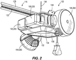
- FIGS. 1-2 illustrate a garage door system 50 including a garage door opener 100 operatively coupled to a garage door 104.
- the garage door opener 100 includes a housing 108 supporting a motor that is operatively coupled to a drive mechanism 116.
- the drive mechanism 116 includes a transmission coupling the motor to a drive chain 120 having a shuttle 124 configured to be displaced along a rail assembly 128 upon actuation of the motor.
- the shuttle 124 may be selectively coupled to a trolley 132 that is slidable along the rail assembly 128 and coupled to the garage door 104 via an arm member.
- the trolley 132 is releaseably coupled to the shuttle 124 such that the garage door system 50 is operable in a powered mode and a manual mode.
- the trolley 132 is coupled to the shuttle 124 and the motor is selectively driven in response to actuation by a user (e.g., via a key pad or wireless remote in communication with the garage door opener 100).
- the drive chain 120 is driven by the motor along the rail assembly 128 to displace the shuttle 124 (and, therefore, the trolley 132), thereby opening or closing the garage door 104.
- the trolley 132 is decoupled from the shuttle 124 such that a user may manually operate the garage door 104 to open or close without resistance from the motor.
- the trolley 132 may be decoupled, for example, when a user applies a force to a release cord 136 to disengage the trolley 132 from the shuttle 124.
- other drive systems are included such that, for example, the drive mechanism 116 includes a transmission coupling the motor to a drive belt that is operatively coupled to the garage door 104 via a rail and carriage assembly.
- the housing 108 is coupled to the rail assembly 128 and a surface above the garage door (e.g., a garage ceiling or support beam) by, for example, a support bracket 148.
- the garage door opener further includes a light unit 152 including a light (e.g., one or more light emitting diodes (LEDs)) enclosed by a transparent cover or lens 156), which provides light to the garage.
- the light unit 152 may either be selectively actuated by a user or automatically powered upon actuation of the garage door opener 100. In one example, the light unit 152 may be configured to remain powered for a predetermined amount of time after actuation of the garage door opener 100.
- the garage door opener 100 further includes an antenna 158 enabling the garage door opener 100 to communicate wirelessly with other devices, such as a smart phone or network device (e.g., a router, hub, or modem), as described in further detail below.
- the garage door opener 100 is also configured to receive, control, and/or monitor a variety of accessory devices or modules, such as a backup battery unit 189, a speaker 192, a fan 194, an extension cord reel 196, among others.
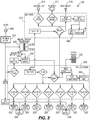
- FIG. 3 illustrates a block power diagram of the garage door opener 100.
- the garage door opener 100 includes a terminal block 202 configured to receive power from an external power source 204, such as a standard 120 VAC power outlet.
- the terminal block 202 directs power, via a transformer 208, to a garage door opener (GDO) board 210 for supply to components thereof as well as a motor 211 (used to drive the drive mechanism 116, as described above), LEDs 214 (of the light unit 152), and garage door sensors 216.
- the terminal block 202 further directs power via the transformer 208 to a wireless board 220 and components thereof, as well as a wired keypad 222 and module ports 223.
- the terminal block 202 also directs power to a battery charger 224 and AC ports 228.
- the module ports 223 are configured to receive various accessory devices, such as a speaker, a fan, an extension cord reel, a parking assist laser, an environmental sensor, a flashlight, and a security camera.
- accessory devices such as a speaker, a fan, an extension cord reel, a parking assist laser, an environmental sensor, a flashlight, and a security camera.
- One or more of the accessory devices are selectively attachable to and removable from the garage door opener 100, and may be monitored and controlled by the garage door opener 100.
- the wireless board 220 includes a wireless microcontroller 240, among other components.
- the GDO board 210 includes, among other components, a garage door opener (GDO) microcontroller 244 and a radio frequency (RF) transceiver 246.
- GDO garage door opener
- RF radio frequency
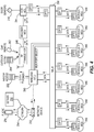
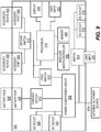
- FIG. 4 illustrates a block communication diagram of the garage door opener 100.
- the wireless microcontroller 240 is coupled to the antenna 158 and enables wireless communication with a server 250 via a network device 252 and network 254, as well as with a smart phone 256 (and other similar external devices, such as tablets and laptops).
- the network device 252 may be, for example, one or more of a router, hub, or modem.
- the network 254 may be, for example, the Internet, a local area network (LAN), another wide area network (WAN) or a combination thereof.
- the wireless microcontroller 240 may include, for example, a Wi-Fi radio including hardware, software, or a combination thereof enabling wireless communications according to the Wi-Fi protocol.
- the wireless microcontroller 240 is configured to communicate with the server 250 via the network device 252 and network 254 using other wireless communication protocols.
- the network 254 may include various wired and wireless connections to communicatively couple the garage door opener 100 to the server 250.
- the wireless microcontroller 240 also includes wired communication capabilities for communicating with the GDO microcontroller 244 via the multiplexor 260.
- the wireless microcontroller 240 and the GDO microcontroller 244 are directly coupled for communication.
- the wireless microcontroller 240 and the GDO microcontroller 244 are combined into a single controller.
- the RF transceiver 246 is wirelessly coupled to various user actuation devices, including one or more wireless remotes 262 and wireless keypads 264, to receive and provide to the GDO microcontroller 244 user actuation commands (e.g., to open and close the garage door 104).
- the smart phone 256 may also receive user input and, in response, provide (directly or via the network 254) to the wireless microcontroller 240 user actuation commands for the garage door opener 100 or commands to control one or more of the accessory devices.
- the multiplexor 260 enables communication between and among the wireless microcontroller 240, the GDO microcontroller 244, and the accessory microcontrollers 266 (of the accessory devices previously noted).
- the housing 108 includes accessory ports 162 that receive and support accessory devices, as noted above, which are modular, interchangeable accessory devices and are generically referred to as the accessory devices 200 (see, e.g., FIG. 2 )
- the housing 108 has eight accessory ports 162 with two ports 162 disposed on each side of the housing 108.
- this configuration is merely exemplary - that is, the housing 108 may include more than eight ports 162 or less than eight ports 162, and each side of the housing 108 may include more or less than two ports 162.
- the housing 108 may include more or less than four sides with each having one or more ports 162, and other surfaces of the housing (e.g., the top and bottom) may include one or more ports 162.
- each port 162 includes a communication interface 166 and a coupling interface 170.
- the communication interface 166 includes an electrical connector 174 disposed within a recess 178.
- the electrical connector 174 is configured to facilitate electrical communication and data communication between the accessory device 200 and the garage door opener 100.
- the electrical connector 174 may be any type of powered input/output port. Additionally, in further embodiments the electrical connector 174 may define separate power connectors and data connectors, which may similarly be any type of power connectors and data connectors.
- two slots 182 are formed on either side of the electrical connector 174 and receive a portion of an accessory device 200 to align and mechanically couple the accessory device 200 with housing 108.
- the coupling interface 170 is defined by a pair of spaced apart, raised surfaces 186 defined on either side of the communication interface 166.
- Each raised surface 186 includes a chamfered edge and has an aperture 190 defined there through.
- the raised surfaces 186 may be omitted in other embodiments.
- the apertures 190 are configured to receive portions of the accessory devices 200 to facilitate mechanical coupling of the accessory device 200 to the garage door opener 100.
- FIGS. 6 and 7 illustrate an example of one of the accessory devices 200 - an accessory speaker 212 - that is configured to be detachably coupled to the garage door opener 100.
- the speaker 212 is a wireless speaker 212 (e.g., a Bluetooth® speaker) that may be wirelessly coupled to a peripheral device, such as the smart phone 256 or a tablet.
- the speaker 212 receives an audio stream from the peripheral device communicating with the garage door opener 100, and subsequently drives a speaker 212 to output the audio stream using power from the garage door opener 100 via an electrical mounting interface 400.
- the wireless speaker 212 receives an audio stream wirelessly directly from the peripheral device via an integral transceiver, and drives a speaker 212 to output the audio stream using power from the garage door opener 100 via the electrical mounting interface 400.
- the speaker 212 includes a mechanical mounting interface 300 configured to be coupled to the coupling interface 170 of the housing 108, and the electrical mounting interface 400 configured to be coupled to the communication interface 166 of the housing 108.
- the mechanical mounting interface 300 includes a pair of hooks 304 that are received within the apertures 190 of the coupling interface 170, a pair of projections 308 disposed on opposing sides of the electrical mounting interface 400, and at least one protruding latch member 312 configured to engage a corresponding retention member on the housing 108.
- the projections 308 are configured to be received within the slots 182 to assist with alignment of the electrical mounting interface 400 and the communication interface 166.
- the speaker 212 When coupled, the speaker 212 receives power from the garage door opener 100 via a connection defined by the electrical mounting interface 400 and the communication interface 166. The speaker 212 also sends data to and receives data from the garage door opener 100 via a connection defined by the electrical mounting interface 400 and the communication interface 166.
- the speaker 212 further includes a controller (e.g., microcontroller 266) in communication with the wireless microcontroller 240 of the garage door opener 100.
- the controller includes a memory storing an initial data set including a unique identifier, a predetermined initial status field, and a predetermined initial settings field that is communicated to the garage door opener 100 each time the speaker 212 is coupled to the port 162. Thereafter, the controller is configured to send and receive data from, for example, the server 250 via the wireless microcontroller 240. More specifically, the controller receives updates to the settings field of the data set based on data received from the wireless microcontroller 240. The controller also updates the status field of the data set, which is sent to the wireless microcontroller 240 for communication to the peripheral device via the server 250.
- the status field includes, for example, on/off state of the speaker, the pairing status (e.g., Bluetooth® pairing status), and speaker volume, among others.
- the settings field includes an on/off toggle, a pairing toggle (e.g., to turn pairing on/off), and a volume value, among others.
- the user may set the values for the settings field (e.g., via the smart phone 256 or other peripheral device), which updates the speaker 212 to turn on/off, turn pairing on/off, or alter the volume of the speaker.
- the smart phone 256 may communicate updated settings for the settings field on the server 250.
- the server 250 sends the updated settings to the speaker 212 via the network 254, network device 252, and wireless microcontroller 240.
- Each of the accessory devices 200 may be interchangeably coupled to the ports 162 of the housing 108 due to the common mechanical mounting interfaces 300 and electrical mounting interfaces 400. In other words, each accessory device 200 may be coupled to any port 162 on the housing.
- This modular design allows a user to couple desired accessory devices 200 to the garage door opener 100 in a preferred location, while removing accessory devices 200 that the user does not require. This modular design allows the user to customize the garage door opener 100 to fit their specific needs.
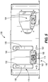
- FIGS. 8A-B and 9 illustrate a charger 500 that includes a housing 508 defining at least one battery receiving port 530, at least one accessory device receiving port or accessory port 562, at least one AC power outlet 516, at least one DC power outlet 520, a user input 524, a light or indicator 528, and a power cord 532 configured to be connected to an external power source.
- the housing 508 is configured as a rectangular housing 508 including a lower support face configured to support the housing on a surface (not shown), four sidewalls 536, and a port face 538 opposite the support face that includes a port groove 542 defined therein.
- the port groove 542 includes the battery receiving port 530 disposed in a central location on the port face 538 with two accessory device receiving ports 562 disposed on either side of the battery receiving port 530 (e.g., to the left and to the right in FIG. 8A ).
- Two DC power outlets 520 are defined in the port groove 542 adjacent the battery receiving port 530 between the accessory device receiving ports 562.
- Two AC power outlets 516 are defined in the port groove 542 adjacent the battery receiving port 530 between the accessory device receiving ports 562, such that the AC power outlets 516 are each defined between one accessory device receiving port 562 and a DC power outlet 520.
- a light 528 and a user input 524 are also defined in the port groove 542.
- the spatial configuration of the charger 500 is exemplary and may be varied in other embodiments.
- the charger 500 may include two or more battery receiving ports 530, more or less than two accessory device receiving ports 562, more or less than two AC power outlets 516, more or less than two DC power outlets 520, more than one user input 524, and more than one light 528.
- the AC power outlets 516 are illustrated as standard 3-prong AC outlets 516. However, in other embodiments, the AC power outlets 516 may be any suitable AC power outlets.
- the DC power outlets 520 are illustrated as USB ports. However, in other embodiments, the DC power outlets 520 may be any suitable DC power outlets 520.
- the charger 500 in contrast to the garage door opener 100, is a non-motorized device. In other words, the charger 500 does not include a motor within or supported by the housing 508 that supports the charging circuitry. Stated another way, the charger 500 and the housing 508 are independent of a motor because the charger does not include a motor within or supported by the housing 508 that supports the charging circuitry. Additionally, the charger 500 is portable between uses and not fixedly mounted to garage or other structure to open or close a garage door. For example, the charger 500 may include a carrying handle or handles in some embodiments, and one or more supporting feet on the lower support face extending downward from the housing 508 to support the housing 508 when the charger is resting on a support surface.
- FIG. 8B illustrates an example of the accessory receiving port 562.
- the accessory receiving ports 562 are similar to the ports 162 disposed on the housing 108 such that the accessory receiving ports 562 can receive the same accessory devices 200 described above.
- the accessory port 562 includes a communication interface 566 and a coupling interface 570.
- the communication interface 566 includes an electrical connector 574 disposed within a recess 578 on a planar support surface.
- the electrical connector 574 is configured to facilitate electrical communication and data communication between the accessory device 200 and the charger 500 (e.g., to couple the accessory device 200 to a power source).
- the electrical connector 574 may be any type of powered input/output port.
- the electrical connector 574 may define separate power connectors and data connectors, which may similarly be any type of power connectors and data connectors.
- Two slots 582 are formed on either side of the electrical connector 574 and receive a portion of an accessory device 200 to align and mechanically couple the accessory device 200 with housing 508.
- the coupling interface 570 is defined by a pair of spaced apart apertures 590 disposed on an upper end of the support surface and a catch 594 defined in a groove.
- Each of the apertures 590 is configured to receive portions of the accessory devices 200 to facilitate mechanical coupling of the accessory device 200 to the charger 500.
- the catch 594 is configured to receive, for example, the latch 312 of the accessory device 200 to secure and maintain engagement of the accessory device 200 to the charger 500.
- the groove defines lower surfaces for supporting the accessory device 200.
- the battery receiving port 530 includes a recess 546 that is sized and shaped to receive a battery pack 505.
- the battery receiving portion 530 includes charger electrical contacts that are configured to mechanically and electrically engage battery contacts to communicate electrical power and/or data signals therebetween.
- the battery receiving portion 530 includes two slots 548 disposed on opposed sides of the recess 546 that are configured to receive battery pack latch members 1370 (see FIG. 11 ) to secure and maintain engagement of the battery pack 505 to the charger 500.
- the battery receiving portion 530 is configured to receive a battery pack 505 that is inserted along a vertical insertion axis.
- the battery receiving portion 530 may be configured to receive the battery pack 505 configured as a 'slide on' battery pack that is inserted along a horizontal insertion axis.
- the power cord 532 is coupled to the housing 508 via a power cord housing 534.
- the power cord housing 534 is pivotally coupled to the charger housing 508 such that the power cord housing 534 is pivotal about a pivot axis.
- the power cord housing 534 may be configured to support a length of excess power cord 532.
- the power cord housing 534 may include, for example, a cord reel that automatically retracts and winds a length of excess power cord 532.
- the power cord 532 may be directly coupled to the housing 508.
- the power cord 532 itself includes a standard 3 prong male adapter 560 configured to be coupled to an external power source (e.g., a standard 120 VAC power outlet).
- an external power source e.g., a standard 120 VAC power outlet.
- the power cord 532 may include other suitable adapters for coupling the charger to an external power source.
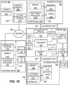
- FIG. 9 illustrates a block diagram of the charger 500.
- the charger 500 includes the two AC power outlets 516 coupled to the external power source via a switch 604, a power conditioning circuit 608, two DC power outlets 520, a charger circuit 612 coupled to the battery receiving port 530, a processor 514, and two accessory device receiving ports 562 each interconnected by one or more bus connections.
- the switch 604 is configured to direct AC power from the external power source to the AC outlets 516 when the switch is closed.
- the switch 604 may be operated, for example, by user input 524 (e.g., toggle switch) disposed on the housing 508.
- the switch 604 may be two separate switches, each configured to direct power to an AC outlet 516 when the corresponding switch is closed.
- the power conditioning circuit 608 is configured to receive and covert AC input from the external power source to a DC power output.
- the power conditioning circuit 608 may include, for example, one or more rectifiers, transformers, filters, etc to accomplish the conversion. After conversion, the DC power is directed to the DC outlets 520, the charger circuit 612, the processor 514, and the accessory device ports 562.
- the charging circuit 612 is configured to control the flow of current to the battery pack 505 in order to charge the pack 505.
- the charging circuit 612 may include a processor that is configured to monitor battery pack properties (e.g., type of battery, charge state, temperature, number of charge cycles, etc.) to determine and execute a charging protocol stored in a memory of the charging circuit 612.
- the charging protocol may include a constant or variable current application, constant or variable voltage application, a programmed sequence of constant/variable current and constant/variable voltage, and automatic shut-off in response to monitored battery pack properties (e.g., at completed charge, a temperature threshold, etc.).
- charger 500 includes the processor 514 that is coupled to the power conditioning circuit 608, a memory 509, a wireless microcontroller 540, a user input 510, a display 506, and each of the accessory devices 200 via the accessory device receiving ports 562.
- the processor 514 executes software, which may be stored in the memory 509, to carry out the functionality of the charger 500 described herein.
- the user input 510 has at least one actuator (e.g., button, switch, lever, touchscreen, etc.) that is configured to control operation of the charger 500.
- the user input 510 includes two actuators on an outside of the housing 508 (e.g., similar to the switch 524 and located on the port groove 542) that are each configured to operate a first switch 512 and a second switch 513, respectively.
- the first switch 512 is disposed between the power conditioning circuit 608 and the processor 514 of the charger 500 as well as the accessory device 200 such that the first switch 512 controls the on/off state of the processor (i.e., whether power is supplied from the power conditioning circuit 608 to the processor 514).
- the power conditioning circuit 608 supplies DC power to the processor 514 to turn the charger 500 to an on or active state.
- the second switch 513 is disposed between the power conditioning circuit 608 and the accessory device 200 such that the second switch 513 controls the on/off state of the accessory device 200 coupled to accessory ports 562 (i.e., whether power supplied to the processor 514 from the power conditioning circuit 608 is passed to the accessory device 200).
- the power conditioning circuit 608 supplies DC power (received via the first switch 512 when the first switch 512 is closed) to at least one of the accessory devices 200.
- the charger 500 provides power to the accessory device 200 when both the first switch 512 and the second switch 513 are closed.
- the first switch 512 and the second switch 513 are configured to be selectively actuated by the user (e.g., by a button, switch, lever, touchscreen, etc.).
- the actuators for the first switch 512 and the second switch 513 may physically open or close the first switch 512 and the second switch 513 upon actuation, or the actuator may communicate a control signal to the processor 514 of the charger 500 upon actuation, which causes the processor 514 to control the first switch or second switch to open or close.
- the wireless microcontroller 540 enables wireless communication similar to the wireless microcontroller 240 described above with respect to the garage door opener 100.
- the charger 500 is configured to wirelessly communicate via a network 554 with a server 550 and a peripheral device 556 (e.g., a smart phone, tablet, laptop, or the like).
- the network 554 may be, for example, the Internet, a local area network (LAN), another wide area network (WAN) or a combination thereof, and may include one or more network devices similar to the network device 252.
- the network 554 may also include various wired and wireless connections to communicatively couple the charger 500 to the server 550 and peripheral device 556.
- the wireless microcontroller 540 may include, for example, a Wi-Fi radio including hardware, software, or a combination thereof enabling wireless communications according to the Wi-Fi protocol.
- the wireless microcontroller 540 is configured to communicate with the server 550 via the network 554 using other wireless communication protocols. Regardless of the protocol, the wireless microcontroller 540 includes a wireless transceiver to enable wireless communications.
- the wireless microcontroller 540 and processor 514 may be collectively referred to as an electronic controller or processor of the charger 500.
- the electronic controller may execute software, which may be stored in the memory 509 or a memory of the wireless microcontroller 540, to carry out the functionality of the charger 500 described herein.
- the server 550 may be the same server (in whole or part) as the server 250, the network 554 may be the same network (in whole or part) as the network 254, and the peripheral device 556 may be the same peripheral device (in whole or part) as the smart phone 256.
- Such communications may include the communication of a data set including at least identifier (ID) data, settings data, and status data, from each of the different accessory devices 200 coupled to the charger 500 to the peripheral device 556 via the wireless microcontroller 540.
- ID identifier
- the charger 500 acts as an intermediary communication device or pass through device - that is, the wireless microcontroller 540 determines the accessory 200 is received in the port and understands data sets that it sends and receives is divided into categories (e.g., unique identifier, status, settings), but does not actually process or 'understand' the data contained within the data set. Rather, it simply routes the data set associated with each connected port to the peripheral device 556 via the server 550. This, for example, allows the charger 500 to receive one of multiple different accessories in a single port, and allows each accessory device 200 to be moved from a first port to another port (when the charger 500 includes multiple accessory device ports).
- the wireless microcontroller 540 determines the accessory 200 is received in the port and understands data sets that it sends and receives is divided into categories (e.g., unique identifier, status, settings), but does not actually process or 'understand' the data contained within the data set. Rather, it simply routes the data set associated with each connected port to the peripheral device 556 via the server
- the server 550 may maintain data sets for each accessory device.
- the charger 500 receives data from the accessory device 200 and communicates the data to the server 550 to update the data set.
- the server 550 communicates (e.g., based on a push or pull operation) the updated data set to the peripheral device 556 via the network 554.
- the peripheral device 556 may generate (e.g., based on user input) data that is transmitted, via the network 554, to the server 550 to update the data set associated with the accessory device 200.
- the server 550 in turn, communicates (e.g., based on a push or pull operation) the updated data set to the accessory device 200 via the network 554 and the wireless microcontroller 540.
- the charger 500 directly communicates information between the accessory device 200 and the peripheral device 556 via the network 554, rather than via the server 550.
- the communications between the peripheral device 556 and the accessory device 200 enable the peripheral device 556 to determine the identity of the accessory device 200 (based on obtained ID data), to determine the status and settings of the accessory device 200 (based on received status data and settings data), and to control the accessory device 200 (e.g., to turn on/off the device and to vary settings and thresholds of the device based on sending settings data).
- the charger is not configured to communicate with the peripheral device 556.
- the wireless microcontroller 540 may not be included in some embodiments.
- either the accessory device 200 or the charger 500 includes user input devices to control the operating state of the accessory device 200.
- the charger 500 may further obtain status information from the accessory device 200 coupled thereto and provide the status information to a user via the display 506.
- FIG. 10 also illustrates one exemplary block diagram of the accessory devices 200 in detail.
- FIG. 10 illustrates two accessory devices 200, each being similarly configured. Accordingly, the description of one of the accessory devices 200 similarly applies to both accessory devices 200.
- the accessory devices 200 may be a speaker (e.g., the speaker 212), a fan, an extension cord reel, an environmental sensor, a flashlight, or a security camera, among others.
- the accessory device 200 includes a controller 1200 having a memory 1205 and an electronic processor 1210, one or more sensors 1215 (e.g., temperature sensors, humidity sensors, and carbon monoxide sensors, etc.) and one or more loads 1220 (e.g., indicators, speakers, cameras, lights, motors, etc.) coupled by a bus 1225.
- sensors 1215 e.g., temperature sensors, humidity sensors, and carbon monoxide sensors, etc.
- loads 1220 e.g., indicators, speakers, cameras, lights, motors, etc.
- the controller 1200 is coupled to the charger 500 via the electrical mounting interface 400 to enable data communications between the controller 1200 and the charger 500 and to provide power to the accessory 200.
- the controller 1200 executes software, which may be stored in memory 1205, to carry out the function of the accessory device 200 described herein (e.g., to receive, store data from the sensor(s) 1215, to control the load(s) 1220, to communicate data to and receive data from the charger 500).
- the particular sensors 1215, loads 1220, and functionality of the controller 1200 varies depending on the type of accessory 200.
- the accessory device 200 may receive settings data from the peripheral device 556 via the charger 500, as described above.
- the controller 1200 may store the settings data (e.g., in the memory 1205) and control the load(s) 1120, sensor(s) 1215, or both, in accordance with the settings data.
- the electronic processor 1210 may control a fan motor (an example of the load 1220) to turn on, off, or adjust speed based on the received settings data.
- the accessory device 200 is configured to interface with the charger 500 in the same way that the accessory device 200 interfaces with the garage door opener 100.
- the mechanical mounting interface 300 of the accessory device 200 (see FIGS. 6-7 ) is configured to be coupled to the coupling interface 570 of the housing 508, and the electrical mounting interface 400 of the accessory device 200 (see FIGS. 6-7 ) is configured to be coupled to the communication interface 566 of the housing 508.
- the hooks 304 of the mechanical mounting interface 300 are received within the apertures 590 of the coupling interface 570, and the pair of projections 308 are received within the slots 582, the latch member 312 engages the catch 594, and the electrical mounting interface 400 electromechanically engages the communication interface 566.
- the accessory device 200 When coupled, the accessory device 200 receives power from the charger 500 via a connection defined by the electrical mounting interface 400 and the communication interface 166. The accessory device 200 also sends data to and receives data from the charger 500 via a connection defined by the electrical mounting interface 400 and the communication interface 566.
- FIG. 10 also illustrates one exemplary block diagram of the peripheral device 556 in further detail.
- the peripheral device 556 includes a communications interface 1150, a memory 1155, an electronic processor 1160, a display 1165, and user input/output 1170 coupled by bus 1175.
- the communication interface 1150 is coupled (wired and/or wirelessly) to the network 554 and enables the electronic processor 1160 (and, thereby, the peripheral device 556) to communicate with the server 550 (and, thereby, the charger 500 and the accessory device 200).
- the electronic processor 1160 executes software, which may be stored in the memory 1155, to carry out the functionality of the peripheral device 556 described herein (e.g., send data to and from the charger 500 and to control and monitor operation of the accessory device 200).
- the user input/output 1170 include one or more push buttons, toggle switches, speakers, and vibration generators for receiving user input and providing user output.
- the display 1165 is a touch screen display and is part of the input/output 1170. The display provides visual output regarding the charger 500 and the accessory device 200.
- FIG. 10 also illustrates an exemplary block diagram of the server 550.
- the server 550 includes a network communication interface 1315, a server memory 1305, and a server processor 1310 coupled by bus 1320.
- the network communication interface 1315 is coupled (wired and/or wirelessly) to the network 554 and enables the server processor 1310 (and, thereby, the server 550) to communicate with the charger 500 (and, thereby, the accessory device 200) and the peripheral device 556.
- the server memory 1305 stores the accessory information (e.g., the data set including the ID data, settings data, and status data for each of the accessory devices 200), as well as operational data and software.
- the server processor 1310 executes software, which may be stored in the memory 1305, to carry out the functionality of the server 550 described herein. For example, the server processor 1310 reads and writes the accessory information to the memory 1305. Although illustrated as a single server, the server 550 may be implemented by one or more servers co-located or located separately from one another and, for instance, coupled by various communication networks.
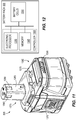
- the battery pack 505 is coupled to the charger 500 via the battery receiving port 530.
- the battery receiving port 530 includes the electrical and mechanical connections of the battery pack 505 and the charger 500, including the battery terminals (see contacts 1390 of FIG. 11 ) and charger terminals for transmitting power and, in some instances, data; the battery receiving port 530 of the charger 500 described with respect to FIG. 8A is used to secure the battery pack 505 to the charger 500; and the portion of the battery pack 505 received in the battery receiving portion 530 (see insertion portion 1375 of FIG. 11 ).
- the battery pack 505 includes battery cells 1350 and a battery controller 1355 having an electronic processor 1360 and a memory 1365.
- the electronic processor 1360 executes instructions stored in the memory 1365 to control the functionality of the battery pack 505 described herein, such as to control the charge and discharge of the battery cells 1350 (e.g., via switching elements (not shown)).
- the battery cells 1350 may provide a voltage output of about 18 volts, of another value in a range between 17 to 21 volts, or another value, such as about 12 volts, about 28 volts, about 36 volts, about 48 volts, another value or range between 12 to 48 volts, or another value.
- the term "about” may indicate a range of plus or minus 20%, 15%, 10%, 5%, or 1% from an associated value.
- the battery cells 1350 may have various chemistry types, such as lithium ion, a nickel cadmium, etc.
- FIG. 11 illustrates an example of the battery pack 505 that may be coupled to the charger 500 via the battery receiving port 530.
- the battery pack 505 includes latches 1370 on either side of the pack for engaging the slots 548 of the battery receiving port 530 on the charger 500.
- the battery pack 505 further includes an insertion portion 1375 that is received by the battery receiving portion 530 of the charger 500.
- the insertion portion 1375 includes a top support portion 1380 having a stem 1385 extending vertically from the top support portion 1380.
- the stem 1385 has contacts 1390 that supply power to the charger 500 and may communicate data between the charger 500 and the battery pack 505.
- the battery pack 505 further includes a fuel gauge 1395 that indicates a state of charge of the battery pack.
- the battery pack 505 may be a power tool battery pack configured to power a power tools (e.g., drills/drivers, impact drills/drivers, hammer drills/drivers, saws, and routers) having a battery receiving portion similar to the battery receiving portion 530.
- a power tools e.g., drills/drivers, impact drills/drivers, hammer drills/drivers, saws, and routers
- the charger 500 is illustrated as having one port 562, in some embodiments, the charger 500 includes more than one port 562 for coupling to a plurality of the battery packs 505. In such embodiments, the charger 500 is operable to serve as a communication interface to the network 554 such that each of the accessory devices 200, when coupled to the charger 500, may communicate with the server 550 and peripheral device 556 for monitoring and control as described above.
- embodiments described herein provide, among other things, a method of operating an accessory device system including a garage door opener, a charger, and one or more accessory devices whereby a first accessory device of the one or more accessory devices may be coupled to the garage door opener, operated based on power from the garage door opener, removed from the garage door opener, coupled to the charger, and then operated based on power from the charger.
- an accessory device system in another embodiment, includes a garage door opener, a charger, and one or more accessory devices whereby the garage door opener has a first accessory device port configured to couple to the one or more accessory devices and the charger has a second accessory device port configured to couple to the one or more accessory devices.
- the garage door opener is further configured to provide power to a first accessory device of the one or more accessory devices via the first accessory device port.
- the charger further includes a battery receiving portion configured to be selectively coupled to a battery pack and to charge the battery pack, and the charger is further configured to provide power to the first accessory device via the second accessory device port.
- an accessory device system in another embodiment, includes a charger, a battery pack selectively coupled to a battery receiving portion of the charger to receive charging current, and a first accessory device coupled to an accessory device port of the charger.
- the charger further includes an electronic controller having a wireless transceiver and operable to communicate with a peripheral device to one or more of provide identity and status information regarding the first accessory device and to receive settings data to control the first accessory device.
- the charger receives the identity and status information from the first accessory device, and provides the settings data to the first accessory device to control the first accessory device.
- the peripheral device and the charger communicate via a network and server, and the charger communicates wirelessly with the network via the wireless transceiver.
- a method of operating an accessory device system where the system includes a charger, a battery pack selectively coupled to a battery receiving portion of the charger to receive charging current, and a first accessory device coupled to an accessory device port of the charger.
- the method further includes the charger receiving identity and status information from the first accessory device, and communicating, by an electronic controller of the charger having a wireless transceiver, with peripheral device to provide the identity and status information regarding the first accessory device to the peripheral device.
- the method further includes communicating, via the wireless transceiver of the charger, with the peripheral device to receive settings data to control the first accessory device, and providing the settings data to the first accessory device to control the first accessory device.
- the peripheral device and the charger communicate via a network and server, and the charger communicates wirelessly with the network via the wireless transceiver.
Abstract
Description
- The present invention relates to a battery charging device, and more particularly to a battery charging device including electromechanical ports for accessory devices.
- The present invention provides, in one aspect, an accessory device system including an accessory device, a garage door opener including a first accessory device port configured to couple to the accessory device and provide power to the accessory device via the first accessory device port, and a charger. The charger includes a second accessory device port configured to couple to the accessory device, and a battery receiving portion configured to be selectively coupled to a battery pack and to charge the battery pack. The charger is configured to provide power to the first accessory device via the second accessory device port.
- The present invention provides, in one aspect, a method of operating an accessory device system including a garage door opener, a charger, and an accessory device. The method includes receiving, by a first accessory device port on the garage door opener, the accessory device. The garage door opener provides power to the accessory device via the first accessory device port. The first accessory device port then disconnects from the accessory device and the accessory device is received by a second accessory device port on the charger. The charger then provides power to the accessory device via the second accessory device port.
- The present invention provides, in one aspect, a method of operating an accessory device system including an accessory device. The method includes receiving the accessory device by an accessory device port on a charger that is portable and non-motorized. The charger provides power to the accessory device via the accessory device port and receives via the identity and status data from the accessory device. An electronic controller of the charger having a wireless transceiver sends the identity and status data regarding the accessory device to a peripheral device and receives settings data regarding the accessory device from the peripheral device. The charger provides the settings data to the accessory device to control the accessory device.
- Another embodiment provides an accessory device system comprising: an accessory device; a garage door opener including a first accessory device port configured to couple to the accessory device and provide power to the accessory device via the first accessory device port; and a charger including a second accessory device port configured to couple to the accessory device, and a battery receiving portion configured to be selectively coupled to a battery pack and to provide charging power to the battery pack, wherein the charger is configured to provide power to the accessory device via the second accessory device port.
- The battery pack may be a power tool battery pack having a battery cell with at least one selected from the group consisting of nickel cadmium chemistry and lithium ion chemistry.
- The charger may further include an electronic controller having a wireless transceiver and configured to: communicate with a peripheral device to one or more of provide identity and status information regarding the accessory device and to receive settings information to control the accessory device, receive the identity and status information from the accessory device, and provide the settings information to the accessory device to control the accessory device.
- The charger may further include an AC outlet port and a DC outlet port, or the charger may further include a third accessory device port configured to couple to a second accessory device, and the charger may be configured to provide power to the second accessory device via the third accessory device port.
- The charger may further include an electronic controller having a wireless transceiver and configured to: communicate with a peripheral device to one or more of provide identity and status information regarding the accessory device and the second accessory device and to receive settings information to control the accessory device and the second accessory device, receive the identity and status information from the accessory device and the second accessory device, and provide the settings information to the accessory device and second accessory device to control the accessory device and the second accessory device.
- The accessory device may be at least one selected from the group consisting of a wireless speaker, a fan, or a light, or the accessory device may be a first accessory device and the system further comprises a second accessory device configured to couple to the first accessory device port and to the second accessory device port.
- Another embodiment provides a method of operating an accessory device system including a garage door opener, a charger, and an accessory device, the method comprising: receiving, by a first accessory device port on the garage door opener, the accessory device; providing, by the garage door opener, power to the accessory device via the first accessory device port; disconnecting, by the first accessory device port, from the accessory device; receiving, by a second accessory device port on the charger, the accessory device; and providing, by the charger, power to the accessory device via the second accessory device port.
- The method may further comprise: receiving, by a battery receiving portion of the charger, a battery pack; and charging, by the charger, the battery pack.
- The battery pack may be a power tool battery pack having a battery cell with at least one selected from the group consisting of nickel cadmium chemistry and lithium ion chemistry.
- The method may further comprise: receiving, by a third accessory device port on the charger, a second accessory device after disconnecting the accessory device; and providing, by the charger, power to the second accessory device via the third accessory device port.
- The accessory device may be at least one selected from the group consisting of a wireless speaker, a fan, or a light.
- A further embodiment provides a method of operating an accessory device system including an accessory device, the method comprising: receiving the accessory device by an accessory device port on a charger that is portable and non-motorized; providing, by the charger, power to the accessory device via the accessory device port; receiving, via the charger, identity and status data from the accessory device; sending, by an electronic controller of the charger having a wireless transceiver, the identity and status data regarding the accessory device to a peripheral device; receiving, by the electronic controller, settings data regarding the accessory device from the peripheral device; and providing, via the charger, the settings data to the accessory device to control the accessory device.
- The method may further comprise: receiving, by a battery receiving portion of the charger, a battery pack; and charging, by the charger, the battery pack.
- The battery pack may be a power tool battery pack having nickel cadmium cell chemistry or lithium ion chemistry, or the accessory device may be a wireless speaker, a fan, or a light, and the identity data may indicate that the accessory device is a wireless speaker, a fan, or a light, or the peripheral device and the charger may communicate via a network and server, or the charger may communicate wirelessly with the network via the wireless transceiver.
- The method may further comprise: disconnecting, by the accessory device port, from the accessory device; receiving, by the accessory device port, a second accessory device; providing, by the charger, power to the second accessory device via the accessory device port; receiving, by the charger via the accessory device port, second identity and status data from the second accessory device; sending, by the electronic controller, the second identity and status data regarding the second accessory device to the peripheral device; receiving, by the electronic controller, second settings data regarding the second accessory device from the peripheral device; and providing, via the charger, the second settings data to the second accessory device to control the second accessory device.
- Other features and aspects of the invention will become apparent by consideration of the following detailed description and accompanying drawings.
-
-
FIG. 1 is a view of a garage door opener system. -
FIG. 2 is a view of a garage door opener of the garage door system inFIG. 1 . -
FIG. 3 is a block power diagram of the garage door opener ofFIG. 2 . -
FIG. 4 is a block communication diagram of the garage door opener ofFIG. 2 . -
FIG. 5 is a side view of a housing of the garage door opener system ofFIG. 1 . -
FIG. 6 is a front perspective view of an accessory device for use with the garage door opener system ofFIG. 1 . -
FIG. 7 is a rear perspective view of the accessory device ofFIG. 6 . -
FIG. 8A is a top view of a charger. -
FIG. 8B is a view of an accessory receiving port of the charger ofFIG. 8A . -
FIG. 9 is a block diagram of the charger ofFIG. 8A . -
FIG. 10 is another block diagram of the charger ofFIG. 8A . -
FIG. 11 is a view of a battery pack that may be coupled to the charger ofFIG. 8A in some embodiments. -
FIG. 12 is a block diagram of the battery pack ofFIG. 11 . - Before any embodiments of the invention are explained in detail, it is to be understood that the invention is not limited in its application to the details of construction and the arrangement of components set forth in the following description or illustrated in the following drawings. The invention is capable of other embodiments and of being practiced or of being carried out in various ways. Also, it is to be understood that the phraseology and terminology used herein is for the purpose of description and should not be regarded as limiting.
-
FIGS. 1-2 illustrate agarage door system 50 including agarage door opener 100 operatively coupled to agarage door 104. Thegarage door opener 100 includes ahousing 108 supporting a motor that is operatively coupled to adrive mechanism 116. Thedrive mechanism 116 includes a transmission coupling the motor to adrive chain 120 having ashuttle 124 configured to be displaced along arail assembly 128 upon actuation of the motor. Theshuttle 124 may be selectively coupled to atrolley 132 that is slidable along therail assembly 128 and coupled to thegarage door 104 via an arm member. - The
trolley 132 is releaseably coupled to theshuttle 124 such that thegarage door system 50 is operable in a powered mode and a manual mode. In the powered mode, thetrolley 132 is coupled to theshuttle 124 and the motor is selectively driven in response to actuation by a user (e.g., via a key pad or wireless remote in communication with the garage door opener 100). As the motor is driven, thedrive chain 120 is driven by the motor along therail assembly 128 to displace the shuttle 124 (and, therefore, the trolley 132), thereby opening or closing thegarage door 104. In the manual mode, thetrolley 132 is decoupled from theshuttle 124 such that a user may manually operate thegarage door 104 to open or close without resistance from the motor. Thetrolley 132 may be decoupled, for example, when a user applies a force to arelease cord 136 to disengage thetrolley 132 from theshuttle 124. In some embodiments, other drive systems are included such that, for example, thedrive mechanism 116 includes a transmission coupling the motor to a drive belt that is operatively coupled to thegarage door 104 via a rail and carriage assembly. - The
housing 108 is coupled to therail assembly 128 and a surface above the garage door (e.g., a garage ceiling or support beam) by, for example, asupport bracket 148. The garage door opener further includes alight unit 152 including a light (e.g., one or more light emitting diodes (LEDs)) enclosed by a transparent cover or lens 156), which provides light to the garage. Thelight unit 152 may either be selectively actuated by a user or automatically powered upon actuation of thegarage door opener 100. In one example, thelight unit 152 may be configured to remain powered for a predetermined amount of time after actuation of thegarage door opener 100. - The
garage door opener 100 further includes anantenna 158 enabling thegarage door opener 100 to communicate wirelessly with other devices, such as a smart phone or network device (e.g., a router, hub, or modem), as described in further detail below. Thegarage door opener 100 is also configured to receive, control, and/or monitor a variety of accessory devices or modules, such as a backup battery unit 189, a speaker 192, a fan 194, an extension cord reel 196, among others. -
FIG. 3 illustrates a block power diagram of thegarage door opener 100. Thegarage door opener 100 includes aterminal block 202 configured to receive power from anexternal power source 204, such as a standard 120 VAC power outlet. Theterminal block 202 directs power, via atransformer 208, to a garage door opener (GDO)board 210 for supply to components thereof as well as a motor 211 (used to drive thedrive mechanism 116, as described above), LEDs 214 (of the light unit 152), andgarage door sensors 216. Theterminal block 202 further directs power via thetransformer 208 to awireless board 220 and components thereof, as well as awired keypad 222 andmodule ports 223. Theterminal block 202 also directs power to abattery charger 224 andAC ports 228. Themodule ports 223 are configured to receive various accessory devices, such as a speaker, a fan, an extension cord reel, a parking assist laser, an environmental sensor, a flashlight, and a security camera. One or more of the accessory devices are selectively attachable to and removable from thegarage door opener 100, and may be monitored and controlled by thegarage door opener 100. - The
wireless board 220 includes awireless microcontroller 240, among other components. TheGDO board 210 includes, among other components, a garage door opener (GDO)microcontroller 244 and a radio frequency (RF)transceiver 246. -
FIG. 4 illustrates a block communication diagram of thegarage door opener 100. Thewireless microcontroller 240 is coupled to theantenna 158 and enables wireless communication with aserver 250 via anetwork device 252 andnetwork 254, as well as with a smart phone 256 (and other similar external devices, such as tablets and laptops). Thenetwork device 252 may be, for example, one or more of a router, hub, or modem. Thenetwork 254 may be, for example, the Internet, a local area network (LAN), another wide area network (WAN) or a combination thereof. Thewireless microcontroller 240 may include, for example, a Wi-Fi radio including hardware, software, or a combination thereof enabling wireless communications according to the Wi-Fi protocol. In other embodiments, thewireless microcontroller 240 is configured to communicate with theserver 250 via thenetwork device 252 andnetwork 254 using other wireless communication protocols. Thenetwork 254 may include various wired and wireless connections to communicatively couple thegarage door opener 100 to theserver 250. As illustrated, thewireless microcontroller 240 also includes wired communication capabilities for communicating with theGDO microcontroller 244 via themultiplexor 260. In some embodiments, thewireless microcontroller 240 and theGDO microcontroller 244 are directly coupled for communication. In some embodiments, thewireless microcontroller 240 and theGDO microcontroller 244 are combined into a single controller. - The
RF transceiver 246 is wirelessly coupled to various user actuation devices, including one or morewireless remotes 262 andwireless keypads 264, to receive and provide to theGDO microcontroller 244 user actuation commands (e.g., to open and close the garage door 104). Thesmart phone 256 may also receive user input and, in response, provide (directly or via the network 254) to thewireless microcontroller 240 user actuation commands for thegarage door opener 100 or commands to control one or more of the accessory devices. Themultiplexor 260 enables communication between and among thewireless microcontroller 240, theGDO microcontroller 244, and the accessory microcontrollers 266 (of the accessory devices previously noted). - With reference to
FIG. 5 , thehousing 108 includesaccessory ports 162 that receive and support accessory devices, as noted above, which are modular, interchangeable accessory devices and are generically referred to as the accessory devices 200 (see, e.g.,FIG. 2 ) In the illustrated embodiment, thehousing 108 has eightaccessory ports 162 with twoports 162 disposed on each side of thehousing 108. However, this configuration is merely exemplary - that is, thehousing 108 may include more than eightports 162 or less than eightports 162, and each side of thehousing 108 may include more or less than twoports 162. Additionally, thehousing 108 may include more or less than four sides with each having one ormore ports 162, and other surfaces of the housing (e.g., the top and bottom) may include one ormore ports 162. - With continued reference to
FIG. 5 , eachport 162 includes acommunication interface 166 and acoupling interface 170. Thecommunication interface 166 includes anelectrical connector 174 disposed within a recess 178. Theelectrical connector 174 is configured to facilitate electrical communication and data communication between theaccessory device 200 and thegarage door opener 100. Theelectrical connector 174 may be any type of powered input/output port. Additionally, in further embodiments theelectrical connector 174 may define separate power connectors and data connectors, which may similarly be any type of power connectors and data connectors. In the illustrated embodiment, twoslots 182 are formed on either side of theelectrical connector 174 and receive a portion of anaccessory device 200 to align and mechanically couple theaccessory device 200 withhousing 108. Thecoupling interface 170 is defined by a pair of spaced apart, raisedsurfaces 186 defined on either side of thecommunication interface 166. Each raisedsurface 186 includes a chamfered edge and has anaperture 190 defined there through. However, the raisedsurfaces 186 may be omitted in other embodiments. Theapertures 190 are configured to receive portions of theaccessory devices 200 to facilitate mechanical coupling of theaccessory device 200 to thegarage door opener 100. -
FIGS. 6 and 7 illustrate an example of one of the accessory devices 200 - an accessory speaker 212 - that is configured to be detachably coupled to thegarage door opener 100. In the illustrated embodiment, thespeaker 212 is a wireless speaker 212 (e.g., a Bluetooth® speaker) that may be wirelessly coupled to a peripheral device, such as thesmart phone 256 or a tablet. In one embodiment, thespeaker 212 receives an audio stream from the peripheral device communicating with thegarage door opener 100, and subsequently drives aspeaker 212 to output the audio stream using power from thegarage door opener 100 via anelectrical mounting interface 400. In another embodiment, thewireless speaker 212 receives an audio stream wirelessly directly from the peripheral device via an integral transceiver, and drives aspeaker 212 to output the audio stream using power from thegarage door opener 100 via theelectrical mounting interface 400. - With reference to
FIG. 7 , thespeaker 212 includes amechanical mounting interface 300 configured to be coupled to thecoupling interface 170 of thehousing 108, and theelectrical mounting interface 400 configured to be coupled to thecommunication interface 166 of thehousing 108. Themechanical mounting interface 300 includes a pair ofhooks 304 that are received within theapertures 190 of thecoupling interface 170, a pair ofprojections 308 disposed on opposing sides of theelectrical mounting interface 400, and at least one protrudinglatch member 312 configured to engage a corresponding retention member on thehousing 108. Theprojections 308 are configured to be received within theslots 182 to assist with alignment of theelectrical mounting interface 400 and thecommunication interface 166. When coupled, thespeaker 212 receives power from thegarage door opener 100 via a connection defined by theelectrical mounting interface 400 and thecommunication interface 166. Thespeaker 212 also sends data to and receives data from thegarage door opener 100 via a connection defined by theelectrical mounting interface 400 and thecommunication interface 166. - The
speaker 212 further includes a controller (e.g., microcontroller 266) in communication with thewireless microcontroller 240 of thegarage door opener 100. The controller includes a memory storing an initial data set including a unique identifier, a predetermined initial status field, and a predetermined initial settings field that is communicated to thegarage door opener 100 each time thespeaker 212 is coupled to theport 162. Thereafter, the controller is configured to send and receive data from, for example, theserver 250 via thewireless microcontroller 240. More specifically, the controller receives updates to the settings field of the data set based on data received from thewireless microcontroller 240. The controller also updates the status field of the data set, which is sent to thewireless microcontroller 240 for communication to the peripheral device via theserver 250. - In one embodiment, the status field includes, for example, on/off state of the speaker, the pairing status (e.g., Bluetooth® pairing status), and speaker volume, among others. The settings field includes an on/off toggle, a pairing toggle (e.g., to turn pairing on/off), and a volume value, among others. In this example, the user may set the values for the settings field (e.g., via the
smart phone 256 or other peripheral device), which updates thespeaker 212 to turn on/off, turn pairing on/off, or alter the volume of the speaker. For example, thesmart phone 256 may communicate updated settings for the settings field on theserver 250. In turn, for example, theserver 250 sends the updated settings to thespeaker 212 via thenetwork 254,network device 252, andwireless microcontroller 240. - Each of the
accessory devices 200 may be interchangeably coupled to theports 162 of thehousing 108 due to the common mechanical mounting interfaces 300 and electrical mounting interfaces 400. In other words, eachaccessory device 200 may be coupled to anyport 162 on the housing. This modular design allows a user to couple desiredaccessory devices 200 to thegarage door opener 100 in a preferred location, while removingaccessory devices 200 that the user does not require. This modular design allows the user to customize thegarage door opener 100 to fit their specific needs. -
FIGS. 8A-B and9 illustrate acharger 500 that includes ahousing 508 defining at least onebattery receiving port 530, at least one accessory device receiving port oraccessory port 562, at least oneAC power outlet 516, at least oneDC power outlet 520, auser input 524, a light orindicator 528, and apower cord 532 configured to be connected to an external power source. In the illustrated embodiment, thehousing 508 is configured as arectangular housing 508 including a lower support face configured to support the housing on a surface (not shown), foursidewalls 536, and aport face 538 opposite the support face that includes aport groove 542 defined therein. Theport groove 542 includes thebattery receiving port 530 disposed in a central location on theport face 538 with two accessorydevice receiving ports 562 disposed on either side of the battery receiving port 530 (e.g., to the left and to the right inFIG. 8A ). TwoDC power outlets 520 are defined in theport groove 542 adjacent thebattery receiving port 530 between the accessorydevice receiving ports 562. TwoAC power outlets 516 are defined in theport groove 542 adjacent thebattery receiving port 530 between the accessorydevice receiving ports 562, such that theAC power outlets 516 are each defined between one accessorydevice receiving port 562 and aDC power outlet 520. A light 528 and a user input 524 (e.g., a power switch) are also defined in theport groove 542. The spatial configuration of thecharger 500 is exemplary and may be varied in other embodiments. - Although one configuration of the
charger 500 was described with respect toFIG. 8A above, various modifications may be made to the illustratedcharger 500. For example, the number ofbattery receiving ports 530, accessorydevice receiving ports 562,AC power outlets 516,DC power outlets 520,user inputs 524, andlights 528 may be varied in other embodiments. That is, thecharger 500 may include two or morebattery receiving ports 530, more or less than two accessorydevice receiving ports 562, more or less than twoAC power outlets 516, more or less than twoDC power outlets 520, more than oneuser input 524, and more than onelight 528. TheAC power outlets 516 are illustrated as standard 3-prong AC outlets 516. However, in other embodiments, theAC power outlets 516 may be any suitable AC power outlets. TheDC power outlets 520 are illustrated as USB ports. However, in other embodiments, theDC power outlets 520 may be any suitableDC power outlets 520. - The
charger 500, in contrast to thegarage door opener 100, is a non-motorized device. In other words, thecharger 500 does not include a motor within or supported by thehousing 508 that supports the charging circuitry. Stated another way, thecharger 500 and thehousing 508 are independent of a motor because the charger does not include a motor within or supported by thehousing 508 that supports the charging circuitry. Additionally, thecharger 500 is portable between uses and not fixedly mounted to garage or other structure to open or close a garage door. For example, thecharger 500 may include a carrying handle or handles in some embodiments, and one or more supporting feet on the lower support face extending downward from thehousing 508 to support thehousing 508 when the charger is resting on a support surface. -
FIG. 8B illustrates an example of theaccessory receiving port 562. As shown inFIG. 8B , theaccessory receiving ports 562 are similar to theports 162 disposed on thehousing 108 such that theaccessory receiving ports 562 can receive the sameaccessory devices 200 described above. Accordingly, theaccessory port 562 includes acommunication interface 566 and acoupling interface 570. Thecommunication interface 566 includes anelectrical connector 574 disposed within arecess 578 on a planar support surface. Theelectrical connector 574 is configured to facilitate electrical communication and data communication between theaccessory device 200 and the charger 500 (e.g., to couple theaccessory device 200 to a power source). Theelectrical connector 574 may be any type of powered input/output port. Additionally, in further embodiments theelectrical connector 574 may define separate power connectors and data connectors, which may similarly be any type of power connectors and data connectors. Twoslots 582 are formed on either side of theelectrical connector 574 and receive a portion of anaccessory device 200 to align and mechanically couple theaccessory device 200 withhousing 508. - The
coupling interface 570 is defined by a pair of spaced apartapertures 590 disposed on an upper end of the support surface and acatch 594 defined in a groove. Each of theapertures 590 is configured to receive portions of theaccessory devices 200 to facilitate mechanical coupling of theaccessory device 200 to thecharger 500. Thecatch 594 is configured to receive, for example, thelatch 312 of theaccessory device 200 to secure and maintain engagement of theaccessory device 200 to thecharger 500. In addition, the groove defines lower surfaces for supporting theaccessory device 200. - With reference to
FIG. 8A , thebattery receiving port 530 includes arecess 546 that is sized and shaped to receive abattery pack 505. Thebattery receiving portion 530 includes charger electrical contacts that are configured to mechanically and electrically engage battery contacts to communicate electrical power and/or data signals therebetween. In addition, thebattery receiving portion 530 includes twoslots 548 disposed on opposed sides of therecess 546 that are configured to receive battery pack latch members 1370 (seeFIG. 11 ) to secure and maintain engagement of thebattery pack 505 to thecharger 500. In the illustrated embodiment, thebattery receiving portion 530 is configured to receive abattery pack 505 that is inserted along a vertical insertion axis. However, in other embodiments, thebattery receiving portion 530 may be configured to receive thebattery pack 505 configured as a 'slide on' battery pack that is inserted along a horizontal insertion axis. - With reference to
FIG. 8A , thepower cord 532 is coupled to thehousing 508 via apower cord housing 534. Thepower cord housing 534 is pivotally coupled to thecharger housing 508 such that thepower cord housing 534 is pivotal about a pivot axis. In some embodiments, thepower cord housing 534 may be configured to support a length ofexcess power cord 532. In another embodiment, thepower cord housing 534 may include, for example, a cord reel that automatically retracts and winds a length ofexcess power cord 532. In yet another embodiment, thepower cord 532 may be directly coupled to thehousing 508. - The
power cord 532 itself includes a standard 3prong male adapter 560 configured to be coupled to an external power source (e.g., a standard 120 VAC power outlet). However, in other embodiments, thepower cord 532 may include other suitable adapters for coupling the charger to an external power source. -
FIG. 9 illustrates a block diagram of thecharger 500. As illustrated, thecharger 500 includes the twoAC power outlets 516 coupled to the external power source via aswitch 604, apower conditioning circuit 608, twoDC power outlets 520, acharger circuit 612 coupled to thebattery receiving port 530, aprocessor 514, and two accessorydevice receiving ports 562 each interconnected by one or more bus connections. Theswitch 604 is configured to direct AC power from the external power source to theAC outlets 516 when the switch is closed. Theswitch 604 may be operated, for example, by user input 524 (e.g., toggle switch) disposed on thehousing 508. In an alternate embodiment, theswitch 604 may be two separate switches, each configured to direct power to anAC outlet 516 when the corresponding switch is closed. - The
power conditioning circuit 608 is configured to receive and covert AC input from the external power source to a DC power output. Thepower conditioning circuit 608 may include, for example, one or more rectifiers, transformers, filters, etc to accomplish the conversion. After conversion, the DC power is directed to theDC outlets 520, thecharger circuit 612, theprocessor 514, and theaccessory device ports 562. - The charging
circuit 612 is configured to control the flow of current to thebattery pack 505 in order to charge thepack 505. The chargingcircuit 612 may include a processor that is configured to monitor battery pack properties (e.g., type of battery, charge state, temperature, number of charge cycles, etc.) to determine and execute a charging protocol stored in a memory of the chargingcircuit 612. The charging protocol may include a constant or variable current application, constant or variable voltage application, a programmed sequence of constant/variable current and constant/variable voltage, and automatic shut-off in response to monitored battery pack properties (e.g., at completed charge, a temperature threshold, etc.). - With continued reference to
FIG. 9 ,charger 500 includes theprocessor 514 that is coupled to thepower conditioning circuit 608, amemory 509, awireless microcontroller 540, auser input 510, adisplay 506, and each of theaccessory devices 200 via the accessorydevice receiving ports 562. Theprocessor 514 executes software, which may be stored in thememory 509, to carry out the functionality of thecharger 500 described herein. Theuser input 510 has at least one actuator (e.g., button, switch, lever, touchscreen, etc.) that is configured to control operation of thecharger 500. In the illustrated embodiment, theuser input 510 includes two actuators on an outside of the housing 508 (e.g., similar to theswitch 524 and located on the port groove 542) that are each configured to operate afirst switch 512 and asecond switch 513, respectively. For example, thefirst switch 512 is disposed between thepower conditioning circuit 608 and theprocessor 514 of thecharger 500 as well as theaccessory device 200 such that thefirst switch 512 controls the on/off state of the processor (i.e., whether power is supplied from thepower conditioning circuit 608 to the processor 514). When thefirst switch 512 is closed, thepower conditioning circuit 608 supplies DC power to theprocessor 514 to turn thecharger 500 to an on or active state. Thesecond switch 513 is disposed between thepower conditioning circuit 608 and theaccessory device 200 such that thesecond switch 513 controls the on/off state of theaccessory device 200 coupled to accessory ports 562 (i.e., whether power supplied to theprocessor 514 from thepower conditioning circuit 608 is passed to the accessory device 200). When thesecond switch 513 is closed, thepower conditioning circuit 608 supplies DC power (received via thefirst switch 512 when thefirst switch 512 is closed) to at least one of theaccessory devices 200. In other words, thecharger 500 provides power to theaccessory device 200 when both thefirst switch 512 and thesecond switch 513 are closed. - The
first switch 512 and thesecond switch 513 are configured to be selectively actuated by the user (e.g., by a button, switch, lever, touchscreen, etc.). The actuators for thefirst switch 512 and thesecond switch 513 may physically open or close thefirst switch 512 and thesecond switch 513 upon actuation, or the actuator may communicate a control signal to theprocessor 514 of thecharger 500 upon actuation, which causes theprocessor 514 to control the first switch or second switch to open or close. - With reference to
FIG. 10 , thewireless microcontroller 540 enables wireless communication similar to thewireless microcontroller 240 described above with respect to thegarage door opener 100. For example, thecharger 500 is configured to wirelessly communicate via anetwork 554 with aserver 550 and a peripheral device 556 (e.g., a smart phone, tablet, laptop, or the like). Thenetwork 554 may be, for example, the Internet, a local area network (LAN), another wide area network (WAN) or a combination thereof, and may include one or more network devices similar to thenetwork device 252. Thenetwork 554 may also include various wired and wireless connections to communicatively couple thecharger 500 to theserver 550 andperipheral device 556. Thewireless microcontroller 540 may include, for example, a Wi-Fi radio including hardware, software, or a combination thereof enabling wireless communications according to the Wi-Fi protocol. In other embodiments, thewireless microcontroller 540 is configured to communicate with theserver 550 via thenetwork 554 using other wireless communication protocols. Regardless of the protocol, thewireless microcontroller 540 includes a wireless transceiver to enable wireless communications. Thewireless microcontroller 540 andprocessor 514 may be collectively referred to as an electronic controller or processor of thecharger 500. The electronic controller may execute software, which may be stored in thememory 509 or a memory of thewireless microcontroller 540, to carry out the functionality of thecharger 500 described herein. - Although separately labeled and described, the
server 550 may be the same server (in whole or part) as theserver 250, thenetwork 554 may be the same network (in whole or part) as thenetwork 254, and theperipheral device 556 may be the same peripheral device (in whole or part) as thesmart phone 256. - Similar to the communications described above between the peripheral device (e.g., the smart phone 256) and the
accessory device 200 when theaccessory device 200 is coupled with thegarage door opener 100, communication may occur between theaccessory device 200 and theperipheral device 556 via thecharger 500. Such communications may include the communication of a data set including at least identifier (ID) data, settings data, and status data, from each of the differentaccessory devices 200 coupled to thecharger 500 to theperipheral device 556 via thewireless microcontroller 540. In one communication method, thecharger 500 acts as an intermediary communication device or pass through device - that is, thewireless microcontroller 540 determines theaccessory 200 is received in the port and understands data sets that it sends and receives is divided into categories (e.g., unique identifier, status, settings), but does not actually process or 'understand' the data contained within the data set. Rather, it simply routes the data set associated with each connected port to theperipheral device 556 via theserver 550. This, for example, allows thecharger 500 to receive one of multiple different accessories in a single port, and allows eachaccessory device 200 to be moved from a first port to another port (when thecharger 500 includes multiple accessory device ports). - For example, the
server 550 may maintain data sets for each accessory device. Thecharger 500 receives data from theaccessory device 200 and communicates the data to theserver 550 to update the data set. In turn, theserver 550 communicates (e.g., based on a push or pull operation) the updated data set to theperipheral device 556 via thenetwork 554. Likewise, theperipheral device 556 may generate (e.g., based on user input) data that is transmitted, via thenetwork 554, to theserver 550 to update the data set associated with theaccessory device 200. Theserver 550, in turn, communicates (e.g., based on a push or pull operation) the updated data set to theaccessory device 200 via thenetwork 554 and thewireless microcontroller 540. In some embodiments, thecharger 500 directly communicates information between theaccessory device 200 and theperipheral device 556 via thenetwork 554, rather than via theserver 550. - The communications between the
peripheral device 556 and theaccessory device 200 enable theperipheral device 556 to determine the identity of the accessory device 200 (based on obtained ID data), to determine the status and settings of the accessory device 200 (based on received status data and settings data), and to control the accessory device 200 (e.g., to turn on/off the device and to vary settings and thresholds of the device based on sending settings data). - In other embodiments, however, the charger is not configured to communicate with the
peripheral device 556. For example, thewireless microcontroller 540 may not be included in some embodiments. In such embodiments, either theaccessory device 200 or thecharger 500 includes user input devices to control the operating state of theaccessory device 200. Thecharger 500 may further obtain status information from theaccessory device 200 coupled thereto and provide the status information to a user via thedisplay 506. -
FIG. 10 also illustrates one exemplary block diagram of theaccessory devices 200 in detail.FIG. 10 illustrates twoaccessory devices 200, each being similarly configured. Accordingly, the description of one of theaccessory devices 200 similarly applies to bothaccessory devices 200. Theaccessory devices 200 may be a speaker (e.g., the speaker 212), a fan, an extension cord reel, an environmental sensor, a flashlight, or a security camera, among others. As illustrated, theaccessory device 200 includes acontroller 1200 having amemory 1205 and anelectronic processor 1210, one or more sensors 1215 (e.g., temperature sensors, humidity sensors, and carbon monoxide sensors, etc.) and one or more loads 1220 (e.g., indicators, speakers, cameras, lights, motors, etc.) coupled by abus 1225. Thecontroller 1200 is coupled to thecharger 500 via theelectrical mounting interface 400 to enable data communications between thecontroller 1200 and thecharger 500 and to provide power to theaccessory 200. Thecontroller 1200 executes software, which may be stored inmemory 1205, to carry out the function of theaccessory device 200 described herein (e.g., to receive, store data from the sensor(s) 1215, to control the load(s) 1220, to communicate data to and receive data from the charger 500). Theparticular sensors 1215, loads 1220, and functionality of thecontroller 1200 varies depending on the type ofaccessory 200. Theaccessory device 200 may receive settings data from theperipheral device 556 via thecharger 500, as described above. In response, thecontroller 1200 may store the settings data (e.g., in the memory 1205) and control the load(s) 1120, sensor(s) 1215, or both, in accordance with the settings data. For example, when theaccessory device 200 is a fan, in response to received settings data from theperipheral device 556, theelectronic processor 1210 may control a fan motor (an example of the load 1220) to turn on, off, or adjust speed based on the received settings data. - The
accessory device 200 is configured to interface with thecharger 500 in the same way that theaccessory device 200 interfaces with thegarage door opener 100. Themechanical mounting interface 300 of the accessory device 200 (seeFIGS. 6-7 ) is configured to be coupled to thecoupling interface 570 of thehousing 508, and theelectrical mounting interface 400 of the accessory device 200 (seeFIGS. 6-7 ) is configured to be coupled to thecommunication interface 566 of thehousing 508. In particular, thehooks 304 of themechanical mounting interface 300 are received within theapertures 590 of thecoupling interface 570, and the pair ofprojections 308 are received within theslots 582, thelatch member 312 engages thecatch 594, and theelectrical mounting interface 400 electromechanically engages thecommunication interface 566. Theprojections 308 and theslots 582 assist with alignment of theelectrical mounting interface 400 and thecommunication interface 566. When coupled, theaccessory device 200 receives power from thecharger 500 via a connection defined by theelectrical mounting interface 400 and thecommunication interface 166. Theaccessory device 200 also sends data to and receives data from thecharger 500 via a connection defined by theelectrical mounting interface 400 and thecommunication interface 566. -
FIG. 10 also illustrates one exemplary block diagram of theperipheral device 556 in further detail. As illustrated, theperipheral device 556 includes acommunications interface 1150, amemory 1155, anelectronic processor 1160, adisplay 1165, and user input/output 1170 coupled bybus 1175. Thecommunication interface 1150 is coupled (wired and/or wirelessly) to thenetwork 554 and enables the electronic processor 1160 (and, thereby, the peripheral device 556) to communicate with the server 550 (and, thereby, thecharger 500 and the accessory device 200). Theelectronic processor 1160 executes software, which may be stored in thememory 1155, to carry out the functionality of theperipheral device 556 described herein (e.g., send data to and from thecharger 500 and to control and monitor operation of the accessory device 200). The user input/output 1170 include one or more push buttons, toggle switches, speakers, and vibration generators for receiving user input and providing user output. In some embodiments, thedisplay 1165 is a touch screen display and is part of the input/output 1170. The display provides visual output regarding thecharger 500 and theaccessory device 200. -
FIG. 10 also illustrates an exemplary block diagram of theserver 550. As illustrated, theserver 550 includes anetwork communication interface 1315, aserver memory 1305, and aserver processor 1310 coupled bybus 1320. Thenetwork communication interface 1315 is coupled (wired and/or wirelessly) to thenetwork 554 and enables the server processor 1310 (and, thereby, the server 550) to communicate with the charger 500 (and, thereby, the accessory device 200) and theperipheral device 556. Theserver memory 1305 stores the accessory information (e.g., the data set including the ID data, settings data, and status data for each of the accessory devices 200), as well as operational data and software. Theserver processor 1310 executes software, which may be stored in thememory 1305, to carry out the functionality of theserver 550 described herein. For example, theserver processor 1310 reads and writes the accessory information to thememory 1305. Although illustrated as a single server, theserver 550 may be implemented by one or more servers co-located or located separately from one another and, for instance, coupled by various communication networks. - With reference to
FIGS. 8A and11 , thebattery pack 505 is coupled to thecharger 500 via thebattery receiving port 530. Thebattery receiving port 530 includes the electrical and mechanical connections of thebattery pack 505 and thecharger 500, including the battery terminals (seecontacts 1390 ofFIG. 11 ) and charger terminals for transmitting power and, in some instances, data; thebattery receiving port 530 of thecharger 500 described with respect toFIG. 8A is used to secure thebattery pack 505 to thecharger 500; and the portion of thebattery pack 505 received in the battery receiving portion 530 (seeinsertion portion 1375 ofFIG. 11 ). - With reference to
FIGS. 11 and 12 , thebattery pack 505 includesbattery cells 1350 and abattery controller 1355 having anelectronic processor 1360 and amemory 1365. Theelectronic processor 1360 executes instructions stored in thememory 1365 to control the functionality of thebattery pack 505 described herein, such as to control the charge and discharge of the battery cells 1350 (e.g., via switching elements (not shown)). Thebattery cells 1350 may provide a voltage output of about 18 volts, of another value in a range between 17 to 21 volts, or another value, such as about 12 volts, about 28 volts, about 36 volts, about 48 volts, another value or range between 12 to 48 volts, or another value. The term "about" may indicate a range of plus or minus 20%, 15%, 10%, 5%, or 1% from an associated value. Thebattery cells 1350 may have various chemistry types, such as lithium ion, a nickel cadmium, etc. -
FIG. 11 illustrates an example of thebattery pack 505 that may be coupled to thecharger 500 via thebattery receiving port 530. Thebattery pack 505 includeslatches 1370 on either side of the pack for engaging theslots 548 of thebattery receiving port 530 on thecharger 500. Thebattery pack 505 further includes aninsertion portion 1375 that is received by thebattery receiving portion 530 of thecharger 500. Theinsertion portion 1375 includes atop support portion 1380 having astem 1385 extending vertically from thetop support portion 1380. Thestem 1385 hascontacts 1390 that supply power to thecharger 500 and may communicate data between thecharger 500 and thebattery pack 505. Thebattery pack 505 further includes afuel gauge 1395 that indicates a state of charge of the battery pack. Thebattery pack 505 may be a power tool battery pack configured to power a power tools (e.g., drills/drivers, impact drills/drivers, hammer drills/drivers, saws, and routers) having a battery receiving portion similar to thebattery receiving portion 530. - As noted above, although the
charger 500 is illustrated as having oneport 562, in some embodiments, thecharger 500 includes more than oneport 562 for coupling to a plurality of the battery packs 505. In such embodiments, thecharger 500 is operable to serve as a communication interface to thenetwork 554 such that each of theaccessory devices 200, when coupled to thecharger 500, may communicate with theserver 550 andperipheral device 556 for monitoring and control as described above. - Thus, embodiments described herein provide, among other things, a method of operating an accessory device system including a garage door opener, a charger, and one or more accessory devices whereby a first accessory device of the one or more accessory devices may be coupled to the garage door opener, operated based on power from the garage door opener, removed from the garage door opener, coupled to the charger, and then operated based on power from the charger.
- In another embodiment, an accessory device system includes a garage door opener, a charger, and one or more accessory devices whereby the garage door opener has a first accessory device port configured to couple to the one or more accessory devices and the charger has a second accessory device port configured to couple to the one or more accessory devices. The garage door opener is further configured to provide power to a first accessory device of the one or more accessory devices via the first accessory device port. The charger further includes a battery receiving portion configured to be selectively coupled to a battery pack and to charge the battery pack, and the charger is further configured to provide power to the first accessory device via the second accessory device port.
- In another embodiment, an accessory device system includes a charger, a battery pack selectively coupled to a battery receiving portion of the charger to receive charging current, and a first accessory device coupled to an accessory device port of the charger. The charger further includes an electronic controller having a wireless transceiver and operable to communicate with a peripheral device to one or more of provide identity and status information regarding the first accessory device and to receive settings data to control the first accessory device. The charger receives the identity and status information from the first accessory device, and provides the settings data to the first accessory device to control the first accessory device. In some instances, the peripheral device and the charger communicate via a network and server, and the charger communicates wirelessly with the network via the wireless transceiver.
- In another embodiment, a method of operating an accessory device system is provided where the system includes a charger, a battery pack selectively coupled to a battery receiving portion of the charger to receive charging current, and a first accessory device coupled to an accessory device port of the charger. The method further includes the charger receiving identity and status information from the first accessory device, and communicating, by an electronic controller of the charger having a wireless transceiver, with peripheral device to provide the identity and status information regarding the first accessory device to the peripheral device. The method further includes communicating, via the wireless transceiver of the charger, with the peripheral device to receive settings data to control the first accessory device, and providing the settings data to the first accessory device to control the first accessory device. In some instances, the peripheral device and the charger communicate via a network and server, and the charger communicates wirelessly with the network via the wireless transceiver.
- Various features of the invention are set forth in the following claims.
Claims (15)
- An accessory device system comprising:an accessory device;a garage door opener including a first accessory device port configured to couple to the accessory device and provide power to the accessory device via the first accessory device port; anda charger includinga second accessory device port configured to couple to the accessory device, anda battery receiving portion configured to be selectively coupled to a battery pack and to provide charging power to the battery pack,wherein the charger is configured to provide power to the accessory device via the second accessory device port.
- The accessory device system of claim 1, wherein the battery pack is a power tool battery pack having a battery cell with at least one selected from the group consisting of nickel cadmium chemistry and lithium ion chemistry.
- The accessory device system of claim 1 or claim 2, wherein the charger further includes an electronic controller having a wireless transceiver and configured to:communicate with a peripheral device to one or more of provide identity and status information regarding the accessory device and to receive settings information to control the accessory device,receive the identity and status information from the accessory device, andprovide the settings information to the accessory device to control the accessory device.
- The accessory device system of any preceding claim, wherein the charger further includes an AC outlet port and a DC outlet port, or
wherein the charger further includes a third accessory device port configured to couple to a second accessory device, and the charger is configured to provide power to the second accessory device via the third accessory device port. - The accessory device system of any preceding claim, wherein the charger further includes an electronic controller having a wireless transceiver and configured to:communicate with a peripheral device to one or more of provide identity and status information regarding the accessory device and the second accessory device and to receive settings information to control the accessory device and the second accessory device,receive the identity and status information from the accessory device and the second accessory device, andprovide the settings information to the accessory device and second accessory device to control the accessory device and the second accessory device.
- The accessory device system of any preceding claim, wherein the accessory device is at least one selected from the group consisting of a wireless speaker, a fan, or a light, or
wherein the accessory device is a first accessory device and the system further comprises a second accessory device configured to couple to the first accessory device port and to the second accessory device port. - A method of operating an accessory device system including a garage door opener, a charger, and an accessory device, the method comprising:receiving, by a first accessory device port on the garage door opener, the accessory device;providing, by the garage door opener, power to the accessory device via the first accessory device port;disconnecting, by the first accessory device port, from the accessory device;receiving, by a second accessory device port on the charger, the accessory device; andproviding, by the charger, power to the accessory device via the second accessory device port.
- The method of claim 7, further comprising:receiving, by a battery receiving portion of the charger, a battery pack; andcharging, by the charger, the battery pack.
- The method of claim 7 or 8, wherein the battery pack is a power tool battery pack having a battery cell with at least one selected from the group consisting of nickel cadmium chemistry and lithium ion chemistry.
- The method of any one of claims 7 to 9, further comprising:receiving, by a third accessory device port on the charger, a second accessory device after disconnecting the accessory device; andproviding, by the charger, power to the second accessory device via the third accessory device port.
- The method of any one of claims 7 to 10, wherein accessory device is at least one selected from the group consisting of a wireless speaker, a fan, or a light.
- A method of operating an accessory device system including an accessory device, the method comprising:receiving the accessory device by an accessory device port on a charger that is portable and non-motorized;providing, by the charger, power to the accessory device via the accessory device port;receiving, via the charger, identity and status data from the accessory device;sending, by an electronic controller of the charger having a wireless transceiver, the identity and status data regarding the accessory device to a peripheral device;receiving, by the electronic controller, settings data regarding the accessory device from the peripheral device; andproviding, via the charger, the settings data to the accessory device to control the accessory device.
- The method of claim 12, further comprising:receiving, by a battery receiving portion of the charger, a battery pack; andcharging, by the charger, the battery pack.
- The method of claim 12 or 13, wherein the battery pack is a power tool battery pack having nickel cadmium cell chemistry or lithium ion chemistry, or
wherein the accessory device is a wireless speaker, a fan, or a light, and the identity data indicates that the accessory device is a wireless speaker, a fan, or a light, or
wherein the peripheral device and the charger communicate via a network and server, or
wherein the charger communicates wirelessly with the network via the wireless transceiver. - The method of any one of claims 12 to 14, further comprising:disconnecting, by the accessory device port, from the accessory device;receiving, by the accessory device port, a second accessory device;providing, by the charger, power to the second accessory device via the accessory device port;receiving, by the charger via the accessory device port, second identity and status data from the second accessory device;sending, by the electronic controller, the second identity and status data regarding the second accessory device to the peripheral device;receiving, by the electronic controller, second settings data regarding the second accessory device from the peripheral device; andproviding, via the charger, the second settings data to the second accessory device to control the second accessory device.
Applications Claiming Priority (1)
| Application Number | Priority Date | Filing Date | Title |
|---|---|---|---|
| US201662429579P | 2016-12-02 | 2016-12-02 |
Publications (1)
| Publication Number | Publication Date |
|---|---|
| EP3334002A1 true EP3334002A1 (en) | 2018-06-13 |
Family
ID=60569731
Family Applications (1)
| Application Number | Title | Priority Date | Filing Date |
|---|---|---|---|
| EP17204954.6A Withdrawn EP3334002A1 (en) | 2016-12-02 | 2017-12-01 | Battery charging station with module port |
Country Status (6)
| Country | Link |
|---|---|
| US (1) | US20180158318A1 (en) |
| EP (1) | EP3334002A1 (en) |
| CN (1) | CN108146262A (en) |
| AU (1) | AU2017268680B2 (en) |
| CA (1) | CA2987096A1 (en) |
| MX (1) | MX2017015565A (en) |
Families Citing this family (5)
| Publication number | Priority date | Publication date | Assignee | Title |
|---|---|---|---|---|
| KR102540749B1 (en) * | 2018-03-23 | 2023-06-08 | 삼성전자주식회사 | An electronic device determining a power transmission path at least based on a property of a power being supplied from outside of the electronic device and a status of the electronic device and control method thereof |
| CN109927566A (en) * | 2019-03-21 | 2019-06-25 | 深圳业拓讯通信科技有限公司 | Electric vehicle guides charging method, car-mounted terminal, server-side and storage medium |
| CN114402705B (en) * | 2019-07-30 | 2024-04-02 | 布里格斯斯特拉顿有限责任公司 | Battery system and related management system |
| DE102020210780A1 (en) | 2020-08-26 | 2022-03-03 | DEZONY GmbH | Charging station for charging electrically powered vehicles |
| WO2023091647A1 (en) * | 2021-11-18 | 2023-05-25 | Durochik Daniel D | Garage door openers and methods of operating garage doors |
Citations (4)
| Publication number | Priority date | Publication date | Assignee | Title |
|---|---|---|---|---|
| EP1467056A2 (en) * | 2003-04-07 | 2004-10-13 | Marantec Antriebs- und Steuerungstechnik GmbH & Co. KG. | Garage door operator with lighting unit |
| US20040239287A1 (en) * | 2001-05-17 | 2004-12-02 | Carolyn Batts-Gowins | Portable AC power supply with multiple uses |
| US20050254194A1 (en) * | 2004-05-12 | 2005-11-17 | The Chamberlain Group, Inc. | Barrier movement operator with controlled power outlet |
| US20070072474A1 (en) * | 2005-04-27 | 2007-03-29 | Nigel Beasley | Flexible power adapter systems and methods |
Family Cites Families (7)
| Publication number | Priority date | Publication date | Assignee | Title |
|---|---|---|---|---|
| TWI242318B (en) * | 2001-11-29 | 2005-10-21 | Primax Electronics Ltd | Charger capable of converting multiple power sources |
| DE102005003885A1 (en) * | 2004-01-28 | 2006-06-22 | Milwaukee Electric Tool Corp., Brookfield | Electrical component, such as a radio, an MP3 player, an audio component, a battery charger, a radio / charger device, an MP3 player / radio device, an MP3 player / charger device or an MP3 player / Radio / charger device with an optional connectable battery charger |
| US20100156182A1 (en) * | 2008-12-19 | 2010-06-24 | Brian Dale Mertel | Garage door opener with secondary power source |
| US9059590B2 (en) * | 2013-02-26 | 2015-06-16 | Bby Solutions, Inc. | Universal battery charger system and method |
| CN104653022A (en) * | 2013-11-15 | 2015-05-27 | 桐乡久易电子科技有限公司 | Garage door opener |
| EP3180832B1 (en) * | 2014-08-14 | 2020-09-30 | Schumacher Electric Corporation | Battery charger status control system and method |
| US10141755B2 (en) * | 2014-09-09 | 2018-11-27 | Halo International SEZC Ltd. | Multi-functional portable power charger |
-
2017
- 2017-11-30 CA CA2987096A patent/CA2987096A1/en not_active Abandoned
- 2017-12-01 AU AU2017268680A patent/AU2017268680B2/en not_active Ceased
- 2017-12-01 MX MX2017015565A patent/MX2017015565A/en unknown
- 2017-12-01 US US15/828,748 patent/US20180158318A1/en not_active Abandoned
- 2017-12-01 CN CN201711249394.4A patent/CN108146262A/en active Pending
- 2017-12-01 EP EP17204954.6A patent/EP3334002A1/en not_active Withdrawn
Patent Citations (4)
| Publication number | Priority date | Publication date | Assignee | Title |
|---|---|---|---|---|
| US20040239287A1 (en) * | 2001-05-17 | 2004-12-02 | Carolyn Batts-Gowins | Portable AC power supply with multiple uses |
| EP1467056A2 (en) * | 2003-04-07 | 2004-10-13 | Marantec Antriebs- und Steuerungstechnik GmbH & Co. KG. | Garage door operator with lighting unit |
| US20050254194A1 (en) * | 2004-05-12 | 2005-11-17 | The Chamberlain Group, Inc. | Barrier movement operator with controlled power outlet |
| US20070072474A1 (en) * | 2005-04-27 | 2007-03-29 | Nigel Beasley | Flexible power adapter systems and methods |
Also Published As
| Publication number | Publication date |
|---|---|
| MX2017015565A (en) | 2018-11-09 |
| US20180158318A1 (en) | 2018-06-07 |
| AU2017268680A1 (en) | 2018-06-21 |
| AU2017268680B2 (en) | 2019-02-28 |
| CA2987096A1 (en) | 2018-06-02 |
| CN108146262A (en) | 2018-06-12 |
Similar Documents
| Publication | Publication Date | Title |
|---|---|---|
| EP3334002A1 (en) | Battery charging station with module port | |
| US10127806B2 (en) | Methods and systems for controlling a garage door opener accessory | |
| US10237996B2 (en) | Modular garage door opener | |
| US11541521B2 (en) | Power tool communication system | |
| JP2012524513A (en) | General-purpose charging module | |
| JP7341896B2 (en) | Energy accumulator module for manual machine tools | |
| CN106838680B (en) | Hand-held light-emitting device, in particular a radiation source for a construction site | |
| EP3330931A1 (en) | Adapter | |
| WO2021110123A1 (en) | Smart wireless switch | |
| EP2973885B1 (en) | Wireless connector node and system | |
| US20070030114A1 (en) | Device for communicating with a system | |
| US20210083238A1 (en) | Housing for a Replaceable Stored Energy Source with a Connection Option for Supplying Power to an Electronic Device That Can Be Connected Thereto, and Wireless Hazard Detector | |
| CN218588574U (en) | Intelligent cabinet | |
| US11588270B2 (en) | Modular consumer-configurable electrical fixture system | |
| CN214281028U (en) | Wireless multi-control switch | |
| CN207835503U (en) | A kind of wireless multi-path controller based on cloud platform and ZigBee technology | |
| EP4333386A1 (en) | Control system and control method for controlling electrical apparatus | |
| EP2728605A1 (en) | Electrical switching device for low voltage circuits | |
| CN117597820A (en) | Battery pack and electrical device | |
| CN110360717A (en) | A kind of line traffic control device assembly and air conditioner |
Legal Events
| Date | Code | Title | Description |
|---|---|---|---|
| PUAI | Public reference made under article 153(3) epc to a published international application that has entered the european phase |
Free format text: ORIGINAL CODE: 0009012 |
|
| STAA | Information on the status of an ep patent application or granted ep patent |
Free format text: STATUS: THE APPLICATION HAS BEEN PUBLISHED |
|
| AK | Designated contracting states |
Kind code of ref document: A1 Designated state(s): AL AT BE BG CH CY CZ DE DK EE ES FI FR GB GR HR HU IE IS IT LI LT LU LV MC MK MT NL NO PL PT RO RS SE SI SK SM TR |
|
| AX | Request for extension of the european patent |
Extension state: BA ME |
|
| STAA | Information on the status of an ep patent application or granted ep patent |
Free format text: STATUS: REQUEST FOR EXAMINATION WAS MADE |
|
| 17P | Request for examination filed |
Effective date: 20181213 |
|
| RBV | Designated contracting states (corrected) |
Designated state(s): AL AT BE BG CH CY CZ DE DK EE ES FI FR GB GR HR HU IE IS IT LI LT LU LV MC MK MT NL NO PL PT RO RS SE SI SK SM TR |
|
| STAA | Information on the status of an ep patent application or granted ep patent |
Free format text: STATUS: REQUEST FOR EXAMINATION WAS MADE |
|
| RAP1 | Party data changed (applicant data changed or rights of an application transferred) |
Owner name: TTI (MACAO COMMERCIAL OFFSHORE) LIMITED |
|
| STAA | Information on the status of an ep patent application or granted ep patent |
Free format text: STATUS: THE APPLICATION IS DEEMED TO BE WITHDRAWN |
|
| 18D | Application deemed to be withdrawn |
Effective date: 20210701 |