EP3333973B1 - Mobiles endgerät - Google Patents
Mobiles endgerät Download PDFInfo
- Publication number
- EP3333973B1 EP3333973B1 EP17201678.4A EP17201678A EP3333973B1 EP 3333973 B1 EP3333973 B1 EP 3333973B1 EP 17201678 A EP17201678 A EP 17201678A EP 3333973 B1 EP3333973 B1 EP 3333973B1
- Authority
- EP
- European Patent Office
- Prior art keywords
- antenna
- mobile terminal
- disposed
- interface body
- external interface
- Prior art date
- Legal status (The legal status is an assumption and is not a legal conclusion. Google has not performed a legal analysis and makes no representation as to the accuracy of the status listed.)
- Active
Links
Images




Classifications
-
- H—ELECTRICITY
- H01—ELECTRIC ELEMENTS
- H01Q—ANTENNAS, i.e. RADIO AERIALS
- H01Q1/00—Details of, or arrangements associated with, antennas
- H01Q1/12—Supports; Mounting means
- H01Q1/22—Supports; Mounting means by structural association with other equipment or articles
- H01Q1/24—Supports; Mounting means by structural association with other equipment or articles with receiving set
- H01Q1/241—Supports; Mounting means by structural association with other equipment or articles with receiving set used in mobile communications, e.g. GSM
- H01Q1/242—Supports; Mounting means by structural association with other equipment or articles with receiving set used in mobile communications, e.g. GSM specially adapted for hand-held use
- H01Q1/243—Supports; Mounting means by structural association with other equipment or articles with receiving set used in mobile communications, e.g. GSM specially adapted for hand-held use with built-in antennas
-
- H—ELECTRICITY
- H01—ELECTRIC ELEMENTS
- H01Q—ANTENNAS, i.e. RADIO AERIALS
- H01Q1/00—Details of, or arrangements associated with, antennas
- H01Q1/52—Means for reducing coupling between antennas; Means for reducing coupling between an antenna and another structure
-
- H—ELECTRICITY
- H01—ELECTRIC ELEMENTS
- H01Q—ANTENNAS, i.e. RADIO AERIALS
- H01Q21/00—Antenna arrays or systems
- H01Q21/30—Combinations of separate antenna units operating in different wavebands and connected to a common feeder system
-
- H—ELECTRICITY
- H01—ELECTRIC ELEMENTS
- H01Q—ANTENNAS, i.e. RADIO AERIALS
- H01Q9/00—Electrically-short antennas having dimensions not more than twice the operating wavelength and consisting of conductive active radiating elements
- H01Q9/04—Resonant antennas
- H01Q9/30—Resonant antennas with feed to end of elongated active element, e.g. unipole
- H01Q9/42—Resonant antennas with feed to end of elongated active element, e.g. unipole with folded element, the folded parts being spaced apart a small fraction of the operating wavelength
-
- H—ELECTRICITY
- H04—ELECTRIC COMMUNICATION TECHNIQUE
- H04M—TELEPHONIC COMMUNICATION
- H04M1/00—Substation equipment, e.g. for use by subscribers
- H04M1/02—Constructional features of telephone sets
- H04M1/0202—Portable telephone sets, e.g. cordless phones, mobile phones or bar type handsets
- H04M1/026—Details of the structure or mounting of specific components
- H04M1/0274—Details of the structure or mounting of specific components for an electrical connector module
-
- H—ELECTRICITY
- H04—ELECTRIC COMMUNICATION TECHNIQUE
- H04M—TELEPHONIC COMMUNICATION
- H04M1/00—Substation equipment, e.g. for use by subscribers
- H04M1/02—Constructional features of telephone sets
- H04M1/0202—Portable telephone sets, e.g. cordless phones, mobile phones or bar type handsets
- H04M1/0279—Improving the user comfort or ergonomics
- H04M1/0281—Improving the user comfort or ergonomics for providing single handed use or left/right hand conversion
Definitions
- the present disclosure relates to the field of mobile terminal manufacturing technologies, and particularly to a mobile terminal.
- a fingerprint identification module is disposed on a front of a mobile terminal and is integrated with a home key of the mobile terminal for improving user experience.
- an earphone is disposed at a bottom of the mobile terminal and in an antenna clearance area, and an antenna is disposed near the earphone.
- the antenna may be a global system for mobile communications (GSM) antenna having a large radiation, such that mutual interference between audio and the antenna becomes large.
- GSM global system for mobile communications
- US2015/155614A1 , US2016/064820A1 , US2016/056531A1 , US2016/064812A1 , US2013/078932A1 , and US2016/056527A1 are related prior arts for this field. More particularly, US2015/155614A1 discloses a mobile terminal having an antenna device capable of transmitting and receiving radio signals. US2016/064820A1 discloses an antenna using an exterior metal frame.
- US2016/056531A1 discloses an electronic device including an antenna radiator, at least one electronic component electrically connected with the antenna radiator, and at least one metal member arranged around the antenna radiator.
- US2016/064812A1 discloses an electronic device including an antenna, an electrical connector, and an interference mitigation circuit coupled between antenna ground and the electrical connector.
- US2013/078932A1 discloses an antenna system including at least one antenna, a physical component, a tunable impedance, and a controller coupled to the tunable impedance.
- US2016/056527A1 discloses an electronic device including a housing, a hybrid inverted-F slot antenna, an antenna feed, and a fingerprint sensor.
- the present disclosure aims to solve at least one problem existing in the prior art. To this end, the present disclosure provides a mobile terminal capable of effectively reducing interference between the antenna and the audio.
- the present invention is defined in the independent claim.
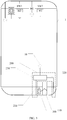
- FIG. 1 is a schematic view of a mobile terminal according to an example not forming part of the claimed invention.
- the mobile terminal 1 includes an external interface body 100, an antenna assembly 200, and a first filter unit 300.
- the antenna assembly 200 includes a first antenna 210, a second antenna 220, and a diplexer 230.
- the external interface body 100 is disposed in an antenna clearance area defined by the first antenna 210 and the second antenna 220.
- the diplexer 230 is connected to the first antenna 210, the second antenna 220, and a feed 10 of a board of the mobile terminal 1.
- the mobile terminal 1 includes four sides, such as top, bottom, left, and right sides.
- the external interface body 100 and the antenna assembly 200 may be disposed at the same side of the mobile terminal 1, for example, the same side may be the top side or the bottom side of the mobile terminal 1.
- the external interface body 100 and the antenna assembly 200 are for example disposed at the bottom side of the mobile terminal 1.
- the first antenna 210, the second antenna 220, and the external interface body 100 are disposed at the bottom side of the mobile terminal 1.
- the first antenna 210 and the second antenna 220 may include a wide range of antennas.
- the first antenna 210 may be a low frequency antenna and the second antenna 220 may be a mid-high frequency antenna.
- a frequency range of the first antenna 210 may be in a range of 824 MHz to 960 MHz and a frequency range of the second antenna 220 may be in a range of 1710 MHz to 2690 MHz.
- the diplexer 230 may be disposed at a top of the external interface body 100.
- the diplexer 230 may be disposed above the external interface body 100 and the diplexer 230 is adjacent to the external interface body 100.
- first antenna 210 and the second antenna 220 are connected to the feed 10 of the board of the mobile terminal 1 via the diplexer 230.
- the diplexer 230 may combine signals received by the first antenna 210 and the second antenna 220.
- the first filter unit 300 is disposed between the first antenna 210 and the external interface body 100 and is connected to a first circuit element 111 (best seen in FIG. 2 ) of the external interface body 100 to reduce interference from the external interface body 100 to the antenna assembly 200.
- the first circuit element 111 may be a microphone pin, a detection pin, or a ground pin.
- the first circuit element may be disposed according to a plurality of positions.
- the first circuit element may be disposed between the external interface body 100 and the diplexer 230.
- the first circuit element may be disposed between the first antenna 210 and the external interface body 100.
- the first circuit element may be disposed between the first antenna 210 and the external interface body 100.
- the first circuit element may be, for example, a pin disposed in the antenna clearance area.
- FIG. 2 is a schematic view illustrating the first filter unit 300 in connection between the ground of the board and the first circuit element 111.
- FIG. 2 is also a partially schematic view of the first filter unit 300 according to an embodiment of the present disclosure.
- the first filter unit 300 includes a capacitor C1 and an inductor LI, an end of the inductor L1 is connected to the first circuit element 111, another end of the inductor L1 is connected to an end of the capacitor C1, and another end of the capacitor C1 is connected to the ground of the board.
- the first circuit element 111 of the external interface body 100 disposed in the antenna clearance area is near to and connected in series with the first filter unit 300, therefore the first filter unit 300 can cut off a radio frequency of an adjacent antenna with large radiation power coupled to the external interface body 100.
- the adjacent antenna may be a global system for mobile communications (GSM) antenna.
- GSM global system for mobile communications
- the external interface body 100 forms a suspension body and thus reduces influence of the external interface body 100 to the antenna.
- Parasitic current which may interfere with audio signal and charging signal, etc., is filtered by the first filter unit 300 and flows to the ground, thus preventing antenna radiation from coupling to a RF signal of the external interface body 100, causing interference to audio and charging to be improved.
- the external interface body 100 is an earphone socket and the mobile terminal in the embodiments of the present disclosure will be further described in detail in combination with FIG. 4 to FIG. 5 hereinafter.
- FIG. 3 is a schematic view of a mobile terminal according to another example not forming part of the claimed invention.
- the mobile terminal 1 includes an earphone socket 110, the antenna assembly 200, and the first filter unit 300.
- the antenna assembly 200 includes the first antenna 210, the second antenna 220, and the diplexer 230.
- the earphone socket 110 is disposed in the antenna clearance area defined by the first antenna 210 and the second antenna 220.
- the first antenna 210 is disposed on a side of the earphone socket 110 and the second antenna 220 is disposed on another side of the earphone socket 110.
- the diplexer 230 is connected to the first antenna 210, the second antenna 220, and the feed 10 of the board of the mobile terminal 1.
- the diplexer 230 may be disposed at a top of the earphone socket 110.
- the first antenna 210 and the second antenna 220 may include a wide range of antennas.
- the first antenna 210 may be a low frequency antenna and the second antenna 220 may be a mid-high frequency antenna.
- a frequency range of the first antenna 210 may be in a range of 824 MHz to 960 MHz and a frequency range of the second antenna 220 may be in a range of 1710 MHz to 2690 MHz.
- the first filter unit 300 is disposed between the first antenna 210 and the earphone socket 110 and is connected to a first circuit element (not labeled) of the earphone socket 110 to reduce interference from the earphone socket 110 to the antenna assembly 200.
- the mobile terminal further includes a second filter unit 400 disposed between the second antenna 220 and the earphone socket 110.
- the second filter unit 400 is connected to a second circuit element (not labeled) of the earphone socket 110 to reduce interference from the earphone socket 110 to the antenna assembly 200.
- the second circuit element is disposed between the second antenna 220 and the earphone socket 110.
- the second filter unit 400 is connected to the ground of the board.
- the second circuit element may be a microphone pin, a detection pin or a ground pin.
- the second circuit element may be disposed between the second antenna 220 and the earphone socket 110.
- the second circuit element may be for example a pin disposed in the antenna clearance area.
- a plurality of circuit boards (i.e., pins) of the earphone socket 110 fall into the antenna clearance area
- a corresponding number of filter units may be corresponding to a number of the pins falling into the antenna clearance area.
- Position and structure of the filter units are similar to those of the first filter unit 300 and the second filter unit 400, but objects to be connected are different.
- the mobile terminal 1 may further include a fingerprint assembly 500.
- the first antenna 210 may be disposed between the fingerprint assembly 500 and the earphone socket 110.
- the fingerprint assembly 500 may be a front fingerprint module of the mobile terminal 1.
- the fingerprint assembly 500 may be disposed just below a front of the mobile terminal 1.
- the fingerprint assembly 500 may be used to acquire and identify a user's fingerprint.
- the user's fingerprint is identified by the fingerprint assembly 500 and various functions such as fingerprint unlock, fingerprint payment, etc. can be realized by the user's fingerprint.
- the first antenna 210 is disposed on a side of the earphone socket 110 and the second antenna 220 is disposed on another side of the earphone socket 110.
- the diplexer 230 is connected to the first antenna 210, the second antenna 220, and the feed 10 of the board of the mobile terminal 1.
- the first filter unit 300 is disposed between the first antenna 210 and the earphone socket 110 and is connected to a first circuit element (not labeled) of the earphone socket 110.
- a circuit board of the earphone socket 110 is near to and connected in series with a filter unit, therefore the filter unit can cut off a radio frequency of an adjacent antenna (e.g., a GSM antenna) with large radiation power coupled to the earphone socket 110.
- an adjacent antenna e.g., a GSM antenna
- the earphone socket 110 forms a suspension body and thus reduces influence of the earphone socket 110 to the antenna.
- Parasitic current which may interfere with audio, is filtered by the filter unit and flows to the ground, thus preventing antenna radiation from coupling to a RF signal of the earphone socket 110, causing interference to audio to be improved.
- the external interface body 100 is a universal serial bus (USB) interface body and the mobile terminal in the example will be further described in detail in combination with FIG. 6 hereinafter.
- USB universal serial bus
- FIG. 6 is a schematic view of a mobile terminal according to still another example not forming par of the claimed invention.
- the mobile terminal 1 includes a USB interface body 120, the antenna assembly 200, and the first filter unit 300.
- the antenna assembly 200 includes the first antenna 210, the second antenna 220, and the diplexer 230.
- the USB interface body 120 is disposed in the antenna clearance area defined by the first antenna 210 and the second antenna 220.
- the second antenna 220 is disposed on a side of the USB interface body 120 and the first antenna 210 is disposed between the USB interface body 120 and the second antenna 220.
- the diplexer 230 is connected to the first antenna 210, the second antenna 220, and the feed 10 of the board of the mobile terminal 1.
- the diplexer 230 may be disposed at a top of the USB interface body 120.
- the first antenna 210 and the second antenna 220 may include a wide range of antennas.
- the first antenna 210 may be a low frequency antenna and the second antenna 220 may be a mid-high frequency antenna.
- a frequency range of the first antenna 210 may be in a range of 824 MHz to 960 MHz and a frequency range of the second antenna 220 may be in a range of 1710 MHz to 2690 MHz.
- the first filter unit 300 is disposed between the first antenna 210 and the USB interface body 120 and is connected to a first circuit element (not labeled) of the USB interface body 120 to reduce interference from the USB interface body 120 to the antenna assembly 200.
- the first circuit element may be a microphone pin, a detection pin, or a ground pin.
- the first filter unit 300 may be near to and connected in series with a pin of the USB interface body 120, and the pin is for example disposed in the antenna clearance area.
- the first filter unit 300 is connected to a ground of the board.
- FIG. 2 is a schematic view illustrating the first filter unit 300 in connection between the ground of the board and the first circuit element 111 and a partially schematic view of the first filter unit 300 according to an embodiment of the present disclosure.
- the first filter unit 300 includes a capacitor C1 and an inductor LI, an end of the inductor L1 is connected to the first circuit element 111, another end of the inductor L1 is connected to an end of the capacitor C1, and another end of the capacitor C1 is connected to the ground of the board.
- the mobile terminal 1 further includes a fingerprint assembly, and the USB interface body 120 may be disposed above a fingerprint tray 510 of the fingerprint assembly.
- a circuit board of the USB interface body 120 disposed in the antenna clearance area is near to and connected in series with the first filter unit 300, therefore the first filter unit 300 can cut off radio frequency of an adjacent antenna (e.g., a GSM antenna) with large radiation power coupled to the USB interface body 120.
- the USB interface body 120 forms a suspension body and thus reduces influence of the USB interface body 120 to the antenna.
- Parasitic current which may interfere with charging signal, is filtered by the first filter unit 300 and flows to the ground, thus preventing antenna radiation from coupling to a RF signal of the USB interface body 120, causing interference to charging and data transmission, etc. to be improved.
- a structure in which a first feature is "on" a second feature may include an embodiment in which the first feature directly contacts the second feature, and may also include an embodiment in which an additional feature is formed between the first feature and the second feature so that the first feature does not directly contact the second feature.
- a first feature "on,” “above,” or “on top of' a second feature may include an embodiment in which the first feature is right “on,” “above,” or “on top of' the second feature, and may also include an embodiment in which the first feature is not right “on,” “above,” or “on top of' the second feature, or just means that the first feature has a sea level elevation greater than the sea level elevation of the second feature.
- first feature "beneath,” “below,” or “on bottom of' a second feature may include an embodiment in which the first feature is right “beneath,” “below,” or “on bottom of' the second feature, and may also include an embodiment in which the first feature is not right “beneath,” “below,” or “on bottom of' the second feature, or just means that the first feature has a sea level elevation less than the sea level elevation of the second feature.
Landscapes
- Engineering & Computer Science (AREA)
- Signal Processing (AREA)
- Computer Networks & Wireless Communication (AREA)
- Telephone Set Structure (AREA)
- Support Of Aerials (AREA)
Claims (11)
- Mobiles Endgerät (1), umfassend:einen Körper (100) für eine externe Schnittstelle, wobei es sich um eine Kopfhörerbuchse (110) handelt;eine Platine, wobei die Platine eine Einspeisung (10) und eine Masse umfasst;eine Antennenanordnung (200), umfassend:eine erste Antenne (210) und eine zweite Antenne (220), wobei der Körper (100) für die externe Schnittstelle in einem durch die erste Antenne (210) und die zweite Antenne (220) definierten Antennenfreiraumbereich eingerichtet ist; undeine erste Filtereinheit (300), die zwischen der ersten Antenne (210) und dem Körper (100) für die externe Schnittstelle eingerichtet ist,dadurch gekennzeichnet, dassdie Antennenanordnung (200) ferner einen Diplexer (230) umfasst, der mit der ersten Antenne (210), der zweiten Antenne (220) und der Einspeisung (10) der Platine des mobilen Endgeräts (1) verbunden ist; unddie erste Filtereinheit (300) in Reihe zwischen die Masse der Platine des mobilen Endgeräts und ein erstes Schaltungselement (111) des Körpers (100) für die externe Schnittstelle geschaltet ist, wobei das erste Schaltungselement (111) ein Stift des Körpers (100) für die externe Schnittstelle ist und zwischen der ersten Antenne (210) und dem Körper (100) für die externe Schnittstelle, zwischen dem Diplexer (230) und dem Körper (100) für die externe Schnittstelle und im Antennenfreiraumbereich eingerichtet ist,wobei die erste Filtereinheit (300) derart ausgelegt ist, dass der Körper (100) für die externe Schnittstelle einen Aufhängungskörper bildet, zu dem Zweck, Störungen vom Körper (100) für die externe Schnittstelle zur Antennenanordnung (200) zu reduzieren,die erste Antenne (210) auf einer Seite der Kopfhörerbuchse (110) eingerichtet ist und die zweite Antenne (220) auf einer anderen Seite der Kopfhörerbuchse (110) eingerichtet ist,das mobile Endgerät eine zweite Filtereinheit (400) umfasst, die zwischen der zweiten Antenne (220) undder Kopfhörerbuchse (110) eingerichtet ist, wobei die zweite Filtereinheit (400) mit einem zweiten Schaltungselement der Kopfhörerbuchse (110) verbunden und dafür ausgelegt ist, Störungen von der Kopfhörerbuchse (110) zur Antennenanordnung (200) zu reduzieren.
- Mobiles Endgerät nach Anspruch 1, dadurch gekennzeichnet, dass die erste Filtereinheit (300) einen Kondensator (C1) und einen Induktor (L1) umfasst, wobei ein Ende des Induktors (L1) mit dem ersten Schaltungselement (111) verbunden ist, ein anderes Ende des Induktors (L1) mit einem Ende des Kondensators (C1) verbunden ist, und ein anderes Ende des Kondensators (C1) mit der Masse der Platine verbunden ist.
- Mobiles Endgerät nach Anspruch 1, dadurch gekennzeichnet, dass die Kopfhörerbuchse (110) eine Vielzahl von Stiften im Antennenfreiraumbereich umfasst.
- Mobiles Endgerät nach Anspruch 3, dadurch gekennzeichnet, dass es ferner weitere Filtereinheiten umfasst, wobei eine Anzahl der Filtereinheiten einer Anzahl der Stifte der Kopfhörerbuchse (110) entspricht.
- Mobiles Endgerät nach Anspruch 1, dadurch gekennzeichnet, dass das zweite Schaltungselement zwischen der zweiten Antenne (220) und der Kopfhörerbuchse (110) eingerichtet ist.
- Mobiles Endgerät nach Anspruch 5, dadurch gekennzeichnet, dass der Diplexer (230) an der Oberseite des Körpers (100) für die externe Schnittstelle eingerichtet ist.
- Mobiles Endgerät nach Anspruch 1, dadurch gekennzeichnet, dass die erste Antenne (210) eine Niederfrequenzantenne und die zweite Antenne (220) eine Mittel-Hoch-Frequenzantenne ist.
- Mobiles Endgerät nach Anspruch 1, dadurch gekennzeichnet, dass es ferner eine Fingerabdruckanordnung umfasst, wobei die erste Antenne (210) zwischen der Fingerabdruckanordnung und der Kopfhörerbuchse (110) eingerichtet ist.
- Mobiles Endgerät nach Anspruch 1, dadurch gekennzeichnet, dass die zweite Filtereinheit (400) mit einer Masse der Platine verbunden ist.
- Mobiles Endgerät nach Anspruch 1, dadurch gekennzeichnet, dass ein Frequenzbereich der ersten Antenne (210) in einem Bereich von 824 MHz bis 960 MHz liegt und ein Frequenzbereich der zweiten Antenne (220) in einem Bereich von 1710 MHz bis 2690 MHz liegt.
- Mobiles Endgerät nach Anspruch 1, dadurch gekennzeichnet, dass der Diplexer (230) oberhalb des Körpers (100) für die externe Schnittstelle eingerichtet ist und der Diplexer (230) dem Körper (100) für die externe Schnittstelle benachbart ist.
Applications Claiming Priority (2)
| Application Number | Priority Date | Filing Date | Title |
|---|---|---|---|
| CN201611118262.3A CN106657467B (zh) | 2016-12-07 | 2016-12-07 | 移动终端 |
| CN201621340998.0U CN206251152U (zh) | 2016-12-07 | 2016-12-07 | 移动终端 |
Publications (2)
| Publication Number | Publication Date |
|---|---|
| EP3333973A1 EP3333973A1 (de) | 2018-06-13 |
| EP3333973B1 true EP3333973B1 (de) | 2021-11-03 |
Family
ID=60327166
Family Applications (1)
| Application Number | Title | Priority Date | Filing Date |
|---|---|---|---|
| EP17201678.4A Active EP3333973B1 (de) | 2016-12-07 | 2017-11-14 | Mobiles endgerät |
Country Status (3)
| Country | Link |
|---|---|
| US (1) | US10211518B2 (de) |
| EP (1) | EP3333973B1 (de) |
| WO (1) | WO2018103506A1 (de) |
Families Citing this family (2)
| Publication number | Priority date | Publication date | Assignee | Title |
|---|---|---|---|---|
| CN104577334B (zh) * | 2015-02-11 | 2017-07-21 | 小米科技有限责任公司 | 天线模块及移动终端 |
| US12249774B2 (en) | 2022-07-25 | 2025-03-11 | Shure Acquisition Holdings, Inc. | Dual band plug-on transmitter antenna |
Family Cites Families (16)
| Publication number | Priority date | Publication date | Assignee | Title |
|---|---|---|---|---|
| KR101221592B1 (ko) * | 2006-10-02 | 2013-01-14 | 삼성전자주식회사 | 안테나 겸용 근거리 무선통신 모듈 및 그를 갖는 휴대단말기 |
| US8554154B1 (en) * | 2010-03-16 | 2013-10-08 | Sprint Communications Company L.P. | Connector supporting integrated radio frequency and baseband data |
| EP2564470A1 (de) * | 2010-04-28 | 2013-03-06 | Telefonaktiebolaget LM Ericsson (publ) | Kommunikationsvorrichtung mit zwei oder mehreren antennen |
| KR20120050620A (ko) * | 2010-11-11 | 2012-05-21 | 삼성전자주식회사 | 다중 공진 안테나를 이용하여 다중 대역들의 신호를 수신하는 휴대단말 장치 |
| US8639194B2 (en) * | 2011-09-28 | 2014-01-28 | Motorola Mobility Llc | Tunable antenna with a conductive, physical component co-located with the antenna |
| CN102856629B (zh) | 2012-08-31 | 2015-09-23 | 惠州Tcl移动通信有限公司 | 一种手机三合一天线装置 |
| US9716307B2 (en) * | 2012-11-08 | 2017-07-25 | Htc Corporation | Mobile device and antenna structure |
| US9160825B2 (en) | 2013-10-30 | 2015-10-13 | Taiyo Yuden Co., Ltd. | Communication module |
| KR102094754B1 (ko) * | 2013-12-03 | 2020-03-30 | 엘지전자 주식회사 | 이동 단말기 |
| US9577318B2 (en) * | 2014-08-19 | 2017-02-21 | Apple Inc. | Electronic device with fingerprint sensor and tunable hybrid antenna |
| KR102178485B1 (ko) * | 2014-08-21 | 2020-11-13 | 삼성전자주식회사 | 안테나 장치 및 그것을 포함하는 전자 장치 |
| KR102226173B1 (ko) * | 2014-09-02 | 2021-03-10 | 삼성전자주식회사 | 외부 금속 프레임을 이용한 안테나 및 이를 구비한 전자 장치 |
| US9647332B2 (en) * | 2014-09-03 | 2017-05-09 | Apple Inc. | Electronic device antenna with interference mitigation circuitry |
| CN105514604B (zh) | 2015-12-09 | 2018-09-11 | 广东欧珀移动通信有限公司 | 移动终端 |
| CN206251152U (zh) | 2016-12-07 | 2017-06-13 | 广东欧珀移动通信有限公司 | 移动终端 |
| CN106657467B (zh) | 2016-12-07 | 2021-07-09 | Oppo广东移动通信有限公司 | 移动终端 |
-
2017
- 2017-10-19 US US15/787,858 patent/US10211518B2/en active Active
- 2017-11-13 WO PCT/CN2017/110712 patent/WO2018103506A1/en not_active Ceased
- 2017-11-14 EP EP17201678.4A patent/EP3333973B1/de active Active
Non-Patent Citations (1)
| Title |
|---|
| None * |
Also Published As
| Publication number | Publication date |
|---|---|
| US20180159205A1 (en) | 2018-06-07 |
| US10211518B2 (en) | 2019-02-19 |
| EP3333973A1 (de) | 2018-06-13 |
| WO2018103506A1 (en) | 2018-06-14 |
Similar Documents
| Publication | Publication Date | Title |
|---|---|---|
| US10033113B2 (en) | Antenna device and electronic apparatus | |
| CN106550073B (zh) | 应用于移动终端的设备组件及移动终端 | |
| US8818470B2 (en) | Mobile communication device | |
| CN106657467B (zh) | 移动终端 | |
| CN108292798A (zh) | 低剖面天线装置 | |
| EP3167509B1 (de) | Vorrichtung und verfahren zur drahtlosen kommunikation | |
| US9686385B2 (en) | Apparatus for wireless communication | |
| CN106252881B (zh) | 天线装置及移动终端 | |
| CN106450697A (zh) | 一种电子设备的天线装置及电子设备 | |
| WO2015166800A1 (ja) | 端末装置 | |
| JP2015023394A (ja) | 無線モジュール | |
| EP3333973B1 (de) | Mobiles endgerät | |
| US9191471B2 (en) | Wireless communication device | |
| CN107526702B (zh) | 一种移动终端的usb接口电路及具有该电路的移动终端 | |
| CN104795625A (zh) | 包含距离感应器的天线结构 | |
| WO2018031312A1 (en) | Test rf connector | |
| EP3333972B1 (de) | An einem mobilen endgerät angewandte vorrichtungsanordnung und mobiles endgerät | |
| TW201528605A (zh) | 具接近感應器的天線結構 | |
| US9385421B2 (en) | Antenna and electronic device for close proximity wireless communication | |
| US11777218B2 (en) | Antenna design with structurally integrated composite antenna components | |
| CN107895844B (zh) | 一种天线组合结构及移动终端 | |
| CN206251152U (zh) | 移动终端 | |
| CN110086494A (zh) | 车用无线通信装置、车辆无线通信方法 | |
| JP2017069608A (ja) | 通信装置 | |
| CN210576413U (zh) | 电子设备 |
Legal Events
| Date | Code | Title | Description |
|---|---|---|---|
| PUAI | Public reference made under article 153(3) epc to a published international application that has entered the european phase |
Free format text: ORIGINAL CODE: 0009012 |
|
| STAA | Information on the status of an ep patent application or granted ep patent |
Free format text: STATUS: REQUEST FOR EXAMINATION WAS MADE |
|
| 17P | Request for examination filed |
Effective date: 20171114 |
|
| AK | Designated contracting states |
Kind code of ref document: A1 Designated state(s): AL AT BE BG CH CY CZ DE DK EE ES FI FR GB GR HR HU IE IS IT LI LT LU LV MC MK MT NL NO PL PT RO RS SE SI SK SM TR |
|
| AX | Request for extension of the european patent |
Extension state: BA ME |
|
| RAP1 | Party data changed (applicant data changed or rights of an application transferred) |
Owner name: GUANGDONG OPPO MOBILE TELECOMMUNICATIONS CORP., LT |
|
| STAA | Information on the status of an ep patent application or granted ep patent |
Free format text: STATUS: EXAMINATION IS IN PROGRESS |
|
| 17Q | First examination report despatched |
Effective date: 20200213 |
|
| GRAP | Despatch of communication of intention to grant a patent |
Free format text: ORIGINAL CODE: EPIDOSNIGR1 |
|
| STAA | Information on the status of an ep patent application or granted ep patent |
Free format text: STATUS: GRANT OF PATENT IS INTENDED |
|
| INTG | Intention to grant announced |
Effective date: 20210723 |
|
| GRAS | Grant fee paid |
Free format text: ORIGINAL CODE: EPIDOSNIGR3 |
|
| GRAA | (expected) grant |
Free format text: ORIGINAL CODE: 0009210 |
|
| STAA | Information on the status of an ep patent application or granted ep patent |
Free format text: STATUS: THE PATENT HAS BEEN GRANTED |
|
| AK | Designated contracting states |
Kind code of ref document: B1 Designated state(s): AL AT BE BG CH CY CZ DE DK EE ES FI FR GB GR HR HU IE IS IT LI LT LU LV MC MK MT NL NO PL PT RO RS SE SI SK SM TR |
|
| REG | Reference to a national code |
Ref country code: GB Ref legal event code: FG4D |
|
| REG | Reference to a national code |
Ref country code: AT Ref legal event code: REF Ref document number: 1444813 Country of ref document: AT Kind code of ref document: T Effective date: 20211115 Ref country code: CH Ref legal event code: EP |
|
| REG | Reference to a national code |
Ref country code: IE Ref legal event code: FG4D |
|
| REG | Reference to a national code |
Ref country code: DE Ref legal event code: R096 Ref document number: 602017048630 Country of ref document: DE |
|
| REG | Reference to a national code |
Ref country code: LT Ref legal event code: MG9D |
|
| REG | Reference to a national code |
Ref country code: NL Ref legal event code: MP Effective date: 20211103 |
|
| REG | Reference to a national code |
Ref country code: AT Ref legal event code: MK05 Ref document number: 1444813 Country of ref document: AT Kind code of ref document: T Effective date: 20211103 |
|
| PG25 | Lapsed in a contracting state [announced via postgrant information from national office to epo] |
Ref country code: RS Free format text: LAPSE BECAUSE OF FAILURE TO SUBMIT A TRANSLATION OF THE DESCRIPTION OR TO PAY THE FEE WITHIN THE PRESCRIBED TIME-LIMIT Effective date: 20211103 Ref country code: LT Free format text: LAPSE BECAUSE OF FAILURE TO SUBMIT A TRANSLATION OF THE DESCRIPTION OR TO PAY THE FEE WITHIN THE PRESCRIBED TIME-LIMIT Effective date: 20211103 Ref country code: FI Free format text: LAPSE BECAUSE OF FAILURE TO SUBMIT A TRANSLATION OF THE DESCRIPTION OR TO PAY THE FEE WITHIN THE PRESCRIBED TIME-LIMIT Effective date: 20211103 Ref country code: BG Free format text: LAPSE BECAUSE OF FAILURE TO SUBMIT A TRANSLATION OF THE DESCRIPTION OR TO PAY THE FEE WITHIN THE PRESCRIBED TIME-LIMIT Effective date: 20220203 Ref country code: AT Free format text: LAPSE BECAUSE OF FAILURE TO SUBMIT A TRANSLATION OF THE DESCRIPTION OR TO PAY THE FEE WITHIN THE PRESCRIBED TIME-LIMIT Effective date: 20211103 |
|
| PG25 | Lapsed in a contracting state [announced via postgrant information from national office to epo] |
Ref country code: IS Free format text: LAPSE BECAUSE OF FAILURE TO SUBMIT A TRANSLATION OF THE DESCRIPTION OR TO PAY THE FEE WITHIN THE PRESCRIBED TIME-LIMIT Effective date: 20220303 Ref country code: SE Free format text: LAPSE BECAUSE OF FAILURE TO SUBMIT A TRANSLATION OF THE DESCRIPTION OR TO PAY THE FEE WITHIN THE PRESCRIBED TIME-LIMIT Effective date: 20211103 Ref country code: PT Free format text: LAPSE BECAUSE OF FAILURE TO SUBMIT A TRANSLATION OF THE DESCRIPTION OR TO PAY THE FEE WITHIN THE PRESCRIBED TIME-LIMIT Effective date: 20220303 Ref country code: PL Free format text: LAPSE BECAUSE OF FAILURE TO SUBMIT A TRANSLATION OF THE DESCRIPTION OR TO PAY THE FEE WITHIN THE PRESCRIBED TIME-LIMIT Effective date: 20211103 Ref country code: NO Free format text: LAPSE BECAUSE OF FAILURE TO SUBMIT A TRANSLATION OF THE DESCRIPTION OR TO PAY THE FEE WITHIN THE PRESCRIBED TIME-LIMIT Effective date: 20220203 Ref country code: NL Free format text: LAPSE BECAUSE OF FAILURE TO SUBMIT A TRANSLATION OF THE DESCRIPTION OR TO PAY THE FEE WITHIN THE PRESCRIBED TIME-LIMIT Effective date: 20211103 Ref country code: LV Free format text: LAPSE BECAUSE OF FAILURE TO SUBMIT A TRANSLATION OF THE DESCRIPTION OR TO PAY THE FEE WITHIN THE PRESCRIBED TIME-LIMIT Effective date: 20211103 Ref country code: HR Free format text: LAPSE BECAUSE OF FAILURE TO SUBMIT A TRANSLATION OF THE DESCRIPTION OR TO PAY THE FEE WITHIN THE PRESCRIBED TIME-LIMIT Effective date: 20211103 Ref country code: GR Free format text: LAPSE BECAUSE OF FAILURE TO SUBMIT A TRANSLATION OF THE DESCRIPTION OR TO PAY THE FEE WITHIN THE PRESCRIBED TIME-LIMIT Effective date: 20220204 Ref country code: ES Free format text: LAPSE BECAUSE OF FAILURE TO SUBMIT A TRANSLATION OF THE DESCRIPTION OR TO PAY THE FEE WITHIN THE PRESCRIBED TIME-LIMIT Effective date: 20211103 |
|
| REG | Reference to a national code |
Ref country code: CH Ref legal event code: PL |
|
| PG25 | Lapsed in a contracting state [announced via postgrant information from national office to epo] |
Ref country code: SM Free format text: LAPSE BECAUSE OF FAILURE TO SUBMIT A TRANSLATION OF THE DESCRIPTION OR TO PAY THE FEE WITHIN THE PRESCRIBED TIME-LIMIT Effective date: 20211103 Ref country code: SK Free format text: LAPSE BECAUSE OF FAILURE TO SUBMIT A TRANSLATION OF THE DESCRIPTION OR TO PAY THE FEE WITHIN THE PRESCRIBED TIME-LIMIT Effective date: 20211103 Ref country code: RO Free format text: LAPSE BECAUSE OF FAILURE TO SUBMIT A TRANSLATION OF THE DESCRIPTION OR TO PAY THE FEE WITHIN THE PRESCRIBED TIME-LIMIT Effective date: 20211103 Ref country code: LU Free format text: LAPSE BECAUSE OF NON-PAYMENT OF DUE FEES Effective date: 20211114 Ref country code: EE Free format text: LAPSE BECAUSE OF FAILURE TO SUBMIT A TRANSLATION OF THE DESCRIPTION OR TO PAY THE FEE WITHIN THE PRESCRIBED TIME-LIMIT Effective date: 20211103 Ref country code: DK Free format text: LAPSE BECAUSE OF FAILURE TO SUBMIT A TRANSLATION OF THE DESCRIPTION OR TO PAY THE FEE WITHIN THE PRESCRIBED TIME-LIMIT Effective date: 20211103 Ref country code: CZ Free format text: LAPSE BECAUSE OF FAILURE TO SUBMIT A TRANSLATION OF THE DESCRIPTION OR TO PAY THE FEE WITHIN THE PRESCRIBED TIME-LIMIT Effective date: 20211103 Ref country code: BE Free format text: LAPSE BECAUSE OF NON-PAYMENT OF DUE FEES Effective date: 20211130 |
|
| REG | Reference to a national code |
Ref country code: BE Ref legal event code: MM Effective date: 20211130 |
|
| REG | Reference to a national code |
Ref country code: DE Ref legal event code: R097 Ref document number: 602017048630 Country of ref document: DE |
|
| PG25 | Lapsed in a contracting state [announced via postgrant information from national office to epo] |
Ref country code: MC Free format text: LAPSE BECAUSE OF FAILURE TO SUBMIT A TRANSLATION OF THE DESCRIPTION OR TO PAY THE FEE WITHIN THE PRESCRIBED TIME-LIMIT Effective date: 20211103 |
|
| PLBE | No opposition filed within time limit |
Free format text: ORIGINAL CODE: 0009261 |
|
| STAA | Information on the status of an ep patent application or granted ep patent |
Free format text: STATUS: NO OPPOSITION FILED WITHIN TIME LIMIT |
|
| 26N | No opposition filed |
Effective date: 20220804 |
|
| PG25 | Lapsed in a contracting state [announced via postgrant information from national office to epo] |
Ref country code: IE Free format text: LAPSE BECAUSE OF NON-PAYMENT OF DUE FEES Effective date: 20211114 Ref country code: AL Free format text: LAPSE BECAUSE OF FAILURE TO SUBMIT A TRANSLATION OF THE DESCRIPTION OR TO PAY THE FEE WITHIN THE PRESCRIBED TIME-LIMIT Effective date: 20211103 |
|
| PG25 | Lapsed in a contracting state [announced via postgrant information from national office to epo] |
Ref country code: SI Free format text: LAPSE BECAUSE OF FAILURE TO SUBMIT A TRANSLATION OF THE DESCRIPTION OR TO PAY THE FEE WITHIN THE PRESCRIBED TIME-LIMIT Effective date: 20211103 |
|
| PG25 | Lapsed in a contracting state [announced via postgrant information from national office to epo] |
Ref country code: IT Free format text: LAPSE BECAUSE OF FAILURE TO SUBMIT A TRANSLATION OF THE DESCRIPTION OR TO PAY THE FEE WITHIN THE PRESCRIBED TIME-LIMIT Effective date: 20211103 Ref country code: HU Free format text: LAPSE BECAUSE OF FAILURE TO SUBMIT A TRANSLATION OF THE DESCRIPTION OR TO PAY THE FEE WITHIN THE PRESCRIBED TIME-LIMIT; INVALID AB INITIO Effective date: 20171114 |
|
| P01 | Opt-out of the competence of the unified patent court (upc) registered |
Effective date: 20230412 |
|
| PG25 | Lapsed in a contracting state [announced via postgrant information from national office to epo] |
Ref country code: CY Free format text: LAPSE BECAUSE OF FAILURE TO SUBMIT A TRANSLATION OF THE DESCRIPTION OR TO PAY THE FEE WITHIN THE PRESCRIBED TIME-LIMIT Effective date: 20211103 |
|
| PG25 | Lapsed in a contracting state [announced via postgrant information from national office to epo] |
Ref country code: LI Free format text: LAPSE BECAUSE OF NON-PAYMENT OF DUE FEES Effective date: 20220701 Ref country code: CH Free format text: LAPSE BECAUSE OF NON-PAYMENT OF DUE FEES Effective date: 20220701 |
|
| PG25 | Lapsed in a contracting state [announced via postgrant information from national office to epo] |
Ref country code: MK Free format text: LAPSE BECAUSE OF FAILURE TO SUBMIT A TRANSLATION OF THE DESCRIPTION OR TO PAY THE FEE WITHIN THE PRESCRIBED TIME-LIMIT Effective date: 20211103 |
|
| PG25 | Lapsed in a contracting state [announced via postgrant information from national office to epo] |
Ref country code: TR Free format text: LAPSE BECAUSE OF FAILURE TO SUBMIT A TRANSLATION OF THE DESCRIPTION OR TO PAY THE FEE WITHIN THE PRESCRIBED TIME-LIMIT Effective date: 20211103 |
|
| PG25 | Lapsed in a contracting state [announced via postgrant information from national office to epo] |
Ref country code: MT Free format text: LAPSE BECAUSE OF FAILURE TO SUBMIT A TRANSLATION OF THE DESCRIPTION OR TO PAY THE FEE WITHIN THE PRESCRIBED TIME-LIMIT Effective date: 20211103 |
|
| PGFP | Annual fee paid to national office [announced via postgrant information from national office to epo] |
Ref country code: DE Payment date: 20251124 Year of fee payment: 9 |
|
| PGFP | Annual fee paid to national office [announced via postgrant information from national office to epo] |
Ref country code: GB Payment date: 20251126 Year of fee payment: 9 |
|
| PGFP | Annual fee paid to national office [announced via postgrant information from national office to epo] |
Ref country code: FR Payment date: 20251126 Year of fee payment: 9 |