EP3333940A1 - Secondary battery - Google Patents
Secondary battery Download PDFInfo
- Publication number
- EP3333940A1 EP3333940A1 EP17834707.6A EP17834707A EP3333940A1 EP 3333940 A1 EP3333940 A1 EP 3333940A1 EP 17834707 A EP17834707 A EP 17834707A EP 3333940 A1 EP3333940 A1 EP 3333940A1
- Authority
- EP
- European Patent Office
- Prior art keywords
- ground
- secondary battery
- electrode
- disposed
- ground member
- Prior art date
- Legal status (The legal status is an assumption and is not a legal conclusion. Google has not performed a legal analysis and makes no representation as to the accuracy of the status listed.)
- Granted
Links
- 230000002159 abnormal effect Effects 0.000 claims abstract description 17
- 239000000463 material Substances 0.000 claims description 5
- RYGMFSIKBFXOCR-UHFFFAOYSA-N Copper Chemical compound [Cu] RYGMFSIKBFXOCR-UHFFFAOYSA-N 0.000 claims description 2
- XAGFODPZIPBFFR-UHFFFAOYSA-N aluminium Chemical compound [Al] XAGFODPZIPBFFR-UHFFFAOYSA-N 0.000 claims description 2
- 229910052782 aluminium Inorganic materials 0.000 claims description 2
- 239000004020 conductor Substances 0.000 claims description 2
- 229910052802 copper Inorganic materials 0.000 claims description 2
- 239000010949 copper Substances 0.000 claims description 2
- HBBGRARXTFLTSG-UHFFFAOYSA-N Lithium ion Chemical compound [Li+] HBBGRARXTFLTSG-UHFFFAOYSA-N 0.000 description 2
- 239000003792 electrolyte Substances 0.000 description 2
- 239000010408 film Substances 0.000 description 2
- 229910001416 lithium ion Inorganic materials 0.000 description 2
- -1 polyethylene Polymers 0.000 description 2
- 239000000126 substance Substances 0.000 description 2
- WHXSMMKQMYFTQS-UHFFFAOYSA-N Lithium Chemical compound [Li] WHXSMMKQMYFTQS-UHFFFAOYSA-N 0.000 description 1
- 239000004698 Polyethylene Substances 0.000 description 1
- 239000004743 Polypropylene Substances 0.000 description 1
- 239000011149 active material Substances 0.000 description 1
- 239000003990 capacitor Substances 0.000 description 1
- 239000000470 constituent Substances 0.000 description 1
- 230000000694 effects Effects 0.000 description 1
- 238000005516 engineering process Methods 0.000 description 1
- 238000010304 firing Methods 0.000 description 1
- 239000011888 foil Substances 0.000 description 1
- 239000012774 insulation material Substances 0.000 description 1
- 229910052744 lithium Inorganic materials 0.000 description 1
- 238000004519 manufacturing process Methods 0.000 description 1
- 229920000573 polyethylene Polymers 0.000 description 1
- 229920000642 polymer Polymers 0.000 description 1
- 229920005672 polyolefin resin Polymers 0.000 description 1
- 229920001155 polypropylene Polymers 0.000 description 1
- 238000010248 power generation Methods 0.000 description 1
- 238000007789 sealing Methods 0.000 description 1
- 238000000926 separation method Methods 0.000 description 1
- 239000010409 thin film Substances 0.000 description 1
Images


Classifications
-
- H—ELECTRICITY
- H01—ELECTRIC ELEMENTS
- H01M—PROCESSES OR MEANS, e.g. BATTERIES, FOR THE DIRECT CONVERSION OF CHEMICAL ENERGY INTO ELECTRICAL ENERGY
- H01M50/00—Constructional details or processes of manufacture of the non-active parts of electrochemical cells other than fuel cells, e.g. hybrid cells
- H01M50/40—Separators; Membranes; Diaphragms; Spacing elements inside cells
- H01M50/46—Separators, membranes or diaphragms characterised by their combination with electrodes
-
- H—ELECTRICITY
- H01—ELECTRIC ELEMENTS
- H01M—PROCESSES OR MEANS, e.g. BATTERIES, FOR THE DIRECT CONVERSION OF CHEMICAL ENERGY INTO ELECTRICAL ENERGY
- H01M10/00—Secondary cells; Manufacture thereof
- H01M10/04—Construction or manufacture in general
- H01M10/0413—Large-sized flat cells or batteries for motive or stationary systems with plate-like electrodes
-
- H—ELECTRICITY
- H01—ELECTRIC ELEMENTS
- H01M—PROCESSES OR MEANS, e.g. BATTERIES, FOR THE DIRECT CONVERSION OF CHEMICAL ENERGY INTO ELECTRICAL ENERGY
- H01M10/00—Secondary cells; Manufacture thereof
- H01M10/05—Accumulators with non-aqueous electrolyte
- H01M10/058—Construction or manufacture
- H01M10/0585—Construction or manufacture of accumulators having only flat construction elements, i.e. flat positive electrodes, flat negative electrodes and flat separators
-
- H—ELECTRICITY
- H01—ELECTRIC ELEMENTS
- H01M—PROCESSES OR MEANS, e.g. BATTERIES, FOR THE DIRECT CONVERSION OF CHEMICAL ENERGY INTO ELECTRICAL ENERGY
- H01M50/00—Constructional details or processes of manufacture of the non-active parts of electrochemical cells other than fuel cells, e.g. hybrid cells
- H01M50/50—Current conducting connections for cells or batteries
- H01M50/572—Means for preventing undesired use or discharge
-
- H—ELECTRICITY
- H01—ELECTRIC ELEMENTS
- H01M—PROCESSES OR MEANS, e.g. BATTERIES, FOR THE DIRECT CONVERSION OF CHEMICAL ENERGY INTO ELECTRICAL ENERGY
- H01M10/00—Secondary cells; Manufacture thereof
- H01M10/05—Accumulators with non-aqueous electrolyte
- H01M10/052—Li-accumulators
-
- H—ELECTRICITY
- H01—ELECTRIC ELEMENTS
- H01M—PROCESSES OR MEANS, e.g. BATTERIES, FOR THE DIRECT CONVERSION OF CHEMICAL ENERGY INTO ELECTRICAL ENERGY
- H01M2200/00—Safety devices for primary or secondary batteries
-
- H—ELECTRICITY
- H01—ELECTRIC ELEMENTS
- H01M—PROCESSES OR MEANS, e.g. BATTERIES, FOR THE DIRECT CONVERSION OF CHEMICAL ENERGY INTO ELECTRICAL ENERGY
- H01M2220/00—Batteries for particular applications
- H01M2220/20—Batteries in motive systems, e.g. vehicle, ship, plane
-
- H—ELECTRICITY
- H01—ELECTRIC ELEMENTS
- H01M—PROCESSES OR MEANS, e.g. BATTERIES, FOR THE DIRECT CONVERSION OF CHEMICAL ENERGY INTO ELECTRICAL ENERGY
- H01M50/00—Constructional details or processes of manufacture of the non-active parts of electrochemical cells other than fuel cells, e.g. hybrid cells
- H01M50/40—Separators; Membranes; Diaphragms; Spacing elements inside cells
- H01M50/463—Separators, membranes or diaphragms characterised by their shape
-
- Y—GENERAL TAGGING OF NEW TECHNOLOGICAL DEVELOPMENTS; GENERAL TAGGING OF CROSS-SECTIONAL TECHNOLOGIES SPANNING OVER SEVERAL SECTIONS OF THE IPC; TECHNICAL SUBJECTS COVERED BY FORMER USPC CROSS-REFERENCE ART COLLECTIONS [XRACs] AND DIGESTS
- Y02—TECHNOLOGIES OR APPLICATIONS FOR MITIGATION OR ADAPTATION AGAINST CLIMATE CHANGE
- Y02E—REDUCTION OF GREENHOUSE GAS [GHG] EMISSIONS, RELATED TO ENERGY GENERATION, TRANSMISSION OR DISTRIBUTION
- Y02E60/00—Enabling technologies; Technologies with a potential or indirect contribution to GHG emissions mitigation
- Y02E60/10—Energy storage using batteries
-
- Y—GENERAL TAGGING OF NEW TECHNOLOGICAL DEVELOPMENTS; GENERAL TAGGING OF CROSS-SECTIONAL TECHNOLOGIES SPANNING OVER SEVERAL SECTIONS OF THE IPC; TECHNICAL SUBJECTS COVERED BY FORMER USPC CROSS-REFERENCE ART COLLECTIONS [XRACs] AND DIGESTS
- Y02—TECHNOLOGIES OR APPLICATIONS FOR MITIGATION OR ADAPTATION AGAINST CLIMATE CHANGE
- Y02P—CLIMATE CHANGE MITIGATION TECHNOLOGIES IN THE PRODUCTION OR PROCESSING OF GOODS
- Y02P70/00—Climate change mitigation technologies in the production process for final industrial or consumer products
- Y02P70/50—Manufacturing or production processes characterised by the final manufactured product
Definitions
- the present invention relate to a secondary battery.
- Secondary batteries are rechargeable unlike primarily batteries, and also, the possibility of compact size and high capacity is high. Thus, recently, many studies on secondary batteries are being carried out. As technology development and demands for mobile devices increase, the demands for secondary batteries as energy sources are rapidly increasing.
- secondary batteries are classified into coin type batteries, cylindrical type batteries, prismatic type batteries, and pouch type batteries according to a shape of a battery case.
- an electrode assembly mounted in a battery case is a chargeable and dischargeable power generating device having a structure in which an electrode and a separator are stacked.
- the electrode assembly may be approximately classified into a jelly-roll type electrode assembly in which a separator is interposed between a positive electrode and a negative electrode, each of which is provided as the form of a sheet coated with an active material, and then, the positive electrode, the separator, and the negative electrode are wound, a stacked type electrode assembly in which a plurality of positive and negative electrodes with a separator therebetween are sequentially stacked, and a stack/folding type electrode assembly in which stacked type unit cells are wound together with a separation film having a long length.
- pouch-type secondary batteries which are capable of being applied to products such as mobile phones having thin thicknesses in terms of the shapes of the batteries.
- lithium secondary batteries such as lithium ion batteries and lithium ion polymer batteries, which have high energy densities, high discharge voltages, and excellent output safety in terms of the materials of the batteries.
- a middle- or large-sized battery pack in which a plurality of battery cells as unit cells are electrically connected is used, and also, as an increase in capacitive density is required, cells having higher energy per cell are being developed.
- the middle- or large-sized battery pack is necessary to be manufactured so as to have a small size and a light weight, a square shape battery, a pouch shape battery, etc., which may be stacked with high density and light weight when compared with the capacity, are mainly manufactured as the battery cells of the middle- or large-sized battery pack.
- the pouch-type battery having a small weight, low possibility of electrolyte leakage, and a low manufacturing cost is particularly attracting much attention.
- the pouch-type battery is influential as the unit cell of the middle- or large-sized battery pack due to its various advantages.
- a pyrotechnic substance such as an electrolyte leaks to increase the risk of fire when a battery case has low mechanical strength, and a sealing part is separated.
- an external object such as a nail or the like penetrates through the cell
- sudden current flows between the positive electrode and the negative electrode to generate heat, sparks, and the like and thereby to cause outbreak of fire.
- One aspect of the present invention is to provide a secondary battery that is capable of improving safety of the battery against an external impact.
- a secondary battery according to an embodiment of the present invention comprises an electrode stack in which an electrode and a separator are combined with each other and a ground part grounding the electrode stack to the outside, wherein the ground part comprises a ground member disposed at one side of the separator to allow abnormal current flowing from the electrode to the one side of the separator to be introduced therein.
- the abnormal current when the abnormal current flows due to the external impact, the abnormal current may flow to the outside through the ground part to prevent the heat and the sparks from being generated. Therefore, the safety of the battery against the external impact may be improved.
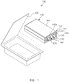
- FIG. 1 is a perspective view of a secondary battery according to an embodiment of the present invention.
- a secondary battery 100 according to an embodiment of the present invention comprises an electrode stack 110 and a ground part 140 grounding the electrode stack 110 to the outside. Also, the secondary battery according to an embodiment of the present invention may comprise a battery case 130 accommodating the electrode stack 110.
- the electrode stack 110 may be a chargeable and dischargeable power generation element and manufactured by combining an electrode 113 with a separator 114.
- the electrode stack 110 may be provided with, for example, a jelly-roll type, a stacked-type, or a stack/folding type.
- the separator 114 may be disposed on each of both surfaces of the electrode 113 or disposed to surround an outer surface of the electrode 113.
- the electrode 113 comprises a positive electrode 111 and a negative electrode 112.
- the electrode stack 110 may have a structure in which the positive electrode 111/the separator 114/the negative electrode 113 are alternately stacked.
- the separator 114 may be disposed between the positive electrode 111 and the negative electrode 112 and disposed outside the positive electrode 111 and outside the negative electrode 112.
- the separator 114 may be disposed to surround the entire electrode stack 110 in which the positive electrode 111/the separator 114/the negative electrode 113 are stacked.
- the separator 114 is made of an insulation material to electrically insulate the positive electrode 111 from the negative electrode 112.
- the separator 114 may be made of, for example, a polyolefin-based resin film such as polyethylene or polypropylene having micropores.
- the electrode stack 110 may comprises a positive electrode terminal 121 and a negative electrode terminal 122.
- the positive electrode terminal 121 may be electrically connected to a side surface of the positive electrode 111
- the negative electrode terminal 122 may be electrically connected to a side surface of the electrode 112.
- the ground part 140 grounds the electrode stack 110 to the outside.
- the ground part 140 may comprise a ground member 141 into which abnormal current of the electrode stack 110 is introduced and a ground line 142 grounding the ground member 141 to the outside.
- the abnormal current introduced into the ground member 141 may flow to the outside of the battery case 130 through the ground part 140.
- the ground member 141 may be disposed at one side of the separator 114 so that the abnormal current flowing from the electrode 113 to one side of the separator 114 is introduced into the ground member 141.
- the ground member 141 may be disposed on the outermost surface of the electrode stack 110 in a stacking direction of the electrode stack 110 so that the abnormal current flowing from the electrode 113 to the outermost surface of the electrode stack 110 is introduced into the ground member 141.
- the separator 114 may be disposed on the outermost portion of the electrode stack 110, and the ground member 141 may be disposed on an outer surface of the separator 114.
- the ground member 141 may be disposed on one or more surfaces of one surface and the other surface of the electrode stack 110 in the stacking direction of the electrode stack 110.
- the ground member 141 may be made of a flexible material.
- the ground member 141 may be provided as a foil or thin film.
- the ground member 141 may have a thickness of 1 um to 2,000 um.
- the ground member 141 may be made of a conductive material.
- the ground member 141 may be made of an aluminum or copper material.
- the ground member 141 may have a plate shape.
- the ground member 141 may have a rectangular plate shape.
- FIG. 2 is an exploded perspective view illustrating an example in which the ground member is disposed on the electrode stack in the secondary battery according to an embodiment of the present invention
- FIG. 3 is an exploded perspective view illustrating another example in which the ground member is disposed on the electrode stack in the secondary battery according to an embodiment of the present invention.
- the electrode stack 110 may be provided in plurality.
- the ground member 141 may be disposed between the plurality of electrode stacks 110.
- the ground member 141 may be provided in plurality, and the plurality of ground members 141 may be disposed on both the outermost sides of the plurality of electrode stacks 110.
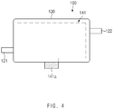
- FIG. 4 is a plan view illustrating a first example in which the electrode and the ground terminal are disposed in the secondary battery according to an embodiment of the present invention
- FIG. 5 is a plan view illustrating a second example in which the electrode and the ground terminal are disposed in the secondary battery according to an embodiment of the present invention.
- FIG. 6 is a plan view illustrating a third example in which the electrode and the ground terminal are disposed in the secondary battery according to an embodiment of the present invention
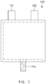
- FIG. 7 is a plan view illustrating a fourth example in which the electrode and the ground terminal are disposed in the secondary battery according to an embodiment of the present invention.
- the ground member 141 may comprise a ground terminal 141a extending in a lateral direction.
- the ground terminal 141a may be disposed in one direction of four lateral directions of the ground member 141 in the plan view of the ground member 141. Also, the ground terminal 141a may be provided in plurality.
- the positive electrode terminal 121 and the negative electrode terminal 122 may be disposed in the same direction of the four lateral directions or in two different directions of the four lateral directions in the plan view of the electrode stack 110.
- the ground terminal 141a may be disposed on one side of a side at which the positive electrode terminal 121 is disposed, a side at which the negative electrode terminal 122 is disposed, and a side at which the positive electrode terminal 121 and the negative electrode terminal 122 are not disposed.
- the ground terminal 141a may be disposed in a direction in which the positive electrode terminal 121 and the negative electrode terminal 122 are disposed or in a direction in which the positive electrode terminal 121 and the negative electrode terminal 122 are not disposed.
- the ground member 141 has a rectangular shape, and the ground terminal 141a may protrude in a width direction of the ground member 141.
- the ground member 141 has a rectangular shape, and the ground terminal 141a may protrude in a longitudinal direction of the ground member 141.
- the ground member 141 has a rectangular shape, and the ground terminal 141a may be provided in plurality in the longitudinal direction of the ground member 141.
- the ground member 141 may have a square shape.
- the ground terminal 141a may be disposed on a side (an opposite side) corresponding to the side at which the positive electrode terminal 121 and the negative electrode terminal 122 are disposed.
- FIG. 8 is a conceptual view illustrating an example of a ground object of a ground line in the secondary battery according to an embodiment of the present invention
- FIG. 9 is a conceptual view illustrating another example of the ground object of the ground line in the secondary battery according to an embodiment of the present invention
- FIG. 10 is a conceptual view illustrating further another example of the ground object of the ground line in the secondary battery according to an embodiment of the present invention.
- the ground line 142 may have one side electrically connected to the ground member 141 and the other side grounded to one or more of a ground G, a storage battery C, and a conductive ground member 20 coming into contact with the ground G to allow the abnormal current introduced into the ground member 141 to flow to the outside through the ground line 142.
- the other side of the ground line 142 may be grounded to the ground G to allow the abnormal current flowing from the ground line 142 to flow to the ground G.
- the storage battery C may store the abnormal current flowing from the ground line 142 therein.
- the storage battery C may be provided as, for example, a capacitor.
- the ground part 140 may comprise a forward diode disposed on the ground line 142 so that current flows only from one side to the other side of the ground line 142.
- the conductive ground member 20 may be made of conductive felt and be disposed in a lower portion of a vehicle 10 to come into contact with the ground G.
- the abnormal current flowing from the ground line 142 through the conductive ground member 20 may flow to the ground G through the other side of the ground line 142.
- the positive electrode 111 and the negative electrode 112 may meet each other to generate sudden abnormal current.
- the abnormal current may flow to the outside of the electrode stack 110 through the ground part 140 to prevent fire such as heat and sparks from occurring.
Landscapes
- Chemical & Material Sciences (AREA)
- Chemical Kinetics & Catalysis (AREA)
- Electrochemistry (AREA)
- General Chemical & Material Sciences (AREA)
- Engineering & Computer Science (AREA)
- Manufacturing & Machinery (AREA)
- Connection Of Batteries Or Terminals (AREA)
- Secondary Cells (AREA)
Abstract
Description
- The present application claims the benefit of the priority of Korean Patent Application No.
10-2016-0096316, filed on July 28, 2016 - The present invention relate to a secondary battery.
- Secondary batteries are rechargeable unlike primarily batteries, and also, the possibility of compact size and high capacity is high. Thus, recently, many studies on secondary batteries are being carried out. As technology development and demands for mobile devices increase, the demands for secondary batteries as energy sources are rapidly increasing.
- Also, secondary batteries are classified into coin type batteries, cylindrical type batteries, prismatic type batteries, and pouch type batteries according to a shape of a battery case. In such a secondary battery, an electrode assembly mounted in a battery case is a chargeable and dischargeable power generating device having a structure in which an electrode and a separator are stacked.
- The electrode assembly may be approximately classified into a jelly-roll type electrode assembly in which a separator is interposed between a positive electrode and a negative electrode, each of which is provided as the form of a sheet coated with an active material, and then, the positive electrode, the separator, and the negative electrode are wound, a stacked type electrode assembly in which a plurality of positive and negative electrodes with a separator therebetween are sequentially stacked, and a stack/folding type electrode assembly in which stacked type unit cells are wound together with a separation film having a long length.
- Typically, there are high demands for pouch-type secondary batteries which are capable of being applied to products such as mobile phones having thin thicknesses in terms of the shapes of the batteries. Also, there are high demands for lithium secondary batteries such as lithium ion batteries and lithium ion polymer batteries, which have high energy densities, high discharge voltages, and excellent output safety in terms of the materials of the batteries.
- In small-sized mobile devices, one or several battery cells per one device are used. However, middle- or large-sized devices such as vehicles require high output large capacity. Thus, a middle- or large-sized battery pack in which a plurality of battery cells as unit cells are electrically connected is used, and also, as an increase in capacitive density is required, cells having higher energy per cell are being developed.
- Since the middle- or large-sized battery pack is necessary to be manufactured so as to have a small size and a light weight, a square shape battery, a pouch shape battery, etc., which may be stacked with high density and light weight when compared with the capacity, are mainly manufactured as the battery cells of the middle- or large-sized battery pack. Among them, the pouch-type battery having a small weight, low possibility of electrolyte leakage, and a low manufacturing cost is particularly attracting much attention.
- The pouch-type battery is influential as the unit cell of the middle- or large-sized battery pack due to its various advantages. However, there is a problem that a pyrotechnic substance such as an electrolyte leaks to increase the risk of fire when a battery case has low mechanical strength, and a sealing part is separated. Also, in case in which an external object such as a nail or the like penetrates through the cell, when a positive electrode and a negative electrode come into direct contact with each other, sudden current flows between the positive electrode and the negative electrode to generate heat, sparks, and the like and thereby to cause outbreak of fire.
- In the middle- or large-sized battery pack in which a plurality of unit cells are electrically connected to each other for the purpose of high-power large-capacity, the above-described firing is a vary serious risk factor that hinders safety.
- One aspect of the present invention is to provide a secondary battery that is capable of improving safety of the battery against an external impact.
- A secondary battery according to an embodiment of the present invention comprises an electrode stack in which an electrode and a separator are combined with each other and a ground part grounding the electrode stack to the outside, wherein the ground part comprises a ground member disposed at one side of the separator to allow abnormal current flowing from the electrode to the one side of the separator to be introduced therein.
- In the secondary battery according to the present invention, when the abnormal current flows due to the external impact, the abnormal current may flow to the outside through the ground part to prevent the heat and the sparks from being generated. Therefore, the safety of the battery against the external impact may be improved.
-
-
FIG. 1 is a perspective view of a secondary battery according to an embodiment of the present invention. -
FIG. 2 is an exploded perspective view illustrating an example in which a ground member is disposed on an electrode stack in the secondary battery according to an embodiment of the present invention. -
FIG. 3 is an exploded perspective view illustrating another example in which the ground member is disposed on the electrode stack in the secondary battery according to an embodiment of the present invention. -
FIG. 4 is a plan view illustrating a first example in which an electrode and a ground terminal are disposed in the secondary battery according to an embodiment of the present invention. -
FIG. 5 is a plan view illustrating a second example in which the electrode and the ground terminal are disposed in the secondary battery according to an embodiment of the present invention. -
FIG. 6 is a plan view illustrating a third example in which the electrode and the ground terminal are disposed in the secondary battery according to an embodiment of the present invention. -
FIG. 7 is a plan view illustrating a fourth example in which the electrode and the ground terminal are disposed in the secondary battery according to an embodiment of the present invention. -
FIG. 8 is a conceptual view illustrating an example of a ground object of a ground line in the secondary battery according to an embodiment of the present invention. -
FIG. 9 is a conceptual view illustrating another example of the ground object of the ground line in the secondary battery according to an embodiment of the present invention. -
FIG. 10 is a conceptual view illustrating further another example of the ground object of the ground line in the secondary battery according to an embodiment of the present invention. - The objectives, specific advantages, and novel features of the present invention will become more apparent from the following detailed description taken in conjunction with the accompanying drawings. It should be noted that the reference numerals are added to the components of the drawings in the present specification with the same numerals as possible, even if they are illustrated in other drawings. Also, the present invention may be embodied in different forms and should not be construed as limited to the embodiments set forth herein. In the following description of the present invention, the detailed descriptions of related arts which may unnecessarily obscure the gist of the present invention will be omitted.
-
FIG. 1 is a perspective view of a secondary battery according to an embodiment of the present invention. - Referring to
FIG. 1 , asecondary battery 100 according to an embodiment of the present invention comprises anelectrode stack 110 and aground part 140 grounding theelectrode stack 110 to the outside. Also, the secondary battery according to an embodiment of the present invention may comprise abattery case 130 accommodating theelectrode stack 110. - Hereinafter, the secondary battery according to an embodiment of the present invention will be described in more detail with reference to
FIGS. 1 to 10 . - Referring to
FIG. 1 , theelectrode stack 110 may be a chargeable and dischargeable power generation element and manufactured by combining anelectrode 113 with aseparator 114. Here, theelectrode stack 110 may be provided with, for example, a jelly-roll type, a stacked-type, or a stack/folding type. - The
separator 114 may be disposed on each of both surfaces of theelectrode 113 or disposed to surround an outer surface of theelectrode 113. - The
electrode 113 comprises apositive electrode 111 and anegative electrode 112. Thus, theelectrode stack 110 may have a structure in which thepositive electrode 111/theseparator 114/thenegative electrode 113 are alternately stacked. Here, theseparator 114 may be disposed between thepositive electrode 111 and thenegative electrode 112 and disposed outside thepositive electrode 111 and outside thenegative electrode 112. Here, theseparator 114 may be disposed to surround theentire electrode stack 110 in which thepositive electrode 111/theseparator 114/thenegative electrode 113 are stacked. - Furthermore, the
separator 114 is made of an insulation material to electrically insulate thepositive electrode 111 from thenegative electrode 112. Here, theseparator 114 may be made of, for example, a polyolefin-based resin film such as polyethylene or polypropylene having micropores. - The
electrode stack 110 may comprises apositive electrode terminal 121 and anegative electrode terminal 122. Here, thepositive electrode terminal 121 may be electrically connected to a side surface of thepositive electrode 111, and thenegative electrode terminal 122 may be electrically connected to a side surface of theelectrode 112. - The
ground part 140 grounds the electrode stack 110 to the outside. Here, theground part 140 may comprise aground member 141 into which abnormal current of theelectrode stack 110 is introduced and aground line 142 grounding theground member 141 to the outside. Thus, the abnormal current introduced into theground member 141 may flow to the outside of thebattery case 130 through theground part 140. - In more detail, the
ground member 141 may be disposed at one side of theseparator 114 so that the abnormal current flowing from theelectrode 113 to one side of theseparator 114 is introduced into theground member 141. - Also, the
ground member 141 may be disposed on the outermost surface of theelectrode stack 110 in a stacking direction of theelectrode stack 110 so that the abnormal current flowing from theelectrode 113 to the outermost surface of theelectrode stack 110 is introduced into theground member 141. Here, theseparator 114 may be disposed on the outermost portion of theelectrode stack 110, and theground member 141 may be disposed on an outer surface of theseparator 114. Here, theground member 141 may be disposed on one or more surfaces of one surface and the other surface of theelectrode stack 110 in the stacking direction of theelectrode stack 110. - Also, the
ground member 141 may be made of a flexible material. Here, theground member 141 may be provided as a foil or thin film. Theground member 141 may have a thickness of 1 um to 2,000 um. - Also, the
ground member 141 may be made of a conductive material. Here, theground member 141 may be made of an aluminum or copper material. - Furthermore, the
ground member 141 may have a plate shape. For example, theground member 141 may have a rectangular plate shape. -
FIG. 2 is an exploded perspective view illustrating an example in which the ground member is disposed on the electrode stack in the secondary battery according to an embodiment of the present invention, andFIG. 3 is an exploded perspective view illustrating another example in which the ground member is disposed on the electrode stack in the secondary battery according to an embodiment of the present invention. - The
electrode stack 110 may be provided in plurality. For example, referring toFIG. 2 , theground member 141 may be disposed between the plurality of electrode stacks 110. For another example, referring toFIG. 3 , theground member 141 may be provided in plurality, and the plurality ofground members 141 may be disposed on both the outermost sides of the plurality of electrode stacks 110. -
FIG. 4 is a plan view illustrating a first example in which the electrode and the ground terminal are disposed in the secondary battery according to an embodiment of the present invention, andFIG. 5 is a plan view illustrating a second example in which the electrode and the ground terminal are disposed in the secondary battery according to an embodiment of the present invention. -
FIG. 6 is a plan view illustrating a third example in which the electrode and the ground terminal are disposed in the secondary battery according to an embodiment of the present invention, andFIG. 7 is a plan view illustrating a fourth example in which the electrode and the ground terminal are disposed in the secondary battery according to an embodiment of the present invention. - Referring to
FIGS. 4 to 7 , theground member 141 may comprise aground terminal 141a extending in a lateral direction. - The
ground terminal 141a may be disposed in one direction of four lateral directions of theground member 141 in the plan view of theground member 141. Also, theground terminal 141a may be provided in plurality. - The
positive electrode terminal 121 and thenegative electrode terminal 122 may be disposed in the same direction of the four lateral directions or in two different directions of the four lateral directions in the plan view of theelectrode stack 110. - Here, when the
positive electrode terminal 121 and thenegative electrode 122 are disposed in the two different directions of the four lateral directions in the plan view of theelectrode stack 110, theground terminal 141a may be disposed on one side of a side at which thepositive electrode terminal 121 is disposed, a side at which thenegative electrode terminal 122 is disposed, and a side at which thepositive electrode terminal 121 and thenegative electrode terminal 122 are not disposed. - Also, when the
positive electrode terminal 121 and thenegative electrode terminal 122 are disposed in the same direction of the four lateral directions in the plan view of theelectrode stack 110, theground terminal 141a may be disposed in a direction in which thepositive electrode terminal 121 and thenegative electrode terminal 122 are disposed or in a direction in which thepositive electrode terminal 121 and thenegative electrode terminal 122 are not disposed. - As a first example, referring to
FIG. 4 , theground member 141 has a rectangular shape, and theground terminal 141a may protrude in a width direction of theground member 141. - Also, as a second example, referring to
FIG. 5 , theground member 141 has a rectangular shape, and theground terminal 141a may protrude in a longitudinal direction of theground member 141. - Furthermore, as a third example, referring to
FIG. 6 , theground member 141 has a rectangular shape, and theground terminal 141a may be provided in plurality in the longitudinal direction of theground member 141. - Also, as a fourth example, referring to
FIG. 7 , theground member 141 may have a square shape. Here, theground terminal 141a may be disposed on a side (an opposite side) corresponding to the side at which thepositive electrode terminal 121 and thenegative electrode terminal 122 are disposed. -
FIG. 8 is a conceptual view illustrating an example of a ground object of a ground line in the secondary battery according to an embodiment of the present invention,FIG. 9 is a conceptual view illustrating another example of the ground object of the ground line in the secondary battery according to an embodiment of the present invention, andFIG. 10 is a conceptual view illustrating further another example of the ground object of the ground line in the secondary battery according to an embodiment of the present invention. - Referring to
FIGS. 8 to 10 , theground line 142 may have one side electrically connected to theground member 141 and the other side grounded to one or more of a ground G, a storage battery C, and aconductive ground member 20 coming into contact with the ground G to allow the abnormal current introduced into theground member 141 to flow to the outside through theground line 142. - Referring to
FIG. 8 , for example, the other side of theground line 142 may be grounded to the ground G to allow the abnormal current flowing from theground line 142 to flow to the ground G. - Referring to
FIG. 9 , for another example, the storage battery C may store the abnormal current flowing from theground line 142 therein. Here, the storage battery C may be provided as, for example, a capacitor. - Here, the
ground part 140 may comprise a forward diode disposed on theground line 142 so that current flows only from one side to the other side of theground line 142. - Referring to
FIG. 10 , for another example, theconductive ground member 20 may be made of conductive felt and be disposed in a lower portion of avehicle 10 to come into contact with the ground G. Thus, the abnormal current flowing from theground line 142 through theconductive ground member 20 may flow to the ground G through the other side of theground line 142. - In the
secondary battery 100 comprising the above-described constituents according to an embodiment of the present invention, when a foreign substance such as a nail penetrates or bursts theelectrode stack 110, thepositive electrode 111 and thenegative electrode 112 may meet each other to generate sudden abnormal current. Here, the abnormal current may flow to the outside of theelectrode stack 110 through theground part 140 to prevent fire such as heat and sparks from occurring. - While the present invention has been particularly shown and described with reference to exemplary embodiments thereof, this is for the purpose of specifically describing the present invention, and thus, the secondary battery according to the present invention is not limited thereto. It will be understood by those of ordinary skill in the art that various changes in form and details may be made therein without departing from the spirit and scope of the invention.
- Furthermore, the scope of protection of the present invention will be clarified by the appended claims.
Claims (20)
- A secondary battery comprising
an electrode stack in which an electrode and a separator are combined with each other; and
a ground part grounding the electrode stack to the outside,
wherein the ground part comprises a ground member disposed at one side of the separator to allow abnormal current flowing from the electrode to the one side of the separator to be introduced therein. - The secondary battery of claim 1, wherein the separator is disposed on each of both surfaces of the electrode.
- The secondary battery of claim 1, wherein the separator surrounds an outer surface of the electrode.
- The secondary battery of any one of claims 1 to 3, wherein the ground member is disposed on one surface of one surface and the other surface of the electrode stack in a stacking direction of the electrode stack.
- The secondary battery of claim 4, wherein the ground member has a plate shape.
- The secondary battery of claim 1, wherein the electrode stack is provided in plurality, and the plurality of electrode stacks are stacked, and
the ground member is disposed between the plurality of electrode stacks. - The secondary battery of claim 1, wherein the electrode stack is provided in plurality, and the plurality of electrode stacks are stacked, and
the ground member is disposed between the plurality of electrode stacks and on each of the outermost electrode stacks. - The secondary battery of claim 1, wherein the ground member has a thickness of 1 um to 2000 um.
- The secondary battery of claim 1, wherein the ground member is made of a conductive material.
- The secondary battery of claim 9, wherein the ground member is made of an aluminum or copper material.
- The secondary battery of claim 1, wherein the ground member is made of a flexible material.
- The secondary battery of claim 1, wherein the ground member further comprises a ground line having one side electrically connected to the ground member to ground the ground member to the outside.
- The secondary battery of claim 12, wherein the ground line has the other side that is grounded to one or more of a ground, a storage battery, and a conductive ground member coming into contact with the ground so that the abnormal current introduced into the ground member flows to the outside.
- The secondary battery of claim 13, wherein the ground part comprises a diode disposed on the ground line so that the current flowing only from the one side to the other side of the ground line.
- The secondary battery of claim 12, wherein the ground member comprises a ground terminal that extends laterally and is connected to the ground line.
- The secondary battery of claim 15, wherein the ground terminal protrudes in one or more directions of four directions in a plan view of the ground member.
- The secondary battery of claim 16, wherein the ground terminal is provided in plurality.
- The secondary battery of claim 15, wherein the electrode comprises a negative electrode and a positive electrode,
a negative electrode terminal is disposed on a side surface of the negative electrode, and a positive electrode terminal is disposed on a side surface of the positive electrode, and
the positive electrode terminal is disposed on one of a side at which the positive electrode terminal is disposed, a side at which the negative electrode terminal is disposed, and a side at which the positive electrode terminal and the negative electrode terminal are not disposed. - The secondary battery of claim 18, wherein the positive electrode terminal and the negative electrode terminal are disposed in the same direction of four directions in a plan view of the electrode stack, and
the ground terminal is disposed in a direction in which the positive electrode terminal and the negative electrode terminal are disposed or a direction in which the positive electrode terminal and the negative electrode terminal are not disposed. - The secondary battery of claim 1, further comprising a battery case accommodating the electrode stack,
wherein the ground part allows the abnormal current introduced into the ground member to flow to the outside of the battery case.
Applications Claiming Priority (2)
| Application Number | Priority Date | Filing Date | Title |
|---|---|---|---|
| KR1020160096316A KR101992430B1 (en) | 2016-07-28 | 2016-07-28 | Rechargeable battery |
| PCT/KR2017/007886 WO2018021765A1 (en) | 2016-07-28 | 2017-07-21 | Secondary battery |
Publications (3)
| Publication Number | Publication Date |
|---|---|
| EP3333940A1 true EP3333940A1 (en) | 2018-06-13 |
| EP3333940A4 EP3333940A4 (en) | 2018-09-19 |
| EP3333940B1 EP3333940B1 (en) | 2023-05-03 |
Family
ID=61016150
Family Applications (1)
| Application Number | Title | Priority Date | Filing Date |
|---|---|---|---|
| EP17834707.6A Active EP3333940B1 (en) | 2016-07-28 | 2017-07-21 | Secondary battery |
Country Status (6)
| Country | Link |
|---|---|
| US (1) | US11335981B2 (en) |
| EP (1) | EP3333940B1 (en) |
| KR (1) | KR101992430B1 (en) |
| CN (1) | CN108140800B (en) |
| PL (1) | PL3333940T3 (en) |
| WO (1) | WO2018021765A1 (en) |
Family Cites Families (11)
| Publication number | Priority date | Publication date | Assignee | Title |
|---|---|---|---|---|
| JP4149349B2 (en) * | 2003-10-15 | 2008-09-10 | Necトーキン株式会社 | Secondary battery and manufacturing method thereof |
| JP5215584B2 (en) | 2007-04-06 | 2013-06-19 | 株式会社Nttファシリティーズ | Separator for lithium ion secondary battery, lithium ion secondary battery using the same, and method for producing lithium ion secondary battery |
| JP5521409B2 (en) | 2008-10-03 | 2014-06-11 | 日産自動車株式会社 | battery |
| KR100919691B1 (en) | 2009-06-24 | 2009-10-06 | 에너테크인터내셔널 주식회사 | Unit cell for secondary battery having conductive sheet layer and lithium ion secondary battery having the same |
| CN102742035B (en) * | 2010-02-03 | 2015-08-19 | 西铁城控股株式会社 | Led drive circuit |
| JP2012028023A (en) | 2010-07-20 | 2012-02-09 | Nissan Motor Co Ltd | Battery |
| KR101528001B1 (en) | 2012-06-22 | 2015-06-10 | 주식회사 엘지화학 | Electrode assembly, manufacture thereof, and secondary batteries including same |
| KR101387617B1 (en) | 2012-09-11 | 2014-04-24 | 주식회사 루트제이드 | Separator for electrode assembly of secondary battery and secondary battery having the same |
| KR101636378B1 (en) | 2013-08-28 | 2016-07-05 | 주식회사 엘지화학 | Module Housing for Unit Module Having Heat Radiation Structure and Battery Module Comprising the Same |
| JP2016103425A (en) | 2014-11-28 | 2016-06-02 | 株式会社デンソー | Zigzag lamination body structure for secondary battery |
| KR101595269B1 (en) * | 2015-12-14 | 2016-02-18 | 홍성우 | Power supply for high-voltage distribution lines |
-
2016
- 2016-07-28 KR KR1020160096316A patent/KR101992430B1/en active IP Right Grant
-
2017
- 2017-07-21 EP EP17834707.6A patent/EP3333940B1/en active Active
- 2017-07-21 US US15/759,032 patent/US11335981B2/en active Active
- 2017-07-21 WO PCT/KR2017/007886 patent/WO2018021765A1/en active Application Filing
- 2017-07-21 CN CN201780003242.8A patent/CN108140800B/en active Active
- 2017-07-21 PL PL17834707.6T patent/PL3333940T3/en unknown
Also Published As
| Publication number | Publication date |
|---|---|
| PL3333940T3 (en) | 2023-09-11 |
| CN108140800B (en) | 2021-08-24 |
| WO2018021765A1 (en) | 2018-02-01 |
| KR20180013123A (en) | 2018-02-07 |
| EP3333940B1 (en) | 2023-05-03 |
| KR101992430B1 (en) | 2019-09-30 |
| US11335981B2 (en) | 2022-05-17 |
| EP3333940A4 (en) | 2018-09-19 |
| US20200161622A1 (en) | 2020-05-21 |
| CN108140800A (en) | 2018-06-08 |
Similar Documents
| Publication | Publication Date | Title |
|---|---|---|
| KR101264527B1 (en) | Pouch case and battery pack using the same | |
| US10056577B2 (en) | Battery cell of novel structure | |
| KR102051109B1 (en) | Battery Module | |
| US10686165B2 (en) | Electrode assembly and secondary battery including the same | |
| KR20140064418A (en) | Secondary battery module | |
| KR101776897B1 (en) | Pouch type secondary battery and method for manufacturing the same | |
| US11362383B2 (en) | Secondary battery | |
| KR20200043402A (en) | Lead tab for battery terminal | |
| KR20180085129A (en) | Battery Cell Comprising Electrode Lead Facing Outer Surface of Electrode Assembly | |
| US11876185B2 (en) | Method for manufacturing secondary battery and secondary battery | |
| KR101749729B1 (en) | Secondary battery | |
| US11128015B2 (en) | Secondary battery | |
| EP3333940B1 (en) | Secondary battery | |
| KR20190051537A (en) | Pouch for rechargeable battery and rechargeable battery comprising the same | |
| KR20200056376A (en) | Secondary Battery Module | |
| KR20190082180A (en) | Secondary Battery Module | |
| KR102158143B1 (en) | Electrode assembly | |
| KR20160054268A (en) | Secondary battery cell and battery module including the same | |
| KR20190005405A (en) | Battery Module | |
| KR20220109781A (en) | Rechargeable battery | |
| KR20220040361A (en) | Rechargeable battery manufacturing method and rechargeable battery | |
| KR20200092672A (en) | Secondary battery and a secondary battery module including the same | |
| JP2023541964A (en) | Secondary battery manufacturing method and secondary battery | |
| KR20190060963A (en) | Secondary battery | |
| KR20130064228A (en) | Secondary battery having electrode lid and electrode tab connected by slit |
Legal Events
| Date | Code | Title | Description |
|---|---|---|---|
| STAA | Information on the status of an ep patent application or granted ep patent |
Free format text: STATUS: THE INTERNATIONAL PUBLICATION HAS BEEN MADE |
|
| PUAI | Public reference made under article 153(3) epc to a published international application that has entered the european phase |
Free format text: ORIGINAL CODE: 0009012 |
|
| STAA | Information on the status of an ep patent application or granted ep patent |
Free format text: STATUS: REQUEST FOR EXAMINATION WAS MADE |
|
| 17P | Request for examination filed |
Effective date: 20180307 |
|
| AK | Designated contracting states |
Kind code of ref document: A1 Designated state(s): AL AT BE BG CH CY CZ DE DK EE ES FI FR GB GR HR HU IE IS IT LI LT LU LV MC MK MT NL NO PL PT RO RS SE SI SK SM TR |
|
| AX | Request for extension of the european patent |
Extension state: BA ME |
|
| A4 | Supplementary search report drawn up and despatched |
Effective date: 20180821 |
|
| RIC1 | Information provided on ipc code assigned before grant |
Ipc: H01M 2/10 20060101AFI20180810BHEP |
|
| DAV | Request for validation of the european patent (deleted) | ||
| DAX | Request for extension of the european patent (deleted) | ||
| RAP1 | Party data changed (applicant data changed or rights of an application transferred) |
Owner name: LG ENERGY SOLUTION LTD. |
|
| RAP3 | Party data changed (applicant data changed or rights of an application transferred) |
Owner name: LG ENERGY SOLUTION, LTD. |
|
| STAA | Information on the status of an ep patent application or granted ep patent |
Free format text: STATUS: EXAMINATION IS IN PROGRESS |
|
| 17Q | First examination report despatched |
Effective date: 20220627 |
|
| REG | Reference to a national code |
Ref country code: DE Ref legal event code: R079 Ref document number: 602017068395 Country of ref document: DE Free format text: PREVIOUS MAIN CLASS: H01M0002340000 Ipc: H01M0010040000 Ref country code: DE Ref legal event code: R079 Free format text: PREVIOUS MAIN CLASS: H01M0002340000 Ipc: H01M0010040000 |
|
| GRAP | Despatch of communication of intention to grant a patent |
Free format text: ORIGINAL CODE: EPIDOSNIGR1 |
|
| STAA | Information on the status of an ep patent application or granted ep patent |
Free format text: STATUS: GRANT OF PATENT IS INTENDED |
|
| RIC1 | Information provided on ipc code assigned before grant |
Ipc: H01M 50/463 20210101ALN20221231BHEP Ipc: H01M 10/052 20100101ALN20221231BHEP Ipc: H01M 50/572 20210101ALI20221231BHEP Ipc: H01M 10/04 19740701AFI20221231BHEP |
|
| RIC1 | Information provided on ipc code assigned before grant |
Ipc: H01M 50/463 20210101ALN20230118BHEP Ipc: H01M 10/052 20100101ALN20230118BHEP Ipc: H01M 50/572 20210101ALI20230118BHEP Ipc: H01M 10/04 20060101AFI20230118BHEP |
|
| INTG | Intention to grant announced |
Effective date: 20230131 |
|
| RIC1 | Information provided on ipc code assigned before grant |
Ipc: H01M 50/463 20210101ALN20230120BHEP Ipc: H01M 10/052 20100101ALN20230120BHEP Ipc: H01M 50/572 20210101ALI20230120BHEP Ipc: H01M 10/04 20060101AFI20230120BHEP |
|
| GRAS | Grant fee paid |
Free format text: ORIGINAL CODE: EPIDOSNIGR3 |
|
| GRAA | (expected) grant |
Free format text: ORIGINAL CODE: 0009210 |
|
| STAA | Information on the status of an ep patent application or granted ep patent |
Free format text: STATUS: THE PATENT HAS BEEN GRANTED |
|
| AK | Designated contracting states |
Kind code of ref document: B1 Designated state(s): AL AT BE BG CH CY CZ DE DK EE ES FI FR GB GR HR HU IE IS IT LI LT LU LV MC MK MT NL NO PL PT RO RS SE SI SK SM TR |
|
| REG | Reference to a national code |
Ref country code: GB Ref legal event code: FG4D |
|
| REG | Reference to a national code |
Ref country code: DE Ref legal event code: R096 Ref document number: 602017068395 Country of ref document: DE |
|
| REG | Reference to a national code |
Ref country code: AT Ref legal event code: REF Ref document number: 1565443 Country of ref document: AT Kind code of ref document: T Effective date: 20230515 Ref country code: CH Ref legal event code: EP |
|
| REG | Reference to a national code |
Ref country code: IE Ref legal event code: FG4D |
|
| REG | Reference to a national code |
Ref country code: SE Ref legal event code: TRGR |
|
| P01 | Opt-out of the competence of the unified patent court (upc) registered |
Effective date: 20230525 |
|
| PGFP | Annual fee paid to national office [announced via postgrant information from national office to epo] |
Ref country code: FR Payment date: 20230621 Year of fee payment: 7 |
|
| REG | Reference to a national code |
Ref country code: LT Ref legal event code: MG9D |
|
| PGFP | Annual fee paid to national office [announced via postgrant information from national office to epo] |
Ref country code: SE Payment date: 20230621 Year of fee payment: 7 |
|
| REG | Reference to a national code |
Ref country code: NL Ref legal event code: MP Effective date: 20230503 |
|
| REG | Reference to a national code |
Ref country code: AT Ref legal event code: MK05 Ref document number: 1565443 Country of ref document: AT Kind code of ref document: T Effective date: 20230503 |
|
| PG25 | Lapsed in a contracting state [announced via postgrant information from national office to epo] |
Ref country code: PT Free format text: LAPSE BECAUSE OF FAILURE TO SUBMIT A TRANSLATION OF THE DESCRIPTION OR TO PAY THE FEE WITHIN THE PRESCRIBED TIME-LIMIT Effective date: 20230904 Ref country code: NO Free format text: LAPSE BECAUSE OF FAILURE TO SUBMIT A TRANSLATION OF THE DESCRIPTION OR TO PAY THE FEE WITHIN THE PRESCRIBED TIME-LIMIT Effective date: 20230803 Ref country code: NL Free format text: LAPSE BECAUSE OF FAILURE TO SUBMIT A TRANSLATION OF THE DESCRIPTION OR TO PAY THE FEE WITHIN THE PRESCRIBED TIME-LIMIT Effective date: 20230503 Ref country code: ES Free format text: LAPSE BECAUSE OF FAILURE TO SUBMIT A TRANSLATION OF THE DESCRIPTION OR TO PAY THE FEE WITHIN THE PRESCRIBED TIME-LIMIT Effective date: 20230503 Ref country code: AT Free format text: LAPSE BECAUSE OF FAILURE TO SUBMIT A TRANSLATION OF THE DESCRIPTION OR TO PAY THE FEE WITHIN THE PRESCRIBED TIME-LIMIT Effective date: 20230503 |
|
| PGFP | Annual fee paid to national office [announced via postgrant information from national office to epo] |
Ref country code: GB Payment date: 20230620 Year of fee payment: 7 |
|
| PG25 | Lapsed in a contracting state [announced via postgrant information from national office to epo] |
Ref country code: RS Free format text: LAPSE BECAUSE OF FAILURE TO SUBMIT A TRANSLATION OF THE DESCRIPTION OR TO PAY THE FEE WITHIN THE PRESCRIBED TIME-LIMIT Effective date: 20230503 Ref country code: LV Free format text: LAPSE BECAUSE OF FAILURE TO SUBMIT A TRANSLATION OF THE DESCRIPTION OR TO PAY THE FEE WITHIN THE PRESCRIBED TIME-LIMIT Effective date: 20230503 Ref country code: LT Free format text: LAPSE BECAUSE OF FAILURE TO SUBMIT A TRANSLATION OF THE DESCRIPTION OR TO PAY THE FEE WITHIN THE PRESCRIBED TIME-LIMIT Effective date: 20230503 Ref country code: IS Free format text: LAPSE BECAUSE OF FAILURE TO SUBMIT A TRANSLATION OF THE DESCRIPTION OR TO PAY THE FEE WITHIN THE PRESCRIBED TIME-LIMIT Effective date: 20230903 Ref country code: HR Free format text: LAPSE BECAUSE OF FAILURE TO SUBMIT A TRANSLATION OF THE DESCRIPTION OR TO PAY THE FEE WITHIN THE PRESCRIBED TIME-LIMIT Effective date: 20230503 Ref country code: GR Free format text: LAPSE BECAUSE OF FAILURE TO SUBMIT A TRANSLATION OF THE DESCRIPTION OR TO PAY THE FEE WITHIN THE PRESCRIBED TIME-LIMIT Effective date: 20230804 |
|
| PGFP | Annual fee paid to national office [announced via postgrant information from national office to epo] |
Ref country code: PL Payment date: 20230628 Year of fee payment: 7 Ref country code: DE Payment date: 20230620 Year of fee payment: 7 |
|
| PG25 | Lapsed in a contracting state [announced via postgrant information from national office to epo] |
Ref country code: FI Free format text: LAPSE BECAUSE OF FAILURE TO SUBMIT A TRANSLATION OF THE DESCRIPTION OR TO PAY THE FEE WITHIN THE PRESCRIBED TIME-LIMIT Effective date: 20230503 |
|
| PG25 | Lapsed in a contracting state [announced via postgrant information from national office to epo] |
Ref country code: SK Free format text: LAPSE BECAUSE OF FAILURE TO SUBMIT A TRANSLATION OF THE DESCRIPTION OR TO PAY THE FEE WITHIN THE PRESCRIBED TIME-LIMIT Effective date: 20230503 |
|
| PG25 | Lapsed in a contracting state [announced via postgrant information from national office to epo] |
Ref country code: SM Free format text: LAPSE BECAUSE OF FAILURE TO SUBMIT A TRANSLATION OF THE DESCRIPTION OR TO PAY THE FEE WITHIN THE PRESCRIBED TIME-LIMIT Effective date: 20230503 Ref country code: SK Free format text: LAPSE BECAUSE OF FAILURE TO SUBMIT A TRANSLATION OF THE DESCRIPTION OR TO PAY THE FEE WITHIN THE PRESCRIBED TIME-LIMIT Effective date: 20230503 Ref country code: RO Free format text: LAPSE BECAUSE OF FAILURE TO SUBMIT A TRANSLATION OF THE DESCRIPTION OR TO PAY THE FEE WITHIN THE PRESCRIBED TIME-LIMIT Effective date: 20230503 Ref country code: EE Free format text: LAPSE BECAUSE OF FAILURE TO SUBMIT A TRANSLATION OF THE DESCRIPTION OR TO PAY THE FEE WITHIN THE PRESCRIBED TIME-LIMIT Effective date: 20230503 Ref country code: DK Free format text: LAPSE BECAUSE OF FAILURE TO SUBMIT A TRANSLATION OF THE DESCRIPTION OR TO PAY THE FEE WITHIN THE PRESCRIBED TIME-LIMIT Effective date: 20230503 Ref country code: CZ Free format text: LAPSE BECAUSE OF FAILURE TO SUBMIT A TRANSLATION OF THE DESCRIPTION OR TO PAY THE FEE WITHIN THE PRESCRIBED TIME-LIMIT Effective date: 20230503 |
|
| REG | Reference to a national code |
Ref country code: DE Ref legal event code: R097 Ref document number: 602017068395 Country of ref document: DE |
|
| PG25 | Lapsed in a contracting state [announced via postgrant information from national office to epo] |
Ref country code: MC Free format text: LAPSE BECAUSE OF FAILURE TO SUBMIT A TRANSLATION OF THE DESCRIPTION OR TO PAY THE FEE WITHIN THE PRESCRIBED TIME-LIMIT Effective date: 20230503 |
|
| PG25 | Lapsed in a contracting state [announced via postgrant information from national office to epo] |
Ref country code: MC Free format text: LAPSE BECAUSE OF FAILURE TO SUBMIT A TRANSLATION OF THE DESCRIPTION OR TO PAY THE FEE WITHIN THE PRESCRIBED TIME-LIMIT Effective date: 20230503 |
|
| REG | Reference to a national code |
Ref country code: CH Ref legal event code: PL |
|
| PLBE | No opposition filed within time limit |
Free format text: ORIGINAL CODE: 0009261 |
|
| STAA | Information on the status of an ep patent application or granted ep patent |
Free format text: STATUS: NO OPPOSITION FILED WITHIN TIME LIMIT |
|
| REG | Reference to a national code |
Ref country code: BE Ref legal event code: MM Effective date: 20230731 |
|
| PG25 | Lapsed in a contracting state [announced via postgrant information from national office to epo] |
Ref country code: LU Free format text: LAPSE BECAUSE OF NON-PAYMENT OF DUE FEES Effective date: 20230721 |
|
| PG25 | Lapsed in a contracting state [announced via postgrant information from national office to epo] |
Ref country code: LU Free format text: LAPSE BECAUSE OF NON-PAYMENT OF DUE FEES Effective date: 20230721 |
|
| 26N | No opposition filed |
Effective date: 20240206 |
|
| REG | Reference to a national code |
Ref country code: IE Ref legal event code: MM4A |
|
| PG25 | Lapsed in a contracting state [announced via postgrant information from national office to epo] |
Ref country code: CH Free format text: LAPSE BECAUSE OF NON-PAYMENT OF DUE FEES Effective date: 20230731 |
|
| PG25 | Lapsed in a contracting state [announced via postgrant information from national office to epo] |
Ref country code: SI Free format text: LAPSE BECAUSE OF FAILURE TO SUBMIT A TRANSLATION OF THE DESCRIPTION OR TO PAY THE FEE WITHIN THE PRESCRIBED TIME-LIMIT Effective date: 20230503 |