EP3333466B1 - Druckluftventil - Google Patents
Druckluftventil Download PDFInfo
- Publication number
- EP3333466B1 EP3333466B1 EP16202872.4A EP16202872A EP3333466B1 EP 3333466 B1 EP3333466 B1 EP 3333466B1 EP 16202872 A EP16202872 A EP 16202872A EP 3333466 B1 EP3333466 B1 EP 3333466B1
- Authority
- EP
- European Patent Office
- Prior art keywords
- piston
- housing
- piston sleeve
- valve
- sleeve
- Prior art date
- Legal status (The legal status is an assumption and is not a legal conclusion. Google has not performed a legal analysis and makes no representation as to the accuracy of the status listed.)
- Active
Links
Images


Classifications
-
- F—MECHANICAL ENGINEERING; LIGHTING; HEATING; WEAPONS; BLASTING
- F16—ENGINEERING ELEMENTS AND UNITS; GENERAL MEASURES FOR PRODUCING AND MAINTAINING EFFECTIVE FUNCTIONING OF MACHINES OR INSTALLATIONS; THERMAL INSULATION IN GENERAL
- F16K—VALVES; TAPS; COCKS; ACTUATING-FLOATS; DEVICES FOR VENTING OR AERATING
- F16K31/00—Actuating devices; Operating means; Releasing devices
- F16K31/12—Actuating devices; Operating means; Releasing devices actuated by fluid
- F16K31/122—Actuating devices; Operating means; Releasing devices actuated by fluid the fluid acting on a piston
- F16K31/1223—Actuating devices; Operating means; Releasing devices actuated by fluid the fluid acting on a piston one side of the piston being acted upon by the circulating fluid
-
- F—MECHANICAL ENGINEERING; LIGHTING; HEATING; WEAPONS; BLASTING
- F16—ENGINEERING ELEMENTS AND UNITS; GENERAL MEASURES FOR PRODUCING AND MAINTAINING EFFECTIVE FUNCTIONING OF MACHINES OR INSTALLATIONS; THERMAL INSULATION IN GENERAL
- F16K—VALVES; TAPS; COCKS; ACTUATING-FLOATS; DEVICES FOR VENTING OR AERATING
- F16K31/00—Actuating devices; Operating means; Releasing devices
- F16K31/12—Actuating devices; Operating means; Releasing devices actuated by fluid
- F16K31/122—Actuating devices; Operating means; Releasing devices actuated by fluid the fluid acting on a piston
-
- B—PERFORMING OPERATIONS; TRANSPORTING
- B33—ADDITIVE MANUFACTURING TECHNOLOGY
- B33Y—ADDITIVE MANUFACTURING, i.e. MANUFACTURING OF THREE-DIMENSIONAL [3D] OBJECTS BY ADDITIVE DEPOSITION, ADDITIVE AGGLOMERATION OR ADDITIVE LAYERING, e.g. BY 3D PRINTING, STEREOLITHOGRAPHY OR SELECTIVE LASER SINTERING
- B33Y80/00—Products made by additive manufacturing
-
- F—MECHANICAL ENGINEERING; LIGHTING; HEATING; WEAPONS; BLASTING
- F16—ENGINEERING ELEMENTS AND UNITS; GENERAL MEASURES FOR PRODUCING AND MAINTAINING EFFECTIVE FUNCTIONING OF MACHINES OR INSTALLATIONS; THERMAL INSULATION IN GENERAL
- F16K—VALVES; TAPS; COCKS; ACTUATING-FLOATS; DEVICES FOR VENTING OR AERATING
- F16K1/00—Lift valves or globe valves, i.e. cut-off apparatus with closure members having at least a component of their opening and closing motion perpendicular to the closing faces
- F16K1/12—Lift valves or globe valves, i.e. cut-off apparatus with closure members having at least a component of their opening and closing motion perpendicular to the closing faces with streamlined valve member around which the fluid flows when the valve is opened
- F16K1/126—Lift valves or globe valves, i.e. cut-off apparatus with closure members having at least a component of their opening and closing motion perpendicular to the closing faces with streamlined valve member around which the fluid flows when the valve is opened actuated by fluid
-
- F—MECHANICAL ENGINEERING; LIGHTING; HEATING; WEAPONS; BLASTING
- F16—ENGINEERING ELEMENTS AND UNITS; GENERAL MEASURES FOR PRODUCING AND MAINTAINING EFFECTIVE FUNCTIONING OF MACHINES OR INSTALLATIONS; THERMAL INSULATION IN GENERAL
- F16K—VALVES; TAPS; COCKS; ACTUATING-FLOATS; DEVICES FOR VENTING OR AERATING
- F16K27/00—Construction of housing; Use of materials therefor
- F16K27/04—Construction of housing; Use of materials therefor of sliding valves
- F16K27/041—Construction of housing; Use of materials therefor of sliding valves cylindrical slide valves
-
- F—MECHANICAL ENGINEERING; LIGHTING; HEATING; WEAPONS; BLASTING
- F16—ENGINEERING ELEMENTS AND UNITS; GENERAL MEASURES FOR PRODUCING AND MAINTAINING EFFECTIVE FUNCTIONING OF MACHINES OR INSTALLATIONS; THERMAL INSULATION IN GENERAL
- F16K—VALVES; TAPS; COCKS; ACTUATING-FLOATS; DEVICES FOR VENTING OR AERATING
- F16K3/00—Gate valves or sliding valves, i.e. cut-off apparatus with closing members having a sliding movement along the seat for opening and closing
- F16K3/22—Gate valves or sliding valves, i.e. cut-off apparatus with closing members having a sliding movement along the seat for opening and closing with sealing faces shaped as surfaces of solids of revolution
- F16K3/24—Gate valves or sliding valves, i.e. cut-off apparatus with closing members having a sliding movement along the seat for opening and closing with sealing faces shaped as surfaces of solids of revolution with cylindrical valve members
- F16K3/26—Gate valves or sliding valves, i.e. cut-off apparatus with closing members having a sliding movement along the seat for opening and closing with sealing faces shaped as surfaces of solids of revolution with cylindrical valve members with fluid passages in the valve member
- F16K3/265—Gate valves or sliding valves, i.e. cut-off apparatus with closing members having a sliding movement along the seat for opening and closing with sealing faces shaped as surfaces of solids of revolution with cylindrical valve members with fluid passages in the valve member with a sleeve sliding in the direction of the flow line
Definitions
- the present invention relates generally to valves and in particular to valves comprising a piston member that moves between a valve open position and a valve closed position.
- Axial type pneumatic valves are commonly used in aerospace applications, for example, in engine/nacelle anti-icing systems, engine bleed control, etc.
- Such valves comprise an external housing that houses a number of internal parts, including a piston, poppet, seals and springs etc.
- the housing is formed from multiple component parts that are conventionally formed by casting or from machined stock. The component parts are then joined together during the assembly process, e.g. using bolts or by welding, and the internal parts are incorporated in the housing.
- US 2016/200442 A1 discloses an axial type pneumatic valve according to the preamble of claim 1.
- FR 3 018 892 A1 discloses another known axial type pneumatic valve.
- the present invention provide a pneumatic valve as claimed in claim 1.
- the housing may be a monobloc housing.
- the continuous single-piece of material may surround the whole of the piston sleeve and the piston.
- the continuous single-piece of material may form substantially the entirety of the exterior surfaces of the valve.
- the housing may be formed by an additive manufacturing or 3D printing technique.
- the housing may be formed by Direct Laser Metal Sintering or Electron Beam Metal Sintering.
- the housing may be formed by other techniques, such as casting.
- the valve may be an axial type valve, wherein the axes through the inlet and outlet ports are parallel and/or coaxial.
- the piston is slidably mounted in the piston sleeve so as to be movable to an open position in which the inlet port and outlet port are in fluid communication, and a closed position in which the piston blocks fluid communication between the inlet and outlet ports.
- the piston may be a tubular member having a conduit therein that is in fluid communication with the outlet port, and one or more apertures in a circumferential wall of the piston for allowing fluid communication with the inlet port when the piston is in the open position.
- the one or more apertures in the wall of the piston are located such that fluid communication between the inlet and exit ports is blocked.
- the piston sleeve may have one or more apertures through its circumferential wall for allowing fluid communication between the inlet and outlet ports, via the one or more apertures in the piston, when the piston is arranged in the open position.
- the one or more apertures in the piston sleeve are not aligned with one or more apertures in the piston, thereby blocking fluid flow between the inlet and outlet ports.
- the housing may define a piston chamber and the piston sleeve may be mounted against, or to, the internal surface of the housing in the piston chamber.
- the piston sleeve may be a substantially tubular member, such as a substantially cylindrical member.
- the piston sleeve may be rigid.
- the inner surface of the piston sleeve may be a friction reducing coating or layer, or the inner surface of the piston sleeve may be a lower friction material than the housing material. Alternatively, or additionally, the inner surface of the piston sleeve may be a harder material than the housing material.
- the piston may comprise a seal at each end thereof that contacts the inner surface of the piston sleeve to form a seal between the piston and sleeve that is maintained as the piston is moved within the piston sleeve.
- the piston sleeve may be formed from first and second tubular portions that interconnect by having overlapping end portions, wherein the interconnecting end of the second tubular portion is recessed along a length thereof on its radially inner side, and wherein the recessed length only partially overlaps the first tubular portion so that the remainder of the recessed length forms said detent.
- the interconnecting end of the first tubular portion may be recessed along a length thereof on its radially outer side, wherein this recessed length overlaps the recessed length of the second tubular member.
- the piston sleeve and/or first tubular member and/or second tubular member and/or piston may be sized and configured so as to be axially insertable into the housing through the exit port.
- An inner surface of the housing may be configured to prevent axial movement of the piston sleeve in a first direction and/or the valve may comprise one or more securing member for preventing axial movement of the piston sleeve relative to the housing in a second opposite direction and out of the exit port.
- the securing member may be a ferrule or other member that is attachable to the housing to prevent the sleeve moving out of the exit port.
- the one or more securing member may be engagable and disengagable with the housing, e.g. repeatedly engagable and disengagable with the housing. This allows the piston and/or piston sleeve to be removed from the housing, e.g. to replace or repair these elements.
- the piston sleeve may engage the housing and/or securing member with one or more mating profiles that are configured so that the one or more mating profiles ensure fluid tightness between the piston sleeve and the housing and/or securing member so as to prevent fluids, such as gases, from passing around the outside of the piston sleeve.
- the housing formed from the continuous single-piece of material may further comprise one or more conduits through a wall thereof for connecting the inlet and/or outlet port to pressure control devices and/or to other pressure fittings. Accordingly, in addition to the main valve conduit extending between the inlet and outlet ports, the housing further defines at least one further port and at least one further conduit extending between the at least one further port and the main conduit.
- the at least one further conduit may be used to convey pressure from the inlet port and/or outlet port to a pressure control device that controls the position of the piston.
- the pressure control device may comprise, for example, a solenoid valve or a pressure regulating valve etc.
- Embodiments also provide a method of manufacturing the valve described herein, comprising:
- the step of forming said housing may comprise forming said housing using an additive manufacturing or 3D printing technique.
- the housing may be formed by Direct Laser Metal Sintering or Electron Beam Metal Sintering.
- the housing may be formed by other techniques, such as casting.
- Step b) of the above method may comprise inserting one end of the piston into a first portion of the piston sleeve and another end of the piston into a second portion of the piston sleeve, and step c) may comprise inserting the combination of the piston and both portions of said piston sleeve together into the housing through the exit port.
- steps e) and f) of the above method may comprise: inserting a first portion of the piston sleeve into the housing through the exit port; inserting the piston through the exit port and into the first portion of the piston sleeve; and inserting a second portion of the piston sleeve into the housing through the exit port so as to surround the piston.
- the method may comprise connecting one or more securing member to the housing to prevent axial movement of the piston sleeve relative to the housing.
- the piston sleeve may engage the housing and/or securing member with one or more mating profiles that are configured so that the one or more mating profiles ensure fluid tightness between the piston sleeve and the housing and/or securing member so as to prevent fluids, such as gases, from passing around the outside of the piston sleeve.
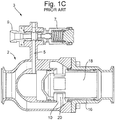
- Fig. 1A shows a perspective view of a valve according to the prior art.
- Figs. 1B and 1C show cross-sectional views of the valve in a closed position and an open position, respectively.
- the valve comprises a housing 2 formed from a first portion 2a and a second portion 2b that are secured together.
- the housing 2 defines an inlet port 4, an annular fluid inlet conduit 6, a piston chamber 8, an annular fluid entrance 10 into the piston chamber 8, a valve control chamber 28, a control turret 3, and an exit port 14.
- a longitudinally extended, tubular piston 16 having an axial conduit 18 therethrough is arranged in the piston chamber 8.
- the piston 16 has apertures 20 in its circumferential wall that allow fluid communication between the outside of the piston 16 and the conduit 18 therein.
- the piston 16 also comprises a radial projection 22 extending outwardly from the circumferential surface and located on a downstream side of the apertures 20.
- the piston 16 is arranged in the piston chamber 8 so as to be movable along an axis that is coaxial with the axis through the inlet and exit ports 4,14.
- a first piston seal 24 is arranged on a first end of the piston 16, upstream of the apertures 20, so as to provide a fluid seal between the first end of the piston 16 and housing 2.
- a second piston seal 26 is arranged on a second end of the piston 16, downstream of the radial projection 22, so as to provide a fluid seal between the second end of the piston and the housing 2.
- the housing 2 and the head of the piston 16 define the valve control chamber 28, which can be used in controlling the axial position of the piston 16.
- the control turret 3 comprises a control conduit 5 for fluidly connecting one or more control devices to the chamber 28.
- the control device(s) may then be used to vary the pressure of the fluid in the control chamber 28, so as to change the position of the piston 16.
- the control turret 3 comprises a control device in the form of a pressure limiting valve 7 connected to the control conduit 5, and a fitting 9 for connecting another of said control devices to the control conduit 5.
- the control device may, for example, comprise a solenoid valve, a pressure regulating valve etc. Each control device may form part of the valve 2 or may be connectable thereto.
- the valve 2 may be moved between the closed position shown in Fig. 1B and the open position shown in Fig. 1C depending on the pressure differential across the piston head, i.e. the pressure differential between the valve control chamber 28 and the conduit 18 of the piston 16. If the pressure differential is such that the pressure in the valve control chamber 28 is lower than the pressure inside the piston 16, then the piston 16 moves to the closed position shown in Fig. 1B . However, if the pressure differential is such that the pressure in the valve control chamber 28 is higher than the pressure inside the piston 16, then the piston 16 moves to the open position shown in Fig. 1C . These events may occur by selectively decreasing or increasing the pressure in the valve control chamber 28, i.e. by releasing or injecting a fluid into the valve control chamber 28 through control conduit 5.
- first end of the piston 16 is inserted into the first portion 2a of the housing 2 and the second portion of the housing 2b is then arranged over the second end of the piston 16.
- the first and second portions of the housing 2a,2b are then secured together, e.g. by bolts 30.
- valve imposes constraints on the geometries of the housing components, which in turn limits the configuration and performance the valve.
- the internal surface of the housing 2 acts as a cylinder in which the piston moves and so requires sophisticated and accurate surface finishing processes that are often not suitable to the housing geometry. Consequently, compromises must be made in the design and manufacturing of such valves so as to accommodate the various requirements, which may lead to non-optimised performance of the valves and complex manufacturing methods.
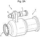
- Fig. 2A shows a perspective view of a valve according an embodiment of the present invention.
- Fig. 2B shows a cross-sectional view of the valve of Fig. 2A , when in a closed position.
- the valve is similar to that shown and described in Figs. 1A-1C , except that the housing 2 is formed from a single piece of continuous material that surrounds the piston 16 (rather than first and second housing portions that are secured together around the piston), and a piston sleeve 32 is arranged between the housing 2 and the piston 16.
- the housing 2 may be formed by an additive manufacturing or 3D printing technique such as Direct Laser Metal Sintering or Electron Beam Metal Sintering.
- housing 2 can be made with maximum performance-weight-cost-geometry and in a relatively simple manner.
- housing could be manufactured by other techniques, such as casting. The construction and operation of the embodiment will be described in more detail below.
- the valve comprises an external housing 2 formed from a single piece of material (e.g. a monobloc housing).
- the housing 2 defines an inlet port 4, an annular fluid inlet conduit 6, a piston chamber 8, an annular fluid entrance 10 into the piston chamber 8, a valve control chamber 28, a control turret 3, and an exit port 14.
- a longitudinally extended, tubular piston 16 having an axial conduit 18 therethrough is arranged in the piston chamber 8.
- a cylindrical piston sleeve 32 is arranged around the piston 16 so as to slidably mount the piston 16 to the housing 2.
- the piston sleeve 32 has apertures 34 in its circumferential wall that allow fluid to pass through the piston sleeve 32.
- the piston 16 has apertures 20 in its circumferential wall that allow fluid communication between the outside of the piston 16 and the conduit 18 therein.
- the piston 16 also has one or more radial projections 22 extending outwardly from the circumferential surface and located on a downstream side of the apertures 20.
- the one or more radial projections 22 extend outwardly to interact with the piston sleeve 32, as will be described in more detail below.
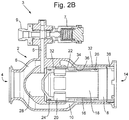
- Figs. 3A and 3B show perspective and cross-sectional views of the piston sleeve 32, respectively.
- the piston sleeve 32 is formed from a first tubular portion 32a and a second tubular portion 32b having the apertures 34 therethrough and that connects with the first tubular portion 32a to form the piston sleeve 32.
- the first tubular portion 32a has a first end region having a relatively thick wall and a second end region that is recessed on the outer surface such that the wall in the second end region is thinner.
- the second tubular portion 32b also has a first end region having a relatively thick wall and a second end region that is recessed on the inner surface such that the wall in the second end region is thinner.
- the recessed second end region of the second tubular portion 32b includes the apertures 34.
- the tubular portions 32a,32b are sized and configured such that the recessed second end portion of the second tubular portion 32b can be partially slid over the recessed second end portion of the first tubular 32a, e.g. to create a tight fit, precision fit, or less desirably an interference fit.
- the resulting piston sleeve 32 has a circumferential detent 36 on the inner surface of the piston sleeve 32, with a first end of the detent defined by the second end of the first tubular portion 32a and a second end of the detent 36 defined by the transition between the recessed and non-recessed portion of the second tubular portion 32b.
- the one or more radial projections 22 on the piston 16 extend outwardly into the detent 36 in the piston sleeve 32, such that movement of the piston 16 within the piston sleeve 32 is limited, as described in more detail below.
- the piston 16 is arranged in the piston sleeve 32 so as to be movable along an axis that is coaxial with the axis through the inlet and exit ports 4,14.
- a first piston seal 24 is arranged on a first end of the piston 16, upstream of the apertures 20, so as to provide a fluid seal between the first end of the piston 16 and piston sleeve 32.
- a second piston seal 26 is arranged on a second end of the piston 16, downstream of the radial projection 22, so as to provide a fluid seal between the second end of the piston 16 and the piston sleeve 32.
- the housing 2 and the head of the piston 16 define the valve control chamber 28, which can be used in controlling the axial position of the piston 16.
- the control turret 3 comprises a control conduit 5 for fluidly connecting one or more control devices to the chamber 28.
- the control device(s) may then be used to vary the pressure of the fluid in the control chamber 28, so as to change the position of the piston 16.
- the control turret 3 comprises a control device in the form of a pressure limiting valve 7 connected to the control conduit 5, and a fitting 9 for connecting another of said control devices to the control conduit 5.
- the control device may, for example, comprise a solenoid valve, a pressure regulating valve etc. Each control device may form part of the valve or may be connectable thereto.
- the valve may be moved between the closed position shown in Fig. 2B and an open position (not shown) depending on the pressure differential across the piston head, i.e. the pressure differential between the valve control chamber 28 and the conduit 18 of the piston 16. If the pressure differential is such that the pressure in the valve control chamber 28 is lower than the pressure inside the piston 16, then the piston 16 moves to the closed position shown in Fig. 2B . However, if the pressure differential is such that the pressure in the valve control chamber 28 is higher than the pressure inside the piston 16, then the piston 16 moves to the open position. These events may occur by selectively decreasing or increasing the pressure in the valve control chamber 28, i.e. by releasing or injecting a fluid into the valve control chamber 28 through control conduit 5.
- the solid portion of the piston 16 is aligned with the apertures 34 in the piston sleeve 32 and the annular fluid entrance 10. Also, as the at least one radial projection 22 abuts against the upstream edge of the detent 36 in the piston sleeve 32, fluid is prevented from passing in the upstream direction between the piston 16 and the piston sleeve 32.
- the piston seal 26 on the downstream end of the piston 16 prevents the fluid from passing downstream of the piston 16 between the piston 16 and the piston sleeve 32. As such, the fluid is prevented from passing between the inlet port 4 and the outlet port 14 and so is prevented from exiting the valve.
- the first tubular portion 32a of the piston sleeve 32 is inserted through the outlet port 14 of the housing 2 into the piston chamber 8, with the recessed end of the first tubular portion 32a directed towards the outlet port 14.
- the piston 16 is then inserted through the outlet port 14 of the housing 2 such that the piston head enters the first tubular portion 32a of the piston sleeve 32.
- the seal 24 on the piston head engages the inner surface of the first tubular portion 32a and the piston 16 is continued to be urged into the first tubular portion 32a of the piston sleeve 32 until the one or more radial projection 22 on the piston 16 abuts the second end of the first tubular portion 32a of the piston sleeve 32.
- the second tubular portion 32b of the piston sleeve 32 is then inserted through the outlet port 14 of the housing 2, with the recessed second end portion being inserted first.
- the recessed portion of the second tubular portion 32b slides over the recessed portion of the first tubular portion 32a until the end of the second tubular portion 32b abuts against the shoulder that forms the transition between the thick portion and the recessed portion of the first tubular portion 32a.
- the resulting piston sleeve 32 has the circumferential detent 36 on the inner surface of the piston sleeve 32.
- a retaining ferrule 38 is then inserted into the outlet port 14 behind the second tubular portion 32b of the sleeve 32 so as to retain the piston sleeve 32 in the housing 2.
- the ferrule 38 and housing 2 may have cooperating screw threads such that the ferrule 38 may be screwed in place into the housing 2.
- the tightness of the piston sleeve 32 to the housing 2 that is required may be achieved by suitable profiles at the two ends of the sleeve 32, and mating profiles in the housing 2.
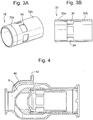
- Fig. 4 shows a schematic view of another embodiment that is the same as that shown in Figs. 2A-2B , except that the monobloc housing 2 has a further channel 40 therethrough (and the control turret 3 is not shown).
- This channel 40 leads from the conduit 6, through the wall of the housing 2, to a second outlet 42.
- This channel 40 may be used, for example, to supply pressure at the inlet port 4 to the one or more control devices attached to the control tower 3.
- This pressure feedback may be used by the one or more control devices to control the pressure in chamber 28 and hence the position of the piston.
- the provision of a channel 40 through the monobloc housing 2 enables external pipework to be eliminated, thus leading to lower parts count, lower weight, a smaller envelope, and increased reliability.
- a corresponding channel may extend through the wall of the housing 2 to supply pressure at the outlet port 14 to the one or more control devices attached to the control tower 3. This pressure feedback may be used by the one or more control devices to control the pressure in chamber 28 and hence the position of the piston.
- a housing 2 and an independent piston sleeve 32 enables the geometry of the housing 2 to be optimized for its function (dictated by fluid dynamics) and for mechanical strength, since it is not required to provide the function of the piston sleeve 32.
- the internal surface of the housing 2 i.e. the surface of the piston cavity
- the independent piston sleeve 32 is able to me made with the tolerances required and from a different material to the housing 2 that is more suitable for the function as a piston sleeve 32 (e.g. high hardness, low friction, etc.).
- the independent sleeve 32 will allow very accurate machining and, if required, accurate coating on its internal surface with limited costs. Also the servicing/overhauling costs of the valve will be reduced, since the piston 16 and/or piston sleeve 32 may be replaced without replacing the housing 2 (the housing not being a wear-part in the embodiments of the invention, unlike the prior art).
- valve described herein may be a valve for aerospace applications, for example, for engine/nacelle anti-icing systems, engine bleed control, etc.
- the geometry of the housing may be optimized for its intended function and mechanical strength, whilst still providing the piston with a suitable piston receiving surface.
- the internal surface of the housing need not be made to the high tolerances and have the special surface coatings required in conventional housings that act as the piston sleeve/cylinder, because in various embodiments the housing need not act as the piston cylinder.
- the independent piston sleeve of the various embodiments may be made from a different material to the housing and is able to be provided with the required tolerances, so that the sleeve has the desired properties.
- the sleeve may be formed independently from the housing, it may have a simple geometry and is readily accessible prior to installation in the housing. As such, the piston sleeve may be accurately machined and, if required, may be accurately coated on its internal piston-receiving surface prior to installation in the housing.
- valve may be a normally open valve, a normally closed valve, a regulating valve, a shut-off valve, single piston valve, a dual piston valve, etc.
- the specific type of valve is not essential. Rather, an important aspect is that the valve housing is formed from a continuous single-piece of material and that one or more independent piston sleeve is provided for one or more respective pistons.
Landscapes
- Engineering & Computer Science (AREA)
- General Engineering & Computer Science (AREA)
- Mechanical Engineering (AREA)
- Physics & Mathematics (AREA)
- Fluid Mechanics (AREA)
- Chemical & Material Sciences (AREA)
- Manufacturing & Machinery (AREA)
- Materials Engineering (AREA)
- Fluid-Driven Valves (AREA)
Claims (13)
- Druckluftventil, umfassend:ein Außengehäuse (2), das einen Fluideinlassanschluss (4) und einen Fluidauslassanschluss (14) definiert;eine Kolbenhülse (32); undeinen Kolben (16), der verschiebbar innerhalb der Kolbenhülse (32) montiert ist,wobei die Kolbenhülse (32) und der Kolben (16) geometrisch konfiguriert sind, um so zusammenzuwirken, dass sie die verschiebbare Bewegung des Kolbens (16) innerhalb der Kolbenhülse (32) zwischen einer offenen Position und einer geschlossenen Position beschränken,wobeientweder die Kolbenhülse (32) eine radiale Raste (36) umfasst, die sich entlang der Kolbenhülse erstreckt, und der Kolben (16) einen radialen Vorsprung (22) umfasst, der in der Raste (36) aufgenommen wird, oder der Kolben (16) eine radiale Raste umfasst, die sich entlang des Kolbens erstreckt, und die Kolbenhülse (32) einen Vorsprung umfasst, der in der Raste aufgenommen wird, um so die verschiebbare Bewegung des Kolbens (16) innerhalb der Kolbenhülse (32) in einer ersten und einer zweiten Richtung zu beschränken,dadurch gekennzeichnet, dassdas Außengehäuse (2) aus einem durchgängigen einzigen Materialstück hergestellt ist und darin, dass die Kolbenhülse (32) eine gesonderte Kolbenhülse (32) ist, die innerhalb des Außengehäuses (2) aufgenommen ist.
- Ventil nach Anspruch 1, wobei das Gehäuse (2) durch ein Verfahren der additiven Fertigung oder des 3D-Druckens hergestellt wird.
- Ventil nach Anspruch 1 oder 2, wobei die Innenfläche der Kolbenhülse (32) eine reibungsmindernde Beschichtung oder Schicht ist oder die Innenfläche der Kolbenhülse (32) ein Material mit geringerer Reibung als das Gehäusematerial ist; und/oder
wobei die Innenfläche der Kolbenhülse (32) ein härteres Material als das Gehäusematerial ist. - Ventil nach einem der vorstehenden Ansprüche, wobei in Anordnungen, in denen die Kolbenhülse (32) die radiale Raste (36), die sich entlang der Kolbenhülse erstreckt, umfasst und der Kolben (16) den radialen Vorsprung (22), der in der Raste (36) aufgenommen wird, umfasst, die Kolbenhülse (32) aus einem ersten und einem zweiten röhrenförmigen Abschnitt (32a, 32b) gebildet ist, die dadurch miteinander verbunden werden, dass sie überlappende Endabschnitte aufweisen, wobei das Verbindungsende des zweiten röhrenförmigen Abschnitts (32b) entlang einer Länge davon auf seiner radial inneren Seite vertieft ist, und wobei die vertiefte Länge nur zum Teil den ersten röhrenförmigen Abschnitt (32a) überlappt, so dass der Rest der vertieften Länge die Raste (36) bildet.
- Ventil nach einem der vorstehenden Ansprüche, wobei die Kolbenhülse (32) und/oder der erste röhrenförmige Abschnitt (32a) und/oder der zweite röhrenförmige Abschnitt (32b) und/oder der Kolben (16) so bemessen und konfiguriert ist/sind, dass sie/er axial in das Gehäuse durch den Auslassanschluss (14) eingesetzt werden kann/können.
- Ventil nach Anspruch 5, wobei eine Innenfläche des Gehäuses (2) konfiguriert ist, um eine axiale Bewegung der Kolbenhülse (32) in einer ersten Richtung zu verhindern, und/oder das Ventil ein oder mehrere Sicherungselement(e) (38) umfasst, um die axiale Bewegung der Kolbenhülse (32) in Bezug auf das Gehäuse (2) in einer zweiten entgegengesetzten Richtung und aus dem Auslassanschluss (14) heraus zu verhindern.
- Ventil nach einem der vorstehenden Ansprüche, wobei die Kolbenhülse (32) in das Gehäuse (2) eingreift und/oder, wenn Anspruch 7 von Anspruch 6 abhängt, in das eine oder die mehreren Sicherheitselement(e) (38) mit einem oder mehreren passenden Profil(en), das/die so konfiguriert ist/sind, dass das eine oder die mehreren passende(n) Profil(e) eine Fluiddichtigkeit zwischen der Kolbenhülse und dem Gehäuse und/oder dem einen oder den mehreren Sicherheitselement(en) sicherstellt/sicherstellen, um so zu verhindern, dass Fluide, wie etwa Gase, um das Äußere der Kolbenhülse (32) herumströmen.
- Ventil nach einem der vorstehenden Ansprüche, wobei das Gehäuse, das aus dem durchgängigen einzelnen Materialstück hergestellt ist, ferner eine oder mehrere Leitung(en) (40) durch eine Wand davon umfasst, um den Einlass- und/oder den Auslassanschluss (4, 14) mit Druckregelungsvorrichtung und/oder mit anderen Druckarmaturen zu verbinden.
- Verfahren zum Herstellen des Ventils nach einem der vorstehenden Ansprüche, umfassend:a) Herstellen oder Bereitstellen des Gehäuses (2);b) Einsetzen des Kolbens (16) in mindestens einen Abschnitt der Kolbenhülse (32); und dannc) Einsetzen der Kombination aus dem Kolben (16) und mindestens einem Abschnitt der Kolbenhülse (32) zusammen in das Gehäuse durch den Auslassanschluss (14); oderd) Herstellen oder Bereitstellen des Gehäuses (2); e) Einsetzen mindestens eines Abschnitts der Kolbenhülse (32) in das Gehäuse (2) durch den Auslassanschluss (14); und dann f) Einsetzen des Kolbens (16) durch den Auslassanschluss (14) und in die Kolbenhülse (32).
- Verfahren nach Anspruch 9, wobei der Schritt des Herstellens des Gehäuses (2) das Herstellen des Gehäuses unter Verwendung eines Verfahrens der additiven Fertigung oder des 3D-Druckens umfasst.
- Verfahren nach Anspruch 9 oder 10,
wobei Schritt b) das Einsetzen eines Endes des Kolbens (16) in einen ersten Abschnitt der Kolbenhülse (32a) und eines anderen Endes des Kolbens (16) in einen zweiten Abschnitt der Kolbenhülse (32b) umfasst und Schritt c) das Einsetzen der Kombination aus dem Kolben und beiden Abschnitten der Kolbenhülse (32a, 32b) zusammen in das Gehäuse durch den Auslassanschluss (14) umfasst; oder
wobei die Schritte e) und f) Folgendes umfassen: Einsetzen eines ersten Abschnitts der Kolbenhülse (32) in das Gehäuse (2) durch den Auslassanschluss (14); Einsetzen des Kolbens (16) durch den Auslassanschluss (14) und in den ersten Abschnitt der Kolbenhülse (32a); und Einsetzen eines zweiten Abschnitts der Kolbenhülse (32b) in das Gehäuse durch den Auslassanschluss (14), so dass sie den Kolben (16) umgibt. - Verfahren nach einem der Ansprüche 9 - 11, umfassend das Verbinden eines oder mehrerer Sicherungselemente(s) (38) mit dem Gehäuse (2), um eine axiale Bewegung der Kolbenhülse (32) in Bezug auf das Gehäuse zu verhindern.
- Verfahren nach einem der Ansprüche 9 - 12, wobei die Kolbenhülse (32) in das Gehäuse (2) eingreift und/oder, wenn Anspruch 13 von Anspruch 12 abhängt, in das eine oder die mehreren Sicherheitselement(e) (38) mit einem oder mehreren passenden Profil(en), das/die so konfiguriert ist/sind, dass das eine oder die mehreren passende(n) Profil(e) eine Fluiddichtigkeit zwischen der Kolbenhülse und dem Gehäuse (2) und/oder dem einen oder den mehreren Sicherheitselement(en) (38) sicherstellt/sicherstellen, um so zu verhindern, dass Fluide, wie etwa Gase, um das Äußere der Kolbenhülse (32) herumströmen.
Priority Applications (2)
| Application Number | Priority Date | Filing Date | Title |
|---|---|---|---|
| EP16202872.4A EP3333466B1 (de) | 2016-12-08 | 2016-12-08 | Druckluftventil |
| US15/834,334 US10823306B2 (en) | 2016-12-08 | 2017-12-07 | Pneumatic valve |
Applications Claiming Priority (1)
| Application Number | Priority Date | Filing Date | Title |
|---|---|---|---|
| EP16202872.4A EP3333466B1 (de) | 2016-12-08 | 2016-12-08 | Druckluftventil |
Publications (2)
| Publication Number | Publication Date |
|---|---|
| EP3333466A1 EP3333466A1 (de) | 2018-06-13 |
| EP3333466B1 true EP3333466B1 (de) | 2019-09-25 |
Family
ID=57569885
Family Applications (1)
| Application Number | Title | Priority Date | Filing Date |
|---|---|---|---|
| EP16202872.4A Active EP3333466B1 (de) | 2016-12-08 | 2016-12-08 | Druckluftventil |
Country Status (2)
| Country | Link |
|---|---|
| US (1) | US10823306B2 (de) |
| EP (1) | EP3333466B1 (de) |
Families Citing this family (9)
| Publication number | Priority date | Publication date | Assignee | Title |
|---|---|---|---|---|
| EP3587876B1 (de) * | 2018-06-22 | 2022-03-02 | Microtecnica S.r.l. | Druckregelabsperrventil, kolben dafür und zugehörige herstellungsverfahren |
| FR3083288B1 (fr) * | 2018-06-29 | 2021-01-22 | Safran Aircraft Engines | Vanne de decharge a piston a conduit interne |
| US10865715B2 (en) | 2018-12-07 | 2020-12-15 | Raytheon Technologies Corporation | Passive stability bleed valve with adjustable reference pressure regulator and remote override capability |
| RU194819U1 (ru) * | 2019-08-30 | 2019-12-24 | Акционерное общество "Концерн "Научно-производственное объединение "Аврора" | Пневматический клапан для импульсных установок |
| WO2023069361A1 (en) * | 2021-10-18 | 2023-04-27 | Colder Products Company | Fluid couplings |
| CN114215946B (zh) * | 2021-12-17 | 2023-12-26 | 南通市电站阀门有限公司 | 一种轴流式动态自平衡调节阀 |
| CN114440129B (zh) * | 2022-01-28 | 2023-12-15 | 北京航天发射技术研究所 | 快速充气气动阀 |
| EP4343482B1 (de) * | 2022-09-23 | 2025-12-24 | Microtecnica S.r.l. | Druckregelungssysteme und ventile |
| FR3156890A1 (fr) * | 2023-12-18 | 2025-06-20 | Valeo Systemes Thermiques | Dispositif de régulation du flux d’un fluide, module de circulation de fluide comprenant une unité de circulation et un tel dispositif de régulation du flux d’un fluide et système de conditionnement thermique comprenant un tel module de circulation de fluide. |
Family Cites Families (13)
| Publication number | Priority date | Publication date | Assignee | Title |
|---|---|---|---|---|
| US878183A (en) * | 1906-01-22 | 1908-02-04 | Hermann Brauner | Valve. |
| US1524400A (en) * | 1919-11-25 | 1925-01-27 | William Cramp & Sons Ship & En | Valve structure |
| US3771562A (en) * | 1970-06-01 | 1973-11-13 | Foxboro Co | Three way control valve |
| US3778022A (en) | 1972-01-27 | 1973-12-11 | R Yauneridge | Valve |
| GB1445081A (en) * | 1972-08-17 | 1976-08-04 | Lucas Industries Ltd | Pressure control valves |
| IT1096331B (it) * | 1977-06-03 | 1985-08-26 | Lucas Industries Ltd | Valvola di controllo di flusso di gas |
| US6213144B1 (en) | 1999-08-25 | 2001-04-10 | Micron Technology, Inc. | In-line valve |
| US20030196698A1 (en) * | 2002-04-17 | 2003-10-23 | Metal Industries Research & Development Centre | Axial flow control valve |
| US7631656B2 (en) * | 2005-11-16 | 2009-12-15 | Bendix Commercial Vehicle Systems Llc | Pressure control valve |
| FR3018892B1 (fr) * | 2014-03-18 | 2018-05-18 | Airbus Operations | Vanne a piston comportant des moyens de verrouillage |
| DE102014212786A1 (de) * | 2014-07-02 | 2016-01-07 | Erhard Gmbh & Co. Kg | Ringkolbenventil |
| US9851020B2 (en) | 2014-12-11 | 2017-12-26 | Goodrich Corporation | Heated valve |
| EP3045699B1 (de) * | 2015-01-14 | 2018-10-03 | Goodrich Actuation Systems Limited | Antifrostsysteme |
-
2016
- 2016-12-08 EP EP16202872.4A patent/EP3333466B1/de active Active
-
2017
- 2017-12-07 US US15/834,334 patent/US10823306B2/en active Active
Non-Patent Citations (1)
| Title |
|---|
| None * |
Also Published As
| Publication number | Publication date |
|---|---|
| EP3333466A1 (de) | 2018-06-13 |
| US10823306B2 (en) | 2020-11-03 |
| US20180163892A1 (en) | 2018-06-14 |
Similar Documents
| Publication | Publication Date | Title |
|---|---|---|
| EP3333466B1 (de) | Druckluftventil | |
| EP3643951B1 (de) | Verfahren zur modifizierung einer ventilanordnung | |
| US10012143B2 (en) | Internal combustion engine with settable variable compression ratio and with a switching module | |
| EP3129660B1 (de) | Servoventil | |
| WO2013028561A1 (en) | Staged cooling flow nozzle valve | |
| US9702478B2 (en) | Servo valve | |
| US20190024806A1 (en) | Spool valve | |
| EP3809232B1 (de) | Druckregelventil | |
| US10036408B2 (en) | Hydraulic valve | |
| KR20200011376A (ko) | 가압된 유체가 흐르는 2개의 파이프를 분리가능한 연결을 위한 퀵 커플링 | |
| US12331837B2 (en) | Additive manufacturing and generative design hydraulic shuttle valve | |
| US10036480B2 (en) | Clamped bonnet assembly for an axial flow valve and axial flow valve comprising same | |
| US11098805B1 (en) | Shuttle valve with detent mechanism | |
| EP3492786B1 (de) | Druckentlastungsventil | |
| CN219911340U (zh) | 一种转换阀 | |
| US20080217573A1 (en) | Poppet cartridge with two-piece poppet and piston coupled by a floating coupler | |
| US10808737B2 (en) | Hydraulic lock for actuator | |
| CN210128101U (zh) | 调节器 | |
| KR20240108556A (ko) | 유체압 기기 및 그 제조방법 | |
| JP4613773B2 (ja) | バルブ装置 | |
| GB2067267A (en) | Pressure-balanced plug valve | |
| AU746568B2 (en) | Pressure control valve | |
| TWI535957B (zh) | 流體壓缸 | |
| CN217815240U (zh) | 一种真空调整器 | |
| EP4139595A1 (de) | Ventilvorrichtung mit kugelverriegelung |
Legal Events
| Date | Code | Title | Description |
|---|---|---|---|
| PUAI | Public reference made under article 153(3) epc to a published international application that has entered the european phase |
Free format text: ORIGINAL CODE: 0009012 |
|
| STAA | Information on the status of an ep patent application or granted ep patent |
Free format text: STATUS: THE APPLICATION HAS BEEN PUBLISHED |
|
| AK | Designated contracting states |
Kind code of ref document: A1 Designated state(s): AL AT BE BG CH CY CZ DE DK EE ES FI FR GB GR HR HU IE IS IT LI LT LU LV MC MK MT NL NO PL PT RO RS SE SI SK SM TR |
|
| AX | Request for extension of the european patent |
Extension state: BA ME |
|
| STAA | Information on the status of an ep patent application or granted ep patent |
Free format text: STATUS: REQUEST FOR EXAMINATION WAS MADE |
|
| 17P | Request for examination filed |
Effective date: 20181213 |
|
| RBV | Designated contracting states (corrected) |
Designated state(s): AL AT BE BG CH CY CZ DE DK EE ES FI FR GB GR HR HU IE IS IT LI LT LU LV MC MK MT NL NO PL PT RO RS SE SI SK SM TR |
|
| GRAP | Despatch of communication of intention to grant a patent |
Free format text: ORIGINAL CODE: EPIDOSNIGR1 |
|
| STAA | Information on the status of an ep patent application or granted ep patent |
Free format text: STATUS: GRANT OF PATENT IS INTENDED |
|
| RIC1 | Information provided on ipc code assigned before grant |
Ipc: F16K 1/12 20060101ALI20190325BHEP Ipc: F16K 31/122 20060101AFI20190325BHEP Ipc: F16K 3/36 20060101ALI20190325BHEP Ipc: F16K 3/26 20060101ALI20190325BHEP Ipc: F16K 27/04 20060101ALI20190325BHEP |
|
| INTG | Intention to grant announced |
Effective date: 20190417 |
|
| GRAS | Grant fee paid |
Free format text: ORIGINAL CODE: EPIDOSNIGR3 |
|
| GRAA | (expected) grant |
Free format text: ORIGINAL CODE: 0009210 |
|
| STAA | Information on the status of an ep patent application or granted ep patent |
Free format text: STATUS: THE PATENT HAS BEEN GRANTED |
|
| AK | Designated contracting states |
Kind code of ref document: B1 Designated state(s): AL AT BE BG CH CY CZ DE DK EE ES FI FR GB GR HR HU IE IS IT LI LT LU LV MC MK MT NL NO PL PT RO RS SE SI SK SM TR |
|
| REG | Reference to a national code |
Ref country code: GB Ref legal event code: FG4D |
|
| REG | Reference to a national code |
Ref country code: CH Ref legal event code: EP |
|
| REG | Reference to a national code |
Ref country code: AT Ref legal event code: REF Ref document number: 1184138 Country of ref document: AT Kind code of ref document: T Effective date: 20191015 |
|
| REG | Reference to a national code |
Ref country code: IE Ref legal event code: FG4D |
|
| REG | Reference to a national code |
Ref country code: DE Ref legal event code: R096 Ref document number: 602016021169 Country of ref document: DE |
|
| REG | Reference to a national code |
Ref country code: NL Ref legal event code: MP Effective date: 20190925 |
|
| PG25 | Lapsed in a contracting state [announced via postgrant information from national office to epo] |
Ref country code: HR Free format text: LAPSE BECAUSE OF FAILURE TO SUBMIT A TRANSLATION OF THE DESCRIPTION OR TO PAY THE FEE WITHIN THE PRESCRIBED TIME-LIMIT Effective date: 20190925 Ref country code: LT Free format text: LAPSE BECAUSE OF FAILURE TO SUBMIT A TRANSLATION OF THE DESCRIPTION OR TO PAY THE FEE WITHIN THE PRESCRIBED TIME-LIMIT Effective date: 20190925 Ref country code: SE Free format text: LAPSE BECAUSE OF FAILURE TO SUBMIT A TRANSLATION OF THE DESCRIPTION OR TO PAY THE FEE WITHIN THE PRESCRIBED TIME-LIMIT Effective date: 20190925 Ref country code: BG Free format text: LAPSE BECAUSE OF FAILURE TO SUBMIT A TRANSLATION OF THE DESCRIPTION OR TO PAY THE FEE WITHIN THE PRESCRIBED TIME-LIMIT Effective date: 20191225 Ref country code: FI Free format text: LAPSE BECAUSE OF FAILURE TO SUBMIT A TRANSLATION OF THE DESCRIPTION OR TO PAY THE FEE WITHIN THE PRESCRIBED TIME-LIMIT Effective date: 20190925 Ref country code: NO Free format text: LAPSE BECAUSE OF FAILURE TO SUBMIT A TRANSLATION OF THE DESCRIPTION OR TO PAY THE FEE WITHIN THE PRESCRIBED TIME-LIMIT Effective date: 20191225 |
|
| REG | Reference to a national code |
Ref country code: LT Ref legal event code: MG4D |
|
| PG25 | Lapsed in a contracting state [announced via postgrant information from national office to epo] |
Ref country code: LV Free format text: LAPSE BECAUSE OF FAILURE TO SUBMIT A TRANSLATION OF THE DESCRIPTION OR TO PAY THE FEE WITHIN THE PRESCRIBED TIME-LIMIT Effective date: 20190925 Ref country code: RS Free format text: LAPSE BECAUSE OF FAILURE TO SUBMIT A TRANSLATION OF THE DESCRIPTION OR TO PAY THE FEE WITHIN THE PRESCRIBED TIME-LIMIT Effective date: 20190925 Ref country code: GR Free format text: LAPSE BECAUSE OF FAILURE TO SUBMIT A TRANSLATION OF THE DESCRIPTION OR TO PAY THE FEE WITHIN THE PRESCRIBED TIME-LIMIT Effective date: 20191226 |
|
| REG | Reference to a national code |
Ref country code: AT Ref legal event code: MK05 Ref document number: 1184138 Country of ref document: AT Kind code of ref document: T Effective date: 20190925 |
|
| PG25 | Lapsed in a contracting state [announced via postgrant information from national office to epo] |
Ref country code: EE Free format text: LAPSE BECAUSE OF FAILURE TO SUBMIT A TRANSLATION OF THE DESCRIPTION OR TO PAY THE FEE WITHIN THE PRESCRIBED TIME-LIMIT Effective date: 20190925 Ref country code: AT Free format text: LAPSE BECAUSE OF FAILURE TO SUBMIT A TRANSLATION OF THE DESCRIPTION OR TO PAY THE FEE WITHIN THE PRESCRIBED TIME-LIMIT Effective date: 20190925 Ref country code: NL Free format text: LAPSE BECAUSE OF FAILURE TO SUBMIT A TRANSLATION OF THE DESCRIPTION OR TO PAY THE FEE WITHIN THE PRESCRIBED TIME-LIMIT Effective date: 20190925 Ref country code: RO Free format text: LAPSE BECAUSE OF FAILURE TO SUBMIT A TRANSLATION OF THE DESCRIPTION OR TO PAY THE FEE WITHIN THE PRESCRIBED TIME-LIMIT Effective date: 20190925 Ref country code: ES Free format text: LAPSE BECAUSE OF FAILURE TO SUBMIT A TRANSLATION OF THE DESCRIPTION OR TO PAY THE FEE WITHIN THE PRESCRIBED TIME-LIMIT Effective date: 20190925 Ref country code: PT Free format text: LAPSE BECAUSE OF FAILURE TO SUBMIT A TRANSLATION OF THE DESCRIPTION OR TO PAY THE FEE WITHIN THE PRESCRIBED TIME-LIMIT Effective date: 20200127 Ref country code: PL Free format text: LAPSE BECAUSE OF FAILURE TO SUBMIT A TRANSLATION OF THE DESCRIPTION OR TO PAY THE FEE WITHIN THE PRESCRIBED TIME-LIMIT Effective date: 20190925 Ref country code: AL Free format text: LAPSE BECAUSE OF FAILURE TO SUBMIT A TRANSLATION OF THE DESCRIPTION OR TO PAY THE FEE WITHIN THE PRESCRIBED TIME-LIMIT Effective date: 20190925 |
|
| PG25 | Lapsed in a contracting state [announced via postgrant information from national office to epo] |
Ref country code: IS Free format text: LAPSE BECAUSE OF FAILURE TO SUBMIT A TRANSLATION OF THE DESCRIPTION OR TO PAY THE FEE WITHIN THE PRESCRIBED TIME-LIMIT Effective date: 20200224 Ref country code: SK Free format text: LAPSE BECAUSE OF FAILURE TO SUBMIT A TRANSLATION OF THE DESCRIPTION OR TO PAY THE FEE WITHIN THE PRESCRIBED TIME-LIMIT Effective date: 20190925 Ref country code: SM Free format text: LAPSE BECAUSE OF FAILURE TO SUBMIT A TRANSLATION OF THE DESCRIPTION OR TO PAY THE FEE WITHIN THE PRESCRIBED TIME-LIMIT Effective date: 20190925 Ref country code: CZ Free format text: LAPSE BECAUSE OF FAILURE TO SUBMIT A TRANSLATION OF THE DESCRIPTION OR TO PAY THE FEE WITHIN THE PRESCRIBED TIME-LIMIT Effective date: 20190925 |
|
| REG | Reference to a national code |
Ref country code: DE Ref legal event code: R097 Ref document number: 602016021169 Country of ref document: DE |
|
| PG2D | Information on lapse in contracting state deleted |
Ref country code: IS |
|
| PG25 | Lapsed in a contracting state [announced via postgrant information from national office to epo] |
Ref country code: DK Free format text: LAPSE BECAUSE OF FAILURE TO SUBMIT A TRANSLATION OF THE DESCRIPTION OR TO PAY THE FEE WITHIN THE PRESCRIBED TIME-LIMIT Effective date: 20190925 Ref country code: IS Free format text: LAPSE BECAUSE OF FAILURE TO SUBMIT A TRANSLATION OF THE DESCRIPTION OR TO PAY THE FEE WITHIN THE PRESCRIBED TIME-LIMIT Effective date: 20200126 |
|
| PLBE | No opposition filed within time limit |
Free format text: ORIGINAL CODE: 0009261 |
|
| REG | Reference to a national code |
Ref country code: CH Ref legal event code: PL |
|
| STAA | Information on the status of an ep patent application or granted ep patent |
Free format text: STATUS: NO OPPOSITION FILED WITHIN TIME LIMIT |
|
| REG | Reference to a national code |
Ref country code: BE Ref legal event code: MM Effective date: 20191231 |
|
| PG25 | Lapsed in a contracting state [announced via postgrant information from national office to epo] |
Ref country code: MC Free format text: LAPSE BECAUSE OF FAILURE TO SUBMIT A TRANSLATION OF THE DESCRIPTION OR TO PAY THE FEE WITHIN THE PRESCRIBED TIME-LIMIT Effective date: 20190925 |
|
| 26N | No opposition filed |
Effective date: 20200626 |
|
| PG25 | Lapsed in a contracting state [announced via postgrant information from national office to epo] |
Ref country code: LU Free format text: LAPSE BECAUSE OF NON-PAYMENT OF DUE FEES Effective date: 20191208 Ref country code: IE Free format text: LAPSE BECAUSE OF NON-PAYMENT OF DUE FEES Effective date: 20191208 |
|
| PG25 | Lapsed in a contracting state [announced via postgrant information from national office to epo] |
Ref country code: SI Free format text: LAPSE BECAUSE OF FAILURE TO SUBMIT A TRANSLATION OF THE DESCRIPTION OR TO PAY THE FEE WITHIN THE PRESCRIBED TIME-LIMIT Effective date: 20190925 Ref country code: BE Free format text: LAPSE BECAUSE OF NON-PAYMENT OF DUE FEES Effective date: 20191231 Ref country code: CH Free format text: LAPSE BECAUSE OF NON-PAYMENT OF DUE FEES Effective date: 20191231 Ref country code: LI Free format text: LAPSE BECAUSE OF NON-PAYMENT OF DUE FEES Effective date: 20191231 |
|
| PG25 | Lapsed in a contracting state [announced via postgrant information from national office to epo] |
Ref country code: CY Free format text: LAPSE BECAUSE OF FAILURE TO SUBMIT A TRANSLATION OF THE DESCRIPTION OR TO PAY THE FEE WITHIN THE PRESCRIBED TIME-LIMIT Effective date: 20190925 |
|
| PG25 | Lapsed in a contracting state [announced via postgrant information from national office to epo] |
Ref country code: MT Free format text: LAPSE BECAUSE OF FAILURE TO SUBMIT A TRANSLATION OF THE DESCRIPTION OR TO PAY THE FEE WITHIN THE PRESCRIBED TIME-LIMIT Effective date: 20190925 Ref country code: HU Free format text: LAPSE BECAUSE OF FAILURE TO SUBMIT A TRANSLATION OF THE DESCRIPTION OR TO PAY THE FEE WITHIN THE PRESCRIBED TIME-LIMIT; INVALID AB INITIO Effective date: 20161208 |
|
| PG25 | Lapsed in a contracting state [announced via postgrant information from national office to epo] |
Ref country code: TR Free format text: LAPSE BECAUSE OF FAILURE TO SUBMIT A TRANSLATION OF THE DESCRIPTION OR TO PAY THE FEE WITHIN THE PRESCRIBED TIME-LIMIT Effective date: 20190925 |
|
| PG25 | Lapsed in a contracting state [announced via postgrant information from national office to epo] |
Ref country code: MK Free format text: LAPSE BECAUSE OF FAILURE TO SUBMIT A TRANSLATION OF THE DESCRIPTION OR TO PAY THE FEE WITHIN THE PRESCRIBED TIME-LIMIT Effective date: 20190925 |
|
| PGFP | Annual fee paid to national office [announced via postgrant information from national office to epo] |
Ref country code: DE Payment date: 20241121 Year of fee payment: 9 |
|
| PGFP | Annual fee paid to national office [announced via postgrant information from national office to epo] |
Ref country code: GB Payment date: 20251229 Year of fee payment: 10 |
|
| PGFP | Annual fee paid to national office [announced via postgrant information from national office to epo] |
Ref country code: IT Payment date: 20251211 Year of fee payment: 10 |
|
| PGFP | Annual fee paid to national office [announced via postgrant information from national office to epo] |
Ref country code: FR Payment date: 20251230 Year of fee payment: 10 |