EP3333418B1 - Verfahren zur reparatur einer in einer windenergieanlage montierten azimutbremsscheibe sowie eine solche - Google Patents
Verfahren zur reparatur einer in einer windenergieanlage montierten azimutbremsscheibe sowie eine solche Download PDFInfo
- Publication number
- EP3333418B1 EP3333418B1 EP16202370.9A EP16202370A EP3333418B1 EP 3333418 B1 EP3333418 B1 EP 3333418B1 EP 16202370 A EP16202370 A EP 16202370A EP 3333418 B1 EP3333418 B1 EP 3333418B1
- Authority
- EP
- European Patent Office
- Prior art keywords
- brake disk
- yaw brake
- fitting piece
- yaw
- machined
- Prior art date
- Legal status (The legal status is an assumption and is not a legal conclusion. Google has not performed a legal analysis and makes no representation as to the accuracy of the status listed.)
- Active
Links
Images


Classifications
-
- F—MECHANICAL ENGINEERING; LIGHTING; HEATING; WEAPONS; BLASTING
- F03—MACHINES OR ENGINES FOR LIQUIDS; WIND, SPRING, OR WEIGHT MOTORS; PRODUCING MECHANICAL POWER OR A REACTIVE PROPULSIVE THRUST, NOT OTHERWISE PROVIDED FOR
- F03D—WIND MOTORS
- F03D80/00—Details, components or accessories not provided for in groups F03D1/00 - F03D17/00
- F03D80/50—Maintenance or repair
-
- B—PERFORMING OPERATIONS; TRANSPORTING
- B23—MACHINE TOOLS; METAL-WORKING NOT OTHERWISE PROVIDED FOR
- B23P—METAL-WORKING NOT OTHERWISE PROVIDED FOR; COMBINED OPERATIONS; UNIVERSAL MACHINE TOOLS
- B23P6/00—Restoring or reconditioning objects
-
- F—MECHANICAL ENGINEERING; LIGHTING; HEATING; WEAPONS; BLASTING
- F16—ENGINEERING ELEMENTS AND UNITS; GENERAL MEASURES FOR PRODUCING AND MAINTAINING EFFECTIVE FUNCTIONING OF MACHINES OR INSTALLATIONS; THERMAL INSULATION IN GENERAL
- F16D—COUPLINGS FOR TRANSMITTING ROTATION; CLUTCHES; BRAKES
- F16D65/00—Parts or details
- F16D65/0037—Devices for conditioning friction surfaces, e.g. cleaning or abrasive elements
-
- F—MECHANICAL ENGINEERING; LIGHTING; HEATING; WEAPONS; BLASTING
- F05—INDEXING SCHEMES RELATING TO ENGINES OR PUMPS IN VARIOUS SUBCLASSES OF CLASSES F01-F04
- F05B—INDEXING SCHEME RELATING TO WIND, SPRING, WEIGHT, INERTIA OR LIKE MOTORS, TO MACHINES OR ENGINES FOR LIQUIDS COVERED BY SUBCLASSES F03B, F03D AND F03G
- F05B2230/00—Manufacture
- F05B2230/10—Manufacture by removing material
-
- F—MECHANICAL ENGINEERING; LIGHTING; HEATING; WEAPONS; BLASTING
- F05—INDEXING SCHEMES RELATING TO ENGINES OR PUMPS IN VARIOUS SUBCLASSES OF CLASSES F01-F04
- F05B—INDEXING SCHEME RELATING TO WIND, SPRING, WEIGHT, INERTIA OR LIKE MOTORS, TO MACHINES OR ENGINES FOR LIQUIDS COVERED BY SUBCLASSES F03B, F03D AND F03G
- F05B2230/00—Manufacture
- F05B2230/20—Manufacture essentially without removing material
- F05B2230/23—Manufacture essentially without removing material by permanently joining parts together
- F05B2230/232—Manufacture essentially without removing material by permanently joining parts together by welding
-
- F—MECHANICAL ENGINEERING; LIGHTING; HEATING; WEAPONS; BLASTING
- F05—INDEXING SCHEMES RELATING TO ENGINES OR PUMPS IN VARIOUS SUBCLASSES OF CLASSES F01-F04
- F05B—INDEXING SCHEME RELATING TO WIND, SPRING, WEIGHT, INERTIA OR LIKE MOTORS, TO MACHINES OR ENGINES FOR LIQUIDS COVERED BY SUBCLASSES F03B, F03D AND F03G
- F05B2230/00—Manufacture
- F05B2230/80—Repairing, retrofitting or upgrading methods
-
- F—MECHANICAL ENGINEERING; LIGHTING; HEATING; WEAPONS; BLASTING
- F05—INDEXING SCHEMES RELATING TO ENGINES OR PUMPS IN VARIOUS SUBCLASSES OF CLASSES F01-F04
- F05B—INDEXING SCHEME RELATING TO WIND, SPRING, WEIGHT, INERTIA OR LIKE MOTORS, TO MACHINES OR ENGINES FOR LIQUIDS COVERED BY SUBCLASSES F03B, F03D AND F03G
- F05B2250/00—Geometry
- F05B2250/70—Shape
- F05B2250/71—Shape curved
-
- F—MECHANICAL ENGINEERING; LIGHTING; HEATING; WEAPONS; BLASTING
- F05—INDEXING SCHEMES RELATING TO ENGINES OR PUMPS IN VARIOUS SUBCLASSES OF CLASSES F01-F04
- F05B—INDEXING SCHEME RELATING TO WIND, SPRING, WEIGHT, INERTIA OR LIKE MOTORS, TO MACHINES OR ENGINES FOR LIQUIDS COVERED BY SUBCLASSES F03B, F03D AND F03G
- F05B2260/00—Function
- F05B2260/30—Retaining components in desired mutual position
- F05B2260/301—Retaining bolts or nuts
-
- F—MECHANICAL ENGINEERING; LIGHTING; HEATING; WEAPONS; BLASTING
- F05—INDEXING SCHEMES RELATING TO ENGINES OR PUMPS IN VARIOUS SUBCLASSES OF CLASSES F01-F04
- F05B—INDEXING SCHEME RELATING TO WIND, SPRING, WEIGHT, INERTIA OR LIKE MOTORS, TO MACHINES OR ENGINES FOR LIQUIDS COVERED BY SUBCLASSES F03B, F03D AND F03G
- F05B2260/00—Function
- F05B2260/90—Braking
- F05B2260/902—Braking using frictional mechanical forces
-
- Y—GENERAL TAGGING OF NEW TECHNOLOGICAL DEVELOPMENTS; GENERAL TAGGING OF CROSS-SECTIONAL TECHNOLOGIES SPANNING OVER SEVERAL SECTIONS OF THE IPC; TECHNICAL SUBJECTS COVERED BY FORMER USPC CROSS-REFERENCE ART COLLECTIONS [XRACs] AND DIGESTS
- Y02—TECHNOLOGIES OR APPLICATIONS FOR MITIGATION OR ADAPTATION AGAINST CLIMATE CHANGE
- Y02E—REDUCTION OF GREENHOUSE GAS [GHG] EMISSIONS, RELATED TO ENERGY GENERATION, TRANSMISSION OR DISTRIBUTION
- Y02E10/00—Energy generation through renewable energy sources
- Y02E10/70—Wind energy
- Y02E10/72—Wind turbines with rotation axis in wind direction
Definitions
- the present invention relates to a method for repairing a yaw brake disk mounted in a wind turbine and such a brake disk.
- EP 0 592 179 A1 is a process for the refurbishment of machine parts, such as pistons and spindles.
- the method involves machining a worn area and inserting a circumferential repair part that is attached using electron beam welding.
- US 2011/0142626 A1 describes a yaw brake disc that can be serviced while installed.
- the yaw brake disc has a circular support body to which a plurality of yaw brake disc segments are releasably attached. Segments can be replaced individually for maintenance work.
- the object of the invention is to provide a method for repairing a yaw brake disk installed in a wind turbine and such a method that allows the yaw brake disk to be repaired with the simplest possible means.
- the method according to the invention is specifically designed to repair a yaw brake disk in a wind turbine.
- the wind energy installation has at least one brake caliper that interacts with the azimuth brake disk and at least one azimuth drive for tracking a machine house according to the wind direction.
- a rotary movement of the nacelle is braked by actuating the brake calipers on the azimuth brake disc.
- the nacelle is rotated around a tower longitudinal axis by the azimuth drive.
- the method according to the invention provides for mounting a metal-cutting tool on a holding device arranged on the nacelle. When the tool is installed, it assumes a precisely defined position on the nacelle. In a subsequent step, the area to be repaired is machined.
- the azimuth brake disk is moved relative to the tool held with the aid of the at least one azimuth drive, with the rotating movement of the nacelle.
- a fitting piece is introduced into the machined area.
- the inserted adapter is mechanically connected to the azimuth brake disc and the surface is then processed Yaw brake disc with inserted and mechanically connected shim.
- the cutting tool is fixedly arranged on the machine house. This creates a defined starting position, starting from which the machining of the yaw brake disc is carried out.
- the yaw drives are used to move the cutting tool along the yaw brake disc. As a result, processing is carried out which also corresponds to the subsequent movement of the azimuth brake disk during operation of the wind energy installation.
- the area on the azimuth brake disc is removed to a uniform depth that is less than or equal to the thickness of the spud.
- the fitting piece specifies at least the depth of the machining on the yaw brake disc. Processing is carried out according to the specifications of the fitting piece.
- the area in its transition to the brake disk is removed in the circumferential direction with a curved contour.
- the machined area on the azimuth brake disc has a transition to the unmachined area of the azimuth brake disc in the circumferential direction of the brake disc. This transition preferably has a curved course, which deviates from a straight transition running in the radial direction.
- the method according to the invention provides that bores are introduced into the machined area of the yaw brake disk.
- the introduced holes are aligned with the holes that are provided in the adapter.
- the bores are made in the machined area, corresponding to the bores in the adapter.
- the adapter can already be used in the machined area, so that the bores in the area and in the adapter are made together, or the adapter already has a bore arrangement that is then transferred to the machined area of the yaw brake disc.
- the adapter is glued to the yaw brake disc.
- the adapter can also be welded to the yaw brake disc.
- the holding device has an adjustment means for the position of the cutting tool relative to the yaw brake disk.
- the width of the area to be processed can be defined in the radial direction.
- the depth with which the area is processed can also be specified.
- the object of the invention is also achieved by a yaw brake disc with a fitting that is inserted into a machined area of the yaw brake disc or is connected to the yaw brake disc via fastening means, the surface of the yaw brake disc and the fitting piece being machined, for example ground, in a single work step.
- the yaw brake disc according to the invention has a smooth surface, with a fitting piece being incorporated into the yaw brake disc.
- the preferred yaw brake disc has a fitting that is in the form of a ring portion having an arcuate inner edge and a having a circular arc-shaped outer edge and a curved transition at the ends of the adapter lying on the outside in the radial direction.
- the curved transition is designed as a contour in such a way that the arc length of the fitting piece is greater for the inner edge than for the outer edge. For a radially inward straight contour, the arc length of the outer edge would be greater than the arc length of the inner edge.
- the arcuate transition of the spud is preferably a circular inner edge of the yaw brake disc. In this configuration, the fitting piece is always inserted starting from the inner edge of the azimuth brake disc.
- the azimuth brake disc 10 has an outer attachment section 12 with attachment bores 14.
- the attachment bores 14 run around the attachment section at equal intervals.
- there are twelve additional holes 16 also equally spaced circumferentially around the mounting portion.
- the azimuth brake disc 10 also has a central transition region 18 which has eight openings 20 distributed evenly over the circumference.
- a rotating braking ring 22 is provided on the inside.
- the brake ring 22 has an inner radius and an outer radius with which it connects to the transition area 18 .
- the brake ring 22 forms the area of the yaw brake disc 10 which interacts with the brake calipers which exert the braking force. Based on the English expression “brake caliper”, the term “brake caliber” is also used for "brake caliper”.
- the brake ring 22 has at the in 1 In the illustrated embodiment, a machined area 24 extending approximately from 9 o'clock to 1 o'clock on the brake ring 22.
- the machined area is provided with bores 26 which are arranged in three different radii in the machined area 24 .
- the radially inner bores 26a and the radially outer bore 26c are each offset in the circumferential direction relative to one another and to the middle bore 26b.
- FIG. 2 shows a section along line AA 1 .
- the fastening section 12 with its fastening hole 14 can be seen.
- the fastening section 12 has the greatest height in the axial direction.
- the transition area 18 has the lowest height in the axial direction.
- the brake ring 22 has a greater axial height than the transition area 18.
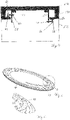
- the detail B in 2 and its enlargement in 3 show an adapter 28 which is screwed into a bore of the brake ring 22 via a screw 30 .
- the fitting piece 28 With the bore 32, the fitting piece 28 has a suitable opening for a countersunk screw 30.
- FIG. 4 shows a detailed view C 1 .
- the brake ring 22 with the fitting piece 28 which is fastened to the brake ring 22 via screws 30 can be seen.
- the transition area 34 runs in an arc, with the transition area 34 corresponding approximately to a quarter-circle arc.
- the arcuate course facilitates the insertion of the fitting piece 28 and also its connection to the brake ring 22.
- the quadrant arc is inclined towards the center of the fitting piece 28.
- FIG. 12 shows a perspective view of the yaw brake disc 10 with a raised fitting 28. Detail D of FIG figure 5 is in 6 shown and shows some of the screws 30 provided for connecting the adapter 28.
- FIG. 7 shows a schematic view of the structure in an azimuth slewing ring 50.
- the azimuth slewing ring 50 is provided between a tower head 52 and a machine carrier 54.
- the yaw brake disc 56 is arranged between the rotary connection 50 and the tower head 52, so that it is firmly connected to the tower.
- Holding devices 58 are provided on the machine support 54 on the side facing the tower head 52 . Each of the holding devices 58 is fixed to the nacelle and thus rotates relative to the azimuth brake disc 56. Each holding device 58 can also be equipped, for example, for the brake calipers that exert the braking torque on the azimuth brake disc 56. In 7 are no calipers shown.
- a milling tool 60 is attached to one or both holding devices 58 .
- the milling tool 60 has a holding arm 62 and a milling head 64.
- the arm 62 of the milling tool 60 can be adjusted relative to the area to be machined by means of adjustment means 61.
- a milling tool 68 operating on the tower-facing side of the azimuth brake disc is on the right-hand side of FIG 7 shown.
- the milling tool 68 can be adjusted in its position relative to the brake ring via a holding arm 70 and an adjustment means 66 .
Landscapes
- Engineering & Computer Science (AREA)
- General Engineering & Computer Science (AREA)
- Mechanical Engineering (AREA)
- Life Sciences & Earth Sciences (AREA)
- Sustainable Development (AREA)
- Sustainable Energy (AREA)
- Chemical & Material Sciences (AREA)
- Combustion & Propulsion (AREA)
- Braking Arrangements (AREA)
Description
- Die vorliegende Erfindung betrifft ein Verfahren zur Reparatur einer in einer Windenergieanlage montierten Azimutbremsscheibe sowie eine solche.
- Aus
EP 0 592 179 A1 ist ein Verfahren zur Aufarbeitung von Maschinenteilen, wie beispielsweise Kolben und Spindeln bekannt. Das Verfahren sieht vor, dass in einem verschlissenen Bereich eine spanende Bearbeitung erfolgt und ein umlaufendes Reparaturteil eingesetzt wird, das mit Elektronenstrahlschweißung befestigt wird. - Aus dem spanischen Erfindungspatent Nr. 10 721 ist es bekannt, Winkelprofile in ihrem Kantenbereich zu reparieren.
- Aus
GB 2,198,667 - Aus
GB 764,621 GB 764,622 -
US 2011/0142626 A1 beschreibt eine Azimutbremsscheibe, die im montierten Zustand gewartet werden kann. Die Azimutbremsscheibe weist einen kreisförmigen Trägerkörper auf, an dem eine Vielzahl von Segmenten der Azimutbremsscheibe lösbar angebracht ist. Für Wartungsarbeiten können Segmente einzeln ausgetauscht werden. - Aus
CN 103 785 989 A ist ein Reparaturverfahren für eine Azimutbremsscheibe einer Windenergieanlage bekannt geworden. Bei diesem Verfahren wird ein spanabhebendes Werkzeug an der Azimutbremse befestigt und die Azimutbremsscheibe bearbeitet. Bei einem Abtrag von mehr als 8 mm wird ein Einsatz in die Bremsscheibe eingeschweißt. - Der Erfindung liegt die Aufgabe zugrunde, ein Verfahren zur Reparatur einer in einer Windenergieanlage eingebauten Azimutbremsscheibe sowie eine solche bereitzustellen, das mit möglichst einfachen Mitteln eine Reparatur der Azimutbremsscheibe erlaubt.
- Erfindungsgemäß wird die Aufgabe durch ein Verfahren mit den Merkmalen aus Anspruch 1 gelöst. Vorteilhafte Ausgestaltungen bilden den Gegenstand der Unteransprüche.
- Das erfindungsgemäße Verfahren ist speziell ausgebildet, um eine Azimutbremsscheibe in einer Windenergieanlage zu reparieren. Die Windenergieanlage besitzt mindestens einen mit der Azimutbremsscheibe zusammenwirkenden Bremssattel und mindestens einen Azimutantrieb zur Nachführung eines Maschinenhauses entsprechend der Windrichtung. Durch Betätigen der Bremssättel an der Azimutbremsscheibe wird eine Drehbewegung des Maschinenhauses abgebremst. Durch den Azimutantrieb wird das Maschinenhaus um eine Turmlängsachse gedreht. Das erfindungsgemäße Verfahren sieht vor, ein spanend arbeitendes Werkzeug an einer an dem Maschinenhaus angeordneten Halteeinrichtung zu montieren. Mit der Montage des Werkzeugs nimmt diese eine genau definierte Position an dem Maschinenhaus ein. In einem darauffolgenden Schritt erfolgt eine spanende Bearbeitung des zu reparierenden Bereichs. Hierzu wird die Azimutbremsscheibe unter Drehbewegung des Maschinenhauses mit Hilfe des mindestens einen Azimutantriebs relativ zu dem gehaltenen Werkzeug bewegt. Nach Abschluss der spanenden Bearbeitung der Azimutbremsscheibe wird ein Passstück in den bearbeiteten Bereich eingebracht. Das eingebrachte Passstück wird mit der Azimutbremsscheibe mechanisch verbunden und nachfolgend erfolgt eine Oberflächenbearbeitung der Azimutbremsscheibe mit eingesetztem und mechanisch verbundenem Passstück. Das erfindungsgemäße Verfahren besitzt als Besonderheit, dass das spanend arbeitende Werkzeug fest an dem Maschinenhaus angeordnet ist. Hierdurch wird eine definierte Ausgangslage geschaffen, von der ausgehend, die Bearbeitung der Azimutbremsscheibe durchgeführt wird. Eine weitere Besonderheit bei dem Verfahren ist, dass die Azimutantriebe eingesetzt werden, um das spanend arbeitende Werkzeug entlang der Azimutbremsscheibe zu verfahren. Hierdurch wird eine Bearbeitung durchgeführt, die auch der späteren Bewegung der Azimutbremsscheibe im Betrieb der Windenergieanlage entspricht.
- In einer bevorzugten Ausgestaltung wird der Bereich an der Azimutbremsscheibe bis zu einer einheitlichen Tiefe abgetragen, die kleiner oder gleich der Dicke des Passstücks ist. Anders als bei Verfahren aus dem Stand der Technik, bei denen nach Bearbeitung des auszubessernden Werkstücks die Maße für das Passstück festgelegt werden, ist bei dem erfindungsgemäßen Verfahren durch das Passstück mindestens die Tiefe der Bearbeitung an der Azimutbremsscheibe vorgegeben. Es erfolgt die Bearbeitung nach den Vorgaben des Passstücks.
- In einer bevorzugten Ausgestaltung wird der Bereich in seinem Übergang zur Bremsscheibe in Umfangsrichtung mit einer gebogenen Kontur abgetragen. Der bearbeitete Bereich an der Azimutbremsscheibe besitzt in Umfangsrichtung der Brems scheibe einen Übergang zum nicht bearbeiteten Bereich der Azimutbremsscheibe. Dieser Übergang besitzt bevorzugt einen gebogenen Verlauf, der von einem geraden und in radialer Richtung verlaufenden Übergang abweicht.
- In einer weiteren bevorzugten Ausgestaltung sieht das erfindungsgemäße Verfahren vor, dass in den bearbeiteten Bereich der Azimutbremsscheibe Bohrungen eingebracht werden. Die eingebrachten Bohrungen fluchten mit den Bohrungen, die in dem Passstück vorgesehen sind. Bei dem erfindungsgemäßen Verfahren werden die Bohrungen in den bearbeiteten Bereich eingebracht, entsprechend den Bohrungen in dem Passstück. Hierbei kann das Passstück bereits in dem bearbeiteten Bereich eingesetzt sein, sodass die Bohrungen in dem Bereich und in dem Passstück gemeinsam eingebracht werden oder das Passstück besitzt bereits eine Bohrungsanordnung, die dann auf den bearbeiteten Bereich der Azimutbremsscheibe übertragen wird.
- In einer weiteren bevorzugten Ausgestaltung ist das Passstück mit der Azimutbremsscheibe verklebt. Alternativ oder zusätzlich kann das Passstück auch mit der Azimutbremsscheibe verschweißt werden.
- In einer bevorzugten Ausgestaltung weist die Halteeinrichtung ein Einstellmittel für die Position des spanend arbeitenden Werkzeugs relativ zu der Azimutbremsscheibe auf. Hierdurch kann beispielsweise die Breite des zu bearbeitenden Bereichs in radialer Richtung festgelegt werden. Ebenfalls kann auch die Tiefe, mit der der Bereich bearbeitet wird, festgelegt werden.
- Die erfindungsgemäße Aufgabe wird ebenfalls durch eine Azimutbremsscheibe mit einem Passstück gelöst, das in einen spanend abgetragenen Bereich der Azimutbremsscheibe eingesetzt ist oder über Befestigungsmittel mit der Azimutbremsscheibe verbunden ist, wobei die Oberfläche der Azimutbremsscheibe und des Passstücks in einem einheitlichen Arbeitsschritt bearbeitet, beispielsweise geschliffen wird. Die erfindungsgemäße Azimutbremsscheibe besitzt eine glatte Oberfläche, wobei ein Passstück in die Azimutbremsscheibe eingearbeitet ist.
- Die bevorzugte Azimutbremsscheibe besitzt ein Passstück, das die Form eines Ringabschnitts mit einer kreisbogenförmigen Innenkante und einer kreisbogenförmigen Außenkante sowie einem gebogenen Übergang an den in radialer Richtung außenliegenden Enden des Passstücks aufweist. Dabei ist der gebogene Übergang als Kontur so ausgebildet, dass die Bogenlänge des Passstücks für die Innenkante größer als für die Außenkante ist. Bei einer radial nach innen verlaufenden geraden Kontur wäre die Bogenlänge der Außenkante größer als die Bogenlänge der Innenkante. Der gebogene Übergang des Passstücks ist bevorzugt eine kreisförmige Innenkante der Azimutbremsscheibe. Das Passstück wird in dieser Ausgestaltung stets vom inneren Rand der Azimutbremsscheibe ausgehend eingesetzt.
- Ein bevorzugtes Ausführungsbeispiel wird nachfolgend erläutert. Es zeigen:
- Fig. 1
- eine Draufsicht auf eine Azimutbremsscheibe mit einem bereits bearbeiteten Bereich,
- Fig. 2
- einen Schnitt entlang der Linie A-A aus
Fig. 1 , - Fig. 3
- ein Detail B aus der Schnittansicht in
Fig. 2 , - Fig. 4
- ein Detail C aus der Draufsicht in
Fig. 1 , - Fig. 5
- eine perspektivische Ansicht einer Azimutbremsscheibe mit Passstück,
- Fig. 6
- ein Detail D aus
Fig. 5 und - Fig. 7
- eine Schnittansicht durch den Turmkopf.
-
Fig. 1 zeigt eine Azimutbremsscheibe 10 in einer Draufsicht. Die Azimutbremsscheibe 10 besitzt einen äußeren Befestigungsabschnitt 12 mit Befestigungsbohrungen 14. Die Befestigungsbohrungen 14 laufen gleichmäßig beabstandet an dem Befestigungsabschnitt um. Zusätzlich zu den gleichmäßig voneinander beabstandeten Befestigungsbohrungen gibt es zwölf zusätzliche Bohrungen 16, die ebenfalls in gleichmäßigem Abstand zueinander umlaufend an dem Befestigungsabschnitt angeordnet sind. Die Azimutbremsscheibe 10 besitzt ferner einen mittleren Übergangsbereich 18, der acht gleichmäßig über den Umfang verteilte Durchbrechungen 20 besitzt. - Innenliegend ist ein umlaufender Bremsring 22 vorgesehen. Der Bremsring 22 besitzt einen Innenradius und einen Außenradius, mit dem er an den Übergangsbereich 18 anschließt. Der Bremsring 22 bildet den Bereich der Azimutbremsscheibe 10, der mit den Bremssätteln, die die Bremskraft ausüben, zusammenwirkt. In Anlehnung an den englischen Ausdruck "brake caliper" wird auch der Ausdruck "Bremskaliber" für "Bremssattel" verwendet. Der Bremsring 22 besitzt bei dem in
Fig. 1 dargestellten Ausführungsbeispiel einen bearbeiteten Bereich 24, der sich ungefähr von 9 Uhr bis 1 Uhr auf dem Bremsring 22 erstreckt. Der bearbeitete Bereich ist mit Bohrungen 26 versehen, die in drei unterschiedlichen Radien in dem bearbeiteten Bereich 24 angeordnet sind. Hierbei liegen die radial innenliegenden Bohrungen 26a und die radial außenliegenden Bohrung 26c jeweils im Umfangsrichtung versetzt zueinander und zu der mittleren Bohrung 26b. -
Fig. 2 zeigt einen Schnitt entlang der Linie A-A ausFig. 1 . InFig. 2 ist der Befestigungsabschnitt 12 mit seiner Befestigungsbohrung 14 zu erkennen. Der Befestigungsabschnitt 12 besitzt in axialer Richtung die größte Höhe. Der Übergangsbereich 18 besitzt in axialer Richtung die geringste Höhe. Der Bremsring 22 besitzt eine größere axiale Höhe als der Übergangsbereich 18. - Das Detail B in
Fig. 2 und dessen Vergrößerung inFig. 3 zeigen ein Passstück 28, das über eine Schraube 30 in einer Bohrung des Bremsrings 22 verschraubt. Das Passstück 28 besitzt mit der Bohrung 32 eine passende Öffnung für eine Senkkopfschraube 30. -
Fig. 4 zeigt eine Detailansicht C ausFig. 1 . Zu erkennen ist der Bremsring 22 mit dem Passstück 28, das über Schrauben 30 an dem Bremsring 22 befestigt ist. Deutlich zu erkennen inFig. 4 ist, dass der Übergangsbereich 34 bogenförmig verläuft, wobei der Übergangsbereich 34 ungefähr einem Viertelkreisbogen entspricht. Der bogenförmige Verlauf erleichtert das Einsetzen des Passstücks 28 und auch seine Verbindung mit dem Bremsring 22. Der Viertelkreisbogen ist dabei zum Zentrum des Passstücks 28 hin geneigt. -
Fig. 5 zeigt in einer perspektivischen Ansicht die Azimutbremsscheibe 10 mit einem angehobenen Passstück 28. Das Detail D ausFig. 5 ist inFig. 6 dargestellt und zeigt einige der zur Verbindung des Passstücks 28 vorgesehenen Schrauben 30. -
Fig. 7 zeigt eine schematische Ansicht des Aufbaus in einer Azimutdrehverbindung 50. Die Azimutdrehverbindung 50 ist zwischen einem Turmkopf 52 und einem Maschinenträger 54 vorgesehen. Die Azimutbremsscheibe 56 ist in dem dargestellten Ausführungsbeispiel zwischen der Drehverbindung 50 und dem Turmkopf 52 angeordnet, so dass diese fest mit dem Turm verbunden ist. - An dem Maschinenträger 54 sind auf der zum Turmkopf 52 weisenden Seite Halteeinrichtungen 58 vorgesehen. Jeder der Halteeinrichtungen 58 ist maschinenhausfest und dreht sich somit gegenüber der Azimutbremsscheibe 56. Jede Halteeinrichtung 58 kann beispielsweise auch für die Bremssättel ausgestattet sein, die das Bremsmoment auf die Azimutbremsscheibe 56 ausüben. In
Fig. 7 sind keine Bremssättel dargestellt. An einer oder beiden Halteeinrichtungen 58 wird ein Fräswerkzeug 60 befestigt. Das Fräswerkzeug 60 verfügt über einen Haltearm 62 und einen Fräskopf 64. Über Einstellmittel 61 kann der Arm 62 des Fräswerkzeugs 60 relativ zu dem zu bearbeitenden Bereich eingestellt werden. Ein auf der dem Turm zugewandten Seite der Azimutbremsscheibe arbeitendes Fräswerkzeug 68 ist auf der rechten Seite derFig. 7 dargestellt. Auch hier kann das Fräswerkzeug 68 über einen Haltearm 70 und ein Einstellmittel 66 in seiner Lage relativ zum Bremsring eingestellt werden. -
- 10
- Azimutbremsscheibe
- 12
- Befestigungsabschnitt
- 14
- Befestigungsbohrungen
- 16
- zusätzliche Befestigungsbohrungen
- 18
- Übergangsbereich
- 20
- Durchbrechungen
- 22
- Bremsring
- 24
- bearbeiteter Bereich
- 26
- Bohrungen
- 26a
- radial innenliegende Bohrung
- 26b
- mittlere Bohrung
- 26c
- radial außenliegende Bohrung
- 28
- Passstück
- 30
- Schraube
- 32
- Bohrung
- 34
- Übergangsbereich
- 50
- Drehverbindung
- 52
- Turmkopf
- 54
- Maschinenträger
- 56
- Azimutbremsscheibe
- 58
- Halteeinrichtung
- 60
- Fräswerkzeug
- 61
- Einstellmittel
- 62
- Haltearm
- 64
- Fräskopf
- 66
- Einstellmittel
- 68
- Fräskopf
- 70
- Haltearm
Claims (5)
- Verfahren zur Reparatur einer in einer Windenergieanlage montierten Azimutbremsscheibe, wobei die Windenergieanlage mindestens einen mit der Azimutbremsscheibe zusammenwirkenden Bremssattel und mindestens einen Azimutantrieb zur Nachführung eines Maschinenhauses aufweist; das Verfahren weist folgende Schritte auf:- Montage mindestens eines spanend arbeitenden Werkzeugs an einer an dem Maschinenhaus angeordneten Halteeinrichtung, die Einstellmittel für die Position des spanend arbeitenden Werkzeugs relativ zu der Azimutbremsscheibe vorsieht,- spanende Bearbeitung eines zu bearbeitenden Bereichs der Azimutbremsscheibe unter Drehbewegung des Maschinenhauses mit Hilfe des mindestens einen Azimutantriebs, wobei der zu bearbeitende Bereich in seinem Übergang zur Azimutbremsscheibe mit einer gebogenen Kontur abgetragen wird,- Einbringen eines Passstücks in den bearbeiteten Bereich,- Verbinden des eingebrachten Passstücks mit der Azimutbremsscheibe, wobei in dem zu bearbeitenden Bereich der Azimutbremsscheibe Bohrungen eingebracht sind, die mit Bohrungen in dem Passstück fluchten, und das Passstück mit der Azimutbremsscheibe durch mehrere Schrauben verbunden wird, und- Bearbeiten der Oberfläche der Azimutbremsscheibe.
- Verfahren nach Anspruch 1, dadurch gekennzeichnet, dass der zu bearbeitende Bereich bis zu einer einheitlichen Tiefe abgetragen wird, die kleiner oder gleich der Dicke des Passstücks ist.
- Verfahren nach einem der Ansprüche 1 bis 2, dadurch gekennzeichnet, dass das Passstück mit der Azimutbremsscheibe verklebt wird.
- Azimutbremsscheibe einer Windenergieanlage mit einem Passstück, das in einem spanend bearbeiteten Bereich der Azimutbremsscheibe eingesetzt und über Befestigungsmittel mit der Azimutbremsscheibe verbunden ist, wobei die Oberfläche der Azimutbremsscheibe und des Passstücks in einem einheitlichen Arbeitsschritt bearbeitet ist, dadurch gekennzeichnet, dass das Passstück die Form eines Ringabschnitts mit einer kreisbogenförmigen Innenkante und einer kreisbogenförmigen Außenkante sowie gebogene Übergänge derart aufweist, dass die Bogenlänge des Passstücks für die Innenkante größer als für die Außenkante ist.
- Azimutbremsscheibe nach Anspruch 4, dadurch gekennzeichnet, dass die Innenkante des Passstücks mit einer kreisförmigen Innenkante der Azimutbremsscheibe zusammenfällt.
Priority Applications (3)
| Application Number | Priority Date | Filing Date | Title |
|---|---|---|---|
| EP16202370.9A EP3333418B1 (de) | 2016-12-06 | 2016-12-06 | Verfahren zur reparatur einer in einer windenergieanlage montierten azimutbremsscheibe sowie eine solche |
| ES16202370T ES2930465T3 (es) | 2016-12-06 | 2016-12-06 | Procedimiento para reparar un disco de freno de guiñada montado en un aerogenerador así como uno de este tipo |
| DK16202370.9T DK3333418T3 (en) | 2016-12-06 | 2016-12-06 | Method for repairing an azimuth brake disc mounted in a wind turbine and same |
Applications Claiming Priority (1)
| Application Number | Priority Date | Filing Date | Title |
|---|---|---|---|
| EP16202370.9A EP3333418B1 (de) | 2016-12-06 | 2016-12-06 | Verfahren zur reparatur einer in einer windenergieanlage montierten azimutbremsscheibe sowie eine solche |
Publications (2)
| Publication Number | Publication Date |
|---|---|
| EP3333418A1 EP3333418A1 (de) | 2018-06-13 |
| EP3333418B1 true EP3333418B1 (de) | 2022-09-14 |
Family
ID=57485408
Family Applications (1)
| Application Number | Title | Priority Date | Filing Date |
|---|---|---|---|
| EP16202370.9A Active EP3333418B1 (de) | 2016-12-06 | 2016-12-06 | Verfahren zur reparatur einer in einer windenergieanlage montierten azimutbremsscheibe sowie eine solche |
Country Status (3)
| Country | Link |
|---|---|
| EP (1) | EP3333418B1 (de) |
| DK (1) | DK3333418T3 (de) |
| ES (1) | ES2930465T3 (de) |
Families Citing this family (1)
| Publication number | Priority date | Publication date | Assignee | Title |
|---|---|---|---|---|
| CN110889781B (zh) * | 2019-12-04 | 2022-05-27 | 浙江大学 | 基于滑模控制的风电机组保性能最大功率跟踪方法 |
Citations (1)
| Publication number | Priority date | Publication date | Assignee | Title |
|---|---|---|---|---|
| ES2389359A1 (es) * | 2010-02-02 | 2012-10-25 | Acciona Windpower, S.A. | Procedimiento de reparación del sistema de frenado del mecanismo de orientación relativa entre la góndola y la torre de una turbina eólica. |
Family Cites Families (9)
| Publication number | Priority date | Publication date | Assignee | Title |
|---|---|---|---|---|
| ES10721U (es) | 1944-11-03 | 1944-11-16 | Laboz Borillo Luís | Sobre con dispositivo para su apetura |
| GB764621A (en) | 1953-12-07 | 1956-12-28 | Svenska Metalock Aktiebolag | Improvements in or relating to the repairing of fractured metal articles |
| GB764622A (en) | 1953-12-07 | 1956-12-28 | Svenska Metalock Aktiebolag | Improvements in or relating to the repairing of fractured metal articles |
| GB2198667B (en) | 1986-12-20 | 1991-08-07 | Refurbished Turbine Components | Parts for and methods of repairing machines |
| GB2271521B (en) | 1992-10-06 | 1996-01-31 | Metalock | Reconditioning engine parts |
| KR101200701B1 (ko) | 2009-04-02 | 2012-11-13 | 클립퍼 윈드파워, 인코포레이티드 | 너셀을 분리하지 않고 용이하게 수선할 수 있는 요 브레이크 디스크 세그먼트 |
| CN101543945A (zh) * | 2009-04-10 | 2009-09-30 | 沪东重机有限公司 | 一种船用柴油机机座主轴承座上铸造缺陷的修复方法 |
| CN202431438U (zh) * | 2011-12-22 | 2012-09-12 | 华锐风电科技(集团)股份有限公司 | 风力发电机组偏航系统制动盘装置 |
| CN103785989B (zh) * | 2014-01-23 | 2016-05-18 | 广东明阳风电产业集团有限公司 | 一种风力发电机组的偏航制动盘高空修复方法 |
-
2016
- 2016-12-06 EP EP16202370.9A patent/EP3333418B1/de active Active
- 2016-12-06 ES ES16202370T patent/ES2930465T3/es active Active
- 2016-12-06 DK DK16202370.9T patent/DK3333418T3/da active
Patent Citations (1)
| Publication number | Priority date | Publication date | Assignee | Title |
|---|---|---|---|---|
| ES2389359A1 (es) * | 2010-02-02 | 2012-10-25 | Acciona Windpower, S.A. | Procedimiento de reparación del sistema de frenado del mecanismo de orientación relativa entre la góndola y la torre de una turbina eólica. |
Also Published As
| Publication number | Publication date |
|---|---|
| ES2930465T3 (es) | 2022-12-14 |
| EP3333418A1 (de) | 2018-06-13 |
| DK3333418T3 (en) | 2022-12-12 |
Similar Documents
| Publication | Publication Date | Title |
|---|---|---|
| EP2019219B1 (de) | Verbindung zweier um eine gemeinsame Rotationsachse drehbare Körper | |
| EP2304261B1 (de) | Verfahren zum herstellen eines bremssattels, bearbeitungswerkzeug zum ausführen des verfahrens, mit dem verfahren hergestellter bremssattel sowie scheibenbremse mit einem solchen sattel | |
| WO2011045435A1 (de) | Lageranordnung für eine windturbine | |
| EP2999565B1 (de) | Werkzeugaufnahme | |
| DE102013015252A1 (de) | Kühlmittelzufuhr und damit ausgestattete Wälzschälmaschine sowie damit ausgeführtes Wälzschälverfahren | |
| EP0451360A2 (de) | Spannvorrichtung zum Einspannen eines Werkzeuges in einem Werkzeugträger | |
| WO1994021428A1 (de) | Anordnung zur zentrierten und axial fixierten aufnahme eines rotierenden körpers und zugehöriger adapter | |
| DE3905168C1 (de) | ||
| EP3347573A1 (de) | Dummy-radscheibe und verfahren zum bearbeiten von schaufeln | |
| EP3501764B1 (de) | Verwendung eines trennschneiders mit tiefenanschlag | |
| EP3016770B1 (de) | Wechselkopfsystem für die metallbearbeitung | |
| DE102017113396A1 (de) | Arbeitsspindel mit Radialklemmeinrichtung | |
| EP0328958B1 (de) | Vorrichtung zum Bearbeiten von rotationssymmetrischen Werkstückflächen | |
| EP1716817A1 (de) | Medizinisches, insbesondere dentalmedizinisches Handstück | |
| EP3333418A1 (de) | Verfahren zur reparatur einer in einer windenergieanlage montierten azimutbremsscheibe sowie eine solche | |
| EP1943098B1 (de) | Fräs- und/oder drehwerkzeug | |
| EP3090831B1 (de) | Werkzeugschnellwechselsystem mit späneleiteinrichtung | |
| EP3638918B1 (de) | Reibringkörper, reibringsatz zur anordnung an den radsteg eines schienenrads, sowie schienenradbremse | |
| AT413047B (de) | Träger für eine fliegende schneiddiskenlagerung | |
| DE102019126348B4 (de) | Azimutbremseinrichtung | |
| EP4188639B1 (de) | System zum ausrichten eines werkstücks relativ zu einem maschinenteil | |
| DE102012004605B4 (de) | Verfahren und Werkzeug zur spanenden Bearbeitung von Lagerstellen in einem Bremssattel | |
| AT405081B (de) | Laufrad für eine freistrahlturbine | |
| WO2017097636A1 (de) | Verfahren zur dauerhaften befestigung von nocken auf einem trägerrohr | |
| WO1988005359A1 (fr) | Dispositif pour relier deux pieces configurees de maniere a etre sensiblement symetriques en rotation dans la region de liaison, notamment une tete d'outil avec un porte-outil dans des machines-outils |
Legal Events
| Date | Code | Title | Description |
|---|---|---|---|
| STAA | Information on the status of an ep patent application or granted ep patent |
Free format text: STATUS: EXAMINATION IS IN PROGRESS |
|
| PUAI | Public reference made under article 153(3) epc to a published international application that has entered the european phase |
Free format text: ORIGINAL CODE: 0009012 |
|
| 17P | Request for examination filed |
Effective date: 20171113 |
|
| AK | Designated contracting states |
Kind code of ref document: A1 Designated state(s): AL AT BE BG CH CY CZ DE DK EE ES FI FR GB GR HR HU IE IS IT LI LT LU LV MC MK MT NL NO PL PT RO RS SE SI SK SM TR |
|
| AX | Request for extension of the european patent |
Extension state: BA ME |
|
| RAP1 | Party data changed (applicant data changed or rights of an application transferred) |
Owner name: NORDEX ENERGY SE & CO. KG |
|
| RIC1 | Information provided on ipc code assigned before grant |
Ipc: F03D 80/50 20160101AFI20210219BHEP |
|
| GRAP | Despatch of communication of intention to grant a patent |
Free format text: ORIGINAL CODE: EPIDOSNIGR1 |
|
| STAA | Information on the status of an ep patent application or granted ep patent |
Free format text: STATUS: GRANT OF PATENT IS INTENDED |
|
| INTG | Intention to grant announced |
Effective date: 20210413 |
|
| GRAJ | Information related to disapproval of communication of intention to grant by the applicant or resumption of examination proceedings by the epo deleted |
Free format text: ORIGINAL CODE: EPIDOSDIGR1 |
|
| STAA | Information on the status of an ep patent application or granted ep patent |
Free format text: STATUS: EXAMINATION IS IN PROGRESS |
|
| INTC | Intention to grant announced (deleted) | ||
| GRAP | Despatch of communication of intention to grant a patent |
Free format text: ORIGINAL CODE: EPIDOSNIGR1 |
|
| STAA | Information on the status of an ep patent application or granted ep patent |
Free format text: STATUS: GRANT OF PATENT IS INTENDED |
|
| INTG | Intention to grant announced |
Effective date: 20211112 |
|
| GRAJ | Information related to disapproval of communication of intention to grant by the applicant or resumption of examination proceedings by the epo deleted |
Free format text: ORIGINAL CODE: EPIDOSDIGR1 |
|
| STAA | Information on the status of an ep patent application or granted ep patent |
Free format text: STATUS: EXAMINATION IS IN PROGRESS |
|
| INTC | Intention to grant announced (deleted) | ||
| GRAP | Despatch of communication of intention to grant a patent |
Free format text: ORIGINAL CODE: EPIDOSNIGR1 |
|
| STAA | Information on the status of an ep patent application or granted ep patent |
Free format text: STATUS: GRANT OF PATENT IS INTENDED |
|
| INTG | Intention to grant announced |
Effective date: 20220422 |
|
| GRAS | Grant fee paid |
Free format text: ORIGINAL CODE: EPIDOSNIGR3 |
|
| GRAA | (expected) grant |
Free format text: ORIGINAL CODE: 0009210 |
|
| STAA | Information on the status of an ep patent application or granted ep patent |
Free format text: STATUS: THE PATENT HAS BEEN GRANTED |
|
| AK | Designated contracting states |
Kind code of ref document: B1 Designated state(s): AL AT BE BG CH CY CZ DE DK EE ES FI FR GB GR HR HU IE IS IT LI LT LU LV MC MK MT NL NO PL PT RO RS SE SI SK SM TR |
|
| REG | Reference to a national code |
Ref country code: GB Ref legal event code: FG4D Free format text: NOT ENGLISH |
|
| REG | Reference to a national code |
Ref country code: CH Ref legal event code: EP |
|
| REG | Reference to a national code |
Ref country code: DE Ref legal event code: R096 Ref document number: 502016015271 Country of ref document: DE |
|
| REG | Reference to a national code |
Ref country code: IE Ref legal event code: FG4D Free format text: LANGUAGE OF EP DOCUMENT: GERMAN |
|
| REG | Reference to a national code |
Ref country code: AT Ref legal event code: REF Ref document number: 1518838 Country of ref document: AT Kind code of ref document: T Effective date: 20221015 |
|
| REG | Reference to a national code |
Ref country code: DK Ref legal event code: T3 Effective date: 20221208 |
|
| REG | Reference to a national code |
Ref country code: ES Ref legal event code: FG2A Ref document number: 2930465 Country of ref document: ES Kind code of ref document: T3 Effective date: 20221214 |
|
| REG | Reference to a national code |
Ref country code: LT Ref legal event code: MG9D |
|
| REG | Reference to a national code |
Ref country code: NL Ref legal event code: MP Effective date: 20220914 |
|
| PG25 | Lapsed in a contracting state [announced via postgrant information from national office to epo] |
Ref country code: SE Free format text: LAPSE BECAUSE OF FAILURE TO SUBMIT A TRANSLATION OF THE DESCRIPTION OR TO PAY THE FEE WITHIN THE PRESCRIBED TIME-LIMIT Effective date: 20220914 Ref country code: RS Free format text: LAPSE BECAUSE OF FAILURE TO SUBMIT A TRANSLATION OF THE DESCRIPTION OR TO PAY THE FEE WITHIN THE PRESCRIBED TIME-LIMIT Effective date: 20220914 Ref country code: NO Free format text: LAPSE BECAUSE OF FAILURE TO SUBMIT A TRANSLATION OF THE DESCRIPTION OR TO PAY THE FEE WITHIN THE PRESCRIBED TIME-LIMIT Effective date: 20221214 Ref country code: LV Free format text: LAPSE BECAUSE OF FAILURE TO SUBMIT A TRANSLATION OF THE DESCRIPTION OR TO PAY THE FEE WITHIN THE PRESCRIBED TIME-LIMIT Effective date: 20220914 Ref country code: LT Free format text: LAPSE BECAUSE OF FAILURE TO SUBMIT A TRANSLATION OF THE DESCRIPTION OR TO PAY THE FEE WITHIN THE PRESCRIBED TIME-LIMIT Effective date: 20220914 Ref country code: FI Free format text: LAPSE BECAUSE OF FAILURE TO SUBMIT A TRANSLATION OF THE DESCRIPTION OR TO PAY THE FEE WITHIN THE PRESCRIBED TIME-LIMIT Effective date: 20220914 |
|
| PG25 | Lapsed in a contracting state [announced via postgrant information from national office to epo] |
Ref country code: HR Free format text: LAPSE BECAUSE OF FAILURE TO SUBMIT A TRANSLATION OF THE DESCRIPTION OR TO PAY THE FEE WITHIN THE PRESCRIBED TIME-LIMIT Effective date: 20220914 Ref country code: GR Free format text: LAPSE BECAUSE OF FAILURE TO SUBMIT A TRANSLATION OF THE DESCRIPTION OR TO PAY THE FEE WITHIN THE PRESCRIBED TIME-LIMIT Effective date: 20221215 |
|
| PG25 | Lapsed in a contracting state [announced via postgrant information from national office to epo] |
Ref country code: SM Free format text: LAPSE BECAUSE OF FAILURE TO SUBMIT A TRANSLATION OF THE DESCRIPTION OR TO PAY THE FEE WITHIN THE PRESCRIBED TIME-LIMIT Effective date: 20220914 Ref country code: RO Free format text: LAPSE BECAUSE OF FAILURE TO SUBMIT A TRANSLATION OF THE DESCRIPTION OR TO PAY THE FEE WITHIN THE PRESCRIBED TIME-LIMIT Effective date: 20220914 Ref country code: PT Free format text: LAPSE BECAUSE OF FAILURE TO SUBMIT A TRANSLATION OF THE DESCRIPTION OR TO PAY THE FEE WITHIN THE PRESCRIBED TIME-LIMIT Effective date: 20230116 Ref country code: CZ Free format text: LAPSE BECAUSE OF FAILURE TO SUBMIT A TRANSLATION OF THE DESCRIPTION OR TO PAY THE FEE WITHIN THE PRESCRIBED TIME-LIMIT Effective date: 20220914 |
|
| PG25 | Lapsed in a contracting state [announced via postgrant information from national office to epo] |
Ref country code: SK Free format text: LAPSE BECAUSE OF FAILURE TO SUBMIT A TRANSLATION OF THE DESCRIPTION OR TO PAY THE FEE WITHIN THE PRESCRIBED TIME-LIMIT Effective date: 20220914 Ref country code: PL Free format text: LAPSE BECAUSE OF FAILURE TO SUBMIT A TRANSLATION OF THE DESCRIPTION OR TO PAY THE FEE WITHIN THE PRESCRIBED TIME-LIMIT Effective date: 20220914 Ref country code: IS Free format text: LAPSE BECAUSE OF FAILURE TO SUBMIT A TRANSLATION OF THE DESCRIPTION OR TO PAY THE FEE WITHIN THE PRESCRIBED TIME-LIMIT Effective date: 20230114 Ref country code: EE Free format text: LAPSE BECAUSE OF FAILURE TO SUBMIT A TRANSLATION OF THE DESCRIPTION OR TO PAY THE FEE WITHIN THE PRESCRIBED TIME-LIMIT Effective date: 20220914 |
|
| REG | Reference to a national code |
Ref country code: DE Ref legal event code: R097 Ref document number: 502016015271 Country of ref document: DE |
|
| PG25 | Lapsed in a contracting state [announced via postgrant information from national office to epo] |
Ref country code: NL Free format text: LAPSE BECAUSE OF FAILURE TO SUBMIT A TRANSLATION OF THE DESCRIPTION OR TO PAY THE FEE WITHIN THE PRESCRIBED TIME-LIMIT Effective date: 20220914 Ref country code: AL Free format text: LAPSE BECAUSE OF FAILURE TO SUBMIT A TRANSLATION OF THE DESCRIPTION OR TO PAY THE FEE WITHIN THE PRESCRIBED TIME-LIMIT Effective date: 20220914 |
|
| P01 | Opt-out of the competence of the unified patent court (upc) registered |
Effective date: 20230602 |
|
| PLBE | No opposition filed within time limit |
Free format text: ORIGINAL CODE: 0009261 |
|
| STAA | Information on the status of an ep patent application or granted ep patent |
Free format text: STATUS: NO OPPOSITION FILED WITHIN TIME LIMIT |
|
| REG | Reference to a national code |
Ref country code: CH Ref legal event code: PL |
|
| 26N | No opposition filed |
Effective date: 20230615 |
|
| GBPC | Gb: european patent ceased through non-payment of renewal fee |
Effective date: 20221214 |
|
| REG | Reference to a national code |
Ref country code: BE Ref legal event code: MM Effective date: 20221231 |
|
| PG25 | Lapsed in a contracting state [announced via postgrant information from national office to epo] |
Ref country code: SI Free format text: LAPSE BECAUSE OF FAILURE TO SUBMIT A TRANSLATION OF THE DESCRIPTION OR TO PAY THE FEE WITHIN THE PRESCRIBED TIME-LIMIT Effective date: 20220914 Ref country code: LU Free format text: LAPSE BECAUSE OF NON-PAYMENT OF DUE FEES Effective date: 20221206 |
|
| PG25 | Lapsed in a contracting state [announced via postgrant information from national office to epo] |
Ref country code: LI Free format text: LAPSE BECAUSE OF NON-PAYMENT OF DUE FEES Effective date: 20221231 Ref country code: IE Free format text: LAPSE BECAUSE OF NON-PAYMENT OF DUE FEES Effective date: 20221206 Ref country code: GB Free format text: LAPSE BECAUSE OF NON-PAYMENT OF DUE FEES Effective date: 20221214 Ref country code: CH Free format text: LAPSE BECAUSE OF NON-PAYMENT OF DUE FEES Effective date: 20221231 |
|
| PG25 | Lapsed in a contracting state [announced via postgrant information from national office to epo] |
Ref country code: FR Free format text: LAPSE BECAUSE OF NON-PAYMENT OF DUE FEES Effective date: 20221231 Ref country code: BE Free format text: LAPSE BECAUSE OF NON-PAYMENT OF DUE FEES Effective date: 20221231 |
|
| REG | Reference to a national code |
Ref country code: AT Ref legal event code: MM01 Ref document number: 1518838 Country of ref document: AT Kind code of ref document: T Effective date: 20221206 |
|
| PG25 | Lapsed in a contracting state [announced via postgrant information from national office to epo] |
Ref country code: HU Free format text: LAPSE BECAUSE OF FAILURE TO SUBMIT A TRANSLATION OF THE DESCRIPTION OR TO PAY THE FEE WITHIN THE PRESCRIBED TIME-LIMIT; INVALID AB INITIO Effective date: 20161206 |
|
| PG25 | Lapsed in a contracting state [announced via postgrant information from national office to epo] |
Ref country code: AT Free format text: LAPSE BECAUSE OF NON-PAYMENT OF DUE FEES Effective date: 20221206 |
|
| PG25 | Lapsed in a contracting state [announced via postgrant information from national office to epo] |
Ref country code: CY Free format text: LAPSE BECAUSE OF FAILURE TO SUBMIT A TRANSLATION OF THE DESCRIPTION OR TO PAY THE FEE WITHIN THE PRESCRIBED TIME-LIMIT Effective date: 20220914 Ref country code: AT Free format text: LAPSE BECAUSE OF NON-PAYMENT OF DUE FEES Effective date: 20221206 |
|
| PG25 | Lapsed in a contracting state [announced via postgrant information from national office to epo] |
Ref country code: MK Free format text: LAPSE BECAUSE OF FAILURE TO SUBMIT A TRANSLATION OF THE DESCRIPTION OR TO PAY THE FEE WITHIN THE PRESCRIBED TIME-LIMIT Effective date: 20220914 Ref country code: IT Free format text: LAPSE BECAUSE OF FAILURE TO SUBMIT A TRANSLATION OF THE DESCRIPTION OR TO PAY THE FEE WITHIN THE PRESCRIBED TIME-LIMIT Effective date: 20220914 |
|
| PG25 | Lapsed in a contracting state [announced via postgrant information from national office to epo] |
Ref country code: MC Free format text: LAPSE BECAUSE OF FAILURE TO SUBMIT A TRANSLATION OF THE DESCRIPTION OR TO PAY THE FEE WITHIN THE PRESCRIBED TIME-LIMIT Effective date: 20220914 |
|
| PG25 | Lapsed in a contracting state [announced via postgrant information from national office to epo] |
Ref country code: TR Free format text: LAPSE BECAUSE OF FAILURE TO SUBMIT A TRANSLATION OF THE DESCRIPTION OR TO PAY THE FEE WITHIN THE PRESCRIBED TIME-LIMIT Effective date: 20220914 Ref country code: MC Free format text: LAPSE BECAUSE OF FAILURE TO SUBMIT A TRANSLATION OF THE DESCRIPTION OR TO PAY THE FEE WITHIN THE PRESCRIBED TIME-LIMIT Effective date: 20220914 |
|
| PG25 | Lapsed in a contracting state [announced via postgrant information from national office to epo] |
Ref country code: BG Free format text: LAPSE BECAUSE OF FAILURE TO SUBMIT A TRANSLATION OF THE DESCRIPTION OR TO PAY THE FEE WITHIN THE PRESCRIBED TIME-LIMIT Effective date: 20220914 |
|
| PG25 | Lapsed in a contracting state [announced via postgrant information from national office to epo] |
Ref country code: MT Free format text: LAPSE BECAUSE OF FAILURE TO SUBMIT A TRANSLATION OF THE DESCRIPTION OR TO PAY THE FEE WITHIN THE PRESCRIBED TIME-LIMIT Effective date: 20220914 |
|
| PGFP | Annual fee paid to national office [announced via postgrant information from national office to epo] |
Ref country code: DK Payment date: 20251217 Year of fee payment: 10 |
|
| PGFP | Annual fee paid to national office [announced via postgrant information from national office to epo] |
Ref country code: ES Payment date: 20260119 Year of fee payment: 10 |
|
| PGFP | Annual fee paid to national office [announced via postgrant information from national office to epo] |
Ref country code: DE Payment date: 20251222 Year of fee payment: 10 |