EP3333403A1 - Grenzschichtanregung nach dem gebläse einer gasturbine - Google Patents
Grenzschichtanregung nach dem gebläse einer gasturbine Download PDFInfo
- Publication number
- EP3333403A1 EP3333403A1 EP17206030.3A EP17206030A EP3333403A1 EP 3333403 A1 EP3333403 A1 EP 3333403A1 EP 17206030 A EP17206030 A EP 17206030A EP 3333403 A1 EP3333403 A1 EP 3333403A1
- Authority
- EP
- European Patent Office
- Prior art keywords
- boundary layer
- fan
- engine
- turbine
- layer ingestion
- Prior art date
- Legal status (The legal status is an assumption and is not a legal conclusion. Google has not performed a legal analysis and makes no representation as to the accuracy of the status listed.)
- Granted
Links
Images



Classifications
-
- B—PERFORMING OPERATIONS; TRANSPORTING
- B64—AIRCRAFT; AVIATION; COSMONAUTICS
- B64C—AEROPLANES; HELICOPTERS
- B64C1/00—Fuselages; Constructional features common to fuselages, wings, stabilising surfaces or the like
- B64C1/16—Fuselages; Constructional features common to fuselages, wings, stabilising surfaces or the like specially adapted for mounting power plant
-
- B—PERFORMING OPERATIONS; TRANSPORTING
- B64—AIRCRAFT; AVIATION; COSMONAUTICS
- B64C—AEROPLANES; HELICOPTERS
- B64C21/00—Influencing air flow over aircraft surfaces by affecting boundary layer flow
- B64C21/01—Boundary layer ingestion [BLI] propulsion
-
- B—PERFORMING OPERATIONS; TRANSPORTING
- B64—AIRCRAFT; AVIATION; COSMONAUTICS
- B64D—EQUIPMENT FOR FITTING IN OR TO AIRCRAFT; FLIGHT SUITS; PARACHUTES; ARRANGEMENT OR MOUNTING OF POWER PLANTS OR PROPULSION TRANSMISSIONS IN AIRCRAFT
- B64D27/00—Arrangement or mounting of power plants in aircraft; Aircraft characterised by the type or position of power plants
- B64D27/02—Aircraft characterised by the type or position of power plants
- B64D27/16—Aircraft characterised by the type or position of power plants of jet type
- B64D27/20—Aircraft characterised by the type or position of power plants of jet type within, or attached to, fuselages
-
- B—PERFORMING OPERATIONS; TRANSPORTING
- B64—AIRCRAFT; AVIATION; COSMONAUTICS
- B64D—EQUIPMENT FOR FITTING IN OR TO AIRCRAFT; FLIGHT SUITS; PARACHUTES; ARRANGEMENT OR MOUNTING OF POWER PLANTS OR PROPULSION TRANSMISSIONS IN AIRCRAFT
- B64D33/00—Arrangement in aircraft of power plant parts or auxiliaries not otherwise provided for
- B64D33/02—Arrangement in aircraft of power plant parts or auxiliaries not otherwise provided for of combustion air intakes
-
- F—MECHANICAL ENGINEERING; LIGHTING; HEATING; WEAPONS; BLASTING
- F02—COMBUSTION ENGINES; HOT-GAS OR COMBUSTION-PRODUCT ENGINE PLANTS
- F02C—GAS-TURBINE PLANTS; AIR INTAKES FOR JET-PROPULSION PLANTS; CONTROLLING FUEL SUPPLY IN AIR-BREATHING JET-PROPULSION PLANTS
- F02C3/00—Gas-turbine plants characterised by the use of combustion products as the working fluid
- F02C3/04—Gas-turbine plants characterised by the use of combustion products as the working fluid having a turbine driving a compressor
- F02C3/10—Gas-turbine plants characterised by the use of combustion products as the working fluid having a turbine driving a compressor with another turbine driving an output shaft but not driving the compressor
-
- F—MECHANICAL ENGINEERING; LIGHTING; HEATING; WEAPONS; BLASTING
- F02—COMBUSTION ENGINES; HOT-GAS OR COMBUSTION-PRODUCT ENGINE PLANTS
- F02C—GAS-TURBINE PLANTS; AIR INTAKES FOR JET-PROPULSION PLANTS; CONTROLLING FUEL SUPPLY IN AIR-BREATHING JET-PROPULSION PLANTS
- F02C3/00—Gas-turbine plants characterised by the use of combustion products as the working fluid
- F02C3/20—Gas-turbine plants characterised by the use of combustion products as the working fluid using a special fuel, oxidant, or dilution fluid to generate the combustion products
-
- F—MECHANICAL ENGINEERING; LIGHTING; HEATING; WEAPONS; BLASTING
- F02—COMBUSTION ENGINES; HOT-GAS OR COMBUSTION-PRODUCT ENGINE PLANTS
- F02C—GAS-TURBINE PLANTS; AIR INTAKES FOR JET-PROPULSION PLANTS; CONTROLLING FUEL SUPPLY IN AIR-BREATHING JET-PROPULSION PLANTS
- F02C6/00—Plural gas-turbine plants; Combinations of gas-turbine plants with other apparatus; Adaptations of gas-turbine plants for special use
- F02C6/04—Gas-turbine plants providing heated or pressurised working fluid for other apparatus, e.g. without mechanical power output
- F02C6/06—Gas-turbine plants providing heated or pressurised working fluid for other apparatus, e.g. without mechanical power output providing compressed gas
- F02C6/08—Gas-turbine plants providing heated or pressurised working fluid for other apparatus, e.g. without mechanical power output providing compressed gas the gas being bled from the gas-turbine compressor
-
- F—MECHANICAL ENGINEERING; LIGHTING; HEATING; WEAPONS; BLASTING
- F02—COMBUSTION ENGINES; HOT-GAS OR COMBUSTION-PRODUCT ENGINE PLANTS
- F02C—GAS-TURBINE PLANTS; AIR INTAKES FOR JET-PROPULSION PLANTS; CONTROLLING FUEL SUPPLY IN AIR-BREATHING JET-PROPULSION PLANTS
- F02C7/00—Features, components parts, details or accessories, not provided for in, or of interest apart form groups F02C1/00 - F02C6/00; Air intakes for jet-propulsion plants
- F02C7/36—Power transmission arrangements between the different shafts of the gas turbine plant, or between the gas-turbine plant and the power user
-
- F—MECHANICAL ENGINEERING; LIGHTING; HEATING; WEAPONS; BLASTING
- F02—COMBUSTION ENGINES; HOT-GAS OR COMBUSTION-PRODUCT ENGINE PLANTS
- F02K—JET-PROPULSION PLANTS
- F02K3/00—Plants including a gas turbine driving a compressor or a ducted fan
- F02K3/02—Plants including a gas turbine driving a compressor or a ducted fan in which part of the working fluid by-passes the turbine and combustion chamber
- F02K3/04—Plants including a gas turbine driving a compressor or a ducted fan in which part of the working fluid by-passes the turbine and combustion chamber the plant including ducted fans, i.e. fans with high volume, low pressure outputs, for augmenting the jet thrust, e.g. of double-flow type
- F02K3/06—Plants including a gas turbine driving a compressor or a ducted fan in which part of the working fluid by-passes the turbine and combustion chamber the plant including ducted fans, i.e. fans with high volume, low pressure outputs, for augmenting the jet thrust, e.g. of double-flow type with front fan
-
- F—MECHANICAL ENGINEERING; LIGHTING; HEATING; WEAPONS; BLASTING
- F02—COMBUSTION ENGINES; HOT-GAS OR COMBUSTION-PRODUCT ENGINE PLANTS
- F02K—JET-PROPULSION PLANTS
- F02K3/00—Plants including a gas turbine driving a compressor or a ducted fan
- F02K3/02—Plants including a gas turbine driving a compressor or a ducted fan in which part of the working fluid by-passes the turbine and combustion chamber
- F02K3/04—Plants including a gas turbine driving a compressor or a ducted fan in which part of the working fluid by-passes the turbine and combustion chamber the plant including ducted fans, i.e. fans with high volume, low pressure outputs, for augmenting the jet thrust, e.g. of double-flow type
- F02K3/062—Plants including a gas turbine driving a compressor or a ducted fan in which part of the working fluid by-passes the turbine and combustion chamber the plant including ducted fans, i.e. fans with high volume, low pressure outputs, for augmenting the jet thrust, e.g. of double-flow type with aft fan
-
- B—PERFORMING OPERATIONS; TRANSPORTING
- B64—AIRCRAFT; AVIATION; COSMONAUTICS
- B64C—AEROPLANES; HELICOPTERS
- B64C2230/00—Boundary layer controls
- B64C2230/04—Boundary layer controls by actively generating fluid flow
-
- B—PERFORMING OPERATIONS; TRANSPORTING
- B64—AIRCRAFT; AVIATION; COSMONAUTICS
- B64D—EQUIPMENT FOR FITTING IN OR TO AIRCRAFT; FLIGHT SUITS; PARACHUTES; ARRANGEMENT OR MOUNTING OF POWER PLANTS OR PROPULSION TRANSMISSIONS IN AIRCRAFT
- B64D33/00—Arrangement in aircraft of power plant parts or auxiliaries not otherwise provided for
- B64D33/02—Arrangement in aircraft of power plant parts or auxiliaries not otherwise provided for of combustion air intakes
- B64D2033/0226—Arrangement in aircraft of power plant parts or auxiliaries not otherwise provided for of combustion air intakes comprising boundary layer control means
-
- F—MECHANICAL ENGINEERING; LIGHTING; HEATING; WEAPONS; BLASTING
- F05—INDEXING SCHEMES RELATING TO ENGINES OR PUMPS IN VARIOUS SUBCLASSES OF CLASSES F01-F04
- F05D—INDEXING SCHEME FOR ASPECTS RELATING TO NON-POSITIVE-DISPLACEMENT MACHINES OR ENGINES, GAS-TURBINES OR JET-PROPULSION PLANTS
- F05D2220/00—Application
- F05D2220/30—Application in turbines
- F05D2220/32—Application in turbines in gas turbines
- F05D2220/323—Application in turbines in gas turbines for aircraft propulsion, e.g. jet engines
-
- F—MECHANICAL ENGINEERING; LIGHTING; HEATING; WEAPONS; BLASTING
- F05—INDEXING SCHEMES RELATING TO ENGINES OR PUMPS IN VARIOUS SUBCLASSES OF CLASSES F01-F04
- F05D—INDEXING SCHEME FOR ASPECTS RELATING TO NON-POSITIVE-DISPLACEMENT MACHINES OR ENGINES, GAS-TURBINES OR JET-PROPULSION PLANTS
- F05D2220/00—Application
- F05D2220/50—Application for auxiliary power units (APU's)
-
- F—MECHANICAL ENGINEERING; LIGHTING; HEATING; WEAPONS; BLASTING
- F05—INDEXING SCHEMES RELATING TO ENGINES OR PUMPS IN VARIOUS SUBCLASSES OF CLASSES F01-F04
- F05D—INDEXING SCHEME FOR ASPECTS RELATING TO NON-POSITIVE-DISPLACEMENT MACHINES OR ENGINES, GAS-TURBINES OR JET-PROPULSION PLANTS
- F05D2220/00—Application
- F05D2220/70—Application in combination with
- F05D2220/76—Application in combination with an electrical generator
-
- Y—GENERAL TAGGING OF NEW TECHNOLOGICAL DEVELOPMENTS; GENERAL TAGGING OF CROSS-SECTIONAL TECHNOLOGIES SPANNING OVER SEVERAL SECTIONS OF THE IPC; TECHNICAL SUBJECTS COVERED BY FORMER USPC CROSS-REFERENCE ART COLLECTIONS [XRACs] AND DIGESTS
- Y02—TECHNOLOGIES OR APPLICATIONS FOR MITIGATION OR ADAPTATION AGAINST CLIMATE CHANGE
- Y02T—CLIMATE CHANGE MITIGATION TECHNOLOGIES RELATED TO TRANSPORTATION
- Y02T50/00—Aeronautics or air transport
- Y02T50/10—Drag reduction
Definitions
- the present disclosure relates generally to aft fan gas turbine engines, and more specifically to an aft fan gas turbine engine configured to energize a boundary layer of a corresponding vehicle.
- Aircraft such as those utilized by commercial airlines, typically include two or more gas turbine engines mounted in or under the wings of the aircraft.
- the engines generate thrust, propelling the aircraft forward and allowing operation of the aircraft.
- a typical engine utilized in this configuration includes a fan forward of a turbine engine core, with the turbine engine core driving the rotation of the fan either via a direct drive system or a geared connection.
- the aircraft During flight, air passing over the fuselage of the aircraft forms a boundary layer immediately adjacent the fuselage due to friction between the air and the fuselage.
- the boundary layer resists forward motion through the air.
- the engines In order to overcome the resistance of the boundary layer, the engines are typically oversized relative to a thrust requirement of the aircraft were the boundary layer to not be present.
- a boundary layer ingestion engine includes a gas generator, a turbine fluidly connected to the gas generator, a fan mechanically linked to the turbine via a shaft such that rotation of the turbine is translated to the fan, and a boundary layer ingestion inlet.
- the boundary layer ingestion inlet may be aligned with an expected boundary layer of a surface of a vehicle, such as an aircraft, on which the engine is to be mounted (such as a surface of a fuselage of an aircraft), such that the boundary layer ingestion inlet is configured to ingest fluid from a boundary layer during operation of the boundary layer ingestion engine.
- the fan is positioned aft of the turbine.
- the boundary layer ingestion inlet is an inlet of a fan duct.
- boundary layer ingestion engines further includes at least one turbine exhaust duct connected to an exhaust outlet of the turbine, at least a portion of the at least one turbine exhaust duct passing radially outwards of the fan duct.
- the at least one turbine exhaust ducts passes through the fan duct interior and through at least one strut.
- the fan duct and the at least one turbine exhaust duct merge aft of the fan and fore of a flowpath outlet of the boundary layer ingestion engine.
- boundary layer ingestion engines further includes an electric generator mechanically connected to the fan such that rotation of the fan drives rotation of the electric generator.
- the electric generator is mechanically connected to the fan through a clutch, and the generator is configured to rotate at a different rotational speed than the fan.
- the boundary layer ingestion engine is an auxiliary power unit.
- the boundary layer ingestion engine is a tail mounted engine for an aircraft, and wherein the aircraft includes at least two wing mounted engines.
- the tail mounted engine is sized to provide approximately 15% of a thrust requirement during all modes of engine operation, and the at least two wing mounted engines are sized to provide a combined 85% of the thrust requirement during all modes of engine operation.
- the gas generator is angled relative to an axis defined by the turbine.
- the angle of gas generator defines a burst zone and wherein the burst zone is characterized by a lack of intersection with essential aircraft components.
- an inner wall of the boundary layer ingestion inlet is an aircraft tail connection flange.
- the present invention also extends to a vehicle, such as an aircraft, defining, in use, a boundary layer along a surface thereof (such as a fuselage surface, and/or a tail section) and comprising a boundary layer ingestion engine as described in the above aspect or any of the examples/embodiments thereof.
- a method for energizing a boundary layer of a vehicle includes ingesting a portion of the boundary layer at a fan inlet of a turbine engine, thereby driving the boundary layer to move relative to an aircraft fuselage.
- ingesting a portion of the boundary layer includes ingesting a boundary layer at a tail section of the vehicle.
- the turbine engine is an aft fan turbine engine, and ingesting a portion of the boundary layer at the turbine engine inlet is achieved by driving rotation of a fan using a turbine motor, the fan being positioned aft of the turbine motor.
- Another example of any of the above described methods for energizing a boundary layer of a vehicle further includes operating the turbine engine as an Auxiliary Power Unit in at least one mode of vehicle operations.
- Another example of any of the above described methods for energizing a boundary layer of a vehicle further includes preventing windmilling of a fan of the turbine engine via natural resistance of an electric generator connected to the fan.
- Another example of any of the above described methods for energizing a boundary layer of a vehicle further includes preventing windmilling of a fan of the turbine engine via driving rotation of an electric generator connected to the fan in a direction opposite the direction of windmilling.
- Figure 1 schematically illustrates an exemplary aircraft 100 including two conventional, wing mounted gas turbine engines 110, and a tail mounted aft fan turbine engine 120.
- a boundary layer forms along the surface of the fuselage 102.
- the boundary layer creates drag and resists forward motion of the aircraft 100.
- Conventional aircrafts size the engines 110 to overcome the boundary layer drag during operation of the aircraft. This oversizing of the engine 110 can result in decreases in the efficiency of the engine operation.
- the tail mounted engine 120 is an aft fan engine, and includes a fan aft of a free-turbine.
- An engine inlet 122 causes boundary layer air to enter a fan duct of the engine 120.
- the rotation of the aft fan is driven by the free-turbine and ingests the boundary layer, thereby actively energizing the boundary layer.
- Energizing the boundary layer refers to causing the boundary layer to move, relative to the fuselage, and reduces or eliminates the drag resistance generated by the boundary layer.
- the wing mounted engines 110 can be sized smaller, operate at an increased efficiency, or both.
- the aft fan engine 120 can generate up to 15% of the required thrust power, as well as energizing the boundary layer.
- the wing mounted engines 110 can be downsized to a corresponding 85% of the size that would be required absent the aft fan engine 120.
- the aft fan engine 120 can be sized to only provide sufficient airflow to energize the boundary layer, and the corresponding wing mounted engines 110 can be operated at increased efficiency while still maintaining the same size as a standard configuration.
- the gas generator which drives the aft fan engine 120, can be configured to operate as an Auxiliary Power Unit (APU) for the aircraft 100.
- APU Auxiliary Power Unit
- FIG. 2 schematically illustrates a zoomed in view of the aft fan engine 120 of Figure 1 .
- the aft fan engine 120 includes the above described fan inlet 122 configured to ingest a boundary layer, and is encompassed by an aerodynamic fairing 124.
- a gas generator 130 is positioned fore of the fan inlet 122, within the fuselage 102 of the aircraft 100. Compressed gas from the gas generator 130 drives rotation of a free-turbine 140, which in turn drives rotation of the fan (hidden) aft of the turbine 140.
- a turbine exhaust is ducted through one or more struts 150 in the inlet, and passed to an exhaust port aft of the fan.
- the exhaust duct runs through the fairing 124, radially outward of the fan duct.
- the gas generator 130 can be any known gas generator type, and is not required to be in line with the turbine motor 140.
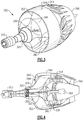
- Figure 3 schematically illustrates an isometric view of an example aft fan gas turbine engine 300 according to one embodiment.
- Figure 4 schematically illustrates a cross sectional view of the aft fan gas turbine engine 300 of Figure 3 , along an axis defined by a turbine motor 320.
- a gas generator 310 is positioned fore of the turbine motor 320, and provides pressurized gas to the turbine motor 320.
- the turbine motor 320 is connected to a fan 330 via a shaft 322.
- the gas generator 310 is a two spool gas generator. In alternative examples, alternative gas generator types may be utilized to the same effect.
- a fan duct 340 includes an inlet 342, and is defined by an inner duct wall 344 and the outer fairing 346.
- the fan duct 340 further includes an outlet 348 that expels air aft of the fan 330.
- the inner duct wall 344 includes an interface flange that interfaces the aft fan engine 300 with the fuselage of the aircraft on which the aft fan engine 300 is mounted, and maintains the engine 300 in position relative to the fuselage.
- a turbine exhaust duct 350 that connects an exhaust outlet 324 from the turbine motor 320 to the fan duct outlet 348.
- the exhaust gasses from the turbine motor 320, and the air from the fan duct 340 are mixed and expelled simultaneously.
- the exhaust ducts 350 pass through the fan duct 340 through multiple struts 352, and proceed through the radially outward fan ducting 354 to the outlet 348.
- an electrical generator 360 can be further connected to the shaft 322, and generate electrical energy via rotation of the shaft 322.
- the electrical generator 360 is directly connected to the shaft 322.
- the electrical generator 360 is connected to the shaft via a clutch, and can be geared to rotate at a different speed than the shaft 322. While illustrated herein as being positioned aft of the fan 330, one of skill in the art will appreciate that, in alternate examples, the electrical generator 360 can be positioned at any position along the shaft 322 and is not limited to being positioned aft of the fan 330.
- the electrical generator 360 is sized to absorb power from the fan 330, and prevent the fan 330 from windmilling during takeoff and landing, or during any other mode of operations.
- electrical energy can be actively supplied to the electrical generator 360 from a power source applying rotational force opposite a direction of windmilling, or the natural resistance to rotation of the electrical generator 360 can prevent rotation of the fan 330, depending on the specific configuration of the electrical generator 360 being utilized and of the aft fan engine.
- the gas generator 310 need not be in line with the turbine motor 320.
- the gas generator 310 can be angled, relative to an axis defined by the turbine motor 320, and shifted radially, relative to the axis, within the fuselage of the aircraft. This angling and shifting allows an area surrounding the gas generator 310 susceptible to burst damage during a catastrophic failure of the gas generator 310 to be controlled, and prevents the area from intersecting with any vital elements of the aft fan engine 300, or any other essential operational elements of the aircraft. This area is referred to as the "burst zone".
- Figure 5 schematically illustrates a connection of an aft fan engine 400 to a tail section 450 of an aircraft.
- the tail section includes a vertical tail stabilizer 452, and an aft fuselage bulkhead 454 below the vertical stabilizer 452.
- a flange 402 of the aft fan engine 400 interfaces with the aft fuselage bulkhead 454 via any known interfacing or mounting system.
- the flange 402 forms the radial internal surface of a boundary layer ingestion inlet 404. Due to the position of the boundary layer ingestion inlet 404, a boundary layer immediately adjacent the surface of the fuselage 456 is ingested into the fan duct, and driven through the aft fan engine via a fan 406.
- the aft fan engine 400 can be connected to, and operate on, existing aircraft without requiring substantial modification of the existing aircraft architecture. In doing so, the existing aircraft can recognize the benefit of an energized boundary layer through increased efficiency of the primary engines, and through decreased thrust requirements during operation.
- Figure 6 illustrates the engine 400 of Figure 5 connected to the tail section 450, with a fairing 460 removed for illustrative purposes.
- Interior to the fairing 460 is a ducting system 470.
- the ducting system 470 protrudes through structural struts 458 and is connected to an exhaust from the turbine motor 320 (See Figure 3 ).
- Each exhaust duct in the ducting system 470 is connected to multiple exhaust mixers 472 positioned aft of the fan 406.
- the exhaust mixers 472 direct a portion of exhaust from the corresponding exhaust duct 470 into a fanstream aft of the fan 406, where the exhaust is mixed with the ingested boundary layer air, and subsequently expelled from the aft fan engine 400.
- Figure 7 schematically illustrates the connection between the ducting 470 and the exhaust mixers 472 in a closer view.
- the ducting system 470 includes multiple primary ducts 474, each of which splits into multiple branches 476.
- Each of the branches 476 connects with a corresponding exhaust mixer 472, which injects the exhaust gasses into the primary flowpath of the aft fan engine 400.
- the exhaust mixers 472 are distributed evenly about the circumference of the aft fan engine 400.
- the spacing can be uneven, depending on the specific desired characteristics of the exhaust mixing.
- the ducting 470 can be directed through fan exit guide vanes, or other non-structural turning vanes in the fanstream.
- the described aft fan turbine engine can be utilized in alternative environments, such as a marine environment, where fluids other than air are driven through the fan.
- the boundary layer ingested by the fan is comprised of the ambient fluid of the environment.
Landscapes
- Engineering & Computer Science (AREA)
- Chemical & Material Sciences (AREA)
- Combustion & Propulsion (AREA)
- Mechanical Engineering (AREA)
- General Engineering & Computer Science (AREA)
- Aviation & Aerospace Engineering (AREA)
- Structures Of Non-Positive Displacement Pumps (AREA)
Applications Claiming Priority (1)
| Application Number | Priority Date | Filing Date | Title |
|---|---|---|---|
| US15/371,589 US10823056B2 (en) | 2016-12-07 | 2016-12-07 | Boundary layer excitation aft fan gas turbine engine |
Publications (2)
| Publication Number | Publication Date |
|---|---|
| EP3333403A1 true EP3333403A1 (de) | 2018-06-13 |
| EP3333403B1 EP3333403B1 (de) | 2021-10-13 |
Family
ID=60654745
Family Applications (1)
| Application Number | Title | Priority Date | Filing Date |
|---|---|---|---|
| EP17206030.3A Not-in-force EP3333403B1 (de) | 2016-12-07 | 2017-12-07 | Aft-fan-gasturbine zur grenzschichtanregung |
Country Status (2)
| Country | Link |
|---|---|
| US (1) | US10823056B2 (de) |
| EP (1) | EP3333403B1 (de) |
Cited By (3)
| Publication number | Priority date | Publication date | Assignee | Title |
|---|---|---|---|---|
| EP3666644A1 (de) * | 2018-12-13 | 2020-06-17 | United Technologies Corporation | System zur förderung von beschleunigter grenzschichtaufnahme |
| US11338901B2 (en) | 2019-04-26 | 2022-05-24 | Rolls-Royce Corporation | Nacelle for a boundary layer ingestion propulsor |
| EP3351475B1 (de) * | 2017-01-20 | 2023-12-13 | General Electric Company | Triebwerksgondel für ein hecktriebwerk eines luftfahrzeugs |
Families Citing this family (12)
| Publication number | Priority date | Publication date | Assignee | Title |
|---|---|---|---|---|
| US10000293B2 (en) | 2015-01-23 | 2018-06-19 | General Electric Company | Gas-electric propulsion system for an aircraft |
| US10676205B2 (en) | 2016-08-19 | 2020-06-09 | General Electric Company | Propulsion engine for an aircraft |
| US10538335B2 (en) * | 2016-12-19 | 2020-01-21 | The Boeing Company | Boundary layer ingestion integration into aft fuselage |
| GB201702822D0 (en) * | 2017-02-22 | 2017-04-05 | Rolls Royce Plc | A propulsor |
| US11111029B2 (en) * | 2017-07-28 | 2021-09-07 | The Boeing Company | System and method for operating a boundary layer ingestion fan |
| US10906657B2 (en) * | 2018-06-19 | 2021-02-02 | Raytheon Technologies Corporation | Aircraft system with distributed propulsion |
| US10759545B2 (en) | 2018-06-19 | 2020-09-01 | Raytheon Technologies Corporation | Hybrid electric aircraft system with distributed propulsion |
| FR3099138B1 (fr) * | 2019-07-23 | 2021-07-02 | Safran Aircraft Engines | Aéronef comportant un propulseur à soufflante à l’arrière du fuselage et une structure d’accrochage de ce propulseur |
| US12187443B2 (en) * | 2020-02-14 | 2025-01-07 | Bombardier Inc. | Excess thrust control for an aircraft |
| US20210403168A1 (en) * | 2020-06-29 | 2021-12-30 | Bell Textron Inc. | Hybrid propulsion system for convertible aircraft |
| CA3257133A1 (en) * | 2022-05-13 | 2023-11-16 | Firestorm Labs, Inc. | MISSION-ADAPABLE AIR VEHICLE AND FIELD ASSEMBLY AND OPERATION PROCESSES |
| US12246844B1 (en) | 2023-11-29 | 2025-03-11 | Pratt & Whitney Canada Corp. | Hybrid aircraft power plant |
Citations (5)
| Publication number | Priority date | Publication date | Assignee | Title |
|---|---|---|---|---|
| FR1443200A (fr) * | 1965-04-21 | 1966-06-24 | Bristol Siddeley Engines Ltd | Groupe propulseur utilisant une turbine à gaz, pour aéronefs |
| GB1211081A (en) * | 1967-05-19 | 1970-11-04 | Rolls Royce | Jet propelled aircraft |
| EP2204567A2 (de) * | 2008-12-31 | 2010-07-07 | Rolls-Royce Corporation | Gasturbinentriebwerk mit Ejektor und zugehöriges Betriebsverfahren |
| US20100186418A1 (en) * | 2009-01-23 | 2010-07-29 | Snecma | Turbine engine with a power turbine equipped with an electric power generator centered on the axis of the turbine engine |
| US20150291285A1 (en) * | 2012-11-08 | 2015-10-15 | Snecma | Aircraft propelled by a turbojet engine with contrarotating fans |
Family Cites Families (16)
| Publication number | Priority date | Publication date | Assignee | Title |
|---|---|---|---|---|
| US3348379A (en) | 1963-09-25 | 1967-10-24 | Rolls Royce | Turbojet engine with compressor bypass and aft fan |
| US3332242A (en) | 1965-03-31 | 1967-07-25 | Gen Motors Corp | Aft fan jet engine |
| US5161369A (en) | 1991-01-28 | 1992-11-10 | Williams International Corporation | Aft fan gas turbine engine |
| US7631484B2 (en) | 2006-03-13 | 2009-12-15 | Rollin George Giffin | High pressure ratio aft fan |
| JP4788966B2 (ja) | 2006-09-27 | 2011-10-05 | 独立行政法人 宇宙航空研究開発機構 | ターボファンジェットエンジン |
| US7752834B2 (en) * | 2006-10-25 | 2010-07-13 | United Technologies Corporation | Aircraft propulsion systems |
| DE102008060488A1 (de) | 2008-12-05 | 2010-06-10 | Rolls-Royce Deutschland Ltd & Co Kg | Verfahren und Vorrichtung zum Betrieb eines mit Schubpropellern versehenen Turboprop-Flugtriebwerkes |
| US9016041B2 (en) | 2010-11-30 | 2015-04-28 | General Electric Company | Variable-cycle gas turbine engine with front and aft FLADE stages |
| US8516789B2 (en) | 2011-07-26 | 2013-08-27 | United Technologies Corporation | Gas turbine engine with aft core driven fan section |
| US9297270B2 (en) | 2012-02-29 | 2016-03-29 | United Technologies Corporation | Gas turbine engine driving multiple fans |
| CA2913771A1 (en) * | 2014-12-15 | 2016-06-15 | Rolls-Royce Corporation | Aircraft boundary layer removal with auxilliary power unit suction |
| FR3039133B1 (fr) * | 2015-07-22 | 2020-01-17 | Safran Aircraft Engines | Aeronef avec un ensemble propulsif comprenant une soufflante a l'arriere du fuselage |
| US9957055B2 (en) * | 2015-09-21 | 2018-05-01 | General Electric Company | Aft engine for an aircraft |
| US10392120B2 (en) * | 2016-04-19 | 2019-08-27 | General Electric Company | Propulsion engine for an aircraft |
| US10287024B2 (en) | 2016-08-04 | 2019-05-14 | United Technologies Corporation | Direct drive aft fan engine |
| US10737801B2 (en) * | 2016-10-31 | 2020-08-11 | Rolls-Royce Corporation | Fan module with rotatable vane ring power system |
-
2016
- 2016-12-07 US US15/371,589 patent/US10823056B2/en not_active Expired - Fee Related
-
2017
- 2017-12-07 EP EP17206030.3A patent/EP3333403B1/de not_active Not-in-force
Patent Citations (5)
| Publication number | Priority date | Publication date | Assignee | Title |
|---|---|---|---|---|
| FR1443200A (fr) * | 1965-04-21 | 1966-06-24 | Bristol Siddeley Engines Ltd | Groupe propulseur utilisant une turbine à gaz, pour aéronefs |
| GB1211081A (en) * | 1967-05-19 | 1970-11-04 | Rolls Royce | Jet propelled aircraft |
| EP2204567A2 (de) * | 2008-12-31 | 2010-07-07 | Rolls-Royce Corporation | Gasturbinentriebwerk mit Ejektor und zugehöriges Betriebsverfahren |
| US20100186418A1 (en) * | 2009-01-23 | 2010-07-29 | Snecma | Turbine engine with a power turbine equipped with an electric power generator centered on the axis of the turbine engine |
| US20150291285A1 (en) * | 2012-11-08 | 2015-10-15 | Snecma | Aircraft propelled by a turbojet engine with contrarotating fans |
Cited By (4)
| Publication number | Priority date | Publication date | Assignee | Title |
|---|---|---|---|---|
| EP3351475B1 (de) * | 2017-01-20 | 2023-12-13 | General Electric Company | Triebwerksgondel für ein hecktriebwerk eines luftfahrzeugs |
| EP3666644A1 (de) * | 2018-12-13 | 2020-06-17 | United Technologies Corporation | System zur förderung von beschleunigter grenzschichtaufnahme |
| US11124291B2 (en) | 2018-12-13 | 2021-09-21 | Raytheon Technologies Corporation | System to promote accelerated boundary layer ingestion |
| US11338901B2 (en) | 2019-04-26 | 2022-05-24 | Rolls-Royce Corporation | Nacelle for a boundary layer ingestion propulsor |
Also Published As
| Publication number | Publication date |
|---|---|
| US20180156109A1 (en) | 2018-06-07 |
| US10823056B2 (en) | 2020-11-03 |
| EP3333403B1 (de) | 2021-10-13 |
Similar Documents
| Publication | Publication Date | Title |
|---|---|---|
| EP3333403B1 (de) | Aft-fan-gasturbine zur grenzschichtanregung | |
| US7752834B2 (en) | Aircraft propulsion systems | |
| US8955335B2 (en) | System, propulsion system and vehicle | |
| EP1918199B1 (de) | Auslegung eines Flugzeugs | |
| US9726112B2 (en) | Reverse flow gas turbine engine airflow bypass | |
| US20160355272A1 (en) | Aircraft propulsion system | |
| EP3943733B1 (de) | Systeme und verfahren für gasturbinenmotoren | |
| EP3284942B1 (de) | Fantriebwerk mit hinten angeordneten und direkt angetriebenen fan | |
| EP2719619B1 (de) | Drehflügelflugzeug mit ineinander angeordnetem Abgaskanal und Propellerwelle | |
| US10830129B2 (en) | Transverse-mounted power turbine drive system | |
| US9644537B2 (en) | Free stream intake with particle separator for reverse core engine | |
| CN107161349A (zh) | 用于飞机的推进系统 | |
| EP4283162A1 (de) | Selektive leistungsverteilung für ein flugzeugantriebssystem | |
| CA2951800C (en) | Method and system for in-line distributed propulsion | |
| EP3557036B1 (de) | Gegenläufiger grenzschichtaufnahmeheckmotor | |
| EP4283109A1 (de) | Schubvektorisierungsabgasdüse für ein flugzeugantriebssystem | |
| US20170057649A1 (en) | Integrated aircraft propulsion system | |
| US3262659A (en) | Thrust control apparatus | |
| US12158112B1 (en) | Selective power distribution for an aircraft propulsion system |
Legal Events
| Date | Code | Title | Description |
|---|---|---|---|
| PUAI | Public reference made under article 153(3) epc to a published international application that has entered the european phase |
Free format text: ORIGINAL CODE: 0009012 |
|
| STAA | Information on the status of an ep patent application or granted ep patent |
Free format text: STATUS: THE APPLICATION HAS BEEN PUBLISHED |
|
| AK | Designated contracting states |
Kind code of ref document: A1 Designated state(s): AL AT BE BG CH CY CZ DE DK EE ES FI FR GB GR HR HU IE IS IT LI LT LU LV MC MK MT NL NO PL PT RO RS SE SI SK SM TR |
|
| AX | Request for extension of the european patent |
Extension state: BA ME |
|
| STAA | Information on the status of an ep patent application or granted ep patent |
Free format text: STATUS: REQUEST FOR EXAMINATION WAS MADE |
|
| 17P | Request for examination filed |
Effective date: 20181213 |
|
| RBV | Designated contracting states (corrected) |
Designated state(s): AL AT BE BG CH CY CZ DE DK EE ES FI FR GB GR HR HU IE IS IT LI LT LU LV MC MK MT NL NO PL PT RO RS SE SI SK SM TR |
|
| STAA | Information on the status of an ep patent application or granted ep patent |
Free format text: STATUS: EXAMINATION IS IN PROGRESS |
|
| 17Q | First examination report despatched |
Effective date: 20200804 |
|
| RAP1 | Party data changed (applicant data changed or rights of an application transferred) |
Owner name: RAYTHEON TECHNOLOGIES CORPORATION |
|
| GRAP | Despatch of communication of intention to grant a patent |
Free format text: ORIGINAL CODE: EPIDOSNIGR1 |
|
| STAA | Information on the status of an ep patent application or granted ep patent |
Free format text: STATUS: GRANT OF PATENT IS INTENDED |
|
| INTG | Intention to grant announced |
Effective date: 20210428 |
|
| GRAS | Grant fee paid |
Free format text: ORIGINAL CODE: EPIDOSNIGR3 |
|
| GRAA | (expected) grant |
Free format text: ORIGINAL CODE: 0009210 |
|
| STAA | Information on the status of an ep patent application or granted ep patent |
Free format text: STATUS: THE PATENT HAS BEEN GRANTED |
|
| AK | Designated contracting states |
Kind code of ref document: B1 Designated state(s): AL AT BE BG CH CY CZ DE DK EE ES FI FR GB GR HR HU IE IS IT LI LT LU LV MC MK MT NL NO PL PT RO RS SE SI SK SM TR |
|
| REG | Reference to a national code |
Ref country code: GB Ref legal event code: FG4D |
|
| REG | Reference to a national code |
Ref country code: CH Ref legal event code: EP |
|
| REG | Reference to a national code |
Ref country code: DE Ref legal event code: R096 Ref document number: 602017047488 Country of ref document: DE |
|
| REG | Reference to a national code |
Ref country code: IE Ref legal event code: FG4D |
|
| REG | Reference to a national code |
Ref country code: AT Ref legal event code: REF Ref document number: 1438367 Country of ref document: AT Kind code of ref document: T Effective date: 20211115 |
|
| REG | Reference to a national code |
Ref country code: LT Ref legal event code: MG9D |
|
| REG | Reference to a national code |
Ref country code: NL Ref legal event code: MP Effective date: 20211013 |
|
| REG | Reference to a national code |
Ref country code: AT Ref legal event code: MK05 Ref document number: 1438367 Country of ref document: AT Kind code of ref document: T Effective date: 20211013 |
|
| PG25 | Lapsed in a contracting state [announced via postgrant information from national office to epo] |
Ref country code: RS Free format text: LAPSE BECAUSE OF FAILURE TO SUBMIT A TRANSLATION OF THE DESCRIPTION OR TO PAY THE FEE WITHIN THE PRESCRIBED TIME-LIMIT Effective date: 20211013 Ref country code: LT Free format text: LAPSE BECAUSE OF FAILURE TO SUBMIT A TRANSLATION OF THE DESCRIPTION OR TO PAY THE FEE WITHIN THE PRESCRIBED TIME-LIMIT Effective date: 20211013 Ref country code: FI Free format text: LAPSE BECAUSE OF FAILURE TO SUBMIT A TRANSLATION OF THE DESCRIPTION OR TO PAY THE FEE WITHIN THE PRESCRIBED TIME-LIMIT Effective date: 20211013 Ref country code: BG Free format text: LAPSE BECAUSE OF FAILURE TO SUBMIT A TRANSLATION OF THE DESCRIPTION OR TO PAY THE FEE WITHIN THE PRESCRIBED TIME-LIMIT Effective date: 20220113 Ref country code: AT Free format text: LAPSE BECAUSE OF FAILURE TO SUBMIT A TRANSLATION OF THE DESCRIPTION OR TO PAY THE FEE WITHIN THE PRESCRIBED TIME-LIMIT Effective date: 20211013 |
|
| PG25 | Lapsed in a contracting state [announced via postgrant information from national office to epo] |
Ref country code: IS Free format text: LAPSE BECAUSE OF FAILURE TO SUBMIT A TRANSLATION OF THE DESCRIPTION OR TO PAY THE FEE WITHIN THE PRESCRIBED TIME-LIMIT Effective date: 20220213 Ref country code: SE Free format text: LAPSE BECAUSE OF FAILURE TO SUBMIT A TRANSLATION OF THE DESCRIPTION OR TO PAY THE FEE WITHIN THE PRESCRIBED TIME-LIMIT Effective date: 20211013 Ref country code: PT Free format text: LAPSE BECAUSE OF FAILURE TO SUBMIT A TRANSLATION OF THE DESCRIPTION OR TO PAY THE FEE WITHIN THE PRESCRIBED TIME-LIMIT Effective date: 20220214 Ref country code: PL Free format text: LAPSE BECAUSE OF FAILURE TO SUBMIT A TRANSLATION OF THE DESCRIPTION OR TO PAY THE FEE WITHIN THE PRESCRIBED TIME-LIMIT Effective date: 20211013 Ref country code: NO Free format text: LAPSE BECAUSE OF FAILURE TO SUBMIT A TRANSLATION OF THE DESCRIPTION OR TO PAY THE FEE WITHIN THE PRESCRIBED TIME-LIMIT Effective date: 20220113 Ref country code: NL Free format text: LAPSE BECAUSE OF FAILURE TO SUBMIT A TRANSLATION OF THE DESCRIPTION OR TO PAY THE FEE WITHIN THE PRESCRIBED TIME-LIMIT Effective date: 20211013 Ref country code: LV Free format text: LAPSE BECAUSE OF FAILURE TO SUBMIT A TRANSLATION OF THE DESCRIPTION OR TO PAY THE FEE WITHIN THE PRESCRIBED TIME-LIMIT Effective date: 20211013 Ref country code: HR Free format text: LAPSE BECAUSE OF FAILURE TO SUBMIT A TRANSLATION OF THE DESCRIPTION OR TO PAY THE FEE WITHIN THE PRESCRIBED TIME-LIMIT Effective date: 20211013 Ref country code: GR Free format text: LAPSE BECAUSE OF FAILURE TO SUBMIT A TRANSLATION OF THE DESCRIPTION OR TO PAY THE FEE WITHIN THE PRESCRIBED TIME-LIMIT Effective date: 20220114 Ref country code: ES Free format text: LAPSE BECAUSE OF FAILURE TO SUBMIT A TRANSLATION OF THE DESCRIPTION OR TO PAY THE FEE WITHIN THE PRESCRIBED TIME-LIMIT Effective date: 20211013 |
|
| REG | Reference to a national code |
Ref country code: DE Ref legal event code: R097 Ref document number: 602017047488 Country of ref document: DE |
|
| PG25 | Lapsed in a contracting state [announced via postgrant information from national office to epo] |
Ref country code: SM Free format text: LAPSE BECAUSE OF FAILURE TO SUBMIT A TRANSLATION OF THE DESCRIPTION OR TO PAY THE FEE WITHIN THE PRESCRIBED TIME-LIMIT Effective date: 20211013 Ref country code: SK Free format text: LAPSE BECAUSE OF FAILURE TO SUBMIT A TRANSLATION OF THE DESCRIPTION OR TO PAY THE FEE WITHIN THE PRESCRIBED TIME-LIMIT Effective date: 20211013 Ref country code: RO Free format text: LAPSE BECAUSE OF FAILURE TO SUBMIT A TRANSLATION OF THE DESCRIPTION OR TO PAY THE FEE WITHIN THE PRESCRIBED TIME-LIMIT Effective date: 20211013 Ref country code: MC Free format text: LAPSE BECAUSE OF FAILURE TO SUBMIT A TRANSLATION OF THE DESCRIPTION OR TO PAY THE FEE WITHIN THE PRESCRIBED TIME-LIMIT Effective date: 20211013 Ref country code: EE Free format text: LAPSE BECAUSE OF FAILURE TO SUBMIT A TRANSLATION OF THE DESCRIPTION OR TO PAY THE FEE WITHIN THE PRESCRIBED TIME-LIMIT Effective date: 20211013 Ref country code: DK Free format text: LAPSE BECAUSE OF FAILURE TO SUBMIT A TRANSLATION OF THE DESCRIPTION OR TO PAY THE FEE WITHIN THE PRESCRIBED TIME-LIMIT Effective date: 20211013 Ref country code: CZ Free format text: LAPSE BECAUSE OF FAILURE TO SUBMIT A TRANSLATION OF THE DESCRIPTION OR TO PAY THE FEE WITHIN THE PRESCRIBED TIME-LIMIT Effective date: 20211013 |
|
| REG | Reference to a national code |
Ref country code: CH Ref legal event code: PL |
|
| PLBE | No opposition filed within time limit |
Free format text: ORIGINAL CODE: 0009261 |
|
| STAA | Information on the status of an ep patent application or granted ep patent |
Free format text: STATUS: NO OPPOSITION FILED WITHIN TIME LIMIT |
|
| 26N | No opposition filed |
Effective date: 20220714 |
|
| REG | Reference to a national code |
Ref country code: BE Ref legal event code: MM Effective date: 20211231 |
|
| PG25 | Lapsed in a contracting state [announced via postgrant information from national office to epo] |
Ref country code: LU Free format text: LAPSE BECAUSE OF NON-PAYMENT OF DUE FEES Effective date: 20211207 Ref country code: IE Free format text: LAPSE BECAUSE OF NON-PAYMENT OF DUE FEES Effective date: 20211207 Ref country code: AL Free format text: LAPSE BECAUSE OF FAILURE TO SUBMIT A TRANSLATION OF THE DESCRIPTION OR TO PAY THE FEE WITHIN THE PRESCRIBED TIME-LIMIT Effective date: 20211013 |
|
| PG25 | Lapsed in a contracting state [announced via postgrant information from national office to epo] |
Ref country code: SI Free format text: LAPSE BECAUSE OF FAILURE TO SUBMIT A TRANSLATION OF THE DESCRIPTION OR TO PAY THE FEE WITHIN THE PRESCRIBED TIME-LIMIT Effective date: 20211013 Ref country code: BE Free format text: LAPSE BECAUSE OF NON-PAYMENT OF DUE FEES Effective date: 20211231 |
|
| PG25 | Lapsed in a contracting state [announced via postgrant information from national office to epo] |
Ref country code: LI Free format text: LAPSE BECAUSE OF NON-PAYMENT OF DUE FEES Effective date: 20211231 Ref country code: CH Free format text: LAPSE BECAUSE OF NON-PAYMENT OF DUE FEES Effective date: 20211231 |
|
| PGFP | Annual fee paid to national office [announced via postgrant information from national office to epo] |
Ref country code: GB Payment date: 20221116 Year of fee payment: 6 Ref country code: FR Payment date: 20221122 Year of fee payment: 6 Ref country code: DE Payment date: 20220616 Year of fee payment: 6 |
|
| PG25 | Lapsed in a contracting state [announced via postgrant information from national office to epo] |
Ref country code: IT Free format text: LAPSE BECAUSE OF FAILURE TO SUBMIT A TRANSLATION OF THE DESCRIPTION OR TO PAY THE FEE WITHIN THE PRESCRIBED TIME-LIMIT Effective date: 20211013 Ref country code: HU Free format text: LAPSE BECAUSE OF FAILURE TO SUBMIT A TRANSLATION OF THE DESCRIPTION OR TO PAY THE FEE WITHIN THE PRESCRIBED TIME-LIMIT; INVALID AB INITIO Effective date: 20171207 |
|
| P01 | Opt-out of the competence of the unified patent court (upc) registered |
Effective date: 20230520 |
|
| PG25 | Lapsed in a contracting state [announced via postgrant information from national office to epo] |
Ref country code: CY Free format text: LAPSE BECAUSE OF FAILURE TO SUBMIT A TRANSLATION OF THE DESCRIPTION OR TO PAY THE FEE WITHIN THE PRESCRIBED TIME-LIMIT Effective date: 20211013 |
|
| PG25 | Lapsed in a contracting state [announced via postgrant information from national office to epo] |
Ref country code: MK Free format text: LAPSE BECAUSE OF FAILURE TO SUBMIT A TRANSLATION OF THE DESCRIPTION OR TO PAY THE FEE WITHIN THE PRESCRIBED TIME-LIMIT Effective date: 20211013 |
|
| PG25 | Lapsed in a contracting state [announced via postgrant information from national office to epo] |
Ref country code: TR Free format text: LAPSE BECAUSE OF FAILURE TO SUBMIT A TRANSLATION OF THE DESCRIPTION OR TO PAY THE FEE WITHIN THE PRESCRIBED TIME-LIMIT Effective date: 20211013 |
|
| REG | Reference to a national code |
Ref country code: DE Ref legal event code: R119 Ref document number: 602017047488 Country of ref document: DE |
|
| GBPC | Gb: european patent ceased through non-payment of renewal fee |
Effective date: 20231207 |
|
| PG25 | Lapsed in a contracting state [announced via postgrant information from national office to epo] |
Ref country code: MT Free format text: LAPSE BECAUSE OF FAILURE TO SUBMIT A TRANSLATION OF THE DESCRIPTION OR TO PAY THE FEE WITHIN THE PRESCRIBED TIME-LIMIT Effective date: 20211013 |
|
| PG25 | Lapsed in a contracting state [announced via postgrant information from national office to epo] |
Ref country code: DE Free format text: LAPSE BECAUSE OF NON-PAYMENT OF DUE FEES Effective date: 20240702 |
|
| PG25 | Lapsed in a contracting state [announced via postgrant information from national office to epo] |
Ref country code: GB Free format text: LAPSE BECAUSE OF NON-PAYMENT OF DUE FEES Effective date: 20231207 |
|
| PG25 | Lapsed in a contracting state [announced via postgrant information from national office to epo] |
Ref country code: FR Free format text: LAPSE BECAUSE OF NON-PAYMENT OF DUE FEES Effective date: 20231231 |
|
| PG25 | Lapsed in a contracting state [announced via postgrant information from national office to epo] |
Ref country code: GB Free format text: LAPSE BECAUSE OF NON-PAYMENT OF DUE FEES Effective date: 20231207 Ref country code: FR Free format text: LAPSE BECAUSE OF NON-PAYMENT OF DUE FEES Effective date: 20231231 Ref country code: DE Free format text: LAPSE BECAUSE OF NON-PAYMENT OF DUE FEES Effective date: 20240702 |