EP3333367B1 - Generativ gefertigte dichtung für kammerbildung an einem einsatz in einer turbinenkomponente - Google Patents
Generativ gefertigte dichtung für kammerbildung an einem einsatz in einer turbinenkomponente Download PDFInfo
- Publication number
- EP3333367B1 EP3333367B1 EP17204881.1A EP17204881A EP3333367B1 EP 3333367 B1 EP3333367 B1 EP 3333367B1 EP 17204881 A EP17204881 A EP 17204881A EP 3333367 B1 EP3333367 B1 EP 3333367B1
- Authority
- EP
- European Patent Office
- Prior art keywords
- wall
- insert
- seal
- component
- interior space
- Prior art date
- Legal status (The legal status is an assumption and is not a legal conclusion. Google has not performed a legal analysis and makes no representation as to the accuracy of the status listed.)
- Active
Links
Images


Classifications
-
- F—MECHANICAL ENGINEERING; LIGHTING; HEATING; WEAPONS; BLASTING
- F01—MACHINES OR ENGINES IN GENERAL; ENGINE PLANTS IN GENERAL; STEAM ENGINES
- F01D—NON-POSITIVE DISPLACEMENT MACHINES OR ENGINES, e.g. STEAM TURBINES
- F01D11/00—Preventing or minimising internal leakage of working-fluid, e.g. between stages
- F01D11/003—Preventing or minimising internal leakage of working-fluid, e.g. between stages by packing rings; Mechanical seals
-
- B—PERFORMING OPERATIONS; TRANSPORTING
- B22—CASTING; POWDER METALLURGY
- B22F—WORKING METALLIC POWDER; MANUFACTURE OF ARTICLES FROM METALLIC POWDER; MAKING METALLIC POWDER; APPARATUS OR DEVICES SPECIALLY ADAPTED FOR METALLIC POWDER
- B22F5/00—Manufacture of workpieces or articles from metallic powder characterised by the special shape of the product
- B22F5/009—Manufacture of workpieces or articles from metallic powder characterised by the special shape of the product of turbine components other than turbine blades
-
- B—PERFORMING OPERATIONS; TRANSPORTING
- B22—CASTING; POWDER METALLURGY
- B22F—WORKING METALLIC POWDER; MANUFACTURE OF ARTICLES FROM METALLIC POWDER; MAKING METALLIC POWDER; APPARATUS OR DEVICES SPECIALLY ADAPTED FOR METALLIC POWDER
- B22F5/00—Manufacture of workpieces or articles from metallic powder characterised by the special shape of the product
- B22F5/04—Manufacture of workpieces or articles from metallic powder characterised by the special shape of the product of turbine blades
-
- B—PERFORMING OPERATIONS; TRANSPORTING
- B33—ADDITIVE MANUFACTURING TECHNOLOGY
- B33Y—ADDITIVE MANUFACTURING, i.e. MANUFACTURING OF THREE-DIMENSIONAL [3D] OBJECTS BY ADDITIVE DEPOSITION, ADDITIVE AGGLOMERATION OR ADDITIVE LAYERING, e.g. BY 3D PRINTING, STEREOLITHOGRAPHY OR SELECTIVE LASER SINTERING
- B33Y80/00—Products made by additive manufacturing
-
- F—MECHANICAL ENGINEERING; LIGHTING; HEATING; WEAPONS; BLASTING
- F01—MACHINES OR ENGINES IN GENERAL; ENGINE PLANTS IN GENERAL; STEAM ENGINES
- F01D—NON-POSITIVE DISPLACEMENT MACHINES OR ENGINES, e.g. STEAM TURBINES
- F01D25/00—Component parts, details, or accessories, not provided for in, or of interest apart from, other groups
- F01D25/08—Cooling; Heating; Heat-insulation
- F01D25/12—Cooling
-
- F—MECHANICAL ENGINEERING; LIGHTING; HEATING; WEAPONS; BLASTING
- F01—MACHINES OR ENGINES IN GENERAL; ENGINE PLANTS IN GENERAL; STEAM ENGINES
- F01D—NON-POSITIVE DISPLACEMENT MACHINES OR ENGINES, e.g. STEAM TURBINES
- F01D5/00—Blades; Blade-carrying members; Heating, heat-insulating, cooling or antivibration means on the blades or the members
- F01D5/12—Blades
- F01D5/14—Form or construction
- F01D5/18—Hollow blades, i.e. blades with cooling or heating channels or cavities; Heating, heat-insulating or cooling means on blades
- F01D5/187—Convection cooling
- F01D5/188—Convection cooling with an insert in the blade cavity to guide the cooling fluid, e.g. forming a separation wall
- F01D5/189—Convection cooling with an insert in the blade cavity to guide the cooling fluid, e.g. forming a separation wall the insert having a tubular cross-section, e.g. airfoil shape
-
- F—MECHANICAL ENGINEERING; LIGHTING; HEATING; WEAPONS; BLASTING
- F01—MACHINES OR ENGINES IN GENERAL; ENGINE PLANTS IN GENERAL; STEAM ENGINES
- F01D—NON-POSITIVE DISPLACEMENT MACHINES OR ENGINES, e.g. STEAM TURBINES
- F01D9/00—Stators
- F01D9/02—Nozzles; Nozzle boxes; Stator blades; Guide conduits, e.g. individual nozzles
-
- F—MECHANICAL ENGINEERING; LIGHTING; HEATING; WEAPONS; BLASTING
- F16—ENGINEERING ELEMENTS AND UNITS; GENERAL MEASURES FOR PRODUCING AND MAINTAINING EFFECTIVE FUNCTIONING OF MACHINES OR INSTALLATIONS; THERMAL INSULATION IN GENERAL
- F16J—PISTONS; CYLINDERS; SEALINGS
- F16J15/00—Sealings
- F16J15/02—Sealings between relatively-stationary surfaces
- F16J15/06—Sealings between relatively-stationary surfaces with solid packing compressed between sealing surfaces
- F16J15/08—Sealings between relatively-stationary surfaces with solid packing compressed between sealing surfaces with exclusively metal packing
- F16J15/0887—Sealings between relatively-stationary surfaces with solid packing compressed between sealing surfaces with exclusively metal packing the sealing effect being obtained by elastic deformation of the packing
- F16J15/0893—Sealings between relatively-stationary surfaces with solid packing compressed between sealing surfaces with exclusively metal packing the sealing effect being obtained by elastic deformation of the packing the packing having a hollow profile
-
- B—PERFORMING OPERATIONS; TRANSPORTING
- B22—CASTING; POWDER METALLURGY
- B22F—WORKING METALLIC POWDER; MANUFACTURE OF ARTICLES FROM METALLIC POWDER; MAKING METALLIC POWDER; APPARATUS OR DEVICES SPECIALLY ADAPTED FOR METALLIC POWDER
- B22F10/00—Additive manufacturing of workpieces or articles from metallic powder
- B22F10/20—Direct sintering or melting
- B22F10/28—Powder bed fusion, e.g. selective laser melting [SLM] or electron beam melting [EBM]
-
- F—MECHANICAL ENGINEERING; LIGHTING; HEATING; WEAPONS; BLASTING
- F05—INDEXING SCHEMES RELATING TO ENGINES OR PUMPS IN VARIOUS SUBCLASSES OF CLASSES F01-F04
- F05D—INDEXING SCHEME FOR ASPECTS RELATING TO NON-POSITIVE-DISPLACEMENT MACHINES OR ENGINES, GAS-TURBINES OR JET-PROPULSION PLANTS
- F05D2220/00—Application
- F05D2220/30—Application in turbines
- F05D2220/32—Application in turbines in gas turbines
-
- F—MECHANICAL ENGINEERING; LIGHTING; HEATING; WEAPONS; BLASTING
- F05—INDEXING SCHEMES RELATING TO ENGINES OR PUMPS IN VARIOUS SUBCLASSES OF CLASSES F01-F04
- F05D—INDEXING SCHEME FOR ASPECTS RELATING TO NON-POSITIVE-DISPLACEMENT MACHINES OR ENGINES, GAS-TURBINES OR JET-PROPULSION PLANTS
- F05D2230/00—Manufacture
- F05D2230/20—Manufacture essentially without removing material
- F05D2230/22—Manufacture essentially without removing material by sintering
-
- F—MECHANICAL ENGINEERING; LIGHTING; HEATING; WEAPONS; BLASTING
- F05—INDEXING SCHEMES RELATING TO ENGINES OR PUMPS IN VARIOUS SUBCLASSES OF CLASSES F01-F04
- F05D—INDEXING SCHEME FOR ASPECTS RELATING TO NON-POSITIVE-DISPLACEMENT MACHINES OR ENGINES, GAS-TURBINES OR JET-PROPULSION PLANTS
- F05D2230/00—Manufacture
- F05D2230/20—Manufacture essentially without removing material
- F05D2230/23—Manufacture essentially without removing material by permanently joining parts together
- F05D2230/232—Manufacture essentially without removing material by permanently joining parts together by welding
- F05D2230/234—Laser welding
-
- F—MECHANICAL ENGINEERING; LIGHTING; HEATING; WEAPONS; BLASTING
- F05—INDEXING SCHEMES RELATING TO ENGINES OR PUMPS IN VARIOUS SUBCLASSES OF CLASSES F01-F04
- F05D—INDEXING SCHEME FOR ASPECTS RELATING TO NON-POSITIVE-DISPLACEMENT MACHINES OR ENGINES, GAS-TURBINES OR JET-PROPULSION PLANTS
- F05D2240/00—Components
- F05D2240/55—Seals
-
- F—MECHANICAL ENGINEERING; LIGHTING; HEATING; WEAPONS; BLASTING
- F05—INDEXING SCHEMES RELATING TO ENGINES OR PUMPS IN VARIOUS SUBCLASSES OF CLASSES F01-F04
- F05D—INDEXING SCHEME FOR ASPECTS RELATING TO NON-POSITIVE-DISPLACEMENT MACHINES OR ENGINES, GAS-TURBINES OR JET-PROPULSION PLANTS
- F05D2250/00—Geometry
- F05D2250/70—Shape
- F05D2250/75—Shape given by its similarity to a letter, e.g. T-shaped
-
- F—MECHANICAL ENGINEERING; LIGHTING; HEATING; WEAPONS; BLASTING
- F05—INDEXING SCHEMES RELATING TO ENGINES OR PUMPS IN VARIOUS SUBCLASSES OF CLASSES F01-F04
- F05D—INDEXING SCHEME FOR ASPECTS RELATING TO NON-POSITIVE-DISPLACEMENT MACHINES OR ENGINES, GAS-TURBINES OR JET-PROPULSION PLANTS
- F05D2260/00—Function
- F05D2260/20—Heat transfer, e.g. cooling
- F05D2260/201—Heat transfer, e.g. cooling by impingement of a fluid
-
- F—MECHANICAL ENGINEERING; LIGHTING; HEATING; WEAPONS; BLASTING
- F05—INDEXING SCHEMES RELATING TO ENGINES OR PUMPS IN VARIOUS SUBCLASSES OF CLASSES F01-F04
- F05D—INDEXING SCHEME FOR ASPECTS RELATING TO NON-POSITIVE-DISPLACEMENT MACHINES OR ENGINES, GAS-TURBINES OR JET-PROPULSION PLANTS
- F05D2260/00—Function
- F05D2260/30—Retaining components in desired mutual position
-
- Y—GENERAL TAGGING OF NEW TECHNOLOGICAL DEVELOPMENTS; GENERAL TAGGING OF CROSS-SECTIONAL TECHNOLOGIES SPANNING OVER SEVERAL SECTIONS OF THE IPC; TECHNICAL SUBJECTS COVERED BY FORMER USPC CROSS-REFERENCE ART COLLECTIONS [XRACs] AND DIGESTS
- Y02—TECHNOLOGIES OR APPLICATIONS FOR MITIGATION OR ADAPTATION AGAINST CLIMATE CHANGE
- Y02P—CLIMATE CHANGE MITIGATION TECHNOLOGIES IN THE PRODUCTION OR PROCESSING OF GOODS
- Y02P10/00—Technologies related to metal processing
- Y02P10/25—Process efficiency
-
- Y—GENERAL TAGGING OF NEW TECHNOLOGICAL DEVELOPMENTS; GENERAL TAGGING OF CROSS-SECTIONAL TECHNOLOGIES SPANNING OVER SEVERAL SECTIONS OF THE IPC; TECHNICAL SUBJECTS COVERED BY FORMER USPC CROSS-REFERENCE ART COLLECTIONS [XRACs] AND DIGESTS
- Y02—TECHNOLOGIES OR APPLICATIONS FOR MITIGATION OR ADAPTATION AGAINST CLIMATE CHANGE
- Y02T—CLIMATE CHANGE MITIGATION TECHNOLOGIES RELATED TO TRANSPORTATION
- Y02T50/00—Aeronautics or air transport
- Y02T50/60—Efficient propulsion technologies, e.g. for aircraft
Definitions
- the disclosure relates generally to turbine components and airfoil blades, such as vanes/nozzles in turbomachines. More particularly, embodiments of the present disclosure provide sealing inserts, turbine components, and code for making laser-sintered components for cooling hollow airfoils from the inside with directed fluid, such as air.
- manufacture of metallic components generally includes milling or cutting away regions from a slab of metal before treating and modifying the cut metal to yield a part, which may have been simulated using computer models and computer aided design.
- Manufactured components which may be formed from metal include airfoil components for installation in a turbomachine such as an aircraft engine or power generation system, as well as mechanical components for other manufacturing, transportation, and structural systems.
- US 8,556,578 B1 suggests a flexible seal having an X-shaped cross section that forms four contact points on four contact surfaces of two opposed seal slots.
- the flexible seal is used for a component in which the two seal slots undergo a large deflection such that the opposed slots are not aligned and a rigid seal will not form an adequate seal.
- the flexible seal can be used in a component of a combustor or a turbine in a gas turbine engine where opposed seal slots undergo the large deflection during operation.
- EP 1 852 572 A2 discloses a vane that has an airfoil shell and a spar within the shell.
- the vane has an outboard shroud at an outboard end of the shell and an inboard platform at an inboard end of the shell.
- the spar has a first chamber essentially along the suction side and a second chamber along the pressure side opposite the first chamber.
- EP 3 075 531 A1 suggests a sandwich arrangement that comprises at least two peripheral disposed ceramic panels and a ceramic felt which is inserted between a first and second ceramic panel, The material of the first ceramic panel being equal or different to the material of the second panel, wherein the ceramic felt is formed by a textile structure with a regularly or quasi-regularly structured woven fibres.
- the fibres are made of at least one material and/or composition, wherein at least one adhesive mean is provided between the underside of the panels and adjacent fibres.
- additive manufacturing also known in the art as "3D printing”
- additive manufacturing also increases the ability to manufacture complex shapes that may have been difficult to achieve through casting, subtractive, or other conventional manufacturing methods.
- additive manufacture can directly apply computer-generated models to a manufacturing process while relying on a common additive manufacturing platform across products, components, and variations and customizations thereof.
- Cooling features may include blade shape, surface features, cooling channels, internal chambers, impingement jets, and other features for directing cooling fluids in a heat transfer relationship with some portion of the blade.
- some blade designs include a hollow interior and accommodate one or more inserts for dividing the hollow interior into separate cooling chambers.
- Some inserts may define a cooling space between an outer wall of the insert and the interior surface of the blade body. The insert may receive the cooling fluid (cooler air) in an interior space in the insert and include impingement jets for distributing the cooling fluid into the cooling space.
- the continuous forming of the spring wall with the insert wall and the fluid communication of the seal interior space with the insert interior space in a beneficial manner enable to install the sealing insert relative to the turbine component in a relaxed state of the at least one compression seal, whereas during operation of the turbine component the cooling fluid inlets and outlets cause a pressure differential between the insert interior space and the cooling compartments.
- the pressure differential expands the compression seal and enables the compression seal to create a compression force which engages the compression seal with the inner surface of the component wall.
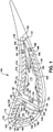
- FIG. 1 depicts an embodiment of a turbine component 100, such as a gas turbine airfoil, incorporating two sealing inserts 150, 175.
- Component 100 is an airfoil component operating in high temperature environment and requiring circulation of a cooling fluid, such as air that is cooler than the air outside the component, through an interior space.
- Component 100 includes an outer component wall (or walls) 110 defining a component interior space 112 and an exterior component surface 102.
- Outer component wall 110 is defined as a continuous wall defining and enclosing component interior space 112 or a plurality of adjoining walls, such as a front wall and two side walls around component interior space 112.
- Component 100 includes a component interior wall 114 separating component interior space 112 into a forward insert space 116 and a trailing insert space 118.
- component 100 includes a forward sealing insert 150 in forward insert space 116 and a trailing sealing insert 175 in trailing insert space 118.
- Outer component wall 110 defines a plurality of cooling fluid outlets 120, 122, 124, 126, 128, 130, 132.
- cooling fluid outlets 120, 122, 124, 126, 128, 130, 132 are grouped to provide outlets from separate portions of component interior space 112.
- cooling fluid outlets 120, 122, 124, 126 provide fluid outlets for forward insert space 116 and fluid outlets 128, 130, 132 provide fluid outlets for trailing insert space 118.
- component interior wall 114 includes one or more fluid paths, such as cooling fluid passage 134, to allow cooling fluid to pass between separate interior spaces, such as trailing insert space 118 and forward insert space 116.
- Outer component wall 110 and component interior wall 114 have an interior component surfaces 136, 138 defining and enclosing forward insert space 116 and trailing insert space 118, respectively.
- interior component surface 136 includes guide channels 140, 142, 144, 146, 148 for receiving and positioning compressible seals 162, 164, 186, 188, 190.
- Forward sealing insert 150 includes a forward insert wall (or walls) 152 defining and enclosing a forward insert interior space 154.
- Forward insert wall 152 is defined as a continuous wall defining and enclosing forward insert interior space 154 or a plurality of adjoining walls, such as a rear wall and two side walls around forward insert interior space 154.
- Forward insert interior space 154 receives the cooling fluid from an inlet in the base of component 100 for distribution through component interior space 112 and, more specifically for distribution into a forward cooling space 156.
- Forward insert wall 152 effectively divides forward insert space 116 between forward insert interior space 154 inside forward insert wall 152 and forward cooling space 156 outside of forward insert wall 152.
- Forward insert wall 152 has an insert wall inside surface 158 and an insert wall outside surface 160.
- Forward cooling space 156 is defined as the space between insert wall outside surface 160 and outer component wall 110 and forward surface of component interior wall 114.
- Forward sealing insert 150 includes several compressible seals 162, 164 extending from insert wall outside surface 160.
- Compressible seals 162, 164 include seals that are compressed prior to or during installation in component 100 and/or seals that expand during operation to create a compression force between outer component wall 110 and compressible seals 162, 164.
- Compressible seals 162, 164 divide forward cooling space 156 into multiple cooling compartments 166, 168.
- Compressible seals 162, 164 substantially prevent fluid flow between cooling compartments 166, 168 across compressible seals 162, 164.
- Cooling compartment 166 is defined by a portion of outer component wall 110, a portion of component interior wall 114, a portion of forward insert wall 152, and compressible seals 162, 164.
- Cooling compartment 168 is defined by a portion of component interior wall 114, a portion of outer component wall 110, a portion of forward insert wall 152, and compressible seals 162, 164. Cooling compartments 166, 168 receive cooling fluid through defined inlet paths and exhaust used cooling fluid through defined outlet paths. Impingement jets 170, 172 defined in forward insert wall 152 provide at least partial inlet paths for cooling compartments 166, 168. Impingement jets 170 provide a cooling fluid inlet to cooling compartment 166 from forward insert interior space 154. Impingement jet 172 along with cooling fluid passage 134 provide a cooling fluid inlet to cooling compartment 168.
- Cooling fluid outlets 120, 122, 124, 126 in outer component wall 110 provide outlet paths for cooling compartments 166, 168. Cooling fluid outlets 120, 122, 124 provide a cooling fluid outlet from cooling compartment 166 and cooling fluid outlet 126 provides a cooling fluid outlet from cooling compartment 168.
- cooling compartment 166 has separate cooling fluid inlets and outlets from cooling compartment 168, defining separate cooling fluid flow paths, volumes, and pressures to the different cooling compartments 166, 168 and the portions of component 100 that are to be cooled.
- Trailing sealing insert 175 includes a trailing insert wall (or walls) 176 defining and enclosing a trailing insert interior space 178.
- Trailing insert wall 176 is defined as a continuous wall defining and enclosing trailing insert interior space 178 or a plurality of adjoining walls, such as a rear wall and two side walls around forward insert interior space 178.
- Trailing insert interior space 178 receives the cooling fluid from an inlet in the base of component 100 for distribution through component interior space 112 and, more specifically for distribution into a trailing cooling space 180.
- Trailing insert wall 176 effectively divides trailing insert space 118 between trailing insert interior space 178 inside trailing insert wall 176 and trailing cooling space 180 outside of trailing insert wall 176.
- Trailing insert wall 176 has an insert wall inside surface 182 and an insert wall outside surface 184.
- Trailing cooling space 180 is defined as the space between insert wall outside surface 182 and outer component wall 110 and a trailing surface of component interior wall 114.
- Trailing sealing insert 175 includes several compressible seals 186, 188, 190 extending from insert wall outside surface 182.
- Compressible seals 186, 188, 190 include seals that are compressed prior to or during installation in component 100 and/or seals that expand during operation to create a compression force between outer component wall 110 and compressible seals 186, 188, 190.
- Compressible seals 186, 188, 190 divide trailing cooling space 180 into multiple cooling compartments 192, 194, 196.
- Compressible seals 186, 188, 190 substantially prevent fluid flow between adjacent cooling compartments 192, 194, 196 across compressible seals 186, 188, 190.
- cooling compartment 192 is defined by a portion of outer component wall 110, a portion of component interior wall 114, a portion of trailing insert wall 176, and compressible seals 186, 188.
- Cooling compartment 194 is defined by a portion of outer component wall 110, a portion of trailing insert wall 176, and compressible seals 188, 190.
- Cooling compartment 196 is defined by a portion of outer component wall 110, a portion of component interior wall 114, a portion of trailing insert wall 176, and compressible seals 186, 190.
- Cooling compartments 192, 194, 196 receive cooling fluid through defined inlet paths and exhaust used cooling fluid through defined outlet paths.
- impingement jets 197, 198, 199 defined in trailing insert wall 176 provide at least partial inlet paths for cooling compartments 192, 194, 196.
- Impingement jets 197 provide a cooling fluid inlet to cooling compartment 192 from trailing insert interior space 178.
- Impingement jet 198 provides a cooling fluid inlet to cooling compartment 194 from trailing insert interior space 178.
- Impingement jets 199 provide a cooling fluid inlet to cooling compartment 196 from trailing insert interior space 178.
- Cooling fluid outlets 128, 130, 132 in outer component wall 110 and cooling fluid passage 134 provide outlet paths for cooling compartments 192, 194, 196.
- cooling fluid outlets 128 provides a cooling fluid outlet from cooling compartment 192
- cooling fluid outlets 130, 132 provide cooling fluid outlets from cooling compartment 194
- cooling fluid passage 134 provides a cooling fluid outlet from cooling compartment 196.
- cooling compartment 192 has separate cooling fluid inlets and outlets from cooling compartments 194, 196
- cooling compartment 194 has separate cooling fluid inlets and outlets from cooling compartments 192, 196
- cooling compartment 196 has separate cooling fluid inlets and outlets from cooling compartments 192, 194, each defining separate cooling fluid flow paths, volumes, and pressures to the different cooling compartments 192, 194, 196 and the portions of component 100 that are to be cooled.
- FIG. 2 shows an embodiment of a sealing insert 200, such as used for forward sealing insert 150 in FIG. 1 .
- Sealing insert 200 includes an insert wall (or walls) 210 defining and enclosing an insert interior space 212.
- Insert wall 210 is defined as a continuous wall defining and enclosing insert interior space 212 or a plurality of adjoining walls, such as a rear wall 214 and two side walls 216, 218 around insert interior space 212.
- Insert wall 210 has an insert wall inside surface 220 and an insert wall outside surface 222.
- Insert wall 200 includes a plurality of impingement jets 224 or other outlets for cooling fluid defined by a passage through insert wall 210.
- insert wall 210 may include impingement jets 224 and their configurations (including number, size, spacing, pattern, output angle, etc.) may vary from one portion of insert wall 210 to another portion of insert wall 210. As shown, impingement jets 224 may be spaced vertically and horizontally around the surfaces of insert wall 210.
- Sealing insert 200 also includes compressible seals 230, 240.
- Compressible seals 230, 240 protrude or extend from insert wall outside surface 222.
- compressible seals 230, 240 extend substantially vertically along insert wall 210 for the height of sealing insert 200 such that they create cooling compartments adjacent sealing insert 200 in conjunction with the outer wall and other interior structures of the component into which sealing insert 200 is installed.
- Other orientations and configurations of compressible seals 230, 240 are possible to create desired cooling compartments and control cooling of adjacent portions of the component into which sealing insert 200 is installed.
- compressible seals with a horizontal orientation could be used to divide the component cooling space into vertical bands or a combination of horizontal, vertical, curved, or other seal configurations may be used to define any desired size, shape, and location of cooling compartments.
- the complexity of compressible seal shapes and configurations may be produced through an additive manufacturing process and, more specifically, a laser-sintered metal or direct metal laser melting (DMLM) manufacturing platform.
- sealing insert 200 may be manufactured entirely from laser-sintered metal as a continuous piece.
- insert wall 210 and compressible seals 230, 240 may be made of the same material and without a seam or attachment between insert wall outside surface 222 and compressible seals 230, 240.
- the component into which insert seal 200 is inserted may be manufactured by another process and using different materials, such as conventional casting and/or subtractive machining of the component.
- sealing insert 200 When manufactured using additive manufacturing, sealing insert 200 may have a build direction coincident with the Z axis describing the direction in which materials were added to form the desired structure.
- a "build direction" of one or more components may be defined by a fabricator before raw materials are processed from raw materials into a desired structure.
- a build direction for a given component and/or sub-component therefore defines the order in which structural features are formed over time as raw materials (e.g., metallic powders) are sintered to form a structure.
- raw materials e.g., metallic powders
- Such materials can include, e.g., one or more pure metals and/or alloys including without limitation: Copper (Cu), Chromium (Cr), Titanium (Ti), Nickel (Ni), aluminum (Al), etc.
- the build direction Z of sealing insert 200 can be oriented along one axis, and perpendicular to the plane of X and Y axis, and generally can be defined to assist in describing the three dimensional structure of the component, as well as the way in which it is formed.
- Sealing insert 200 is provided as an example only and variety of geometric shapes and configurations of insert wall 210 and compressible seals 230, 240 are possible. Regardless of the geometrical shape and configuration of sealing insert 200, sealing insert 200 can be composed of one or more laser-sintered metals or metallic materials, e.g., those currently-known or later developed for use in an additive manufacturing process.
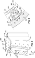
- FIG. 3 shows an embodiment of a configuration of a compressible seal 300 engaged with interior surface 354 of an outer component wall 352 of a component 350 in which compressible seal 300 is installed.
- Compressible seal 300 may be a "bellows-seal” that is installed relative to component 350 in a relaxed state and then expanded by a pressure differential between insert interior space 302 and cooling space 304 adjacent outer component wall 352. In an expanded state, compressible seal 300 creates a compression force between a distal end 306 of compressible seal 300 and interior surface 354 of component 350.
- compressible seal 300 is comprised of a spring/bellows wall (or walls) 316, 318 defining and enclosing a seal interior space 312 that is separate from cooling space 304 and has a restricted inlet 314 from insert interior space 302.
- Spring/bellows wall 310 may be defined as a continuous wall defining and enclosing seal interior space 312 or a plurality of adjoining walls, such as lateral spring/bellows walls 316, 318 and distal seal wall 330, further adjoining insert wall 308 around seal interior space 312.
- compressible seal 300 may include lateral supports 322, 324 traversing seal interior space 312 to connect and support lateral spring/bellows walls 316, 318, and defining support through holes 326, 328 to allow fluid flow and pressure equalization throughout seal interior space 312.
- interior surface 354 of component 350 also defines a guide channel 356 between guide rails 358, 360.
- the guide channel width between guide rails 358, 360 is greater than the width of distal end 306 of distal seal wall 320 to accommodate, locate, and retain compressible seal 300 relative to interior surface 354 of component 350.
- Guide channel 356 can be formed in a number of alternative ways other than through guide rails 358, 360.
- guide channel 356 may be formed as a recess in interior surface 354.
- FIG. 4 shows a plurality of example compressible seals 420, 440, 460 not forming part of the claimed subject matter and extending from an insert wall 402 of a sealing insert 400 and engaged with interior surface 414 of an outer component wall 412 of a component 410 in which sealing insert 400 is installed.
- Compressible seals 420, 440, 460 may be compressible spring/bellows seals each formed of at least one spring/bellows wall extending from exterior surface 404 of insert wall 402 to interior surface 414 of outer component wall 412 and held in compression when installed.
- each spring/bellows wall may be wider than cooling space 406 between exterior surface 404 and interior surface 414 such that the spring/bellows are compressed in response to sealing insert 400 being inserted into component 410.
- Compressible seals 420, 440, 460 create a seal between sealing insert 400 and component 410 to divide cooling space 406 into separate cooling compartments.
- Compressible seal 420 is a zigzag spring/bellows 422 comprised of a plurality of flat portions connected by angled junctions.
- Compressible seal 420 may include a flat insert wall interface 424 and a flat distal end interface 426.
- Insert wall interface 424 is made continuous with insert wall 402 and distal end interface 426 is physically separate from outer component wall 412 and held in place against interior surface 414 by the compression force on compressible seal 420.
- Compressible seal 440 is a "W" spring/bellows 442 supported by a split base 444 and demonstrates more complex spring/bellows and interface structures.
- Compressible seal 440 may include split base 444 with insert wall interfaces 446, 448 and defining an internal support space 450.
- internal support space 450 may not be designed for expansion and includes an internally sealed space or one or more pressure outlets to allow it to equalize with one (but not both) of the adjacent cooling compartments.
- distal end interface 452 is a compressed portion of the "W" spring/bellows 442.
- Insert wall interfaces 446, 448 is made continuous with insert wall 402 and distal end interface 452 is physically separate from outer component wall 412 and held in place against interior surface 414 by the compression force on compressible seal 440.
- interior surface 414 of component 410 also defines a guide channel 416 between guide rails 418, 419. The guide channel width between guide rails 418, 419 is greater than the width of distal surface 454 of distal end interface 452 to accommodate, locate, and retain compressible seal 440 relative to interior surface 414 of component 410.
- Compressible seal 460 is a wave spring/bellows 462 comprised of a plurality of curved portions in sequentially opposed orientations.
- Compressible seal 460 includes a flat insert wall interface 464 and a flat distal end interface 466. Insert wall interface 464 is made continuous with insert wall 402 and distal end interface 466 is physically separate from outer component wall 412 and held in place against interior surface 414 by the compression force on compressible seal 460.
- additive manufacturing is particularly suited for manufacturing sealing inserts 150, 175, 200 and compressible seals 300, 420, 440, 460.
- additive manufacturing may include any process of producing an object through the successive layering of material rather than the removal of material, which is the case with conventional processes.
- Additive manufacturing can create complex geometries without the use of any sort of tools, molds or fixtures, and with little or no waste material. Instead of machining components from solid billets of metal, much of which is cut away and discarded, the only material used in additive manufacturing is what is required to shape the part.
- Additive manufacturing processes may include but are not limited to: 3D printing, rapid prototyping (RP), direct digital manufacturing (DDM), selective laser melting (SLM) and direct metal laser melting (DMLM). In the current setting, DMLM has been found advantageous.
- FIG. 5 shows a schematic/block view of an illustrative computerized additive manufacturing system 900 for generating an object 902.
- system 900 is arranged for DMLM. It is understood that the general teachings of the disclosure are equally applicable to other forms of additive manufacturing.
- Object 902 is illustrated as a double walled turbine element; however, it is understood that the additive manufacturing process can be readily adapted to manufacture sealing inserts.
- AM system 900 generally includes a computerized additive manufacturing (AM) control system 904 and an AM printer 906.
- AM computerized additive manufacturing
- AM system 900 executes code 920 that includes a set of computer-executable instructions defining sealing inserts 150, 175, 200 and compressible seals 300, 420, 440, 460 to physically generate one or more of these objects using AM printer 906.
- Each AM process may use different raw materials in the form of, for example, fine-grain powder, liquid (e.g., polymers), sheet, etc., a stock of which may be held in a chamber 910 of AM printer 906.
- sealing inserts 150, 175, 200 and compressible seals 300, 420, 440, 460 may be made of stainless steel or similar materials.
- an applicator 912 may create a thin layer of raw material 914 spread out as the blank canvas from which each successive slice of the final object will be created.
- applicator 912 may directly apply or print the next layer onto a previous layer as defined by code 920, e.g., where the material is a polymer.
- a laser or electron beam 916 fuses particles for each slice, as defined by code 920.
- Various parts of AM printer 906 may move to accommodate the addition of each new layer, e.g., a build platform 918 may lower and/or chamber 910 and/or applicator 912 may rise after each layer.
- AM control system 904 is shown implemented on computer 930 as computer program code.
- computer 930 is shown including a memory 932, a processor 934, an input/output (I/O) interface 936, and a bus 938. Further, computer 930 is shown in communication with an external I/O device/resource 940 and a storage system 942.
- processor 934 executes computer program code, such as AM control system 904, that is stored in memory 932 and/or storage system 942 under instructions from code 920 representative of sealing inserts 150, 175, 200 and compressible seals 300, 420, 440, 460, described herein.
- processor 934 can read and/or write data to/from memory 932, storage system 942, I/O device 940 and/or AM printer 906.
- Bus 938 provides a communication link between each of the components in computer 930, and I/O device 940 can comprise any device that enables a user to interact with computer 940 (e.g., keyboard, pointing device, display, etc.).
- Computer 930 is only representative of various possible combinations of hardware and software.
- processor 934 may comprise a single processing unit, or be distributed across one or more processing units in one or more locations, e.g., on a client and server.
- memory 932 and/or storage system 942 may reside at one or more physical locations.
- Memory 932 and/or storage system 942 can comprise any combination of various types of non-transitory computer readable storage medium including magnetic media, optical media, random access memory (RAM), read only memory (ROM), etc.
- Computer 930 can comprise any type of computing device such as a network server, a desktop computer, a laptop, a handheld device, a mobile phone, a pager, a personal data assistant, etc.
- Additive manufacturing processes begin with a non-transitory computer readable storage medium (e.g., memory 932, storage system 942, etc.) storing code 920 representative of sealing inserts 150, 175, 200 and compressible seals 300, 420, 440, 460.
- code 920 includes a set of computer-executable instructions defining outer electrode that can be used to physically generate the tip, upon execution of the code by system 900.
- code 920 may include a precisely defined 3D model of outer electrode and can be generated from any of a large variety of well-known computer aided design (CAD) software systems such as AutoCAD®, TurboCAD®, DesignCAD 3D Max, etc.
- CAD computer aided design
- code 920 can take any now known or later developed file format.
- code 920 may be in the Standard Tessellation Language (STL) which was created for stereolithography CAD programs of 3D Systems, or an additive manufacturing file (AMF), which is an American Society of Mechanical Engineers (ASME) standard that is an extensible markup-language (XML) based format designed to allow any CAD software to describe the shape and composition of any three-dimensional object to be fabricated on any AM printer.
- STL Standard Tessellation Language
- AMF additive manufacturing file
- ASME American Society of Mechanical Engineers
- XML extensible markup-language
- Code 920 may be translated between different formats, converted into a set of data signals and transmitted, received as a set of data signals and converted to code, stored, etc., as necessary.
- Code 920 may be an input to system 900 and may come from a part designer, an intellectual property (IP) provider, a design company, the operator or owner of system 900, or from other sources.
- IP intellectual property
- AM control system 904 executes code 920, dividing sealing inserts 150, 175, 200 and compressible seals 300, 420, 440, 460 into a series of thin slices that it assembles using AM printer 906 in successive layers of liquid, powder, sheet or other material.
- each layer is melted to the exact geometry defined by code 920 and fused to the preceding layer.
- the outer electrode may be exposed to any variety of finishing processes, e.g., minor machining, sealing, polishing, assembly to other part of sealing inserts 150, 175, 200 and compressible seals 300, 420, 440, 460, etc.
Landscapes
- Engineering & Computer Science (AREA)
- Mechanical Engineering (AREA)
- General Engineering & Computer Science (AREA)
- Manufacturing & Machinery (AREA)
- Chemical & Material Sciences (AREA)
- Materials Engineering (AREA)
- Powder Metallurgy (AREA)
Claims (5)
- Turbinenkomponente (100, 350), umfassend:eine Komponentenwand (110, 352), die einen Komponenteninnenraum (112) definiert;einen Dichtungseinsatz (150, 175, 200), der mindestens eine Einsatzwand (152, 176, 210, 308) einschließt, die einen Einsatzinnenraum (154, 178, 212, 302) definiert und umschließt, und in den Komponenteninnenraum (112) eingesetzt ist, um einen Raum (116, 118, 304) zwischen der mindestens einen Einsatzwand und der Komponentenwand zu definieren;mindestens eine komprimierbare Dichtung (162, 164, 186, 188, 190, 230, 240, 300), die in der Turbinenkomponente (100, 350) zwischen der mindestens einen Einsatzwand (152, 176, 210, 308) und der Komponentenwand (110, 352) installiert ist, wobei die komprimierbare Dichtung (162, 164, 186, 188, 190, 230, 240, 300) mit einer Innenoberfläche (354) der Komponentenwand (110, 352) in Eingriff ist, wobei die mindestens eine komprimierbare Dichtung den Raum (116, 118) in eine Vielzahl von Kühlkammern (166, 168, 192, 194, 196) aufteilt und die Vielzahl von Kühlkammern jeweils mindestens einen Fluideinlass (170, 172, 197, 198, 199) und mindestens einen Fluidauslass (120, 122, 124, 126, 128, 130, 132) aufweist, die von jeder anderen Kühlkammer getrennt sind, wobei die mindestens eine Einsatzwand (152, 176, 210, 308) eine erste Konfiguration von Aufpralldüsen (170, 197) als erste Fluideinlässe in eine erste Kammer (166, 192) der Vielzahl von Kühlkammern aus dem Einsatzinnenraum (154, 178, 212, 302) und eine zweite Konfiguration von Aufpralldüsen (172, 199) als zweite Fluideinlässe in eine zweite Kammer (168, 196) der Vielzahl von Kühlkammern aus dem Einsatzinnenraum definiert, und wobei erste (120, 122, 124, 128) der in der Komponentenwand (110, 352) angeordneten Fluidauslässe Auslasspfade für die erste Kammer (166, 192) und zweite (126) der Fluidauslässe Auslasspfade für die zweite Kammer (168, 196) bereitstellen, dadurch gekennzeichnet, dass die mindestens eine komprimierbare Dichtung (300) mindestens eine Federwand (316, 318, 330) einschließt, die kontinuierlich mit einer Außenoberfläche (158, 160, 182, 184, 220, 222) der Einsatzwand (152, 176, 210, 308) ausgebildet ist und von dieser vorsteht oder sich von dieser erstreckt und einen Dichtungsinnenraum (312) definiert, der von der Vielzahl von Kühlkammern getrennt ist, unddass die mindestens eine Einsatzwand mindestens eine Öffnung (314) zwischen dem Einsatzinnenraum (302) und dem Dichtungsinnenraum (312) einschließt.
- Turbinenkomponente nach Anspruch 1, wobei die mindestens eine Einsatzwand (152, 176, 210, 308) und die mindestens eine komprimierbare Dichtung (162, 164, 186, 188, 190, 230, 240, 300) eine einzelne Metallkomponente sind, die aus einer lasergeschmolzenen Komponente oder einer lasergesinterten Komponente ausgewählt ist.
- Turbinenkomponente nach einem der Ansprüche 1 oder 2, wobei die mindestens eine komprimierbare Dichtung (162, 164, 186, 188, 190, 230, 240, 300) ein distales Ende (306) mit einer distalen Oberfläche an einer distalen Dichtungswand (330) zum Eingriff mit der Komponentenwand (110, 352) einschließt, wobei die distale Oberfläche eine Dichtungsbreite aufweist, die geringer ist als eine Führungsbreite eines in der Komponentenwand (110, 352) ausgebildeten Führungskanals (356), wobei der Führungskanal durch die Innenoberfläche (354) der Komponente (100, 350) zwischen Führungsschienen (358, 360) definiert ist, um die mindestens eine komprimierbare Dichtung relativ zu der Innenoberfläche der Komponente (100, 350) aufzunehmen, zu positionieren und zu halten.
- Turbinenkomponente nach einem der Ansprüche 1 oder 2, wobei die mindestens eine komprimierbare Dichtung (162, 164, 186, 188, 190, 230, 240, 300) eine Faltenbalgdichtung ist, die aus seitlichen Feder-/Faltenbalgwänden (316, 318) und einer distalen Dichtungswand (330) besteht, die den Dichtungsinnenraum (312) definieren und umschließen, und durch eine Druckdifferenz zwischen dem Einsatzinnenraum (302) und dem Raum (304) zwischen der mindestens einen Einsatzwand (308) und der Komponentenwand (352) expandierbar ist, wobei in einem expandierten Zustand eine Kompressionskraft zwischen der distalen Dichtungswand (330) und der Innenoberfläche (354) der Komponentenwand (352) erzeugt wird, und wobei die Faltenbalgdichtung seitliche Träger (322, 324) einschließt, die den Dichtungsinnenraum (312) durchqueren, um die seitlichen Feder-/Faltenbalgwände (316, 318) zu verbinden und zu stützen, und Stützdurchgangslöcher (326, 328) definieren, um einen fluidischen Strom und einen Druckausgleich durch den gesamten Dichtungsinnenraum (312) zu ermöglichen.
- Turbinenkomponente nach Anspruch 3, wobei die mindestens eine komprimierbare Dichtung (162, 164, 186, 188, 190, 230, 240, 300) eine Faltenbalgdichtung ist, die aus seitlichen Feder-/Faltenbalgwänden (316, 318) und der distalen Dichtungswand (330) besteht, die den Dichtungsinnenraum (312) begrenzen und umschließen, und durch eine Druckdifferenz zwischen dem Einsatzinnenraum (302) und dem Raum (304) zwischen der mindestens einen Einsatzwand (308) und der Komponentenwand (352) expandierbar ist, wobei in einem expandierten Zustand eine Kompressionskraft zwischen der distalen Dichtungswand (330) und der Innenoberfläche (354) der Komponentenwand (352) erzeugt wird, und wobei die Faltenbalgdichtung seitliche Träger (322, 324) einschließt, die den Dichtungsinnenraum (312) durchqueren, um die seitlichen Feder-/Faltenbalgwände (316, 318) zu verbinden und zu stützen, und Stützdurchgangslöcher (326, 328) definieren, um einen Fluidfluss und einen Druckausgleich durch den gesamten Dichtungsinnenraum (312) zu ermöglichen.
Applications Claiming Priority (1)
| Application Number | Priority Date | Filing Date | Title |
|---|---|---|---|
| US15/372,642 US10260363B2 (en) | 2016-12-08 | 2016-12-08 | Additive manufactured seal for insert compartmentalization |
Publications (2)
| Publication Number | Publication Date |
|---|---|
| EP3333367A1 EP3333367A1 (de) | 2018-06-13 |
| EP3333367B1 true EP3333367B1 (de) | 2021-06-02 |
Family
ID=60569718
Family Applications (1)
| Application Number | Title | Priority Date | Filing Date |
|---|---|---|---|
| EP17204881.1A Active EP3333367B1 (de) | 2016-12-08 | 2017-12-01 | Generativ gefertigte dichtung für kammerbildung an einem einsatz in einer turbinenkomponente |
Country Status (2)
| Country | Link |
|---|---|
| US (1) | US10260363B2 (de) |
| EP (1) | EP3333367B1 (de) |
Families Citing this family (14)
| Publication number | Priority date | Publication date | Assignee | Title |
|---|---|---|---|---|
| FR3028881B1 (fr) * | 2014-11-21 | 2016-11-25 | Trelleborg Sealing Solutions France | Dispositif formant joint d’etancheite pour une vanne de decharge dans une turbomachine |
| US11118467B2 (en) * | 2017-07-26 | 2021-09-14 | General Electric Company | System and method for converting turbine cooling nozzle |
| US11293347B2 (en) * | 2018-11-09 | 2022-04-05 | Raytheon Technologies Corporation | Airfoil with baffle showerhead and cooling passage network having aft inlet |
| US11078844B2 (en) | 2018-11-21 | 2021-08-03 | Raytheon Technologies Corporation | Thermal gradient reducing device for gas turbine engine component |
| US10815794B2 (en) * | 2018-12-05 | 2020-10-27 | Raytheon Technologies Corporation | Baffle for components of gas turbine engines |
| US11231107B2 (en) * | 2019-11-22 | 2022-01-25 | Transportation Ip Holdings, Llc | Seal structure and method of forming |
| US11085374B2 (en) * | 2019-12-03 | 2021-08-10 | General Electric Company | Impingement insert with spring element for hot gas path component |
| DE102020103777B4 (de) * | 2020-02-13 | 2022-04-28 | Doosan Heavy Industries & Construction Co., Ltd. | Pralleinsatz für eine Turbomaschinenkomponente, Turbomaschinenkomponente und damit versehene Gasturbine |
| DE102020106135B4 (de) * | 2020-03-06 | 2023-08-17 | Doosan Enerbility Co., Ltd. | Strömungsmaschinenkomponente für eine gasturbine, strömungsmaschinenanordnung und gasturbine mit derselben |
| US11203981B1 (en) | 2020-08-06 | 2021-12-21 | Raytheon Technologies Corporation | Baffle systems for airfoils |
| US11499443B2 (en) * | 2020-12-21 | 2022-11-15 | Raytheon Technologies Corporation | Ceramic wall seal interface cooling |
| US20220339878A1 (en) * | 2021-04-23 | 2022-10-27 | Essentium, Inc. | Four mode additive manufacturing machine |
| US11905842B2 (en) * | 2021-12-16 | 2024-02-20 | General Electric Company | Partition damper seal configurations for segmented internal cooling hardware |
| US12319417B2 (en) | 2023-02-17 | 2025-06-03 | General Electric Company | Reverse flow gas turbine engine having electric machine |
Family Cites Families (31)
| Publication number | Priority date | Publication date | Assignee | Title |
|---|---|---|---|---|
| US3767322A (en) | 1971-07-30 | 1973-10-23 | Westinghouse Electric Corp | Internal cooling for turbine vanes |
| US3891348A (en) * | 1972-04-24 | 1975-06-24 | Gen Electric | Turbine blade with increased film cooling |
| GB1400285A (en) | 1972-08-02 | 1975-07-16 | Rolls Royce | Hollow cooled vane or blade for a gas turbine engine |
| GB1587401A (en) | 1973-11-15 | 1981-04-01 | Rolls Royce | Hollow cooled vane for a gas turbine engine |
| GB1565361A (en) * | 1976-01-29 | 1980-04-16 | Rolls Royce | Blade or vane for a gas turbine engien |
| US4297077A (en) * | 1979-07-09 | 1981-10-27 | Westinghouse Electric Corp. | Cooled turbine vane |
| FR2490721B1 (fr) | 1980-09-19 | 1987-10-09 | Rockwell International Corp | Turbomachine dont les aubages mobile et fixe sont proteges par une carapace en ceramique |
| IN163070B (de) | 1984-11-15 | 1988-08-06 | Westinghouse Electric Corp | |
| JP3142850B2 (ja) * | 1989-03-13 | 2001-03-07 | 株式会社東芝 | タービンの冷却翼および複合発電プラント |
| US6183192B1 (en) * | 1999-03-22 | 2001-02-06 | General Electric Company | Durable turbine nozzle |
| US6283708B1 (en) * | 1999-12-03 | 2001-09-04 | United Technologies Corporation | Coolable vane or blade for a turbomachine |
| US6464456B2 (en) | 2001-03-07 | 2002-10-15 | General Electric Company | Turbine vane assembly including a low ductility vane |
| US6742991B2 (en) | 2002-07-11 | 2004-06-01 | Mitsubishi Heavy Industries, Ltd. | Turbine blade and gas turbine |
| US7121796B2 (en) | 2004-04-30 | 2006-10-17 | General Electric Company | Nozzle-cooling insert assembly with cast-in rib sections |
| US8714565B1 (en) | 2005-01-27 | 2014-05-06 | Parker-Hannifim Corporation | Seal |
| US7452189B2 (en) | 2006-05-03 | 2008-11-18 | United Technologies Corporation | Ceramic matrix composite turbine engine vane |
| US8251652B2 (en) | 2008-09-18 | 2012-08-28 | Siemens Energy, Inc. | Gas turbine vane platform element |
| US8956105B2 (en) | 2008-12-31 | 2015-02-17 | Rolls-Royce North American Technologies, Inc. | Turbine vane for gas turbine engine |
| US8079821B2 (en) | 2009-05-05 | 2011-12-20 | Siemens Energy, Inc. | Turbine airfoil with dual wall formed from inner and outer layers separated by a compliant structure |
| CH701031A1 (de) | 2009-05-15 | 2010-11-15 | Alstom Technology Ltd | Verfahren zum Aufarbeiten einer Turbinenschaufel. |
| US8714911B2 (en) | 2011-01-06 | 2014-05-06 | General Electric Company | Impingement plate for turbomachine components and components equipped therewith |
| US8777569B1 (en) | 2011-03-16 | 2014-07-15 | Florida Turbine Technologies, Inc. | Turbine vane with impingement cooling insert |
| US20120243995A1 (en) * | 2011-03-21 | 2012-09-27 | General Electric Company | Components with cooling channels formed in coating and methods of manufacture |
| ES2531065T3 (es) | 2011-12-19 | 2015-03-10 | Siemens Ag | Alabe para una turbomáquina |
| US8556578B1 (en) | 2012-08-15 | 2013-10-15 | Florida Turbine Technologies, Inc. | Spring loaded compliant seal for high temperature use |
| JP6245740B2 (ja) * | 2013-11-20 | 2017-12-13 | 三菱日立パワーシステムズ株式会社 | ガスタービン翼 |
| GB201403008D0 (en) * | 2014-02-20 | 2014-04-09 | Rolls Royce Plc | Machine cavity seal |
| US10207325B2 (en) | 2014-06-16 | 2019-02-19 | Delavan Inc. | Additive manufacture from machined surface |
| US9988913B2 (en) | 2014-07-15 | 2018-06-05 | United Technologies Corporation | Using inserts to balance heat transfer and stress in high temperature alloys |
| US9896954B2 (en) * | 2014-10-14 | 2018-02-20 | Rolls-Royce Corporation | Dual-walled ceramic matrix composite (CMC) component with integral cooling and method of making a CMC component with integral cooling |
| EP3075531B1 (de) | 2015-03-31 | 2024-03-20 | Ansaldo Energia IP UK Limited | Sandwichanordnung mit keramikplatten und keramikfilzen |
-
2016
- 2016-12-08 US US15/372,642 patent/US10260363B2/en active Active
-
2017
- 2017-12-01 EP EP17204881.1A patent/EP3333367B1/de active Active
Non-Patent Citations (1)
| Title |
|---|
| None * |
Also Published As
| Publication number | Publication date |
|---|---|
| US20180163555A1 (en) | 2018-06-14 |
| EP3333367A1 (de) | 2018-06-13 |
| US10260363B2 (en) | 2019-04-16 |
Similar Documents
| Publication | Publication Date | Title |
|---|---|---|
| EP3333367B1 (de) | Generativ gefertigte dichtung für kammerbildung an einem einsatz in einer turbinenkomponente | |
| EP3014496B1 (de) | Verfahren zur generativen fertigung | |
| EP3413001B1 (de) | Generativ hergestellter wärmetauscher | |
| US9757936B2 (en) | Hot gas path component | |
| US10519777B2 (en) | Tip member for blade structure and related method to form turbomachine component | |
| EP3346093B1 (de) | Generativ gefertigte schaufelerweiterung mit internen kühl-merkmalen | |
| US10914185B2 (en) | Additive manufactured case with internal passages for active clearance control | |
| JP7023628B2 (ja) | 衝突熱伝達機能部を有するターボマシン構成要素、関連するターボマシンおよび記憶媒体 | |
| JP7346254B2 (ja) | 複数のノズルおよびベンチュリを含む高温ガス経路構成要素 | |
| EP4031750B1 (de) | Leitapparat mit integriertem deckband mit optimierter leitschaufelwanddicke | |
| US10927693B2 (en) | Unitary body turbine shroud for turbine systems | |
| US10822986B2 (en) | Unitary body turbine shrouds including internal cooling passages | |
| EP3663524B1 (de) | Axialflusskühlschema mit struktureller rippe für ein gasturbinentriebwerk | |
| US20200392853A1 (en) | Hot gas path component with metering structure including converging-diverging passage portions | |
| US10376958B2 (en) | Removable support for additive manufacture | |
| JP7471803B2 (ja) | 複数のノズルおよびベンチュリを含む翼形部 | |
| KR20190143797A (ko) | 단열용 코팅 포획 피처를 갖는 터보기계 구성 요소 | |
| JP2025535421A (ja) | 熱フレックス要素を有するインピンジメント冷却構造を備えたタービンノズルまたはブレード | |
| EP3825523B1 (de) | Integrales turbinendeckband mit geformten kugelstrahlgittern und entsprechendes turbinensystem | |
| EP4707536A1 (de) | Schaufelkomponente für turbomaschinenkomponente mit plattformkühlung unter verwendung der schaufelkühlung |
Legal Events
| Date | Code | Title | Description |
|---|---|---|---|
| PUAI | Public reference made under article 153(3) epc to a published international application that has entered the european phase |
Free format text: ORIGINAL CODE: 0009012 |
|
| STAA | Information on the status of an ep patent application or granted ep patent |
Free format text: STATUS: THE APPLICATION HAS BEEN PUBLISHED |
|
| AK | Designated contracting states |
Kind code of ref document: A1 Designated state(s): AL AT BE BG CH CY CZ DE DK EE ES FI FR GB GR HR HU IE IS IT LI LT LU LV MC MK MT NL NO PL PT RO RS SE SI SK SM TR |
|
| AX | Request for extension of the european patent |
Extension state: BA ME |
|
| STAA | Information on the status of an ep patent application or granted ep patent |
Free format text: STATUS: REQUEST FOR EXAMINATION WAS MADE |
|
| 17P | Request for examination filed |
Effective date: 20181213 |
|
| RBV | Designated contracting states (corrected) |
Designated state(s): AL AT BE BG CH CY CZ DE DK EE ES FI FR GB GR HR HU IE IS IT LI LT LU LV MC MK MT NL NO PL PT RO RS SE SI SK SM TR |
|
| STAA | Information on the status of an ep patent application or granted ep patent |
Free format text: STATUS: EXAMINATION IS IN PROGRESS |
|
| 17Q | First examination report despatched |
Effective date: 20190628 |
|
| GRAP | Despatch of communication of intention to grant a patent |
Free format text: ORIGINAL CODE: EPIDOSNIGR1 |
|
| STAA | Information on the status of an ep patent application or granted ep patent |
Free format text: STATUS: GRANT OF PATENT IS INTENDED |
|
| INTG | Intention to grant announced |
Effective date: 20210115 |
|
| GRAS | Grant fee paid |
Free format text: ORIGINAL CODE: EPIDOSNIGR3 |
|
| GRAA | (expected) grant |
Free format text: ORIGINAL CODE: 0009210 |
|
| STAA | Information on the status of an ep patent application or granted ep patent |
Free format text: STATUS: THE PATENT HAS BEEN GRANTED |
|
| REG | Reference to a national code |
Ref country code: CH Ref legal event code: EP |
|
| AK | Designated contracting states |
Kind code of ref document: B1 Designated state(s): AL AT BE BG CH CY CZ DE DK EE ES FI FR GB GR HR HU IE IS IT LI LT LU LV MC MK MT NL NO PL PT RO RS SE SI SK SM TR |
|
| REG | Reference to a national code |
Ref country code: GB Ref legal event code: FG4D |
|
| REG | Reference to a national code |
Ref country code: AT Ref legal event code: REF Ref document number: 1398602 Country of ref document: AT Kind code of ref document: T Effective date: 20210615 |
|
| REG | Reference to a national code |
Ref country code: IE Ref legal event code: FG4D |
|
| REG | Reference to a national code |
Ref country code: DE Ref legal event code: R096 Ref document number: 602017039592 Country of ref document: DE |
|
| REG | Reference to a national code |
Ref country code: LT Ref legal event code: MG9D |
|
| PG25 | Lapsed in a contracting state [announced via postgrant information from national office to epo] |
Ref country code: FI Free format text: LAPSE BECAUSE OF FAILURE TO SUBMIT A TRANSLATION OF THE DESCRIPTION OR TO PAY THE FEE WITHIN THE PRESCRIBED TIME-LIMIT Effective date: 20210602 Ref country code: LT Free format text: LAPSE BECAUSE OF FAILURE TO SUBMIT A TRANSLATION OF THE DESCRIPTION OR TO PAY THE FEE WITHIN THE PRESCRIBED TIME-LIMIT Effective date: 20210602 Ref country code: BG Free format text: LAPSE BECAUSE OF FAILURE TO SUBMIT A TRANSLATION OF THE DESCRIPTION OR TO PAY THE FEE WITHIN THE PRESCRIBED TIME-LIMIT Effective date: 20210902 Ref country code: HR Free format text: LAPSE BECAUSE OF FAILURE TO SUBMIT A TRANSLATION OF THE DESCRIPTION OR TO PAY THE FEE WITHIN THE PRESCRIBED TIME-LIMIT Effective date: 20210602 |
|
| REG | Reference to a national code |
Ref country code: NL Ref legal event code: MP Effective date: 20210602 |
|
| REG | Reference to a national code |
Ref country code: AT Ref legal event code: MK05 Ref document number: 1398602 Country of ref document: AT Kind code of ref document: T Effective date: 20210602 |
|
| PG25 | Lapsed in a contracting state [announced via postgrant information from national office to epo] |
Ref country code: LV Free format text: LAPSE BECAUSE OF FAILURE TO SUBMIT A TRANSLATION OF THE DESCRIPTION OR TO PAY THE FEE WITHIN THE PRESCRIBED TIME-LIMIT Effective date: 20210602 Ref country code: GR Free format text: LAPSE BECAUSE OF FAILURE TO SUBMIT A TRANSLATION OF THE DESCRIPTION OR TO PAY THE FEE WITHIN THE PRESCRIBED TIME-LIMIT Effective date: 20210903 Ref country code: RS Free format text: LAPSE BECAUSE OF FAILURE TO SUBMIT A TRANSLATION OF THE DESCRIPTION OR TO PAY THE FEE WITHIN THE PRESCRIBED TIME-LIMIT Effective date: 20210602 Ref country code: SE Free format text: LAPSE BECAUSE OF FAILURE TO SUBMIT A TRANSLATION OF THE DESCRIPTION OR TO PAY THE FEE WITHIN THE PRESCRIBED TIME-LIMIT Effective date: 20210602 Ref country code: PL Free format text: LAPSE BECAUSE OF FAILURE TO SUBMIT A TRANSLATION OF THE DESCRIPTION OR TO PAY THE FEE WITHIN THE PRESCRIBED TIME-LIMIT Effective date: 20210602 Ref country code: NO Free format text: LAPSE BECAUSE OF FAILURE TO SUBMIT A TRANSLATION OF THE DESCRIPTION OR TO PAY THE FEE WITHIN THE PRESCRIBED TIME-LIMIT Effective date: 20210902 |
|
| PG25 | Lapsed in a contracting state [announced via postgrant information from national office to epo] |
Ref country code: SM Free format text: LAPSE BECAUSE OF FAILURE TO SUBMIT A TRANSLATION OF THE DESCRIPTION OR TO PAY THE FEE WITHIN THE PRESCRIBED TIME-LIMIT Effective date: 20210602 Ref country code: SK Free format text: LAPSE BECAUSE OF FAILURE TO SUBMIT A TRANSLATION OF THE DESCRIPTION OR TO PAY THE FEE WITHIN THE PRESCRIBED TIME-LIMIT Effective date: 20210602 Ref country code: EE Free format text: LAPSE BECAUSE OF FAILURE TO SUBMIT A TRANSLATION OF THE DESCRIPTION OR TO PAY THE FEE WITHIN THE PRESCRIBED TIME-LIMIT Effective date: 20210602 Ref country code: CZ Free format text: LAPSE BECAUSE OF FAILURE TO SUBMIT A TRANSLATION OF THE DESCRIPTION OR TO PAY THE FEE WITHIN THE PRESCRIBED TIME-LIMIT Effective date: 20210602 Ref country code: AT Free format text: LAPSE BECAUSE OF FAILURE TO SUBMIT A TRANSLATION OF THE DESCRIPTION OR TO PAY THE FEE WITHIN THE PRESCRIBED TIME-LIMIT Effective date: 20210602 Ref country code: PT Free format text: LAPSE BECAUSE OF FAILURE TO SUBMIT A TRANSLATION OF THE DESCRIPTION OR TO PAY THE FEE WITHIN THE PRESCRIBED TIME-LIMIT Effective date: 20211004 Ref country code: RO Free format text: LAPSE BECAUSE OF FAILURE TO SUBMIT A TRANSLATION OF THE DESCRIPTION OR TO PAY THE FEE WITHIN THE PRESCRIBED TIME-LIMIT Effective date: 20210602 Ref country code: NL Free format text: LAPSE BECAUSE OF FAILURE TO SUBMIT A TRANSLATION OF THE DESCRIPTION OR TO PAY THE FEE WITHIN THE PRESCRIBED TIME-LIMIT Effective date: 20210602 Ref country code: ES Free format text: LAPSE BECAUSE OF FAILURE TO SUBMIT A TRANSLATION OF THE DESCRIPTION OR TO PAY THE FEE WITHIN THE PRESCRIBED TIME-LIMIT Effective date: 20210602 |
|
| REG | Reference to a national code |
Ref country code: DE Ref legal event code: R097 Ref document number: 602017039592 Country of ref document: DE |
|
| PLBE | No opposition filed within time limit |
Free format text: ORIGINAL CODE: 0009261 |
|
| STAA | Information on the status of an ep patent application or granted ep patent |
Free format text: STATUS: NO OPPOSITION FILED WITHIN TIME LIMIT |
|
| PG25 | Lapsed in a contracting state [announced via postgrant information from national office to epo] |
Ref country code: DK Free format text: LAPSE BECAUSE OF FAILURE TO SUBMIT A TRANSLATION OF THE DESCRIPTION OR TO PAY THE FEE WITHIN THE PRESCRIBED TIME-LIMIT Effective date: 20210602 |
|
| 26N | No opposition filed |
Effective date: 20220303 |
|
| PG25 | Lapsed in a contracting state [announced via postgrant information from national office to epo] |
Ref country code: AL Free format text: LAPSE BECAUSE OF FAILURE TO SUBMIT A TRANSLATION OF THE DESCRIPTION OR TO PAY THE FEE WITHIN THE PRESCRIBED TIME-LIMIT Effective date: 20210602 |
|
| PG25 | Lapsed in a contracting state [announced via postgrant information from national office to epo] |
Ref country code: MC Free format text: LAPSE BECAUSE OF FAILURE TO SUBMIT A TRANSLATION OF THE DESCRIPTION OR TO PAY THE FEE WITHIN THE PRESCRIBED TIME-LIMIT Effective date: 20210602 Ref country code: IT Free format text: LAPSE BECAUSE OF FAILURE TO SUBMIT A TRANSLATION OF THE DESCRIPTION OR TO PAY THE FEE WITHIN THE PRESCRIBED TIME-LIMIT Effective date: 20210602 |
|
| REG | Reference to a national code |
Ref country code: CH Ref legal event code: PL |
|
| GBPC | Gb: european patent ceased through non-payment of renewal fee |
Effective date: 20211201 |
|
| REG | Reference to a national code |
Ref country code: BE Ref legal event code: MM Effective date: 20211231 |
|
| PG25 | Lapsed in a contracting state [announced via postgrant information from national office to epo] |
Ref country code: LU Free format text: LAPSE BECAUSE OF NON-PAYMENT OF DUE FEES Effective date: 20211201 Ref country code: IE Free format text: LAPSE BECAUSE OF NON-PAYMENT OF DUE FEES Effective date: 20211201 Ref country code: GB Free format text: LAPSE BECAUSE OF NON-PAYMENT OF DUE FEES Effective date: 20211201 |
|
| PG25 | Lapsed in a contracting state [announced via postgrant information from national office to epo] |
Ref country code: FR Free format text: LAPSE BECAUSE OF NON-PAYMENT OF DUE FEES Effective date: 20211231 Ref country code: BE Free format text: LAPSE BECAUSE OF NON-PAYMENT OF DUE FEES Effective date: 20211231 |
|
| PG25 | Lapsed in a contracting state [announced via postgrant information from national office to epo] |
Ref country code: LI Free format text: LAPSE BECAUSE OF NON-PAYMENT OF DUE FEES Effective date: 20211231 Ref country code: CH Free format text: LAPSE BECAUSE OF NON-PAYMENT OF DUE FEES Effective date: 20211231 |
|
| PG25 | Lapsed in a contracting state [announced via postgrant information from national office to epo] |
Ref country code: HU Free format text: LAPSE BECAUSE OF FAILURE TO SUBMIT A TRANSLATION OF THE DESCRIPTION OR TO PAY THE FEE WITHIN THE PRESCRIBED TIME-LIMIT; INVALID AB INITIO Effective date: 20171201 |
|
| PG25 | Lapsed in a contracting state [announced via postgrant information from national office to epo] |
Ref country code: CY Free format text: LAPSE BECAUSE OF FAILURE TO SUBMIT A TRANSLATION OF THE DESCRIPTION OR TO PAY THE FEE WITHIN THE PRESCRIBED TIME-LIMIT Effective date: 20210602 |
|
| REG | Reference to a national code |
Ref country code: DE Ref legal event code: R081 Ref document number: 602017039592 Country of ref document: DE Owner name: GENERAL ELECTRIC TECHNOLOGY GMBH, CH Free format text: FORMER OWNER: GENERAL ELECTRIC COMPANY, SCHENECTADY, NY, US |
|
| PG25 | Lapsed in a contracting state [announced via postgrant information from national office to epo] |
Ref country code: MK Free format text: LAPSE BECAUSE OF FAILURE TO SUBMIT A TRANSLATION OF THE DESCRIPTION OR TO PAY THE FEE WITHIN THE PRESCRIBED TIME-LIMIT Effective date: 20210602 |
|
| PG25 | Lapsed in a contracting state [announced via postgrant information from national office to epo] |
Ref country code: TR Free format text: LAPSE BECAUSE OF FAILURE TO SUBMIT A TRANSLATION OF THE DESCRIPTION OR TO PAY THE FEE WITHIN THE PRESCRIBED TIME-LIMIT Effective date: 20210602 |
|
| PG25 | Lapsed in a contracting state [announced via postgrant information from national office to epo] |
Ref country code: MT Free format text: LAPSE BECAUSE OF FAILURE TO SUBMIT A TRANSLATION OF THE DESCRIPTION OR TO PAY THE FEE WITHIN THE PRESCRIBED TIME-LIMIT Effective date: 20210602 |
|
| PGFP | Annual fee paid to national office [announced via postgrant information from national office to epo] |
Ref country code: DE Payment date: 20241121 Year of fee payment: 8 |