EP4031750B1 - Leitapparat mit integriertem deckband mit optimierter leitschaufelwanddicke - Google Patents
Leitapparat mit integriertem deckband mit optimierter leitschaufelwanddicke Download PDFInfo
- Publication number
- EP4031750B1 EP4031750B1 EP20776018.2A EP20776018A EP4031750B1 EP 4031750 B1 EP4031750 B1 EP 4031750B1 EP 20776018 A EP20776018 A EP 20776018A EP 4031750 B1 EP4031750 B1 EP 4031750B1
- Authority
- EP
- European Patent Office
- Prior art keywords
- vane
- wall
- variable thickness
- impingement plate
- nozzle
- Prior art date
- Legal status (The legal status is an assumption and is not a legal conclusion. Google has not performed a legal analysis and makes no representation as to the accuracy of the status listed.)
- Active
Links
Images


Classifications
-
- F—MECHANICAL ENGINEERING; LIGHTING; HEATING; WEAPONS; BLASTING
- F02—COMBUSTION ENGINES; HOT-GAS OR COMBUSTION-PRODUCT ENGINE PLANTS
- F02C—GAS-TURBINE PLANTS; AIR INTAKES FOR JET-PROPULSION PLANTS; CONTROLLING FUEL SUPPLY IN AIR-BREATHING JET-PROPULSION PLANTS
- F02C9/00—Controlling gas-turbine plants; Controlling fuel supply in air- breathing jet-propulsion plants
- F02C9/16—Control of working fluid flow
- F02C9/20—Control of working fluid flow by throttling; by adjusting vanes
- F02C9/22—Control of working fluid flow by throttling; by adjusting vanes by adjusting turbine vanes
-
- B—PERFORMING OPERATIONS; TRANSPORTING
- B33—ADDITIVE MANUFACTURING TECHNOLOGY
- B33Y—ADDITIVE MANUFACTURING, i.e. MANUFACTURING OF THREE-DIMENSIONAL [3D] OBJECTS BY ADDITIVE DEPOSITION, ADDITIVE AGGLOMERATION OR ADDITIVE LAYERING, e.g. BY 3D PRINTING, STEREOLITHOGRAPHY OR SELECTIVE LASER SINTERING
- B33Y80/00—Products made by additive manufacturing
-
- F—MECHANICAL ENGINEERING; LIGHTING; HEATING; WEAPONS; BLASTING
- F01—MACHINES OR ENGINES IN GENERAL; ENGINE PLANTS IN GENERAL; STEAM ENGINES
- F01D—NON-POSITIVE DISPLACEMENT MACHINES OR ENGINES, e.g. STEAM TURBINES
- F01D5/00—Blades; Blade-carrying members; Heating, heat-insulating, cooling or antivibration means on the blades or the members
- F01D5/12—Blades
- F01D5/14—Form or construction
- F01D5/18—Hollow blades, i.e. blades with cooling or heating channels or cavities; Heating, heat-insulating or cooling means on blades
- F01D5/187—Convection cooling
- F01D5/188—Convection cooling with an insert in the blade cavity to guide the cooling fluid, e.g. forming a separation wall
- F01D5/189—Convection cooling with an insert in the blade cavity to guide the cooling fluid, e.g. forming a separation wall the insert having a tubular cross-section, e.g. airfoil shape
-
- F—MECHANICAL ENGINEERING; LIGHTING; HEATING; WEAPONS; BLASTING
- F01—MACHINES OR ENGINES IN GENERAL; ENGINE PLANTS IN GENERAL; STEAM ENGINES
- F01D—NON-POSITIVE DISPLACEMENT MACHINES OR ENGINES, e.g. STEAM TURBINES
- F01D9/00—Stators
- F01D9/02—Nozzles; Nozzle boxes; Stator blades; Guide conduits, e.g. individual nozzles
- F01D9/04—Nozzles; Nozzle boxes; Stator blades; Guide conduits, e.g. individual nozzles forming ring or sector
- F01D9/041—Nozzles; Nozzle boxes; Stator blades; Guide conduits, e.g. individual nozzles forming ring or sector using blades
-
- F—MECHANICAL ENGINEERING; LIGHTING; HEATING; WEAPONS; BLASTING
- F01—MACHINES OR ENGINES IN GENERAL; ENGINE PLANTS IN GENERAL; STEAM ENGINES
- F01D—NON-POSITIVE DISPLACEMENT MACHINES OR ENGINES, e.g. STEAM TURBINES
- F01D9/00—Stators
- F01D9/06—Fluid supply conduits to nozzles or the like
- F01D9/065—Fluid supply or removal conduits traversing the working fluid flow, e.g. for lubrication-, cooling-, or sealing fluids
-
- F—MECHANICAL ENGINEERING; LIGHTING; HEATING; WEAPONS; BLASTING
- F05—INDEXING SCHEMES RELATING TO ENGINES OR PUMPS IN VARIOUS SUBCLASSES OF CLASSES F01-F04
- F05D—INDEXING SCHEME FOR ASPECTS RELATING TO NON-POSITIVE-DISPLACEMENT MACHINES OR ENGINES, GAS-TURBINES OR JET-PROPULSION PLANTS
- F05D2220/00—Application
- F05D2220/30—Application in turbines
- F05D2220/32—Application in turbines in gas turbines
-
- F—MECHANICAL ENGINEERING; LIGHTING; HEATING; WEAPONS; BLASTING
- F05—INDEXING SCHEMES RELATING TO ENGINES OR PUMPS IN VARIOUS SUBCLASSES OF CLASSES F01-F04
- F05D—INDEXING SCHEME FOR ASPECTS RELATING TO NON-POSITIVE-DISPLACEMENT MACHINES OR ENGINES, GAS-TURBINES OR JET-PROPULSION PLANTS
- F05D2240/00—Components
- F05D2240/10—Stators
- F05D2240/12—Fluid guiding means, e.g. vanes
- F05D2240/128—Nozzles
-
- F—MECHANICAL ENGINEERING; LIGHTING; HEATING; WEAPONS; BLASTING
- F05—INDEXING SCHEMES RELATING TO ENGINES OR PUMPS IN VARIOUS SUBCLASSES OF CLASSES F01-F04
- F05D—INDEXING SCHEME FOR ASPECTS RELATING TO NON-POSITIVE-DISPLACEMENT MACHINES OR ENGINES, GAS-TURBINES OR JET-PROPULSION PLANTS
- F05D2250/00—Geometry
- F05D2250/90—Variable geometry
-
- F—MECHANICAL ENGINEERING; LIGHTING; HEATING; WEAPONS; BLASTING
- F05—INDEXING SCHEMES RELATING TO ENGINES OR PUMPS IN VARIOUS SUBCLASSES OF CLASSES F01-F04
- F05D—INDEXING SCHEME FOR ASPECTS RELATING TO NON-POSITIVE-DISPLACEMENT MACHINES OR ENGINES, GAS-TURBINES OR JET-PROPULSION PLANTS
- F05D2260/00—Function
- F05D2260/20—Heat transfer, e.g. cooling
- F05D2260/201—Heat transfer, e.g. cooling by impingement of a fluid
Definitions
- the invention relates generally to gas turbine systems, and more particularly, to an integrated nozzle and diaphragm with optimized internal vane thickness.
- Gas turbine systems are one example of turbomachines widely utilized in fields such as power generation.
- a conventional gas turbine system generally includes a compressor section, a combustor section, and a turbine section.
- various components in the gas turbine system such as nozzle vanes, and turbine blades, and shroud segments are subjected to high temperature gas flows and associated thermal-mechanical forces, which can cause the components to fail.
- US 9 777 581 B2 discloses a nozzle vane comprising an internal cavity configured to receive a flow of cooling fluid, a wall surrounding the internal cavity, first and second impingement devices arranged inside the internal cavity and a number of spacers which are integrally formed with the wall and are embodied as ribs or protrusions configured to hold the first and second impingement devices at a predetermined distance to the inner surface of the wall.
- US 2017 / 0 268 345 A1 discloses a nozzle vane of a turbine engine, comprising a variable thickness wall defining a number of internal cavities configured to receive a cooling fluid flow, wherein the thickness of the variable thickness wall varies in the radial direction and around the cross-section of the vane such that the variable thickness wall is thicker in hot areas of the vane wall which have higher local thermal stresses when exposed to a hot gas within the turbine engine.
- a first aspect of the invention is directed to a vane of a turbine system.
- the vane includes: an internal cavity configured to receive a flow of cooling fluid; a variable thickness wall adjacent the internal cavity; and an impingement plate separating the variable thickness wall from the internal cavity, the impingement plate including a plurality of apertures for directing the cooling fluid into an impingement cavity and against the variable thickness wall, wherein the impingement plate is configured to follow a contour of the variable thickness wall.
- the impingement plate has a variable thickness, wherein the thickness of each section of the impingement plate is inversely proportional to a thickness of an adjacent section of the variable thickness wall such that the impingement plate is thicker adjacent a thinner section of the variable thickness wall and thinner adjacent a thicker section of the variable thickness wall.
- the nozzle segment includes an integrated nozzle and diaphragm, the nozzle including at least one vane as described before.
- downstream and upstream are terms that indicate a direction relative to the flow of a fluid, such as the working fluid through the turbine or, for example, the flow of air through the combustor or coolant through one of the turbine's component systems.
- the term “downstream” corresponds to the direction of flow of the fluid, and the term “upstream” refers to the direction opposite to the flow.
- forward and “aft,” without any further specificity, refer to directions, with “forward” referring to the front or compressor end of the engine, and “aft” referring to the rearward or turbine end of the engine. Additionally, the terms “leading” and “trailing” may be used and/or understood as being similar in description as the terms “forward” and “aft,” respectively. It is often required to describe parts that are at differing radial, axial and/or circumferential positions. The “A” axis represents an axial orientation.
- the terms “axial” and/or “axially” refer to the relative position/direction of objects along axis A, which is substantially parallel with the axis of rotation of the gas turbine system (in particular, the rotor section).
- the terms “radial” and/or “radially” refer to the relative position/direction of objects along a direction “R” (see, FIG. 1 ), which is substantially perpendicular with axis A and intersects axis A at only one location.
- the term “circumferential” refers to movement or position around axis A (e.g., direction "C").
- components described as being "fluidly coupled" to or “in fluid communication” with one another can be joined along one or more interfaces.
- these interfaces can include junctions between distinct components, and in other cases, these interfaces can include a solidly and/or integrally formed interconnection. That is, in some cases, components that are “coupled” to one another can be simultaneously formed to define a single continuous member.
- these coupled components can be formed as separate members and be subsequently joined through known processes (e.g., fastening, ultrasonic welding, bonding).
- FIG. 1 depicts a schematic diagram of a gas turbine system 10 according to various embodiments.
- the gas turbine system 10 includes a compressor section 12 for compressing an incoming flow of air 14 and for delivering a flow of compressed air 16 to a combustor section 18.
- the combustor section 18 mixes the flow of compressed air 16 with a pressurized supply of fuel 20 and ignites the mixture to create a flow of combustion gases 22.
- the gas turbine system 10 may include any number of combustor sections 18.
- the flow of combustion gases 22 is in turn delivered to a turbine section 24.
- the flow of combustion gases 22 drives the turbine section 24 to produce mechanical work.
- the mechanical work produced in the turbine section 24 may drive the compressor section 12 via a shaft 26 and may be used to drive an external load 28, such as an electrical generator and/or the like.
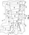
- FIG. 2 is a cross-sectional side view of a portion of a turbine section 24 of a gas turbine system 10 that may incorporate various embodiments disclosed herein.
- the turbine section 24 may include multiple turbine stages.
- the turbine section 24 may include a first turbine stage 30A, a second turbine stage 30B, and a third turbine stage 30C.
- the turbine section 24 may include more or less turbine stages as is necessary or desired.
- Each turbine stage 30A-30C may include, in serial flow order, a corresponding row of turbine nozzles (hereafter “nozzles”) 32A, 32B, and 32C and a corresponding row of turbine blades (hereafter “blades) 34A, 34B, and 34C axially spaced apart along the shaft 26 ( FIG. 1 ).
- nozzles turbine nozzles
- blades turbine blades
- Each of the nozzles 32A-32C remains stationary relative to the blades 34A-34C during operation of the gas turbine system 10.
- Each of the rows of nozzles 32B, 32C is respectively coupled to or formed integrally with a corresponding diaphragm 42B, 42C.
- Turbine shroud 44A, turbine shroud 44B, and turbine shroud 44C circumferentially enclose the corresponding row of blades 34A-34C.
- a casing or shell 36 circumferentially surrounds each stage 30A-30C of the nozzles 32A-32C and blades 34A-34C.
- the nozzles 32A-32C and blades 34A-34C extract kinetic and/or thermal energy from the combustion gases 22. This energy extraction drives the shaft 26.
- the combustion gases 22 then exit the turbine section 24 and the gas turbine system 10.
- a portion of the compressed air 16 may be used as a cooling fluid for cooling the various components of the turbine section 24 including, inter alia, the nozzles 32A-32C and blades 34A-34C.
- FIG. 3 is an isometric view of a nozzle segment 46 including an integrated nozzle 32 and diaphragm 42 according to embodiments.
- the nozzle 32 and diaphragm 42 may be formed as a single unit using, for example, an additive manufacturing process.
- the nozzle 32 may include an inner side wall 48 (which also forms an upper wall of the diaphragm 42) and an outer side wall 50 radially spaced apart from the inner side wall 48.
- the nozzle 32 may include a pair of vanes 52 that extend in span from the inner side wall 48 to the outer side wall 50. This nozzle configuration is commonly referred to in the industry as a doublet.
- the nozzle 32 may have only one vane 52 (i.e., a singlet) or three (i.e., a triplet) or more vanes 52.
- the inner and the outer side walls 48, 50 of the nozzle 32 include various surfaces. More specifically, the inner side wall 48 includes a radially outer surface 54 and a radially inner surface 56 positioned radially inwardly from the radially outer surface 54. Similarly, the outer side wall 50 includes a radially inner surface 58 and a radially outer surface 60 oriented radially outwardly from the radially inner surface 58. The radially inner surface 58 of the outer side wall 50 and the radially outer surface 54 of the inner side wall 48 respectively define inner and outer radial flow boundaries for the combustion gases 22 flowing through the turbine section 24 ( FIG. 1 ).
- each vane 52 extends from the inner side wall 48 to the outer side wall 50 of the nozzle 32.
- the body of each vane 52 includes a leading edge 62, a trailing edge 64, a pressure side wall 66, and an opposing suction side wall 68 extending from the leading edge 62 to the trailing edge 64.
- a cooling fluid such as pressurized cooling air 70 bled off from the compressor section 12 of the turbine system 10 ( FIG. 1 ), may be routed into one or more internal cavities 72 formed within each vane 52.
- the cooling air 70 may be used to cool (e.g., through impingement cooling, convection cooling, film cooling, etc.) various internal and external portions of the vane 52.
- Various portions of a vane 52 of a nozzle 32 may be subject to high temperatures and high mechanical forces during operation of the turbine system 10 ( FIG. 1 ), which can lead to a reduction in the operational lifetime of the nozzle 32.
- the operational lifetime of the nozzle 32 may be increased, for example, by preferentially varying the thicknesses of various portions of the vanes 52 (e.g., thicker in regions subject to higher forces, thinner in regions subject to lower forces) and by providing a contour-following impingement plate 76 ( FIG. 4 ) within the vanes 52.
- FIG. 4 depicts a cross-sectional view of the vanes 52A, 52B of the nozzle 32 taken along line 4 - 4 in FIG. 3 .
- each vane 52A, 52B includes at least one internal cavity 72 configured to receive a flow of cooling air 70. Cooling air 70 is shown as flowing radially downward (i.e., into the page) into the cavities 72, although other flow directions may be used.
- the internal cavities 72 of the vanes 52A, 52B may have different configurations as shown (e.g., the wall thicknesses of the vanes 52A, 52B may be different) or may have a similar configuration. In the non-limiting example shown in FIG. 4 , the flow of cooling air 70 is directed radially downward into the internal cavities 72 toward the diaphragm 42 ( FIG. 3 ).
- the impingement plate 76 may extend continuously about the internal cavity 72 as shown, or may include a plurality of separate impingement plate sections. In general, the impingement plate 76 directs cooling air 70 from the internal cavity 72 of each vane 52, through a plurality of apertures 78 ( FIG. 5 ) formed through the impingement plate 76, into an impingement cavity 80. After entering the cavity 80, the cooling air 70 impinges against various interior wall(s) of the vane 52 (e.g., pressure side wall 66 and suction side wall 68 of the vane 52), providing impingement cooling. The cooling air 70 may be directed from the cavity 80 to other internal/external portions of the vane 52 to provide additional cooling to the vane 52.
- the thicknesses of one or more portions of the vane 52 may be preferentially varied in accordance with expected (or estimated) operational forces.
- the operational forces on the vane 52 may be determined, for example, via computer modeling, physical testing, or other suitable analysis techniques. This may include, for example, modeling and analyzing the operational forces using an engineering simulation tool, modifying one or more of the thicknesses, and rerunning the analysis.
- the pressure side wall 66 of the vane 52 has been formed with a substantially uniform thickness, since operational forces are expected to be relatively uniform along the length of the pressure side wall 66.
- a radially outward portion 86 of the suction side wall 68 (e.g., in the hi-c region) is formed with a thickness greater than that of a radially inward portion 88 of the suction side wall 68, since operational forces are expected to be greater at the radially outward portion 86 of the suction side wall 68.
- the thicknesses of one or more portions of the vane 52 is proportional to expected operational forces.
- the thickness of the suction side wall 68 in the hi-c area e.g., see FIG. 5
- the nominal wall thickness e.g., the thickness of the pressure-side wall 66
- the wall thickness of portions of the walls of the vane 52 may be in the range of 1.1 to 2.5 X the nominal wall thickness of the vane 52.
- the impingement plate 76 is configured to follow the contours of the interior walls of the vane 52.
- the impingement plate 76 is configured to follow the contours of the inner side walls 90, 92 of the pressure and suction side walls 66, 68 of the vane 52.
- the distance D between the impingement plate 76 and the interior walls of the vane 52 (and the impingement cooling provided via the impingement plate 76) can be more accurately controlled (e.g., as compared to impingement plate inserts).
- the distance D may be substantially constant throughout the vane 52 or may be variable (e.g., to selectively adjust the resultant impingement cooling).
- a set of support beams 94 may be provided to connect and separate the impingement plate 76 to/from the inner side walls 90, 92 of the pressure and suction side walls 66, 68.
- the support beams 94 provide several functions.
- the support beams 94 connect the impingement plate and provide structural support/stiffness for the pressure and suction side walls 66, 68, allowing the pressure and suction side walls 66, 68 of the vane 52 to be made thinner.
- the support beams 94 maintain and control the distance D between the impingement plate 76 and the inner side walls 90, 92 of the pressure and suction side walls 66, 68. With thinner walls, the cooling air 70 can more effectively cool the hot side of a vane 52.
- the vane 52 instead of having the vane 52 be 5.08 mm (0.2") thick, it can be made 2.54 mm (0.1") thick and the impingement plate 76 can be made 2.54 mm (0.1") thick.
- the resulting structure has a similar stiffness, but a better cooling effectiveness.
- the amount of cooling air 70 needed to cool the structure is reduced and the life of the structure may be extended. This also provides the ability to tune specific locations to be thinner or thicker than the average to address stress and oxidation concerns.
- the thickness T IP of the (62, 64, 66, 68) varies within the vane 52.
- the thickness T IP of the impingement plate 76 is inversely proportional to a thickness Tw ( FIG. 6 ) of an adjacent interior wall section.
- the impingement plate 76 is thicker adjacent a thinner interior wall section (e.g., to provide additional structural support) and thinner adjacent a thicker interior wall section.
- FIG. 7 depicts a cross-sectional view of the leading edge 62 of the vane 52 taken along line 7 - 7 in FIG. 4 .
- a radially outward section 96 of the leading edge wall 82 of the vane 52 may experience higher forces than a radially inward section 98 of the leading edge wall 82.
- the thickness of the leading edge wall 82 may be preferentially varied such that higher forces regions (e.g., the radially outward section 96) are thicker than lower force regions (the radially inward section 98).
- any impingement cooling provided to the inner side wall 112 of the leading edge wall 82 of the vane 52 via the impingement plate 76 may be required at the thickened section 96 of the leading edge wall 82.
- Such cooling may be provided, for example, by forming a channel 100 through the thickened section 96 of the leading edge wall 82, extending from the internal cavity 72 to the cavity 80.
- the channel 100 is fluidly coupled to the cavity 80, which is further fluidly coupled to a channel 102 formed through the inner side wall 48 of the nozzle 32.
- cooling air 70 passes out of the cavity 80 into an internal cavity 104 of the diaphragm 42 through the channel 102.
- the cooling air 70 entering the cavity 104 through the channel 102 may pressurize the cavity 104 (e.g., to prevent hot gasses from entering the cavity 104) and/or may provide cooling to the inner side wall 48 of the nozzle 32.
- Yet another channel 106 may be provided to fluidly couple the cavity 72 to the wheel space 108 of the turbine section 24 ( FIG. 1 ).
- the channel 106 may extend from the cavity 72 to the wheel space 108, for example, through the inner side wall 48 of the nozzle 32 and a side wall 110 of the diaphragm 42.
- the cooling air 70 flowing through the channel 106 may provide cooling to the inner side wall 48 of the nozzle 32 and the side wall 110 of the diaphragm 42, and/or may be used to pressurize the wheel space 108 to keep hot gasses from entering the wheel space 108.
- FIG. 8 depicts a cross-sectional view of the nozzle segment 46 taken from the leading edge 62 to the trailing edge 64 of a vane 52 according to embodiments. To this extent, FIG. 8 includes the features at the leading edge 62 of the vane 52 previously described above with regard to FIG. 7 .
- the impingement plate 76 follows the contours of the inner side wall 114 of the trailing edge wall 84 of the trailing edge 64 of the vane 52. Cooling air 70 passes through the plurality of apertures 78 formed in the impingement plate 76 and into the cavity 80, where the cooling air 70 impinges against the inner side wall 114 of the trailing edge wall 84, providing impingement cooling.
- the cavity 80 may be fluidly coupled to at least one of a trailing edge cooling circuit 116 and a channel 118 formed through the inner side wall 48 of the nozzle 32.
- cooling air 70 may pass out of the cavity 80 into the internal cavity 104 of the diaphragm 42 through the channel 118 and/or may pass out of the cavity 80 to the trailing edge cooling circuit 116.
- the cooling air 70 entering the cavity 104 through the channel 118 combines with the cooling air 70 entering the cavity 104 through the channel 102 to pressurize the cavity 104 (e.g., to prevent hot gasses from entering the cavity 104) and/or provide cooling to the inner side wall 48 of the nozzle 32.
- An additional channel 120 may be provided to fluidly couple the cavity 72 to the wheel space 108 of the turbine section 24 ( FIG. 1 ).
- the channel 120 may extend from the cavity 72 to the wheel space 108, for example, through the inner side wall 48 of the nozzle 32 and a side wall 122 of the diaphragm 42.
- the cooling air 70 flowing through the channel 120 may provide cooling to the inner side wall 48 of the nozzle 32 and the side wall 122 of the diaphragm 42, and/or be used to pressurize the wheel space 108 to keep hot gasses from entering the wheel space 108.
- the support beams 94 formed between the impingement plate 76 and the inner side walls 112, 114 of the leading and trailing edge walls 82, 84 provide structural support/stiffness for the leading and trailing edge walls 82, 84, which allows the leading and trailing edge walls 82, 84 of the vane 52 to be made thinner. Further, the support beams 94 maintain and control the separation between the impingement plate 76 and the inner side walls 112, 114 of the leading and trailing edge walls 82, 84.
- turbine nozzle segment 46 may also be applied to other components of a gas turbine system 10.
- some/all of the embodiments described herein may be applied to a turbine blade 34, shroud 44, or other component(s) of the turbine system 10.
- Various components and features of the nozzle segment 46 of the present disclosure may be formed using an additive manufacturing process.
- additive manufacturing enables the design and production of more customizable features (e.g., vanes 52 with optimized wall thicknesses, contour-following impingement plate 76, etc.) as well as more intricate features (e.g., support beams 94), to provide better aerodynamic and high temperature efficiencies.
- the size (e.g., diameter, length) of various channels (e.g., channels 100, 102, 106, 118, 120) within the vanes 52 and diaphragm 42 of the nozzle segment 46 can be customized/optimized to reduce flow losses and to increase cooling efficiencies.
- features such as the contour-following impingement plate 76 and the support beams 94 may be formed integrally with the walls of the vane 52.
- the operational lifetime of the nozzle 32 may be increased, for example, by preferentially varying the thicknesses of various portions (e.g., walls, impingement plate, etc.) of the vanes 52.
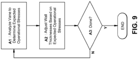
- a flow diagram of a process for optimizing wall thicknesses in a vane 52 is provided in FIG. 9 .
- an analysis is performed to determine the expected operational forces on various portions (e.g., pressure side wall 66, suction side wall 68, leading edge wall 82, trailing edge wall 84, etc.) of a vane 52.
- the analysis may be performed, for example, on a design of the vane 52, a physical model of the vane 52, or on the vane 52 itself.
- the design of the vane 52 is modified by preferentially varying the thicknesses of one or more walls of the vane 52 based on the expected operational forces. Processes A1 and A2 may be repeated as necessary on the updated design of the vane 52 (YES at process A3) to further optimize the wall thicknesses of the vane 52.
- additive manufacturing may include any process of producing an object through the successive layering of material rather than the removal of material, which is the case with conventional processes.
- Additive manufacturing can create complex geometries without the use of any sort of tools, molds or fixtures, and with little or no waste material. Instead of machining components from solid billets of plastic or metal, much of which is cut away and discarded, the only material used in additive manufacturing is what is required to shape the part.
- Additive manufacturing processes may include but are not limited to: 3D printing, rapid prototyping (RP), direct digital manufacturing (DDM), binder jetting, selective laser melting (SLM) and direct metal laser melting (DMLM). In the current setting, DMLM or SLM have been found advantageous.
- FIG. 10 shows a schematic/block view of an illustrative computerized additive manufacturing system 900 for generating an object 902.
- the system 900 is arranged for DMLM. It is understood that the general teachings of the disclosure are equally applicable to other forms of additive manufacturing.
- the object 902 is illustrated as a nozzle segment 46 ( FIGS. 3-7 ).
- the AM system 900 generally includes a computerized additive manufacturing (AM) control system 904 and an AM printer 906.
- the AM system 900 executes code 920 that includes a set of computer-executable instructions defining the object 902 to physically generate the object 902 using the AM printer 906.
- Each AM process may use different raw materials in the form of, for example, fine-grain powder, liquid (e.g., polymers), sheet, etc., a stock of which may be held in a chamber 910 of the AM printer 906.
- the nozzle segment 46 may be made of a metal or metal compound capable of withstanding the environment of a gas turbine system 10 ( FIG. 1 ).
- an applicator 912 may create a thin layer of raw material 914 spread out as the blank canvas on a build plate 915 of AM printer 906 from which each successive slice of the final object will be created.
- the applicator 912 may directly apply or print the next layer onto a previous layer as defined by code 920, e.g., where a metal binder jetting process is used.
- a laser or electron beam 916 fuses particles for each slice, as defined by code 920, but this may not be necessary where a quick setting liquid plastic/polymer is employed.
- Various parts of the AM printer 906 may move to accommodate the addition of each new layer, e.g., a build platform 918 may lower and/or chamber 910 and/or applicator 912 may rise after each layer.
- the AM control system 904 is shown implemented on a computer 930 as computer program code.
- the computer 930 is shown including a memory 932, a processor 934, an input/output (I/O) interface 936, and a bus 938. Further, the computer 930 is shown in communication with an external I/O device/resource 940 and a storage system 942.
- the processor 934 executes computer program code, such as the AM control system 904, that is stored in memory 932 and/or storage system 942 under instructions from code 920 representative of the object 902, described herein. While executing computer program code, the processor 934 can read and/or write data to/from memory 932, storage system 942, I/O device 940, and/or AM printer 906.
- the bus 938 provides a communication link between each of the components in the computer 930, and the I/O device 940 can comprise any device that enables a user to interact with computer 940 (e.g., keyboard, pointing device, display, etc.).
- the computer 930 is only representative of various possible combinations of hardware and software.
- the processor 934 may comprise a single processing unit, or be distributed across one or more processing units in one or more locations, e.g., on a client and server.
- the memory 932 and/or storage system 942 may reside at one or more physical locations.
- the memory 932 and/or storage system 942 can comprise any combination of various types of non-transitory computer readable storage medium including magnetic media, optical media, random access memory (RAM), read only memory (ROM), etc.
- the computer 930 can comprise any type of computing device such as a network server, a desktop computer, a laptop, a handheld device, a mobile phone, a pager, a personal data assistant, etc.
- Additive manufacturing processes begin with a non-transitory computer readable storage medium (e.g., memory 932, storage system 942, etc.) storing code 920 representative of the object 902.
- the code 920 may include a precisely defined 3D model of the object 902 and can be generated from any of a large variety of well-known computer aided design (CAD) software systems such as AutoCAD ® , TurboCAD ® , DesignCAD 3D Max, etc.
- CAD computer aided design
- the code 920 can take any now known or later developed file format.
- the code 920 may be in the Standard Tessellation Language (STL) which was created for stereolithography CAD programs of 3D Systems, or an additive manufacturing file (AMF), which is an American Society of Mechanical Engineers (ASME) standard that is an extensible markup-language (XML) based format designed to allow any CAD software to describe the shape and composition of any three-dimensional object to be fabricated on any AM printer.
- STL Standard Tessellation Language
- ASME American Society of Mechanical Engineers
- XML extensible markup-language
- the code 920 may be translated between different formats, converted into a set of data signals and transmitted, received as a set of data signals and converted to code, stored, etc., as necessary.
- the code 920 may be an input to system 900 and may come from a part designer, an intellectual property (IP) provider, a design company, the operator or owner of system 900, or from other sources.
- IP intellectual property
- the AM control system 904 executes the code 920, dividing the object 902 into a series of thin slices that it assembles using the AM printer 906 in successive layers of liquid, powder, sheet or other material.
- each layer is melted to the exact geometry defined by the code 920 and fused to the preceding layer.
- the object 902 may be exposed to any variety of finishing processes, e.g., those described herein for re-contouring or other minor machining, sealing, polishing, etc.
Landscapes
- Engineering & Computer Science (AREA)
- Mechanical Engineering (AREA)
- General Engineering & Computer Science (AREA)
- Chemical & Material Sciences (AREA)
- Combustion & Propulsion (AREA)
- Physics & Mathematics (AREA)
- Fluid Mechanics (AREA)
- Manufacturing & Machinery (AREA)
- Materials Engineering (AREA)
- Turbine Rotor Nozzle Sealing (AREA)
Claims (12)
- Schaufel (52) für ein Gasturbinentriebwerk, umfassend:einen inneren Hohlraum (72), der konfiguriert ist, um einen Strom von Kühlfluid aufzunehmen;eine Wand (62, 64, 66, 68) mit variabler Dicke, die an den inneren Hohlraum (72) angrenzt; undeine Aufprallplatte (76), die die Wand (62, 64, 66, 68) mit variabler Dicke von dem inneren Hohlraum (72) trennt, wobei die Aufprallplatte (76) eine Vielzahl von Öffnungen (78) einschließt, zum Leiten des Kühlfluids in einen Aufprallhohlraum (80) und gegen die Wand (62, 64, 66, 68) mit variabler Dicke, wobei die Aufprallplatte (76) konfiguriert ist, um einer Kontur der Wand (62, 64, 66, 68) mit variabler Dicke zu folgen;dadurch gekennzeichnet, dass die Aufprallplatte (76) eine variable Dicke (TIP) aufweist, wobei die Dicke (TIP) jedes Abschnitts der Aufprallplatte (76) derart umgekehrt proportional zu einer Dicke (Tw) eines angrenzenden Abschnitts der Wand (62, 64, 66, 68) mit variabler Dicke ist, dass die Aufprallplatte (76) angrenzend an einen dünneren Abschnitt der Wand (62, 64, 66, 68) mit variabler Dicke dicker und angrenzend an einen dickeren Abschnitt der Wand (62, 64, 66, 68) mit variabler Dicke dünner ist.
- Schaufel (52) nach Anspruch 1, wobei die Schaufel (52) eine Schaufel (52a, 52b) einer Düse (32) in einem Gasturbinensystem (10) umfasst.
- Schaufel (52) nach Anspruch 1, ferner umfassend eine Vielzahl von Stützbalken (94) zwischen der Aufprallplatte (76) und der Wand (62, 64, 66, 68) mit variabler Dicke.
- Schaufel (52) nach Anspruch 3, wobei die Vielzahl von Stützbalken (94) konfiguriert sind, um die Aufprallplatte (76) mit der Wand (62, 64, 66, 68) mit variabler Dicke zu verbinden, eine Trennung der Aufprallplatte (76) von der Wand (62, 64, 66, 68) mit variabler Dicke zu steuern und der Wand (62, 64, 66, 68) mit variabler Dicke eine strukturelle Unterstützung bereitzustellen.
- Schaufel (52) nach Anspruch 1, wobei die Wand (62, 64, 66, 68) mit variabler Dicke eine oder mehrere einer Vorderkantenwand (62) der Schaufel (52), einer Hinterkantenwand (64) der Schaufel (52), einer druckseitigen Wand (66) der Schaufel (52) und einer saugseitigen Wand (68) der Schaufel (52) umfasst.
- Schaufel (52) nach Anspruch 1, wobei die Dicke der Wand (62, 64, 66, 68) mit variabler Dicke gemäß zu erwartenden Betriebskräften auf die Schaufel (52) variiert.
- Schaufel (52) nach Anspruch 6, wobei die Dicke der Wand (62, 64, 66, 68) mit variabler Dicke in mindestens einem Abschnitt das 1,1- bis 2,5-fache einer Wanddicke der Schaufel (52) in einem anderen Abschnitt beträgt.
- Schaufel (52) nach Anspruch 1, die ferner einen Kühlkanal (100) einschließt, der in einem verdickten Bereich (96) der Schaufel (52) ausgebildet ist, wobei der Kühlkanal (100) mit dem inneren Hohlraum (72) fluidisch gekoppelt ist.
- Schaufel (52) nach Anspruch 1, die ferner einen Kanal (102) zum fluidischen Koppeln des Aufprallhohlraums (80) mit mindestens einem von einem inneren Hohlraum (104) einer Membran (42) und einem Hinterkantenkühlkreis (116) der Schaufel (52) einschließt.
- Schaufel (52) nach Anspruch 9, wobei die Schaufel (52) einstückig mit der Membran (42) ausgebildet ist.
- Schaufel (52) nach Anspruch 1, die ferner mindestens einen Kanal (106, 120) einschließt, zum fluidischen Koppeln des inneren Hohlraums (72) mit einem Radraum (108) eines Gasturbinensystems (10).
- Düsensegment (46) für ein Gasturbinensystem (10), umfassend eine integrierte Düse (32) und eine Membran (42), wobei die Düse (32) mindestens eine Schaufel (52) nach einem der vorstehenden Ansprüche einschließt.
Applications Claiming Priority (2)
| Application Number | Priority Date | Filing Date | Title |
|---|---|---|---|
| US16/575,785 US11162432B2 (en) | 2019-09-19 | 2019-09-19 | Integrated nozzle and diaphragm with optimized internal vane thickness |
| PCT/US2020/049896 WO2021055200A1 (en) | 2019-09-19 | 2020-09-09 | Integrated nozzle and diaphragm with optimized internal vane thickness |
Publications (2)
| Publication Number | Publication Date |
|---|---|
| EP4031750A1 EP4031750A1 (de) | 2022-07-27 |
| EP4031750B1 true EP4031750B1 (de) | 2024-10-30 |
Family
ID=72614017
Family Applications (1)
| Application Number | Title | Priority Date | Filing Date |
|---|---|---|---|
| EP20776018.2A Active EP4031750B1 (de) | 2019-09-19 | 2020-09-09 | Leitapparat mit integriertem deckband mit optimierter leitschaufelwanddicke |
Country Status (5)
| Country | Link |
|---|---|
| US (1) | US11162432B2 (de) |
| EP (1) | EP4031750B1 (de) |
| JP (1) | JP7646634B2 (de) |
| CN (1) | CN114341465B (de) |
| WO (1) | WO2021055200A1 (de) |
Families Citing this family (3)
| Publication number | Priority date | Publication date | Assignee | Title |
|---|---|---|---|---|
| KR20240099443A (ko) * | 2021-12-28 | 2024-06-28 | 미츠비시 파워 가부시키가이샤 | 동익, 및 이것을 구비하고 있는 가스 터빈 |
| US20250327406A1 (en) * | 2022-11-03 | 2025-10-23 | General Electric Company | Turbine nozzle or blade with impingement cooling structure having thermal flex elements |
| US12448896B2 (en) * | 2023-08-21 | 2025-10-21 | Rtx Corporation | Localized thickening ply reinforcement within ceramic matrix composite airfoil cavity |
Family Cites Families (19)
| Publication number | Priority date | Publication date | Assignee | Title |
|---|---|---|---|---|
| JPS5390509A (en) * | 1977-01-20 | 1978-08-09 | Koukuu Uchiyuu Gijiyutsu Kenki | Structure of air cooled turbine blade |
| GB2051964B (en) | 1979-06-30 | 1983-01-12 | Rolls Royce | Turbine blade |
| GB9901218D0 (en) * | 1999-01-21 | 1999-03-10 | Rolls Royce Plc | Cooled aerofoil for a gas turbine engine |
| US6142734A (en) | 1999-04-06 | 2000-11-07 | General Electric Company | Internally grooved turbine wall |
| US6325593B1 (en) * | 2000-02-18 | 2001-12-04 | General Electric Company | Ceramic turbine airfoils with cooled trailing edge blocks |
| JP3782637B2 (ja) | 2000-03-08 | 2006-06-07 | 三菱重工業株式会社 | ガスタービン冷却静翼 |
| US6428270B1 (en) | 2000-09-15 | 2002-08-06 | General Electric Company | Stage 3 bucket shank bypass holes and related method |
| US7008178B2 (en) * | 2003-12-17 | 2006-03-07 | General Electric Company | Inboard cooled nozzle doublet |
| US8257035B2 (en) | 2007-12-05 | 2012-09-04 | Siemens Energy, Inc. | Turbine vane for a gas turbine engine |
| US20120070302A1 (en) * | 2010-09-20 | 2012-03-22 | Ching-Pang Lee | Turbine airfoil vane with an impingement insert having a plurality of impingement nozzles |
| EP2573325A1 (de) * | 2011-09-23 | 2013-03-27 | Siemens Aktiengesellschaft | Aufprallkühlung von Turbinenschaufeln oder -flügeln |
| US20130104567A1 (en) * | 2011-10-31 | 2013-05-02 | Douglas Gerard Konitzer | Method and apparatus for cooling gas turbine rotor blades |
| WO2013163150A1 (en) | 2012-04-23 | 2013-10-31 | General Electric Company | Turbine airfoil with local wall thickness control |
| US9470095B2 (en) | 2012-04-24 | 2016-10-18 | United Technologies Corporation | Airfoil having internal lattice network |
| US10392942B2 (en) | 2014-11-26 | 2019-08-27 | Ansaldo Energia Ip Uk Limited | Tapered cooling channel for airfoil |
| EP3325774B1 (de) * | 2015-08-28 | 2019-06-19 | Siemens Aktiengesellschaft | Turbinenschaufel mit interner prallkühlfunktion |
| US10408073B2 (en) | 2016-01-20 | 2019-09-10 | General Electric Company | Cooled CMC wall contouring |
| US10519779B2 (en) | 2016-03-16 | 2019-12-31 | General Electric Company | Radial CMC wall thickness variation for stress response |
| US10436037B2 (en) | 2016-07-22 | 2019-10-08 | General Electric Company | Blade with parallel corrugated surfaces on inner and outer surfaces |
-
2019
- 2019-09-19 US US16/575,785 patent/US11162432B2/en active Active
-
2020
- 2020-09-09 JP JP2022515819A patent/JP7646634B2/ja active Active
- 2020-09-09 CN CN202080062580.0A patent/CN114341465B/zh active Active
- 2020-09-09 WO PCT/US2020/049896 patent/WO2021055200A1/en not_active Ceased
- 2020-09-09 EP EP20776018.2A patent/EP4031750B1/de active Active
Also Published As
| Publication number | Publication date |
|---|---|
| WO2021055200A1 (en) | 2021-03-25 |
| CN114341465A (zh) | 2022-04-12 |
| JP2022549074A (ja) | 2022-11-24 |
| JP7646634B2 (ja) | 2025-03-17 |
| EP4031750A1 (de) | 2022-07-27 |
| US11162432B2 (en) | 2021-11-02 |
| CN114341465B (zh) | 2025-06-10 |
| US20210087979A1 (en) | 2021-03-25 |
Similar Documents
| Publication | Publication Date | Title |
|---|---|---|
| US10436037B2 (en) | Blade with parallel corrugated surfaces on inner and outer surfaces | |
| US10774658B2 (en) | Interior cooling configurations in turbine blades and methods of manufacture relating thereto | |
| US20170334188A1 (en) | Hot gas path component and methods of manufacture | |
| EP4031750B1 (de) | Leitapparat mit integriertem deckband mit optimierter leitschaufelwanddicke | |
| JP7346254B2 (ja) | 複数のノズルおよびベンチュリを含む高温ガス経路構成要素 | |
| US20180016917A1 (en) | Turbomachine component having impingement heat transfer feature, related turbomachine and storage medium | |
| US10830050B2 (en) | Unitary body turbine shrouds including structural breakdown and collapsible features | |
| US20240209738A1 (en) | Turbomachine cooling trench | |
| US10927693B2 (en) | Unitary body turbine shroud for turbine systems | |
| US10822986B2 (en) | Unitary body turbine shrouds including internal cooling passages | |
| CN113153440B (zh) | 增材制造的具有带格栅支撑结构的中空安装架的涡轮转子叶片根部 | |
| US20200392853A1 (en) | Hot gas path component with metering structure including converging-diverging passage portions | |
| US20250327406A1 (en) | Turbine nozzle or blade with impingement cooling structure having thermal flex elements | |
| EP3660270B1 (de) | Gekühltes schaufelblatt mit düsen und venturi-elementen | |
| EP3825523B1 (de) | Integrales turbinendeckband mit geformten kugelstrahlgittern und entsprechendes turbinensystem | |
| US12497897B1 (en) | Airfoil component for turbomachine component with platform cooling using airfoil coolant | |
| JP2025165888A (ja) | 冷却回路を有するタービンシュラウドおよびターボ機械 |
Legal Events
| Date | Code | Title | Description |
|---|---|---|---|
| STAA | Information on the status of an ep patent application or granted ep patent |
Free format text: STATUS: UNKNOWN |
|
| STAA | Information on the status of an ep patent application or granted ep patent |
Free format text: STATUS: THE INTERNATIONAL PUBLICATION HAS BEEN MADE |
|
| PUAI | Public reference made under article 153(3) epc to a published international application that has entered the european phase |
Free format text: ORIGINAL CODE: 0009012 |
|
| STAA | Information on the status of an ep patent application or granted ep patent |
Free format text: STATUS: REQUEST FOR EXAMINATION WAS MADE |
|
| 17P | Request for examination filed |
Effective date: 20220303 |
|
| AK | Designated contracting states |
Kind code of ref document: A1 Designated state(s): AL AT BE BG CH CY CZ DE DK EE ES FI FR GB GR HR HU IE IS IT LI LT LU LV MC MK MT NL NO PL PT RO RS SE SI SK SM TR |
|
| DAV | Request for validation of the european patent (deleted) | ||
| DAX | Request for extension of the european patent (deleted) | ||
| RAP1 | Party data changed (applicant data changed or rights of an application transferred) |
Owner name: GENERAL ELECTRIC TECHNOLOGY GMBH |
|
| GRAP | Despatch of communication of intention to grant a patent |
Free format text: ORIGINAL CODE: EPIDOSNIGR1 |
|
| STAA | Information on the status of an ep patent application or granted ep patent |
Free format text: STATUS: GRANT OF PATENT IS INTENDED |
|
| INTG | Intention to grant announced |
Effective date: 20240328 |
|
| GRAS | Grant fee paid |
Free format text: ORIGINAL CODE: EPIDOSNIGR3 |
|
| GRAA | (expected) grant |
Free format text: ORIGINAL CODE: 0009210 |
|
| STAA | Information on the status of an ep patent application or granted ep patent |
Free format text: STATUS: THE PATENT HAS BEEN GRANTED |
|
| AK | Designated contracting states |
Kind code of ref document: B1 Designated state(s): AL AT BE BG CH CY CZ DE DK EE ES FI FR GB GR HR HU IE IS IT LI LT LU LV MC MK MT NL NO PL PT RO RS SE SI SK SM TR |
|
| REG | Reference to a national code |
Ref country code: GB Ref legal event code: FG4D |
|
| REG | Reference to a national code |
Ref country code: CH Ref legal event code: EP |
|
| REG | Reference to a national code |
Ref country code: IE Ref legal event code: FG4D |
|
| REG | Reference to a national code |
Ref country code: DE Ref legal event code: R096 Ref document number: 602020040369 Country of ref document: DE |
|
| REG | Reference to a national code |
Ref country code: LT Ref legal event code: MG9D |
|
| REG | Reference to a national code |
Ref country code: NL Ref legal event code: MP Effective date: 20241030 |
|
| PG25 | Lapsed in a contracting state [announced via postgrant information from national office to epo] |
Ref country code: IS Free format text: LAPSE BECAUSE OF FAILURE TO SUBMIT A TRANSLATION OF THE DESCRIPTION OR TO PAY THE FEE WITHIN THE PRESCRIBED TIME-LIMIT Effective date: 20250228 Ref country code: PT Free format text: LAPSE BECAUSE OF FAILURE TO SUBMIT A TRANSLATION OF THE DESCRIPTION OR TO PAY THE FEE WITHIN THE PRESCRIBED TIME-LIMIT Effective date: 20250228 Ref country code: HR Free format text: LAPSE BECAUSE OF FAILURE TO SUBMIT A TRANSLATION OF THE DESCRIPTION OR TO PAY THE FEE WITHIN THE PRESCRIBED TIME-LIMIT Effective date: 20241030 |
|
| PG25 | Lapsed in a contracting state [announced via postgrant information from national office to epo] |
Ref country code: FI Free format text: LAPSE BECAUSE OF FAILURE TO SUBMIT A TRANSLATION OF THE DESCRIPTION OR TO PAY THE FEE WITHIN THE PRESCRIBED TIME-LIMIT Effective date: 20241030 Ref country code: NL Free format text: LAPSE BECAUSE OF FAILURE TO SUBMIT A TRANSLATION OF THE DESCRIPTION OR TO PAY THE FEE WITHIN THE PRESCRIBED TIME-LIMIT Effective date: 20241030 |
|
| REG | Reference to a national code |
Ref country code: AT Ref legal event code: MK05 Ref document number: 1737045 Country of ref document: AT Kind code of ref document: T Effective date: 20241030 |
|
| PG25 | Lapsed in a contracting state [announced via postgrant information from national office to epo] |
Ref country code: BG Free format text: LAPSE BECAUSE OF FAILURE TO SUBMIT A TRANSLATION OF THE DESCRIPTION OR TO PAY THE FEE WITHIN THE PRESCRIBED TIME-LIMIT Effective date: 20241030 |
|
| PG25 | Lapsed in a contracting state [announced via postgrant information from national office to epo] |
Ref country code: ES Free format text: LAPSE BECAUSE OF FAILURE TO SUBMIT A TRANSLATION OF THE DESCRIPTION OR TO PAY THE FEE WITHIN THE PRESCRIBED TIME-LIMIT Effective date: 20241030 |
|
| PG25 | Lapsed in a contracting state [announced via postgrant information from national office to epo] |
Ref country code: NO Free format text: LAPSE BECAUSE OF FAILURE TO SUBMIT A TRANSLATION OF THE DESCRIPTION OR TO PAY THE FEE WITHIN THE PRESCRIBED TIME-LIMIT Effective date: 20250130 |
|
| PG25 | Lapsed in a contracting state [announced via postgrant information from national office to epo] |
Ref country code: LV Free format text: LAPSE BECAUSE OF FAILURE TO SUBMIT A TRANSLATION OF THE DESCRIPTION OR TO PAY THE FEE WITHIN THE PRESCRIBED TIME-LIMIT Effective date: 20241030 Ref country code: GR Free format text: LAPSE BECAUSE OF FAILURE TO SUBMIT A TRANSLATION OF THE DESCRIPTION OR TO PAY THE FEE WITHIN THE PRESCRIBED TIME-LIMIT Effective date: 20250131 Ref country code: AT Free format text: LAPSE BECAUSE OF FAILURE TO SUBMIT A TRANSLATION OF THE DESCRIPTION OR TO PAY THE FEE WITHIN THE PRESCRIBED TIME-LIMIT Effective date: 20241030 |
|
| PG25 | Lapsed in a contracting state [announced via postgrant information from national office to epo] |
Ref country code: PL Free format text: LAPSE BECAUSE OF FAILURE TO SUBMIT A TRANSLATION OF THE DESCRIPTION OR TO PAY THE FEE WITHIN THE PRESCRIBED TIME-LIMIT Effective date: 20241030 |
|
| PG25 | Lapsed in a contracting state [announced via postgrant information from national office to epo] |
Ref country code: RS Free format text: LAPSE BECAUSE OF FAILURE TO SUBMIT A TRANSLATION OF THE DESCRIPTION OR TO PAY THE FEE WITHIN THE PRESCRIBED TIME-LIMIT Effective date: 20250130 |
|
| PG25 | Lapsed in a contracting state [announced via postgrant information from national office to epo] |
Ref country code: SM Free format text: LAPSE BECAUSE OF FAILURE TO SUBMIT A TRANSLATION OF THE DESCRIPTION OR TO PAY THE FEE WITHIN THE PRESCRIBED TIME-LIMIT Effective date: 20241030 |
|
| PG25 | Lapsed in a contracting state [announced via postgrant information from national office to epo] |
Ref country code: DK Free format text: LAPSE BECAUSE OF FAILURE TO SUBMIT A TRANSLATION OF THE DESCRIPTION OR TO PAY THE FEE WITHIN THE PRESCRIBED TIME-LIMIT Effective date: 20241030 |
|
| PG25 | Lapsed in a contracting state [announced via postgrant information from national office to epo] |
Ref country code: EE Free format text: LAPSE BECAUSE OF FAILURE TO SUBMIT A TRANSLATION OF THE DESCRIPTION OR TO PAY THE FEE WITHIN THE PRESCRIBED TIME-LIMIT Effective date: 20241030 |
|
| PG25 | Lapsed in a contracting state [announced via postgrant information from national office to epo] |
Ref country code: RO Free format text: LAPSE BECAUSE OF FAILURE TO SUBMIT A TRANSLATION OF THE DESCRIPTION OR TO PAY THE FEE WITHIN THE PRESCRIBED TIME-LIMIT Effective date: 20241030 |
|
| PG25 | Lapsed in a contracting state [announced via postgrant information from national office to epo] |
Ref country code: SK Free format text: LAPSE BECAUSE OF FAILURE TO SUBMIT A TRANSLATION OF THE DESCRIPTION OR TO PAY THE FEE WITHIN THE PRESCRIBED TIME-LIMIT Effective date: 20241030 |
|
| PG25 | Lapsed in a contracting state [announced via postgrant information from national office to epo] |
Ref country code: CZ Free format text: LAPSE BECAUSE OF FAILURE TO SUBMIT A TRANSLATION OF THE DESCRIPTION OR TO PAY THE FEE WITHIN THE PRESCRIBED TIME-LIMIT Effective date: 20241030 |
|
| REG | Reference to a national code |
Ref country code: DE Ref legal event code: R097 Ref document number: 602020040369 Country of ref document: DE |
|
| PLBE | No opposition filed within time limit |
Free format text: ORIGINAL CODE: 0009261 |
|
| STAA | Information on the status of an ep patent application or granted ep patent |
Free format text: STATUS: NO OPPOSITION FILED WITHIN TIME LIMIT |
|
| PG25 | Lapsed in a contracting state [announced via postgrant information from national office to epo] |
Ref country code: SE Free format text: LAPSE BECAUSE OF FAILURE TO SUBMIT A TRANSLATION OF THE DESCRIPTION OR TO PAY THE FEE WITHIN THE PRESCRIBED TIME-LIMIT Effective date: 20241030 |
|
| RAP4 | Party data changed (patent owner data changed or rights of a patent transferred) |
Owner name: GE VERNOVA TECHNOLOGY GMBH |
|
| REG | Reference to a national code |
Ref country code: CH Ref legal event code: U11 Free format text: ST27 STATUS EVENT CODE: U-0-0-U10-U11 (AS PROVIDED BY THE NATIONAL OFFICE) Effective date: 20251001 |
|
| 26N | No opposition filed |
Effective date: 20250731 |
|
| PGFP | Annual fee paid to national office [announced via postgrant information from national office to epo] |
Ref country code: DE Payment date: 20250820 Year of fee payment: 6 |
|
| PGFP | Annual fee paid to national office [announced via postgrant information from national office to epo] |
Ref country code: IT Payment date: 20250820 Year of fee payment: 6 |
|
| PGFP | Annual fee paid to national office [announced via postgrant information from national office to epo] |
Ref country code: GB Payment date: 20250822 Year of fee payment: 6 |
|
| PGFP | Annual fee paid to national office [announced via postgrant information from national office to epo] |
Ref country code: FR Payment date: 20250820 Year of fee payment: 6 |
|
| PGFP | Annual fee paid to national office [announced via postgrant information from national office to epo] |
Ref country code: CH Payment date: 20251001 Year of fee payment: 6 |