EP3333023A1 - Mounting structure of vehicle periphery monitoring device - Google Patents
Mounting structure of vehicle periphery monitoring device Download PDFInfo
- Publication number
- EP3333023A1 EP3333023A1 EP17206198.8A EP17206198A EP3333023A1 EP 3333023 A1 EP3333023 A1 EP 3333023A1 EP 17206198 A EP17206198 A EP 17206198A EP 3333023 A1 EP3333023 A1 EP 3333023A1
- Authority
- EP
- European Patent Office
- Prior art keywords
- vehicle
- monitoring device
- periphery monitoring
- width direction
- sensor
- Prior art date
- Legal status (The legal status is an assumption and is not a legal conclusion. Google has not performed a legal analysis and makes no representation as to the accuracy of the status listed.)
- Granted
Links
Images




Classifications
-
- B—PERFORMING OPERATIONS; TRANSPORTING
- B60—VEHICLES IN GENERAL
- B60R—VEHICLES, VEHICLE FITTINGS, OR VEHICLE PARTS, NOT OTHERWISE PROVIDED FOR
- B60R19/00—Wheel guards; Radiator guards, e.g. grilles; Obstruction removers; Fittings damping bouncing force in collisions
- B60R19/02—Bumpers, i.e. impact receiving or absorbing members for protecting vehicles or fending off blows from other vehicles or objects
- B60R19/48—Bumpers, i.e. impact receiving or absorbing members for protecting vehicles or fending off blows from other vehicles or objects combined with, or convertible into, other devices or objects, e.g. bumpers combined with road brushes, bumpers convertible into beds
- B60R19/483—Bumpers, i.e. impact receiving or absorbing members for protecting vehicles or fending off blows from other vehicles or objects combined with, or convertible into, other devices or objects, e.g. bumpers combined with road brushes, bumpers convertible into beds with obstacle sensors of electric or electronic type
-
- B—PERFORMING OPERATIONS; TRANSPORTING
- B60—VEHICLES IN GENERAL
- B60Q—ARRANGEMENT OF SIGNALLING OR LIGHTING DEVICES, THE MOUNTING OR SUPPORTING THEREOF OR CIRCUITS THEREFOR, FOR VEHICLES IN GENERAL
- B60Q1/00—Arrangement of optical signalling or lighting devices, the mounting or supporting thereof or circuits therefor
- B60Q1/0017—Devices integrating an element dedicated to another function
- B60Q1/0023—Devices integrating an element dedicated to another function the element being a sensor, e.g. distance sensor, camera
-
- B—PERFORMING OPERATIONS; TRANSPORTING
- B60—VEHICLES IN GENERAL
- B60Q—ARRANGEMENT OF SIGNALLING OR LIGHTING DEVICES, THE MOUNTING OR SUPPORTING THEREOF OR CIRCUITS THEREFOR, FOR VEHICLES IN GENERAL
- B60Q1/00—Arrangement of optical signalling or lighting devices, the mounting or supporting thereof or circuits therefor
- B60Q1/02—Arrangement of optical signalling or lighting devices, the mounting or supporting thereof or circuits therefor the devices being primarily intended to illuminate the way ahead or to illuminate other areas of way or environments
- B60Q1/04—Arrangement of optical signalling or lighting devices, the mounting or supporting thereof or circuits therefor the devices being primarily intended to illuminate the way ahead or to illuminate other areas of way or environments the devices being headlights
- B60Q1/0408—Arrangement of optical signalling or lighting devices, the mounting or supporting thereof or circuits therefor the devices being primarily intended to illuminate the way ahead or to illuminate other areas of way or environments the devices being headlights built into the vehicle body, e.g. details concerning the mounting of the headlamps on the vehicle body
-
- B—PERFORMING OPERATIONS; TRANSPORTING
- B60—VEHICLES IN GENERAL
- B60R—VEHICLES, VEHICLE FITTINGS, OR VEHICLE PARTS, NOT OTHERWISE PROVIDED FOR
- B60R19/00—Wheel guards; Radiator guards, e.g. grilles; Obstruction removers; Fittings damping bouncing force in collisions
- B60R19/02—Bumpers, i.e. impact receiving or absorbing members for protecting vehicles or fending off blows from other vehicles or objects
- B60R19/48—Bumpers, i.e. impact receiving or absorbing members for protecting vehicles or fending off blows from other vehicles or objects combined with, or convertible into, other devices or objects, e.g. bumpers combined with road brushes, bumpers convertible into beds
- B60R19/50—Bumpers, i.e. impact receiving or absorbing members for protecting vehicles or fending off blows from other vehicles or objects combined with, or convertible into, other devices or objects, e.g. bumpers combined with road brushes, bumpers convertible into beds with lights or registration plates
-
- B—PERFORMING OPERATIONS; TRANSPORTING
- B60—VEHICLES IN GENERAL
- B60R—VEHICLES, VEHICLE FITTINGS, OR VEHICLE PARTS, NOT OTHERWISE PROVIDED FOR
- B60R21/00—Arrangements or fittings on vehicles for protecting or preventing injuries to occupants or pedestrians in case of accidents or other traffic risks
- B60R21/34—Protecting non-occupants of a vehicle, e.g. pedestrians
-
- B—PERFORMING OPERATIONS; TRANSPORTING
- B60—VEHICLES IN GENERAL
- B60R—VEHICLES, VEHICLE FITTINGS, OR VEHICLE PARTS, NOT OTHERWISE PROVIDED FOR
- B60R19/00—Wheel guards; Radiator guards, e.g. grilles; Obstruction removers; Fittings damping bouncing force in collisions
- B60R19/02—Bumpers, i.e. impact receiving or absorbing members for protecting vehicles or fending off blows from other vehicles or objects
- B60R19/48—Bumpers, i.e. impact receiving or absorbing members for protecting vehicles or fending off blows from other vehicles or objects combined with, or convertible into, other devices or objects, e.g. bumpers combined with road brushes, bumpers convertible into beds
- B60R19/50—Bumpers, i.e. impact receiving or absorbing members for protecting vehicles or fending off blows from other vehicles or objects combined with, or convertible into, other devices or objects, e.g. bumpers combined with road brushes, bumpers convertible into beds with lights or registration plates
- B60R2019/505—Bumpers, i.e. impact receiving or absorbing members for protecting vehicles or fending off blows from other vehicles or objects combined with, or convertible into, other devices or objects, e.g. bumpers combined with road brushes, bumpers convertible into beds with lights or registration plates with lights
-
- B—PERFORMING OPERATIONS; TRANSPORTING
- B60—VEHICLES IN GENERAL
- B60R—VEHICLES, VEHICLE FITTINGS, OR VEHICLE PARTS, NOT OTHERWISE PROVIDED FOR
- B60R21/00—Arrangements or fittings on vehicles for protecting or preventing injuries to occupants or pedestrians in case of accidents or other traffic risks
- B60R2021/003—Arrangements or fittings on vehicles for protecting or preventing injuries to occupants or pedestrians in case of accidents or other traffic risks characterised by occupant or pedestian
- B60R2021/0039—Body parts of the occupant or pedestrian affected by the accident
- B60R2021/0053—Legs
-
- B—PERFORMING OPERATIONS; TRANSPORTING
- B60—VEHICLES IN GENERAL
- B60R—VEHICLES, VEHICLE FITTINGS, OR VEHICLE PARTS, NOT OTHERWISE PROVIDED FOR
- B60R21/00—Arrangements or fittings on vehicles for protecting or preventing injuries to occupants or pedestrians in case of accidents or other traffic risks
- B60R21/01—Electrical circuits for triggering passive safety arrangements, e.g. airbags, safety belt tighteners, in case of vehicle accidents or impending vehicle accidents
- B60R2021/01013—Means for detecting collision, impending collision or roll-over
- B60R2021/01027—Safing sensors
-
- G—PHYSICS
- G01—MEASURING; TESTING
- G01S—RADIO DIRECTION-FINDING; RADIO NAVIGATION; DETERMINING DISTANCE OR VELOCITY BY USE OF RADIO WAVES; LOCATING OR PRESENCE-DETECTING BY USE OF THE REFLECTION OR RERADIATION OF RADIO WAVES; ANALOGOUS ARRANGEMENTS USING OTHER WAVES
- G01S13/00—Systems using the reflection or reradiation of radio waves, e.g. radar systems; Analogous systems using reflection or reradiation of waves whose nature or wavelength is irrelevant or unspecified
- G01S13/88—Radar or analogous systems specially adapted for specific applications
- G01S13/93—Radar or analogous systems specially adapted for specific applications for anti-collision purposes
- G01S13/931—Radar or analogous systems specially adapted for specific applications for anti-collision purposes of land vehicles
- G01S2013/9327—Sensor installation details
- G01S2013/93275—Sensor installation details in the bumper area
Definitions
- the present disclosure relates to a mounting structure of a vehicle periphery monitoring device.
- a sensor that detects an object of a vehicle periphery (a vehicle periphery monitoring device) is mounted not on a vehicle body skeletal member, but on an inner surface of a bumper cover or on a bumper retainer that are made of a resin.
- a sensor that detects an object of a vehicle periphery (a vehicle periphery monitoring device) is mounted not on a vehicle body skeletal member, but on an inner surface of a bumper cover or on a bumper retainer that are made of a resin.
- the present disclosure obtains a mounting structure of a vehicle periphery monitoring device that can reduce a load on a pedestrian received from a vehicle during a collision between the vehicle and the pedestrian, and in which it is difficult for a misalignment to occur in a position or angle of the vehicle periphery monitoring device.
- a first aspect of the present disclosure is a mounting structure of a vehicle periphery monitoring device, including (i) a front bumper reinforcement that extends along a vehicle width direction and is disposed in a frontward end section at a vehicle body of a vehicle, (ii) a headlamp having a lamp housing, a light source being housed in the lamp housing, the headlamp being disposed further in a vehicle body upward direction than the front bumper reinforcement and at an outward end section in the vehicle width direction of the vehicle, (iii) a vehicle component disposed further in a vehicle body downward direction than the headlamp, and (iv) a vehicle periphery monitoring device disposed further in a vehicle body downward direction than a lower surface of the lamp housing, the vehicle periphery monitoring device separated by a first gap in the vehicle width direction from an outward end surface in the vehicle width direction of the front bumper reinforcement, and being separated by a second gap in a vehicle body vertical direction from an upward end surface of the vehicle component, the vehicle periphery monitoring device detecting an object
- a vehicle periphery monitoring device that detects an object frontwards and outwards in a vehicle width direction of a vehicle, is disposed further in a vehicle body downward direction than a lower surface of a lamp housing and is separated by the first gap in the vehicle width direction from the outward end surface in the vehicle width direction of a front bumper reinforcement, and being separated by the second gap in a vehicle body vertical direction from the upward end surface of a vehicle component.
- a second aspect of the present disclosure is the mounting structure of the vehicle periphery monitoring device according to the above-described first aspect, wherein an installation angle in planar view of the vehicle periphery monitoring device is assumed to be an angle at which a detecting region in which the object is detected does not interfere with a turning region of a front wheel.
- an installation angle in planar view of the vehicle periphery monitoring device is assumed to be an angle at which a detecting region in which the object is detected does not interfere with the turning region of a front wheel. Therefore, it is prevented that the front wheel is misdetected as the object by the vehicle periphery monitoring device.
- a third aspect of the present disclosure is the mounting structure of the vehicle periphery monitoring device according to the above-described first and second aspects, wherein the vehicle periphery monitoring device is attached to a bracket, the bracket suspends downwardly in the vehicle vertical direction from the lower surface of the lamp housing.
- the vehicle periphery monitoring device is attached to the bracket that suspends from the lower surface of the lamp housing, it is more difficult for a misalignment to occur in a position or angle of the vehicle periphery monitoring device, compared to in a configuration where the vehicle periphery monitoring device is provided on an inner surface of a bumper cover, for example.
- a load on a pedestrian received from a vehicle during a collision between the vehicle and the pedestrian can be reduced.
- an arrow UP, an arrow FR, and an arrow RH appropriately indicated in each of the drawings are assumed to be, respectively, a vehicle upward direction, a vehicle frontward direction, and a vehicle rightward direction.
- arrow UP, an arrow FR, and an arrow RH appropriately indicated in each of the drawings are assumed to be, respectively, a vehicle upward direction, a vehicle frontward direction, and a vehicle rightward direction.
- directions of up/down, front/rear, and left/right are described, these are assumed to indicate up/down in a vehicle vertical direction, front/rear in a vehicle front-rear direction, and left/right in a vehicle left-right direction (vehicle width direction), unless otherwise specifically stated.
- a mounting structure 10 of a sensor 30 serving as a vehicle periphery monitoring device includes a front bumper reinforcement 14, made of a metal, which is extended in the vehicle width direction to be disposed in a frontward end section of a vehicle 12.
- the front bumper reinforcement 14 is installed, via a crash box 16 (refer to Fig. 5 ), in front end sections of a left/right pair of front side members (illustration of which is omitted), and is formed in a rectangular closed cross-sectional shape in a cross-sectional view orthogonal to the vehicle width direction.
- the mounting structure 10 includes a headlamp 20 disposed further in a vehicle body upward direction than the front bumper reinforcement 14 and at an outward end section in the vehicle width direction of the vehicle 12.
- the headlamp 20 has a lamp housing 22 formed in a casing shape by a resin material, and an unillustrated light source, reflector, lens, and so on, are housed in the lamp housing 22.
- the lamp housing 22 is hermetically sealed and has a waterproof property.
- a front wall of the lamp housing 22 is configured as a transparent outer lens 23.
- a resin material resistant to damage such as cracking is adopted in the outer lens 23, and the outer lens 23 undergoes the likes of a surface treatment having an ultraviolet absorbing function (ultraviolet degradation resistance) or a surface treatment inhibiting scratching.
- This outer lens 23 is configured so as to be exposed from a space surrounded by an unillustrated front bumper cover, front fender panel, and closed-state engine hood, and so as to transmit light that has been generated from the light source to be reflected by the reflector and made into a light beam by the lens. This results in a configuration whereby a certain region on a vehicle body frontward of the vehicle 12 is illuminated.
- the mounting structure 10 includes a control device (ECU) 36, serving as a vehicle component, which is disposed further in a vehicle body downward direction than the headlamp 20 (sensor 30).
- the control device 36 is housed in a cover body 38, made of a resin, configured in a substantially rectangular box shape, and is electrically connected to the sensor 30, and so on. In other words, there is a configuration whereby information detected by the sensor 30 is transmitted to the control device 36.
- the mounting structure 10 includes the sensor 30 having a radar function that detects an object more frontwards to an outer side in the vehicle width direction of the vehicle 12 than a turning region (shown by an imaginary line R in Fig. 5 ) of a front wheel 40.
- the sensor 30 is housed in a cover body 32, made of a resin, configured in a substantially rectangular box shape, and is provided vertically downwardly, via a bracket 24 made of a resin, on a lower surface of a lower wall 22A of the lamp housing 22.
- the bracket 24 has a flat plate shaped supporting wall 26 whose front surface is directed frontwards to an outer side in the vehicle width direction, and a plurality of (for example, three) through holes (illustration of which is omitted) are formed in certain places in an outer peripheral section of the supporting wall 26.
- a total of three leg sections 34 protruding to a vehicle body upward and to an outward and an inward in the vehicle width direction are integrally formed in, respectively, an upper wall and both of left and right side walls of the cover body 32 housing the sensor 30, and through holes (illustration of which is omitted) are respectively formed in tips of each of the leg sections 34.
- the cover body 32 housing the sensor 30 is attached to the supporting wall 26 of the bracket 24 by being overlaid on the front surface of the supporting wall 26 such that each of the through holes of each of the leg sections 34 are communicated with each of the through holes of the supporting wall 26, and by a bolt 18 being inserted in each of the through holes from a vehicle body frontward to be screwed into a nut (illustration of which is omitted).
- a flat plate section 28 configured in substantially a right angled triangular shape in bottom plan view shown in Fig. 4 is integrally formed continuously with the supporting wall 26, in an upper end section of the bracket 24.
- this bracket 24 is formed in substantially an inverted "L" shape in side view, and through holes (illustration of which is omitted) are respectively formed in each of apex portions (that is, three places) of the flat plate section 28.
- a plurality of (three) through holes (illustration of which is omitted) corresponding to each of the through holes of the flat plate section 28 are formed in substantially a central portion in the vehicle width direction in the lower surface of the lower wall 22A of the lamp housing 22.
- the bracket 24 is attached to the lower surface of the lower wall 22A of the lamp housing 22 by being overlaid on substantially the central portion in the vehicle width direction in the lower surface of the lower wall 22A such that each of the through holes of the flat plate section 28 are communicated with each of the through holes of the lower wall 22A of the lamp housing 22, and by the bolt 18 being inserted in each of the through holes from a vehicle body downward side to be screwed into the nut (illustration of which is omitted).
- a mounting position of the sensor 30, that is, a way of determining the gaps S1, S2, and so on, will be described in detail later.
- a lower end section of the bracket 24 to which the sensor 30 (cover body 32) is attached is configured as a free end, and is configured to be not connected (not joined) to another vehicle component (illustration of which is omitted), or the like.
- this sensor 30 is disposed obliquely to a vehicle body front-rear direction and the vehicle width direction (so as to be directed frontwards to an outer side in the vehicle width direction) in planar view, and its installation angle with respect to the vehicle body front-rear direction and the vehicle width direction in planar view is assumed to be an angle at which a detecting region (shown by an imaginary line D in Fig. 5 ) in which the object is detected does not interfere with (does not overlap) a turning region (imaginary line R) of the front wheel 40.
- this sensor 30 has a detecting region by which it is possible that, as shown in, for example, Fig. 7 , in cases in which the vehicle 12 of oneself and a crossing vehicle 13 of another person mutually enter an intersection, specifically, in a case in which the crossing vehicle 13 approaches from a right side (or a left side) of the vehicle 12 driven by oneself, a front section of the crossing vehicle 13 separated by at least a distance L of 30 m from a vehicle width direction outer end section 12A of a front section of the vehicle 12 in planar view, is detected.
- this "distance L of 30 m” refers to a distance calculated from the fact that in order for the vehicle 12 to detect the crossing vehicle 13 two seconds before collision when a speed of the vehicle 12 is, for example, 30 km per hour to 60 km per hour which is a speed limit of a city area, the crossing vehicle 13 must be separated by 17 m to 33 m from the vehicle 12.
- This mounting position of the sensor 30 is determined based on a regulatory test.
- the "regulatory test” in the present embodiment refers to a test described in GTR (Global Technical Regulation) NO. 9 PEDESTRIAN SAFETY (Established in the Global Registry on 12 November 2008).
- the mounting position of the sensor 30 is determined with reference to the entry position and the entry amount. Specifically, in order that, in planar view, a vehicle width direction inward front end section 32A of the cover body 32 of the sensor 30 will be further in the vehicle width outward direction to an extent of a certain gap ⁇ than the entry position with respect to the front section of the vehicle 12 of the leg of the pedestrian, that is, an actual strike-point position H, the inward front end section 32A of the sensor 30 is disposed in a position separated by the gap S1 (of not less than the gap ⁇ ) from the vehicle width direction outward end surface 14A of the front bumper reinforcement 14, and is disposed in a position that is further in the vehicle body rearward direction to an extent of a certain gap ⁇ than the above-described entry amount.
- the gaps ⁇ , ⁇ are assumed to be about 20 mm, for example.
- FIG. 6 What is shown by an imaginary line P2 in Fig. 6 is a dummy member imitating the pedestrian.
- the front section of the vehicle 12 is depressed in the vehicle body downward direction by a weight of the pedestrian, and a depression amount in the vehicle body downward direction is obtained based on conditions of the above-described regulatory test for each vehicle type.
- the mounting position of the sensor 30 is determined with reference to the depression amount.
- the sensor 30 has a lower surface 32B of its cover body 32 disposed further in the vehicle body upward direction than the upper surface 38A of the cover body 38 of the control device 36 to an extent of the gap S2 which is slightly larger than the above-described depression amount with respect to the front section of the vehicle 12 of the pedestrian.
- the control device 36 (cover body 38) is attached to the vehicle 12 such that the gap S2 separates the lower surface 32B of the cover body 32 from the upper surface 38A of the cover body 38.
- the senor 30 is provided vertically downwardly, via the bracket 24, on the lower surface of the lower wall 22A of the lamp housing 22 configuring the headlamp 20. Moreover, this sensor 30 is disposed obliquely to the vehicle body front-rear direction and the vehicle width direction (so as to be directed frontwards to an outer side in the vehicle width direction) in planar view, and its installation angle is assumed to be an angle at which a detecting region (imaginary line D) in which the object is detected does not interfere with a turning region (imaginary line R) of the front wheel 40.
- the front wheel 40 adversely affects detection by the sensor 30.
- the front wheel 40 is misdetected as the object by the sensor 30.
- the crossing vehicle 13 can be detected by the sensor 30.
- an alongside vehicle that is running along a side of the vehicle 12 can be detected by this sensor 30, hence lane-changing, and so on, can be assisted.
- a frontward sensor (illustration of which is omitted) being mounted close to a center in the vehicle width direction of the front section of the vehicle 12, to detect frontwards of the vehicle 12 driven by oneself, mainly a preceding vehicle, is known as prior art.
- a frontward sensor (illustration of which is omitted) being mounted close to a center in the vehicle width direction of the front section of the vehicle 12, to detect frontwards of the vehicle 12 driven by oneself, mainly a preceding vehicle, is known as prior art.
- mere detection of frontwards of the vehicle 12 could not be said to be sufficient.
- the senor 30 is provided so as to have a detecting region that does not interfere with the turning region of the front wheel 40, hence sides to both left and right from a central section in the vehicle width direction of the vehicle 12 and, furthermore, the crossing vehicle 13 or the alongside vehicle during lane-changing can be precisely detected.
- the present embodiment makes it possible to achieve more highly precise sensing in an automatic driving vehicle, and makes it possible to construct part of a preventive safety system capable of handling a variety of circumstances during running of the vehicle 12.
- the lower end section of the bracket 24 to which the sensor 30 (cover body 32) is attached is configured as a free end, and the lower surface 32B of the cover body 32 of the sensor 30 is disposed so as to be separated by the gap S2 in the vehicle body vertical direction from the upper surface 38A of the cover body 38 of the control device 36.
- the senor 30 has the vehicle width direction inward front end section 32A of its cover body 32 disposed so as to be separated by the gap S1 in the vehicle width direction from the vehicle width direction outward end surface 14A of the front bumper reinforcement 14. Moreover, in addition, this sensor 30 (cover body 32) is disposed further in the vehicle body rearward direction than the entry amount in the vehicle body rearward direction of the leg of the pedestrian obtained based on conditions of the above-described regulatory test.
- the bracket 24 to which the sensor 30 (cover body 32) is attached and the lamp housing 22 are made of a resin, hence, even supposing the leg of the pedestrian collides with the sensor 30 (cover body 32) via the front bumper cover, the flat plate section 28 of the bracket 24 can be broken off (separated by splitting) from the lamp housing 22 due to input of a collision load. Hence, even in this case, it can be suppressed or prevented that a reaction force (load) is exerted on the pedestrian by the sensor 30 (cover body 32), and the injury value exerted on the pedestrian can be reduced.
- load reaction force
- this sensor 30 (cover body 32) is provided vertically downwardly on the lower surface of the lower wall 22A of the lamp housing 22 configuring the headlamp 20, and is not provided at an inner surface of the front bumper cover or at a front bumper retainer (illustration of which is omitted), hence even when, for example, an obstacle has collided with the front bumper cover in a relatively minor way, there is no risk of a position or angle of the sensor 30 misaligning (it is difficult for misalignment of a position or angle of the sensor 30 to occur).
- the present embodiment makes it possible for the position or angle of the sensor 30 to be measured without affecting design of the vehicle 12.
- the mounting structure 10 of the vehicle periphery monitoring device (sensor 30) according to the present embodiment has been described above based on the drawings.
- the mounting structure 10 of the vehicle periphery mounting device according to the present embodiment is not limited to what is illustrated in the drawings, and may have its design appropriately changed in a range not departing from the spirit of the present disclosure.
- the bracket 24 to which the sensor 30 (cover body 32) is attached is not limited to being made of a resin, and may be made of a metal such as sheet metal.
- the vehicle component disposed more to the vehicle body downward side than the headlamp 20 (sensor 30) is not limited to the control device 36.
- the senor 30 may adopt a configuration in which the upper end section of the cover body 32 housing the sensor 30 is attached directly to the lower surface of the lower wall 22A of the lamp housing 22 configuring the headlamp 20, without mediation of the bracket 24.
- a joining means of the sensor 30 (cover body 32) to the supporting wall 26 of the bracket 24 or a joining means of the bracket 24 (flat plate section 28) to the lower wall 22A of the lamp housing 22 are not limited to fastening by a bolt and a nut.
Landscapes
- Engineering & Computer Science (AREA)
- Mechanical Engineering (AREA)
- Lighting Device Outwards From Vehicle And Optical Signal (AREA)
- Body Structure For Vehicles (AREA)
Abstract
Description
- The present disclosure relates to a mounting structure of a vehicle periphery monitoring device.
- There is known from the past a configuration where, in order to reduce a load on a pedestrian received from a vehicle during a collision between the vehicle and the pedestrian, a sensor that detects an object of a vehicle periphery (a vehicle periphery monitoring device) is mounted not on a vehicle body skeletal member, but on an inner surface of a bumper cover or on a bumper retainer that are made of a resin. Reference should be made to, for example, Japanese Patent Application Laid-Open Publication No.
2007-106199 - However, in this kind of mounting structure, there is a possibility that, for example, even during a minor collision of the vehicle or during a collision on a region separated from the sensor, a misalignment ends up occurring in an installation state such as a position or angle of the sensor. Moreover, in this kind of mounting structure, in order to measure the likes of the position or angle of the sensor, it is required to configure at least a sensor peripheral section of the bumper cover as a detachable structure, and there is a possibility that design of the vehicle ends up being affected.
- The present disclosure obtains a mounting structure of a vehicle periphery monitoring device that can reduce a load on a pedestrian received from a vehicle during a collision between the vehicle and the pedestrian, and in which it is difficult for a misalignment to occur in a position or angle of the vehicle periphery monitoring device.
- A first aspect of the present disclosure is a mounting structure of a vehicle periphery monitoring device, including (i) a front bumper reinforcement that extends along a vehicle width direction and is disposed in a frontward end section at a vehicle body of a vehicle, (ii) a headlamp having a lamp housing, a light source being housed in the lamp housing, the headlamp being disposed further in a vehicle body upward direction than the front bumper reinforcement and at an outward end section in the vehicle width direction of the vehicle, (iii) a vehicle component disposed further in a vehicle body downward direction than the headlamp, and (iv) a vehicle periphery monitoring device disposed further in a vehicle body downward direction than a lower surface of the lamp housing, the vehicle periphery monitoring device separated by a first gap in the vehicle width direction from an outward end surface in the vehicle width direction of the front bumper reinforcement, and being separated by a second gap in a vehicle body vertical direction from an upward end surface of the vehicle component, the vehicle periphery monitoring device detecting an object frontwards and outwards in the vehicle width direction of the vehicle.
- Due to the above-described first aspect, a vehicle periphery monitoring device, that detects an object frontwards and outwards in a vehicle width direction of a vehicle, is disposed further in a vehicle body downward direction than a lower surface of a lamp housing and is separated by the first gap in the vehicle width direction from the outward end surface in the vehicle width direction of a front bumper reinforcement, and being separated by the second gap in a vehicle body vertical direction from the upward end surface of a vehicle component.
- Therefore, even if the pedestrian collides with a front section of the vehicle, it is difficult for a reaction force from the vehicle periphery monitoring device to act on the pedestrian, and the load on the pedestrian received from the vehicle is reduced.
- In addition, a second aspect of the present disclosure is the mounting structure of the vehicle periphery monitoring device according to the above-described first aspect, wherein an installation angle in planar view of the vehicle periphery monitoring device is assumed to be an angle at which a detecting region in which the object is detected does not interfere with a turning region of a front wheel.
- Due to the above-described second aspect, an installation angle in planar view of the vehicle periphery monitoring device is assumed to be an angle at which a detecting region in which the object is detected does not interfere with the turning region of a front wheel. Therefore, it is prevented that the front wheel is misdetected as the object by the vehicle periphery monitoring device.
- A third aspect of the present disclosure is the mounting structure of the vehicle periphery monitoring device according to the above-described first and second aspects, wherein the vehicle periphery monitoring device is attached to a bracket, the bracket suspends downwardly in the vehicle vertical direction from the lower surface of the lamp housing.
- Due to the above-described third aspect, since the vehicle periphery monitoring device is attached to the bracket that suspends from the lower surface of the lamp housing, it is more difficult for a misalignment to occur in a position or angle of the vehicle periphery monitoring device, compared to in a configuration where the vehicle periphery monitoring device is provided on an inner surface of a bumper cover, for example.
- Due to the first aspect, a load on a pedestrian received from a vehicle during a collision between the vehicle and the pedestrian can be reduced.
- Due to the second aspect, it can be prevented that a front wheel is misdetected as an object by the vehicle periphery monitoring device.
- Due to the third aspect, it can be made more difficult for a misalignment to occur in a position or angle of a vehicle periphery monitoring device.
- An exemplary embodiment of the present disclosure will be described in detail based on the following figures, wherein:
-
Fig. 1 is a perspective view showing a front section of a vehicle including a mounting structure according to the present embodiment; -
Fig. 2 is a perspective view showing enlarged the front section of the vehicle including the mounting structure according to the present embodiment; -
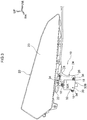
Fig. 3 is a perspective view showing a headlamp and a sensor configuring the mounting structure according to the present embodiment; -
Fig. 4 is a bottom plan view showing the headlamp and the sensor configuring the mounting structure according to the present embodiment; -
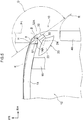
Fig. 5 is a plan view showing schematically the mounting structure according to the present embodiment; -
Fig. 6 is a side view showing schematically the mounting structure according to the present embodiment; and -
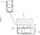
Fig. 7 is a plan view showing a state where the sensor of the vehicle including the mounting structure according to the present embodiment detects a crossing vehicle. - An embodiment according to the present disclosure will be described in detail below based on the drawings. Note that for convenience of explanation, an arrow UP, an arrow FR, and an arrow RH appropriately indicated in each of the drawings are assumed to be, respectively, a vehicle upward direction, a vehicle frontward direction, and a vehicle rightward direction. Moreover, in the description below, when directions of up/down, front/rear, and left/right are described, these are assumed to indicate up/down in a vehicle vertical direction, front/rear in a vehicle front-rear direction, and left/right in a vehicle left-right direction (vehicle width direction), unless otherwise specifically stated.
- As shown in
Figs. 1 and2 , amounting structure 10 of asensor 30 serving as a vehicle periphery monitoring device according to the present embodiment includes afront bumper reinforcement 14, made of a metal, which is extended in the vehicle width direction to be disposed in a frontward end section of avehicle 12. Thefront bumper reinforcement 14 is installed, via a crash box 16 (refer toFig. 5 ), in front end sections of a left/right pair of front side members (illustration of which is omitted), and is formed in a rectangular closed cross-sectional shape in a cross-sectional view orthogonal to the vehicle width direction. - Moreover, the
mounting structure 10 according to the present embodiment includes aheadlamp 20 disposed further in a vehicle body upward direction than thefront bumper reinforcement 14 and at an outward end section in the vehicle width direction of thevehicle 12. As shown inFigs. 3 and4 , theheadlamp 20 has alamp housing 22 formed in a casing shape by a resin material, and an unillustrated light source, reflector, lens, and so on, are housed in thelamp housing 22. - In addition, the
lamp housing 22 is hermetically sealed and has a waterproof property. Moreover, a front wall of thelamp housing 22 is configured as a transparentouter lens 23. A resin material resistant to damage such as cracking is adopted in theouter lens 23, and theouter lens 23 undergoes the likes of a surface treatment having an ultraviolet absorbing function (ultraviolet degradation resistance) or a surface treatment inhibiting scratching. - This
outer lens 23 is configured so as to be exposed from a space surrounded by an unillustrated front bumper cover, front fender panel, and closed-state engine hood, and so as to transmit light that has been generated from the light source to be reflected by the reflector and made into a light beam by the lens. This results in a configuration whereby a certain region on a vehicle body frontward of thevehicle 12 is illuminated. - Moreover, as shown in
Figs. 1 ,2 , and6 , themounting structure 10 according to the present embodiment includes a control device (ECU) 36, serving as a vehicle component, which is disposed further in a vehicle body downward direction than the headlamp 20 (sensor 30). Thecontrol device 36 is housed in acover body 38, made of a resin, configured in a substantially rectangular box shape, and is electrically connected to thesensor 30, and so on. In other words, there is a configuration whereby information detected by thesensor 30 is transmitted to thecontrol device 36. - Furthermore, as shown in
Figs. 1 to 6 , themounting structure 10 according to the present embodiment includes thesensor 30 having a radar function that detects an object more frontwards to an outer side in the vehicle width direction of thevehicle 12 than a turning region (shown by an imaginary line R inFig. 5 ) of afront wheel 40. As shown inFigs. 2 to 4 , thesensor 30 is housed in acover body 32, made of a resin, configured in a substantially rectangular box shape, and is provided vertically downwardly, via abracket 24 made of a resin, on a lower surface of alower wall 22A of thelamp housing 22. - Describing in detail, the
bracket 24 has a flat plate shaped supportingwall 26 whose front surface is directed frontwards to an outer side in the vehicle width direction, and a plurality of (for example, three) through holes (illustration of which is omitted) are formed in certain places in an outer peripheral section of the supportingwall 26. Moreover, a total of threeleg sections 34 protruding to a vehicle body upward and to an outward and an inward in the vehicle width direction are integrally formed in, respectively, an upper wall and both of left and right side walls of thecover body 32 housing thesensor 30, and through holes (illustration of which is omitted) are respectively formed in tips of each of theleg sections 34. - Therefore, the
cover body 32 housing thesensor 30 is attached to the supportingwall 26 of thebracket 24 by being overlaid on the front surface of the supportingwall 26 such that each of the through holes of each of theleg sections 34 are communicated with each of the through holes of the supportingwall 26, and by abolt 18 being inserted in each of the through holes from a vehicle body frontward to be screwed into a nut (illustration of which is omitted). - In addition, a
flat plate section 28 configured in substantially a right angled triangular shape in bottom plan view shown inFig. 4 is integrally formed continuously with the supportingwall 26, in an upper end section of thebracket 24. In other words, thisbracket 24 is formed in substantially an inverted "L" shape in side view, and through holes (illustration of which is omitted) are respectively formed in each of apex portions (that is, three places) of theflat plate section 28. Moreover, a plurality of (three) through holes (illustration of which is omitted) corresponding to each of the through holes of theflat plate section 28 are formed in substantially a central portion in the vehicle width direction in the lower surface of thelower wall 22A of thelamp housing 22. - Therefore, the
bracket 24 is attached to the lower surface of thelower wall 22A of thelamp housing 22 by being overlaid on substantially the central portion in the vehicle width direction in the lower surface of thelower wall 22A such that each of the through holes of theflat plate section 28 are communicated with each of the through holes of thelower wall 22A of thelamp housing 22, and by thebolt 18 being inserted in each of the through holes from a vehicle body downward side to be screwed into the nut (illustration of which is omitted). - This results in a configuration in which the sensor 30 (cover body 32) is provided vertically downwardly, via the
bracket 24, on the lower surface of thelower wall 22A of thelamp housing 22, and is separated by a gap S1 (refer toFigs. 2 and5 ) in the vehicle width direction from anoutward end surface 14A of thefront bumper reinforcement 14, and is separated by a gap S2 (refer toFigs. 2 and6 ) in a vehicle body vertical direction from an upward end surface (hereafter, called "upper surface") 38A of thecover body 38 of thecontrol device 36. - Note that a mounting position of the
sensor 30, that is, a way of determining the gaps S1, S2, and so on, will be described in detail later. Moreover, a lower end section of thebracket 24 to which the sensor 30 (cover body 32) is attached is configured as a free end, and is configured to be not connected (not joined) to another vehicle component (illustration of which is omitted), or the like. - In addition, as shown in
Fig. 5 , thissensor 30 is disposed obliquely to a vehicle body front-rear direction and the vehicle width direction (so as to be directed frontwards to an outer side in the vehicle width direction) in planar view, and its installation angle with respect to the vehicle body front-rear direction and the vehicle width direction in planar view is assumed to be an angle at which a detecting region (shown by an imaginary line D inFig. 5 ) in which the object is detected does not interfere with (does not overlap) a turning region (imaginary line R) of thefront wheel 40. - Moreover, this
sensor 30 has a detecting region by which it is possible that, as shown in, for example,Fig. 7 , in cases in which thevehicle 12 of oneself and a crossingvehicle 13 of another person mutually enter an intersection, specifically, in a case in which the crossingvehicle 13 approaches from a right side (or a left side) of thevehicle 12 driven by oneself, a front section of thecrossing vehicle 13 separated by at least a distance L of 30 m from a vehicle width directionouter end section 12A of a front section of thevehicle 12 in planar view, is detected. - Note that this "distance L of 30 m" refers to a distance calculated from the fact that in order for the
vehicle 12 to detect thecrossing vehicle 13 two seconds before collision when a speed of thevehicle 12 is, for example, 30 km per hour to 60 km per hour which is a speed limit of a city area, thecrossing vehicle 13 must be separated by 17 m to 33 m from thevehicle 12. - Now, the way of determining the mounting position (gaps S1, S2, and so on) of the
sensor 30 provided vertically downwardly via thebracket 24 on thelamp housing 22, will be further described. This mounting position of thesensor 30 is determined based on a regulatory test. The "regulatory test" in the present embodiment refers to a test described in GTR (Global Technical Regulation) NO. 9 PEDESTRIAN SAFETY (Established in the Global Registry on 12 November 2008). - First, a way of determining a position in the vehicle width direction (gap S1) and a position in the vehicle body front-rear direction with respect to the
front bumper reinforcement 14 of thesensor 30, will be described. What is shown by an imaginary line P1 inFig. 5 is a dummy member imitating a leg of a pedestrian. An entry position and an entry amount to a vehicle body rearward direction when the leg of the pedestrian has collided further outward in the vehicle width direction than an outward end section of thefront bumper reinforcement 14, of an entry region of the pedestrian with respect to thevehicle 12 shown by an imaginary line K inFig. 5 , are obtained based on conditions of the above-described regulatory test for each vehicle type. - In the present embodiment, the mounting position of the
sensor 30 is determined with reference to the entry position and the entry amount. Specifically, in order that, in planar view, a vehicle width direction inwardfront end section 32A of thecover body 32 of thesensor 30 will be further in the vehicle width outward direction to an extent of a certain gap α than the entry position with respect to the front section of thevehicle 12 of the leg of the pedestrian, that is, an actual strike-point position H, the inwardfront end section 32A of thesensor 30 is disposed in a position separated by the gap S1 (of not less than the gap α) from the vehicle width directionoutward end surface 14A of thefront bumper reinforcement 14, and is disposed in a position that is further in the vehicle body rearward direction to an extent of a certain gap β than the above-described entry amount. Note that the gaps α, β are assumed to be about 20 mm, for example. - Next, a way of determining a position in the vehicle body vertical direction (gap S2) of the
sensor 30 will be described. What is shown by an imaginary line P2 inFig. 6 is a dummy member imitating the pedestrian. In a case in which, as shown inFig. 6 , the pedestrian has collided with thevehicle 12 and the pedestrian has ridden up on an upper surface of the front section (engine hood or front fender panel) of thevehicle 12, the front section of thevehicle 12 is depressed in the vehicle body downward direction by a weight of the pedestrian, and a depression amount in the vehicle body downward direction is obtained based on conditions of the above-described regulatory test for each vehicle type. - In the present embodiment, the mounting position of the
sensor 30 is determined with reference to the depression amount. Specifically, thesensor 30 has alower surface 32B of itscover body 32 disposed further in the vehicle body upward direction than theupper surface 38A of thecover body 38 of thecontrol device 36 to an extent of the gap S2 which is slightly larger than the above-described depression amount with respect to the front section of thevehicle 12 of the pedestrian. In other words, the control device 36 (cover body 38) is attached to thevehicle 12 such that the gap S2 separates thelower surface 32B of thecover body 32 from theupper surface 38A of thecover body 38. - Next, operations of the mounting
structure 10 of thesensor 30 according to the present embodiment configured as above, will be described. - As described above, the
sensor 30 is provided vertically downwardly, via thebracket 24, on the lower surface of thelower wall 22A of thelamp housing 22 configuring theheadlamp 20. Moreover, thissensor 30 is disposed obliquely to the vehicle body front-rear direction and the vehicle width direction (so as to be directed frontwards to an outer side in the vehicle width direction) in planar view, and its installation angle is assumed to be an angle at which a detecting region (imaginary line D) in which the object is detected does not interfere with a turning region (imaginary line R) of thefront wheel 40. - Therefore, it is prevented that the
front wheel 40 adversely affects detection by thesensor 30. For example, it is prevented that thefront wheel 40 is misdetected as the object by thesensor 30. In addition, as shown inFig. 7 , in the case of detecting the crossingvehicle 13 at an intersection, particularly, even in the case of an intersection where there is a shielding object such as a wall W in a position separated by 1 m in the vehicle width direction from thevehicle 12 and visibility is poor, the crossingvehicle 13 can be detected by thesensor 30. Moreover, even during running of thevehicle 12, an alongside vehicle that is running along a side of thevehicle 12 can be detected by thissensor 30, hence lane-changing, and so on, can be assisted. - Incidentally, a frontward sensor (illustration of which is omitted) being mounted close to a center in the vehicle width direction of the front section of the
vehicle 12, to detect frontwards of thevehicle 12 driven by oneself, mainly a preceding vehicle, is known as prior art. However, if attempting to achieve more highly precise sensing in an automatic driving vehicle, mere detection of frontwards of thevehicle 12 could not be said to be sufficient. - In the present embodiment, the
sensor 30 is provided so as to have a detecting region that does not interfere with the turning region of thefront wheel 40, hence sides to both left and right from a central section in the vehicle width direction of thevehicle 12 and, furthermore, the crossingvehicle 13 or the alongside vehicle during lane-changing can be precisely detected. In other words, the present embodiment makes it possible to achieve more highly precise sensing in an automatic driving vehicle, and makes it possible to construct part of a preventive safety system capable of handling a variety of circumstances during running of thevehicle 12. - Moreover, as described above, the lower end section of the
bracket 24 to which the sensor 30 (cover body 32) is attached is configured as a free end, and thelower surface 32B of thecover body 32 of thesensor 30 is disposed so as to be separated by the gap S2 in the vehicle body vertical direction from theupper surface 38A of thecover body 38 of thecontrol device 36. - Therefore, even if the pedestrian collides with the front section of the
vehicle 12 and, as shown inFig. 6 , the pedestrian rides up on the front section of thevehicle 12 whereby aheadlamp 20 side moves (is depressed) in the vehicle body downward direction, the sensor 30 (cover body 32) can move in the vehicle body downward direction along with thebracket 24, hence a reaction force (load) is not exerted on the pedestrian by the sensor 30 (cover body 32). Hence, an injury value exerted on the pedestrian can be reduced. - In addition, as shown in
Fig. 5 , thesensor 30 has the vehicle width direction inwardfront end section 32A of itscover body 32 disposed so as to be separated by the gap S1 in the vehicle width direction from the vehicle width directionoutward end surface 14A of thefront bumper reinforcement 14. Moreover, in addition, this sensor 30 (cover body 32) is disposed further in the vehicle body rearward direction than the entry amount in the vehicle body rearward direction of the leg of the pedestrian obtained based on conditions of the above-described regulatory test. - Therefore, even if the leg of the pedestrian collides with the front section of the
vehicle 12 further in in the vehicle width outward direction than an outward end section in the vehicle width direction of thefront bumper reinforcement 14, it is suppressed or prevented that the leg of the pedestrian collides with the sensor 30 (cover body 32) via the front bumper cover. As a result, it can be suppressed or prevented that a reaction force (load) is exerted on the pedestrian by the sensor 30 (cover body 32), and the injury value exerted on the pedestrian can be reduced. - Moreover, the
bracket 24 to which the sensor 30 (cover body 32) is attached and thelamp housing 22 are made of a resin, hence, even supposing the leg of the pedestrian collides with the sensor 30 (cover body 32) via the front bumper cover, theflat plate section 28 of thebracket 24 can be broken off (separated by splitting) from thelamp housing 22 due to input of a collision load. Hence, even in this case, it can be suppressed or prevented that a reaction force (load) is exerted on the pedestrian by the sensor 30 (cover body 32), and the injury value exerted on the pedestrian can be reduced. - In addition, this sensor 30 (cover body 32) is provided vertically downwardly on the lower surface of the
lower wall 22A of thelamp housing 22 configuring theheadlamp 20, and is not provided at an inner surface of the front bumper cover or at a front bumper retainer (illustration of which is omitted), hence even when, for example, an obstacle has collided with the front bumper cover in a relatively minor way, there is no risk of a position or angle of thesensor 30 misaligning (it is difficult for misalignment of a position or angle of thesensor 30 to occur). - Moreover, as shown in
Fig. 1 , because the sensor can be seen if the front bumper cover is removed (because it is possible to remove only the front bumper cover from thevehicle 12 in a state where thesensor 30 is mounted in the vehicle 12), there is no need to change a structure of the front bumper cover in order to measure an installation state (position or angle) of thesensor 30. In other words, the present embodiment makes it possible for the position or angle of thesensor 30 to be measured without affecting design of thevehicle 12. - The mounting
structure 10 of the vehicle periphery monitoring device (sensor 30) according to the present embodiment has been described above based on the drawings. However, the mountingstructure 10 of the vehicle periphery mounting device according to the present embodiment is not limited to what is illustrated in the drawings, and may have its design appropriately changed in a range not departing from the spirit of the present disclosure. - For example, the
bracket 24 to which the sensor 30 (cover body 32) is attached is not limited to being made of a resin, and may be made of a metal such as sheet metal. Moreover, the vehicle component disposed more to the vehicle body downward side than the headlamp 20 (sensor 30) is not limited to thecontrol device 36. - In addition, the
sensor 30 may adopt a configuration in which the upper end section of thecover body 32 housing thesensor 30 is attached directly to the lower surface of thelower wall 22A of thelamp housing 22 configuring theheadlamp 20, without mediation of thebracket 24. Moreover, a joining means of the sensor 30 (cover body 32) to the supportingwall 26 of thebracket 24 or a joining means of the bracket 24 (flat plate section 28) to thelower wall 22A of thelamp housing 22 are not limited to fastening by a bolt and a nut.
Claims (3)
- A mounting structure (10) of a vehicle periphery monitoring device (30), comprising:a front bumper reinforcement (14) that extends along a vehicle width direction and is disposed in a frontward end section at a vehicle body (12) of a vehicle;a headlamp (20) having a lamp housing (22), a light source being housed in the lamp housing, the headlamp being disposed further in a vehicle body upward direction than the front bumper reinforcement and at an outward end section in the vehicle width direction of the vehicle;a vehicle component (36) disposed further in a vehicle body downward direction than the headlamp; anda vehicle periphery monitoring device disposed further in a vehicle body downward direction than a lower surface of the lamp housing, the vehicle periphery monitoring device being separated by a first gap (S1) in the vehicle width direction from an outward end surface (14A) in the vehicle width direction of the front bumper reinforcement, and being separated by a second gap (S2) in a vehicle body vertical direction from an upward end surface (38A) of the vehicle component, the vehicle periphery monitoring device detecting an object frontwards and outwards in the vehicle width direction of the vehicle.
- The mounting structure (10) of the vehicle periphery monitoring device (30) according to claim 1, wherein an installation angle in planar view of the vehicle periphery monitoring device is assumed to be an angle at which a detecting region in which the object is detected does not interfere with a turning region of a front wheel (40).
- The mounting structure (10) of the vehicle periphery monitoring device (30) according to claim 1 or 2, wherein the vehicle periphery monitoring device is attached to a bracket (24), the bracket suspends downwardly in the vehicle vertical direction from the lower surface of the lamp housing (22).
Applications Claiming Priority (1)
| Application Number | Priority Date | Filing Date | Title |
|---|---|---|---|
| JP2016240447A JP6802053B2 (en) | 2016-12-12 | 2016-12-12 | Vehicle peripheral monitoring device mounting structure |
Publications (2)
| Publication Number | Publication Date |
|---|---|
| EP3333023A1 true EP3333023A1 (en) | 2018-06-13 |
| EP3333023B1 EP3333023B1 (en) | 2020-09-02 |
Family
ID=60654790
Family Applications (1)
| Application Number | Title | Priority Date | Filing Date |
|---|---|---|---|
| EP17206198.8A Active EP3333023B1 (en) | 2016-12-12 | 2017-12-08 | Mounting structure of vehicle periphery monitoring device |
Country Status (7)
| Country | Link |
|---|---|
| US (1) | US10399522B2 (en) |
| EP (1) | EP3333023B1 (en) |
| JP (1) | JP6802053B2 (en) |
| KR (1) | KR102092792B1 (en) |
| CN (1) | CN108216094B (en) |
| BR (1) | BR102017026358A2 (en) |
| RU (1) | RU2673420C1 (en) |
Cited By (1)
| Publication number | Priority date | Publication date | Assignee | Title |
|---|---|---|---|---|
| DE102019113492B4 (en) | 2019-05-21 | 2021-11-11 | Dr. Ing. H.C. F. Porsche Aktiengesellschaft | Laser scanner arrangement |
Families Citing this family (11)
| Publication number | Priority date | Publication date | Assignee | Title |
|---|---|---|---|---|
| JP6802053B2 (en) * | 2016-12-12 | 2020-12-16 | トヨタ自動車株式会社 | Vehicle peripheral monitoring device mounting structure |
| JP6642477B2 (en) * | 2017-02-21 | 2020-02-05 | トヨタ自動車株式会社 | Vehicle front structure |
| JP7124577B2 (en) * | 2018-09-06 | 2022-08-24 | トヨタ自動車株式会社 | Radar installation structure |
| JP7267807B2 (en) * | 2019-03-28 | 2023-05-02 | 日野自動車株式会社 | Perimeter monitoring system |
| JP7131508B2 (en) | 2019-08-21 | 2022-09-06 | トヨタ自動車株式会社 | radar equipment |
| JP2022158504A (en) * | 2021-04-02 | 2022-10-17 | トヨタ自動車株式会社 | vehicle structure |
| JP7448099B2 (en) * | 2021-08-24 | 2024-03-12 | 三菱自動車工業株式会社 | Vehicle lighting installation structure |
| JP7470724B2 (en) * | 2022-02-21 | 2024-04-18 | 本田技研工業株式会社 | Mounting structure for object detection device on vehicle body |
| JP2024006105A (en) * | 2022-06-30 | 2024-01-17 | 株式会社ニフコ | Mounting structure for bumper retainers and vehicle parts |
| JP7733698B2 (en) * | 2023-07-28 | 2025-09-03 | 本田技研工業株式会社 | Vehicle front structure |
| KR20250046473A (en) * | 2023-09-27 | 2025-04-03 | 현대자동차주식회사 | Radar unit Mounting Structure of Bumper |
Citations (6)
| Publication number | Priority date | Publication date | Assignee | Title |
|---|---|---|---|---|
| DE19731754A1 (en) * | 1997-07-23 | 1999-02-04 | Spies Martin Dipl Ing Fh | Combination distance sensors with headlamps |
| JP2007106199A (en) | 2005-10-12 | 2007-04-26 | Mitsuba Corp | Vehicle periphery monitor device |
| JP2010066092A (en) * | 2008-09-10 | 2010-03-25 | Nissan Diesel Motor Co Ltd | Device for adjustment of antenna axis of on-vehicle radar |
| DE102009045860A1 (en) * | 2008-10-21 | 2010-04-22 | Toyota Jidosha Kabushiki Kaisha, Toyota-shi | radar |
| JP2010204030A (en) * | 2009-03-05 | 2010-09-16 | Fuji Heavy Ind Ltd | Antenna for in-vehicle radar |
| EP2233367A1 (en) * | 2009-03-26 | 2010-09-29 | Faurecia Bloc Avant | Fornt face modul for motorvehicle comprising a structural frame and a bumper |
Family Cites Families (25)
| Publication number | Priority date | Publication date | Assignee | Title |
|---|---|---|---|---|
| JP4299036B2 (en) * | 2003-03-31 | 2009-07-22 | シャープ株式会社 | Vehicle monitoring device |
| JP2007106198A (en) | 2005-10-12 | 2007-04-26 | Mitsuba Corp | Vehicle periphery monitor device |
| CN101085625B (en) * | 2006-06-08 | 2011-05-11 | 马自达汽车株式会社 | Vehicle front structure |
| KR101318637B1 (en) * | 2006-07-20 | 2013-10-16 | 한라비스테온공조 주식회사 | Front End Module for Automobile |
| JP2008146933A (en) * | 2006-12-07 | 2008-06-26 | Koito Mfg Co Ltd | Vehicle lighting |
| JP4842161B2 (en) * | 2007-01-31 | 2011-12-21 | 株式会社小糸製作所 | Vehicle lighting |
| US20080315050A1 (en) | 2007-06-21 | 2008-12-25 | Buckley Stephen J | Vehicle blind spot radar sensor mount |
| JP4905372B2 (en) * | 2007-06-27 | 2012-03-28 | 日産自動車株式会社 | Mounting structure of impact sensor for vehicle |
| JP5285405B2 (en) | 2008-12-02 | 2013-09-11 | 株式会社小糸製作所 | Vehicle lighting |
| JP5130192B2 (en) * | 2008-12-12 | 2013-01-30 | 株式会社小糸製作所 | Vehicle lighting |
| JP5370822B2 (en) * | 2009-03-30 | 2013-12-18 | スズキ株式会社 | Vehicle front structure |
| JP4919179B2 (en) | 2010-05-11 | 2012-04-18 | 独立行政法人電子航法研究所 | Millimeter wave radar built-in headlamp |
| MX2013009589A (en) * | 2011-03-07 | 2014-03-12 | Faurecia Exteriors Gmbh | Multifunctional support for a motor vehicle. |
| JP5862065B2 (en) * | 2011-06-15 | 2016-02-16 | マツダ株式会社 | Front body structure of the vehicle |
| DE102012017669A1 (en) * | 2012-09-07 | 2014-03-13 | Valeo Schalter Und Sensoren Gmbh | Arrangement with a trim part and a radar sensor, motor vehicle and method for producing an arrangement |
| KR101459910B1 (en) * | 2013-05-28 | 2014-11-07 | 현대자동차주식회사 | Radar apparatus for vehicle |
| JP6183136B2 (en) * | 2013-10-15 | 2017-08-23 | スズキ株式会社 | Body front structure |
| JP6515497B2 (en) * | 2014-11-17 | 2019-05-22 | スズキ株式会社 | Front body structure |
| JP6447305B2 (en) * | 2015-03-30 | 2019-01-09 | トヨタ自動車株式会社 | Vehicle peripheral information detection structure |
| DE102015109702A1 (en) * | 2015-06-17 | 2016-12-22 | Hbpo Gmbh | Closing device for closing a functionally essential component of a vehicle |
| JP6555072B2 (en) * | 2015-10-16 | 2019-08-07 | 株式会社デンソー | Protection control device |
| US9828036B2 (en) * | 2015-11-24 | 2017-11-28 | Srg Global Inc. | Active grille shutter system with integrated radar |
| US9925912B2 (en) * | 2015-12-07 | 2018-03-27 | GM Global Technology Operations LLC | Exterior lighting and object detection assembly |
| JP6802053B2 (en) * | 2016-12-12 | 2020-12-16 | トヨタ自動車株式会社 | Vehicle peripheral monitoring device mounting structure |
| US9956993B1 (en) * | 2017-01-20 | 2018-05-01 | Ford Global Technologies, Llc | Vehicle front impact sensor with impact resistant carriage |
-
2016
- 2016-12-12 JP JP2016240447A patent/JP6802053B2/en active Active
-
2017
- 2017-12-06 CN CN201711276195.2A patent/CN108216094B/en active Active
- 2017-12-06 RU RU2017142581A patent/RU2673420C1/en active
- 2017-12-06 US US15/832,842 patent/US10399522B2/en active Active
- 2017-12-06 KR KR1020170166372A patent/KR102092792B1/en active Active
- 2017-12-07 BR BR102017026358A patent/BR102017026358A2/en active Search and Examination
- 2017-12-08 EP EP17206198.8A patent/EP3333023B1/en active Active
Patent Citations (6)
| Publication number | Priority date | Publication date | Assignee | Title |
|---|---|---|---|---|
| DE19731754A1 (en) * | 1997-07-23 | 1999-02-04 | Spies Martin Dipl Ing Fh | Combination distance sensors with headlamps |
| JP2007106199A (en) | 2005-10-12 | 2007-04-26 | Mitsuba Corp | Vehicle periphery monitor device |
| JP2010066092A (en) * | 2008-09-10 | 2010-03-25 | Nissan Diesel Motor Co Ltd | Device for adjustment of antenna axis of on-vehicle radar |
| DE102009045860A1 (en) * | 2008-10-21 | 2010-04-22 | Toyota Jidosha Kabushiki Kaisha, Toyota-shi | radar |
| JP2010204030A (en) * | 2009-03-05 | 2010-09-16 | Fuji Heavy Ind Ltd | Antenna for in-vehicle radar |
| EP2233367A1 (en) * | 2009-03-26 | 2010-09-29 | Faurecia Bloc Avant | Fornt face modul for motorvehicle comprising a structural frame and a bumper |
Cited By (1)
| Publication number | Priority date | Publication date | Assignee | Title |
|---|---|---|---|---|
| DE102019113492B4 (en) | 2019-05-21 | 2021-11-11 | Dr. Ing. H.C. F. Porsche Aktiengesellschaft | Laser scanner arrangement |
Also Published As
| Publication number | Publication date |
|---|---|
| CN108216094B (en) | 2020-12-01 |
| KR102092792B1 (en) | 2020-03-24 |
| US10399522B2 (en) | 2019-09-03 |
| EP3333023B1 (en) | 2020-09-02 |
| KR20180067418A (en) | 2018-06-20 |
| JP2018095039A (en) | 2018-06-21 |
| RU2673420C1 (en) | 2018-11-26 |
| CN108216094A (en) | 2018-06-29 |
| BR102017026358A2 (en) | 2018-10-30 |
| JP6802053B2 (en) | 2020-12-16 |
| US20180162306A1 (en) | 2018-06-14 |
Similar Documents
| Publication | Publication Date | Title |
|---|---|---|
| EP3333023B1 (en) | Mounting structure of vehicle periphery monitoring device | |
| CN112793517B (en) | Sensor installation structure | |
| US11305712B2 (en) | Sensor mounting structure for vehicle | |
| CN103241240B (en) | For the device for protecting outside rear-view mirror to be collided with flanking obstacle in the car | |
| CN102026848B (en) | Vehicle side door structure | |
| US9320156B2 (en) | Mounting structure for casing of occupant protection device control unit | |
| US10024970B2 (en) | Sensor housing assembly for attachment to a motor vehicle | |
| CN112867638B (en) | Bumper reinforcement with sensor support plate for integration in vehicle front assembly | |
| KR102106345B1 (en) | Rear-side alert system and controlling method thereof | |
| KR20210085734A (en) | Mounting apparatus of sensor for autonomous driving vehicle | |
| RU150713U1 (en) | VEHICLE FACING ELEMENT WITH SHOCK SENSOR UNIT | |
| JP5862065B2 (en) | Front body structure of the vehicle | |
| JP6048447B2 (en) | Car electrical equipment mounting structure | |
| JP4635467B2 (en) | Vehicle collision detection sensor arrangement structure | |
| JP6304281B2 (en) | Bumper structure of vehicle | |
| JP2014133448A (en) | Vehicle collision detection device | |
| JP4836977B2 (en) | Sensor layout | |
| CN201423994Y (en) | Cars with Pedestrian Protection Systems | |
| JP7267807B2 (en) | Perimeter monitoring system | |
| JP5700865B2 (en) | Vehicle headlight unit | |
| CN223791443U (en) | A radar-embedded installation structure for mining trucks and mining trucks | |
| JP7733698B2 (en) | Vehicle front structure | |
| JP2007230285A (en) | Obstacle detection device | |
| KR20250090629A (en) | Vehicle side mirror protection apparatus | |
| KR19980048376U (en) | Side sensing structure of side mirror |
Legal Events
| Date | Code | Title | Description |
|---|---|---|---|
| PUAI | Public reference made under article 153(3) epc to a published international application that has entered the european phase |
Free format text: ORIGINAL CODE: 0009012 |
|
| STAA | Information on the status of an ep patent application or granted ep patent |
Free format text: STATUS: REQUEST FOR EXAMINATION WAS MADE |
|
| 17P | Request for examination filed |
Effective date: 20171208 |
|
| AK | Designated contracting states |
Kind code of ref document: A1 Designated state(s): AL AT BE BG CH CY CZ DE DK EE ES FI FR GB GR HR HU IE IS IT LI LT LU LV MC MK MT NL NO PL PT RO RS SE SI SK SM TR |
|
| AX | Request for extension of the european patent |
Extension state: BA ME |
|
| STAA | Information on the status of an ep patent application or granted ep patent |
Free format text: STATUS: EXAMINATION IS IN PROGRESS |
|
| 17Q | First examination report despatched |
Effective date: 20190404 |
|
| GRAP | Despatch of communication of intention to grant a patent |
Free format text: ORIGINAL CODE: EPIDOSNIGR1 |
|
| STAA | Information on the status of an ep patent application or granted ep patent |
Free format text: STATUS: GRANT OF PATENT IS INTENDED |
|
| INTG | Intention to grant announced |
Effective date: 20200402 |
|
| GRAS | Grant fee paid |
Free format text: ORIGINAL CODE: EPIDOSNIGR3 |
|
| GRAA | (expected) grant |
Free format text: ORIGINAL CODE: 0009210 |
|
| STAA | Information on the status of an ep patent application or granted ep patent |
Free format text: STATUS: THE PATENT HAS BEEN GRANTED |
|
| AK | Designated contracting states |
Kind code of ref document: B1 Designated state(s): AL AT BE BG CH CY CZ DE DK EE ES FI FR GB GR HR HU IE IS IT LI LT LU LV MC MK MT NL NO PL PT RO RS SE SI SK SM TR |
|
| REG | Reference to a national code |
Ref country code: GB Ref legal event code: FG4D |
|
| REG | Reference to a national code |
Ref country code: AT Ref legal event code: REF Ref document number: 1308475 Country of ref document: AT Kind code of ref document: T Effective date: 20200915 Ref country code: CH Ref legal event code: EP |
|
| REG | Reference to a national code |
Ref country code: DE Ref legal event code: R096 Ref document number: 602017022715 Country of ref document: DE |
|
| REG | Reference to a national code |
Ref country code: IE Ref legal event code: FG4D |
|
| REG | Reference to a national code |
Ref country code: LT Ref legal event code: MG4D |
|
| PG25 | Lapsed in a contracting state [announced via postgrant information from national office to epo] |
Ref country code: NO Free format text: LAPSE BECAUSE OF FAILURE TO SUBMIT A TRANSLATION OF THE DESCRIPTION OR TO PAY THE FEE WITHIN THE PRESCRIBED TIME-LIMIT Effective date: 20201202 Ref country code: FI Free format text: LAPSE BECAUSE OF FAILURE TO SUBMIT A TRANSLATION OF THE DESCRIPTION OR TO PAY THE FEE WITHIN THE PRESCRIBED TIME-LIMIT Effective date: 20200902 Ref country code: LT Free format text: LAPSE BECAUSE OF FAILURE TO SUBMIT A TRANSLATION OF THE DESCRIPTION OR TO PAY THE FEE WITHIN THE PRESCRIBED TIME-LIMIT Effective date: 20200902 Ref country code: HR Free format text: LAPSE BECAUSE OF FAILURE TO SUBMIT A TRANSLATION OF THE DESCRIPTION OR TO PAY THE FEE WITHIN THE PRESCRIBED TIME-LIMIT Effective date: 20200902 Ref country code: SE Free format text: LAPSE BECAUSE OF FAILURE TO SUBMIT A TRANSLATION OF THE DESCRIPTION OR TO PAY THE FEE WITHIN THE PRESCRIBED TIME-LIMIT Effective date: 20200902 Ref country code: BG Free format text: LAPSE BECAUSE OF FAILURE TO SUBMIT A TRANSLATION OF THE DESCRIPTION OR TO PAY THE FEE WITHIN THE PRESCRIBED TIME-LIMIT Effective date: 20201202 Ref country code: GR Free format text: LAPSE BECAUSE OF FAILURE TO SUBMIT A TRANSLATION OF THE DESCRIPTION OR TO PAY THE FEE WITHIN THE PRESCRIBED TIME-LIMIT Effective date: 20201203 |
|
| REG | Reference to a national code |
Ref country code: NL Ref legal event code: MP Effective date: 20200902 |
|
| REG | Reference to a national code |
Ref country code: AT Ref legal event code: MK05 Ref document number: 1308475 Country of ref document: AT Kind code of ref document: T Effective date: 20200902 |
|
| PG25 | Lapsed in a contracting state [announced via postgrant information from national office to epo] |
Ref country code: LV Free format text: LAPSE BECAUSE OF FAILURE TO SUBMIT A TRANSLATION OF THE DESCRIPTION OR TO PAY THE FEE WITHIN THE PRESCRIBED TIME-LIMIT Effective date: 20200902 Ref country code: RS Free format text: LAPSE BECAUSE OF FAILURE TO SUBMIT A TRANSLATION OF THE DESCRIPTION OR TO PAY THE FEE WITHIN THE PRESCRIBED TIME-LIMIT Effective date: 20200902 Ref country code: PL Free format text: LAPSE BECAUSE OF FAILURE TO SUBMIT A TRANSLATION OF THE DESCRIPTION OR TO PAY THE FEE WITHIN THE PRESCRIBED TIME-LIMIT Effective date: 20200902 |
|
| PG25 | Lapsed in a contracting state [announced via postgrant information from national office to epo] |
Ref country code: CZ Free format text: LAPSE BECAUSE OF FAILURE TO SUBMIT A TRANSLATION OF THE DESCRIPTION OR TO PAY THE FEE WITHIN THE PRESCRIBED TIME-LIMIT Effective date: 20200902 Ref country code: PT Free format text: LAPSE BECAUSE OF FAILURE TO SUBMIT A TRANSLATION OF THE DESCRIPTION OR TO PAY THE FEE WITHIN THE PRESCRIBED TIME-LIMIT Effective date: 20210104 Ref country code: RO Free format text: LAPSE BECAUSE OF FAILURE TO SUBMIT A TRANSLATION OF THE DESCRIPTION OR TO PAY THE FEE WITHIN THE PRESCRIBED TIME-LIMIT Effective date: 20200902 Ref country code: SM Free format text: LAPSE BECAUSE OF FAILURE TO SUBMIT A TRANSLATION OF THE DESCRIPTION OR TO PAY THE FEE WITHIN THE PRESCRIBED TIME-LIMIT Effective date: 20200902 Ref country code: EE Free format text: LAPSE BECAUSE OF FAILURE TO SUBMIT A TRANSLATION OF THE DESCRIPTION OR TO PAY THE FEE WITHIN THE PRESCRIBED TIME-LIMIT Effective date: 20200902 |
|
| PG25 | Lapsed in a contracting state [announced via postgrant information from national office to epo] |
Ref country code: IS Free format text: LAPSE BECAUSE OF FAILURE TO SUBMIT A TRANSLATION OF THE DESCRIPTION OR TO PAY THE FEE WITHIN THE PRESCRIBED TIME-LIMIT Effective date: 20210102 Ref country code: ES Free format text: LAPSE BECAUSE OF FAILURE TO SUBMIT A TRANSLATION OF THE DESCRIPTION OR TO PAY THE FEE WITHIN THE PRESCRIBED TIME-LIMIT Effective date: 20200902 Ref country code: AT Free format text: LAPSE BECAUSE OF FAILURE TO SUBMIT A TRANSLATION OF THE DESCRIPTION OR TO PAY THE FEE WITHIN THE PRESCRIBED TIME-LIMIT Effective date: 20200902 Ref country code: AL Free format text: LAPSE BECAUSE OF FAILURE TO SUBMIT A TRANSLATION OF THE DESCRIPTION OR TO PAY THE FEE WITHIN THE PRESCRIBED TIME-LIMIT Effective date: 20200902 |
|
| REG | Reference to a national code |
Ref country code: DE Ref legal event code: R097 Ref document number: 602017022715 Country of ref document: DE |
|
| PG25 | Lapsed in a contracting state [announced via postgrant information from national office to epo] |
Ref country code: SK Free format text: LAPSE BECAUSE OF FAILURE TO SUBMIT A TRANSLATION OF THE DESCRIPTION OR TO PAY THE FEE WITHIN THE PRESCRIBED TIME-LIMIT Effective date: 20200902 |
|
| PLBE | No opposition filed within time limit |
Free format text: ORIGINAL CODE: 0009261 |
|
| STAA | Information on the status of an ep patent application or granted ep patent |
Free format text: STATUS: NO OPPOSITION FILED WITHIN TIME LIMIT |
|
| REG | Reference to a national code |
Ref country code: CH Ref legal event code: PL |
|
| 26N | No opposition filed |
Effective date: 20210603 |
|
| PG25 | Lapsed in a contracting state [announced via postgrant information from national office to epo] |
Ref country code: MC Free format text: LAPSE BECAUSE OF FAILURE TO SUBMIT A TRANSLATION OF THE DESCRIPTION OR TO PAY THE FEE WITHIN THE PRESCRIBED TIME-LIMIT Effective date: 20200902 Ref country code: SI Free format text: LAPSE BECAUSE OF FAILURE TO SUBMIT A TRANSLATION OF THE DESCRIPTION OR TO PAY THE FEE WITHIN THE PRESCRIBED TIME-LIMIT Effective date: 20200902 Ref country code: DK Free format text: LAPSE BECAUSE OF FAILURE TO SUBMIT A TRANSLATION OF THE DESCRIPTION OR TO PAY THE FEE WITHIN THE PRESCRIBED TIME-LIMIT Effective date: 20200902 |
|
| REG | Reference to a national code |
Ref country code: BE Ref legal event code: MM Effective date: 20201231 |
|
| PG25 | Lapsed in a contracting state [announced via postgrant information from national office to epo] |
Ref country code: IE Free format text: LAPSE BECAUSE OF NON-PAYMENT OF DUE FEES Effective date: 20201208 Ref country code: LU Free format text: LAPSE BECAUSE OF NON-PAYMENT OF DUE FEES Effective date: 20201208 Ref country code: IT Free format text: LAPSE BECAUSE OF FAILURE TO SUBMIT A TRANSLATION OF THE DESCRIPTION OR TO PAY THE FEE WITHIN THE PRESCRIBED TIME-LIMIT Effective date: 20200902 |
|
| PG25 | Lapsed in a contracting state [announced via postgrant information from national office to epo] |
Ref country code: CH Free format text: LAPSE BECAUSE OF NON-PAYMENT OF DUE FEES Effective date: 20201231 Ref country code: LI Free format text: LAPSE BECAUSE OF NON-PAYMENT OF DUE FEES Effective date: 20201231 |
|
| PG25 | Lapsed in a contracting state [announced via postgrant information from national office to epo] |
Ref country code: TR Free format text: LAPSE BECAUSE OF FAILURE TO SUBMIT A TRANSLATION OF THE DESCRIPTION OR TO PAY THE FEE WITHIN THE PRESCRIBED TIME-LIMIT Effective date: 20200902 Ref country code: MT Free format text: LAPSE BECAUSE OF FAILURE TO SUBMIT A TRANSLATION OF THE DESCRIPTION OR TO PAY THE FEE WITHIN THE PRESCRIBED TIME-LIMIT Effective date: 20200902 Ref country code: CY Free format text: LAPSE BECAUSE OF FAILURE TO SUBMIT A TRANSLATION OF THE DESCRIPTION OR TO PAY THE FEE WITHIN THE PRESCRIBED TIME-LIMIT Effective date: 20200902 |
|
| PG25 | Lapsed in a contracting state [announced via postgrant information from national office to epo] |
Ref country code: MK Free format text: LAPSE BECAUSE OF FAILURE TO SUBMIT A TRANSLATION OF THE DESCRIPTION OR TO PAY THE FEE WITHIN THE PRESCRIBED TIME-LIMIT Effective date: 20200902 |
|
| PG25 | Lapsed in a contracting state [announced via postgrant information from national office to epo] |
Ref country code: BE Free format text: LAPSE BECAUSE OF NON-PAYMENT OF DUE FEES Effective date: 20201231 |
|
| P01 | Opt-out of the competence of the unified patent court (upc) registered |
Effective date: 20230427 |
|
| PG25 | Lapsed in a contracting state [announced via postgrant information from national office to epo] |
Ref country code: NL Free format text: LAPSE BECAUSE OF NON-PAYMENT OF DUE FEES Effective date: 20200923 |
|
| REG | Reference to a national code |
Ref country code: DE Ref legal event code: R084 Ref document number: 602017022715 Country of ref document: DE |
|
| PGFP | Annual fee paid to national office [announced via postgrant information from national office to epo] |
Ref country code: DE Payment date: 20251028 Year of fee payment: 9 |
|
| PGFP | Annual fee paid to national office [announced via postgrant information from national office to epo] |
Ref country code: GB Payment date: 20251030 Year of fee payment: 9 |
|
| PGFP | Annual fee paid to national office [announced via postgrant information from national office to epo] |
Ref country code: FR Payment date: 20251117 Year of fee payment: 9 |
|
| REG | Reference to a national code |
Ref country code: GB Ref legal event code: 746 Effective date: 20260112 |