EP3333014B1 - Stoppvorrichtung für fahrzeugtransporter - Google Patents
Stoppvorrichtung für fahrzeugtransporter Download PDFInfo
- Publication number
- EP3333014B1 EP3333014B1 EP17205527.9A EP17205527A EP3333014B1 EP 3333014 B1 EP3333014 B1 EP 3333014B1 EP 17205527 A EP17205527 A EP 17205527A EP 3333014 B1 EP3333014 B1 EP 3333014B1
- Authority
- EP
- European Patent Office
- Prior art keywords
- stop device
- retainer bar
- base plate
- vehicle
- notch
- Prior art date
- Legal status (The legal status is an assumption and is not a legal conclusion. Google has not performed a legal analysis and makes no representation as to the accuracy of the status listed.)
- Not-in-force
Links
- 238000004873 anchoring Methods 0.000 claims description 7
- 230000000712 assembly Effects 0.000 claims description 7
- 238000000429 assembly Methods 0.000 claims description 7
- 230000000284 resting effect Effects 0.000 claims description 3
- 230000000295 complement effect Effects 0.000 claims description 2
- 230000037431 insertion Effects 0.000 description 5
- 238000003780 insertion Methods 0.000 description 5
- 230000000694 effects Effects 0.000 description 2
- 238000003466 welding Methods 0.000 description 2
- 230000006835 compression Effects 0.000 description 1
- 238000007906 compression Methods 0.000 description 1
- 238000010276 construction Methods 0.000 description 1
- 230000003014 reinforcing effect Effects 0.000 description 1
Images

Classifications
-
- B—PERFORMING OPERATIONS; TRANSPORTING
- B60—VEHICLES IN GENERAL
- B60P—VEHICLES ADAPTED FOR LOAD TRANSPORTATION OR TO TRANSPORT, TO CARRY, OR TO COMPRISE SPECIAL LOADS OR OBJECTS
- B60P3/00—Vehicles adapted to transport, to carry or to comprise special loads or objects
- B60P3/06—Vehicles adapted to transport, to carry or to comprise special loads or objects for carrying vehicles
- B60P3/07—Vehicles adapted to transport, to carry or to comprise special loads or objects for carrying vehicles for carrying road vehicles
- B60P3/073—Vehicle retainers
- B60P3/075—Vehicle retainers for wheels, hubs, or axle shafts
- B60P3/077—Wheel cradles, chocks, or wells
Definitions
- the present invention generally regards vehicle transporters and more in particular it regards stop devices used on vehicle transporters for locking the wheels of the vehicles transported thereon, such as disclosed in FR 2684054 A3 .
- Vehicle transporters conventionally have a loading deck provided with anchoring holes for positioning and locking the stop devices, which comprise a support base on the loading deck and a retainer bar located above the base and suitable to cooperate in a stop relationship with a wheel of a vehicle.
- the support base carries a first and a second engagement assembly each comprising a hook for insertion into an anchoring hole of the loading deck of the vehicle transporter, a helical spring, a cam member cooperating from beneath the retainer bar under the action of the spring, and a manual control rod for rotating the cam member in two different positions in which the hook is facing on opposite sides with respect to the retainer bar.
- the support base of the stop device usually extends - in a parallel continuous fashion - beneath the retainer bar and it has two end holes for mounting the two engagement assemblies.
- the assembly of the stop device is relatively complex in that it requires, for each engagement assembly, the positioning of the spring and the cam member between the base and the retainer bar, thus the insertion of the hook from beneath the base through the corresponding hole, and thus the joining between the cam member and the hook through a transversal pin inserted through respective corresponding holes.
- the object of the invention is to solve the aforementioned problem in a simple and efficient manner, and this object is attained thanks to the fact that the support base consists in a pair of plates separated from each other, located beneath the ends of the retainer bar and each formed with a lateral notch facing towards the interior of the stop device, and in that each engagement assembly is pre-assembled and mounted between the respective base plate and the retainer bar by means of lateral insertion into the relative notch.
- the stop device is manufactured in a considerably simplified and more economic manner.
- a circular locking ring which is inserted into a complementary recess of an auxiliary plate rigidly fixed on the respective support plate is conveniently interposed between the spring of each pre-assembled engagement assembly and the respective base plate.
- This recess is arranged above the notch of the support plate and it has an angular width greater than 180°.
- the stop device according to the invention designated to be applied in a known fashion to the loading deck of a vehicle transporter provided with anchoring holes, essentially consists in a stop element 1 formed by a robust horizontal bar with ends 2 folded vertically downwards, and a base for resting on the loading deck of the vehicle transporter.
- the base consists in a pair of mutually separated horizontal plates 3, 3 which are welded to the ends 2 of the retainer bar 1.
- Each engagement assembly 4 comprises, also in a generally known manner, a hook 5 formed by a horizontal tooth 6 configured to engage an anchoring hole of the loading deck of the vehicle transporter, and a vertical stem 7 whose top part is fixed in a bushing 8 obtained at the top part in a manner similar to a cam 9.
- the stem 7 of the hook 5 traverses the base plate 3, as outlined hereinafter, and a compression helical spring 10 which is interposed between the base plate 3 and the bushing 8 and it presses the cam 9 from beneath against the retainer bar 1.
- a manual control rod 11 traverses the bushing 8 and the stem 7 of the hook 5 and it can be actuated to rotate the engagement assembly 4 in one or the other of the two opposite positions in which - due to the cooperation between the cam member 9 and the stop element 1 - the horizontal part 6 of the hook 5 is rotated by 180°.
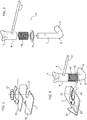
- each engagement assembly 4 is pre-assembled and subsequently mounted in the respective base plate 3 in a relatively simple and easy manner.
- each base plate 3 is formed with a lateral notch 12, facing towards the interior of the stop device.
- An auxiliary plate 13 formed with a recess 14 arranged above the notch 12 and having an angular width greater than 180°, is fixed on the base plate 3 by means of welding.
- the recess 14 is designated to receive a circular ring 15 resting on the base plate 3, which is thus locked against the effects of lateral movement with respect to the base plate 3 and thus the related notch 12.
- Figure 3 represents the various components of an engagement assembly 4 prior to being pre-assembled, and figure 4 shows the engagement assembly 4 in the pre-assembled condition in which the stem 7, subsequently to insertion thereof through the ring 15 and the helical spring 10, is fixed into the bushing 8 by welding.
- the engagement assembly 4 thus pre-assembled, is thus mounted on the relative base plate 3 by introducing the stem 7 of the hook 6 into the notch 12 sideways and thus positioning the ring 15 into the recess 14 of the auxiliary plate 13 from above. To carry out such insertion, the spring 10 must be compressed to an extent such to enable the cam 9 to be engaged beneath the retainer bar 1.
- Stiffening elements 16 projecting from each base plate 3 and welded to the ends 2 of the retainer bar 1 are conveniently provided for reinforcing such base plates 3 against the effects of torsional stress.
- stop device according to the invention can be manufactured in a considerably simpler and economic manner with respect to conventional stop devices whose engagement assemblies are assembled subsequently to mounting the relative components on a continuous support base.
Landscapes
- Engineering & Computer Science (AREA)
- Health & Medical Sciences (AREA)
- Public Health (AREA)
- Transportation (AREA)
- Mechanical Engineering (AREA)
- Auxiliary Methods And Devices For Loading And Unloading (AREA)
- Treatments For Attaching Organic Compounds To Fibrous Goods (AREA)
- Flanged Joints, Insulating Joints, And Other Joints (AREA)
- Fixing For Electrophotography (AREA)
Claims (3)
- Stoppvorrichtung für Fahrzeugräder, die zur Anwendung an einer Ladefläche eines Fahrzeugtransporters, an dem Verankerungslöcher vorgesehen sind, ausgestaltet ist, wobei die Stoppvorrichtung einen Sockel (3, 3), der auf der Ladefläche des Fahrzeugtransporters aufliegt, und einen Halteriegel (1), der aus dem Sockel (3, 3) hervorragt und dazu geeignet ist, in einer zurückhaltenden Zuordnung mit einem Fahrzeugrad zusammenzuwirken, wobei der Stützsockel (3, 3) ein Paar Verbindungsvorrichtungen (4, 4) trägt, die jeweils einen Haken (5) zur Anbringung in ein Verankerungsloch der Ladefläche des Fahrzeugtransporters, eine Schraubenfeder (10), ein Nockenelement (9), das von unten mit dem Halteriegel (1) unter Einwirkung der Feder (10) zusammenwirkt, und eine manuelle Steuerstange (11) zum Drehen des Nockenelements (9) in zwei verschiedene Positionen, in denen der Haken (5) entgegengesetzten Seiten in Bezug auf den Halteriegel (1) zugewandt ist, umfasst, dadurch gekennzeichnet, dass der Stützsockel aus einem Paar voneinander getrennter Platten (3, 3) besteht, die unter den Enden (2) des Halteriegels (1) angeordnet sind und jeweils mit einer dem Inneren der Stoppvorrichtung zugewandten seitlichen Aussparung (12) ausgebildet sind, und dadurch, dass jede Verbindungsvorrichtung (4) vormontiert und zwischen dem entsprechenden Stützsockel (3) und dem Halteriegel (1) nach dem Einpassen dessen in der seitlichen Aussparung (12) angebracht ist.
- Stoppvorrichtung nach Anspruch 1, dadurch gekennzeichnet, dass ein runder Arretierring (15) zwischen der Feder (10) jeder vormontierten Verbindungsvorrichtung (4) und der entsprechenden Sockelplatte (3) angeordnet ist.
- Stoppvorrichtung nach Anspruch 2, dadurch gekennzeichnet, dass der Arretierring (15) in eine komplementäre Ausnehmung (14) einer zweiten Platte (13) eingesetzt ist, die auf der entsprechenden Sockelplatte (3) befestigt ist, wobei die Ausnehmung (14) über der Aussparung (12) der Sockelplatte (3) angebracht ist und eine Winkelbreite aufweist, die größer als 180° ist.
Applications Claiming Priority (1)
| Application Number | Priority Date | Filing Date | Title |
|---|---|---|---|
| IT102016000123903A IT201600123903A1 (it) | 2016-12-06 | 2016-12-06 | Dispositivo di arresto per bisarche |
Publications (2)
| Publication Number | Publication Date |
|---|---|
| EP3333014A1 EP3333014A1 (de) | 2018-06-13 |
| EP3333014B1 true EP3333014B1 (de) | 2019-08-07 |
Family
ID=58402068
Family Applications (1)
| Application Number | Title | Priority Date | Filing Date |
|---|---|---|---|
| EP17205527.9A Not-in-force EP3333014B1 (de) | 2016-12-06 | 2017-12-05 | Stoppvorrichtung für fahrzeugtransporter |
Country Status (2)
| Country | Link |
|---|---|
| EP (1) | EP3333014B1 (de) |
| IT (1) | IT201600123903A1 (de) |
Families Citing this family (1)
| Publication number | Priority date | Publication date | Assignee | Title |
|---|---|---|---|---|
| IT201900022689A1 (it) | 2019-12-02 | 2021-06-02 | Migliore Lucia | Dispositivo di arresto per ruote di veicoli |
Family Cites Families (4)
| Publication number | Priority date | Publication date | Assignee | Title |
|---|---|---|---|---|
| FR1519795A (fr) * | 1967-02-22 | 1968-04-05 | Decauville Sa | Dispositif de butée pour véhicule routier, et ses applications |
| GB1481691A (en) * | 1974-10-21 | 1977-08-03 | Carrimore Ltd A | Wheel chock |
| IT223351Z2 (it) * | 1991-11-26 | 1995-06-21 | Mec Di Migliore Livio Off | Dispositivo per l'arresto di una ruota di un autoveicolo, fissabile alpianale di un autocarro per il trasporto di autoveicoli. |
| CN101817338B (zh) * | 2010-05-04 | 2013-02-13 | 浙江双友物流器械股份有限公司 | 一种汽车轮胎的挡胎器 |
-
2016
- 2016-12-06 IT IT102016000123903A patent/IT201600123903A1/it unknown
-
2017
- 2017-12-05 EP EP17205527.9A patent/EP3333014B1/de not_active Not-in-force
Non-Patent Citations (1)
| Title |
|---|
| None * |
Also Published As
| Publication number | Publication date |
|---|---|
| IT201600123903A1 (it) | 2018-06-06 |
| EP3333014A1 (de) | 2018-06-13 |
Similar Documents
| Publication | Publication Date | Title |
|---|---|---|
| US20160136028A1 (en) | Clamping claw for mounting on a sliding rail of an operating table | |
| US11772437B2 (en) | Fifth wheel hitch mounting system | |
| EP2596966B1 (de) | Anhängerkupplungsanordnung für Zugkraftfahrzeug | |
| US9567023B2 (en) | Modular towable trailer system | |
| US10787050B2 (en) | Tow bar for towing trucks | |
| EP3333014A1 (de) | Stoppvorrichtung für fahrzeugtransporter | |
| CN106457486A (zh) | 待组装部件的紧固装置 | |
| US9376065B2 (en) | Anchor on a load carrier for a bicycle through-axle | |
| US11591000B2 (en) | Steering apparatus assembly for a motor vehicle | |
| US7416167B1 (en) | Winch removably mounted on vehicle side rails | |
| US20180361944A1 (en) | Bicycle rack supported on the sidewall of a truck box | |
| CN102300727B (zh) | 横拉杆 | |
| US8465236B2 (en) | Tie-down assembly | |
| US11673502B2 (en) | Lock mechanism | |
| KR102140090B1 (ko) | 컨테이너 결속장치 | |
| EP2998158B1 (de) | Lochblechfahrbahn | |
| KR101526709B1 (ko) | 상용차량의 현가장치 | |
| DE4214567A1 (de) | Vorrichtung und sicherung der befestigung eines fahrradtraegergestells an einer heckklappe eines kastenwagenartigen kraftfahrzeugs | |
| US20120148364A1 (en) | Channel and anchor assembly for securing cargo | |
| US12570115B2 (en) | Offset multi-point under bed hitch mounting system and method | |
| KR101694466B1 (ko) | 통스크레인의 다단 분리형 통키 | |
| US2127313A (en) | Fifth wheel mounting for vehicles | |
| EP3597481A1 (de) | Befestigungssystem zum halten von gurten | |
| US1584977A (en) | Spring supporting and attaching means for vehicles | |
| EP2601091B1 (de) | System zur befestigung eines sattels auf einem sattelträger |
Legal Events
| Date | Code | Title | Description |
|---|---|---|---|
| PUAI | Public reference made under article 153(3) epc to a published international application that has entered the european phase |
Free format text: ORIGINAL CODE: 0009012 |
|
| STAA | Information on the status of an ep patent application or granted ep patent |
Free format text: STATUS: THE APPLICATION HAS BEEN PUBLISHED |
|
| AK | Designated contracting states |
Kind code of ref document: A1 Designated state(s): AL AT BE BG CH CY CZ DE DK EE ES FI FR GB GR HR HU IE IS IT LI LT LU LV MC MK MT NL NO PL PT RO RS SE SI SK SM TR |
|
| AX | Request for extension of the european patent |
Extension state: BA ME |
|
| STAA | Information on the status of an ep patent application or granted ep patent |
Free format text: STATUS: REQUEST FOR EXAMINATION WAS MADE |
|
| 17P | Request for examination filed |
Effective date: 20181114 |
|
| RBV | Designated contracting states (corrected) |
Designated state(s): AL AT BE BG CH CY CZ DE DK EE ES FI FR GB GR HR HU IE IS IT LI LT LU LV MC MK MT NL NO PL PT RO RS SE SI SK SM TR |
|
| GRAP | Despatch of communication of intention to grant a patent |
Free format text: ORIGINAL CODE: EPIDOSNIGR1 |
|
| STAA | Information on the status of an ep patent application or granted ep patent |
Free format text: STATUS: GRANT OF PATENT IS INTENDED |
|
| INTG | Intention to grant announced |
Effective date: 20190326 |
|
| GRAS | Grant fee paid |
Free format text: ORIGINAL CODE: EPIDOSNIGR3 |
|
| GRAA | (expected) grant |
Free format text: ORIGINAL CODE: 0009210 |
|
| STAA | Information on the status of an ep patent application or granted ep patent |
Free format text: STATUS: THE PATENT HAS BEEN GRANTED |
|
| AK | Designated contracting states |
Kind code of ref document: B1 Designated state(s): AL AT BE BG CH CY CZ DE DK EE ES FI FR GB GR HR HU IE IS IT LI LT LU LV MC MK MT NL NO PL PT RO RS SE SI SK SM TR |
|
| REG | Reference to a national code |
Ref country code: GB Ref legal event code: FG4D |
|
| REG | Reference to a national code |
Ref country code: CH Ref legal event code: EP Ref country code: AT Ref legal event code: REF Ref document number: 1163325 Country of ref document: AT Kind code of ref document: T Effective date: 20190815 |
|
| REG | Reference to a national code |
Ref country code: DE Ref legal event code: R096 Ref document number: 602017005941 Country of ref document: DE |
|
| REG | Reference to a national code |
Ref country code: IE Ref legal event code: FG4D |
|
| REG | Reference to a national code |
Ref country code: NL Ref legal event code: MP Effective date: 20190807 |
|
| REG | Reference to a national code |
Ref country code: LT Ref legal event code: MG4D |
|
| PG25 | Lapsed in a contracting state [announced via postgrant information from national office to epo] |
Ref country code: FI Free format text: LAPSE BECAUSE OF FAILURE TO SUBMIT A TRANSLATION OF THE DESCRIPTION OR TO PAY THE FEE WITHIN THE PRESCRIBED TIME-LIMIT Effective date: 20190807 Ref country code: HR Free format text: LAPSE BECAUSE OF FAILURE TO SUBMIT A TRANSLATION OF THE DESCRIPTION OR TO PAY THE FEE WITHIN THE PRESCRIBED TIME-LIMIT Effective date: 20190807 Ref country code: LT Free format text: LAPSE BECAUSE OF FAILURE TO SUBMIT A TRANSLATION OF THE DESCRIPTION OR TO PAY THE FEE WITHIN THE PRESCRIBED TIME-LIMIT Effective date: 20190807 Ref country code: PT Free format text: LAPSE BECAUSE OF FAILURE TO SUBMIT A TRANSLATION OF THE DESCRIPTION OR TO PAY THE FEE WITHIN THE PRESCRIBED TIME-LIMIT Effective date: 20191209 Ref country code: BG Free format text: LAPSE BECAUSE OF FAILURE TO SUBMIT A TRANSLATION OF THE DESCRIPTION OR TO PAY THE FEE WITHIN THE PRESCRIBED TIME-LIMIT Effective date: 20191107 Ref country code: SE Free format text: LAPSE BECAUSE OF FAILURE TO SUBMIT A TRANSLATION OF THE DESCRIPTION OR TO PAY THE FEE WITHIN THE PRESCRIBED TIME-LIMIT Effective date: 20190807 Ref country code: NL Free format text: LAPSE BECAUSE OF FAILURE TO SUBMIT A TRANSLATION OF THE DESCRIPTION OR TO PAY THE FEE WITHIN THE PRESCRIBED TIME-LIMIT Effective date: 20190807 Ref country code: NO Free format text: LAPSE BECAUSE OF FAILURE TO SUBMIT A TRANSLATION OF THE DESCRIPTION OR TO PAY THE FEE WITHIN THE PRESCRIBED TIME-LIMIT Effective date: 20191107 |
|
| REG | Reference to a national code |
Ref country code: AT Ref legal event code: MK05 Ref document number: 1163325 Country of ref document: AT Kind code of ref document: T Effective date: 20190807 |
|
| PG25 | Lapsed in a contracting state [announced via postgrant information from national office to epo] |
Ref country code: ES Free format text: LAPSE BECAUSE OF FAILURE TO SUBMIT A TRANSLATION OF THE DESCRIPTION OR TO PAY THE FEE WITHIN THE PRESCRIBED TIME-LIMIT Effective date: 20190807 Ref country code: AL Free format text: LAPSE BECAUSE OF FAILURE TO SUBMIT A TRANSLATION OF THE DESCRIPTION OR TO PAY THE FEE WITHIN THE PRESCRIBED TIME-LIMIT Effective date: 20190807 Ref country code: GR Free format text: LAPSE BECAUSE OF FAILURE TO SUBMIT A TRANSLATION OF THE DESCRIPTION OR TO PAY THE FEE WITHIN THE PRESCRIBED TIME-LIMIT Effective date: 20191108 Ref country code: IS Free format text: LAPSE BECAUSE OF FAILURE TO SUBMIT A TRANSLATION OF THE DESCRIPTION OR TO PAY THE FEE WITHIN THE PRESCRIBED TIME-LIMIT Effective date: 20191207 Ref country code: RS Free format text: LAPSE BECAUSE OF FAILURE TO SUBMIT A TRANSLATION OF THE DESCRIPTION OR TO PAY THE FEE WITHIN THE PRESCRIBED TIME-LIMIT Effective date: 20190807 Ref country code: LV Free format text: LAPSE BECAUSE OF FAILURE TO SUBMIT A TRANSLATION OF THE DESCRIPTION OR TO PAY THE FEE WITHIN THE PRESCRIBED TIME-LIMIT Effective date: 20190807 |
|
| PG25 | Lapsed in a contracting state [announced via postgrant information from national office to epo] |
Ref country code: TR Free format text: LAPSE BECAUSE OF FAILURE TO SUBMIT A TRANSLATION OF THE DESCRIPTION OR TO PAY THE FEE WITHIN THE PRESCRIBED TIME-LIMIT Effective date: 20190807 |
|
| PG25 | Lapsed in a contracting state [announced via postgrant information from national office to epo] |
Ref country code: PL Free format text: LAPSE BECAUSE OF FAILURE TO SUBMIT A TRANSLATION OF THE DESCRIPTION OR TO PAY THE FEE WITHIN THE PRESCRIBED TIME-LIMIT Effective date: 20190807 Ref country code: EE Free format text: LAPSE BECAUSE OF FAILURE TO SUBMIT A TRANSLATION OF THE DESCRIPTION OR TO PAY THE FEE WITHIN THE PRESCRIBED TIME-LIMIT Effective date: 20190807 Ref country code: DK Free format text: LAPSE BECAUSE OF FAILURE TO SUBMIT A TRANSLATION OF THE DESCRIPTION OR TO PAY THE FEE WITHIN THE PRESCRIBED TIME-LIMIT Effective date: 20190807 Ref country code: IT Free format text: LAPSE BECAUSE OF FAILURE TO SUBMIT A TRANSLATION OF THE DESCRIPTION OR TO PAY THE FEE WITHIN THE PRESCRIBED TIME-LIMIT Effective date: 20190807 Ref country code: RO Free format text: LAPSE BECAUSE OF FAILURE TO SUBMIT A TRANSLATION OF THE DESCRIPTION OR TO PAY THE FEE WITHIN THE PRESCRIBED TIME-LIMIT Effective date: 20190807 Ref country code: AT Free format text: LAPSE BECAUSE OF FAILURE TO SUBMIT A TRANSLATION OF THE DESCRIPTION OR TO PAY THE FEE WITHIN THE PRESCRIBED TIME-LIMIT Effective date: 20190807 |
|
| PG25 | Lapsed in a contracting state [announced via postgrant information from national office to epo] |
Ref country code: SK Free format text: LAPSE BECAUSE OF FAILURE TO SUBMIT A TRANSLATION OF THE DESCRIPTION OR TO PAY THE FEE WITHIN THE PRESCRIBED TIME-LIMIT Effective date: 20190807 Ref country code: SM Free format text: LAPSE BECAUSE OF FAILURE TO SUBMIT A TRANSLATION OF THE DESCRIPTION OR TO PAY THE FEE WITHIN THE PRESCRIBED TIME-LIMIT Effective date: 20190807 Ref country code: IS Free format text: LAPSE BECAUSE OF FAILURE TO SUBMIT A TRANSLATION OF THE DESCRIPTION OR TO PAY THE FEE WITHIN THE PRESCRIBED TIME-LIMIT Effective date: 20200224 Ref country code: CZ Free format text: LAPSE BECAUSE OF FAILURE TO SUBMIT A TRANSLATION OF THE DESCRIPTION OR TO PAY THE FEE WITHIN THE PRESCRIBED TIME-LIMIT Effective date: 20190807 |
|
| REG | Reference to a national code |
Ref country code: DE Ref legal event code: R097 Ref document number: 602017005941 Country of ref document: DE |
|
| PLBE | No opposition filed within time limit |
Free format text: ORIGINAL CODE: 0009261 |
|
| STAA | Information on the status of an ep patent application or granted ep patent |
Free format text: STATUS: NO OPPOSITION FILED WITHIN TIME LIMIT |
|
| PG2D | Information on lapse in contracting state deleted |
Ref country code: IS |
|
| 26N | No opposition filed |
Effective date: 20200603 |
|
| REG | Reference to a national code |
Ref country code: BE Ref legal event code: MM Effective date: 20191231 |
|
| PG25 | Lapsed in a contracting state [announced via postgrant information from national office to epo] |
Ref country code: SI Free format text: LAPSE BECAUSE OF FAILURE TO SUBMIT A TRANSLATION OF THE DESCRIPTION OR TO PAY THE FEE WITHIN THE PRESCRIBED TIME-LIMIT Effective date: 20190807 Ref country code: MC Free format text: LAPSE BECAUSE OF FAILURE TO SUBMIT A TRANSLATION OF THE DESCRIPTION OR TO PAY THE FEE WITHIN THE PRESCRIBED TIME-LIMIT Effective date: 20190807 |
|
| PG25 | Lapsed in a contracting state [announced via postgrant information from national office to epo] |
Ref country code: FR Free format text: LAPSE BECAUSE OF NON-PAYMENT OF DUE FEES Effective date: 20191231 Ref country code: LU Free format text: LAPSE BECAUSE OF NON-PAYMENT OF DUE FEES Effective date: 20191205 Ref country code: IE Free format text: LAPSE BECAUSE OF NON-PAYMENT OF DUE FEES Effective date: 20191205 |
|
| PG25 | Lapsed in a contracting state [announced via postgrant information from national office to epo] |
Ref country code: BE Free format text: LAPSE BECAUSE OF NON-PAYMENT OF DUE FEES Effective date: 20191231 |
|
| PG25 | Lapsed in a contracting state [announced via postgrant information from national office to epo] |
Ref country code: CY Free format text: LAPSE BECAUSE OF FAILURE TO SUBMIT A TRANSLATION OF THE DESCRIPTION OR TO PAY THE FEE WITHIN THE PRESCRIBED TIME-LIMIT Effective date: 20190807 |
|
| PG25 | Lapsed in a contracting state [announced via postgrant information from national office to epo] |
Ref country code: HU Free format text: LAPSE BECAUSE OF FAILURE TO SUBMIT A TRANSLATION OF THE DESCRIPTION OR TO PAY THE FEE WITHIN THE PRESCRIBED TIME-LIMIT; INVALID AB INITIO Effective date: 20171205 Ref country code: MT Free format text: LAPSE BECAUSE OF FAILURE TO SUBMIT A TRANSLATION OF THE DESCRIPTION OR TO PAY THE FEE WITHIN THE PRESCRIBED TIME-LIMIT Effective date: 20190807 |
|
| REG | Reference to a national code |
Ref country code: CH Ref legal event code: PL |
|
| PG25 | Lapsed in a contracting state [announced via postgrant information from national office to epo] |
Ref country code: LI Free format text: LAPSE BECAUSE OF NON-PAYMENT OF DUE FEES Effective date: 20201231 Ref country code: CH Free format text: LAPSE BECAUSE OF NON-PAYMENT OF DUE FEES Effective date: 20201231 |
|
| PGFP | Annual fee paid to national office [announced via postgrant information from national office to epo] |
Ref country code: DE Payment date: 20211228 Year of fee payment: 5 |
|
| PG25 | Lapsed in a contracting state [announced via postgrant information from national office to epo] |
Ref country code: MK Free format text: LAPSE BECAUSE OF FAILURE TO SUBMIT A TRANSLATION OF THE DESCRIPTION OR TO PAY THE FEE WITHIN THE PRESCRIBED TIME-LIMIT Effective date: 20190807 |
|
| GBPC | Gb: european patent ceased through non-payment of renewal fee |
Effective date: 20211205 |
|
| PG25 | Lapsed in a contracting state [announced via postgrant information from national office to epo] |
Ref country code: GB Free format text: LAPSE BECAUSE OF NON-PAYMENT OF DUE FEES Effective date: 20211205 |
|
| REG | Reference to a national code |
Ref country code: DE Ref legal event code: R119 Ref document number: 602017005941 Country of ref document: DE |
|
| PG25 | Lapsed in a contracting state [announced via postgrant information from national office to epo] |
Ref country code: DE Free format text: LAPSE BECAUSE OF NON-PAYMENT OF DUE FEES Effective date: 20230701 |