EP3332883A1 - Metal thickness control model based inferential sensor - Google Patents
Metal thickness control model based inferential sensor Download PDFInfo
- Publication number
- EP3332883A1 EP3332883A1 EP17204486.9A EP17204486A EP3332883A1 EP 3332883 A1 EP3332883 A1 EP 3332883A1 EP 17204486 A EP17204486 A EP 17204486A EP 3332883 A1 EP3332883 A1 EP 3332883A1
- Authority
- EP
- European Patent Office
- Prior art keywords
- sheet metal
- mill
- thickness
- rolled sheet
- controller
- Prior art date
- Legal status (The legal status is an assumption and is not a legal conclusion. Google has not performed a legal analysis and makes no representation as to the accuracy of the status listed.)
- Granted
Links
- 239000002184 metal Substances 0.000 title claims abstract description 130
- 229910052751 metal Inorganic materials 0.000 title claims abstract description 130
- 230000003111 delayed effect Effects 0.000 claims abstract description 8
- 238000004519 manufacturing process Methods 0.000 claims abstract description 8
- 238000005096 rolling process Methods 0.000 claims description 39
- 238000000034 method Methods 0.000 claims description 37
- 238000005259 measurement Methods 0.000 claims description 24
- 230000008569 process Effects 0.000 claims description 12
- 238000004891 communication Methods 0.000 claims description 11
- 238000005188 flotation Methods 0.000 claims description 7
- 238000012360 testing method Methods 0.000 claims description 5
- 238000003860 storage Methods 0.000 description 16
- 238000010586 diagram Methods 0.000 description 15
- 230000006870 function Effects 0.000 description 13
- 230000015654 memory Effects 0.000 description 13
- 238000013461 design Methods 0.000 description 8
- 238000013459 approach Methods 0.000 description 5
- 238000005516 engineering process Methods 0.000 description 5
- 238000010276 construction Methods 0.000 description 4
- 230000009897 systematic effect Effects 0.000 description 4
- 230000008859 change Effects 0.000 description 3
- 230000001934 delay Effects 0.000 description 3
- 230000000694 effects Effects 0.000 description 3
- 239000000463 material Substances 0.000 description 3
- 230000007246 mechanism Effects 0.000 description 3
- 238000012545 processing Methods 0.000 description 3
- XEEYBQQBJWHFJM-UHFFFAOYSA-N Iron Chemical compound [Fe] XEEYBQQBJWHFJM-UHFFFAOYSA-N 0.000 description 2
- 238000012886 linear function Methods 0.000 description 2
- 150000002739 metals Chemical class 0.000 description 2
- 230000000930 thermomechanical effect Effects 0.000 description 2
- CWYNVVGOOAEACU-UHFFFAOYSA-N Fe2+ Chemical compound [Fe+2] CWYNVVGOOAEACU-UHFFFAOYSA-N 0.000 description 1
- 229910000831 Steel Inorganic materials 0.000 description 1
- 230000003466 anti-cipated effect Effects 0.000 description 1
- 230000006399 behavior Effects 0.000 description 1
- 239000002775 capsule Substances 0.000 description 1
- 230000001413 cellular effect Effects 0.000 description 1
- 238000005097 cold rolling Methods 0.000 description 1
- 150000001875 compounds Chemical class 0.000 description 1
- 238000004590 computer program Methods 0.000 description 1
- 238000011217 control strategy Methods 0.000 description 1
- 238000012937 correction Methods 0.000 description 1
- 238000013500 data storage Methods 0.000 description 1
- 230000007423 decrease Effects 0.000 description 1
- 230000001419 dependent effect Effects 0.000 description 1
- 230000000368 destabilizing effect Effects 0.000 description 1
- 238000005098 hot rolling Methods 0.000 description 1
- 230000006872 improvement Effects 0.000 description 1
- 239000013072 incoming material Substances 0.000 description 1
- 229910052742 iron Inorganic materials 0.000 description 1
- 238000012986 modification Methods 0.000 description 1
- 230000004048 modification Effects 0.000 description 1
- 230000008450 motivation Effects 0.000 description 1
- 230000003287 optical effect Effects 0.000 description 1
- 230000000737 periodic effect Effects 0.000 description 1
- 238000002360 preparation method Methods 0.000 description 1
- 238000003825 pressing Methods 0.000 description 1
- 230000002250 progressing effect Effects 0.000 description 1
- 230000008707 rearrangement Effects 0.000 description 1
- 238000011160 research Methods 0.000 description 1
- 239000010959 steel Substances 0.000 description 1
Images


Classifications
-
- B—PERFORMING OPERATIONS; TRANSPORTING
- B21—MECHANICAL METAL-WORKING WITHOUT ESSENTIALLY REMOVING MATERIAL; PUNCHING METAL
- B21B—ROLLING OF METAL
- B21B37/00—Control devices or methods specially adapted for metal-rolling mills or the work produced thereby
- B21B37/58—Roll-force control; Roll-gap control
-
- B—PERFORMING OPERATIONS; TRANSPORTING
- B21—MECHANICAL METAL-WORKING WITHOUT ESSENTIALLY REMOVING MATERIAL; PUNCHING METAL
- B21B—ROLLING OF METAL
- B21B37/00—Control devices or methods specially adapted for metal-rolling mills or the work produced thereby
- B21B37/16—Control of thickness, width, diameter or other transverse dimensions
- B21B37/165—Control of thickness, width, diameter or other transverse dimensions responsive mainly to the measured thickness of the product
-
- B—PERFORMING OPERATIONS; TRANSPORTING
- B21—MECHANICAL METAL-WORKING WITHOUT ESSENTIALLY REMOVING MATERIAL; PUNCHING METAL
- B21B—ROLLING OF METAL
- B21B2261/00—Product parameters
- B21B2261/02—Transverse dimensions
- B21B2261/04—Thickness, gauge
-
- B—PERFORMING OPERATIONS; TRANSPORTING
- B21—MECHANICAL METAL-WORKING WITHOUT ESSENTIALLY REMOVING MATERIAL; PUNCHING METAL
- B21B—ROLLING OF METAL
- B21B2265/00—Forming parameters
- B21B2265/12—Rolling load or rolling pressure; roll force
-
- B—PERFORMING OPERATIONS; TRANSPORTING
- B21—MECHANICAL METAL-WORKING WITHOUT ESSENTIALLY REMOVING MATERIAL; PUNCHING METAL
- B21B—ROLLING OF METAL
- B21B2275/00—Mill drive parameters
- B21B2275/02—Speed
- B21B2275/04—Roll speed
-
- B—PERFORMING OPERATIONS; TRANSPORTING
- B21—MECHANICAL METAL-WORKING WITHOUT ESSENTIALLY REMOVING MATERIAL; PUNCHING METAL
- B21B—ROLLING OF METAL
- B21B2275/00—Mill drive parameters
- B21B2275/02—Speed
- B21B2275/06—Product speed
-
- B—PERFORMING OPERATIONS; TRANSPORTING
- B21—MECHANICAL METAL-WORKING WITHOUT ESSENTIALLY REMOVING MATERIAL; PUNCHING METAL
- B21B—ROLLING OF METAL
- B21B37/00—Control devices or methods specially adapted for metal-rolling mills or the work produced thereby
- B21B37/58—Roll-force control; Roll-gap control
- B21B37/66—Roll eccentricity compensation systems
-
- B—PERFORMING OPERATIONS; TRANSPORTING
- B21—MECHANICAL METAL-WORKING WITHOUT ESSENTIALLY REMOVING MATERIAL; PUNCHING METAL
- B21B—ROLLING OF METAL
- B21B38/00—Methods or devices for measuring, detecting or monitoring specially adapted for metal-rolling mills, e.g. position detection, inspection of the product
- B21B38/04—Methods or devices for measuring, detecting or monitoring specially adapted for metal-rolling mills, e.g. position detection, inspection of the product for measuring thickness, width, diameter or other transverse dimensions of the product
-
- B—PERFORMING OPERATIONS; TRANSPORTING
- B21—MECHANICAL METAL-WORKING WITHOUT ESSENTIALLY REMOVING MATERIAL; PUNCHING METAL
- B21B—ROLLING OF METAL
- B21B38/00—Methods or devices for measuring, detecting or monitoring specially adapted for metal-rolling mills, e.g. position detection, inspection of the product
- B21B38/08—Methods or devices for measuring, detecting or monitoring specially adapted for metal-rolling mills, e.g. position detection, inspection of the product for measuring roll-force
Definitions
- a rolling mill stand typically has four or more rolls mounted in a vertical plane with two smaller diameter work rolls supported between larger-diameter back-up rolls.
- KPI Key Performance Indicator
- a rolled sheet metal mill controller for controlling thickness of sheet metal produced by rolls of the mill, the controller comprising one or more processors and code stored on media readable by the one or more processors to control the thickness of the produced sheet metal, the controller including an input coupled to receive multiple measured mill parameters including produced sheet metal thickness that is time delayed from the production of the sheet metal, multiple models of the sheet metal mill, wherein the sheet metal thickness is modeled as an input varying delay, and at least one internal disturbance model based on one or more of the multiple measured parameters coupled to the input, a Kalman filter based on the multiple models, and an output coupled to control a gap between the rolls that produce the rolled sheet metal.
- a method of programming a controller for a rolled sheet metal mill including obtaining a physical representation of the rolled sheet metal mill, identifying available measurements for generating inferential estimates of internal states of the rolled sheet metal mill, correlating key internal disturbances to the available measurements to model the rolled sheet metal mill, generating a Kalman filter based on the model, and adding the Kalman filter to the controller such that the controller is programmed to provide closed loop control thickness of sheet metal produced by the sheet metal mill.
- a rolled sheet metal mill controller including a processor, a sensor, and a memory device coupled to the processor and having a program stored thereon for execution by the program processor to receive an input of multiple measured mill parameters from the sensor including produced sheet metal thickness that is time delayed from the production of the sheet metal, process multiple models of the sheet metal mill, wherein the sheet metal thickness is modeled as an input varying delay, and at least one internal disturbance model based on one or more of the multiple measured parameters coupled to the input, execute a Kalman filter based on the multiple models, and provide an output coupled to control a gap between the rolls that produce the rolled sheet metal.
- the functions or algorithms described herein may be implemented in software in one embodiment.
- the software may consist of computer executable instructions stored on computer readable media or computer readable storage device such as one or more non-transitory memories or other type of hardware based storage devices, either local or networked.
- modules which may be software, hardware, firmware or any combination thereof. Multiple functions may be performed in one or more modules as desired, and the embodiments described are merely examples.
- the software may be executed on a digital signal processor, ASIC, microprocessor, or other type of processor operating on a computer system, such as a personal computer, server or other computer system, turning such computer system into a specifically programmed machine.
- a model based inferential sensor may be used in a controller for controlling sheet metal thickness utilizes internal disturbance modelling and compensation.
- roll eccentricity is modeled and compensated for by a rolling model.
- An HGC (hydraulic gap control)_model accounts for mill stretch, which is a non-linear function of rolling force.
- a main drive model is used to model main drive dynamics. The models may be represented as a series of non-linear ordinary differential equations.
- Thickness measurement which is available downstream from the mill stand is delayed, and may be modeled as a communication delay which is clearly varying with mill speed.
- a Kalman Filter may be used for systems with uncertain parameters. Parameter uncertainty may be incorporated in the Kalman Filter description with covariance updated accordingly.
- a physical model of the process under consideration may be combined with available process measurements to provide estimates of unmeasurable process parameters in order to control the thickness of metal produced via the mill stand.
- a systematic approach to inferential sensor design considers the influence of time delays, unmeasureable internal disturbances and parameter uncertainties.
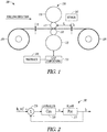
- FIG. 1 A schematic of a metal rolling mill with thickness control is shown at 100 in FIG. 1 .
- Incoming material of thickness H is provided by a roll 105 of material that reduced through a multiplicity of rolls 110, 115, 120, and 125 (referred to as a stand 130) turning at a known speed ⁇ r and collected by a roll 106.
- the stand 130 is equipped with a gap positioning system 135, which may be mechanical, hydraulic or a combination of both and may be controlled by a feedback device 140.
- the control objective is to regulate this outgoing thickness h as closely as possible to the target h ref .
- Many different sensors 145 may be used to measure thickness, with common devices including x-ray type gauges.
- the control problem is significantly complicated by the presence of a (varying) transportation delay between and exit thickness measurement device, sensor 145, and the stand 130.
- This time varying transportation delay is characterized by the distance between stand centerline L and the stand speed ⁇ r . It is well known that such time delay can have a destabilizing effect on control behavior and therefore it is critical that the delay is considered at control design stage.
- Control structure 200 includes a controller 210 coupled to a representation of a plant or stand 215 corresponding to the hydraulic or gap positioning system 135 and thickness sensor to control the provision of sheet metal with measured thickness h, with a thickness feedback summed at 220 with a desired or reference thickness provided as input to the controller 210.
- PI proportional/integral
- a controller 310 is coupled to a plant 315, which also provides sheet metal of thickness h.
- the controller 310 is coupled to a model 320 of the plant, which models the plant to provide an expected thickness to both a delay block 325 and a summing block 330.
- the delay block 325 provides a delay commensurate with timing of the measured thickness h and results in subtraction of the modeled thickness from the measured thickness at 335.
- the result is feedback 340 that is also provided to the summing block 330 to provide a feedback value subtracted from a reference thickness at 345, which is then provided to the controller.
- Inferential sensing is a commonly used technique in control engineering.
- An inferential sensor uses information available from other measurements and process parameters to calculate an estimate of the quantity of interest.
- Typical motivations for construction of an inferential sensor are replacement of costly or impractical physical instrumentation or improvement of control performance through estimation of key (unmeasureable) process parameters.
- a Kalman Filter based on statistical inference, is a commonly used software algorithm for implementation of inferential sensing technology. In this case, a physical model of the process under consideration is combined with available process measurements to provide estimates of unmeasurable process parameters.
- Inferential sensing technology is widely used and widely misunderstood in metal rolling applications. Since the British iron and steel research association (BISRA) gauge was reported in the 1950's as a means of avoiding the influence of the time delay from stand to gauge, inferential sensing technology has become standard in most metal rolling automation solutions.
- BIOSRA British iron and steel research association
- the estimated thickness is used in either one of two ways. Firstly, the estimated exit thickness can be used to construct a feedback loop, similar to that shown in FIG. 2 . This observer based controller is shown generally at 400 in FIG. 4 , in which the estimated thickness feedback is provided at 410. Error! Reference source not found.
- the estimated thickness can be used to construct a feed-forward compensation, which is typically added to the compensation from the original feedback loop shown in FIG. 2 .
- This feed-forward correction can be derived as:
- This thickness estimate can then be used in a similar way as described with respect to FIG. 4 .
- internal disturbance modelling and compensation may be performed.
- Unmeasured, yet observable disturbances are of significant importance to thickness control in metal rolling applications. These disturbances are referred to as internal due to the fact that they manifest themselves on the internal states of the plant/model as opposed to appearing at either input/output directly.
- Reasons for such internal disturbances are typically non-uniform cylindrical grinding on the mill stand rolls, thermo-mechanical variation in the mill stand rolls and hydro-dynamic effects of Back-Up Roll bearings (depending on bearing type and construction).
- roll eccentricity is modeled and compensated.
- Roll eccentricity may be caused by grinding inaccuracies during the manufacture, or preparation of rolls for use, deviations between the axis of the roll barrel and the roll neck or by non-uniform thermal expansion.
- a simple schematic of eccentricity on a roll is shown at 500 in FIG. 5 as an actual roll shape shown by solid line 510 and an ideal roll shape as shown by broken line 515 which are effectively coaxial.
- the amount of eccentricity is shown at a maximum eccentricity, e, at 520 as a difference between the ideal and actual radius.
- Eccentricity compensation techniques can be broadly classified into two categories; passive and active. Passive compensation simply attempts to remove the gain effect described above in a mill-stretch compensation loop. Active compensation however generates a signal in the position or force control loop of the hydraulic positioning system in order to reduce the periodic disturbances in the strip.
- Design of inferential sensors for thickness control in metal rolling applications has been rather ad-hoc, utilizing a significant amount of engineer insight and experience.
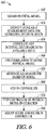
- a systematic approach may be used for inferential sensor design for thickness control in metal rolling applications as illustrated at 600 in a flow diagram of FIG. 6 .
- the first step in the Inferential Sensor construction workflow is modelling of a mill stand area as indicated at 610. Although this is valid for any type of mill (single stand, reversing or tandem), embodiments are described related to a mill with the geometry shown in FIG. 1 .
- Model components include a rolling model, an HGC model, and a main drive model.
- the strip exit gauge depends on the roll gap s, which is controlled by the hydraulic capsule, and on the mill stretch.
- the mill stretch is in a turn a non-linear function of the rolling force.
- a typical example of a stretch curve for a rolling mill stand is shown at 700 in FIG. 7 shown as mill stretch versus roll force.
- variable transport delay may be treated in the Kalman Filter implementation as a communication delay.
- the delay is at least partially a result of mill speed variations. Slower mill speed results in a larger delay, and faster mill speed results in a shorter delay of the thickness measurement.
- the user can select various internal disturbances to be estimated at 630, depending on the type of rolling application under consideration. Although this could in principle be extended to any type of internal disturbance model that affects exit gauge, currently selectable are
- the selected internal disturbances are then used to model the mill stand at 640, utilizing the available data.
- a Kalman filter is then generated based on the model at 650 and may be integrated into the controller at 660.
- the controller with the Kalman filter may be parameterized and the corresponding mill stand run to produce sheet metal.
- the available data may then be collected, including the actual sheet metal thickness measurements.
- the model may be adjusted by adjusting Kalman filter parameters based on the collected data, and the mill stand run again to ensure the model based controller is providing sheet metal of desired thickness.
- Robustness of inferential sensors may be strongly dependent on model quality.
- An example of this is model dynamics mismatch resulting in fake artifacts in inferred values.
- FIG. 8 is a block diagram illustrating a rolled sheet metal system generally at 800.
- System 800 includes a mill 810 that utilizes multiple rollers to produce sheet metal of a desired thickness from sheet metal stock.
- Multiple sensors 815 provide measured data regarding the system 800, such as actual sheet metal thickness produced, roller speeds, roller forces and other available measurements.
- the measured data is received at an input 820 of a controller 825.
- Controller 825 includes one or more processors and code stored on media readable by the one or more processors to control the thickness of the produced sheet metal.
- Controller 825 includes the input 820 that receives at least a measurement of sheet metal thickness that is time delayed from the production of the sheet metal.
- the controller also includes multiple models 830, 835 of the sheet metal mill.
- the sheet metal thickness is modeled as a communication delay.
- the communication delay is a function of a variable transport delay input since the thickness cannot be directly measured between the rollers.
- At least one of the models comprises an internal disturbance model based on one or more of the multiple measured data received at the input 820.
- the models are used to form a Kalman filter 840.
- An output 845 is coupled to the mill 810 to control a gap between the rolls that produce the rolled sheet metal.
- the multiple models include one or more of a rolling model with a corresponding input of roll torque, gap control model with a corresponding input of rolling force, and a main drive model with a corresponding input of roll speed.
- One or more internal disturbances that are modeled are selected from the group consisting of backup and work roll eccentricity, work roll thermal crown, work roll mechanical wear, and backup roll bearing flotation.
- the Kalman filter may include filter parameters adjusted as a function of measured mill parameter values from operation of the sheet metal mill.
- FIG. 9 is a block schematic diagram illustrating one example of thickness control for roll eccentricity compensation generally at 900.
- a mill is illustrated in block form at 910 including multiple rollers and hydraulic gap control (HGC) to change a gap between rollers that changes the thickness of an input sheet of metal 915 from a source roll of metal 920.
- the output sheet of metal 922 with changed thickness is collected on a collection roller 925.
- the thickness of the output sheet of metal is measured by a thickness sensor 930, positioned downstream from the mill 910.
- HGC hydraulic gap control
- the thickness measurement or exit gage in mm, h is provided to a Kalman Filter (KF) 935, which also receives measured parameters s, F, and v via 940 measured by corresponding sensors of the mill 910.
- S is the HGC position, or gap in mm.
- F is the rolling load in tons, and v is the mill speed in m/minute.
- the thickness estimation, h is provided to a summing junction 945 where it is combined with a reference thickness, href, corresponding to the desired thickness of the output sheet 922 and provided to a proportional/integral (PI) regulator 950 implementing a combination of proportional and integral control, C(s), to provide a control signal to a summing junction 955.
- PI proportional/integral
- Summing junction 550 combines the control signal with a feedforward eccentricity estimation ê from KF 935 to provide a position adjustment signal to the mill 910 to control the gap.
- control of the gap is based on estimates of both the thickness at the time the metal sheet is run through the roller gap and an estimate of feed forward eccentricity, both of which are provided by KF 935.
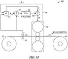
- FIG. 10 is a block schematic diagram illustrating an alternative example of thickness control for roll eccentricity compensation generally at 1000.
- the elements of FIG. 10 have reference numbers corresponding to those of FIG. 9 .
- the difference is that the summing junction 945 in FIG. 10 receives the measured thickness, h, direction from sensor 930 as opposed to receiving it from KF 935. Otherwise operations performed by thickness control 1000 are the same as those performed by thickness control 900.
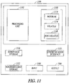
- FIG. 11 is a block schematic diagram of a computer system 1100 to implement the controller and methods according to example embodiments. All components need not be used in various embodiments.
- One example computing device in the form of a computer 1100 may include a processing unit 1102, memory 1103, removable storage 1110, and non-removable storage 1112.
- the example computing device is illustrated and described as computer 1100, the computing device may be in different forms in different embodiments.
- the computing device may instead be a smartphone, a tablet, smartwatch, or other computing device including the same or similar elements as illustrated and described with regard to FIG. 11 .
- Devices such as smartphones, tablets, and smartwatches are generally collectively referred to as mobile devices.
- the various data storage elements are illustrated as part of the computer 1100, the storage may also or alternatively include cloud-based storage accessible via a network, such as the Internet.
- Memory 1103 may include volatile memory 1114 and non-volatile memory 1108.
- Computer 1100 may include - or have access to a computing environment that includes - a variety of computer-readable media, such as volatile memory 1114 and non-volatile memory 1108, removable storage 1110 and non-removable storage 1112.
- Computer storage includes random access memory (RAM), read only memory (ROM), erasable programmable read-only memory (EPROM) & electrically erasable programmable read-only memory (EEPROM), flash memory or other memory technologies, compact disc read-only memory (CD ROM), Digital Versatile Disks (DVD) or other optical disk storage, magnetic cassettes, magnetic tape, magnetic disk storage or other magnetic storage devices capable of storing computer-readable instructions for execution to perform functions described herein.
- RAM random access memory
- ROM read only memory
- EPROM erasable programmable read-only memory
- EEPROM electrically erasable programmable read-only memory
- flash memory or other memory technologies
- Computer 1100 may include or have access to a computing environment that includes input 1106, output 1104, and a communication connection 1116.
- Output 1104 may include a display device, such as a touchscreen, that also may serve as an input device.
- the input 1106 may include one or more of a touchscreen, touchpad, mouse, keyboard, camera, one or more device-specific buttons, one or more sensors integrated within or coupled via wired or wireless data connections to the computer 1100, and other input devices.
- the computer may operate in a networked environment using a communication connection to connect to one or more remote computers, such as database servers, including cloud based servers and storage.
- the remote computer may include a personal computer (PC), server, router, network PC, a peer device or other common network node, or the like.
- the communication connection may include a Local Area Network (LAN), a Wide Area Network (WAN), cellular, WiFi, Bluetooth, or other networks.
- Computer-readable instructions stored on a computer-readable storage device are executable by the processing unit 1102 of the computer 1100.
- a hard drive, CD-ROM, and RAM are some examples of articles including a non-transitory computer-readable medium such as a storage device.
- the terms computer-readable medium and storage device do not include carrier waves.
- a computer program 1118 may be used to cause processing unit 1102 to perform one or more methods or algorithms described herein.
- Example 1 includes a rolled sheet metal mill controller for controlling thickness of sheet metal produced by rolls of the mill, the controller comprising one or more processors and code stored on media readable by the one or more processors to control the thickness of the produced sheet metal, the controller including an input coupled to receive multiple measured mill parameters including produced sheet metal thickness that is time delayed from the production of the sheet metal, multiple models of the sheet metal mill, wherein the sheet metal thickness is modeled as an input varying delay, and at least one internal disturbance model based on one or more of the multiple measured parameters coupled to the input, a Kalman filter based on the multiple models, and an output coupled to control a gap between the rolls that produce the rolled sheet metal.
- the controller comprising one or more processors and code stored on media readable by the one or more processors to control the thickness of the produced sheet metal
- the controller including an input coupled to receive multiple measured mill parameters including produced sheet metal thickness that is time delayed from the production of the sheet metal, multiple models of the sheet metal mill, wherein the sheet metal thickness is modeled as an input varying delay,
- Example 2 includes the rolled sheet metal mill of example 1 wherein the multiple models include a rolling model with a corresponding input of roll torque.
- Example 3 includes the rolled sheet metal mill of any of examples 1-2 wherein the multiple models include a gap control model with a corresponding input of rolling force.
- Example 4 includes the rolled sheet metal mill of any of examples 1 - 3 wherein the multiple models include a main drive model with a corresponding input of roll speed.
- Example 5 includes the rolled sheet metal mill of any of examples 1 - 4 wherein the communication delay is a function of a variable transport delay input.
- Example 6 includes the rolled sheet metal mill of any of examples 1 - 5 wherein one or more internal disturbances that are modeled are selected from the group consisting of backup and work roll eccentricity, work roll thermal crown, work roll mechanical wear, and backup roll bearing flotation.
- Example 7 includes the rolled sheet metal mill of any of examples 1 - 6 wherein the Kalman filter is based on the models and is robust to known parametric uncertainties.
- Example 8 includes the rolled sheet metal mill of any of examples 1-7 wherein the Kalman filter includes filter parameters adjusted as a function of measured mill parameter values from operation of the sheet metal mill.
- a method of programming a controller for a rolled sheet metal mill including obtaining a physical representation of the rolled sheet metal mill, identifying available measurements for generating inferential estimates of internal states of the rolled sheet metal mill, correlating key internal disturbances to the available measurements to model the rolled sheet metal mill, generating a Kalman filter based on the model, and adding the Kalman filter to the controller such that the controller is programmed to provide closed loop control thickness of sheet metal produced by the sheet metal mill.
- Example 10 includes the method of example 9 and further comprising testing the controller as a function of operation of the rolled sheet metal mill.
- Example 11 includes the method of example 10 and further comprising adjusting Kalman filter parameters responsive to the testing.
- Example 12 includes the method of any of examples 10-11 wherein the multiple models include a rolling model with a corresponding input of roll torque.
- Example 13 includes the method of any of examples 10-12 wherein the multiple models include a gap control model with a corresponding input of rolling force.
- Example 14 includes the method of any of examples 10-13 wherein the multiple models include a main drive model with a corresponding input of roll speed.
- Example 15 includes the method of any of examples 10-14 wherein the communication delay is a function of a variable transport delay input.
- Example 16 includes the method of any of examples 10-15 wherein one or more internal disturbances that are modeled are selected from the group consisting of backup and work roll eccentricity, work roll thermal crown, work roll mechanical wear, and backup roll bearing flotation.
- a rolled sheet metal mill controller including a processor, a sensor, and a memory device coupled to the processor and having a program stored thereon for execution by the program processor to receive an input of multiple measured mill parameters from the sensor including produced sheet metal thickness that is time delayed from the production of the sheet metal, process multiple models of the sheet metal mill, wherein the sheet metal thickness is modeled as an input varying delay, and at least one internal disturbance model based on one or more of the multiple measured parameters coupled to the input, execute a Kalman filter based on the multiple models, and provide an output coupled to control a gap between the rolls that produce the rolled sheet metal.
- Example 18 includes the controller of example 17 wherein the multiple models include a rolling model with a corresponding input of roll torque, a gap control model with a corresponding input of rolling force, and a main drive model with a corresponding input of roll speed.
- the multiple models include a rolling model with a corresponding input of roll torque, a gap control model with a corresponding input of rolling force, and a main drive model with a corresponding input of roll speed.
- Example 19 includes the controller of any of examples 17-18 wherein the communication delay is a function of a variable transport delay input.
- Example 20 includes the controller of any of examples 17-19 wherein one or more internal disturbances that are modeled are selected from the group consisting of backup and work roll eccentricity, work roll thermal crown, work roll mechanical wear, and backup roll bearing flotation.
Landscapes
- Engineering & Computer Science (AREA)
- Mechanical Engineering (AREA)
- Control Of Metal Rolling (AREA)
- Feedback Control In General (AREA)
Abstract
Description
- When rolling metal into sheets, the thickness of the resulting sheet is difficult to control. A rolling mill stand typically has four or more rolls mounted in a vertical plane with two smaller diameter work rolls supported between larger-diameter back-up rolls.
- Centerline thickness (gage) deviation is arguably the most important Key Performance Indicator (KPI) in any metal rolling application (ferrous, nonferrous metals, hot or cold rolling). Despite the relative maturity of the metal rolling process and indeed the control technology that is adopted, mill operators constantly strive for improved process performance. Indeed this is driven, in part, by the ultra-competitive economic market conditions in the metals industry in general.
- There are many challenges to design of robust yet high performance thickness control strategies. The main challenges range from the presence of varying time delays between a mill stand and measurement device, to significant nonlinearities across the operating range. Furthermore, the requirement of fast disturbance rejection of measured disturbances such as entry thickness and entry speed or un-measured internal disturbances such as roll eccentricity, thermal growth and thermo-mechanical wear of work rolls presents a further challenge. Although each of these challenges are well known and reasonably well understood, there is a lack of a coordinated and systematic approach to thickness control design, which can incorporate all of the above features effectively.
- A rolled sheet metal mill controller for controlling thickness of sheet metal produced by rolls of the mill, the controller comprising one or more processors and code stored on media readable by the one or more processors to control the thickness of the produced sheet metal, the controller including an input coupled to receive multiple measured mill parameters including produced sheet metal thickness that is time delayed from the production of the sheet metal, multiple models of the sheet metal mill, wherein the sheet metal thickness is modeled as an input varying delay, and at least one internal disturbance model based on one or more of the multiple measured parameters coupled to the input, a Kalman filter based on the multiple models, and an output coupled to control a gap between the rolls that produce the rolled sheet metal.
- A method of programming a controller for a rolled sheet metal mill, the method including obtaining a physical representation of the rolled sheet metal mill, identifying available measurements for generating inferential estimates of internal states of the rolled sheet metal mill, correlating key internal disturbances to the available measurements to model the rolled sheet metal mill, generating a Kalman filter based on the model, and adding the Kalman filter to the controller such that the controller is programmed to provide closed loop control thickness of sheet metal produced by the sheet metal mill.
- A rolled sheet metal mill controller including a processor, a sensor, and a memory device coupled to the processor and having a program stored thereon for execution by the program processor to receive an input of multiple measured mill parameters from the sensor including produced sheet metal thickness that is time delayed from the production of the sheet metal, process multiple models of the sheet metal mill, wherein the sheet metal thickness is modeled as an input varying delay, and at least one internal disturbance model based on one or more of the multiple measured parameters coupled to the input, execute a Kalman filter based on the multiple models, and provide an output coupled to control a gap between the rolls that produce the rolled sheet metal.
-
-
FIG. 1 is a block diagram of a sheet metal rolling stand with model based thickness control according to an example embodiment. -
FIG. 2 is a block flow diagram illustrating a sheet metal thickness control mechanism according to an example embodiment. -
FIG. 3 is a block flow diagram illustrating a sheet metal thickness control mechanism according to an example embodiment. -
FIG. 4 is a block flow diagram illustrating a sheet metal thickness control mechanism according to an example embodiment. -
FIG. 5 is a block diagram schematic representation of an ideal and actual roll superimposed to show eccentricities according to an example embodiment. -
FIG. 6 is a flowchart illustrating a method of creating a thickness controller for a sheet metal mill according to an example embodiment. -
FIG. 7 is a graph of a stretch curve for a rolling mill stand shown as mill stretch versus roll force according to an example embodiment. -
FIG. 8 is a block diagram illustrating a rolled sheet metal system for inferentially sensing and controlling sheet metal thickness according to an example embodiment. -
FIG. 9 is a block schematic diagram illustrating one example of thickness control for roll eccentricity compensation according to an example embodiment. -
FIG. 10 is a block schematic diagram illustrating an alternative example of thickness control for roll eccentricity compensation according to an example embodiment. -
FIG. 11 is a block schematic diagram of a computer system to implement the controller and methods according to example embodiments. - In the following description, reference is made to the accompanying drawings that form a part hereof, and in which is shown by way of illustration specific embodiments which may be practiced. These embodiments are described in sufficient detail to enable those skilled in the art to practice the invention, and it is to be understood that other embodiments may be utilized and that structural, logical and electrical changes may be made without departing from the scope of the present invention. The following description of example embodiments is, therefore, not to be taken in a limited sense, and the scope of the present invention is defined by the appended claims.
- The functions or algorithms described herein may be implemented in software in one embodiment. The software may consist of computer executable instructions stored on computer readable media or computer readable storage device such as one or more non-transitory memories or other type of hardware based storage devices, either local or networked. Further, such functions correspond to modules, which may be software, hardware, firmware or any combination thereof. Multiple functions may be performed in one or more modules as desired, and the embodiments described are merely examples. The software may be executed on a digital signal processor, ASIC, microprocessor, or other type of processor operating on a computer system, such as a personal computer, server or other computer system, turning such computer system into a specifically programmed machine.
- A model based inferential sensor may be used in a controller for controlling sheet metal thickness utilizes internal disturbance modelling and compensation. In various embodiments, roll eccentricity is modeled and compensated for by a rolling model. An HGC (hydraulic gap control)_model accounts for mill stretch, which is a non-linear function of rolling force. A main drive model is used to model main drive dynamics. The models may be represented as a series of non-linear ordinary differential equations.
- In designing an inferential sensor, available measurements may be identified and written as a measured output function. Thickness measurement, which is available downstream from the mill stand is delayed, and may be modeled as a communication delay which is clearly varying with mill speed. With respect to the internal disturbance modeling, a user can select various internal disturbances to be modeled depending on the type of rolling application. A Kalman Filter may be used for systems with uncertain parameters. Parameter uncertainty may be incorporated in the Kalman Filter description with covariance updated accordingly.
- A physical model of the process under consideration may be combined with available process measurements to provide estimates of unmeasurable process parameters in order to control the thickness of metal produced via the mill stand. In one embodiment, a systematic approach to inferential sensor design, considers the influence of time delays, unmeasureable internal disturbances and parameter uncertainties.
- Although various embodiments described are focused on thickness, also referred to as gage, control in a single-stand, cold strip mill, it is anticipated that the inventive subject matter may be is applicable to any type of metal rolling application. A schematic of a metal rolling mill with thickness control is shown at 100 in
FIG. 1 . Incoming material of thickness H is provided by aroll 105 of material that reduced through a multiplicity ofrolls stand 130 is equipped with agap positioning system 135, which may be mechanical, hydraulic or a combination of both and may be controlled by afeedback device 140. The material leaves the stand at thickness h , which may be measured by a thickness measuring device,sensor 145, at a point indicated by arrows 150. The control objective is to regulate this outgoing thickness h as closely as possible to the target href . Manydifferent sensors 145 may be used to measure thickness, with common devices including x-ray type gauges. - The control problem is significantly complicated by the presence of a (varying) transportation delay between and exit thickness measurement device,
sensor 145, and thestand 130. This time varying transportation delay is characterized by the distance between stand centerline L and the stand speed ωr . It is well known that such time delay can have a destabilizing effect on control behavior and therefore it is critical that the delay is considered at control design stage. - One common, simple approach used is to directly deploy a proportional/integral (PI) regulator or controller to control thickness via hydraulic positioning system that controls the positioning of the rolls. As a consequence of the time delay, the controller is de-tuned therefore leading to closed loop performance with limited bandwidth. This simple control structure is shown in block diagram form in
FIG. 2 at 200.Control structure 200 includes acontroller 210 coupled to a representation of a plant or stand 215 corresponding to the hydraulic orgap positioning system 135 and thickness sensor to control the provision of sheet metal with measured thickness h, with a thickness feedback summed at 220 with a desired or reference thickness provided as input to thecontroller 210. - Slightly more advanced control techniques, incorporating delay compensation, have also been applied. An example of such delay compensation loop is the celebrated Smith Predictor, shown at 300 in
FIG. 3 . Although this delay compensation structure allows for improved closed loop bandwidth, it suffers from well-known issues related to robustness with respect to delay uncertainty. Acontroller 310 is coupled to aplant 315, which also provides sheet metal of thickness h. In addition, thecontroller 310 is coupled to amodel 320 of the plant, which models the plant to provide an expected thickness to both adelay block 325 and a summingblock 330. Thedelay block 325 provides a delay commensurate with timing of the measured thickness h and results in subtraction of the modeled thickness from the measured thickness at 335. The result isfeedback 340 that is also provided to the summingblock 330 to provide a feedback value subtracted from a reference thickness at 345, which is then provided to the controller. - Inferential sensing is a commonly used technique in control engineering. An inferential sensor uses information available from other measurements and process parameters to calculate an estimate of the quantity of interest. Typical motivations for construction of an inferential sensor are replacement of costly or impractical physical instrumentation or improvement of control performance through estimation of key (unmeasureable) process parameters. A Kalman Filter, based on statistical inference, is a commonly used software algorithm for implementation of inferential sensing technology. In this case, a physical model of the process under consideration is combined with available process measurements to provide estimates of unmeasurable process parameters.
- Inferential sensing technology is widely used and widely misunderstood in metal rolling applications. Since the British iron and steel research association (BISRA) gauge was reported in the 1950's as a means of avoiding the influence of the time delay from stand to gauge, inferential sensing technology has become standard in most metal rolling automation solutions.
- Despite the plethora of inferential sensor implementations that have been proposed, a systematic approach to inferential sensor design, considering the influence of time delays, unmeasureable internal disturbances and parameter uncertainties remains an open issue.
- In its simplest form, the BISRA gauge utilizes the fact that an expression for roll separating force can be written as

- Fr
- Roll Separating force [N]
- cg
- Stand modulus [N/m]
- h
- Exit Thickness [m]
- s
- HGC (hydraulic gap control) Screw Position [m]
- In one embodiment, both the roll separating force and HGC screw position are measured, which allows writing of the estimated exit thickness as:

- In a typical application of such a model, the estimated thickness is used in either one of two ways. Firstly, the estimated exit thickness can be used to construct a feedback loop, similar to that shown in
FIG. 2 . This observer based controller is shown generally at 400 inFIG. 4 , in which the estimated thickness feedback is provided at 410.Error! Reference source not found. - Secondly, the estimated thickness can be used to construct a feed-forward compensation, which is typically added to the compensation from the original feedback loop shown in
FIG. 2 . This feed-forward correction can be derived as: - Taking the derivative with respect to thickness:

- It is observed that


- The screw compensation may be rewritten as:

- Massflow control is based on the observation that massflow is conserved through a single stand. If it is assumed that there is no lateral spread (a reasonable assumption in hot strip finishing mill applications, or cold strip rolling applications), then it is possible to write the conservation of massflow in simplified form as

- V
- Entry Strip Speed [m/s]
- ν
- Exit Strip Speed [m/s]
- In this case it is assumed that the entry and exit strip speeds are measured using e.g. laser speed velocimeter. It is further assumed that the entry thickness is measured. It is therefore possible to write the thickness estimate as

- This thickness estimate can then be used in a similar way as described with respect to
FIG. 4 . - In one embodiment, internal disturbance modelling and compensation may be performed. Unmeasured, yet observable disturbances are of significant importance to thickness control in metal rolling applications. These disturbances are referred to as internal due to the fact that they manifest themselves on the internal states of the plant/model as opposed to appearing at either input/output directly. Reasons for such internal disturbances are typically non-uniform cylindrical grinding on the mill stand rolls, thermo-mechanical variation in the mill stand rolls and hydro-dynamic effects of Back-Up Roll bearings (depending on bearing type and construction).
- Roll Eccentricity Modelling and Compensation
- In one embodiment, roll eccentricity is modeled and compensated. Roll eccentricity may be caused by grinding inaccuracies during the manufacture, or preparation of rolls for use, deviations between the axis of the roll barrel and the roll neck or by non-uniform thermal expansion. A simple schematic of eccentricity on a roll is shown at 500 in
FIG. 5 as an actual roll shape shown bysolid line 510 and an ideal roll shape as shown bybroken line 515 which are effectively coaxial. The amount of eccentricity is shown at a maximum eccentricity, e, at 520 as a difference between the ideal and actual radius. - The effect of eccentricity on thickness in a rolling application can be explained as follows: Normally an increased force means the exit thickness has increased (thus pushing the rolls apart). However, if the rolls are eccentric then when the largest radius passes through the roll gap, the force increases, but the exit thickness actually decreases. Hence a change in force is misinterpreted when eccentricity components are present. This can be easily seen in the following, assuming that eccentricity signal e enters as follows

- Now, the estimate of the exit thickness is given as

- Hence it is clear that the controller would think that the eccentricity variations are disturbances in the output and try to compensate for them.
- The eccentricity signal may be modeled as a compound multi-sinusoidal signal with mutliple harmonics as follows

- e(t)
- Eccentricity signal
- aij
- Amplitude of jth harmonic of sinusoidal component i
- ωi
- Frequency of sinusoidal component i
- t
- Absolute time
- N
- Number of sinusoidal components
- H
- Number of harmonics of each sinusoidal component
- Eccentricity compensation techniques can be broadly classified into two categories; passive and active. Passive compensation simply attempts to remove the gain effect described above in a mill-stretch compensation loop. Active compensation however generates a signal in the position or force control loop of the hydraulic positioning system in order to reduce the periodic disturbances in the strip.
- Design of inferential sensors for thickness control in metal rolling applications has been rather ad-hoc, utilizing a significant amount of engineer insight and experience. In various embodiments, a systematic approach may be used for inferential sensor design for thickness control in metal rolling applications as illustrated at 600 in a flow diagram of
FIG. 6 . - The first step in the Inferential Sensor construction workflow is modelling of a mill stand area as indicated at 610. Although this is valid for any type of mill (single stand, reversing or tandem), embodiments are described related to a mill with the geometry shown in
FIG. 1 . Model components include a rolling model, an HGC model, and a main drive model. - A classical non-linear rolling model is used to simplify the roll contact area computations. This is of the form
- [Fr Pr fs ] T
- = f(H,h,k,R,W)
- Fr
- Rolling Load [N]
- Pr
- Rolling Torque [Nm]
- fs
- Forward Slip [-]
- k
- Material hardness [Pa]
- R
- Roll Radius [m]
- W
- Strip Width [m]
- As mentioned previously, the strip exit gauge depends on the roll gap s, which is controlled by the hydraulic capsule, and on the mill stretch. The mill stretch is in a turn a non-linear function of the rolling force. A typical example of a stretch curve for a rolling mill stand is shown at 700 in
FIG. 7 shown as mill stretch versus roll force. An expression for the exit thickness can then be written as
- Fs
- Mill Stretch [m]
- Note also that


- Sref
- HGC position reference [m]
- Thgc
- HGC Time constant [s]
- A simple model of the main drive dynamics is of the form

- νroll
- Work Roll Speed [m/s]
- νref
- Work Roll Speed Reference [m/s]
- Troll
- Main Drive Time constant [s]
- The model components are collected together and represented in compact form as a series of non-linear ordinary differential equations of the form


- x
- Dynamic states of the model
- u
- Model Inputs
- d
- Measured Disturbances
- th
- Estimatable parameters
- y
- Model Outputs
- In designing the inferential sensor, at 630 in
FIG. 6 , measurements that are available for estimation of the system state are determined. The measured output function may be expressed as:
- With respect to transport delay, L, modelling, in typical cases, a thickness measurement is available downstream from the mill stand. As a consequence of this measurement location, a variable transport delay is present on the output (if exit thickness is selected as a measured output of interest). An expression for this variable transport delay, L, is given as an integral implicit relationship:

- The variable transport delay may be treated in the Kalman Filter implementation as a communication delay. The delay is at least partially a result of mill speed variations. Slower mill speed results in a larger delay, and faster mill speed results in a shorter delay of the thickness measurement.
- For internal disturbance modelling, the user can select various internal disturbances to be estimated at 630, depending on the type of rolling application under consideration. Although this could in principle be extended to any type of internal disturbance model that affects exit gauge, currently selectable are
- Backup and Work Roll Eccentricity
- Work Roll Thermal Crown
- Work Roll Mechanical Wear
- Backup Roll Bearing Flotation
- The selected internal disturbances are then used to model the mill stand at 640, utilizing the available data. A Kalman filter is then generated based on the model at 650 and may be integrated into the controller at 660. At 670, the controller with the Kalman filter may be parameterized and the corresponding mill stand run to produce sheet metal. The available data may then be collected, including the actual sheet metal thickness measurements. At 680, the model may be adjusted by adjusting Kalman filter parameters based on the collected data, and the mill stand run again to ensure the model based controller is providing sheet metal of desired thickness.
- Robustness of inferential sensors may be strongly dependent on model quality. An example of this is model dynamics mismatch resulting in fake artifacts in inferred values.
- By assuming some parametric uncertainty in the model (e.g. stand module), and utilizing the concept of equivalent noise, one can design the Kalman filter which is robust to such parametric uncertainties.
-
FIG. 8 is a block diagram illustrating a rolled sheet metal system generally at 800.System 800 includes amill 810 that utilizes multiple rollers to produce sheet metal of a desired thickness from sheet metal stock.Multiple sensors 815 provide measured data regarding thesystem 800, such as actual sheet metal thickness produced, roller speeds, roller forces and other available measurements. The measured data is received at an input 820 of acontroller 825.Controller 825 includes one or more processors and code stored on media readable by the one or more processors to control the thickness of the produced sheet metal. -
Controller 825 includes the input 820 that receives at least a measurement of sheet metal thickness that is time delayed from the production of the sheet metal. The controller also includesmultiple models 830, 835 of the sheet metal mill. The sheet metal thickness is modeled as a communication delay. The communication delay is a function of a variable transport delay input since the thickness cannot be directly measured between the rollers. At least one of the models comprises an internal disturbance model based on one or more of the multiple measured data received at the input 820. In one embodiment, the models are used to form aKalman filter 840. Anoutput 845 is coupled to themill 810 to control a gap between the rolls that produce the rolled sheet metal. - In one embodiment, the multiple models include one or more of a rolling model with a corresponding input of roll torque, gap control model with a corresponding input of rolling force, and a main drive model with a corresponding input of roll speed. One or more internal disturbances that are modeled are selected from the group consisting of backup and work roll eccentricity, work roll thermal crown, work roll mechanical wear, and backup roll bearing flotation.
- The Kalman filter may include filter parameters adjusted as a function of measured mill parameter values from operation of the sheet metal mill.
-
FIG. 9 is a block schematic diagram illustrating one example of thickness control for roll eccentricity compensation generally at 900. A mill is illustrated in block form at 910 including multiple rollers and hydraulic gap control (HGC) to change a gap between rollers that changes the thickness of an input sheet ofmetal 915 from a source roll ofmetal 920. The output sheet ofmetal 922 with changed thickness is collected on acollection roller 925. The thickness of the output sheet of metal is measured by athickness sensor 930, positioned downstream from themill 910. Thus, the thickness measurement is made following the roller gap and at a time after actually pressing of the metal sheet that is variable, depending on the speed of the sheet progressing through the mill and the change in thickness. - The thickness measurement or exit gage in mm, h, is provided to a Kalman Filter (KF) 935, which also receives measured parameters s, F, and v via 940 measured by corresponding sensors of the
mill 910. S is the HGC position, or gap in mm. F is the rolling load in tons, and v is the mill speed in m/minute.KF 935 provides a thickness estimation,
junction 945 where it is combined with a reference thickness, href, corresponding to the desired thickness of theoutput sheet 922 and provided to a proportional/integral (PI)regulator 950 implementing a combination of proportional and integral control, C(s), to provide a control signal to a summingjunction 955. - Summing junction 550 combines the control signal with a feedforward eccentricity estimation ê from
KF 935 to provide a position adjustment signal to themill 910 to control the gap. Thus, control of the gap is based on estimates of both the thickness at the time the metal sheet is run through the roller gap and an estimate of feed forward eccentricity, both of which are provided byKF 935. -
FIG. 10 is a block schematic diagram illustrating an alternative example of thickness control for roll eccentricity compensation generally at 1000. The elements ofFIG. 10 have reference numbers corresponding to those ofFIG. 9 . The difference is that the summingjunction 945 inFIG. 10 receives the measured thickness, h, direction fromsensor 930 as opposed to receiving it fromKF 935. Otherwise operations performed bythickness control 1000 are the same as those performed bythickness control 900. -
FIG. 11 is a block schematic diagram of acomputer system 1100 to implement the controller and methods according to example embodiments. All components need not be used in various embodiments. One example computing device in the form of acomputer 1100, may include aprocessing unit 1102,memory 1103,removable storage 1110, andnon-removable storage 1112. Although the example computing device is illustrated and described ascomputer 1100, the computing device may be in different forms in different embodiments. For example, the computing device may instead be a smartphone, a tablet, smartwatch, or other computing device including the same or similar elements as illustrated and described with regard toFIG. 11 . Devices such as smartphones, tablets, and smartwatches are generally collectively referred to as mobile devices. Further, although the various data storage elements are illustrated as part of thecomputer 1100, the storage may also or alternatively include cloud-based storage accessible via a network, such as the Internet. -
Memory 1103 may includevolatile memory 1114 andnon-volatile memory 1108.Computer 1100 may include - or have access to a computing environment that includes - a variety of computer-readable media, such asvolatile memory 1114 andnon-volatile memory 1108,removable storage 1110 andnon-removable storage 1112. Computer storage includes random access memory (RAM), read only memory (ROM), erasable programmable read-only memory (EPROM) & electrically erasable programmable read-only memory (EEPROM), flash memory or other memory technologies, compact disc read-only memory (CD ROM), Digital Versatile Disks (DVD) or other optical disk storage, magnetic cassettes, magnetic tape, magnetic disk storage or other magnetic storage devices capable of storing computer-readable instructions for execution to perform functions described herein. -
Computer 1100 may include or have access to a computing environment that includes input 1106,output 1104, and acommunication connection 1116.Output 1104 may include a display device, such as a touchscreen, that also may serve as an input device. The input 1106 may include one or more of a touchscreen, touchpad, mouse, keyboard, camera, one or more device-specific buttons, one or more sensors integrated within or coupled via wired or wireless data connections to thecomputer 1100, and other input devices. The computer may operate in a networked environment using a communication connection to connect to one or more remote computers, such as database servers, including cloud based servers and storage. The remote computer may include a personal computer (PC), server, router, network PC, a peer device or other common network node, or the like. The communication connection may include a Local Area Network (LAN), a Wide Area Network (WAN), cellular, WiFi, Bluetooth, or other networks. - Computer-readable instructions stored on a computer-readable storage device are executable by the
processing unit 1102 of thecomputer 1100. A hard drive, CD-ROM, and RAM are some examples of articles including a non-transitory computer-readable medium such as a storage device. The terms computer-readable medium and storage device do not include carrier waves. For example, acomputer program 1118 may be used to causeprocessing unit 1102 to perform one or more methods or algorithms described herein. - Example 1 includes a rolled sheet metal mill controller for controlling thickness of sheet metal produced by rolls of the mill, the controller comprising one or more processors and code stored on media readable by the one or more processors to control the thickness of the produced sheet metal, the controller including an input coupled to receive multiple measured mill parameters including produced sheet metal thickness that is time delayed from the production of the sheet metal, multiple models of the sheet metal mill, wherein the sheet metal thickness is modeled as an input varying delay, and at least one internal disturbance model based on one or more of the multiple measured parameters coupled to the input, a Kalman filter based on the multiple models, and an output coupled to control a gap between the rolls that produce the rolled sheet metal.
- Example 2 includes the rolled sheet metal mill of example 1 wherein the multiple models include a rolling model with a corresponding input of roll torque.
- Example 3 includes the rolled sheet metal mill of any of examples 1-2 wherein the multiple models include a gap control model with a corresponding input of rolling force.
- Example 4 includes the rolled sheet metal mill of any of examples 1 - 3 wherein the multiple models include a main drive model with a corresponding input of roll speed.
- Example 5 includes the rolled sheet metal mill of any of examples 1 - 4 wherein the communication delay is a function of a variable transport delay input.
- Example 6 includes the rolled sheet metal mill of any of examples 1 - 5 wherein one or more internal disturbances that are modeled are selected from the group consisting of backup and work roll eccentricity, work roll thermal crown, work roll mechanical wear, and backup roll bearing flotation.
- Example 7 includes the rolled sheet metal mill of any of examples 1 - 6 wherein the Kalman filter is based on the models and is robust to known parametric uncertainties.
- Example 8 includes the rolled sheet metal mill of any of examples 1-7 wherein the Kalman filter includes filter parameters adjusted as a function of measured mill parameter values from operation of the sheet metal mill.
- In example 9, a method of programming a controller for a rolled sheet metal mill, the method including obtaining a physical representation of the rolled sheet metal mill, identifying available measurements for generating inferential estimates of internal states of the rolled sheet metal mill, correlating key internal disturbances to the available measurements to model the rolled sheet metal mill, generating a Kalman filter based on the model, and adding the Kalman filter to the controller such that the controller is programmed to provide closed loop control thickness of sheet metal produced by the sheet metal mill.
- Example 10 includes the method of example 9 and further comprising testing the controller as a function of operation of the rolled sheet metal mill.
- Example 11 includes the method of example 10 and further comprising adjusting Kalman filter parameters responsive to the testing.
- Example 12 includes the method of any of examples 10-11 wherein the multiple models include a rolling model with a corresponding input of roll torque.
- Example 13 includes the method of any of examples 10-12 wherein the multiple models include a gap control model with a corresponding input of rolling force.
- Example 14 includes the method of any of examples 10-13 wherein the multiple models include a main drive model with a corresponding input of roll speed.
- Example 15 includes the method of any of examples 10-14 wherein the communication delay is a function of a variable transport delay input.
- Example 16 includes the method of any of examples 10-15 wherein one or more internal disturbances that are modeled are selected from the group consisting of backup and work roll eccentricity, work roll thermal crown, work roll mechanical wear, and backup roll bearing flotation.
- In example 17, a rolled sheet metal mill controller including a processor, a sensor, and a memory device coupled to the processor and having a program stored thereon for execution by the program processor to receive an input of multiple measured mill parameters from the sensor including produced sheet metal thickness that is time delayed from the production of the sheet metal, process multiple models of the sheet metal mill, wherein the sheet metal thickness is modeled as an input varying delay, and at least one internal disturbance model based on one or more of the multiple measured parameters coupled to the input, execute a Kalman filter based on the multiple models, and provide an output coupled to control a gap between the rolls that produce the rolled sheet metal.
- Example 18 includes the controller of example 17 wherein the multiple models include a rolling model with a corresponding input of roll torque, a gap control model with a corresponding input of rolling force, and a main drive model with a corresponding input of roll speed.
- Example 19 includes the controller of any of examples 17-18 wherein the communication delay is a function of a variable transport delay input.
- Example 20 includes the controller of any of examples 17-19 wherein one or more internal disturbances that are modeled are selected from the group consisting of backup and work roll eccentricity, work roll thermal crown, work roll mechanical wear, and backup roll bearing flotation.
- Although a few embodiments have been described in detail above, other modifications are possible. For example, the logic flows depicted in the figures do not require the particular order shown, or sequential order, to achieve desirable results. Other steps may be provided, or steps may be eliminated, from the described flows, and other components may be added to, or removed from, the described systems. Other embodiments may be within the scope of the following claims.
Claims (15)
- A rolled sheet metal mill (910) controller (900) for controlling thickness of sheet metal (922) produced by rolls of the mill (910), the controller (900) comprising one or more processors (1102) and code (1118) stored on media (1103) readable by the one or more processors (1102) to control the thickness of the produced sheet metal (922), the controller (900) comprising:an input (940) coupled to receive multiple measured mill parameters including produced sheet metal thickness (930) that is time delayed from the production of the sheet metal (922);multiple models (935) of the sheet metal mill (910), wherein the sheet metal thickness is modeled as an input varying delay, and at least one internal disturbance model based on one or more of the multiple measured parameters coupled to the input (940);a Kalman filter (935) based on the multiple models; andan output (955) coupled to control a gap between the rolls (910) that produce the rolled sheet metal.
- The rolled sheet metal mill (910) of claim 1 wherein the multiple models (935) include a rolling model (500) with a corresponding input of roll torque.
- The rolled sheet metal mill (910) of claim 1 wherein the multiple models (935) include a gap control model with a corresponding input of rolling force.
- The rolled sheet metal mill (910) of claim 1 wherein the multiple models (935) include a main drive model with a corresponding input of roll speed.
- The rolled sheet metal mill (910) of any one of claims 1-4 wherein one or more internal disturbances that are modeled (935) are selected from the group consisting of backup and work roll eccentricity, work roll thermal crown, work roll mechanical wear, and backup roll bearing flotation.
- The rolled sheet metal mill (910) of any one of claims 1-4 wherein the Kalman filter (935) includes filter parameters adjusted as a function of measured mill parameter values from operation of the sheet metal mill.
- The rolled sheet metal mill (910) of any one of claims 1-4 wherein the controller (900) comprises:a processor (1102);a sensor (930); anda memory device (1103) coupled to the processor (1102) and having a program (1118) stored thereon for execution by the program processor (1102) to:receive the input (940);process multiple models (935);execute the Kalman filter (935) based on the multiple models; andprovide the output (955).
- A method of programming a controller (900) for a rolled sheet metal mill (910), the method comprising:obtaining (610) a physical representation of the rolled sheet metal mill;identifying (620) available measurements for generating inferential estimates of internal states of the rolled sheet metal mill;correlating (630) key internal disturbances to the available measurements to model the rolled sheet metal mill;generating (650) a Kalman filter (935) based on the model; andadding (660) the Kalman filter (935) to the controller (900) such that the controller (900) is programmed to provide closed loop control thickness of sheet metal (922) produced by the sheet metal mill (910).
- The method of claim 8 and further comprising testing the controller (900) as a function of operation of the rolled sheet metal mill (910).
- The method of claim 9 and further comprising adjusting Kalman filter (935) parameters responsive to the testing.
- The method of claim 9 wherein the multiple models (935) include a rolling model (935) with a corresponding input of roll torque, a gap control model (935) with a corresponding input of rolling force, and a main drive model (935) with a corresponding input of roll speed.
- The method of any one of claims 9-11 wherein the communication delay is a function of a variable transport delay input.
- The method of any one of claims 9-11 wherein one or more internal disturbances that are modeled are selected from the group consisting of backup and work roll eccentricity, work roll thermal crown, work roll mechanical wear, and backup roll bearing flotation.
- A computer readable medium having instructions for execution by a processor to perform operations for controlling a rolled sheet metal mill, the operations comprising:obtaining (610) a physical representation of the rolled sheet metal mill;identifying (620) available measurements for generating inferential estimates of internal states of the rolled sheet metal mill;correlating (630) key internal disturbances to the available measurements to model the rolled sheet metal mill;generating (650) a Kalman filter (935) based on the model; andadding (660) the Kalman filter (935) to the controller (900) such that the controller (900) is programmed to provide closed loop control thickness of sheet metal (922) produced by the sheet metal mill (910).
- The computer readable medium of claim 14 and further comprising testing the controller (900) as a function of operation of the rolled sheet metal mill (910), and wherein the multiple models (935) include a rolling model (935) with a corresponding input of roll torque, a gap control model (935) with a corresponding input of rolling force, and a main drive model (935) with a corresponding input of roll speed.
Applications Claiming Priority (1)
| Application Number | Priority Date | Filing Date | Title |
|---|---|---|---|
| US15/373,622 US20180161839A1 (en) | 2016-12-09 | 2016-12-09 | Metal thickness control model based inferential sensor |
Publications (2)
| Publication Number | Publication Date |
|---|---|
| EP3332883A1 true EP3332883A1 (en) | 2018-06-13 |
| EP3332883B1 EP3332883B1 (en) | 2020-05-06 |
Family
ID=60582411
Family Applications (1)
| Application Number | Title | Priority Date | Filing Date |
|---|---|---|---|
| EP17204486.9A Active EP3332883B1 (en) | 2016-12-09 | 2017-11-29 | Metal thickness control model based inferential sensor |
Country Status (3)
| Country | Link |
|---|---|
| US (1) | US20180161839A1 (en) |
| EP (1) | EP3332883B1 (en) |
| CN (1) | CN108213085B (en) |
Cited By (2)
| Publication number | Priority date | Publication date | Assignee | Title |
|---|---|---|---|---|
| EP3936248A1 (en) | 2020-07-07 | 2022-01-12 | Primetals Technologies Germany GmbH | Rolling taking into account frequency behaviour |
| EP3974073A1 (en) | 2020-09-28 | 2022-03-30 | Primetals Technologies Germany GmbH | Rolling taking into account frequency behaviour |
Families Citing this family (3)
| Publication number | Priority date | Publication date | Assignee | Title |
|---|---|---|---|---|
| CN115990615B (en) * | 2021-10-20 | 2024-04-05 | 宁德时代新能源科技股份有限公司 | Control method and device of roller press and roller press |
| US20240299997A1 (en) | 2023-03-10 | 2024-09-12 | Honeywell International Inc. | Dynamic Roll Eccentricity Identification Using Extended Kalman Filter State Estimation and Control Upgrade for Cold Rolling Mills |
| CN116393522B (en) * | 2023-03-27 | 2024-03-22 | 西安艾蒙希科技有限公司 | Thickness processing system of open-type four-column twenty-roller mill |
Citations (4)
| Publication number | Priority date | Publication date | Assignee | Title |
|---|---|---|---|---|
| JPS5825807A (en) * | 1981-08-10 | 1983-02-16 | Nippon Steel Corp | Controlling method of sheet thickness in strip rolling |
| JPS61193716A (en) * | 1985-02-25 | 1986-08-28 | Nippon Steel Corp | Control method of rolled plate thickness of strip |
| DE102006008574A1 (en) * | 2006-02-22 | 2007-08-30 | Siemens Ag | Reducing the influence of roller excentricity on the thickness of a rolled material, comprises identifying the roller excentricity and determining a correction signal for a control unit |
| US20090138102A1 (en) * | 2005-12-30 | 2009-05-28 | Per-Erik Moden | Method and device for tuning and control |
Family Cites Families (1)
| Publication number | Priority date | Publication date | Assignee | Title |
|---|---|---|---|---|
| US6263714B1 (en) * | 1999-12-27 | 2001-07-24 | Telepro, Inc. | Periodic gauge deviation compensation system |
-
2016
- 2016-12-09 US US15/373,622 patent/US20180161839A1/en not_active Abandoned
-
2017
- 2017-11-29 EP EP17204486.9A patent/EP3332883B1/en active Active
- 2017-12-08 CN CN201711289879.6A patent/CN108213085B/en active Active
Patent Citations (4)
| Publication number | Priority date | Publication date | Assignee | Title |
|---|---|---|---|---|
| JPS5825807A (en) * | 1981-08-10 | 1983-02-16 | Nippon Steel Corp | Controlling method of sheet thickness in strip rolling |
| JPS61193716A (en) * | 1985-02-25 | 1986-08-28 | Nippon Steel Corp | Control method of rolled plate thickness of strip |
| US20090138102A1 (en) * | 2005-12-30 | 2009-05-28 | Per-Erik Moden | Method and device for tuning and control |
| DE102006008574A1 (en) * | 2006-02-22 | 2007-08-30 | Siemens Ag | Reducing the influence of roller excentricity on the thickness of a rolled material, comprises identifying the roller excentricity and determining a correction signal for a control unit |
Cited By (5)
| Publication number | Priority date | Publication date | Assignee | Title |
|---|---|---|---|---|
| EP3936248A1 (en) | 2020-07-07 | 2022-01-12 | Primetals Technologies Germany GmbH | Rolling taking into account frequency behaviour |
| WO2022008133A1 (en) | 2020-07-07 | 2022-01-13 | Primetals Technologies Germany Gmbh | Rolling taking frequency behaviour into account |
| EP3936248B1 (en) | 2020-07-07 | 2023-10-25 | Primetals Technologies Germany GmbH | Rolling taking into account frequency behaviour |
| EP3974073A1 (en) | 2020-09-28 | 2022-03-30 | Primetals Technologies Germany GmbH | Rolling taking into account frequency behaviour |
| EP3974073B1 (en) | 2020-09-28 | 2023-07-19 | Primetals Technologies Germany GmbH | Rolling taking into account frequency behaviour |
Also Published As
| Publication number | Publication date |
|---|---|
| CN108213085B (en) | 2020-07-07 |
| US20180161839A1 (en) | 2018-06-14 |
| EP3332883B1 (en) | 2020-05-06 |
| CN108213085A (en) | 2018-06-29 |
Similar Documents
| Publication | Publication Date | Title |
|---|---|---|
| EP3332883B1 (en) | Metal thickness control model based inferential sensor | |
| JP6672094B2 (en) | Plant control device, rolling control device, plant control method, and plant control program | |
| Bemporad et al. | Optimization-based automatic flatness control in cold tandem rolling | |
| Park et al. | Prediction for manufacturing factors in a steel plate rolling smart factory using data clustering-based machine learning | |
| JP6404195B2 (en) | PLANT CONTROL DEVICE, ROLLING CONTROL DEVICE, PLANT CONTROL METHOD, AND PLANT CONTROL PROGRAM | |
| Jelali | Performance assessment of control systems in rolling mills–application to strip thickness and flatness control | |
| Shardt et al. | Modelling the strip thickness in hot steel rolling mills using least‐squares support vector machines | |
| Wang et al. | Adaptive calculation of deformation resistance model of online process control in tandem cold mill | |
| Prinz et al. | Online parameter estimation for adaptive feedforward control of the strip thickness in a hot strip rolling mill | |
| JPWO2015029171A1 (en) | Thickness control device for rolling mill | |
| CN111132773B (en) | Flatness control using optimizer | |
| JP6324259B2 (en) | Rolling control device, rolling control method, and rolling control program | |
| Nikitina et al. | Algorithm of robust control for multi-stand rolling mill strip based on stochastic multi-swarm multi-agent optimization | |
| Kucsera et al. | Hot rolling mill hydraulic gap control (HGC) thickness control improvement | |
| JP2007061876A (en) | Method for controlling thickness in cold tandem rolling | |
| CN108971237B (en) | Bearing float compensation for metal rolling applications | |
| Pittner et al. | Optimal control of tandem cold rolling using a pointwise linear quadratic technique with trims | |
| JP2022032344A (en) | Plant control device, rolling control device, plant control method, and plant control program | |
| JP2021133415A (en) | Model learning method, flying plate thickness changing method, steel plate manufacturing method, model learning device, flying plate thickness changing device and steel plate manufacturing device | |
| Schulte et al. | Adaptive Pass Scheduling for Roughness Control in Cold Rolling | |
| EP4427858A2 (en) | Dynamic roll eccentricity identification using extended kalman filter state estimation and control upgrade for cold rolling mills | |
| Zhang et al. | An expert PI controller with dead time compensation of monitor AGC in hot strip mill | |
| Gálvez et al. | A model-based predictive control scheme for steal rolling mills using neural networks | |
| JPH0413411A (en) | Method for controlling strip thickness when strip is passed through in hot continuous mill | |
| Degtev et al. | Stabilization of Strip Thickness in Nonstationary Stages of the Cold Rolling Process on a Multi-Stand Mill |
Legal Events
| Date | Code | Title | Description |
|---|---|---|---|
| PUAI | Public reference made under article 153(3) epc to a published international application that has entered the european phase |
Free format text: ORIGINAL CODE: 0009012 |
|
| STAA | Information on the status of an ep patent application or granted ep patent |
Free format text: STATUS: REQUEST FOR EXAMINATION WAS MADE |
|
| 17P | Request for examination filed |
Effective date: 20171129 |
|
| AK | Designated contracting states |
Kind code of ref document: A1 Designated state(s): AL AT BE BG CH CY CZ DE DK EE ES FI FR GB GR HR HU IE IS IT LI LT LU LV MC MK MT NL NO PL PT RO RS SE SI SK SM TR |
|
| AX | Request for extension of the european patent |
Extension state: BA ME |
|
| STAA | Information on the status of an ep patent application or granted ep patent |
Free format text: STATUS: EXAMINATION IS IN PROGRESS |
|
| 17Q | First examination report despatched |
Effective date: 20190402 |
|
| GRAP | Despatch of communication of intention to grant a patent |
Free format text: ORIGINAL CODE: EPIDOSNIGR1 |
|
| STAA | Information on the status of an ep patent application or granted ep patent |
Free format text: STATUS: GRANT OF PATENT IS INTENDED |
|
| INTG | Intention to grant announced |
Effective date: 20200103 |
|
| GRAS | Grant fee paid |
Free format text: ORIGINAL CODE: EPIDOSNIGR3 |
|
| GRAL | Information related to payment of fee for publishing/printing deleted |
Free format text: ORIGINAL CODE: EPIDOSDIGR3 |
|
| GRAS | Grant fee paid |
Free format text: ORIGINAL CODE: EPIDOSNIGR3 |
|
| GRAA | (expected) grant |
Free format text: ORIGINAL CODE: 0009210 |
|
| STAA | Information on the status of an ep patent application or granted ep patent |
Free format text: STATUS: THE PATENT HAS BEEN GRANTED |
|
| AK | Designated contracting states |
Kind code of ref document: B1 Designated state(s): AL AT BE BG CH CY CZ DE DK EE ES FI FR GB GR HR HU IE IS IT LI LT LU LV MC MK MT NL NO PL PT RO RS SE SI SK SM TR |
|
| REG | Reference to a national code |
Ref country code: GB Ref legal event code: FG4D |
|
| REG | Reference to a national code |
Ref country code: CH Ref legal event code: EP Ref country code: AT Ref legal event code: REF Ref document number: 1265959 Country of ref document: AT Kind code of ref document: T Effective date: 20200515 |
|
| REG | Reference to a national code |
Ref country code: IE Ref legal event code: FG4D |
|
| REG | Reference to a national code |
Ref country code: DE Ref legal event code: R096 Ref document number: 602017016140 Country of ref document: DE |
|
| REG | Reference to a national code |
Ref country code: NL Ref legal event code: FP |
|
| REG | Reference to a national code |
Ref country code: LT Ref legal event code: MG4D |
|
| PG25 | Lapsed in a contracting state [announced via postgrant information from national office to epo] |
Ref country code: IS Free format text: LAPSE BECAUSE OF FAILURE TO SUBMIT A TRANSLATION OF THE DESCRIPTION OR TO PAY THE FEE WITHIN THE PRESCRIBED TIME-LIMIT Effective date: 20200906 Ref country code: PT Free format text: LAPSE BECAUSE OF FAILURE TO SUBMIT A TRANSLATION OF THE DESCRIPTION OR TO PAY THE FEE WITHIN THE PRESCRIBED TIME-LIMIT Effective date: 20200907 Ref country code: GR Free format text: LAPSE BECAUSE OF FAILURE TO SUBMIT A TRANSLATION OF THE DESCRIPTION OR TO PAY THE FEE WITHIN THE PRESCRIBED TIME-LIMIT Effective date: 20200807 Ref country code: LT Free format text: LAPSE BECAUSE OF FAILURE TO SUBMIT A TRANSLATION OF THE DESCRIPTION OR TO PAY THE FEE WITHIN THE PRESCRIBED TIME-LIMIT Effective date: 20200506 Ref country code: SE Free format text: LAPSE BECAUSE OF FAILURE TO SUBMIT A TRANSLATION OF THE DESCRIPTION OR TO PAY THE FEE WITHIN THE PRESCRIBED TIME-LIMIT Effective date: 20200506 Ref country code: NO Free format text: LAPSE BECAUSE OF FAILURE TO SUBMIT A TRANSLATION OF THE DESCRIPTION OR TO PAY THE FEE WITHIN THE PRESCRIBED TIME-LIMIT Effective date: 20200806 Ref country code: FI Free format text: LAPSE BECAUSE OF FAILURE TO SUBMIT A TRANSLATION OF THE DESCRIPTION OR TO PAY THE FEE WITHIN THE PRESCRIBED TIME-LIMIT Effective date: 20200506 |
|
| PG25 | Lapsed in a contracting state [announced via postgrant information from national office to epo] |
Ref country code: BG Free format text: LAPSE BECAUSE OF FAILURE TO SUBMIT A TRANSLATION OF THE DESCRIPTION OR TO PAY THE FEE WITHIN THE PRESCRIBED TIME-LIMIT Effective date: 20200806 Ref country code: LV Free format text: LAPSE BECAUSE OF FAILURE TO SUBMIT A TRANSLATION OF THE DESCRIPTION OR TO PAY THE FEE WITHIN THE PRESCRIBED TIME-LIMIT Effective date: 20200506 Ref country code: HR Free format text: LAPSE BECAUSE OF FAILURE TO SUBMIT A TRANSLATION OF THE DESCRIPTION OR TO PAY THE FEE WITHIN THE PRESCRIBED TIME-LIMIT Effective date: 20200506 Ref country code: RS Free format text: LAPSE BECAUSE OF FAILURE TO SUBMIT A TRANSLATION OF THE DESCRIPTION OR TO PAY THE FEE WITHIN THE PRESCRIBED TIME-LIMIT Effective date: 20200506 |
|
| REG | Reference to a national code |
Ref country code: AT Ref legal event code: MK05 Ref document number: 1265959 Country of ref document: AT Kind code of ref document: T Effective date: 20200506 |
|
| PG25 | Lapsed in a contracting state [announced via postgrant information from national office to epo] |
Ref country code: AL Free format text: LAPSE BECAUSE OF FAILURE TO SUBMIT A TRANSLATION OF THE DESCRIPTION OR TO PAY THE FEE WITHIN THE PRESCRIBED TIME-LIMIT Effective date: 20200506 |
|
| PG25 | Lapsed in a contracting state [announced via postgrant information from national office to epo] |
Ref country code: DK Free format text: LAPSE BECAUSE OF FAILURE TO SUBMIT A TRANSLATION OF THE DESCRIPTION OR TO PAY THE FEE WITHIN THE PRESCRIBED TIME-LIMIT Effective date: 20200506 Ref country code: AT Free format text: LAPSE BECAUSE OF FAILURE TO SUBMIT A TRANSLATION OF THE DESCRIPTION OR TO PAY THE FEE WITHIN THE PRESCRIBED TIME-LIMIT Effective date: 20200506 Ref country code: EE Free format text: LAPSE BECAUSE OF FAILURE TO SUBMIT A TRANSLATION OF THE DESCRIPTION OR TO PAY THE FEE WITHIN THE PRESCRIBED TIME-LIMIT Effective date: 20200506 Ref country code: ES Free format text: LAPSE BECAUSE OF FAILURE TO SUBMIT A TRANSLATION OF THE DESCRIPTION OR TO PAY THE FEE WITHIN THE PRESCRIBED TIME-LIMIT Effective date: 20200506 Ref country code: IT Free format text: LAPSE BECAUSE OF FAILURE TO SUBMIT A TRANSLATION OF THE DESCRIPTION OR TO PAY THE FEE WITHIN THE PRESCRIBED TIME-LIMIT Effective date: 20200506 Ref country code: RO Free format text: LAPSE BECAUSE OF FAILURE TO SUBMIT A TRANSLATION OF THE DESCRIPTION OR TO PAY THE FEE WITHIN THE PRESCRIBED TIME-LIMIT Effective date: 20200506 Ref country code: CZ Free format text: LAPSE BECAUSE OF FAILURE TO SUBMIT A TRANSLATION OF THE DESCRIPTION OR TO PAY THE FEE WITHIN THE PRESCRIBED TIME-LIMIT Effective date: 20200506 Ref country code: SM Free format text: LAPSE BECAUSE OF FAILURE TO SUBMIT A TRANSLATION OF THE DESCRIPTION OR TO PAY THE FEE WITHIN THE PRESCRIBED TIME-LIMIT Effective date: 20200506 |
|
| REG | Reference to a national code |
Ref country code: DE Ref legal event code: R097 Ref document number: 602017016140 Country of ref document: DE |
|
| PG25 | Lapsed in a contracting state [announced via postgrant information from national office to epo] |
Ref country code: SK Free format text: LAPSE BECAUSE OF FAILURE TO SUBMIT A TRANSLATION OF THE DESCRIPTION OR TO PAY THE FEE WITHIN THE PRESCRIBED TIME-LIMIT Effective date: 20200506 Ref country code: PL Free format text: LAPSE BECAUSE OF FAILURE TO SUBMIT A TRANSLATION OF THE DESCRIPTION OR TO PAY THE FEE WITHIN THE PRESCRIBED TIME-LIMIT Effective date: 20200506 |
|
| PLBE | No opposition filed within time limit |
Free format text: ORIGINAL CODE: 0009261 |
|
| STAA | Information on the status of an ep patent application or granted ep patent |
Free format text: STATUS: NO OPPOSITION FILED WITHIN TIME LIMIT |
|
| 26N | No opposition filed |
Effective date: 20210209 |
|
| PG25 | Lapsed in a contracting state [announced via postgrant information from national office to epo] |
Ref country code: SI Free format text: LAPSE BECAUSE OF FAILURE TO SUBMIT A TRANSLATION OF THE DESCRIPTION OR TO PAY THE FEE WITHIN THE PRESCRIBED TIME-LIMIT Effective date: 20200506 |
|
| PG25 | Lapsed in a contracting state [announced via postgrant information from national office to epo] |
Ref country code: MC Free format text: LAPSE BECAUSE OF FAILURE TO SUBMIT A TRANSLATION OF THE DESCRIPTION OR TO PAY THE FEE WITHIN THE PRESCRIBED TIME-LIMIT Effective date: 20200506 |
|
| REG | Reference to a national code |
Ref country code: CH Ref legal event code: PL |
|
| PG25 | Lapsed in a contracting state [announced via postgrant information from national office to epo] |
Ref country code: LU Free format text: LAPSE BECAUSE OF NON-PAYMENT OF DUE FEES Effective date: 20201129 |
|
| REG | Reference to a national code |
Ref country code: BE Ref legal event code: MM Effective date: 20201130 |
|
| PG25 | Lapsed in a contracting state [announced via postgrant information from national office to epo] |
Ref country code: LI Free format text: LAPSE BECAUSE OF NON-PAYMENT OF DUE FEES Effective date: 20201130 Ref country code: CH Free format text: LAPSE BECAUSE OF NON-PAYMENT OF DUE FEES Effective date: 20201130 |
|
| REG | Reference to a national code |
Ref country code: IE Ref legal event code: MM4A |
|
| PG25 | Lapsed in a contracting state [announced via postgrant information from national office to epo] |
Ref country code: IE Free format text: LAPSE BECAUSE OF NON-PAYMENT OF DUE FEES Effective date: 20201129 Ref country code: FR Free format text: LAPSE BECAUSE OF NON-PAYMENT OF DUE FEES Effective date: 20201130 |
|
| PG25 | Lapsed in a contracting state [announced via postgrant information from national office to epo] |
Ref country code: TR Free format text: LAPSE BECAUSE OF FAILURE TO SUBMIT A TRANSLATION OF THE DESCRIPTION OR TO PAY THE FEE WITHIN THE PRESCRIBED TIME-LIMIT Effective date: 20200506 Ref country code: MT Free format text: LAPSE BECAUSE OF FAILURE TO SUBMIT A TRANSLATION OF THE DESCRIPTION OR TO PAY THE FEE WITHIN THE PRESCRIBED TIME-LIMIT Effective date: 20200506 Ref country code: CY Free format text: LAPSE BECAUSE OF FAILURE TO SUBMIT A TRANSLATION OF THE DESCRIPTION OR TO PAY THE FEE WITHIN THE PRESCRIBED TIME-LIMIT Effective date: 20200506 |
|
| PG25 | Lapsed in a contracting state [announced via postgrant information from national office to epo] |
Ref country code: MK Free format text: LAPSE BECAUSE OF FAILURE TO SUBMIT A TRANSLATION OF THE DESCRIPTION OR TO PAY THE FEE WITHIN THE PRESCRIBED TIME-LIMIT Effective date: 20200506 |
|
| GBPC | Gb: european patent ceased through non-payment of renewal fee |
Effective date: 20211129 |
|
| PG25 | Lapsed in a contracting state [announced via postgrant information from national office to epo] |
Ref country code: BE Free format text: LAPSE BECAUSE OF NON-PAYMENT OF DUE FEES Effective date: 20201130 |
|
| PG25 | Lapsed in a contracting state [announced via postgrant information from national office to epo] |
Ref country code: GB Free format text: LAPSE BECAUSE OF NON-PAYMENT OF DUE FEES Effective date: 20211129 |
|
| P01 | Opt-out of the competence of the unified patent court (upc) registered |
Effective date: 20230414 |
|
| PGFP | Annual fee paid to national office [announced via postgrant information from national office to epo] |
Ref country code: NL Payment date: 20231124 Year of fee payment: 7 |
|
| PGFP | Annual fee paid to national office [announced via postgrant information from national office to epo] |
Ref country code: DE Payment date: 20231127 Year of fee payment: 7 |