EP3332724A1 - Medical device - Google Patents
Medical device Download PDFInfo
- Publication number
- EP3332724A1 EP3332724A1 EP16843986.7A EP16843986A EP3332724A1 EP 3332724 A1 EP3332724 A1 EP 3332724A1 EP 16843986 A EP16843986 A EP 16843986A EP 3332724 A1 EP3332724 A1 EP 3332724A1
- Authority
- EP
- European Patent Office
- Prior art keywords
- section
- heat
- medical device
- energy output
- heat insulator
- Prior art date
- Legal status (The legal status is an assumption and is not a legal conclusion. Google has not performed a legal analysis and makes no representation as to the accuracy of the status listed.)
- Withdrawn
Links
- 238000009413 insulation Methods 0.000 claims abstract description 12
- 239000012212 insulator Substances 0.000 claims description 73
- 239000004020 conductor Substances 0.000 claims description 43
- 230000005855 radiation Effects 0.000 claims description 2
- 230000004048 modification Effects 0.000 description 23
- 238000012986 modification Methods 0.000 description 23
- 239000000463 material Substances 0.000 description 10
- 230000000694 effects Effects 0.000 description 8
- 239000012636 effector Substances 0.000 description 7
- 229910052751 metal Inorganic materials 0.000 description 6
- 239000002184 metal Substances 0.000 description 6
- 230000002411 adverse Effects 0.000 description 5
- 239000004696 Poly ether ether ketone Substances 0.000 description 4
- 230000015271 coagulation Effects 0.000 description 4
- 238000005345 coagulation Methods 0.000 description 4
- 239000007789 gas Substances 0.000 description 4
- 229920002530 polyetherether ketone Polymers 0.000 description 4
- 239000004693 Polybenzimidazole Substances 0.000 description 3
- 239000004642 Polyimide Substances 0.000 description 3
- 230000000295 complement effect Effects 0.000 description 3
- 230000009545 invasion Effects 0.000 description 3
- 239000007788 liquid Substances 0.000 description 3
- 239000000203 mixture Substances 0.000 description 3
- 229920002480 polybenzimidazole Polymers 0.000 description 3
- 229920001721 polyimide Polymers 0.000 description 3
- 229920001343 polytetrafluoroethylene Polymers 0.000 description 3
- 239000004810 polytetrafluoroethylene Substances 0.000 description 3
- 229920003002 synthetic resin Polymers 0.000 description 3
- 239000000057 synthetic resin Substances 0.000 description 3
- 229910000838 Al alloy Inorganic materials 0.000 description 2
- 229910000881 Cu alloy Inorganic materials 0.000 description 2
- 239000000919 ceramic Substances 0.000 description 2
- 238000010438 heat treatment Methods 0.000 description 2
- 238000000034 method Methods 0.000 description 2
- 238000007789 sealing Methods 0.000 description 2
- 239000010935 stainless steel Substances 0.000 description 2
- 229910001220 stainless steel Inorganic materials 0.000 description 2
- RYGMFSIKBFXOCR-UHFFFAOYSA-N Copper Chemical compound [Cu] RYGMFSIKBFXOCR-UHFFFAOYSA-N 0.000 description 1
- 239000004813 Perfluoroalkoxy alkane Substances 0.000 description 1
- 238000009825 accumulation Methods 0.000 description 1
- 229910052782 aluminium Inorganic materials 0.000 description 1
- XAGFODPZIPBFFR-UHFFFAOYSA-N aluminium Chemical compound [Al] XAGFODPZIPBFFR-UHFFFAOYSA-N 0.000 description 1
- 230000023555 blood coagulation Effects 0.000 description 1
- 210000004204 blood vessel Anatomy 0.000 description 1
- 239000011248 coating agent Substances 0.000 description 1
- 238000000576 coating method Methods 0.000 description 1
- 238000001816 cooling Methods 0.000 description 1
- 229920001577 copolymer Polymers 0.000 description 1
- 229910052802 copper Inorganic materials 0.000 description 1
- 239000010949 copper Substances 0.000 description 1
- 230000017525 heat dissipation Effects 0.000 description 1
- 230000033001 locomotion Effects 0.000 description 1
- 230000007257 malfunction Effects 0.000 description 1
- 238000000465 moulding Methods 0.000 description 1
- 229910001120 nichrome Inorganic materials 0.000 description 1
- 229910000623 nickel–chromium alloy Inorganic materials 0.000 description 1
- 229920011301 perfluoro alkoxyl alkane Polymers 0.000 description 1
- 230000002093 peripheral effect Effects 0.000 description 1
- -1 polytetrafluoroethylene Polymers 0.000 description 1
- 238000006467 substitution reaction Methods 0.000 description 1
- 238000003466 welding Methods 0.000 description 1
Images




Classifications
-
- A—HUMAN NECESSITIES
- A61—MEDICAL OR VETERINARY SCIENCE; HYGIENE
- A61B—DIAGNOSIS; SURGERY; IDENTIFICATION
- A61B18/00—Surgical instruments, devices or methods for transferring non-mechanical forms of energy to or from the body
- A61B18/04—Surgical instruments, devices or methods for transferring non-mechanical forms of energy to or from the body by heating
- A61B18/08—Surgical instruments, devices or methods for transferring non-mechanical forms of energy to or from the body by heating by means of electrically-heated probes
- A61B18/082—Probes or electrodes therefor
- A61B18/085—Forceps, scissors
-
- A—HUMAN NECESSITIES
- A61—MEDICAL OR VETERINARY SCIENCE; HYGIENE
- A61B—DIAGNOSIS; SURGERY; IDENTIFICATION
- A61B17/00—Surgical instruments, devices or methods
- A61B17/32—Surgical cutting instruments
- A61B17/320068—Surgical cutting instruments using mechanical vibrations, e.g. ultrasonic
-
- A—HUMAN NECESSITIES
- A61—MEDICAL OR VETERINARY SCIENCE; HYGIENE
- A61B—DIAGNOSIS; SURGERY; IDENTIFICATION
- A61B18/00—Surgical instruments, devices or methods for transferring non-mechanical forms of energy to or from the body
- A61B18/04—Surgical instruments, devices or methods for transferring non-mechanical forms of energy to or from the body by heating
- A61B18/12—Surgical instruments, devices or methods for transferring non-mechanical forms of energy to or from the body by heating by passing a current through the tissue to be heated, e.g. high-frequency current
- A61B18/14—Probes or electrodes therefor
- A61B18/1442—Probes having pivoting end effectors, e.g. forceps
- A61B18/1445—Probes having pivoting end effectors, e.g. forceps at the distal end of a shaft, e.g. forceps or scissors at the end of a rigid rod
-
- A—HUMAN NECESSITIES
- A61—MEDICAL OR VETERINARY SCIENCE; HYGIENE
- A61B—DIAGNOSIS; SURGERY; IDENTIFICATION
- A61B18/00—Surgical instruments, devices or methods for transferring non-mechanical forms of energy to or from the body
- A61B2018/00005—Cooling or heating of the probe or tissue immediately surrounding the probe
-
- A—HUMAN NECESSITIES
- A61—MEDICAL OR VETERINARY SCIENCE; HYGIENE
- A61B—DIAGNOSIS; SURGERY; IDENTIFICATION
- A61B18/00—Surgical instruments, devices or methods for transferring non-mechanical forms of energy to or from the body
- A61B2018/00053—Mechanical features of the instrument of device
- A61B2018/00059—Material properties
- A61B2018/00089—Thermal conductivity
- A61B2018/00095—Thermal conductivity high, i.e. heat conducting
-
- A—HUMAN NECESSITIES
- A61—MEDICAL OR VETERINARY SCIENCE; HYGIENE
- A61B—DIAGNOSIS; SURGERY; IDENTIFICATION
- A61B18/00—Surgical instruments, devices or methods for transferring non-mechanical forms of energy to or from the body
- A61B2018/00053—Mechanical features of the instrument of device
- A61B2018/00059—Material properties
- A61B2018/00089—Thermal conductivity
- A61B2018/00101—Thermal conductivity low, i.e. thermally insulating
-
- A—HUMAN NECESSITIES
- A61—MEDICAL OR VETERINARY SCIENCE; HYGIENE
- A61B—DIAGNOSIS; SURGERY; IDENTIFICATION
- A61B18/00—Surgical instruments, devices or methods for transferring non-mechanical forms of energy to or from the body
- A61B2018/00053—Mechanical features of the instrument of device
- A61B2018/00107—Coatings on the energy applicator
Definitions
- the present invention relates to a medical device for treating biological tissue using energy such as heat.
- Surgical devices for cutting and sealing a blood vessel can include a jaw for sandwiching and fastening tissue, sealing the tissue by heat or the like.
- a pair of jaws are included, each of which include a heating element. When grasped, the jaws generate heat from each element to perform an operation, such as a coagulation of the biological tissue or incising the biological tissue.
- a medical device includes: a support member; an energy output member configured to output energy to treat biological tissue; a heat insulator provided on a back side of the energy output member, and supported at a distal end side of the support member; and a heat conductor provided to extend over the heat insulator and a portion of the support member closer to a proximal end side than the energy output member, and configured to conduct to the support member heat conducted to the heat insulator from the energy output member.
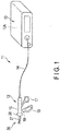
- a medical device 11 includes a handpiece 12, a power unit 13, and a cable 14 connecting the handpiece 12 and the power unit 13.
- the handpiece 12 includes: a case 15 forming an outer envelope; a fixed handle 16 formed integrally with the case 15; a handle 17 rotatable with respect to the case 15; and an operation button 18 provided on the case 15.
- the number of operation buttons 18 is one in this embodiment, a plurality of operation buttons 18 may be provided.
- the handpiece 12 includes: an energy output member 21 configured to output energy for treating biological tissue; a heat insulator 22 fixed to a back side of the energy output member 21; a support member 23 configured to support the energy output member 21 and the heat insulator 22; a heat-insulation cover 25 configured to cover a below-mentioned housing 24 of the support member 23; a heat conductor 26 provided to extend over the heat insulator 22 and the support member 23; a rotatable knob 28 fixed to a below-mentioned sheath 27 of the support member 23; a jaw 31 attached to the sheath 27 to be rotatable with respect to the energy output member 21; a pad 29 provided on the jaw 31; a cylindrical movable pipe 32 placed inside the sheath 27 and configured to move forward or backward when the jaw 31 is opened or closed; a wiring section 34 configured to electrically connect the below-mentioned heater 33 of the energy output member 21 to the power unit 13; and a covering section 35 configured
- one of the two directions parallel to the central axis direction (longitudinal direction) C of the sheath 27 is referred to as the distal direction C1, and the direction opposite to the distal direction as the proximal direction C2.
- the energy output member 21 (first grasping piece 21) and the jaw 31 (second grasping piece 31) constitute an end effector 36 for treating the site of the treatment object.
- the support member 23 includes the sheath 27 made of a metal and shaped like a cylindrical pipe, and the housing 24 fixed to the distal side of the sheath 27 by means of a screw, welding, etc.
- the housing 24 includes a projection section 24A configured to project from the housing 24.
- the heat conductor 26, the heat insulator 22, and the energy output member 21 can be fixed to the projection section 24A.
- the housing 24 (including the projection section 24A) is adjacent to the heat insulator 22.
- the outer periphery of the housing 24 is covered with the heat-insulation cover 25.
- the cover 25 is made of a synthetic resin material such as polyether ether ketone (PEEK).
- the cover 25 may be made of polytetrafluoroethylene (PTFE), tetrafluoroetylene-perfluoroalkylvinylether copolymer (PFA), polyimide (PI), polybenzimidazole (PBI), or the like, or made of ceramic.
- PTFE polytetrafluoroethylene
- PFA tetrafluoroetylene-perfluoroalkylvinylether copolymer
- PI polyimide
- PBI polybenzimidazole
- energy output member 21 includes a contact section 37 (blade) configured to have an angular cross-section; and the heater 33 (heater element) housed inside the contact section 37.
- the surface of the contact section 37 can include a coating, such as a fluororesin or the like, to limit biological tissue L (as shown in FIG. 4 ) from sticking to the contact section 37.
- the heater 33 is located between the contact section 37 and the heat insulator 22, and can impart heat energy to the contact section 37.
- the heater 33 is composed of resistors using stainless steel, a nickel-chromium alloy (nichrome wire), or the like.
- the contact section 37 is made of a metal having good heat conductivity, such as a copper alloy or an aluminum alloy.
- the heat insulator 22 is shown as a trapezoidal shape, but in other embodiments can be any other suitable shape such as square, triangular, etc.
- the heat insulator 22 supports the energy output member 21 on its top surface.
- the heat insulator 22 is fixed to the housing 24 in FIG. 4 , but in other embodiments, the heat insulator 22 can be fixed to other portions of the housing 24(the support member 23).
- the heat insulator 22 includes an outer edge section 38 (step section), which has a fixed width dimension along the outer periphery of the energy output member 21.
- the outer edge section 38 projects more outward than the outer periphery of the energy output member 21.
- the medical device 11 according to this embodiment therefore has lower risk of erroneously bringing the energy output member 21 into contact with biological tissue around the site of the treatment object.
- the heat insulator 22 is made of a synthetic resin material.
- the heat insulator 22 is made of PEEK or the like.
- the material of the heat insulator 22 is, however, not limited to such.
- the heat insulator 22 may be made of a synthetic resin material other than PEEK, such as PTFE, PFA, PI, or PBI, or made of ceramic with low heat conductivity, etc.
- the heat insulator 22 has sufficiently lower heat conductivity than metal, etc., and so exhibits heat insulation property to insulate heat of the energy output member 21 transferring to the housing 24.
- the heat conductor 26 is housed in a depression formed in the housing 24.
- the heat conductor 26 is located between the heat insulator 22 and the housing 24.
- the heat conductor 26 includes a body section 41 (heat conduction section) and a heatsink section 42 at the end of the body section 41.
- the heatsink section 42 is formed as a pair of blocks or masses configured to extend in the direction (vertical direction) intersecting the treatment surface of the contact section 37.
- the heat conductor 26 is made of a metal containing material having good heat conductivity, such as copper or aluminum.
- the total volume of the two parts of the heatsink section 42 can be equal to or larger than the volume of the body section 41. Moreover, the total cross-sectional area of the two parts of the heatsink section 42 along a plane intersecting the direction in which the body section 41 extends can be larger than the cross-sectional area of the body section 41 along a plane parallel to the plane.
- the housing 24 forms the outer envelope of the end effector 36, and supports the energy output member 21 with the heat insulator 22 in between.
- the housing 24 is made of a suitable metal containing material such as stainless steel. The housing 24 therefore has lower heat conductivity than the heat conductor 26.
- the housing 24 includes an engaging section 43 whose shape is complementary to the shape of the heatsink section 42 of the heat conductor 26.
- the engaging section 43 includes: a rib section 43A sandwiched between the pair of blocks of the heatsink section 42; and a wall section 43B configured to hold the periphery of the blocks.
- the housing 24 is thermally connected to the heatsink section 42, to receive heat transferred to the heatsink section 42 and conduct the heat toward the sheath 27.
- the sheath 27 is shaped like a rod, and supports the housing 24 on the distal side. As illustrated in FIG. 1 , the sheath 27 is attached to the case 15 rotatably with respect to the case 15, at its proximal part.
- the rotatable knob 28 is fixed to the sheath 27. By rotating the rotatable knob 28 with respect to the case 15, the sheath 27, the energy output member 21, and the jaw 31 can be rotated integrally about the central axis C.
- the sheath 27 has a support pin 45 for supporting the jaw 31 in its distal part.
- the jaw 31 is rotatable about the support pin 45 between a separate position where the jaw 31 is separate from the energy output member 21 as illustrated in FIG. 2 and a contact position where the jaw 31 is in contact with the energy output member 21.
- the jaw 31 is provided with the same cover 25 as the energy output member 21 (the first grasping piece 21).
- the jaw 31 is configured to be opened and closed to release or squeeze the biological tissue L between the energy output member 21 and the jaw 31. (see FIG. 3 ).
- the operator can open and close the jaw 31 by rotating the handle 17 with respect to the case 15.
- the movable pipe 32 (see FIG. 2 ) inside the sheath 27 moves forward and backward along the central axis C of the sheath 27.
- the jaw 31 is configured to pivotally connect to the sheath 27 and housing 24, which allows the jaw 31 to open and close in response to a forward and backward motion of the sheath 27.
- the wiring section 34 is configured to connect to a heater control section 13A included in the power unit 13.
- the wiring section 34 is also configured to connect to the heater 33.
- the wiring section 34 is partly located inside the cable 14.
- the wiring section 34 is composed of electric wires the surfaces of which are covered with a sheet-like insulation member.
- the covering section 35 is shaped like a duct, and formed integrally with the heat insulator 22 on the distal direction C1 side.
- the covering section 35 is made of the same material as the heat insulator 22, and has heat insulation property.
- the heat insulator 22 and the covering section 35 are formed integrally by insert molding the wiring section 34.
- the covering section 35 is in contact with the heatsink section 42 of the heat conductor 26, and is thermally connected to the heatsink section 42.
- the functions of the medical device 11 according to this embodiment are described below, with reference to FIGS. 3 , 5 , and 6 .
- the operator can sandwich the biological tissue L between the energy output member 21 and the jaw 31 by operating the handle 17.
- the operator can then feed heat energy into the sandwiched biological tissue L by operating the operation button 18 in this state.
- the operator can thus coagulate or excise the biological tissue.
- the temperature of the energy output member 21 may become high (e.g. about 200°C to about 300°C).
- the heat insulator 22 having low heat conductivity is provided between the energy output member 21 and the housing 24, so that the amount of heat transferred from the energy output member 21 to the housing 24 per unit time is reduced. Therefore, even in the case where the operator unintentionally brings the housing 24 (the back side of the energy output member 21) into contact with surrounding tissue other than the treatment site, adverse thermal effect on the surrounding tissue can be avoided.
- any heat conducted through the heat insulator 22 toward the housing 24 is conducted through the body section 41 of the heat conductor 26 to the heatsink section 42.
- the heat conducted to the heatsink section 42 is then conducted through the engaging section 43 in close contact with the heatsink section 42 to the housing 24.
- the heat conducted to the housing 24 is released toward the sheath 27.
- the housing 24 is covered with the cover 25, the possibility of adverse thermal effect on the surrounding tissue in the case where the operator unintentionally brings the housing 24 into contact with the surrounding tissue can be reduced.
- a medical device 11 includes: a support member 23; an energy output member 21 that outputs energy for treating biological tissue; a heat insulator 22 provided on a back surface of the energy output member 21, and supported on a distal side of the support member 23; and a heat conductor 26 that extends over the heat insulator 22 and a part of the support member 23 more proximal than the energy output member 21, and conducts, to the support member 23, heat transferred from the energy output member 21 to the heat insulator 22.
- the heat insulator 22 covers the back surface of the energy output member 21, and so the heat of the energy output member 21 is kept from being transferred to the back side. Even in the case where the temperature of the heat insulator 22 becomes high due to extended use, the heat of the heat insulator 22 can be conducted to the support member 23 by the heat conductor 26. This suppresses the accumulation of heat in the heat insulator 22. Therefore, even in the case where the operator unintentionally brings the back side of the energy output member 21 into contact with surrounding tissue, adverse thermal effect on the surrounding tissue (heat invasion to the surrounding tissue) can be avoided.
- the heat conductor 26 includes a heatsink section 42 at an end opposite to an end adjacent to the heat insulator 22. With this structure, the heat conductor 26 includes the heatsink section 42, so that the heat received from the heat insulator 22 can be actively guided to the heatsink section 42. This reduces the amount of heat accumulated in the heat insulator 22, and reduces heat invasion to the surrounding tissue.
- the heat conductor 26 is thermally connected to the support member 23 through the heatsink section 42. With this structure, the heat guided to the heatsink section 42 is released toward the support member 23. This facilitates the cooling of the heatsink section 42, and lowers the temperature of the heatsink section 42. The flow of heat from the heat insulator 22 through the heat conductor 26 to the support member 23 can thus be formed. Accordingly, the heat conducted to the heatsink section 42 is kept from flowing back toward the heat insulator 22, so that the temperature around the heat insulator 22 can be further lowered.
- the heat conductor 26 can include a body section 41 configured to connect the end adjacent to the heat insulator 22 and the heatsink section 42, and the heatsink section 42 has a larger volume than the body section 41.
- the heat conductor 26 can include a body section 41 configured to connect the end adjacent to the heat insulator 22 and the heatsink section 42, and a cross-sectional area of the heatsink section 42 along a plane intersecting a direction in which the body section 41 extends is larger than a cross-sectional area of the body section 41 along a plane parallel to the plane.
- the medical device 11 includes a housing 24 adjacent to the heat insulator 22, and the heat conductor 26 has higher heat conductivity than the housing 24.
- the heat conductor 26 has higher heat conductivity than the housing 24, so that the heat transferred to the heat insulator 22 can be efficiently conducted to the support member 23 to cool the heat insulator 22 and the housing-24.
- the medical device 11 includes a heat-insulation cover 25 configured to cover an outer periphery of the housing 24.
- the energy output member 21 includes: a contact section 37 that comes into contact with a treatment object; and a heater 33 that is located between the contact section 37 and the heat insulator 22, and heats the contact section 37.
- a contact section 37 that comes into contact with a treatment object
- a heater 33 that is located between the contact section 37 and the heat insulator 22, and heats the contact section 37.
- the medical device 11 includes: a wiring section 34 connected to the heater 33; and a covering section 35 covering the wiring section 34 and formed integrally with the heat insulator 22.
- a wiring section 34 connected to the heater 33
- a covering section 35 covering the wiring section 34 and formed integrally with the heat insulator 22.
- the covering section 35 is thermally connected to the heatsink section 42. With this structure, the heat of the wiring section 34 and covering section 35 is released to the heatsink section 42. As a result, malfunctions such as a fracture of the wiring section 34 caused by a temperature increase can be avoided.
- the heat insulator 22 has a pair of hollow parts 46 configured to extend in the central axis direction C of the sheath 27.
- the heat insulator 22 has a pair of grooves in the surface in contact with the housing 24, which extend in the central axis direction C of the sheath 27.
- a gas such as air, a mixture of gases, a liquid, a mixture of liquids, or a mixture of one or more gases and one or more liquids is present inside the hollow parts 46. Since the hollow parts 46 in this modification enhance the heat insulation property of the end effector 36, the heat conductivity of the heat insulator 22 is further reduced.
- the heat insulator 22 has a hollow part 46 filled with the gas.
- the heat conductivity of the heat insulator 22 is further reduced, which prevents the heat of the energy output member 21 from being directly transferred to the heat conductor 26 and the housing 24.
- the heat conductor 26 releases the heat of the heat insulator 22 to the support member 23. Therefore, even in the case where the operator unintentionally brings the back side of the energy output member 21 into contact with surrounding tissue other than the treatment site, adverse thermal effect on the surrounding tissue can be avoided.
- a second modification of the medical device 11 is described below, with reference to FIG. 8 .
- the shape of the heatsink section 42 of the heat conductor 26 is different.
- the heatsink section 42 is formed as a pair of blocks configured to extend in the direction (horizontal direction) along the treatment surface of the contact section 37.
- the total volume of the two parts of the heatsink section 42 can be larger than the volume of the body section 41 of the heat conductor 26.
- the cross-sectional area of the heatsink section 42 along a plane intersecting the direction in which the body section 41 extends can be larger than the cross-sectional area of the body section 41 along a plane parallel to the plane.
- the housing 24 includes an engaging section 43 whose shape is complementary to the shape of the heatsink section 42 of the heat conductor 26.
- the engaging section 43 includes: a rib section 43A sandwiched between the pair of blocks of the heatsink section 42; and a wall section 43B configured to hold the periphery of the blocks. According to this modification, even in the case where the shape of the heatsink section 42 is different, the heat of the heat insulator 22 can be actively guided to the heatsink section 42. This further reduces the thermal effect on the surrounding tissue other than the treatment site.
- a third modification of the medical device 11 is described below, with reference to FIG. 9 .
- the shape of the heatsink section 42 of the heat conductor 26 is different.
- the heatsink section 42 is shaped like a block having lattice-like slits 47.
- the volume of the heatsink section 42 is larger than the volume of the body section 41 of the heat conductor 26. Moreover, the cross-sectional area of the heatsink section 42 along a plane intersecting the direction in which the body section 41 extends can be larger than the cross-sectional area of the body section 41 along a plane parallel to the plane.
- the housing 24 includes an engaging section 43 whose shape is complementary to the shape of the heatsink section 42 of the heat conductor 26.
- the engaging section 43 includes: a rib section 43A having a lattice-frame shape to be inserted into a slit 47 of the heatsink section 42; and a wall section 43B configured to hold the periphery of the heatsink section 42.
- the housing 24 is thermally connected to the heatsink section 42, to receive heat transferred to the heatsink section 42 and to conduct the heat toward the sheath 27.
- the heat of the heat insulator 22 can be actively guided to the heatsink section 42. This further reduces the thermal effect on the surrounding tissue other than the treatment site.
- the housing 24 of the support member 23 is made of a metal containing material having good heat conductivity.
- the housing 24 is made of a high heat conductive material such as an aluminum alloy.
- the material of the housing 24 is, however, not limited to such, and may be any material having good heat conductivity.
- the housing 24 may be made of a copper alloy or the like.
- the housing 24 includes a plurality of fins 48 for heat dissipation (radiation fins).
- heat transferred to the heat insulator 22 is conducted through the housing 24 toward the sheath 27 at any time.
- the heat is also released to the outside by the fins 48 formed in the housing 24.
- the temperature of the housing 24 is kept from becoming high, so that heat invasion to surrounding tissue other than the treatment site can be reduced.
- the present invention is not limited to the foregoing embodiments, which may be modified as appropriate without departing from the scope of the present invention.
- the energy output member 21 may be provided on the second grasping piece 31 side.
- a vibration generator (a piezoelectric element) that generates ultrasonic vibration may be provided in the handpiece 12, and a treatment portion that receives energy from the vibration generator to ultrasonically vibrate may be provided to one of the first grasping piece 21 or the second grasping piece 31. If the treatment portion that ultrasonically vibrates is provided to the end effector 36, biological tissue L can be excised or coagulated by heat energy due to friction generated by ultrasonically vibration or kinetic energy, etc.
- the end effector 36 of the medical device 11 of the embodiments or the end effector 36 having the treatment portion that ultrasonically vibrates may be configured to allow a high-frequency current to flow between the first grasping piece 21 and the second grasping piece 31.
- a plus electrode to output the high-frequency current is provided to one of the first grasping piece 21 or the second grasping piece 31, and a minus electrode is provided to another one of the first grasping piece 21 or the second grasping piece 31.
- the medical device 11 can perform blood coagulation and coagulation relative to the biological tissue L by the high-frequency current.
- one medical device 11 can of course be configured by properly combining the medical devices 11 described in the aforementioned embodiments, modifications, and variations.
Landscapes
- Health & Medical Sciences (AREA)
- Surgery (AREA)
- Engineering & Computer Science (AREA)
- Life Sciences & Earth Sciences (AREA)
- Biomedical Technology (AREA)
- Otolaryngology (AREA)
- Nuclear Medicine, Radiotherapy & Molecular Imaging (AREA)
- Plasma & Fusion (AREA)
- Physics & Mathematics (AREA)
- Heart & Thoracic Surgery (AREA)
- Medical Informatics (AREA)
- Molecular Biology (AREA)
- Animal Behavior & Ethology (AREA)
- General Health & Medical Sciences (AREA)
- Public Health (AREA)
- Veterinary Medicine (AREA)
- Surgical Instruments (AREA)
Abstract
Description
- The present invention relates to a medical device for treating biological tissue using energy such as heat.
- Surgical devices for cutting and sealing a blood vessel can include a jaw for sandwiching and fastening tissue, sealing the tissue by heat or the like. In other surgical devices a pair of jaws are included, each of which include a heating element. When grasped, the jaws generate heat from each element to perform an operation, such as a coagulation of the biological tissue or incising the biological tissue.
- There has been demand for more minimally invasive medical devices, to reduce the burden on patients.
- To achieve the object stated above, a medical device includes: a support member; an energy output member configured to output energy to treat biological tissue; a heat insulator provided on a back side of the energy output member, and supported at a distal end side of the support member; and a heat conductor provided to extend over the heat insulator and a portion of the support member closer to a proximal end side than the energy output member, and configured to conduct to the support member heat conducted to the heat insulator from the energy output member.
- With the structure described above, a more minimally invasive medical device can be provided.
-
-
FIG. 1 is a schematic view illustrating the overall structure of a medical device according to an embodiment. -
FIG. 2 is a side view illustrating an energy output member and jaw of a handpiece in the medical device illustrated inFIG. 1 . -
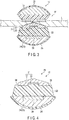
FIG. 3 is a sectional view of the handpiece along line F3-F3 inFIG. 2 . -
FIG. 4 is an enlarged sectional view illustrating the energy output member, heat insulator, and housing of the handpiece illustrated inFIG. 3 . -
FIG. 5 is an exploded perspective view illustrating the energy output member, heat conductor, and housing in the support member illustrated inFIG. 4 . -
FIG. 6 is a sectional view illustrating a heatsink section in the heat conductor, housing, and wiring section illustrated inFIG. 5 . -
FIG. 7 is a sectional view illustrating an energy output member, heat insulator, heat conductor, and housing of a medical device according to a first modification. -
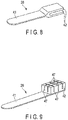
FIG. 8 is a perspective view illustrating a heat conductor of a medical device according to a second modification. -
FIG. 9 is a perspective view illustrating a heat conductor of a medical device according to a third modification. -
FIG. 10 is a sectional view illustrating an energy output member, heat insulator, and housing of a medical device according to a fourth modification. -
FIG. 11 is a sectional view along line F10-F10 inFIG. 11 . - The following describes a medical device according to an embodiment, with reference to
FIGS. 1 to 6 . - As illustrated in
FIG. 1 , amedical device 11 includes ahandpiece 12, apower unit 13, and acable 14 connecting thehandpiece 12 and thepower unit 13. - As illustrated in
FIG. 1 , thehandpiece 12 includes: acase 15 forming an outer envelope; afixed handle 16 formed integrally with thecase 15; ahandle 17 rotatable with respect to thecase 15; and anoperation button 18 provided on thecase 15. Although the number ofoperation buttons 18 is one in this embodiment, a plurality ofoperation buttons 18 may be provided. - As illustrated in
FIGS. 1 through 6 , thehandpiece 12 includes: anenergy output member 21 configured to output energy for treating biological tissue; aheat insulator 22 fixed to a back side of theenergy output member 21; asupport member 23 configured to support theenergy output member 21 and theheat insulator 22; a heat-insulation cover 25 configured to cover a below-mentionedhousing 24 of thesupport member 23; aheat conductor 26 provided to extend over theheat insulator 22 and thesupport member 23; arotatable knob 28 fixed to a below-mentionedsheath 27 of thesupport member 23; ajaw 31 attached to thesheath 27 to be rotatable with respect to theenergy output member 21; apad 29 provided on thejaw 31; a cylindricalmovable pipe 32 placed inside thesheath 27 and configured to move forward or backward when thejaw 31 is opened or closed; awiring section 34 configured to electrically connect the below-mentionedheater 33 of theenergy output member 21 to thepower unit 13; and a coveringsection 35 configured to cover thewiring section 34. - In this embodiment, one of the two directions parallel to the central axis direction (longitudinal direction) C of the
sheath 27 is referred to as the distal direction C1, and the direction opposite to the distal direction as the proximal direction C2. As illustrated inFIG. 2 , the energy output member 21 (first grasping piece 21) and the jaw 31 (second grasping piece 31) constitute anend effector 36 for treating the site of the treatment object. - As illustrated in
FIG. 2 , thesupport member 23 includes thesheath 27 made of a metal and shaped like a cylindrical pipe, and thehousing 24 fixed to the distal side of thesheath 27 by means of a screw, welding, etc. As illustrated inFIGS. 5 , thehousing 24 includes aprojection section 24A configured to project from thehousing 24. Theheat conductor 26, theheat insulator 22, and theenergy output member 21 can be fixed to theprojection section 24A. The housing 24 (including theprojection section 24A) is adjacent to theheat insulator 22. The outer periphery of thehousing 24 is covered with the heat-insulation cover 25. Thecover 25 is made of a synthetic resin material such as polyether ether ketone (PEEK). Alternatively, thecover 25 may be made of polytetrafluoroethylene (PTFE), tetrafluoroetylene-perfluoroalkylvinylether copolymer (PFA), polyimide (PI), polybenzimidazole (PBI), or the like, or made of ceramic. - As illustrated in
FIG. 4 and5 ,energy output member 21 includes a contact section 37 (blade) configured to have an angular cross-section; and the heater 33 (heater element) housed inside thecontact section 37. The surface of thecontact section 37 can include a coating, such as a fluororesin or the like, to limit biological tissue L (as shown inFIG. 4 ) from sticking to thecontact section 37. Theheater 33 is located between thecontact section 37 and theheat insulator 22, and can impart heat energy to thecontact section 37. For example, theheater 33 is composed of resistors using stainless steel, a nickel-chromium alloy (nichrome wire), or the like. Thecontact section 37 is made of a metal having good heat conductivity, such as a copper alloy or an aluminum alloy. - As illustrated in
FIG. 4 and5 , theheat insulator 22 is shown as a trapezoidal shape, but in other embodiments can be any other suitable shape such as square, triangular, etc. Theheat insulator 22 supports theenergy output member 21 on its top surface. Theheat insulator 22 is fixed to thehousing 24 inFIG. 4 , but in other embodiments, theheat insulator 22 can be fixed to other portions of the housing 24(the support member 23). Theheat insulator 22 includes an outer edge section 38 (step section), which has a fixed width dimension along the outer periphery of theenergy output member 21. Theouter edge section 38 projects more outward than the outer periphery of theenergy output member 21. Themedical device 11 according to this embodiment therefore has lower risk of erroneously bringing theenergy output member 21 into contact with biological tissue around the site of the treatment object. - For example, the
heat insulator 22 is made of a synthetic resin material. In more detail, theheat insulator 22 is made of PEEK or the like. The material of theheat insulator 22 is, however, not limited to such. Theheat insulator 22 may be made of a synthetic resin material other than PEEK, such as PTFE, PFA, PI, or PBI, or made of ceramic with low heat conductivity, etc. Theheat insulator 22 has sufficiently lower heat conductivity than metal, etc., and so exhibits heat insulation property to insulate heat of theenergy output member 21 transferring to thehousing 24. - As illustrated in
FIG. 4 , theheat conductor 26 is housed in a depression formed in thehousing 24. Theheat conductor 26 is located between theheat insulator 22 and thehousing 24. As illustrated inFIG. 5 , theheat conductor 26 includes a body section 41 (heat conduction section) and aheatsink section 42 at the end of thebody section 41. Theheatsink section 42 is formed as a pair of blocks or masses configured to extend in the direction (vertical direction) intersecting the treatment surface of thecontact section 37. Theheat conductor 26 is made of a metal containing material having good heat conductivity, such as copper or aluminum. - The total volume of the two parts of the
heatsink section 42 can be equal to or larger than the volume of thebody section 41. Moreover, the total cross-sectional area of the two parts of theheatsink section 42 along a plane intersecting the direction in which thebody section 41 extends can be larger than the cross-sectional area of thebody section 41 along a plane parallel to the plane. - The
housing 24 forms the outer envelope of theend effector 36, and supports theenergy output member 21 with theheat insulator 22 in between. Thehousing 24 is made of a suitable metal containing material such as stainless steel. Thehousing 24 therefore has lower heat conductivity than theheat conductor 26. - As illustrated in
FIG. 5 , thehousing 24 includes an engagingsection 43 whose shape is complementary to the shape of theheatsink section 42 of theheat conductor 26. In detail, the engagingsection 43 includes: arib section 43A sandwiched between the pair of blocks of theheatsink section 42; and awall section 43B configured to hold the periphery of the blocks. Thus, thehousing 24 is thermally connected to theheatsink section 42, to receive heat transferred to theheatsink section 42 and conduct the heat toward thesheath 27. - The
sheath 27 is shaped like a rod, and supports thehousing 24 on the distal side. As illustrated inFIG. 1 , thesheath 27 is attached to thecase 15 rotatably with respect to thecase 15, at its proximal part. Therotatable knob 28 is fixed to thesheath 27. By rotating therotatable knob 28 with respect to thecase 15, thesheath 27, theenergy output member 21, and thejaw 31 can be rotated integrally about the central axis C. Thesheath 27 has asupport pin 45 for supporting thejaw 31 in its distal part. - The
jaw 31 is rotatable about thesupport pin 45 between a separate position where thejaw 31 is separate from theenergy output member 21 as illustrated inFIG. 2 and a contact position where thejaw 31 is in contact with theenergy output member 21. Thejaw 31 is provided with thesame cover 25 as the energy output member 21 (the first grasping piece 21). Thejaw 31 is configured to be opened and closed to release or squeeze the biological tissue L between theenergy output member 21 and thejaw 31. (seeFIG. 3 ). - The operator can open and close the
jaw 31 by rotating thehandle 17 with respect to thecase 15. In detail, when the operator operates thehandle 17, the movable pipe 32 (seeFIG. 2 ) inside thesheath 27 moves forward and backward along the central axis C of thesheath 27. Thejaw 31 is configured to pivotally connect to thesheath 27 andhousing 24, which allows thejaw 31 to open and close in response to a forward and backward motion of thesheath 27. - As illustrated in
FIG. 5 , thewiring section 34 is configured to connect to aheater control section 13A included in thepower unit 13. Thewiring section 34 is also configured to connect to theheater 33. Thewiring section 34 is partly located inside thecable 14. As illustrated inFIG. 6 , thewiring section 34 is composed of electric wires the surfaces of which are covered with a sheet-like insulation member. The coveringsection 35 is shaped like a duct, and formed integrally with theheat insulator 22 on the distal direction C1 side. Thus, the coveringsection 35 is made of the same material as theheat insulator 22, and has heat insulation property. Theheat insulator 22 and thecovering section 35 are formed integrally by insert molding thewiring section 34. The coveringsection 35 is in contact with theheatsink section 42 of theheat conductor 26, and is thermally connected to theheatsink section 42. - The functions of the
medical device 11 according to this embodiment are described below, with reference toFIGS. 3 ,5 , and6 . - In the treatment, the operator can sandwich the biological tissue L between the
energy output member 21 and thejaw 31 by operating thehandle 17. The operator can then feed heat energy into the sandwiched biological tissue L by operating theoperation button 18 in this state. The operator can thus coagulate or excise the biological tissue. - When the coagulation and incision treatment or the coagulation treatment is performed on the biological tissue (treatment object), the temperature of the
energy output member 21 may become high (e.g. about 200°C to about 300°C). In this embodiment, theheat insulator 22 having low heat conductivity is provided between theenergy output member 21 and thehousing 24, so that the amount of heat transferred from theenergy output member 21 to thehousing 24 per unit time is reduced. Therefore, even in the case where the operator unintentionally brings the housing 24 (the back side of the energy output member 21) into contact with surrounding tissue other than the treatment site, adverse thermal effect on the surrounding tissue can be avoided. - Any heat conducted through the
heat insulator 22 toward thehousing 24 is conducted through thebody section 41 of theheat conductor 26 to theheatsink section 42. The heat conducted to theheatsink section 42 is then conducted through the engagingsection 43 in close contact with theheatsink section 42 to thehousing 24. The heat conducted to thehousing 24 is released toward thesheath 27. Moreover, since thehousing 24 is covered with thecover 25, the possibility of adverse thermal effect on the surrounding tissue in the case where the operator unintentionally brings thehousing 24 into contact with the surrounding tissue can be reduced. - According to this embodiment, a
medical device 11 includes: asupport member 23; anenergy output member 21 that outputs energy for treating biological tissue; aheat insulator 22 provided on a back surface of theenergy output member 21, and supported on a distal side of thesupport member 23; and aheat conductor 26 that extends over theheat insulator 22 and a part of thesupport member 23 more proximal than theenergy output member 21, and conducts, to thesupport member 23, heat transferred from theenergy output member 21 to theheat insulator 22. - With this structure, the
heat insulator 22 covers the back surface of theenergy output member 21, and so the heat of theenergy output member 21 is kept from being transferred to the back side. Even in the case where the temperature of theheat insulator 22 becomes high due to extended use, the heat of theheat insulator 22 can be conducted to thesupport member 23 by theheat conductor 26. This suppresses the accumulation of heat in theheat insulator 22. Therefore, even in the case where the operator unintentionally brings the back side of theenergy output member 21 into contact with surrounding tissue, adverse thermal effect on the surrounding tissue (heat invasion to the surrounding tissue) can be avoided. - The
heat conductor 26 includes aheatsink section 42 at an end opposite to an end adjacent to theheat insulator 22. With this structure, theheat conductor 26 includes theheatsink section 42, so that the heat received from theheat insulator 22 can be actively guided to theheatsink section 42. This reduces the amount of heat accumulated in theheat insulator 22, and reduces heat invasion to the surrounding tissue. - The
heat conductor 26 is thermally connected to thesupport member 23 through theheatsink section 42. With this structure, the heat guided to theheatsink section 42 is released toward thesupport member 23. This facilitates the cooling of theheatsink section 42, and lowers the temperature of theheatsink section 42. The flow of heat from theheat insulator 22 through theheat conductor 26 to thesupport member 23 can thus be formed. Accordingly, the heat conducted to theheatsink section 42 is kept from flowing back toward theheat insulator 22, so that the temperature around theheat insulator 22 can be further lowered. - The
heat conductor 26 can include abody section 41 configured to connect the end adjacent to theheat insulator 22 and theheatsink section 42, and theheatsink section 42 has a larger volume than thebody section 41. Theheat conductor 26 can include abody section 41 configured to connect the end adjacent to theheat insulator 22 and theheatsink section 42, and a cross-sectional area of theheatsink section 42 along a plane intersecting a direction in which thebody section 41 extends is larger than a cross-sectional area of thebody section 41 along a plane parallel to the plane. With these structures, the heat capacity on theheatsink section 42 side is increased, and therefore the heat received from theheat insulator 22 can be actively guided to theheatsink section 42. By reducing the amount of heat accumulated in theheat insulator 22 in this way, themedical device 11 with low heat invasiveness to surrounding tissue can be realized. - The
medical device 11 includes ahousing 24 adjacent to theheat insulator 22, and theheat conductor 26 has higher heat conductivity than thehousing 24. With this structure, theheat conductor 26 has higher heat conductivity than thehousing 24, so that the heat transferred to theheat insulator 22 can be efficiently conducted to thesupport member 23 to cool theheat insulator 22 and the housing-24. - The
medical device 11 includes a heat-insulation cover 25 configured to cover an outer periphery of thehousing 24. With this structure, the risk of adverse thermal effect on surrounding tissue around the treatment site in the case where the operator unintentionally brings thehousing 24 into contact with the surrounding tissue can be reduced. - The
energy output member 21 includes: acontact section 37 that comes into contact with a treatment object; and aheater 33 that is located between thecontact section 37 and theheat insulator 22, and heats thecontact section 37. With this structure, heat generated from theheater 33 can be mainly conducted to thecontact section 37, while preventing the conduction of heat to theheat insulator 22. This enables heating of thecontact section 37 and suppresses heat loss. - The
medical device 11 includes: awiring section 34 connected to theheater 33; and acovering section 35 covering thewiring section 34 and formed integrally with theheat insulator 22. With this structure, thewiring section 34 that becomes high in temperature together with theheater 33 is covered with the coveringsection 35, and so the heat of thewiring section 34 can be kept from diffusing to the surroundings. - The covering
section 35 is thermally connected to theheatsink section 42. With this structure, the heat of thewiring section 34 andcovering section 35 is released to theheatsink section 42. As a result, malfunctions such as a fracture of thewiring section 34 caused by a temperature increase can be avoided. - Modifications of the
medical device 11 are described below. The following mainly describes the differences from the foregoing embodiment, and the illustration or description of the same parts as in the foregoing embodiment is omitted. - A first modification of the
medical device 11 is described below, with reference toFIG. 7 . Theheat insulator 22 has a pair ofhollow parts 46 configured to extend in the central axis direction C of thesheath 27. In other words, theheat insulator 22 has a pair of grooves in the surface in contact with thehousing 24, which extend in the central axis direction C of thesheath 27. A gas, such as air, a mixture of gases, a liquid, a mixture of liquids, or a mixture of one or more gases and one or more liquids is present inside thehollow parts 46. Since thehollow parts 46 in this modification enhance the heat insulation property of theend effector 36, the heat conductivity of theheat insulator 22 is further reduced. - According to the first modification, the
heat insulator 22 has ahollow part 46 filled with the gas. With this structure, the heat conductivity of theheat insulator 22 is further reduced, which prevents the heat of theenergy output member 21 from being directly transferred to theheat conductor 26 and thehousing 24. Moreover, even in the case of using themedical device 11 under relatively harsh conditions such as long continuous use, theheat conductor 26 releases the heat of theheat insulator 22 to thesupport member 23. Therefore, even in the case where the operator unintentionally brings the back side of theenergy output member 21 into contact with surrounding tissue other than the treatment site, adverse thermal effect on the surrounding tissue can be avoided. - A second modification of the
medical device 11 is described below, with reference toFIG. 8 . In this modification, the shape of theheatsink section 42 of theheat conductor 26 is different. Theheatsink section 42 is formed as a pair of blocks configured to extend in the direction (horizontal direction) along the treatment surface of thecontact section 37. - The total volume of the two parts of the
heatsink section 42 can be larger than the volume of thebody section 41 of theheat conductor 26. Moreover, the cross-sectional area of theheatsink section 42 along a plane intersecting the direction in which thebody section 41 extends can be larger than the cross-sectional area of thebody section 41 along a plane parallel to the plane. - The
housing 24 includes an engagingsection 43 whose shape is complementary to the shape of theheatsink section 42 of theheat conductor 26. In detail, the engagingsection 43 includes: arib section 43A sandwiched between the pair of blocks of theheatsink section 42; and awall section 43B configured to hold the periphery of the blocks. According to this modification, even in the case where the shape of theheatsink section 42 is different, the heat of theheat insulator 22 can be actively guided to theheatsink section 42. This further reduces the thermal effect on the surrounding tissue other than the treatment site. - A third modification of the
medical device 11 is described below, with reference toFIG. 9 . In this modification, the shape of theheatsink section 42 of theheat conductor 26 is different. Theheatsink section 42 is shaped like a block having lattice-like slits 47. - The volume of the
heatsink section 42 is larger than the volume of thebody section 41 of theheat conductor 26. Moreover, the cross-sectional area of theheatsink section 42 along a plane intersecting the direction in which thebody section 41 extends can be larger than the cross-sectional area of thebody section 41 along a plane parallel to the plane. - The
housing 24 includes an engagingsection 43 whose shape is complementary to the shape of theheatsink section 42 of theheat conductor 26. In detail, the engagingsection 43 includes: arib section 43A having a lattice-frame shape to be inserted into aslit 47 of theheatsink section 42; and awall section 43B configured to hold the periphery of theheatsink section 42. Thus, thehousing 24 is thermally connected to theheatsink section 42, to receive heat transferred to theheatsink section 42 and to conduct the heat toward thesheath 27. - According to this modification, even in the case where the shape of the
heatsink section 42 is different, the heat of theheat insulator 22 can be actively guided to theheatsink section 42. This further reduces the thermal effect on the surrounding tissue other than the treatment site. - A fourth modification of the medical device is described below, with reference to
FIGS. 10 and 11 . In this modification, thehousing 24 of thesupport member 23 is made of a metal containing material having good heat conductivity. In more detail, thehousing 24 is made of a high heat conductive material such as an aluminum alloy. The material of thehousing 24 is, however, not limited to such, and may be any material having good heat conductivity. For example, thehousing 24 may be made of a copper alloy or the like. - As illustrated in
FIG. 11 , the outer peripheral surface of thehousing 24 is covered with the heat-insulation cover 25. Thehousing 24 includes a plurality offins 48 for heat dissipation (radiation fins). - In this modification, heat transferred to the
heat insulator 22 is conducted through thehousing 24 toward thesheath 27 at any time. The heat is also released to the outside by thefins 48 formed in thehousing 24. Hence, the temperature of thehousing 24 is kept from becoming high, so that heat invasion to surrounding tissue other than the treatment site can be reduced. - The present invention is not limited to the foregoing embodiments, which may be modified as appropriate without departing from the scope of the present invention. Although the foregoing embodiment describes the case where the
energy output member 21 is provided on the first graspingpiece 21 side of theend effector 36, theenergy output member 21 may be provided on the secondgrasping piece 31 side. In addition, a vibration generator (a piezoelectric element) that generates ultrasonic vibration may be provided in thehandpiece 12, and a treatment portion that receives energy from the vibration generator to ultrasonically vibrate may be provided to one of the first graspingpiece 21 or the secondgrasping piece 31. If the treatment portion that ultrasonically vibrates is provided to theend effector 36, biological tissue L can be excised or coagulated by heat energy due to friction generated by ultrasonically vibration or kinetic energy, etc. - Furthermore, the
end effector 36 of themedical device 11 of the embodiments or theend effector 36 having the treatment portion that ultrasonically vibrates may be configured to allow a high-frequency current to flow between the first graspingpiece 21 and the secondgrasping piece 31. In this case, a plus electrode to output the high-frequency current is provided to one of the first graspingpiece 21 or the secondgrasping piece 31, and a minus electrode is provided to another one of the first graspingpiece 21 or the secondgrasping piece 31. In the structure where high frequency energy can be introduced to the biological tissue L, in addition to heat energy or ultrasonic energy, themedical device 11 can perform blood coagulation and coagulation relative to the biological tissue L by the high-frequency current. In addition, onemedical device 11 can of course be configured by properly combining themedical devices 11 described in the aforementioned embodiments, modifications, and variations. - The described embodiments and examples of the present disclosure are intended to be illustrative rather than restrictive, and are not intended to represent every embodiment or example of the present disclosure. While the fundamental novel features of the disclosure as applied to various specific embodiments thereof have been shown, described and pointed out, it will also be understood that various omissions, substitutions and changes in the form and details of the devices illustrated and in their operation, may be made by those skilled in the art without departing from the spirit of the disclosure. For example, it is expressly intended that all combinations of those elements and/or method steps which perform substantially the same function in substantially the same way to achieve the same results are within the scope of the disclosure. Moreover, it should be recognized that structures and/or elements and/or method steps shown and/or described in connection with any disclosed form or embodiment of the disclosure may be incorporated in any other disclosed or described or suggested form or embodiment as a general matter of design choice. Further, various modifications and variations can be made without departing from the spirit or scope of the disclosure as set forth in the following claims both literally and in equivalents recognized in law.
-
- 11
- medical device
- 21
- energy output member
- 22
- heat insulator
- 23
- support member
- 24
- housing
- 25
- cover
- 26
- heat conductor
- 33
- heater
- 34
- wiring section
- 35
- covering section
- 37
- contact section
- 38
- outer edge section
- 41
- body section
- 42
- heatsink section
- 46
- hollow part
- 48
- fin
Claims (13)
- A medical device comprising:a support member;an energy output member configured to output energy to treat biological tissue;a heat insulator provided on a back side of the energy output member, and supported at a distal end side of the support member; anda heat conductor provided to extend over the heat insulator and a portion of the support member closer to a proximal end side than the energy output member, and configured to conduct to the support member heat conducted to the heat insulator from the energy output member.
- The medical device according to claim 1, wherein the heat conductor comprises a heatsink section, the heatsink section being provided to an end of the heat conductor opposite to an end adjacent to the heat insulator.
- The medical device according to claim 2, wherein the heat conductor is thermally connected to the support member via the heatsink section.
- The medical device according to claim 3, wherein the heat conductor comprises a body section that connects the end adjacent to the heat insulator to the heatsink section, and
the heatsink section has a volume greater than the body section. - The medical device according to claim 3, wherein the heat conductor comprises a body section that connects the end adjacent to the heat insulator to the heatsink section, and
wherein a cross-sectional area of the heatsink section along a plane intersecting a direction in which the body section extends is larger than a cross-sectional area of the body section along a plane parallel to the intersecting plane. - The medical device according to claim 1, wherein the heat insulator has a hollow part filled with gas.
- The medical device according to claim 1, wherein the heat insulator includes an outer edge section provided along an outer periphery of the energy output member, and the outer edge section projects more outward than the outer periphery of the energy output member.
- The medical device according to claim 1, comprising a housing adjacent to the heat insulator,
wherein the heat conductor has greater heat conductivity than the housing. - The medical device according to claim 8, comprising a heat-insulation cover that covers an outer periphery of the housing.
- The medical device according to claim 2, wherein the energy output member comprises:a contact section that comes into contact with a treatment object; anda heater located between the contact section and the heat insulator, and configured to heat the contact section.
- The medical device according to claim 10, comprising:a wiring section connected to the heater; anda covering section covering the wiring section and formed integrally with the heat insulator.
- The medical device according to claim 11, wherein the covering section is thermally connected to the heatsink section.
- The medical device according to claim 8, wherein the housing comprises radiation fins capable of releasing heat to an external environment.
Applications Claiming Priority (2)
| Application Number | Priority Date | Filing Date | Title |
|---|---|---|---|
| JP2015177503 | 2015-09-09 | ||
| PCT/JP2016/063912 WO2017043120A1 (en) | 2015-09-09 | 2016-05-10 | Medical device |
Publications (2)
| Publication Number | Publication Date |
|---|---|
| EP3332724A1 true EP3332724A1 (en) | 2018-06-13 |
| EP3332724A4 EP3332724A4 (en) | 2019-04-10 |
Family
ID=58239511
Family Applications (1)
| Application Number | Title | Priority Date | Filing Date |
|---|---|---|---|
| EP16843986.7A Withdrawn EP3332724A4 (en) | 2015-09-09 | 2016-05-10 | Medical device |
Country Status (5)
| Country | Link |
|---|---|
| US (1) | US10617462B2 (en) |
| EP (1) | EP3332724A4 (en) |
| JP (1) | JP6250234B2 (en) |
| CN (1) | CN107920852B (en) |
| WO (1) | WO2017043120A1 (en) |
Families Citing this family (13)
| Publication number | Priority date | Publication date | Assignee | Title |
|---|---|---|---|---|
| WO2019092822A1 (en) * | 2017-11-08 | 2019-05-16 | オリンパス株式会社 | Treatment tool |
| JP6848089B2 (en) * | 2017-11-22 | 2021-03-24 | オリンパス株式会社 | Treatment tool and manufacturing method of treatment tool |
| WO2019123532A1 (en) * | 2017-12-19 | 2019-06-27 | オリンパス株式会社 | Heat treatment tool |
| WO2019150496A1 (en) * | 2018-01-31 | 2019-08-08 | オリンパス株式会社 | Method for manufacturing treatment tool, and treatment tool |
| WO2019186656A1 (en) * | 2018-03-26 | 2019-10-03 | オリンパス株式会社 | Treatment instrument |
| CN112638296B (en) * | 2018-08-31 | 2024-10-18 | 奥林巴斯株式会社 | Medical heater, treatment device, and method for manufacturing the treatment device |
| JP7044895B2 (en) * | 2018-09-11 | 2022-03-30 | オリンパス株式会社 | Medical heaters, treatment tools, and methods for manufacturing treatment tools |
| US11490953B2 (en) * | 2018-10-01 | 2022-11-08 | Covidien Lp | Electrosurgical instrument and passively cooled jaw members thereof |
| WO2020183672A1 (en) * | 2019-03-13 | 2020-09-17 | オリンパス株式会社 | Treatment instrument |
| CN114901168A (en) * | 2019-12-30 | 2022-08-12 | 西拉格国际有限公司 | Electrosurgical end effector with thermally isolated and thermally conductive portions |
| WO2021243269A1 (en) * | 2020-05-29 | 2021-12-02 | Gyrus Acmi, Inc. D/B/A Olympus Surgical Technologies America | Monolithic ceramic surgical device and method |
| JP7645375B2 (en) * | 2021-06-23 | 2025-03-13 | オリンパス株式会社 | Ultrasonic Treatment Device |
| CN115813531A (en) * | 2022-11-04 | 2023-03-21 | 杭州维纳安可医疗科技有限责任公司 | Clamp head structure, electric knife and control method thereof |
Family Cites Families (24)
| Publication number | Priority date | Publication date | Assignee | Title |
|---|---|---|---|---|
| ATE230955T1 (en) * | 1994-06-27 | 2003-02-15 | Boston Scient Ltd | TISSUE ABLATION SYSTEM |
| US6050996A (en) * | 1997-11-12 | 2000-04-18 | Sherwood Services Ag | Bipolar electrosurgical instrument with replaceable electrodes |
| US20020107517A1 (en) * | 2001-01-26 | 2002-08-08 | Witt David A. | Electrosurgical instrument for coagulation and cutting |
| US7118587B2 (en) * | 2001-04-06 | 2006-10-10 | Sherwood Services Ag | Vessel sealer and divider |
| JP3746722B2 (en) | 2002-03-26 | 2006-02-15 | オリンパス株式会社 | Medical equipment |
| US7025763B2 (en) * | 2002-03-26 | 2006-04-11 | Olympus Corporation | Medical apparatus |
| US8128624B2 (en) * | 2003-05-01 | 2012-03-06 | Covidien Ag | Electrosurgical instrument that directs energy delivery and protects adjacent tissue |
| US7150749B2 (en) * | 2003-06-13 | 2006-12-19 | Sherwood Services Ag | Vessel sealer and divider having elongated knife stroke and safety cutting mechanism |
| US7179254B2 (en) * | 2004-03-09 | 2007-02-20 | Ethicon, Inc. | High intensity ablation device |
| US8197472B2 (en) * | 2005-03-25 | 2012-06-12 | Maquet Cardiovascular, Llc | Tissue welding and cutting apparatus and method |
| JP4734058B2 (en) * | 2005-07-29 | 2011-07-27 | オリンパスメディカルシステムズ株式会社 | Medical treatment device |
| US8114104B2 (en) * | 2006-06-01 | 2012-02-14 | Ethicon Endo-Surgery, Inc. | Mechanism for assembly of ultrasonic instrument |
| US20090299353A1 (en) * | 2008-04-11 | 2009-12-03 | Lumenis Ltd. | Tissue Treatment Device and Method |
| US9314293B2 (en) * | 2008-07-16 | 2016-04-19 | Syneron Medical Ltd | RF electrode for aesthetic and body shaping devices and method of using same |
| CA2739520A1 (en) * | 2008-10-17 | 2010-04-22 | Medicold Limited | Thermotherapy application and control system |
| US8685010B2 (en) * | 2008-11-24 | 2014-04-01 | Gradiant Research, Llc | Photothermal treatment of soft tissues |
| US20110306967A1 (en) * | 2010-06-10 | 2011-12-15 | Payne Gwendolyn P | Cooling configurations for electrosurgical instruments |
| CN201949512U (en) * | 2010-12-24 | 2011-08-31 | 武汉海纳川科技有限公司 | Watch type intelligent and safety laser therapeutic apparatus |
| US8986301B2 (en) * | 2012-06-13 | 2015-03-24 | Aerin Medical Inc. | Methods and devices to treat nasal airways |
| US20120330308A1 (en) * | 2011-06-22 | 2012-12-27 | Tyco Healthcare Group Lp | Forceps |
| EP2554132B1 (en) * | 2011-08-01 | 2016-03-02 | Erbe Elektromedizin GmbH | Tissue fusion instrument |
| US9011435B2 (en) * | 2012-02-24 | 2015-04-21 | Covidien Lp | Method for manufacturing vessel sealing instrument with reduced thermal spread |
| JP5866486B2 (en) * | 2013-06-07 | 2016-02-17 | オリンパス株式会社 | Grasping treatment device |
| CN105934210B (en) * | 2013-11-26 | 2019-06-11 | 伊西康内外科有限责任公司 | Features of an Ultrasonic Knife for Applying Fluid to a Surgical Instrument |
-
2016
- 2016-05-10 WO PCT/JP2016/063912 patent/WO2017043120A1/en not_active Ceased
- 2016-05-10 CN CN201680050765.3A patent/CN107920852B/en active Active
- 2016-05-10 EP EP16843986.7A patent/EP3332724A4/en not_active Withdrawn
- 2016-05-10 JP JP2017522700A patent/JP6250234B2/en active Active
- 2016-09-09 US US15/260,408 patent/US10617462B2/en active Active
Also Published As
| Publication number | Publication date |
|---|---|
| JPWO2017043120A1 (en) | 2017-09-07 |
| US10617462B2 (en) | 2020-04-14 |
| US20170065325A1 (en) | 2017-03-09 |
| JP6250234B2 (en) | 2017-12-20 |
| WO2017043120A1 (en) | 2017-03-16 |
| CN107920852A (en) | 2018-04-17 |
| CN107920852B (en) | 2021-03-30 |
| EP3332724A4 (en) | 2019-04-10 |
Similar Documents
| Publication | Publication Date | Title |
|---|---|---|
| EP3332724A1 (en) | Medical device | |
| US7025763B2 (en) | Medical apparatus | |
| US20190175258A1 (en) | Treatment tool | |
| US7306599B2 (en) | Medical instrument and medical instrument system | |
| US20170119426A1 (en) | Treatment tool | |
| US7011656B2 (en) | Thermal cautery devices with improved heating profiles | |
| JPWO2016163450A1 (en) | Medical equipment | |
| US20210128226A1 (en) | Treatment instrument and treatment system | |
| EP3287086B1 (en) | Medical device | |
| US20150327909A1 (en) | Treatment apparatus | |
| US11684411B2 (en) | Thermal control devices for electrosurgical instruments | |
| JP6274881B2 (en) | Therapeutic treatment device | |
| US20170224406A1 (en) | Grasping treatment unit | |
| US10070913B2 (en) | Grasping treatment unit, grasping treatment instrument and grasping treatment system | |
| CN107708585A (en) | Medicine equipment | |
| US20180098809A1 (en) | Medical member and medical device | |
| JP4762149B2 (en) | Shochu with improved thermal profile and inspection method for shochu | |
| US11490953B2 (en) | Electrosurgical instrument and passively cooled jaw members thereof | |
| US20050103352A1 (en) | Method of testing thermal cautery devices | |
| JP2003144451A (en) | Operation instrument | |
| CN109922749B (en) | Medical device | |
| JPWO2018037478A1 (en) | Surgical treatment tool | |
| US20190110831A1 (en) | Treatment tool | |
| JP2020044455A (en) | Thermal control devices for electrosurgical instruments | |
| CN109963520A (en) | energy treatment device |
Legal Events
| Date | Code | Title | Description |
|---|---|---|---|
| STAA | Information on the status of an ep patent application or granted ep patent |
Free format text: STATUS: THE INTERNATIONAL PUBLICATION HAS BEEN MADE |
|
| PUAI | Public reference made under article 153(3) epc to a published international application that has entered the european phase |
Free format text: ORIGINAL CODE: 0009012 |
|
| STAA | Information on the status of an ep patent application or granted ep patent |
Free format text: STATUS: REQUEST FOR EXAMINATION WAS MADE |
|
| 17P | Request for examination filed |
Effective date: 20180305 |
|
| AK | Designated contracting states |
Kind code of ref document: A1 Designated state(s): AL AT BE BG CH CY CZ DE DK EE ES FI FR GB GR HR HU IE IS IT LI LT LU LV MC MK MT NL NO PL PT RO RS SE SI SK SM TR |
|
| AX | Request for extension of the european patent |
Extension state: BA ME |
|
| DAV | Request for validation of the european patent (deleted) | ||
| DAX | Request for extension of the european patent (deleted) | ||
| A4 | Supplementary search report drawn up and despatched |
Effective date: 20190307 |
|
| RIC1 | Information provided on ipc code assigned before grant |
Ipc: A61B 18/14 20060101ALN20190301BHEP Ipc: A61B 17/32 20060101ALN20190301BHEP Ipc: A61B 18/08 20060101AFI20190301BHEP |
|
| STAA | Information on the status of an ep patent application or granted ep patent |
Free format text: STATUS: THE APPLICATION IS DEEMED TO BE WITHDRAWN |
|
| 18D | Application deemed to be withdrawn |
Effective date: 20191008 |