US20180098809A1 - Medical member and medical device - Google Patents
Medical member and medical device Download PDFInfo
- Publication number
- US20180098809A1 US20180098809A1 US15/837,219 US201715837219A US2018098809A1 US 20180098809 A1 US20180098809 A1 US 20180098809A1 US 201715837219 A US201715837219 A US 201715837219A US 2018098809 A1 US2018098809 A1 US 2018098809A1
- Authority
- US
- United States
- Prior art keywords
- conductor
- hole
- medical member
- member according
- assembly unit
- Prior art date
- Legal status (The legal status is an assumption and is not a legal conclusion. Google has not performed a legal analysis and makes no representation as to the accuracy of the status listed.)
- Granted
Links
- 239000004020 conductor Substances 0.000 claims abstract description 102
- 239000011248 coating agent Substances 0.000 claims abstract description 42
- 238000000576 coating method Methods 0.000 claims abstract description 42
- 229920005989 resin Polymers 0.000 claims description 22
- 239000011347 resin Substances 0.000 claims description 22
- 238000000465 moulding Methods 0.000 claims description 17
- 230000000994 depressogenic effect Effects 0.000 claims description 10
- 230000000149 penetrating effect Effects 0.000 claims description 6
- 230000005540 biological transmission Effects 0.000 description 30
- 229910052751 metal Inorganic materials 0.000 description 6
- 239000002184 metal Substances 0.000 description 6
- 238000009413 insulation Methods 0.000 description 5
- 230000002093 peripheral effect Effects 0.000 description 5
- 230000008901 benefit Effects 0.000 description 4
- 210000004204 blood vessel Anatomy 0.000 description 4
- 230000015271 coagulation Effects 0.000 description 4
- 238000005345 coagulation Methods 0.000 description 4
- 238000010292 electrical insulation Methods 0.000 description 4
- 229910000881 Cu alloy Inorganic materials 0.000 description 3
- 229920003002 synthetic resin Polymers 0.000 description 3
- 239000000057 synthetic resin Substances 0.000 description 3
- 229910000838 Al alloy Inorganic materials 0.000 description 2
- 238000010586 diagram Methods 0.000 description 2
- 238000004519 manufacturing process Methods 0.000 description 2
- 238000012986 modification Methods 0.000 description 2
- 230000004048 modification Effects 0.000 description 2
- 239000000523 sample Substances 0.000 description 2
- 238000007789 sealing Methods 0.000 description 2
- 239000010935 stainless steel Substances 0.000 description 2
- 229910001220 stainless steel Inorganic materials 0.000 description 2
- 239000004696 Poly ether ether ketone Substances 0.000 description 1
- 229910001069 Ti alloy Inorganic materials 0.000 description 1
- JUPQTSLXMOCDHR-UHFFFAOYSA-N benzene-1,4-diol;bis(4-fluorophenyl)methanone Chemical compound OC1=CC=C(O)C=C1.C1=CC(F)=CC=C1C(=O)C1=CC=C(F)C=C1 JUPQTSLXMOCDHR-UHFFFAOYSA-N 0.000 description 1
- 239000000560 biocompatible material Substances 0.000 description 1
- 230000006378 damage Effects 0.000 description 1
- 230000007423 decrease Effects 0.000 description 1
- 230000002950 deficient Effects 0.000 description 1
- 238000001861 endoscopic biopsy Methods 0.000 description 1
- 238000002347 injection Methods 0.000 description 1
- 239000007924 injection Substances 0.000 description 1
- 238000001746 injection moulding Methods 0.000 description 1
- 239000007769 metal material Substances 0.000 description 1
- 229920002530 polyetherether ketone Polymers 0.000 description 1
- 238000009210 therapy by ultrasound Methods 0.000 description 1
- 230000003685 thermal hair damage Effects 0.000 description 1
Images
Classifications
-
- A—HUMAN NECESSITIES
- A61—MEDICAL OR VETERINARY SCIENCE; HYGIENE
- A61B—DIAGNOSIS; SURGERY; IDENTIFICATION
- A61B18/00—Surgical instruments, devices or methods for transferring non-mechanical forms of energy to or from the body
- A61B18/04—Surgical instruments, devices or methods for transferring non-mechanical forms of energy to or from the body by heating
- A61B18/12—Surgical instruments, devices or methods for transferring non-mechanical forms of energy to or from the body by heating by passing a current through the tissue to be heated, e.g. high-frequency current
- A61B18/14—Probes or electrodes therefor
- A61B18/1442—Probes having pivoting end effectors, e.g. forceps
- A61B18/1445—Probes having pivoting end effectors, e.g. forceps at the distal end of a shaft, e.g. forceps or scissors at the end of a rigid rod
-
- A—HUMAN NECESSITIES
- A61—MEDICAL OR VETERINARY SCIENCE; HYGIENE
- A61B—DIAGNOSIS; SURGERY; IDENTIFICATION
- A61B17/00—Surgical instruments, devices or methods
- A61B17/32—Surgical cutting instruments
- A61B17/320068—Surgical cutting instruments using mechanical vibrations, e.g. ultrasonic
- A61B17/320092—Surgical cutting instruments using mechanical vibrations, e.g. ultrasonic with additional movable means for clamping or cutting tissue, e.g. with a pivoting jaw
-
- A—HUMAN NECESSITIES
- A61—MEDICAL OR VETERINARY SCIENCE; HYGIENE
- A61N—ELECTROTHERAPY; MAGNETOTHERAPY; RADIATION THERAPY; ULTRASOUND THERAPY
- A61N7/00—Ultrasound therapy
- A61N7/02—Localised ultrasound hyperthermia
-
- A—HUMAN NECESSITIES
- A61—MEDICAL OR VETERINARY SCIENCE; HYGIENE
- A61B—DIAGNOSIS; SURGERY; IDENTIFICATION
- A61B17/00—Surgical instruments, devices or methods
- A61B17/28—Surgical forceps
- A61B17/2812—Surgical forceps with a single pivotal connection
-
- A—HUMAN NECESSITIES
- A61—MEDICAL OR VETERINARY SCIENCE; HYGIENE
- A61B—DIAGNOSIS; SURGERY; IDENTIFICATION
- A61B17/00—Surgical instruments, devices or methods
- A61B17/28—Surgical forceps
- A61B17/2812—Surgical forceps with a single pivotal connection
- A61B17/282—Jaws
- A61B2017/2825—Inserts of different material in jaws
-
- A—HUMAN NECESSITIES
- A61—MEDICAL OR VETERINARY SCIENCE; HYGIENE
- A61B—DIAGNOSIS; SURGERY; IDENTIFICATION
- A61B17/00—Surgical instruments, devices or methods
- A61B17/28—Surgical forceps
- A61B17/29—Forceps for use in minimally invasive surgery
- A61B2017/2926—Details of heads or jaws
-
- A—HUMAN NECESSITIES
- A61—MEDICAL OR VETERINARY SCIENCE; HYGIENE
- A61B—DIAGNOSIS; SURGERY; IDENTIFICATION
- A61B17/00—Surgical instruments, devices or methods
- A61B17/28—Surgical forceps
- A61B17/29—Forceps for use in minimally invasive surgery
- A61B2017/2947—Pivots
-
- A—HUMAN NECESSITIES
- A61—MEDICAL OR VETERINARY SCIENCE; HYGIENE
- A61B—DIAGNOSIS; SURGERY; IDENTIFICATION
- A61B17/00—Surgical instruments, devices or methods
- A61B17/32—Surgical cutting instruments
- A61B17/320068—Surgical cutting instruments using mechanical vibrations, e.g. ultrasonic
- A61B2017/320082—Surgical cutting instruments using mechanical vibrations, e.g. ultrasonic for incising tissue
-
- A—HUMAN NECESSITIES
- A61—MEDICAL OR VETERINARY SCIENCE; HYGIENE
- A61B—DIAGNOSIS; SURGERY; IDENTIFICATION
- A61B17/00—Surgical instruments, devices or methods
- A61B17/32—Surgical cutting instruments
- A61B17/320068—Surgical cutting instruments using mechanical vibrations, e.g. ultrasonic
- A61B17/320092—Surgical cutting instruments using mechanical vibrations, e.g. ultrasonic with additional movable means for clamping or cutting tissue, e.g. with a pivoting jaw
- A61B2017/320094—Surgical cutting instruments using mechanical vibrations, e.g. ultrasonic with additional movable means for clamping or cutting tissue, e.g. with a pivoting jaw additional movable means performing clamping operation
-
- A—HUMAN NECESSITIES
- A61—MEDICAL OR VETERINARY SCIENCE; HYGIENE
- A61B—DIAGNOSIS; SURGERY; IDENTIFICATION
- A61B17/00—Surgical instruments, devices or methods
- A61B17/32—Surgical cutting instruments
- A61B17/320068—Surgical cutting instruments using mechanical vibrations, e.g. ultrasonic
- A61B17/320092—Surgical cutting instruments using mechanical vibrations, e.g. ultrasonic with additional movable means for clamping or cutting tissue, e.g. with a pivoting jaw
- A61B2017/320095—Surgical cutting instruments using mechanical vibrations, e.g. ultrasonic with additional movable means for clamping or cutting tissue, e.g. with a pivoting jaw with sealing or cauterizing means
-
- A—HUMAN NECESSITIES
- A61—MEDICAL OR VETERINARY SCIENCE; HYGIENE
- A61B—DIAGNOSIS; SURGERY; IDENTIFICATION
- A61B18/00—Surgical instruments, devices or methods for transferring non-mechanical forms of energy to or from the body
- A61B2018/00053—Mechanical features of the instrument of device
- A61B2018/00059—Material properties
- A61B2018/00071—Electrical conductivity
- A61B2018/00077—Electrical conductivity high, i.e. electrically conducting
-
- A—HUMAN NECESSITIES
- A61—MEDICAL OR VETERINARY SCIENCE; HYGIENE
- A61B—DIAGNOSIS; SURGERY; IDENTIFICATION
- A61B18/00—Surgical instruments, devices or methods for transferring non-mechanical forms of energy to or from the body
- A61B2018/00053—Mechanical features of the instrument of device
- A61B2018/00059—Material properties
- A61B2018/00071—Electrical conductivity
- A61B2018/00083—Electrical conductivity low, i.e. electrically insulating
-
- A—HUMAN NECESSITIES
- A61—MEDICAL OR VETERINARY SCIENCE; HYGIENE
- A61B—DIAGNOSIS; SURGERY; IDENTIFICATION
- A61B18/00—Surgical instruments, devices or methods for transferring non-mechanical forms of energy to or from the body
- A61B2018/00053—Mechanical features of the instrument of device
- A61B2018/00059—Material properties
- A61B2018/00089—Thermal conductivity
- A61B2018/00101—Thermal conductivity low, i.e. thermally insulating
-
- A—HUMAN NECESSITIES
- A61—MEDICAL OR VETERINARY SCIENCE; HYGIENE
- A61B—DIAGNOSIS; SURGERY; IDENTIFICATION
- A61B18/00—Surgical instruments, devices or methods for transferring non-mechanical forms of energy to or from the body
- A61B2018/00571—Surgical instruments, devices or methods for transferring non-mechanical forms of energy to or from the body for achieving a particular surgical effect
- A61B2018/00589—Coagulation
-
- A—HUMAN NECESSITIES
- A61—MEDICAL OR VETERINARY SCIENCE; HYGIENE
- A61B—DIAGNOSIS; SURGERY; IDENTIFICATION
- A61B18/00—Surgical instruments, devices or methods for transferring non-mechanical forms of energy to or from the body
- A61B2018/00571—Surgical instruments, devices or methods for transferring non-mechanical forms of energy to or from the body for achieving a particular surgical effect
- A61B2018/0063—Sealing
-
- A—HUMAN NECESSITIES
- A61—MEDICAL OR VETERINARY SCIENCE; HYGIENE
- A61B—DIAGNOSIS; SURGERY; IDENTIFICATION
- A61B18/00—Surgical instruments, devices or methods for transferring non-mechanical forms of energy to or from the body
- A61B2018/00994—Surgical instruments, devices or methods for transferring non-mechanical forms of energy to or from the body combining two or more different kinds of non-mechanical energy or combining one or more non-mechanical energies with ultrasound
-
- A—HUMAN NECESSITIES
- A61—MEDICAL OR VETERINARY SCIENCE; HYGIENE
- A61B—DIAGNOSIS; SURGERY; IDENTIFICATION
- A61B90/00—Instruments, implements or accessories specially adapted for surgery or diagnosis and not covered by any of the groups A61B1/00 - A61B50/00, e.g. for luxation treatment or for protecting wound edges
- A61B90/03—Automatic limiting or abutting means, e.g. for safety
- A61B2090/033—Abutting means, stops, e.g. abutting on tissue or skin
Definitions
- the present invention relates to a medical member for use in a medical device with which to treat an object to be treated.
- Jpn. Pat. Appln. KOKAI No. 2005-193061 patent literature 1
- This ultrasonic treatment device includes opposed jaws, and the opposed jaws can be coupled to an electric cauterization power supply through a wire.
- a medical member according to an embodiment of the present invention is assembled with an assembly unit, is movable relative to at least part of the assembly unit, and is provided with: a conductor extending along a plane including a plurality of curved portions and a through hole extending along a plane including the plurality of curved portions; and a coating portion integrally formed with the conductor in such a manner as to cover the periphery of the conductor and fill the interior of the through hole.
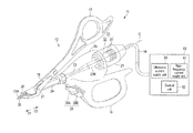
- FIG. 1 is a schematic diagram showing the entire structure of a medical device according to the first embodiment.
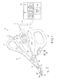
- FIG. 2 is a perspective view showing the distal end portion of the vibration transmission member of the medical device depicted in FIG. 1 and jaw of a clamp arm.
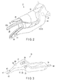
- FIG. 3 is a perspective view showing the clamp arm of the medical device depicted in FIG. 1 .
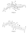
- FIG. 4 is a perspective view showing the conductor of the clamp arm depicted in FIG. 3 .
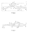
- FIG. 5 is a side view showing how the conductor depicted in FIG. 4 looks like when viewed sideways.
- FIG. 6 is a sectional view showing how the conductor depicted in FIG. 4 is when it is taken along a plane including both the first and second curved portions of the conductor.
- FIG. 7 is a plan view showing how the conductor depicted in FIG. 6 looks like when viewed in the direction of arrow A of FIG. 6 .
- FIG. 8 is a schematic diagram showing the entire structure of a medical device according to the second embodiment.
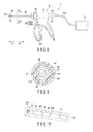
- FIG. 10 is a perspective view showing the conductor of the sheath depicted in FIG. 8 .
- a treatment device 11 an example of a medical device, is provided with a hand piece 12 , a power supply unit 13 , and a cable 14 for connecting the hand piece 12 and the power supply unit 13 .
- the hand piece 12 (assembly unit) is provided with: a resin housing 15 constituting an outer shell; a fixed handle 16 fixed to the housing 15 ; a movable handle 17 movable relative to the housing 15 ; a clamp arm 18 provided on the distal side of the movable handle 17 and being movable together with the movable handle 17 ; a case 21 detachably attached to the housing 15 ; a vibration generator 22 (transducer) stored in the case 21 ; a rod-like vibration transmission member 23 (shaft unit; probe) connected to the vibration generator 22 ; a cylindrical sheath 24 covering the periphery of the vibration transmission member 23 and protecting the vibration transmission member 23 ; a resin cover 26 for covering the back surface opposite to the treatment surface 25 of the vibration transmission member 23 ; a shaft 27 for attaching the clamp arm 18 to the sheath 24 ; and a plurality of operation buttons 28 provided on the housing 15 .
- a resin housing 15 constituting an outer shell
- distal direction C 1 one of the two directions parallel to the longitudinal direction C of the vibration transmission member 23
- proximal direction C 2 one of the two directions parallel to the longitudinal direction C of the vibration transmission member 23
- the clamp arm 18 is an example of a medical member.
- the number of operation buttons 28 is two.
- a first operation button 28 A corresponds to the so-called coagulation mode and is operated when ultrasonic energy and high-frequency energy suitable for the coagulation of a living tissue and the sealing of a blood vessel are to be output.
- a second operation button 28 B corresponds to the so-called coagulation-incision mode and is operated when ultrasonic energy and high-frequency energy suitable for the coagulation and incision of a living tissue and the sealing and incision of a blood vessel are to be output.
- the vibration generator 22 is provided with an ultrasonic transducer 31 and a horn member 32 .
- the ultrasonic transducer 31 includes a plurality of piezoelectric elements for converting a current into ultrasonic vibration.
- One end of an electric wiring line is connected to the ultrasonic transducer 31 .
- the electric line passes through the interior of a cable 14 and is connected, at the other end, to the ultrasonic current supply unit 33 (ultrasonic energy generator) of the power supply unit 13 .
- the ultrasonic current supply unit 33 ultrasonic energy generator
- the ultrasonic transducer 31 is attached to the horn member 32 .
- the horn member 32 is made of a metallic material.
- the horn member 32 includes a substantially cylindrical cross-section changing portion whose cross sectional area decreases in the distal direction C 1 of the vibration transmission member 23 .
- the amplitude of the ultrasonic vibration generated by the ultrasonic transducer 31 increases in the cross-section changing portion.
- the vibration transmission member 23 is a rod-like member made, for example, of a biocompatible material (e.g., a titanium alloy). Ultrasonic vibration used for treatment can be transmitted to the vibration transmission member 23 .
- the vibration transmission member 23 includes a distal end portion 23 A provided at the distal direction (C 1 ) side of the longitudinal direction C and constituting a treatment surface 25 , and a proximal end portion 23 B provided on the opposed side of the distal end portion 23 A.
- the proximal end portion 23 B is connected to one of two second electric wiring lines.
- the vibration transmission member 23 receives ultrasonic vibration transmitted from the vibration generator 22 and also receives a high-frequency current supplied from a high-frequency current supply unit 61 . Therefore, the vibration transmission member 23 (shaft unit) not only applies ultrasonic vibration to a living tissue but also serves as one pole of the bipolar electrode used for bipolar treatment.
- the shaft 27 is formed of a conductive metal and shaped like a pin.
- the proximal portion of the shaft 27 is fitted in a conduction hole 35 (mentioned later) of the clamp arm 18 .
- the shaft 27 can support the clamp arm 18 such that it is movable relative to sheath 24 and the housing 15 .
- the distal end portion of the shaft 27 is pivotally fitted in a depression formed in the sheath 24 .
- a conductor 34 of the clamp arm 18 is electrically connected to the sheath 24 by way of the shaft 27 and the conduction hole 35 .
- the proximal end portion of the sheath 24 is connected to the other one of the two second electric wiring lines.
- a jaw 36 (mentioned later) of the clamp arm 18 is electrically connected to the sheath 24 by way of the shaft 27 mentioned above and the conductor 34 mentioned later. With this structure, the jaw 36 and the conductor 34 supporting the jaw 36 jointly serve as the other pole of the bipolar electrode for bipolar treatment.
- the electrode portion of the jaw 36 is formed, for example, of a copper alloy or the like.
- the clamp arm 18 is an example of a medical member which can be used as a part constituting the treatment device 11 .
- the clamp arm 18 includes: the conductor 34 formed of a conductive metal and shaped substantially like a rod having a curved portion at a halfway position; a coating portion 37 formed integrally with the conductor 34 in such a manner as to cover the surface of the conductor 34 (the whole periphery except for a certain portion); a grasping surface 42 provided at the distal end portion of the conductor 34 ; and a jaw 36 fixed to the grasping surface 42 by mean of a pin 41 .
- the coating portion 37 is integral with the conductor 34 and made by insert molding, by which the conductor 34 is inserted. In the neighborhood of the conductor 34 , the coating portion 37 covers an opposite surface 43 , which is provided opposite to the grasping surface 42 mentioned later.
- the coating portion 37 fills the interior of a first through hole 44 , a second through hole 45 and auxiliary through holes 46 (to be described later) of the conductor 34 .
- the coating portion 37 covers those portions (mentioned later) which are away from the conduction hole 35 of the conductor 34 .
- the coating portion 37 is made, for example, of resin (synthetic resin) having electrical insulation property and heat insulation property.
- the coating portion 37 may be made of PEEK, for example, but may be made of another kind of synthetic resin.
- the heat insulation property mentioned here means that the coefficient of thermal conductivity is sufficiently smaller than that of the conductor 34 (metal) or the like.
- the jaw 36 is fixed to the grasping surface 42 by means of a pin 41 and is swingable relative to a base member, with the pin 41 as a fulcrum.
- the jaw 36 has a contact surface which is depressed in accordance with the projection of the treatment surface 25 of the vibration transmission member 23 .
- the contact surface of the jaw 36 can be brought into engagement with the treatment surface 25 .
- the conductor 34 is an integral member made of stainless steel, for example.
- the conductor 34 may be made of a copper alloy, an aluminum alloy or another kind of conductive metal.
- the conductor 34 includes: a distal end portion 47 ; a proximal end portion 48 opposite to the distal end portion 47 ; a grasping surface 42 formed on the distal end portion ( 47 ) side, brought into contact with a living tissue by means of the jaw 36 and serving to grasp the living tissue; a first surface 51 including the grasping surface 42 ; a second surface 52 provided on the opposite side of the first surface 51 ; a first curved portion 53 provided on the distal end portion ( 47 ) side; a second curved portion 54 provided on the proximal end portion ( 48 ) side; an opening 55 provided (at the boundary) between the first curved portion 53 and the second curved portion 54 ; a pair of side wall portions 56 provided in such a manner as to cover the first curved portion 53 , the opening 55 and the second curved portion 54 ; conduction holes 35 (conduction hole portions) penetrating the side wall portions 56 ; a first through hole 44 (first through hole portion) penetrating the first curved portion 53 ;
- the distal end portion 47 is shaped substantially like “J” such that it conforms with the curve of the treatment surface 25 of the vibration transmission member 23 .
- the first through hole 44 penetrates the first curved portion 53 (first positional shift portion) in the thickness direction thereof and therefore penetrates the first surface 51 and the second surface 52 .
- the second through hole 45 penetrates the second curved portion 54 (second positional shift portion) in the thickness direction thereof and therefore penetrates the first surface 51 and the second surface 52 .
- the first through hole 44 and the second through hole 45 extend along plane P including both the first curved portion 53 and the second curved portion 54 .
- the first curved portion 53 is slightly oblique with respect to the central axis A, and the second curved portion 54 is substantially parallel to the central axis A.
- the first curved portion 53 and the second curved portion 54 are asymmetric portions which are asymmetric with respect to the central axis A.
- the sheath 24 can be passed through the opening 55 .
- the side wall portions 56 are provided to extend from the distal end portion 47 to the proximal end portion 48 .
- the side wall portions 56 are provided with depressed portions 56 A extending in such a manner as to cover the positions of the first curved portion 53 , opening 55 and second curved portion.
- the depressed portions 56 A are continuously provided from the distal end portion 47 to the proximal end portion 48 .
- the conduction holes 35 and a plurality of (two) auxiliary through holes 46 (auxiliary through hole portions), by which the molten resin (coating portion 37 ) can easily flow at the time of molding, are provided at the corresponding positions of the depressed portions 56 A of the side wall portions 56 .
- the auxiliary through holes 46 penetrate the respective side wall portions 56 .
- the first through hole 44 penetrates both the first surface 51 and the second surface 52 in the first curved portion 53 .
- the second through hole 45 penetrates both the first surface 51 and the second surface 52 in the second curved portion 54 .
- the first through hole 44 and the second through hole 45 extend in directions intersecting the central axis A (reference line).
- the first through hole 44 and the second through hole 45 extend in directions intersecting the conduction holes 35 .
- the power supply unit 13 includes an ultrasonic current supply unit 33 (ultrasonic energy supply unit), a high-frequency current supply unit 61 (high-frequency energy supply unit), and a control unit 62 for controlling them.
- the control unit 62 can control the supply of an ultrasonic current generated by the ultrasonic current supply unit 33 and the supply of a high-frequency current generated by the high-frequency current supply unit 61 .
- the operation button 28 is operated by the operator, an electric signal is transmitted to the control unit 62 , and input of an energy operation is detected. Accordingly, the control unit 62 supplies the ultrasonic current from the ultrasonic current supply unit 33 to the vibration transmission member 23 and supplies the high-frequency current from the high-frequency current supply unit 61 to the vibration transmission member 23 .
- the operator holds a living tissue between the vibration transmission member 23 and the jaw 36 of the clamp arm 18 .
- the operator can move the living tissue as in the case where the living tissue is held with forceps, can widen the gap between living tissues, and can perform various other kinds of treatment.
- the operator can apply energy to the held living tissue by operating the operation buttons 28 .
- the vibration transmission member 23 vibrates ultrasonically, so that the thermal energy caused by the frictional motion is applied to the living tissue.
- the temperature of the vibration transmission member 23 increases, for example, to 200° C. or higher.
- the living tissue and blood vessel can be incised between the treatment surface of the vibration transmission member 23 and the jaw. Simultaneously with this, a high-frequency current flows to the living tissue between the treatment surface 25 (serving as an electrode) of the vibration transmission member 23 and the jaw 36 . Accordingly, the living tissue and blood vessel can be coagulated.
- the first operation button 28 A When the first operation button 28 A is operated in the state where the living tissue is held between the vibration transmission member 23 and the jaw 36 , a high-frequency current flows to the living tissue between the treatment surface 25 (serving as an electrode) of the vibration transmission member 23 and the jaw 36 , and electric energy can be applied to the living tissue. Because of this, only the coagulation of the living tissue can be performed.
- the coating portion 37 having heat insulation property is provided on the opposite surface 43 , which is opposite to the grasping surface 42 . Even if the operator unintentionally brings the opposite surface 43 into contact with the neighboring tissues, these tissues are prevented from thermal damage.
- the main portion of the clamp arm 18 can be made by the insert molding in which the conductor 34 is inserted.
- the coating portion 37 can be formed around the conductor 34 .
- the conductor 34 is placed at the predetermined position inside a mold 63 .
- the conductor 34 and the mold 63 are secured using a pin provided for the mold 63 or the like.
- a molten resin is injected into the cavity inside the molds 63 from the side of a gate 64 .
- the gate 64 of the molds 63 is located at the position of the proximal end 48 of the conductor 34 or in the neighborhood of that proximal end 48 .
- the coating portion 37 is formed on the periphery of the conductor 34 (the first surface 51 , the second surface 52 and the surfaces of the side wall portions 56 ).
- the resin can flow through those holes, and an excessive resin pressure is prevented from being applied to only one of the surfaces of the conductor 34 .
- the resin pressure inside the molds 63 is made uniform, and the conductor 34 is prevented from moving inside the molds 63 at the time of injection molding.
- the jaw 36 is fixed to the grasping surface 42 of the conductor 34 using the pin 41 , thereby completing the clamp arm 18 .
- the medical member is assembled with the assembly unit, is movable relative to at least part of the assembly unit, and is provided with: a conductor 34 including a plurality of curved portions and through holes extending along a plane P including the plurality of curved portions; and a coating portion 37 integrally formed with the conductor 34 in such a manner as to cover the periphery of the conductor and fill the interior of the through holes.
- the through holes are provided in the curved portions to which biased pressure tends to be applied when the coating portion 37 is formed, and the coating portion 37 fills the through holes. Therefore, the through holes suppress the biased pressure at the time of molding. Since the conductor 34 is prevented from moving at the time of molding the coating portion 37 , the probability of producing defective products can be lowered and the yield of medical members can be improved.
- the conductor 34 is provided with the first surface 51 including the grasping surface for grasping a living tissue and the second surface 52 opposite to the first surface 51 , and the through holes penetrate both the first surface 51 and the second surface 52 . Even if a pressure difference exists between the first surface 51 and the second surface 52 , the structure mentioned above permits the pressure on one side to be transmitted to the other side via the through holes.
- the yield of medical members can be improved by providing a simple structure (through holes) in the conductor 34 .
- the conductor 34 includes positional shift portions which are shifted from the central axis A of the conductor 34 , and the through holes are provided in such a manner as to penetrate the positional shift portions in the thickness direction thereof.
- the though holes serve to eliminate the pressure difference in the positional shift portions where non-uniform pressure tends to be generated at the time of molding the coating portion. Therefore, the conductor 34 is prevented from moving at the time of molding, and the yield of medical members can be improved.
- the conductor 34 includes the conduction holes 35 , and the conductor 34 is electrically connected to the assembly unit by way of the conduction holes 35 and the shaft 27 inserted through the conduction holes 35 .
- the conductor 34 is supported such that it is movable relative to at least part of the assembly unit, and the coating portion 37 covers portions which are away from the conduction hole 35 .
- the assembly unit is provided with the shaft unit which receives high-frequency energy transmitted thereto and which constitutes one pole when the high-frequency energy is applied to a living tissue.
- the conductor 34 constitutes the other pole when the high-frequency energy is applied to the living tissue.
- a high-frequency treatment is enabled in which high-frequency is applied to a living tissue located between the shaft unit and the conductor 34 .
- the conductor 34 is provided with the opposite surface 43 on the opposite side of the grasping surface 42 , and the coating portion 37 is formed of a heat insulating resin and covers at least the opposite surface 43 .
- the temperatures of the shaft unit and the conductor 34 become comparatively high.
- the coating portion 37 should be formed of a resin having electrical insulation property. Where the coating portion 37 has electrical insulation property, a current is prevented from leaking and flowing to the neighboring tissues when the living tissue to be treated is applied with high-frequency energy. Accordingly, a medical member can be provided which causes little damage to the neighboring tissues.
- the conductor 34 includes wall portions extending from the distal end portion 47 thereof to the proximal end portion 48 opposite to the distal end portion 47 , and depressed portions 56 A provided in the respective wall portions and continuously provided from the distal end portion 47 to the proximal end portion 48 . Since the depressed portions 56 A are provided, a resin can easily flow when the coating portion 37 is molded, and non-uniform resin pressure is prevented.
- the conductor 34 is provided with auxiliary through holes 46 which penetrate the respective wall portions and which are located at positions corresponding to the depressed portions 56 A. Since the wall portions are provided with the auxiliary through holes 46 in addition to the depressed portions 56 A, the resin pressure can be made uniform between the obverse side of each wall portion and the reverse side thereof. Because of this, the yield of medical members can be improved.
- a medical device of the second embodiment of the present invention will be described with reference to FIGS. 8 to 10 .
- a treatment device 11 an example of the medical device of the second embodiment, differs from that of the first embodiment in terms of the shape of a hand piece 12 employed, but the other features are similar to those of the first embodiment.
- a description will therefore be given mainly of how the second embodiment differs from the first embodiment.
- a description and illustration of them will be omitted.
- one of the two directions parallel to the longitudinal direction C of the vibration transmission member 23 will be referred to as distal direction C 1
- the direction opposite to the distal direction C 1 will be referred to as proximal direction C 2 .
- the hand piece 12 (assembly unit) is provided with: a resin housing 15 constituting an outer shell; a fixed handle 16 fixed to the housing 15 ; a movable handle 17 movable relative to the housing 15 ; a case 21 detachably attached to the housing 15 ; a vibration generator 22 (transducer) stored in the case 21 ; a rod-like vibration transmission member 23 (shaft unit; probe) connected to the vibration generator 22 ; a cylindrical sheath 24 covering the periphery of the vibration transmission member 23 and protecting the vibration transmission member 23 ; a jaw 36 provided at the distal end portion of the sheath 24 and being rotatable relative to the sheath 24 ; a cylindrical driving pipe provided inside the sheath 24 and being movable back and forth when the jaw 36 is opened or closed; a knob 65 (rotating knob) fixed to the sheath 24 ; and a plurality of operation buttons 28 provided on the housing 15 .
- the sheath 24 is an example of a medical
- the sheath 24 is cylindrical and protects the vibration transmission member 23 located therein.
- the sheath 24 is attached to the housing 15 such that it is rotatable with reference to the housing 15 .
- the sheath 24 includes, at the distal end portion thereof, a support pin used for rotatably supporting the jaw 36 .
- One of electric wiring lines connected to the power supply unit 13 is connected to the proximal end portion of the sheath 24 .
- the jaw 36 is electrically connected to the sheath 24 . Therefore, the jaw 36 at the distal end portion of the sheath 24 serves as one of the poles of the bipolar electrode for bipolar treatment.
- the vibration transmission member 23 is connected to the other one of the electric wiring lines connected to the power supply unit 13 , and serves as the other pole of the bipolar electrode for bipolar treatment.
- the sheath 24 includes a cylindrical conductor 34 , and a coating portion 37 covering both the inner peripheral surface and outer peripheral surface of the conductor 34 .
- the coating portion 37 is integral with the conductor 34 and made by insert molding, in which the conductor 34 is inserted.
- the coating portion 37 is made, for example, of resin (synthetic resin) having electrical insulation property and heat insulation property.
- resin synthetic resin
- the heat insulation property mentioned here means that the coefficient of thermal conductivity is sufficiently smaller than that of the conductor 34 (metal) or the like.
- the conductor 34 is an integral member made of stainless steel, for example.
- the conductor 34 may be made of a copper alloy, an aluminum alloy or another kind of conductive metal.
- the conductor 34 includes a conductor main body 66 and a plurality of through holes 67 (through hole portions) penetrating the conductor main body 66 .
- the conductor 34 is placed at the predetermined position in a mold 63 .
- the conductor 34 and the mold 63 are secured using a pin provided for the mold 63 or the like.
- a molten resin is injected into the cavity inside the molds 63 from the side of a gate 64 .
- the gate 64 of the molds 63 is located at the position of the proximal end portion 48 of the conductor 34 or in the neighborhood of that proximal end portion 48 .
- the coating portion 37 is formed on the periphery of the conductor 34 (the inner peripheral surface and the outer peripheral surface).
- the resin can flow through these holes, and an excessive resin pressure is prevented from being applied to only one of the outer and inner peripheral surfaces of the conductor 34 .
- the resin pressure inside the molds 63 is made uniform, and the conductor is prevented from moving inside the molds 63 at the time of mold injection.
- the jaw 36 is fixed to the distal end portion of the sheath 24 using the support pin, thereby completing the sheath 24 .
- the medical member is cylindrical, non-uniform pressure is prevented at the time of molding the coating portion 37 . Since the conductor 34 is prevented from moving at the time of molding, the yield of medical members can be improved.
- the present invention is not limited to the above-described embodiments, and can be modified in various manners in practice without departing from the gist of the invention.
- one medical device can be made by properly combining the medical devices of the above embodiments.
Landscapes
- Health & Medical Sciences (AREA)
- Engineering & Computer Science (AREA)
- Life Sciences & Earth Sciences (AREA)
- Surgery (AREA)
- Biomedical Technology (AREA)
- Nuclear Medicine, Radiotherapy & Molecular Imaging (AREA)
- Animal Behavior & Ethology (AREA)
- General Health & Medical Sciences (AREA)
- Public Health (AREA)
- Veterinary Medicine (AREA)
- Medical Informatics (AREA)
- Heart & Thoracic Surgery (AREA)
- Molecular Biology (AREA)
- Plasma & Fusion (AREA)
- Otolaryngology (AREA)
- Physics & Mathematics (AREA)
- Dentistry (AREA)
- Mechanical Engineering (AREA)
- Surgical Instruments (AREA)
- Radiology & Medical Imaging (AREA)
Abstract
Description
- This application is a Continuation Application of PCT Application No. PCT/JP2016/066928, filed Jun. 7, 2016 and based upon and claiming the benefit of priority from prior Japanese Patent Application No. 2015-127765, filed Jun. 25, 2015, the entire contents of all of which are incorporated herein by reference.
- The present invention relates to a medical member for use in a medical device with which to treat an object to be treated.
- An endoscopic biopsy forceps device is disclosed in Jpn. Pat. Appln. KOKAI No. 2005-193061 (patent literature 1). This ultrasonic treatment device includes opposed jaws, and the opposed jaws can be coupled to an electric cauterization power supply through a wire.
- A medical member according to an embodiment of the present invention is assembled with an assembly unit, is movable relative to at least part of the assembly unit, and is provided with: a conductor extending along a plane including a plurality of curved portions and a through hole extending along a plane including the plurality of curved portions; and a coating portion integrally formed with the conductor in such a manner as to cover the periphery of the conductor and fill the interior of the through hole.
- Advantages of the invention will be set forth in the description which follows, and in part will be obvious from the description, or may be learned by practice of the invention. Advantages of the invention may be realized and obtained by means of the instrumentalities and combinations particularly pointed out hereinafter.
- The accompanying drawings, which are incorporated in and constitute a part of the specification, illustrate embodiments of the invention, and together with the general description given above and the detailed description of the embodiments given below, serve to explain the principles of the invention.
-
FIG. 1 is a schematic diagram showing the entire structure of a medical device according to the first embodiment. -
FIG. 2 is a perspective view showing the distal end portion of the vibration transmission member of the medical device depicted inFIG. 1 and jaw of a clamp arm. -
FIG. 3 is a perspective view showing the clamp arm of the medical device depicted inFIG. 1 . -
FIG. 4 is a perspective view showing the conductor of the clamp arm depicted inFIG. 3 . -
FIG. 5 is a side view showing how the conductor depicted inFIG. 4 looks like when viewed sideways. -
FIG. 6 is a sectional view showing how the conductor depicted inFIG. 4 is when it is taken along a plane including both the first and second curved portions of the conductor. -
FIG. 7 is a plan view showing how the conductor depicted inFIG. 6 looks like when viewed in the direction of arrow A ofFIG. 6 . -
FIG. 8 is a schematic diagram showing the entire structure of a medical device according to the second embodiment. -
FIG. 9 is a sectional view taken along line F9-F9 of the medical device shown inFIG. 10 . -
FIG. 10 is a perspective view showing the conductor of the sheath depicted inFIG. 8 . - A medical device of the first embodiment of the present invention will be described with reference to
FIGS. 1 to 7 . - As shown in
FIG. 1 , atreatment device 11, an example of a medical device, is provided with ahand piece 12, apower supply unit 13, and acable 14 for connecting thehand piece 12 and thepower supply unit 13. - As shown in
FIGS. 1 to 3 , the hand piece 12 (assembly unit) is provided with: aresin housing 15 constituting an outer shell; afixed handle 16 fixed to thehousing 15; amovable handle 17 movable relative to thehousing 15; aclamp arm 18 provided on the distal side of themovable handle 17 and being movable together with themovable handle 17; acase 21 detachably attached to thehousing 15; a vibration generator 22 (transducer) stored in thecase 21; a rod-like vibration transmission member 23 (shaft unit; probe) connected to thevibration generator 22; acylindrical sheath 24 covering the periphery of thevibration transmission member 23 and protecting thevibration transmission member 23; aresin cover 26 for covering the back surface opposite to thetreatment surface 25 of thevibration transmission member 23; ashaft 27 for attaching theclamp arm 18 to thesheath 24; and a plurality ofoperation buttons 28 provided on thehousing 15. In the present embodiment, one of the two directions parallel to the longitudinal direction C of thevibration transmission member 23 will be referred to as distal direction C1, and the direction opposite to the distal direction C1 will be referred to as proximal direction C2. Theclamp arm 18 is an example of a medical member. - In the present embodiment, the number of
operation buttons 28 is two. Afirst operation button 28A corresponds to the so-called coagulation mode and is operated when ultrasonic energy and high-frequency energy suitable for the coagulation of a living tissue and the sealing of a blood vessel are to be output. Asecond operation button 28B corresponds to the so-called coagulation-incision mode and is operated when ultrasonic energy and high-frequency energy suitable for the coagulation and incision of a living tissue and the sealing and incision of a blood vessel are to be output. - As shown in
FIG. 1 , thevibration generator 22 is provided with anultrasonic transducer 31 and ahorn member 32. Theultrasonic transducer 31 includes a plurality of piezoelectric elements for converting a current into ultrasonic vibration. One end of an electric wiring line is connected to theultrasonic transducer 31. The electric line passes through the interior of acable 14 and is connected, at the other end, to the ultrasonic current supply unit 33 (ultrasonic energy generator) of thepower supply unit 13. When power is supplied from the ultrasoniccurrent supply unit 33 to theultrasonic transducer 31 through the electric wiring line, theultrasonic transducer 31 generates ultrasonic vibration. - As shown in
FIG. 1 , theultrasonic transducer 31 is attached to thehorn member 32. Thehorn member 32 is made of a metallic material. Thehorn member 32 includes a substantially cylindrical cross-section changing portion whose cross sectional area decreases in the distal direction C1 of thevibration transmission member 23. The amplitude of the ultrasonic vibration generated by theultrasonic transducer 31 increases in the cross-section changing portion. - As shown in
FIG. 2 , thevibration transmission member 23 is a rod-like member made, for example, of a biocompatible material (e.g., a titanium alloy). Ultrasonic vibration used for treatment can be transmitted to thevibration transmission member 23. Thevibration transmission member 23 includes adistal end portion 23A provided at the distal direction (C1) side of the longitudinal direction C and constituting atreatment surface 25, and aproximal end portion 23B provided on the opposed side of thedistal end portion 23A. Theproximal end portion 23B is connected to one of two second electric wiring lines. Thevibration transmission member 23 receives ultrasonic vibration transmitted from thevibration generator 22 and also receives a high-frequency current supplied from a high-frequencycurrent supply unit 61. Therefore, the vibration transmission member 23 (shaft unit) not only applies ultrasonic vibration to a living tissue but also serves as one pole of the bipolar electrode used for bipolar treatment. - The
shaft 27 is formed of a conductive metal and shaped like a pin. The proximal portion of theshaft 27 is fitted in a conduction hole 35 (mentioned later) of theclamp arm 18. As shown inFIG. 2 etc., theshaft 27 can support theclamp arm 18 such that it is movable relative tosheath 24 and thehousing 15. In other words, the distal end portion of theshaft 27 is pivotally fitted in a depression formed in thesheath 24. Aconductor 34 of theclamp arm 18 is electrically connected to thesheath 24 by way of theshaft 27 and theconduction hole 35. - The proximal end portion of the
sheath 24 is connected to the other one of the two second electric wiring lines. A jaw 36 (mentioned later) of theclamp arm 18 is electrically connected to thesheath 24 by way of theshaft 27 mentioned above and theconductor 34 mentioned later. With this structure, thejaw 36 and theconductor 34 supporting thejaw 36 jointly serve as the other pole of the bipolar electrode for bipolar treatment. The electrode portion of thejaw 36 is formed, for example, of a copper alloy or the like. - As shown in
FIG. 1 toFIG. 3 , theclamp arm 18 is an example of a medical member which can be used as a part constituting thetreatment device 11. Theclamp arm 18 includes: theconductor 34 formed of a conductive metal and shaped substantially like a rod having a curved portion at a halfway position; acoating portion 37 formed integrally with theconductor 34 in such a manner as to cover the surface of the conductor 34 (the whole periphery except for a certain portion); agrasping surface 42 provided at the distal end portion of theconductor 34; and ajaw 36 fixed to thegrasping surface 42 by mean of apin 41. - As shown in
FIG. 3 , thecoating portion 37 is integral with theconductor 34 and made by insert molding, by which theconductor 34 is inserted. In the neighborhood of theconductor 34, thecoating portion 37 covers anopposite surface 43, which is provided opposite to the graspingsurface 42 mentioned later. Thecoating portion 37 fills the interior of a first throughhole 44, a second throughhole 45 and auxiliary through holes 46 (to be described later) of theconductor 34. Thecoating portion 37 covers those portions (mentioned later) which are away from theconduction hole 35 of theconductor 34. Thecoating portion 37 is made, for example, of resin (synthetic resin) having electrical insulation property and heat insulation property. Thecoating portion 37 may be made of PEEK, for example, but may be made of another kind of synthetic resin. The heat insulation property mentioned here means that the coefficient of thermal conductivity is sufficiently smaller than that of the conductor 34 (metal) or the like. - The
jaw 36 is fixed to the graspingsurface 42 by means of apin 41 and is swingable relative to a base member, with thepin 41 as a fulcrum. Thejaw 36 has a contact surface which is depressed in accordance with the projection of thetreatment surface 25 of thevibration transmission member 23. The contact surface of thejaw 36 can be brought into engagement with thetreatment surface 25. - As shown in
FIGS. 4 to 7 , theconductor 34 is an integral member made of stainless steel, for example. Theconductor 34 may be made of a copper alloy, an aluminum alloy or another kind of conductive metal. - The
conductor 34 includes: adistal end portion 47; aproximal end portion 48 opposite to thedistal end portion 47; a graspingsurface 42 formed on the distal end portion (47) side, brought into contact with a living tissue by means of thejaw 36 and serving to grasp the living tissue; afirst surface 51 including the graspingsurface 42; asecond surface 52 provided on the opposite side of thefirst surface 51; a firstcurved portion 53 provided on the distal end portion (47) side; a secondcurved portion 54 provided on the proximal end portion (48) side; anopening 55 provided (at the boundary) between the firstcurved portion 53 and the secondcurved portion 54; a pair ofside wall portions 56 provided in such a manner as to cover the firstcurved portion 53, theopening 55 and the secondcurved portion 54; conduction holes 35 (conduction hole portions) penetrating theside wall portions 56; a first through hole 44 (first through hole portion) penetrating the firstcurved portion 53; and a second through hole 45 (second through hole portion) penetrating the secondcurved portion 54. - The
distal end portion 47 is shaped substantially like “J” such that it conforms with the curve of thetreatment surface 25 of thevibration transmission member 23. The first throughhole 44 penetrates the first curved portion 53 (first positional shift portion) in the thickness direction thereof and therefore penetrates thefirst surface 51 and thesecond surface 52. The second throughhole 45 penetrates the second curved portion 54 (second positional shift portion) in the thickness direction thereof and therefore penetrates thefirst surface 51 and thesecond surface 52. As shown inFIG. 6 , the first throughhole 44 and the second throughhole 45 extend along plane P including both the firstcurved portion 53 and the secondcurved portion 54. - As shown in
FIG. 6 , the first curved portion 53 (first positional shift portion) and the second curved portion 54 (second positional shift portion) are shifted from the central axis (reference line) of theconductor 34. The firstcurved portion 53 and the secondcurved portion 54 are portions by which the rigidity of theclamp arm 18 is ensured. The firstcurved portion 53 and the secondcurved portion 54 extend along the central axis A. In the present embodiment, the expression “along the central axis A” is intended to mean both being substantially parallel to the central axis A and being slightly slanted with respect to the central axis A. In the present embodiment, as shown inFIG. 6 , the firstcurved portion 53 is slightly oblique with respect to the central axis A, and the secondcurved portion 54 is substantially parallel to the central axis A. The firstcurved portion 53 and the secondcurved portion 54 are asymmetric portions which are asymmetric with respect to the central axis A. Thesheath 24 can be passed through theopening 55. - As shown in
FIGS. 4 and 5 , theside wall portions 56 are provided to extend from thedistal end portion 47 to theproximal end portion 48. Theside wall portions 56 are provided withdepressed portions 56A extending in such a manner as to cover the positions of the firstcurved portion 53, opening 55 and second curved portion. Thedepressed portions 56A are continuously provided from thedistal end portion 47 to theproximal end portion 48. The conduction holes 35 and a plurality of (two) auxiliary through holes 46 (auxiliary through hole portions), by which the molten resin (coating portion 37) can easily flow at the time of molding, are provided at the corresponding positions of thedepressed portions 56A of theside wall portions 56. The auxiliary throughholes 46 penetrate the respectiveside wall portions 56. - As shown in
FIG. 6 , the first throughhole 44 penetrates both thefirst surface 51 and thesecond surface 52 in the firstcurved portion 53. The second throughhole 45 penetrates both thefirst surface 51 and thesecond surface 52 in the secondcurved portion 54. The first throughhole 44 and the second throughhole 45 extend in directions intersecting the central axis A (reference line). The first throughhole 44 and the second throughhole 45 extend in directions intersecting the conduction holes 35. - As shown in
FIG. 1 , thepower supply unit 13 includes an ultrasonic current supply unit 33 (ultrasonic energy supply unit), a high-frequency current supply unit 61 (high-frequency energy supply unit), and acontrol unit 62 for controlling them. Thecontrol unit 62 can control the supply of an ultrasonic current generated by the ultrasoniccurrent supply unit 33 and the supply of a high-frequency current generated by the high-frequencycurrent supply unit 61. When theoperation button 28 is operated by the operator, an electric signal is transmitted to thecontrol unit 62, and input of an energy operation is detected. Accordingly, thecontrol unit 62 supplies the ultrasonic current from the ultrasoniccurrent supply unit 33 to thevibration transmission member 23 and supplies the high-frequency current from the high-frequencycurrent supply unit 61 to thevibration transmission member 23. - A description will be given of an operation of the medical device of the present embodiment with reference to
FIG. 2 . - Where an object to be treated exists, the operator holds a living tissue between the
vibration transmission member 23 and thejaw 36 of theclamp arm 18. The operator can move the living tissue as in the case where the living tissue is held with forceps, can widen the gap between living tissues, and can perform various other kinds of treatment. The operator can apply energy to the held living tissue by operating theoperation buttons 28. When thesecond operation button 28B corresponding to the coagulation-incision mode is operated, thevibration transmission member 23 vibrates ultrasonically, so that the thermal energy caused by the frictional motion is applied to the living tissue. At the time, the temperature of thevibration transmission member 23 increases, for example, to 200° C. or higher. Because of this, the living tissue and blood vessel can be incised between the treatment surface of thevibration transmission member 23 and the jaw. Simultaneously with this, a high-frequency current flows to the living tissue between the treatment surface 25 (serving as an electrode) of thevibration transmission member 23 and thejaw 36. Accordingly, the living tissue and blood vessel can be coagulated. - In this manner, two kinds of energy are applied from the
vibration transmission member 23 and thejaw 36 in the present embodiment, and the living tissue held between them can be coagulated or incised with high efficiency. - When the
first operation button 28A is operated in the state where the living tissue is held between thevibration transmission member 23 and thejaw 36, a high-frequency current flows to the living tissue between the treatment surface 25 (serving as an electrode) of thevibration transmission member 23 and thejaw 36, and electric energy can be applied to the living tissue. Because of this, only the coagulation of the living tissue can be performed. - In the present embodiment, the
coating portion 37 having heat insulation property is provided on theopposite surface 43, which is opposite to the graspingsurface 42. Even if the operator unintentionally brings theopposite surface 43 into contact with the neighboring tissues, these tissues are prevented from thermal damage. - A description will be given of the manufacturing process of the
clamp arm 18 of the present embodiment with reference toFIG. 5 etc. The main portion of theclamp arm 18 can be made by the insert molding in which theconductor 34 is inserted. By this insert molding, thecoating portion 37 can be formed around theconductor 34. - To be specific, the
conductor 34 is placed at the predetermined position inside amold 63. Preferably, theconductor 34 and themold 63 are secured using a pin provided for themold 63 or the like. After a pair ofmolds 63 are placed one on the other, a molten resin is injected into the cavity inside themolds 63 from the side of agate 64. At the time, thegate 64 of themolds 63 is located at the position of theproximal end 48 of theconductor 34 or in the neighborhood of thatproximal end 48. By this insert molding, thecoating portion 37 is formed on the periphery of the conductor 34 (thefirst surface 51, thesecond surface 52 and the surfaces of the side wall portions 56). Since the first throughhole 44, the second throughhole 45 and the auxiliary throughholes 46 are provided in theconductor 34, the resin can flow through those holes, and an excessive resin pressure is prevented from being applied to only one of the surfaces of theconductor 34. As a result, the resin pressure inside themolds 63 is made uniform, and theconductor 34 is prevented from moving inside themolds 63 at the time of injection molding. - After the
coating portion 37 is formed on theconductor 34 in the manner mentioned above, thejaw 36 is fixed to the graspingsurface 42 of theconductor 34 using thepin 41, thereby completing theclamp arm 18. - According to the first embodiment, the medical member is assembled with the assembly unit, is movable relative to at least part of the assembly unit, and is provided with: a
conductor 34 including a plurality of curved portions and through holes extending along a plane P including the plurality of curved portions; and acoating portion 37 integrally formed with theconductor 34 in such a manner as to cover the periphery of the conductor and fill the interior of the through holes. - With this structure, the through holes are provided in the curved portions to which biased pressure tends to be applied when the
coating portion 37 is formed, and thecoating portion 37 fills the through holes. Therefore, the through holes suppress the biased pressure at the time of molding. Since theconductor 34 is prevented from moving at the time of molding thecoating portion 37, the probability of producing defective products can be lowered and the yield of medical members can be improved. - The
conductor 34 is provided with thefirst surface 51 including the grasping surface for grasping a living tissue and thesecond surface 52 opposite to thefirst surface 51, and the through holes penetrate both thefirst surface 51 and thesecond surface 52. Even if a pressure difference exists between thefirst surface 51 and thesecond surface 52, the structure mentioned above permits the pressure on one side to be transmitted to the other side via the through holes. The yield of medical members can be improved by providing a simple structure (through holes) in theconductor 34. - The
conductor 34 includes positional shift portions which are shifted from the central axis A of theconductor 34, and the through holes are provided in such a manner as to penetrate the positional shift portions in the thickness direction thereof. With this structure, the though holes serve to eliminate the pressure difference in the positional shift portions where non-uniform pressure tends to be generated at the time of molding the coating portion. Therefore, theconductor 34 is prevented from moving at the time of molding, and the yield of medical members can be improved. - The
coating portion 37 is formed of an insulating resin, and thegate 64 used for molding thecoating portion 37 is provided at theproximal end portion 48 of theconductor 34, which is opposite to thedistal end portion 47. In general, a molded article tends to have burrs in the neighborhood of thegate 64. Although the burrs can be removed using a cutter or the like, minute irregularities may remain on the cut portions. With the structure mentioned above, since thegate 64 is located at theproximal end portion 48, irregularities are prevented from remaining on thecoating portion 37 in the neighborhood of thedistal end portion 47. Therefore, the external shape and thickness of thecoating portion 37 are stable in the neighborhood of thedistal end portion 47, with which a fine treatment is performed in a living body. As a result, a medical member with high quality can be provided. - The
conductor 34 includes the conduction holes 35, and theconductor 34 is electrically connected to the assembly unit by way of the conduction holes 35 and theshaft 27 inserted through the conduction holes 35. In addition, theconductor 34 is supported such that it is movable relative to at least part of the assembly unit, and thecoating portion 37 covers portions which are away from theconduction hole 35. - With this structure, electrical conduction to the assembly unit can be attained through the conduction holes 35, and the
coating portion 37 does not hinder the electrical connection between theconductor 34 and the assembly unit. - The conduction holes 35 are provided to extend in a direction intersecting the through holes. With this structure, the conduction holes 35 extend in the direction in which non-uniform pressure is hard to generate at the time of molding (namely, in a direction in which the through holes do not extend). Since non-uniform pressure is not generated in the neighborhood of the conduction holes 35, and the
conductor 34 is prevented from moving at the time of molding, the yield of medical members can be improved. - The assembly unit is provided with the shaft unit which receives high-frequency energy transmitted thereto and which constitutes one pole when the high-frequency energy is applied to a living tissue. The
conductor 34 constitutes the other pole when the high-frequency energy is applied to the living tissue. - With this structure, a high-frequency treatment is enabled in which high-frequency is applied to a living tissue located between the shaft unit and the
conductor 34. Theconductor 34 is provided with theopposite surface 43 on the opposite side of the graspingsurface 42, and thecoating portion 37 is formed of a heat insulating resin and covers at least theopposite surface 43. For example, when a treatment in which high-frequency energy is applied to a living tissue is performed, the temperatures of the shaft unit and theconductor 34 become comparatively high. With the structure of the embodiment, even if the operator unintentionally brings theopposite surface 43 into contact with the neighboring tissues, these tissues are prevented from being thermally damaged. - Preferably, the
coating portion 37 should be formed of a resin having electrical insulation property. Where thecoating portion 37 has electrical insulation property, a current is prevented from leaking and flowing to the neighboring tissues when the living tissue to be treated is applied with high-frequency energy. Accordingly, a medical member can be provided which causes little damage to the neighboring tissues. - The
conductor 34 includes wall portions extending from thedistal end portion 47 thereof to theproximal end portion 48 opposite to thedistal end portion 47, anddepressed portions 56A provided in the respective wall portions and continuously provided from thedistal end portion 47 to theproximal end portion 48. Since thedepressed portions 56A are provided, a resin can easily flow when thecoating portion 37 is molded, and non-uniform resin pressure is prevented. - The
conductor 34 is provided with auxiliary throughholes 46 which penetrate the respective wall portions and which are located at positions corresponding to thedepressed portions 56A. Since the wall portions are provided with the auxiliary throughholes 46 in addition to thedepressed portions 56A, the resin pressure can be made uniform between the obverse side of each wall portion and the reverse side thereof. Because of this, the yield of medical members can be improved. - A medical device of the second embodiment of the present invention will be described with reference to
FIGS. 8 to 10 . Atreatment device 11, an example of the medical device of the second embodiment, differs from that of the first embodiment in terms of the shape of ahand piece 12 employed, but the other features are similar to those of the first embodiment. A description will therefore be given mainly of how the second embodiment differs from the first embodiment. As for the features common to the first embodiment, a description and illustration of them will be omitted. In the present embodiment, one of the two directions parallel to the longitudinal direction C of thevibration transmission member 23 will be referred to as distal direction C1, and the direction opposite to the distal direction C1 will be referred to as proximal direction C2. - As shown in
FIG. 8 , the hand piece 12 (assembly unit) is provided with: aresin housing 15 constituting an outer shell; a fixedhandle 16 fixed to thehousing 15; amovable handle 17 movable relative to thehousing 15; acase 21 detachably attached to thehousing 15; a vibration generator 22 (transducer) stored in thecase 21; a rod-like vibration transmission member 23 (shaft unit; probe) connected to thevibration generator 22; acylindrical sheath 24 covering the periphery of thevibration transmission member 23 and protecting thevibration transmission member 23; ajaw 36 provided at the distal end portion of thesheath 24 and being rotatable relative to thesheath 24; a cylindrical driving pipe provided inside thesheath 24 and being movable back and forth when thejaw 36 is opened or closed; a knob 65 (rotating knob) fixed to thesheath 24; and a plurality ofoperation buttons 28 provided on thehousing 15. Thesheath 24 is an example of a medical member. - The
sheath 24 is cylindrical and protects thevibration transmission member 23 located therein. Thesheath 24 is attached to thehousing 15 such that it is rotatable with reference to thehousing 15. Thesheath 24 includes, at the distal end portion thereof, a support pin used for rotatably supporting thejaw 36. One of electric wiring lines connected to thepower supply unit 13 is connected to the proximal end portion of thesheath 24. Thejaw 36 is electrically connected to thesheath 24. Therefore, thejaw 36 at the distal end portion of thesheath 24 serves as one of the poles of the bipolar electrode for bipolar treatment. Thevibration transmission member 23 is connected to the other one of the electric wiring lines connected to thepower supply unit 13, and serves as the other pole of the bipolar electrode for bipolar treatment. - As shown in
FIG. 10 , thesheath 24 includes acylindrical conductor 34, and acoating portion 37 covering both the inner peripheral surface and outer peripheral surface of theconductor 34. Thecoating portion 37 is integral with theconductor 34 and made by insert molding, in which theconductor 34 is inserted. Thecoating portion 37 is made, for example, of resin (synthetic resin) having electrical insulation property and heat insulation property. The heat insulation property mentioned here means that the coefficient of thermal conductivity is sufficiently smaller than that of the conductor 34 (metal) or the like. - The
conductor 34 is an integral member made of stainless steel, for example. Theconductor 34 may be made of a copper alloy, an aluminum alloy or another kind of conductive metal. Theconductor 34 includes a conductormain body 66 and a plurality of through holes 67 (through hole portions) penetrating the conductormain body 66. - A description will be given of the manufacturing process of the
sheath 24 of thehand piece 12 of the present embodiment with reference toFIG. 10 etc. - First of all, the
conductor 34 is placed at the predetermined position in amold 63. Preferably, theconductor 34 and themold 63 are secured using a pin provided for themold 63 or the like. After a pair ofmolds 63 are placed one on the other, a molten resin is injected into the cavity inside themolds 63 from the side of agate 64. At the time, thegate 64 of themolds 63 is located at the position of theproximal end portion 48 of theconductor 34 or in the neighborhood of thatproximal end portion 48. By this insert molding, thecoating portion 37 is formed on the periphery of the conductor 34 (the inner peripheral surface and the outer peripheral surface). Since a plurality of throughholes 67 are provided in theconductor 34, the resin can flow through these holes, and an excessive resin pressure is prevented from being applied to only one of the outer and inner peripheral surfaces of theconductor 34. As a result, the resin pressure inside themolds 63 is made uniform, and the conductor is prevented from moving inside themolds 63 at the time of mold injection. - After the
coating portion 37 is formed on theconductor 34 in the manner mentioned above, thejaw 36 is fixed to the distal end portion of thesheath 24 using the support pin, thereby completing thesheath 24. - According to the present embodiment, even where the medical member is cylindrical, non-uniform pressure is prevented at the time of molding the
coating portion 37. Since theconductor 34 is prevented from moving at the time of molding, the yield of medical members can be improved. - The present invention is not limited to the above-described embodiments, and can be modified in various manners in practice without departing from the gist of the invention. In addition, one medical device can be made by properly combining the medical devices of the above embodiments.
- Additional advantages and modifications will readily occur to those skilled in the art. Therefore, the invention in its broader aspects is not limited to the specific details and representative embodiments shown and described herein. Accordingly, various modifications may be made without departing from the spirit or scope of the general inventive concept as defined by the appended claims and their equivalents.
Claims (14)
Applications Claiming Priority (4)
| Application Number | Priority Date | Filing Date | Title |
|---|---|---|---|
| JP2015-127765 | 2015-06-25 | ||
| JP2015127765 | 2015-06-25 | ||
| JPJP2015-127765 | 2015-06-25 | ||
| PCT/JP2016/066928 WO2016208384A1 (en) | 2015-06-25 | 2016-06-07 | Medical member and medical equipment |
Related Parent Applications (1)
| Application Number | Title | Priority Date | Filing Date |
|---|---|---|---|
| PCT/JP2016/066928 Continuation WO2016208384A1 (en) | 2015-06-25 | 2016-06-07 | Medical member and medical equipment |
Publications (2)
| Publication Number | Publication Date |
|---|---|
| US20180098809A1 true US20180098809A1 (en) | 2018-04-12 |
| US11103300B2 US11103300B2 (en) | 2021-08-31 |
Family
ID=57585570
Family Applications (1)
| Application Number | Title | Priority Date | Filing Date |
|---|---|---|---|
| US15/837,219 Active 2038-10-08 US11103300B2 (en) | 2015-06-25 | 2017-12-11 | Medical member and medical device |
Country Status (3)
| Country | Link |
|---|---|
| US (1) | US11103300B2 (en) |
| JP (1) | JP6153686B2 (en) |
| WO (1) | WO2016208384A1 (en) |
Cited By (4)
| Publication number | Priority date | Publication date | Assignee | Title |
|---|---|---|---|---|
| US11452560B2 (en) | 2017-07-14 | 2022-09-27 | Olympus Corporation | Treatment tool with jaws |
| US20220323089A1 (en) * | 2020-06-30 | 2022-10-13 | Olympus Corporation | Vibration transmission member, ultrasound treatment tool, and method of manufacturing vibration transmission member |
| WO2025017461A1 (en) * | 2023-07-17 | 2025-01-23 | Cilag Gmbh International | Surgical instrument with clamp arm and pivot shaft hinge coupling |
| US12357338B2 (en) | 2020-08-04 | 2025-07-15 | Olympus Corporation | Ultrasonic treatment tool and method of manufacturing ultrasonic treatment tool |
Family Cites Families (5)
| Publication number | Priority date | Publication date | Assignee | Title |
|---|---|---|---|---|
| US5482054A (en) * | 1990-05-10 | 1996-01-09 | Symbiosis Corporation | Edoscopic biopsy forceps devices with selective bipolar cautery |
| US5396900A (en) * | 1991-04-04 | 1995-03-14 | Symbiosis Corporation | Endoscopic end effectors constructed from a combination of conductive and non-conductive materials and useful for selective endoscopic cautery |
| WO1994017741A1 (en) * | 1993-02-11 | 1994-08-18 | Symbiosis Corporation | Endoscopic biopsy forceps devices with selective bipolar cautery |
| JP4727575B2 (en) | 2004-06-15 | 2011-07-20 | オリンパス株式会社 | Energy treatment tool |
| JP5498624B2 (en) | 2011-10-26 | 2014-05-21 | オリンパスメディカルシステムズ株式会社 | Ultrasonic treatment device |
-
2016
- 2016-06-07 JP JP2017501343A patent/JP6153686B2/en active Active
- 2016-06-07 WO PCT/JP2016/066928 patent/WO2016208384A1/en not_active Ceased
-
2017
- 2017-12-11 US US15/837,219 patent/US11103300B2/en active Active
Cited By (4)
| Publication number | Priority date | Publication date | Assignee | Title |
|---|---|---|---|---|
| US11452560B2 (en) | 2017-07-14 | 2022-09-27 | Olympus Corporation | Treatment tool with jaws |
| US20220323089A1 (en) * | 2020-06-30 | 2022-10-13 | Olympus Corporation | Vibration transmission member, ultrasound treatment tool, and method of manufacturing vibration transmission member |
| US12357338B2 (en) | 2020-08-04 | 2025-07-15 | Olympus Corporation | Ultrasonic treatment tool and method of manufacturing ultrasonic treatment tool |
| WO2025017461A1 (en) * | 2023-07-17 | 2025-01-23 | Cilag Gmbh International | Surgical instrument with clamp arm and pivot shaft hinge coupling |
Also Published As
| Publication number | Publication date |
|---|---|
| WO2016208384A1 (en) | 2016-12-29 |
| JP6153686B2 (en) | 2017-06-28 |
| JPWO2016208384A1 (en) | 2017-06-29 |
| US11103300B2 (en) | 2021-08-31 |
Similar Documents
| Publication | Publication Date | Title |
|---|---|---|
| US11786289B2 (en) | End effector for instrument with ultrasonic blade and bipolar clamp arm | |
| US20220039858A1 (en) | End effector for instrument with ultrasonic and electrosurgical features | |
| US20220039861A1 (en) | Method of treating tissue using end effector with ultrasonic and electrosurgical features | |
| US7922953B2 (en) | Method for manufacturing an end effector assembly | |
| US11103300B2 (en) | Medical member and medical device | |
| US20170119426A1 (en) | Treatment tool | |
| JP4035100B2 (en) | MEDICAL TREATMENT TOOL AND MEDICAL TREATMENT DEVICE HAVING THE SAME | |
| JP6250234B2 (en) | Medical equipment | |
| WO2016163450A1 (en) | Medical device | |
| CN101180002A (en) | Surgical Instruments | |
| JPWO2012128362A1 (en) | Grasping treatment device | |
| US20210128226A1 (en) | Treatment instrument and treatment system | |
| JP2002253570A (en) | Bipolar high frequency treatment tool for endoscope | |
| US10966745B2 (en) | Medical device | |
| JP2003299669A (en) | Bipolar high-frequency hemostatic forceps for endoscopes | |
| US10070913B2 (en) | Grasping treatment unit, grasping treatment instrument and grasping treatment system | |
| JP4104314B2 (en) | Surgical instrument | |
| US20200100833A1 (en) | Electrosurgical instrument and passively cooled jaw members thereof | |
| JP6639683B2 (en) | Surgical treatment tools | |
| EP3289994A1 (en) | Treatment instrument | |
| JPWO2016204046A1 (en) | Medical equipment and ultrasonic surgical device | |
| JP2020163001A (en) | Microwave irradiation equipment for endoscopes | |
| US20230017988A1 (en) | Treatment instrument, treatment system and treatment method | |
| US20260026869A1 (en) | Treatment tool | |
| WO2018198339A1 (en) | Energy treatment tool and treatment system |
Legal Events
| Date | Code | Title | Description |
|---|---|---|---|
| AS | Assignment |
Owner name: OLYMPUS CORPORATION, JAPAN Free format text: ASSIGNMENT OF ASSIGNORS INTEREST;ASSIGNOR:MIYAZAKI, AKIRA;REEL/FRAME:044352/0313 Effective date: 20171124 |
|
| FEPP | Fee payment procedure |
Free format text: ENTITY STATUS SET TO UNDISCOUNTED (ORIGINAL EVENT CODE: BIG.); ENTITY STATUS OF PATENT OWNER: LARGE ENTITY |
|
| STPP | Information on status: patent application and granting procedure in general |
Free format text: DOCKETED NEW CASE - READY FOR EXAMINATION |
|
| STPP | Information on status: patent application and granting procedure in general |
Free format text: RESPONSE TO NON-FINAL OFFICE ACTION ENTERED AND FORWARDED TO EXAMINER |
|
| STPP | Information on status: patent application and granting procedure in general |
Free format text: FINAL REJECTION MAILED |
|
| STPP | Information on status: patent application and granting procedure in general |
Free format text: RESPONSE AFTER FINAL ACTION FORWARDED TO EXAMINER |
|
| STPP | Information on status: patent application and granting procedure in general |
Free format text: NOTICE OF ALLOWANCE MAILED -- APPLICATION RECEIVED IN OFFICE OF PUBLICATIONS |
|
| STCF | Information on status: patent grant |
Free format text: PATENTED CASE |
|
| MAFP | Maintenance fee payment |
Free format text: PAYMENT OF MAINTENANCE FEE, 4TH YEAR, LARGE ENTITY (ORIGINAL EVENT CODE: M1551); ENTITY STATUS OF PATENT OWNER: LARGE ENTITY Year of fee payment: 4 |