EP3332415B1 - Magnetically actuated shut-off valve - Google Patents
Magnetically actuated shut-off valve Download PDFInfo
- Publication number
- EP3332415B1 EP3332415B1 EP16833875.4A EP16833875A EP3332415B1 EP 3332415 B1 EP3332415 B1 EP 3332415B1 EP 16833875 A EP16833875 A EP 16833875A EP 3332415 B1 EP3332415 B1 EP 3332415B1
- Authority
- EP
- European Patent Office
- Prior art keywords
- gate
- assembly
- solenoid
- microcontroller
- winding
- Prior art date
- Legal status (The legal status is an assumption and is not a legal conclusion. Google has not performed a legal analysis and makes no representation as to the accuracy of the status listed.)
- Active
Links
- 238000004804 winding Methods 0.000 claims description 57
- 238000000034 method Methods 0.000 claims description 25
- 230000000712 assembly Effects 0.000 claims description 14
- 238000000429 assembly Methods 0.000 claims description 14
- 239000003990 capacitor Substances 0.000 claims description 12
- 239000000463 material Substances 0.000 claims description 10
- 230000010355 oscillation Effects 0.000 claims description 9
- 230000003213 activating effect Effects 0.000 claims description 8
- 230000000875 corresponding effect Effects 0.000 claims description 7
- 238000012544 monitoring process Methods 0.000 claims description 4
- 230000002596 correlated effect Effects 0.000 claims description 3
- 230000003247 decreasing effect Effects 0.000 claims description 3
- 230000011664 signaling Effects 0.000 claims 2
- 239000012530 fluid Substances 0.000 description 15
- 238000004891 communication Methods 0.000 description 4
- 239000004033 plastic Substances 0.000 description 4
- 238000013459 approach Methods 0.000 description 3
- 230000001276 controlling effect Effects 0.000 description 3
- 238000010408 sweeping Methods 0.000 description 3
- 238000002485 combustion reaction Methods 0.000 description 2
- 238000010586 diagram Methods 0.000 description 2
- -1 for example Substances 0.000 description 2
- 230000001939 inductive effect Effects 0.000 description 2
- 238000001746 injection moulding Methods 0.000 description 2
- 230000005389 magnetism Effects 0.000 description 2
- 238000004519 manufacturing process Methods 0.000 description 2
- 230000004044 response Effects 0.000 description 2
- 238000007789 sealing Methods 0.000 description 2
- RYGMFSIKBFXOCR-UHFFFAOYSA-N Copper Chemical compound [Cu] RYGMFSIKBFXOCR-UHFFFAOYSA-N 0.000 description 1
- 229910000831 Steel Inorganic materials 0.000 description 1
- 239000003570 air Substances 0.000 description 1
- 230000000903 blocking effect Effects 0.000 description 1
- 239000000084 colloidal system Substances 0.000 description 1
- 239000002826 coolant Substances 0.000 description 1
- 229910052802 copper Inorganic materials 0.000 description 1
- 239000010949 copper Substances 0.000 description 1
- 238000005260 corrosion Methods 0.000 description 1
- 230000007797 corrosion Effects 0.000 description 1
- 230000005284 excitation Effects 0.000 description 1
- 230000005669 field effect Effects 0.000 description 1
- 238000007667 floating Methods 0.000 description 1
- 239000000446 fuel Substances 0.000 description 1
- 230000006870 function Effects 0.000 description 1
- 239000007789 gas Substances 0.000 description 1
- 238000002347 injection Methods 0.000 description 1
- 239000007924 injection Substances 0.000 description 1
- 239000007788 liquid Substances 0.000 description 1
- 239000000696 magnetic material Substances 0.000 description 1
- 238000012986 modification Methods 0.000 description 1
- 230000004048 modification Effects 0.000 description 1
- 239000003921 oil Substances 0.000 description 1
- 238000004023 plastic welding Methods 0.000 description 1
- 239000004065 semiconductor Substances 0.000 description 1
- 239000010959 steel Substances 0.000 description 1
- 239000000725 suspension Substances 0.000 description 1
Images


Classifications
-
- F—MECHANICAL ENGINEERING; LIGHTING; HEATING; WEAPONS; BLASTING
- F16—ENGINEERING ELEMENTS AND UNITS; GENERAL MEASURES FOR PRODUCING AND MAINTAINING EFFECTIVE FUNCTIONING OF MACHINES OR INSTALLATIONS; THERMAL INSULATION IN GENERAL
- F16K—VALVES; TAPS; COCKS; ACTUATING-FLOATS; DEVICES FOR VENTING OR AERATING
- F16K31/00—Actuating devices; Operating means; Releasing devices
- F16K31/02—Actuating devices; Operating means; Releasing devices electric; magnetic
- F16K31/06—Actuating devices; Operating means; Releasing devices electric; magnetic using a magnet, e.g. diaphragm valves, cutting off by means of a liquid
- F16K31/0675—Electromagnet aspects, e.g. electric supply therefor
-
- F—MECHANICAL ENGINEERING; LIGHTING; HEATING; WEAPONS; BLASTING
- F16—ENGINEERING ELEMENTS AND UNITS; GENERAL MEASURES FOR PRODUCING AND MAINTAINING EFFECTIVE FUNCTIONING OF MACHINES OR INSTALLATIONS; THERMAL INSULATION IN GENERAL
- F16K—VALVES; TAPS; COCKS; ACTUATING-FLOATS; DEVICES FOR VENTING OR AERATING
- F16K3/00—Gate valves or sliding valves, i.e. cut-off apparatus with closing members having a sliding movement along the seat for opening and closing
- F16K3/02—Gate valves or sliding valves, i.e. cut-off apparatus with closing members having a sliding movement along the seat for opening and closing with flat sealing faces; Packings therefor
- F16K3/0254—Gate valves or sliding valves, i.e. cut-off apparatus with closing members having a sliding movement along the seat for opening and closing with flat sealing faces; Packings therefor being operated by particular means
-
- F—MECHANICAL ENGINEERING; LIGHTING; HEATING; WEAPONS; BLASTING
- F16—ENGINEERING ELEMENTS AND UNITS; GENERAL MEASURES FOR PRODUCING AND MAINTAINING EFFECTIVE FUNCTIONING OF MACHINES OR INSTALLATIONS; THERMAL INSULATION IN GENERAL
- F16K—VALVES; TAPS; COCKS; ACTUATING-FLOATS; DEVICES FOR VENTING OR AERATING
- F16K3/00—Gate valves or sliding valves, i.e. cut-off apparatus with closing members having a sliding movement along the seat for opening and closing
- F16K3/02—Gate valves or sliding valves, i.e. cut-off apparatus with closing members having a sliding movement along the seat for opening and closing with flat sealing faces; Packings therefor
- F16K3/16—Gate valves or sliding valves, i.e. cut-off apparatus with closing members having a sliding movement along the seat for opening and closing with flat sealing faces; Packings therefor with special arrangements for separating the sealing faces or for pressing them together
- F16K3/18—Gate valves or sliding valves, i.e. cut-off apparatus with closing members having a sliding movement along the seat for opening and closing with flat sealing faces; Packings therefor with special arrangements for separating the sealing faces or for pressing them together by movement of the closure members
-
- F—MECHANICAL ENGINEERING; LIGHTING; HEATING; WEAPONS; BLASTING
- F16—ENGINEERING ELEMENTS AND UNITS; GENERAL MEASURES FOR PRODUCING AND MAINTAINING EFFECTIVE FUNCTIONING OF MACHINES OR INSTALLATIONS; THERMAL INSULATION IN GENERAL
- F16K—VALVES; TAPS; COCKS; ACTUATING-FLOATS; DEVICES FOR VENTING OR AERATING
- F16K3/00—Gate valves or sliding valves, i.e. cut-off apparatus with closing members having a sliding movement along the seat for opening and closing
- F16K3/30—Details
- F16K3/314—Forms or constructions of slides; Attachment of the slide to the spindle
-
- F—MECHANICAL ENGINEERING; LIGHTING; HEATING; WEAPONS; BLASTING
- F16—ENGINEERING ELEMENTS AND UNITS; GENERAL MEASURES FOR PRODUCING AND MAINTAINING EFFECTIVE FUNCTIONING OF MACHINES OR INSTALLATIONS; THERMAL INSULATION IN GENERAL
- F16K—VALVES; TAPS; COCKS; ACTUATING-FLOATS; DEVICES FOR VENTING OR AERATING
- F16K31/00—Actuating devices; Operating means; Releasing devices
- F16K31/02—Actuating devices; Operating means; Releasing devices electric; magnetic
- F16K31/04—Actuating devices; Operating means; Releasing devices electric; magnetic using a motor
- F16K31/047—Actuating devices; Operating means; Releasing devices electric; magnetic using a motor characterised by mechanical means between the motor and the valve, e.g. lost motion means reducing backlash, clutches, brakes or return means
- F16K31/048—Actuating devices; Operating means; Releasing devices electric; magnetic using a motor characterised by mechanical means between the motor and the valve, e.g. lost motion means reducing backlash, clutches, brakes or return means with torque limiters
-
- F—MECHANICAL ENGINEERING; LIGHTING; HEATING; WEAPONS; BLASTING
- F16—ENGINEERING ELEMENTS AND UNITS; GENERAL MEASURES FOR PRODUCING AND MAINTAINING EFFECTIVE FUNCTIONING OF MACHINES OR INSTALLATIONS; THERMAL INSULATION IN GENERAL
- F16K—VALVES; TAPS; COCKS; ACTUATING-FLOATS; DEVICES FOR VENTING OR AERATING
- F16K31/00—Actuating devices; Operating means; Releasing devices
- F16K31/02—Actuating devices; Operating means; Releasing devices electric; magnetic
- F16K31/06—Actuating devices; Operating means; Releasing devices electric; magnetic using a magnet, e.g. diaphragm valves, cutting off by means of a liquid
- F16K31/0644—One-way valve
- F16K31/0668—Sliding valves
-
- F—MECHANICAL ENGINEERING; LIGHTING; HEATING; WEAPONS; BLASTING
- F16—ENGINEERING ELEMENTS AND UNITS; GENERAL MEASURES FOR PRODUCING AND MAINTAINING EFFECTIVE FUNCTIONING OF MACHINES OR INSTALLATIONS; THERMAL INSULATION IN GENERAL
- F16K—VALVES; TAPS; COCKS; ACTUATING-FLOATS; DEVICES FOR VENTING OR AERATING
- F16K31/00—Actuating devices; Operating means; Releasing devices
- F16K31/02—Actuating devices; Operating means; Releasing devices electric; magnetic
- F16K31/06—Actuating devices; Operating means; Releasing devices electric; magnetic using a magnet, e.g. diaphragm valves, cutting off by means of a liquid
- F16K31/0675—Electromagnet aspects, e.g. electric supply therefor
- F16K31/0679—Electromagnet aspects, e.g. electric supply therefor with more than one energising coil
-
- F—MECHANICAL ENGINEERING; LIGHTING; HEATING; WEAPONS; BLASTING
- F16—ENGINEERING ELEMENTS AND UNITS; GENERAL MEASURES FOR PRODUCING AND MAINTAINING EFFECTIVE FUNCTIONING OF MACHINES OR INSTALLATIONS; THERMAL INSULATION IN GENERAL
- F16K—VALVES; TAPS; COCKS; ACTUATING-FLOATS; DEVICES FOR VENTING OR AERATING
- F16K31/00—Actuating devices; Operating means; Releasing devices
- F16K31/02—Actuating devices; Operating means; Releasing devices electric; magnetic
- F16K31/06—Actuating devices; Operating means; Releasing devices electric; magnetic using a magnet, e.g. diaphragm valves, cutting off by means of a liquid
- F16K31/08—Actuating devices; Operating means; Releasing devices electric; magnetic using a magnet, e.g. diaphragm valves, cutting off by means of a liquid using a permanent magnet
- F16K31/082—Actuating devices; Operating means; Releasing devices electric; magnetic using a magnet, e.g. diaphragm valves, cutting off by means of a liquid using a permanent magnet using a electromagnet and a permanent magnet
-
- F—MECHANICAL ENGINEERING; LIGHTING; HEATING; WEAPONS; BLASTING
- F16—ENGINEERING ELEMENTS AND UNITS; GENERAL MEASURES FOR PRODUCING AND MAINTAINING EFFECTIVE FUNCTIONING OF MACHINES OR INSTALLATIONS; THERMAL INSULATION IN GENERAL
- F16K—VALVES; TAPS; COCKS; ACTUATING-FLOATS; DEVICES FOR VENTING OR AERATING
- F16K31/00—Actuating devices; Operating means; Releasing devices
- F16K31/02—Actuating devices; Operating means; Releasing devices electric; magnetic
- F16K31/06—Actuating devices; Operating means; Releasing devices electric; magnetic using a magnet, e.g. diaphragm valves, cutting off by means of a liquid
- F16K31/08—Actuating devices; Operating means; Releasing devices electric; magnetic using a magnet, e.g. diaphragm valves, cutting off by means of a liquid using a permanent magnet
- F16K31/084—Actuating devices; Operating means; Releasing devices electric; magnetic using a magnet, e.g. diaphragm valves, cutting off by means of a liquid using a permanent magnet the magnet being used only as a holding element to maintain the valve in a specific position, e.g. check valves
-
- F—MECHANICAL ENGINEERING; LIGHTING; HEATING; WEAPONS; BLASTING
- F16—ENGINEERING ELEMENTS AND UNITS; GENERAL MEASURES FOR PRODUCING AND MAINTAINING EFFECTIVE FUNCTIONING OF MACHINES OR INSTALLATIONS; THERMAL INSULATION IN GENERAL
- F16K—VALVES; TAPS; COCKS; ACTUATING-FLOATS; DEVICES FOR VENTING OR AERATING
- F16K37/00—Special means in or on valves or other cut-off apparatus for indicating or recording operation thereof, or for enabling an alarm to be given
- F16K37/0025—Electrical or magnetic means
- F16K37/0041—Electrical or magnetic means for measuring valve parameters
-
- H—ELECTRICITY
- H01—ELECTRIC ELEMENTS
- H01F—MAGNETS; INDUCTANCES; TRANSFORMERS; SELECTION OF MATERIALS FOR THEIR MAGNETIC PROPERTIES
- H01F7/00—Magnets
- H01F7/06—Electromagnets; Actuators including electromagnets
- H01F7/08—Electromagnets; Actuators including electromagnets with armatures
- H01F7/16—Rectilinearly-movable armatures
- H01F7/1638—Armatures not entering the winding
- H01F7/1646—Armatures or stationary parts of magnetic circuit having permanent magnet
-
- H—ELECTRICITY
- H01—ELECTRIC ELEMENTS
- H01F—MAGNETS; INDUCTANCES; TRANSFORMERS; SELECTION OF MATERIALS FOR THEIR MAGNETIC PROPERTIES
- H01F7/00—Magnets
- H01F7/06—Electromagnets; Actuators including electromagnets
- H01F7/08—Electromagnets; Actuators including electromagnets with armatures
- H01F7/16—Rectilinearly-movable armatures
- H01F2007/1692—Electromagnets or actuators with two coils
Definitions
- This application relates to shut-off valves having on and off positions, and more particularly to magnetically actuated solenoid valves for use in an internal combustion engine.
- solenoid actuated valves are spring biased to a default condition and require the application of current to a coil to move the valve to the energized position.
- power is consumed.
- energy efficient actuators that are effective at controlling an electric solenoid's on-state, while reducing the amount of power consumed.
- Examples of known solenoid valves are disclosed by US2015/162155A1 , US5982605A , WO 2012/089962 A1 , US6049264A , US2011/196541 A1 , EP2885965A1 , US2007/227478A1 , US2012/161049A1 , US5490031A , US2007/053133A1 , US2015/128573A1 , US5781399A , US2004/113731A1 .
- actuators are described for the control of valves having on-off functionality that consume less power.
- the actuators disclosed herein are held in either the open state or the closed state without requiring the continuous consumption of power because the actuators utilize the application of electric current through a solenoid to move a valve to a desired position and once moved thereto the residual magnetism will maintain the valve in the desired position.
- the state of the valve is determined electronically by a control circuit based on changes in the inductance of the actuation coils (a first coil at one end and a second coil at the opposing end of the gate assembly) due to the location of the gate.
- a latching solenoid gate valve in one aspect, includes a housing defining a conduit having a flow path therethrough and a cavity separating the conduit into a first section and a second section.
- the latching solenoid assembly also includes a gate assembly enclosed within the cavity of the housing and a first solenoid assembly and a second solenoid assembly seated within the cavity with the gate assembly linearly translatable therebetween.
- the gate assembly includes a first gate member comprising magnetizable material and defining an opening therethrough. The first gate member is linearly movable within the cavity between an open position with the opening aligned with the conduit and a closed position with the opening out of alignment with the conduit.
- the first gate member is moved linearly from either the open position or the closed position by activating one of the first and second solenoid assemblies to magnetically attract the first gate member thereto while simultaneously activating the other of the first and second selenoid assemblies to magnetically repulse the first gate member.
- a method for linearly translating a gate assembly within a latching solenoid gate valve includes providing a latching solenoid gate valve including a housing defining a conduit having a flow path therethrough and a cavity separating the conduit into a first section and a second section.
- the method also includes providing a gate assembly comprising a first gate member comprising magnetizable material and defining an opening therethrough.
- the first gate member is linearly movable within the cavity between an open position with the opening aligned with the conduit and a closed position with the opening out of alignment with the conduit.
- the method also includes providing a first solenoid assembly and a second solenoid assembly seated within the cavity with the gate assembly linearly translatable therebetween.
- the method further includes providing a microcontroller electrically connected to a first H bridge for the first solenoid assembly with a first winding as a load of the first H bridge and electrically connected to a second H bridge for the second solenoid assembly with a second winding as a load of the second H bridge.
- the method also includes receiving, by the microcontroller, a signal requesting a position of the gate assembly.
- the method also includes sending, from the microcontroller, a time varying voltage over a predetermined period of time across the first winding in the first solenoid assembly and across the second winding in the second solenoid assembly through both of the first and second H bridges while alternating a flow thereof through alternate legs of each of the first and second H bridges to energize and de-energize both of the first and second windings.
- the method includes monitoring the first and second sense lines to determine an amplitude of oscillation of each. The amplitude of oscillation is correlated to a distance of the first gate member from each of the first and second windings and a largest amplitude of oscillation of either the first or the second sense line indicates the position of the gate assembly.
- a method for linearly translating a gate assembly within a latching solenoid gate valve includes providing a latching solenoid gate valve including a gate assembly comprising a housing defining a conduit having a flow path therethrough and a cavity separating the conduit into a first section and a second section.
- the method also includes providing first gate member comprising magnetizable material and defining an opening therethrough.
- the first gate member is linearly movable within the cavity between an open position with the opening aligned with the conduit and a closed position with the opening out of alignment with the conduit.
- the method also includes providing a first solenoid assembly and a second solenoid assembly seated within the cavity with the gate assembly linearly translatable therebetween.
- the method further includes providing a microcontroller electrically connected to a first H bridge for the first solenoid assembly with a first winding as a load of the first H bridge and electrically connected to a second H bridge for the second solenoid assembly with a second winding as a load of the second H bridge.
- the method also includes receiving in the microcontroller a signal requesting the position of the gate assembly.
- the method further includes sending, from the microcontroller, frequencies to both the first winding in the first solenoid assembly and the second winding in the second solenoid assembly over an increasing or decreasing range of frequencies.
- the method includes monitoring the first and second sense lines to determine the peak voltage amplitude of each.
- the peak voltage amplitude has a correlation to the distance of the gate from each of the first and second windings and the largest peak of either the first or the second sense line indicates the position of the gate assembly.
- fluid means any liquid, suspension, colloid, gas, plasma, or combinations thereof.
- FIGS. 1-2 illustrate an embodiment of a latching solenoid gate valve 100, in one embodiment, for use in an internal combustion engine.
- the latching solenoid gate valve 100 includes a housing 102 and a conduit 104 for transporting or allowing the flow of fluid therethrough.
- the housing 102 defines defines a cavity 138 ( FIG. 2 ) therein that separates the conduit 104 into a first conduit portion 106 and a second section 108.
- the housing 102 may include a first section A and a second section B that are mateable together to define the cavity 138.
- the first section A and the second section B of the housing 102 may be plastic injection molded components fixedly mated together using a plastic welding process.
- the first conduit portion 106 may be sealingly engaged with a hose or a tube (not illustrated), where a generally fluid-tight seal may be created between the sealing features 118 of the first conduit portion 106 and the tube.
- One or both of the first and second conduit portions 106, 108 may include a first section 110, 110' that may include sealing features 118, 118' on the exterior surface thereof.
- One or both of the first and second conduit portions 106, 108 may also include a second section 120, 120', respectively, between the first sections 110, 110' and the outer surface 112, 112' of the housing 102.
- first section 110 of the first conduit portion 106 may include a generally circular cross-section and the second section 120 of the first conduit portion 106 may include a generally rectangular cross-section.
- the second conduit portion 108 may include a similar configuration. Although a circular cross-section and a rectangular cross-section are discussed, the conduits 106, 108 are not limited to the illustration as shown in the figures, and it is understood that many other cross-sectional shapes are possible.
- an opening 114 of the housing A is in fluid communication with the first conduit portion 106.
- the opening 114 of the housing A is located along an inner surface 116 of the first section A of the housing 102.
- An opening 124 of the housing B is in fluid communication with the second conduit potion 108, and is located along an inner surface 126 of the second section B of the housing 102.
- the opening 114 of the housing A and the opening 124 of the housing B are aligned with one another such that both the openings 114, 124 are located along an axis A-A defined by the conduit 104.
- a first solenoid assembly 142a and a second solenoid assembly 142b are seated within the cavity 138 defined by the first section A and the second section B of the housing 102.
- a gate assembly 146 is linearly translatable between the first solenoid assembly 142a and the second solenoid assembly 142b.
- the gate assembly 146 may translate in a linear direction between an open position and a closed position.
- a fluid flow opening 191 of the gate assembly 146 may be aligned with the conduit 104, and in particular the gate assembly 146 is aligned with the openings 114 and 124.
- fluid may flow from the first conduit portion 106 through the gate assembly 146, and into the second conduit portion 108.
- the fluid flow opening 191 is out of alignment with the conduit 104, thereby blocking the flow of fluid though the gate assembly 146 and to the second conduit portion 108.
- the gate assembly 146 may be translated up and down in a linear direction through a length of travel L between the open position and the closed position.
- the length of travel L may be measured between a lower surface 176 of the gate assembly 146 and the second solenoid assembly 142b when the gate assembly 146 is in a first position (i.e., the gate assembly 146 is opened).
- the length of travel L may be measured between an upper surface 174 of the gate assembly 146 and the first solenoid assembly 142a, when the gate assembly 146 is in a second position (i.e., the gate assembly 146 is closed).
- FIG. 4 is a side perspective view of the gate assembly 146
- FIG. 5 is an exploded view of the gate assembly 146
- FIG. 6 is an exploded view of the gate assembly 146 as well as both the solenoid assemblies 142a, 142b
- FIG. 7 is a perspective view of the gate assembly 146 as well as two permanent magnets 202, 204.
- the gate assembly 146 includes a first gate member 180 defining an opening 194 therethrough, and a second gate member 182 defining at least a first opening 195 therethrough aligned with the opening 194 in the first gate member 180.
- the openings 194 and 195 cooperate together to define the fluid flow opening 191.
- the gate assembly 146 may also include an endless elastic band 184 sandwiched or located between the first and second gate members 180, 182.
- the first and second gate members 180, 182 are each constructed of a magnetizable material such as, for example, steel, and may be stamped parts that are heat treated and coated in order to substantially prevent wear and corrosion.
- the first and second gate members 180, 182 are constructed of the magnetizable material, and have been permanently magnetized during manufacture.
- the first and second gate members 180, 182 have a magnetizable material connected to the first and second gate members 180, 182.
- the gate assembly 146 includes a first permanent magnet 202 disposed along the upper surface 174 of the gate assembly 146 and a second permanent magnet 204 disposed along the lower surface 176 of the gate assembly 146.
- the gate assembly 146 is positioned between the first (upper, in the drawing as oriented relative to the page) solenoid assembly 142a and the second (lower, in the drawing as oriented relative to the page) solenoid assembly 142b.
- the upper surface 174 and the lower surface 176 of the gate assembly 146 are both defined collectively by the first gate member 180 and the second gate member 182 when in an assembled state (illustrated in FIG. 3 ).
- the first gate member 180 and the second gate member 182 interlock with one another.
- a side surface 190 of the first gate member 180 may define a recess 192.
- the second gate member 182 includes a side surface 194 that defines a tab 196.
- the tab 196 of the second gate member 182 may be received by the recess 192 of the first gate member 180.
- FIGS. 4-5 only illustrate one side of the first gate member 180 and the second gate member 182, a similar configuration may be included along the opposing sides of the gate members 180, 182 as well.
- the endless elastic band 184 is located between the first and second gate members 180, 182.
- the endless elastic band 184 defines an opening 186 that is aligned with the opening 194 in the first gate member 180 and opening 195 in the second gate member 182.
- the endless elastic band 184 may be constructed of a compliant material such as, for example, rubber.
- the endless elastic band 184 may act as a biasing member or compliant spring in order to bias the first gate member 180 and the second gate member 182 apart from one another.
- the endless elastic band 184 may be contained by a cavity or recess 198 defined by both of the first gate member 180 and the second gate member 182.
- the endless elastic band 184 includes a first lip 210 and a second lip 212.
- the first lip 210 of the elastic band 184 may seal against an inner surface 214 of the first gate member 180, and the second lip 212 may seal against an inner surface 216 of the second gate member 182.
- the seal created between the endless elastic band 184 and the first gate member 180 and the second gate member 182 may reduce or prevent fluid leakage into the housing 102 ( FIGS. 1-2 ).
- the illustration of the gate assembly 146 should not be limiting in nature.
- a gate assembly may be used that includes the configuration as shown in FIG. 7 of commonly owned U.S. Patent Application No. 14/565,814 filed on December 10, 2014 .
- the first gate member 180 may define a front gate surface 218.
- the front gate surface 218 of the first gate member 180 may block or obstruct the flow of fluid into the fluid flow opening 191 of the gate assembly 146.
- the gate assembly 146 is in the open position, which is seen in FIG. 3 , fluid may flow from the first conduit portion 106 of the housing A, through the fluid flow opening 191 defined by the gate assembly 146, and into the second conduit portion 108 of the second housing B.
- both the first solenoid assembly 142a and the second solenoid assembly 142b each include a respective cores 230a, 230b.
- the cores 230a, 230b may be constructed of a magnetic material.
- the cores 230a, 230b may both be generally E-shaped cores, however it is to be appreciated that the disclosure is not limited to only E-shaped cores.
- the cores 230a, 230b as shown in the figures include three legs 232 of equal size, the legs of each core 230a, 230b may be of different size as well.
- bobbins 236a, 236b may surround the center leg 232 of each core 230a, 230b.
- the bobbins 236a, 236b may be constructed of plastic, and may be manufactured by a plastic injection molding process. Although a plastic injection molding process is described, it is to be understood that other approaches and materials may be used as well to manufacture the bobbins 236a, 236b.
- the bobbins 236a, 236b each include a main body 238a, 238b. Referring to FIGS.
- the bobbins 236a, 236b each include a generally I-shaped cross section defining a centrally located aperture 240a, 240b and respective channels 242a, 242b (shown in FIG. 8 ).
- Corresponding wiring may be wound around the respective channels 242a, 242b of each core 230a, 230b to create windings 234a, 234b.
- the windings 234a, 234b may be any type of wire for carrying an electrical current such as, for example, copper wiring.
- the respective apertures 240a, 240b of the bobbins 236a, 236b may be shaped to receive the central leg 232 of a respective core 230a, 230b. It should be appreciated that the bobbins 236a, 236b may be used to hold the windings 234a, 234b in place. It should also be appreciated that the windings 234a, 234b may be connected to terminals (not illustrated).
- the terminals may project outward from the bobbins 236a, 236b, where each terminal may be electrically coupled to a corresponding circuit board 250a, 250b.
- the circuit boards 250a, 250b may include circuitry for activating the solenoid assemblies 142a, 142b.
- the second section B of the housing 102 may include guides 252 that project outward from an inner wall 254 of the second section B.
- the guides 252 may be used to provide guidance and ensure that the gate assembly 146 translates in a linear direction through the length of travel L (shown in FIG. 3 ).
- the second section B of the housing 102 may include a second set of guides 256 that also project outward from an inner wall 254 of the second section B.
- the guides 256 may be used to position the circuit board 250a, 250b in place within the housing 102.
- the circuit boards 250a, 250b may also be positioned within the housing 102 in order to provide mechanical support and stiffening.
- the first housing A also includes similar features along an inner wall as well, however these features are not visible in FIG. 2 .
- the housing 102 may also include electrical connectors (not illustrated) that are electrically connected to a corresponding one of the circuit boards 250a, 250b.
- the electrical connectors may each protrude from an opening defined by the housing (not illustrated), and electrically connect the circuit boards 250a, 250b to an external controller (not illustrated).
- the external control may be an engine control module (ECM).
- the gate assembly 146 may be normally seated in a starting position.
- the starting position may be either the closed position or the open position (shown in FIG. 3 ).
- the gate assembly 146 remains seated in the starting position until a threshold force is applied to the gate assembly 146.
- the threshold force is explained in greater detail below, and is created by opposing magnetic fields induced within the cores 230a, 230b.
- the threshold force is of a magnitude sufficient to unseat the gate assembly 146 from the starting position, and causes the gate assembly 146 to move into a second position.
- the second position is opposite from the normally seated position. For example, if the normally seated position is the open position (shown in FIG. 3 ), then the second position would be the closed position. It is to be appreciated that the gate assembly 146 is biased in either the open or the closed position due to residual magnetism within the first gate member 180 and the second gate member 182 after the opposing magnetic fields have been removed.
- a first magnetic field is induced within the core 230a of the solenoid 142a.
- the first magnetic field may be based on the amount of electrical current provided to the winding 234a. Specifically, a first amount of electrical current may be applied to the winding 234a, which in turn creates the first magnetic field.
- the first magnetic field may attract the residually magnetized first gate member 180 and second gate member 182. In other words, the first magnetic field may urge the gate member 180 and second gate member 182 in a direction towards the core 230a, and into the open position as seen in FIG. 3 .
- a second, opposite amount of electrical current is applied to the winding 234b in order to induce a second magnetic field within the core 230b of the solenoid 142b.
- the second, opposite magnetic field is generated to repel the residually magnetized first gate member 180 and second gate member 182.
- the second magnetic field may urge the first gate member 180 and the second gate member 182 in a direction away from the core 230b, and towards the core 230a.
- the first magnetic field induced by the core 230a and the second, opposite magnetic field induced by the core 230b cooperate together in order to create the threshold force.
- the threshold force is of sufficient magnitude to urge the gate assembly 146 to translate in the linear direction through the length of travel L and into the second position (i.e., into the open position as seen in FIG. 3 ).
- actuating the gate assembly 146 into the open position is described, it is to be appreciated that the current supplied to the windings 234a, 234b may be switched in direction in order to switch the direction of the first magnetic field and the second magnetic field, thereby actuating the gate assembly 146 into the closed position as well.
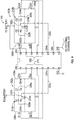
- FIG. 9 is a schematic diagram of an electrical circuit 300 used to provide the current to the windings 234a, 234b.
- the electrical circuit 300 may also be used in combination with the external controller (not illustrated) to determine the position of both of the first gate member 180 and the second gate member 182.
- the electrical circuit 300 includes two H bridges 302a, 302b and a microcontroller 304 in communication with both of the H bridges 302a, 302b.
- the electrical circuit 300 may be completely located upon one of the circuit boards 250a, 250b, and the remaining one of the circuit boards 250a, 250b is merely used for mechanical support of the housing 102.
- a portion of the electrical circuit 300 may be located on both of the circuit boards 250a, 250b, and a connector (not illustrated) may be used to electrically connect both of the circuit boards 250a, 250b together.
- each H bridge 302a, 302b may include four switches.
- the H bridge 302a includes switches S1, S2, S3, S4 and the H bridge 302b includes four switches S1', S2', S3', S4'.
- the switches are each metal-oxide-semiconductor field-effect transistors (MOSFETs), however it is to be appreciated that other types of switches, or even mechanical switches may be used as well.
- MOSFETs metal-oxide-semiconductor field-effect transistors
- Each of the switches may be electrically connected to an output or pin 310 of the microcontroller 304.
- Each H bridge 302a, 302b may also include a resistor R a , R b that is electrically connected to a capacitor C a , C b in series with one another to form a corresponding series circuit 312a, 312b.
- a first end 320a, 320b of the series circuit 312a, 312b may be connected to a first end 322a, 322b of the winding 234a, 234b, and a second end 324a, 324b of the series circuit 312a, 312b may be connected to a second end 326a, 326b of the winding 234a, 234b.
- a sense line 330a, 330b may electrically connect a junction 332a, 332b located between the resistor R a , R b and the capacitor C a , C b to corresponding sense pins 334a, 334b of the microcontroller 304.
- the microcontroller 304 may refer to, be part of, or include an electronic circuit, a combinational logic circuit, a field programmable gate array (FPGA), a processor (shared, dedicated, or group) that executes code, other suitable components that provide the described functionality, or a combination of some or all of the above, such as in a system-on-chip.
- the term module may include memory (shared, dedicated, or group) that stores code executed by the processor.
- code as used above, may include software, firmware, microcode, or assembly code and may refer to programs, routines, functions, classes, or objects. It is to be appreciated that while FIG. 9 illustrates the H bridges 302a, 302b and the microcontroller 304 as separate components, in another embodiment the H bridges 302a, 302b and the microcontroller 304 could be an integrated component.
- the microcontroller 304 may energize the respective pins 310 in order to activate the switches S1 and S4 (which are located on alternating legs 338a of the H bridge 302a) to induce a current across the winding 234a of the solenoid assembly 142a, thereby inducing the first magnetic field within the core 230a of the solenoid 142a.
- the first magnetic field magnetically attracts the gate members 180, 182 of the gate assembly 146.
- the microcontroller 304 simultaneously energizes the respective pins 310 in order to activate the switches S2' and S3' (which are located on alternating legs 338b of the H bridge 302b) to induce a current across the winding 234a of the solenoid assembly 142a, thereby inducing the second magnetic field within the core 230b of the solenoid 142b.
- the first magnetic field magnetically repels the gate members 180, 182 of the gate assembly 146.
- the gate assembly 146 is actuated into the open position.
- the microcontroller 304 may also energize the respective pins 310 in order to activate the switches S2, S3, S1', S4' as well in order to actuate the gate assembly 146 into the closed position.
- the circuit boards 250a, 250b may include circuitry for activating the solenoid assemblies 142a, 142b from either the open position or the closed position by activating one of the first and second solenoid assemblies 142a, 142b to magnetically attract the gate members 180, 182, while simultaneously activating the remaining solenoid assembly 142a, 142b to magnetically repulse the gate members 180, 182.
- the microcontroller 304 may also include an input 340 for receiving power, such as battery voltage.
- the microcontroller 304 may also be connected to ground through pin 342.
- the microcontroller 304 may also send and receive communication from the external controller (not illustrated) through pins 344, 346.
- the external control may be, for example, an ECM.
- the external controller may send a signal to the microcontroller 304 requesting a current position of the gate assembly 146 with respect to the core 230a, and is explained in greater detail below. Referring to FIGS.
- the microcontroller 304 may generate a time varying voltage over a predetermined period of time across both the windings 234a, 234b through both of the H bridges 302a, 302b. Specifically, the microcontroller 304 may alternate the time varying voltage to the alternating legs 338a, 338b of the H-bridges 302a, 302b in order to energize and de-energize both of the windings 234a, 234b.
- the time varying voltage may be square wave voltage having a fixed frequency (e.g., 20 kHz).
- a fixed frequency e.g. 20 kHz.
- the inductance of the winding 234a, the resistor R a , and the capacitor C a may cooperate together to create a circuit that oscillates in response to an excitation created by the square voltage.
- the value of the inductance of the windings 234a, 234b is not fixed, and will vary based on the location of the gate members 180, 182.
- the inductance of the windings 234a, 234b will increase if the gate members 180, 182 are near, and will decrease if the gate members 180, 182 are father away.
- the time varying voltage may include a variety of values, however a peak-to-peak voltage of at least two volts may be required.
- the microcontroller 304 may also monitor the sense lines 330a, 330b. Specifically, the microcontroller 304 may monitor the sense lines 330a, 330b to determine an amplitude of oscillation of the inductance of the windings 234a, 234b. As explained above, the inductance of the windings 234a, 234b is not fixed, and will vary based on the location of the gate members 180, 182. Specifically, a largest amplitude of oscillation is indicative of the location of the gate members 180, 182 relative to the windings 234a, 234b.
- a sweeping frequency may be applied to both the windings 234a, 234b.
- the sweeping frequency may range from a value below a resonant frequency of the inductance of the winding 234a, the resistor R a , and the capacitor C a (or the winding 234b, the resistor R b , and the capacitor C b ) to a value above the resonant frequency, and may be an increasing range of frequencies or a decreasing range of frequencies.
- the microcontroller 304 may also monitor the sense lines 330a, 330b.
- the microcontroller 304 may monitor the sense lines 330a, 330b to determine a peak voltage amplitude of the windings 234a, 234b.
- the peak voltage amplitude is correlated to the distance of the gates 180, 182 relative to the windings 234a, 234b.
- the microcontroller 304 may send a signal over pin 346 to the external control indicative of the distance of the gates 180, 182 relative to the windings 234a, 234b.
- the external controller may receive the singal indicate of the position of the gates 180, 182, and determines a different position of the gate assembly 146 based on the current position of the gates 180, 182. For example, if the gate assembly 146 is in the open position, the external controller may determine that the different position is the closed position.
- the device 100 as described above and illustrated in FIGS. 1-9 is a solanoid actuated control valve that may be used in a variety of applications, such as automotive applications, and may control the flow of fluids such as air, coolant, fuel, or oil. It is to be understood that the valves currently available may be spring biased to a default position, and require the application of current to a solenoid coil to move the valve to an "on" position. As long as the valve is on, power is being consumed. The disclosed valve assembly does not require the continuous application of power to hold the disclosed gate assembly in either the open or closed position. Furthermore, the disclosed device also provides an approach for determining the current position of the valve electronically.
Description
- This application relates to shut-off valves having on and off positions, and more particularly to magnetically actuated solenoid valves for use in an internal combustion engine.
- In current actuators, the on/off operation in a pneumatic device is achieved with an electric solenoid valve. Vacuum force is applied to the actuator only when the solenoid is "on" and only when the vacuum force is high enough to move the actuator the full length of its travel. Alternately, without a solenoid controlling the actuator's exposure to vacuum, an actuator exposed to vacuum force under all conditions will "float" between the on position and the off position. Floating is undesirable, inefficient, and provides poor control of the device attached to the actuator.
- Often, solenoid actuated valves are spring biased to a default condition and require the application of current to a coil to move the valve to the energized position. However, as long as the valve is in the on-state, then it is to be appreciated that power is consumed. Thus, there is a need in the art for energy efficient actuators that are effective at controlling an electric solenoid's on-state, while reducing the amount of power consumed.
- Examples of known solenoid valves are disclosed by
US2015/162155A1 ,US5982605A ,WO 2012/089962 A1 ,US6049264A ,US2011/196541 A1 ,EP2885965A1 ,US2007/227478A1 ,US2012/161049A1 ,US5490031A ,US2007/053133A1 ,US2015/128573A1 ,US5781399A ,US2004/113731A1 . - Herein actuators are described for the control of valves having on-off functionality that consume less power. The actuators disclosed herein are held in either the open state or the closed state without requiring the continuous consumption of power because the actuators utilize the application of electric current through a solenoid to move a valve to a desired position and once moved thereto the residual magnetism will maintain the valve in the desired position. Additionally, the state of the valve (in the open position or in the closed position) is determined electronically by a control circuit based on changes in the inductance of the actuation coils (a first coil at one end and a second coil at the opposing end of the gate assembly) due to the location of the gate.
- In one aspect, a latching solenoid gate valve is disclosed, and includes a housing defining a conduit having a flow path therethrough and a cavity separating the conduit into a first section and a second section. The latching solenoid assembly also includes a gate assembly enclosed within the cavity of the housing and a first solenoid assembly and a second solenoid assembly seated within the cavity with the gate assembly linearly translatable therebetween. The gate assembly includes a first gate member comprising magnetizable material and defining an opening therethrough. The first gate member is linearly movable within the cavity between an open position with the opening aligned with the conduit and a closed position with the opening out of alignment with the conduit. The first gate member is moved linearly from either the open position or the closed position by activating one of the first and second solenoid assemblies to magnetically attract the first gate member thereto while simultaneously activating the other of the first and second selenoid assemblies to magnetically repulse the first gate member.
- In another aspect, a method for linearly translating a gate assembly within a latching solenoid gate valve is disclosed. The method includes providing a latching solenoid gate valve including a housing defining a conduit having a flow path therethrough and a cavity separating the conduit into a first section and a second section. The method also includes providing a gate assembly comprising a first gate member comprising magnetizable material and defining an opening therethrough. The first gate member is linearly movable within the cavity between an open position with the opening aligned with the conduit and a closed position with the opening out of alignment with the conduit. The method also includes providing a first solenoid assembly and a second solenoid assembly seated within the cavity with the gate assembly linearly translatable therebetween. The method further includes providing a microcontroller electrically connected to a first H bridge for the first solenoid assembly with a first winding as a load of the first H bridge and electrically connected to a second H bridge for the second solenoid assembly with a second winding as a load of the second H bridge. The method also includes receiving, by the microcontroller, a signal requesting a position of the gate assembly. The method also includes sending, from the microcontroller, a time varying voltage over a predetermined period of time across the first winding in the first solenoid assembly and across the second winding in the second solenoid assembly through both of the first and second H bridges while alternating a flow thereof through alternate legs of each of the first and second H bridges to energize and de-energize both of the first and second windings. Finally, the method includes monitoring the first and second sense lines to determine an amplitude of oscillation of each. The amplitude of oscillation is correlated to a distance of the first gate member from each of the first and second windings and a largest amplitude of oscillation of either the first or the second sense line indicates the position of the gate assembly.
- In yet another embodiment, a method for linearly translating a gate assembly within a latching solenoid gate valve is disclosed. The method includes providing a latching solenoid gate valve including a gate assembly comprising a housing defining a conduit having a flow path therethrough and a cavity separating the conduit into a first section and a second section. The method also includes providing first gate member comprising magnetizable material and defining an opening therethrough. The first gate member is linearly movable within the cavity between an open position with the opening aligned with the conduit and a closed position with the opening out of alignment with the conduit. The method also includes providing a first solenoid assembly and a second solenoid assembly seated within the cavity with the gate assembly linearly translatable therebetween. The method further includes providing a microcontroller electrically connected to a first H bridge for the first solenoid assembly with a first winding as a load of the first H bridge and electrically connected to a second H bridge for the second solenoid assembly with a second winding as a load of the second H bridge. The method also includes receiving in the microcontroller a signal requesting the position of the gate assembly. The method further includes sending, from the microcontroller, frequencies to both the first winding in the first solenoid assembly and the second winding in the second solenoid assembly over an increasing or decreasing range of frequencies. Finally, the method includes monitoring the first and second sense lines to determine the peak voltage amplitude of each. The peak voltage amplitude has a correlation to the distance of the gate from each of the first and second windings and the largest peak of either the first or the second sense line indicates the position of the gate assembly.
-
-
FIG. 1 is a front perspective view of one embodiment of a latching solenoid gate valve. -
FIG. 2 is a front, exploded perspective view of latching solenoid gate valve ofFIG. 1 . -
FIG. 3 is a longitudinal, cross-sectional view of the latching solenoid gate valve ofFIG. 2 in an assembled state. -
FIG. 4 is a side perspective view of the sprung gate of the latching solenoid gate valve ofFIGS. 1-3 . -
FIG. 5 is an exploded view of the sprung gate of the latching solenoid gate valve ofFIGS. 1-3 . -
FIG. 6 is an exploded view of the sprung gate and the latching solenoids ofFIGS. 1-3 . -
FIG. 7 is a side perspective view of a second embodiment of a sprung gate for a latching solenoid gate valve. -
FIG. 8 is a cross-sectional, exploded perspective view of latching solenoid gate valve ofFIG. 1 . -
FIG. 9 is an electrical schematic diagram of a circuit that drives the solenoid assemblies and also senses the position of the gate assembly in the latching solenoid gate valve ofFIG. 1 . - The following detailed description will illustrate the general principles of the invention, examples of which are additionally illustrated in the accompanying drawings. In the drawings, like reference numbers indicate identical or functionally similar elements.
- As used herein "fluid" means any liquid, suspension, colloid, gas, plasma, or combinations thereof.
-
FIGS. 1-2 illustrate an embodiment of a latchingsolenoid gate valve 100, in one embodiment, for use in an internal combustion engine. The latchingsolenoid gate valve 100 includes ahousing 102 and aconduit 104 for transporting or allowing the flow of fluid therethrough. Thehousing 102 defines defines a cavity 138 (FIG. 2 ) therein that separates theconduit 104 into afirst conduit portion 106 and asecond section 108. Thehousing 102 may include a first section A and a second section B that are mateable together to define thecavity 138. In one embodiment, the first section A and the second section B of thehousing 102 may be plastic injection molded components fixedly mated together using a plastic welding process. - The
first conduit portion 106 may be sealingly engaged with a hose or a tube (not illustrated), where a generally fluid-tight seal may be created between thesealing features 118 of thefirst conduit portion 106 and the tube. One or both of the first andsecond conduit portions first section 110, 110' that may includesealing features 118, 118' on the exterior surface thereof. One or both of the first andsecond conduit portions second section 120, 120', respectively, between thefirst sections 110, 110' and theouter surface 112, 112' of thehousing 102. In one embodiment, thefirst section 110 of thefirst conduit portion 106 may include a generally circular cross-section and thesecond section 120 of thefirst conduit portion 106 may include a generally rectangular cross-section. Thesecond conduit portion 108 may include a similar configuration. Although a circular cross-section and a rectangular cross-section are discussed, theconduits - Referring to
FIGS. 2 and3 , anopening 114 of the housing A is in fluid communication with thefirst conduit portion 106. Theopening 114 of the housing A is located along aninner surface 116 of the first section A of thehousing 102. Anopening 124 of the housing B is in fluid communication with thesecond conduit potion 108, and is located along aninner surface 126 of the second section B of thehousing 102. Theopening 114 of the housing A and theopening 124 of the housing B are aligned with one another such that both theopenings conduit 104. Afirst solenoid assembly 142a and asecond solenoid assembly 142b are seated within thecavity 138 defined by the first section A and the second section B of thehousing 102. Agate assembly 146 is linearly translatable between thefirst solenoid assembly 142a and thesecond solenoid assembly 142b. - The
gate assembly 146 may translate in a linear direction between an open position and a closed position. In the open position, which is seen inFIG. 3 , a fluid flow opening 191 of thegate assembly 146 may be aligned with theconduit 104, and in particular thegate assembly 146 is aligned with theopenings first conduit portion 106 through thegate assembly 146, and into thesecond conduit portion 108. When in the closed position, the fluid flow opening 191 is out of alignment with theconduit 104, thereby blocking the flow of fluid though thegate assembly 146 and to thesecond conduit portion 108. As seen inFIG. 3 , thegate assembly 146 may be translated up and down in a linear direction through a length of travel L between the open position and the closed position. The length of travel L may be measured between alower surface 176 of thegate assembly 146 and thesecond solenoid assembly 142b when thegate assembly 146 is in a first position (i.e., thegate assembly 146 is opened). Alternatively, the length of travel L may be measured between anupper surface 174 of thegate assembly 146 and thefirst solenoid assembly 142a, when thegate assembly 146 is in a second position (i.e., thegate assembly 146 is closed). -
FIG. 4 is a side perspective view of thegate assembly 146,FIG. 5 is an exploded view of thegate assembly 146,FIG. 6 is an exploded view of thegate assembly 146 as well as both thesolenoid assemblies FIG. 7 is a perspective view of thegate assembly 146 as well as twopermanent magnets FIGS. 4-6 , thegate assembly 146 includes afirst gate member 180 defining anopening 194 therethrough, and asecond gate member 182 defining at least afirst opening 195 therethrough aligned with theopening 194 in thefirst gate member 180. Theopenings fluid flow opening 191. Thegate assembly 146 may also include an endlesselastic band 184 sandwiched or located between the first andsecond gate members - The first and
second gate members second gate members second gate members second gate members FIG. 7 , thegate assembly 146 includes a firstpermanent magnet 202 disposed along theupper surface 174 of thegate assembly 146 and a secondpermanent magnet 204 disposed along thelower surface 176 of thegate assembly 146. - Referring to
FIGS. 2 and6 , thegate assembly 146 is positioned between the first (upper, in the drawing as oriented relative to the page)solenoid assembly 142a and the second (lower, in the drawing as oriented relative to the page)solenoid assembly 142b. Theupper surface 174 and thelower surface 176 of thegate assembly 146 are both defined collectively by thefirst gate member 180 and thesecond gate member 182 when in an assembled state (illustrated inFIG. 3 ). As seen inFIGS. 4 and 5 , thefirst gate member 180 and thesecond gate member 182 interlock with one another. In this exemplary embodiment, aside surface 190 of thefirst gate member 180 may define arecess 192. Thesecond gate member 182 includes aside surface 194 that defines atab 196. Thetab 196 of thesecond gate member 182 may be received by therecess 192 of thefirst gate member 180. Those skilled in the art will readily appreciate that whileFIGS. 4-5 only illustrate one side of thefirst gate member 180 and thesecond gate member 182, a similar configuration may be included along the opposing sides of thegate members - Referring to
FIGS. 4 and 5 , the endlesselastic band 184 is located between the first andsecond gate members elastic band 184 defines anopening 186 that is aligned with theopening 194 in thefirst gate member 180 andopening 195 in thesecond gate member 182. With the endlesselastic band 184 sandwiched between the first andsecond gate member gate assembly 146 through the length of travel L (shown inFIG. 3 ). The endlesselastic band 184 may be constructed of a compliant material such as, for example, rubber. The endlesselastic band 184 may act as a biasing member or compliant spring in order to bias thefirst gate member 180 and thesecond gate member 182 apart from one another. As seen inFIG. 4 , when thegate assembly 146 is assembled together, the endlesselastic band 184 may be contained by a cavity orrecess 198 defined by both of thefirst gate member 180 and thesecond gate member 182. - Referring to
FIG. 5 , the endlesselastic band 184 includes afirst lip 210 and asecond lip 212. Thefirst lip 210 of theelastic band 184 may seal against aninner surface 214 of thefirst gate member 180, and thesecond lip 212 may seal against aninner surface 216 of thesecond gate member 182. It should be appreciated that the seal created between the endlesselastic band 184 and thefirst gate member 180 and thesecond gate member 182 may reduce or prevent fluid leakage into the housing 102 (FIGS. 1-2 ). It should also be appreciated that the illustration of thegate assembly 146 should not be limiting in nature. For example, in another approach a gate assembly may be used that includes the configuration as shown inFIG. 7 of commonly ownedU.S. Patent Application No. 14/565,814 filed on December 10, 2014 - Referring to
FIGS. 2 and4-5 , thefirst gate member 180 may define afront gate surface 218. When thegate assembly 146 is in the closed position, thefront gate surface 218 of thefirst gate member 180 may block or obstruct the flow of fluid into the fluid flow opening 191 of thegate assembly 146. However, when thegate assembly 146 is in the open position, which is seen inFIG. 3 , fluid may flow from thefirst conduit portion 106 of the housing A, through the fluid flow opening 191 defined by thegate assembly 146, and into thesecond conduit portion 108 of the second housing B. - Referring to
FIGS. 2 and6 , both thefirst solenoid assembly 142a and thesecond solenoid assembly 142b each include arespective cores cores FIG. 4 , thecores cores legs 232 of equal size, the legs of each core 230a, 230b may be of different size as well. - Continuing to refer to both
FIGS. 2 and6 ,bobbins center leg 232 of each core 230a, 230b. In one embodiment, thebobbins bobbins bobbins main body FIGS. 2 ,6 , and8 , thebobbins aperture respective channels FIG. 8 ). - Corresponding wiring may be wound around the
respective channels windings windings respective apertures bobbins central leg 232 of arespective core bobbins windings windings bobbins corresponding circuit board circuit boards solenoid assemblies - As seen in
FIG. 2 , the second section B of thehousing 102 may includeguides 252 that project outward from aninner wall 254 of the second section B. Theguides 252 may be used to provide guidance and ensure that thegate assembly 146 translates in a linear direction through the length of travel L (shown inFIG. 3 ). The second section B of thehousing 102 may include a second set ofguides 256 that also project outward from aninner wall 254 of the second section B. Theguides 256 may be used to position thecircuit board housing 102. In addition to controlling thesolenoid assemblies circuit boards housing 102 in order to provide mechanical support and stiffening. It is to be appreciated that the first housing A also includes similar features along an inner wall as well, however these features are not visible inFIG. 2 . - Referring to both
FIGS. 1 and2 , it should be appreciated that thehousing 102 may also include electrical connectors (not illustrated) that are electrically connected to a corresponding one of thecircuit boards circuit boards - The
gate assembly 146 may be normally seated in a starting position. The starting position may be either the closed position or the open position (shown inFIG. 3 ). Thegate assembly 146 remains seated in the starting position until a threshold force is applied to thegate assembly 146. The threshold force is explained in greater detail below, and is created by opposing magnetic fields induced within thecores gate assembly 146 from the starting position, and causes thegate assembly 146 to move into a second position. The second position is opposite from the normally seated position. For example, if the normally seated position is the open position (shown inFIG. 3 ), then the second position would be the closed position. It is to be appreciated that thegate assembly 146 is biased in either the open or the closed position due to residual magnetism within thefirst gate member 180 and thesecond gate member 182 after the opposing magnetic fields have been removed. - Referring to
FIGS. 2-3 , when electrical current is applied to the winding 234a, a first magnetic field is induced within thecore 230a of thesolenoid 142a. The first magnetic field may be based on the amount of electrical current provided to the winding 234a. Specifically, a first amount of electrical current may be applied to the winding 234a, which in turn creates the first magnetic field. The first magnetic field may attract the residually magnetizedfirst gate member 180 andsecond gate member 182. In other words, the first magnetic field may urge thegate member 180 andsecond gate member 182 in a direction towards thecore 230a, and into the open position as seen inFIG. 3 . - At the same time the first amount of electrical current is applied to the winding 234a, a second, opposite amount of electrical current is applied to the winding 234b in order to induce a second magnetic field within the core 230b of the
solenoid 142b. It is to be appreciated that the second, opposite magnetic field is generated to repel the residually magnetizedfirst gate member 180 andsecond gate member 182. In other words, the second magnetic field may urge thefirst gate member 180 and thesecond gate member 182 in a direction away from the core 230b, and towards thecore 230a. The first magnetic field induced by thecore 230a and the second, opposite magnetic field induced by thecore 230b cooperate together in order to create the threshold force. The threshold force is of sufficient magnitude to urge thegate assembly 146 to translate in the linear direction through the length of travel L and into the second position (i.e., into the open position as seen inFIG. 3 ). Although actuating thegate assembly 146 into the open position is described, it is to be appreciated that the current supplied to thewindings gate assembly 146 into the closed position as well. -
FIG. 9 is a schematic diagram of anelectrical circuit 300 used to provide the current to thewindings electrical circuit 300 may also be used in combination with the external controller (not illustrated) to determine the position of both of thefirst gate member 180 and thesecond gate member 182. Theelectrical circuit 300 includes twoH bridges 302a, 302b and amicrocontroller 304 in communication with both of the H bridges 302a, 302b. Referring to bothFIGS. 2 and9 , it is to be appreciated that in one embodiment theelectrical circuit 300 may be completely located upon one of thecircuit boards circuit boards housing 102. Alternatively, in another embodiment, a portion of theelectrical circuit 300 may be located on both of thecircuit boards circuit boards - Referring to
FIG. 9 , eachH bridge 302a, 302b may include four switches. Specifically, the H bridge 302a includes switches S1, S2, S3, S4 and theH bridge 302b includes four switches S1', S2', S3', S4'. In the embodiment as shown inFIG. 9 , the switches are each metal-oxide-semiconductor field-effect transistors (MOSFETs), however it is to be appreciated that other types of switches, or even mechanical switches may be used as well. Each of the switches may be electrically connected to an output or pin 310 of themicrocontroller 304. EachH bridge 302a, 302b may also include a resistor Ra, Rb that is electrically connected to a capacitor Ca, Cb in series with one another to form acorresponding series circuit FIG. 9 , afirst end 320a, 320b of theseries circuit first end second end series circuit second end respective windings sense line junction 332a, 332b located between the resistor Ra, Rb and the capacitor Ca, Cb to corresponding sense pins 334a, 334b of themicrocontroller 304. - The
microcontroller 304 may refer to, be part of, or include an electronic circuit, a combinational logic circuit, a field programmable gate array (FPGA), a processor (shared, dedicated, or group) that executes code, other suitable components that provide the described functionality, or a combination of some or all of the above, such as in a system-on-chip. The term module may include memory (shared, dedicated, or group) that stores code executed by the processor. The term code, as used above, may include software, firmware, microcode, or assembly code and may refer to programs, routines, functions, classes, or objects. It is to be appreciated that whileFIG. 9 illustrates the H bridges 302a, 302b and themicrocontroller 304 as separate components, in another embodiment the H bridges 302a, 302b and themicrocontroller 304 could be an integrated component. - Referring to
FIGS. 2-3 and9 , themicrocontroller 304 may energize therespective pins 310 in order to activate the switches S1 and S4 (which are located on alternatinglegs 338a of the H bridge 302a) to induce a current across the winding 234a of thesolenoid assembly 142a, thereby inducing the first magnetic field within thecore 230a of thesolenoid 142a. The first magnetic field magnetically attracts thegate members gate assembly 146. Themicrocontroller 304 simultaneously energizes therespective pins 310 in order to activate the switches S2' and S3' (which are located on alternatinglegs 338b of theH bridge 302b) to induce a current across the winding 234a of thesolenoid assembly 142a, thereby inducing the second magnetic field within the core 230b of thesolenoid 142b. The first magnetic field magnetically repels thegate members gate assembly 146. Thus, thegate assembly 146 is actuated into the open position. - It is to be appreciated that while the switches S1, S4, S2', S3' are described as being activated, it is to be appreciated that the
microcontroller 304 may also energize therespective pins 310 in order to activate the switches S2, S3, S1', S4' as well in order to actuate thegate assembly 146 into the closed position. Thus, it is to be appreciated that thecircuit boards solenoid assemblies second solenoid assemblies gate members solenoid assembly gate members - Referring to
FIG. 9 , themicrocontroller 304 may also include aninput 340 for receiving power, such as battery voltage. Themicrocontroller 304 may also be connected to ground throughpin 342. Furthermore, themicrocontroller 304 may also send and receive communication from the external controller (not illustrated) throughpins microcontroller 304 requesting a current position of thegate assembly 146 with respect to thecore 230a, and is explained in greater detail below. Referring toFIGS. 2-3 and9 , in response to receiving a signal from the external controller requesting the current position of thegate assembly 146 frompin 344, themicrocontroller 304 may generate a time varying voltage over a predetermined period of time across both thewindings microcontroller 304 may alternate the time varying voltage to the alternatinglegs bridges 302a, 302b in order to energize and de-energize both of thewindings - In one embodiment, the time varying voltage may be square wave voltage having a fixed frequency (e.g., 20 kHz). Specifically, it should be appreciated that the inductance of the winding 234a, the resistor Ra, and the capacitor Ca (or the winding 234b, the resistor Rb, and the capacitor Cb) may cooperate together to create a circuit that oscillates in response to an excitation created by the square voltage. The value of the inductance of the
windings gate members windings gate members gate members - As the
microcontroller 304 generates the time varying voltage, themicrocontroller 304 may also monitor thesense lines microcontroller 304 may monitor thesense lines windings windings gate members gate members windings - Instead of a time varying voltage, in another embodiment a sweeping frequency may be applied to both the
windings microcontroller 304 generates the sweeping frequency, themicrocontroller 304 may also monitor thesense lines microcontroller 304 may monitor thesense lines windings gates windings - Referring to
FIGS. 2-3 and9 , themicrocontroller 304 may send a signal overpin 346 to the external control indicative of the distance of thegates windings gates gate assembly 146 based on the current position of thegates gate assembly 146 is in the open position, the external controller may determine that the different position is the closed position. - The
device 100 as described above and illustrated inFIGS. 1-9 is a solanoid actuated control valve that may be used in a variety of applications, such as automotive applications, and may control the flow of fluids such as air, coolant, fuel, or oil. It is to be understood that the valves currently available may be spring biased to a default position, and require the application of current to a solenoid coil to move the valve to an "on" position. As long as the valve is on, power is being consumed. The disclosed valve assembly does not require the continuous application of power to hold the disclosed gate assembly in either the open or closed position. Furthermore, the disclosed device also provides an approach for determining the current position of the valve electronically. - Having described the invention in detail and by reference to preferred embodiments thereof, it will be apparent that modifications and variations are possible without departing from the scope of the invention as defined in the appended set of claims.
Claims (18)
- A latching solenoid gate valve (100) comprising:a housing(102) defining a conduit(104) having a flow path therethrough and a cavity(138) separating the conduit(104) into a first section(106) and a second section(108);a gate assembly(146) enclosed within the cavity(138) of the housing(102), the gate assembly(146) comprising:
a first gate member(180) comprising magnetizable material and defining an opening therethrough, the first gate member(180) being linearly movable within the cavity(138) between an open position with the opening aligned with the conduit(104) and a closed position with the opening out of alignment with the conduit(104);a first solenoid assembly(142a) and a second solenoid assembly(142b) seated within the cavity(138) with the gate assembly(146) linearly translatable therebetween;wherein the first gate member(180) is moved linearly from either the open position or the closed position by activating one of the first and second solenoid assemblies(142a, 142b) to magnetically attract the first gate member(180) thereto while simultaneously activating the other of the first and second solenoid assemblies(142a, 142b) to magnetically repulse the first gate member(180);characterized in that each of the first solenoid assembly(142a) and the second solenoid assembly(142b) comprises a circuit board (250a, 250b) and a winding (234a, 234b) electrically connected to the circuit board(250a, 250b); andwherein the circuit board(250a, 250b) comprises a microcontroller(304) electrically connected to a first H bridge(302a) for the first solenoid assembly(142a) with the winding of the first solenoid assembly(142a) as a load of the first H bridge(302a), and wherein the microcontroller(304) is electrically connected to a second H bridge(302b) for the second solenoid(142b) assembly with the winding of the second solenoid assembly(142b) as a load of the second H bridge(302b); wherein the first and second H bridges(302a, 302b) are electrically connected to the microcontroller(304) to each energize the winding in the first solenoid assembly(142a) and the second solenoid assembly(142b), respectively, with current in either direction. - The latching solenoid gate valve of claim 1, wherein each of the first solenoid assembly and the second solenoid assembly comprises a core, wherein the core is a generally E-shaped core(230a, 230b).
- The latching solenoid gate valve of claim 1, wherein the first H bridge(302a) comprises a first resistor (Ra)and a first capacitor (Ca) electrically connected in a first series circuit (312a)with one end (320a) of the first series circuit(312a) connected to a first end(322a) of the winding(234a) of the first solenoid assembly(142a) and the other end(324a) of the first series circuit(312a) connected to a second end(326a) of the winding(234a) of the first solenoid(142a) assembly, and a first sense line(330a) electrically connected at a first junction (332a) between the first resistor (Ra) and the first capacitor(Ca) is electrically coupled to the microcontroller(304).
- The latching solenoid gate valve of claim 3, wherein the second H bridge comprises a second resistor (Rb) and a second capacitor (Cb) electrically connected in a second series circuit (312b) with one end(320b) of the second series circuit(312b) connected to a first end(322b) of the winding of the second solenoid assembly(142b) and the other end(324b) of the second series circuit(312b) connected to a second end(326b) of the winding(234b) of the second solenoid assembly(142b) and a second sense line(330b) electrically connected at a second junction (332b) between the second resistor(Rb) and the second capacitor(Cb) is electrically coupled to the microcontroller(304) .
- The latching solenoid gate valve of claim 3, wherein the gate assembly(146) further comprises an endless elastic band(184) sandwiched between the first gate member(180) and a second gate member(182) with a second opening defined by the endless elastic band(184) aligned with the opening in the first gate member(180), wherein the endless elastic band(184) is linearly translatable together with the first and second gate members(180, 182) within the cavity(138).
- The latching solenoid gate valve of claim 5, wherein the housing(102) includes guides (252, 256) protruding within the cavity(138) between which the gate assembly(146) is seated.
- The latching solenoid gate valve of claim 1, wherein the housing(102) further comprises an electrical connector protruding therefrom that electrically connects the circuit board(250a, 250b) to an external controller.
- The latching solenoid gate valve of claim 1, wherein the gate assembly(146) further comprises a second gate member(182) having a second opening therethrough, wherein both the first gate member(180) and the second gate member(182) are linearly translatable together within the cavity(138).
- The latching solenoid gate valve of claim 8, wherein the first gate member(180) and the second gate member(182) are constructed of a magnetizable material.
- The latching solenoid gate valve of claim 8, wherein the gate assembly(146) includes a first permanent magnet disposed along an upper surface of the gate assembly(146) and a second permanent magnet disposed along a lower surface of the gate assembly(146).
- A method for linearly translating a gate assembly (146) within a latching solenoid gate valve, the method comprising;
providing a latching solenoid gate valve(100) according to claim 1 ;receiving, by each microcontroller(304), a signal requesting a position of the gate assembly(146);
sending, from each microcontroller, a time varying voltage over a predetermined period of time across the winding in the first solenoid assembly(142a) and across the winding in the second solenoid assembly(142b) through both of the first and second H bridges(302a, 302b) while alternating a current thereof through alternate legs of each of the first and second H bridges(302a, 302b) to energize and de-energize the winding in the first solenoid assembly and the winding in the second solenoid assembly;
monitoring an amplitude of oscillation or peak voltage amplitude of each of a first sense line (330a) between a junction (332a) located between a resistor (Ra) and a capacitor (Ca) to a corresponding sense pin (334a) of the microcontroller(304) for the first solenoid assembly and of a second sense line (330b) between a junction (332b) located between a resistor (Rb) and a capacitor (Cb) to a corresponding sense pin (334b) of the microcontroller(304) for the second solenoid assembly;
wherein the amplitude of oscillation or the peak voltage amplitude is correlated to a distance of the first gate member(180) from the respective winding of the first and second solenoid assembly and a largest amplitude of oscillation or largest peak voltage amplitude of either of the first or the second sense line indicates the position of the gate assembly(146). - The method of claim 11, further comprising sending a signal from the microcontroller (304) indicating the position of the gate assembly (146) based on the amplitude of oscillation.
- The method of claim 12, further comprising:providing an external controller electrically connected to the microcontroller (304);receiving at the external controller the signal from the microcontroller (304).
- The method of claim 13, comprising signaling from the external controller to the microcontroller(304), based on the signal indicating the position of the gate assembly(146), to activate appropriate legs of both of the first and second H bridges(302a, 302b) to have one of the first and second solenoid assemblies(142a, 142b) magnetically attract the first gate member(180) thereto while the other of the first and second solenoid assemblies(142a, 142b) magnetically repulses the first gate member(180) thereby linearly translating the gate assembly(146) to a different position.
- The method of claim 11 further comprising;
sending, from the microcontroller(304), frequencies to both the first winding in the first solenoid assembly(142a) and the second winding in the second solenoid assembly(142b) over an increasing or decreasing range of frequencies;
wherein monitoring of the first and second sense lines is to determine the peak voltage amplitude of each. - The method of claim 15, further comprising sending a signal from the microcontroller(304) indicating the position of the gate assembly(146) based on the largest peak amplitude.
- The method of claim 16, further comprising:providing an external controller electrically connected to the microcontroller(304); andreceiving at the external controller the signal from the microcontroller(304).
- The method of claim 17, comprising signaling from the external controller to the microcontroller(304), based on the signal indicating the position of the gate assembly, to activate appropriate legs of both of the first and second H bridges(302a, 302b) to have one of the first and second solenoid assemblies(142a, 142b) magnetically attract the first gate member(180) thereto while the other of the first and second selenoid assemblies (142a, 142b) magnetically repulses the first gate member(180) thereby linearly translating the gate assembly(146) to a different position.
Applications Claiming Priority (2)
| Application Number | Priority Date | Filing Date | Title |
|---|---|---|---|
| US14/818,851 US9599246B2 (en) | 2015-08-05 | 2015-08-05 | Magnetically actuated shut-off valve |
| PCT/US2016/045565 WO2017024139A1 (en) | 2015-08-05 | 2016-08-04 | Magnetically actuated shut-off valve |
Publications (3)
| Publication Number | Publication Date |
|---|---|
| EP3332415A1 EP3332415A1 (en) | 2018-06-13 |
| EP3332415A4 EP3332415A4 (en) | 2019-03-27 |
| EP3332415B1 true EP3332415B1 (en) | 2020-07-15 |
Family
ID=57943690
Family Applications (1)
| Application Number | Title | Priority Date | Filing Date |
|---|---|---|---|
| EP16833875.4A Active EP3332415B1 (en) | 2015-08-05 | 2016-08-04 | Magnetically actuated shut-off valve |
Country Status (7)
| Country | Link |
|---|---|
| US (2) | US9599246B2 (en) |
| EP (1) | EP3332415B1 (en) |
| JP (1) | JP6782764B2 (en) |
| KR (1) | KR102411782B1 (en) |
| CN (1) | CN107851541B (en) |
| BR (1) | BR112018002317B1 (en) |
| WO (1) | WO2017024139A1 (en) |
Families Citing this family (8)
| Publication number | Priority date | Publication date | Assignee | Title |
|---|---|---|---|---|
| USD780296S1 (en) * | 2015-07-17 | 2017-02-28 | Dayco Ip Holdings, Llc | Actuated valve |
| SG10201602833VA (en) * | 2016-04-11 | 2017-11-29 | Abrasive Eng Pte Ltd | Magnetic Valve for Shot Peening |
| US10473067B1 (en) * | 2018-05-25 | 2019-11-12 | Caterpillar Inc. | Air shutoff valve |
| DE102018120858A1 (en) * | 2018-08-27 | 2020-02-27 | Schaeffler Technologies AG & Co. KG | Control valve for a thermal management module |
| JP7127429B2 (en) * | 2018-08-28 | 2022-08-30 | トヨタ自動車株式会社 | electric valve system |
| US11844488B2 (en) * | 2021-06-30 | 2023-12-19 | Oneida Air Systems, Inc. | Dust collection system blast gate valve |
| CN113770062B (en) * | 2021-09-07 | 2023-02-28 | 合肥峻茂视觉科技有限公司 | Crawler-type color sorter for marine products |
| CN115163854B (en) * | 2022-07-13 | 2023-04-11 | 长沙市奇俊机电科技有限公司 | Large-traffic gate valve subassembly |
Family Cites Families (140)
| Publication number | Priority date | Publication date | Assignee | Title |
|---|---|---|---|---|
| DE501348C (en) | 1927-04-09 | 1930-07-01 | Wilh Strube G M B H | Gate valve |
| US2204142A (en) | 1937-12-13 | 1940-06-11 | Macclatchie Mfg Company | Gate valve |
| US2306490A (en) | 1939-09-11 | 1942-12-29 | Reed Roller Bit Co | Valve |
| US2740962A (en) | 1950-01-05 | 1956-04-03 | Sperry Rand Corp | Three axis tracking system |
| US2816730A (en) | 1951-04-20 | 1957-12-17 | Rabas Eduard | Shut-off valve |
| US2705610A (en) | 1951-05-05 | 1955-04-05 | Crane Co | Conduit valve |
| US2913220A (en) | 1955-06-20 | 1959-11-17 | Martin L Cover | Valve structure and method of installation |
| US2750962A (en) | 1955-06-28 | 1956-06-19 | Morton A Kreitchman | Solenoid operated valve structure |
| US2835468A (en) * | 1956-02-13 | 1958-05-20 | Clary Corp | Valve construction |
| US2953346A (en) | 1956-02-29 | 1960-09-20 | Hochdruck Dichtungs Fabrik Sch | Gate valves |
| US3069131A (en) | 1959-10-09 | 1962-12-18 | Marvin H Grove | Valve construction |
| US3113757A (en) | 1961-01-18 | 1963-12-10 | Nixon Phillip | Solenoid-operated gate valve |
| US3203447A (en) | 1963-10-09 | 1965-08-31 | Skinner Prec Ind Inc | Magnetically operated valve |
| US3379214A (en) | 1965-01-15 | 1968-04-23 | Skinner Prec Ind Inc | Permanent magnet valve assembly |
| US3478771A (en) | 1967-09-15 | 1969-11-18 | Amca Pharm Lab Ltd | Sectional body gate valve with seat scraping means |
| US3534307A (en) | 1969-02-13 | 1970-10-13 | Westinghouse Electric Corp | Electromagnetically or mechanically controlled magnetically-latched relay |
| US3666231A (en) * | 1969-03-10 | 1972-05-30 | Fiat Spa | Sealed valve with electromagnetic action |
| US3635601A (en) | 1970-08-10 | 1972-01-18 | Economics Lab | Fail-safe multiple product aspirator |
| US3768774A (en) | 1971-06-16 | 1973-10-30 | Vetco Offshore Ind Inc | Gate valve with pressure actuated plug seat |
| US3706321A (en) | 1971-09-21 | 1972-12-19 | Acf Ind Inc | Manual override indicator for gate valve |
| GB1411303A (en) | 1973-05-02 | 1975-10-22 | Coplastix Ltd | Fluid flow control valves |
| US3871616A (en) | 1973-12-10 | 1975-03-18 | Julian S Taylor | Gate valve disc |
| US4004258A (en) * | 1974-11-20 | 1977-01-18 | Valcor Engineering Corporation | Position indicating pulse latching solenoid |
| US4010928A (en) | 1974-12-27 | 1977-03-08 | Xomox Corporation | Piston-operated parallel-slide gate valve |
| US4056255A (en) | 1975-05-08 | 1977-11-01 | Lace Donald A | Valve actuator |
| CA1063454A (en) | 1975-10-29 | 1979-10-02 | Blakeway Industries Ltd. | Carburetor for an internal combustion engine |
| US4013090A (en) | 1975-11-10 | 1977-03-22 | Taylor Julian S | Gate valve rotating disc |
| DE2714933C3 (en) | 1977-04-02 | 1981-02-26 | Guenter 5650 Solingen Burgmer | Flat slide |
| US4157169A (en) | 1977-10-12 | 1979-06-05 | Torr Vacuum Products | Fluid operated gate valve for use with vacuum equipment |
| US4146209A (en) | 1977-12-08 | 1979-03-27 | Armco Steel Corporation | Gate valve |
| US4179099A (en) | 1978-07-03 | 1979-12-18 | Petroleum Designers, Inc. | Expanding gate valve |
| US4210308A (en) | 1978-07-24 | 1980-07-01 | Sims James O | Valve |
| US4253487A (en) | 1978-11-13 | 1981-03-03 | Exxon Research & Engineering Co. | Multi-position dual disc slide valve |
| US4385280A (en) | 1979-04-30 | 1983-05-24 | Minnesota Mining And Manufacturing Company | Low reluctance latching magnets |
| US4321652A (en) | 1979-04-30 | 1982-03-23 | Minnesota Mining And Manufacturing Co. | Low voltage transformer relay |
| US4340336A (en) | 1980-03-17 | 1982-07-20 | Hudson Oxygen Therapy Sales Company | Aspirator |
| US4341369A (en) | 1980-04-25 | 1982-07-27 | Acf Industries, Incorporated | Expanding gate valve assembly |
| DE3026133A1 (en) * | 1980-07-10 | 1982-02-18 | Robert Bosch Gmbh, 7000 Stuttgart | ELECTROMAGNETIC VALVE |
| DE3209199A1 (en) | 1981-07-03 | 1983-09-22 | Armaturenfabrik und Metallgießerei Koch und Müller GmbH, 4250 Bottrop | Gate valve for gas lines in particular |
| US4446887A (en) | 1981-12-21 | 1984-05-08 | Custom Oilfield Products, Inc. | Variable high pressure choke |
| JPS59214280A (en) | 1983-05-20 | 1984-12-04 | Hitachi Ltd | Cryostat |
| US4535967A (en) | 1984-01-05 | 1985-08-20 | Joy Manufacturing Company | Expanding gate valve with fluid-powered actuator |
| US4638193A (en) | 1984-11-23 | 1987-01-20 | Med-Tech Associates | Linear impulse motor |
| JPS61180423A (en) | 1985-02-06 | 1986-08-13 | Hitachi Ltd | Molecular beam epitaxy equipment |
| JPS61180423U (en) | 1985-04-30 | 1986-11-11 | ||
| US4568058A (en) | 1985-07-01 | 1986-02-04 | Joy Manufacturing Company | Dual stage hydraulic actuator for expanding gate valve |
| US4585207A (en) | 1985-09-03 | 1986-04-29 | Joy Manufacturing Company | Expanding gate valve with pneumatic actuator |
| US4770389A (en) * | 1986-05-14 | 1988-09-13 | Chevron Research Company | Electric valve device |
| US4779582A (en) | 1987-08-12 | 1988-10-25 | General Motors Corporation | Bistable electromechanical valve actuator |
| US4809742A (en) * | 1988-04-18 | 1989-03-07 | Pneumo Abex Corporation | Control valve assembly including valve position sensor |
| US5000215A (en) | 1988-04-27 | 1991-03-19 | Phillips Edwin D | Bellows seal for valves and the like |
| JPH0364820A (en) | 1989-08-01 | 1991-03-20 | Mitsubishi Electric Corp | Electromagnetic switch device |
| US4934652A (en) | 1989-12-11 | 1990-06-19 | Otis Engineering Corporation | Dual stage valve actuator |
| DE3942542A1 (en) | 1989-12-22 | 1991-06-27 | Lungu Cornelius | BISTABLE MAGNETIC DRIVE WITH PERMANENT MAGNETIC HUBANKER |
| US5020774A (en) * | 1990-04-11 | 1991-06-04 | The United States Of America As Represented By The Administrator Of The National Aeronautics And Space Administration | Variable orifice flow regulator |
| US5195722A (en) | 1990-06-14 | 1993-03-23 | Bedner Michael P | Fool proof slide gate valve |
| US5234088A (en) | 1990-09-19 | 1993-08-10 | Eaton Corporation | Phase change device with splitter spring |
| US5144982A (en) * | 1990-10-12 | 1992-09-08 | Milliken Research Corporation | Electro-pneumatic valve card assemblies |
| CN2085459U (en) | 1991-01-26 | 1991-09-25 | 刘廷元 | Ball expanding type plug for pipeline |
| US5172658A (en) | 1992-02-24 | 1992-12-22 | Eaton Corporation | Camshaft phase change device |
| US5235941A (en) | 1992-02-24 | 1993-08-17 | Eaton Corporation | Actuator for camshaft phase change device |
| US5627504A (en) | 1992-04-07 | 1997-05-06 | Avl Medical Instruments Ag | Electromagnetic actuating device, in particular for a valve |
| DE4222008C1 (en) | 1992-07-04 | 1994-03-24 | Thyssen Stahl Ag | Glasses slide for pipelines, especially for blast furnace blast furnace gas |
| CA2123659C (en) | 1993-05-18 | 1996-12-24 | Scott W. Braun | Solenoid control circuitry |
| US5377955A (en) | 1994-02-15 | 1995-01-03 | Baker; Dwight | Gate valve |
| DE4414176A1 (en) | 1994-04-22 | 1995-10-26 | Zimmermann & Jansen Gmbh | Knife gate valve |
| DE69501863T2 (en) | 1994-09-09 | 1998-07-23 | Gen Motors Corp | Actuator for an exhaust gas recirculation valve |
| DE19601541A1 (en) * | 1995-01-27 | 1996-08-01 | Seiko Seiki Kk | Vacuum chamber with vertical handling system and non-return valve |
| CN1205065A (en) | 1995-10-16 | 1999-01-13 | 文卡特什·R·内夫里卡 | Valve |
| JP3665674B2 (en) | 1996-03-08 | 2005-06-29 | コスモ工機株式会社 | Flexible valve body in gate valve device |
| US5781399A (en) | 1996-08-05 | 1998-07-14 | Lanigan; William P. | Energy efficient control circuit for solenoid actuated locking device |
| DE19727602C1 (en) | 1997-06-28 | 1998-10-15 | Voith Sulzer Stoffaufbereitung | Automatic liquid and solid material lock and release system |
| US5909525A (en) | 1997-08-06 | 1999-06-01 | Miller; Jack V. | Electro-optical relay |
| US6049264A (en) * | 1997-12-09 | 2000-04-11 | Siemens Automotive Corporation | Electromagnetic actuator with composite core assembly |
| US5982605A (en) | 1998-03-05 | 1999-11-09 | The United States Of America As Represented By The Secretary Of The Navy | Solenoid driver circuit for use with digital magnetic latching solenoids |
| DE19810212A1 (en) * | 1998-03-10 | 1999-09-16 | Bosch Gmbh Robert | Valve unit for tank breathers of motor vehicles |
| US6199587B1 (en) | 1998-07-21 | 2001-03-13 | Franco Shlomi | Solenoid valve with permanent magnet |
| DE19841499A1 (en) | 1998-09-10 | 2000-03-30 | Beru Ag | Spring-loaded actuation solenoid for e.g. vehicle valve, includes armature and core with varied angles of linear taper and thicknesses varying axially to produce maximum terminal closing- and pull-in forces |
| DE19846226C2 (en) * | 1998-10-07 | 2002-07-11 | Emerson Electric Gmbh | valve assembly |
| KR20000038207A (en) | 1998-12-04 | 2000-07-05 | Samsung Electronics Co Ltd | Structure having comb using electromagnetic force and actuator and inertia sensing sensor using the same |
| US6164322A (en) * | 1999-01-15 | 2000-12-26 | Saturn Electronic & Engineering, Inc. | Pressure relief latching solenoid valve |
| KR100324894B1 (en) | 1999-04-19 | 2002-02-28 | 김덕용 | Switch using uni-solenoid |
| CA2270785C (en) | 1999-05-04 | 2005-08-16 | Chih-Sheng Sheng | Magnet device with double fixing positions for changing the magnetic circuit |
| GB9920166D0 (en) | 1999-08-25 | 1999-10-27 | Alpha Thames Limited | Valve actuator |
| US6158718A (en) | 1999-09-17 | 2000-12-12 | Erc Industries, Inc. | Gate valve |
| DE19953788A1 (en) | 1999-11-09 | 2001-05-10 | Bosch Gmbh Robert | Electromagnetic actuator |
| US6425410B1 (en) | 2000-09-06 | 2002-07-30 | Julian S. Taylor | High impact type gate pressure release valve |
| JP3425937B2 (en) | 2000-12-04 | 2003-07-14 | 入江工研株式会社 | Gate valve |
| US6442955B1 (en) | 2001-03-06 | 2002-09-03 | Stuart Peter Oakner | Condensate overflow safety switch |
| CN2480633Y (en) | 2001-06-01 | 2002-03-06 | 彭国军 | Wedge type double gate board gate valve |
| US6856222B1 (en) * | 2001-08-31 | 2005-02-15 | Caterpillar Inc. | Biarmature solenoid |
| DE60301150T2 (en) | 2002-02-01 | 2006-01-05 | Vetco Gray Controls Ltd., Nailsea | linear actuator |
| CN2534389Y (en) | 2002-03-14 | 2003-02-05 | 胡军 | Ultramicro hydraulic electronic pump |
| DE10242816B4 (en) | 2002-09-14 | 2014-02-27 | Andreas Stihl Ag & Co | Electromagnetic valve |
| US20040113731A1 (en) | 2002-10-09 | 2004-06-17 | David Moyer | Electromagnetic valve system |
| EP2426328B1 (en) | 2003-09-19 | 2013-04-10 | Nissan Diesel Motor Co., Ltd. | Exhaust gas purification device of engine |
| US7017886B1 (en) | 2004-03-17 | 2006-03-28 | Romanus Aniekezie Ngene-Igwe | Sliding gate valve |
| US20060016477A1 (en) | 2004-07-23 | 2006-01-26 | Algis Zaparackas | Vacuum enhancing check valve |
| US7108008B2 (en) | 2004-08-23 | 2006-09-19 | Ranco Incorporated Of Delaware | Reversing valve assembly with improved pilot valve mounting structure |
| US7240693B2 (en) | 2005-03-30 | 2007-07-10 | Robertshaw Controls Company | Pressure regulated solenoid valve having integral mounting structure |
| CN2791391Y (en) | 2005-03-31 | 2006-06-28 | 烟台蓝德空调工业科技有限公司 | Dual-flow-way electronic expansion valve |
| US20070053133A1 (en) | 2005-09-07 | 2007-03-08 | Evans Howard B | Using voltage feed forward to control a solenoid valve |
| US7753014B2 (en) | 2006-04-03 | 2010-07-13 | Sustainable Energy Technology Development Trust | Electro-hydraulic valve actuator with integral electric motor driven rotary control valve |
| US7481415B2 (en) * | 2006-07-07 | 2009-01-27 | Stanford Mu Corporation | Multi-force actuator valve with multiple operating modes |
| CN2934798Y (en) | 2006-07-26 | 2007-08-15 | 胡金木 | Self-sealed double flat plate gate valve with diversion hole |
| US7523916B2 (en) | 2006-10-05 | 2009-04-28 | Vetco Gray Inc. | Fail-safe gate valve |
| US20080099705A1 (en) * | 2006-10-25 | 2008-05-01 | Enfield Technologies, Llc | Retaining element for a mechanical component |
| US7819378B2 (en) | 2006-10-30 | 2010-10-26 | Vetco Gray Inc. | Floating plug gate valve |
| JP4977900B2 (en) | 2007-07-20 | 2012-07-18 | Smc株式会社 | Linear operated gate valve |
| DE102007037333A1 (en) | 2007-08-08 | 2009-02-26 | Daimler Ag | actuator |
| US8864103B2 (en) | 2007-10-02 | 2014-10-21 | Aktiebolaget Skf | Valve actuator |
| US7748217B2 (en) | 2007-10-04 | 2010-07-06 | Delphi Technologies, Inc. | System and method for modeling of turbo-charged engines and indirect measurement of turbine and waste-gate flow and turbine efficiency |
| CN104806328B (en) | 2009-06-18 | 2017-06-16 | 康明斯知识产权公司 | For the equipment, system and method for reductant line heating control |
| US8434511B2 (en) | 2009-07-08 | 2013-05-07 | Gt Advanced Cz Llc | Retractable and expandable water cooled valve gate useful for sealing a hot processing chamber |
| CN101963240A (en) | 2009-07-22 | 2011-02-02 | 戴学祥 | Expanding type metal seated ball valve |
| US9062792B2 (en) | 2009-09-18 | 2015-06-23 | Fluid Automation Systems Sa | Multiple coil solenoid valve |
| US9128489B2 (en) | 2010-02-09 | 2015-09-08 | Nelson Irrigation Corporation | Inductively coupled distributed control system |
| US8925520B2 (en) | 2010-03-10 | 2015-01-06 | Ford Global Technologies, Llc | Intake system including vacuum aspirator |
| CN201679974U (en) | 2010-04-30 | 2010-12-22 | 什邡慧丰采油机械有限责任公司 | Expanding high temperature flat valve |
| JP5573351B2 (en) | 2010-05-17 | 2014-08-20 | いすゞ自動車株式会社 | SCR system |
| CN201866285U (en) | 2010-09-02 | 2011-06-15 | 浙江工贸职业技术学院 | Expanded heat-dissipation double-seal double-plate gate valve |
| FR2970108B1 (en) * | 2010-12-30 | 2013-01-11 | Valeo Sys Controle Moteur Sas | ELECTROMAGNETIC DEVICE AND CORRESPONDING ELECTROMAGNETIC ACTUATOR. |
| CA2825085A1 (en) | 2011-01-28 | 2012-08-02 | Weir Minerals (India) Private Limited | A sealing element for a gate valve |
| US8662473B2 (en) | 2011-04-05 | 2014-03-04 | Vetco Gray Inc. | Replaceable floating gate valve seat seal |
| US9222583B2 (en) | 2011-04-08 | 2015-12-29 | Cameron International Corporation | Split gate valve |
| SG185830A1 (en) | 2011-05-09 | 2012-12-28 | Cameron Int Corp | Split gate valve with biasing mechanism |
| US8777184B2 (en) | 2011-06-13 | 2014-07-15 | Tom J. Brock | Gate valve |
| JP5270734B2 (en) | 2011-09-09 | 2013-08-21 | 株式会社ティクスIks | Expanded gate valve reverse seat structure |
| MX349799B (en) | 2011-09-30 | 2017-08-14 | Integrated Equipment Inc | Expanding gate valve assembly. |
| US9027536B2 (en) | 2012-06-26 | 2015-05-12 | Ford Global Technologies, Llc | Crankcase ventilation and vacuum generation |
| EP3004697B1 (en) | 2013-05-31 | 2019-05-15 | Dayco IP Holdings, LLC | Sprung gate valves movable by an actuator |
| US9574677B2 (en) | 2013-05-31 | 2017-02-21 | Dayco Ip Holdings, Llc | Solenoid-powered gate valve |
| CN104603509B (en) | 2013-08-30 | 2017-03-08 | 戴科知识产权控股有限责任公司 | The elastic gate valve that can be moved by solenoid actuator |
| WO2015073554A2 (en) | 2013-11-12 | 2015-05-21 | Dayco Ip Holdings, Llc | Diesel engine fluid coolant system having a solenoid-powered gate valve |
| US10221867B2 (en) | 2013-12-10 | 2019-03-05 | Dayco Ip Holdings, Llc | Flow control for aspirators producing vacuum using the venturi effect |
| JP6526674B2 (en) | 2013-12-11 | 2019-06-05 | デイコ アイピー ホールディングス,エルエルシーDayco Ip Holdings,Llc | Magnetically operated shutoff valve |
| US9618137B2 (en) * | 2013-12-18 | 2017-04-11 | Rain Bird Corporation | Detection of a plunger position in an irrigation control device |
| US20150234391A1 (en) * | 2014-02-20 | 2015-08-20 | Paul Francis Sabadin | Submerged rotor flow control valve |
| KR102238212B1 (en) | 2014-06-09 | 2021-04-08 | 데이코 아이피 홀딩스 엘엘시 | Venturi devices with dual venturi flow paths |
| US9828953B2 (en) | 2014-12-01 | 2017-11-28 | Dayco Ip Holdings, Llc | Evacuator system having multi-port evacuator |
-
2015
- 2015-08-05 US US14/818,851 patent/US9599246B2/en active Active
-
2016
- 2016-08-04 EP EP16833875.4A patent/EP3332415B1/en active Active
- 2016-08-04 JP JP2018505699A patent/JP6782764B2/en active Active
- 2016-08-04 BR BR112018002317-5A patent/BR112018002317B1/en active IP Right Grant
- 2016-08-04 CN CN201680044391.4A patent/CN107851541B/en active Active
- 2016-08-04 WO PCT/US2016/045565 patent/WO2017024139A1/en active Application Filing
- 2016-08-04 KR KR1020187005131A patent/KR102411782B1/en active IP Right Grant
-
2017
- 2017-01-26 US US15/416,612 patent/US9915370B2/en active Active
Non-Patent Citations (1)
| Title |
|---|
| None * |
Also Published As
| Publication number | Publication date |
|---|---|
| CN107851541B (en) | 2019-05-31 |
| EP3332415A4 (en) | 2019-03-27 |
| JP2018530712A (en) | 2018-10-18 |
| US9599246B2 (en) | 2017-03-21 |
| BR112018002317B1 (en) | 2022-11-29 |
| JP6782764B2 (en) | 2020-11-11 |
| KR102411782B1 (en) | 2022-06-21 |
| US20170138502A1 (en) | 2017-05-18 |
| WO2017024139A1 (en) | 2017-02-09 |
| KR20180050653A (en) | 2018-05-15 |
| BR112018002317A2 (en) | 2018-10-02 |
| US9915370B2 (en) | 2018-03-13 |
| US20170037983A1 (en) | 2017-02-09 |
| EP3332415A1 (en) | 2018-06-13 |
| CN107851541A (en) | 2018-03-27 |
Similar Documents
| Publication | Publication Date | Title |
|---|---|---|
| EP3332415B1 (en) | Magnetically actuated shut-off valve | |
| JP5932772B2 (en) | Electromagnetic operation switch device and operation method thereof | |
| US4569504A (en) | Solenoid | |
| CN110173567B (en) | Bistable two port valve | |
| US20080204176A1 (en) | Unequally tapped coil solenoid valve | |
| TWI524021B (en) | Electromagnetic valve | |
| KR20050101325A (en) | Electromagnetic valve assembly | |
| US7256519B2 (en) | Linear actuator and pump device and compressor device therewith | |
| KR200488063Y1 (en) | Relay | |
| CN106032852A (en) | An electromagnetic valve | |
| JP2018530712A5 (en) | ||
| CN107191657B (en) | Electromagnetic valve based on MEMS | |
| KR102102504B1 (en) | Magnetically actuated shut-off valve | |
| JP4704388B2 (en) | solenoid valve | |
| KR100653363B1 (en) | Housing unit for solenoid valve and solenoid valve having the housing unit | |
| CN111601994B (en) | Electromagnetic valve | |
| KR200467277Y1 (en) | Constant-voltage-operated solenoid valves giyong | |
| JP2018041757A (en) | solenoid |
Legal Events
| Date | Code | Title | Description |
|---|---|---|---|
| STAA | Information on the status of an ep patent application or granted ep patent |
Free format text: STATUS: THE INTERNATIONAL PUBLICATION HAS BEEN MADE |
|
| PUAI | Public reference made under article 153(3) epc to a published international application that has entered the european phase |
Free format text: ORIGINAL CODE: 0009012 |
|
| STAA | Information on the status of an ep patent application or granted ep patent |
Free format text: STATUS: REQUEST FOR EXAMINATION WAS MADE |
|
| 17P | Request for examination filed |
Effective date: 20180302 |
|
| AK | Designated contracting states |
Kind code of ref document: A1 Designated state(s): AL AT BE BG CH CY CZ DE DK EE ES FI FR GB GR HR HU IE IS IT LI LT LU LV MC MK MT NL NO PL PT RO RS SE SI SK SM TR |
|
| AX | Request for extension of the european patent |
Extension state: BA ME |
|
| DAV | Request for validation of the european patent (deleted) | ||
| DAX | Request for extension of the european patent (deleted) | ||
| A4 | Supplementary search report drawn up and despatched |
Effective date: 20190227 |
|
| RIC1 | Information provided on ipc code assigned before grant |
Ipc: F02D 9/14 20060101ALI20190221BHEP Ipc: F16K 3/18 20060101ALI20190221BHEP Ipc: F16K 31/06 20060101ALI20190221BHEP Ipc: H01H 50/18 20060101AFI20190221BHEP Ipc: F16K 31/04 20060101ALI20190221BHEP Ipc: F16K 37/00 20060101ALI20190221BHEP Ipc: F02D 9/12 20060101ALI20190221BHEP Ipc: H01H 50/44 20060101ALI20190221BHEP |
|
| RIC1 | Information provided on ipc code assigned before grant |
Ipc: F16K 31/06 20060101ALI20191129BHEP Ipc: F02D 9/12 20060101ALI20191129BHEP Ipc: F16K 31/04 20060101ALI20191129BHEP Ipc: F02D 9/14 20060101ALI20191129BHEP Ipc: F16K 3/18 20060101ALI20191129BHEP Ipc: H01H 50/18 20060101AFI20191129BHEP Ipc: H01H 50/44 20060101ALI20191129BHEP Ipc: F16K 37/00 20060101ALI20191129BHEP |
|
| GRAP | Despatch of communication of intention to grant a patent |
Free format text: ORIGINAL CODE: EPIDOSNIGR1 |
|
| STAA | Information on the status of an ep patent application or granted ep patent |
Free format text: STATUS: GRANT OF PATENT IS INTENDED |
|
| INTG | Intention to grant announced |
Effective date: 20200203 |
|
| GRAS | Grant fee paid |
Free format text: ORIGINAL CODE: EPIDOSNIGR3 |
|
| GRAA | (expected) grant |
Free format text: ORIGINAL CODE: 0009210 |
|
| STAA | Information on the status of an ep patent application or granted ep patent |
Free format text: STATUS: THE PATENT HAS BEEN GRANTED |
|
| AK | Designated contracting states |
Kind code of ref document: B1 Designated state(s): AL AT BE BG CH CY CZ DE DK EE ES FI FR GB GR HR HU IE IS IT LI LT LU LV MC MK MT NL NO PL PT RO RS SE SI SK SM TR |
|
| REG | Reference to a national code |
Ref country code: CH Ref legal event code: EP Ref country code: GB Ref legal event code: FG4D |
|
| REG | Reference to a national code |
Ref country code: IE Ref legal event code: FG4D |
|
| REG | Reference to a national code |
Ref country code: DE Ref legal event code: R096 Ref document number: 602016040122 Country of ref document: DE |
|
| REG | Reference to a national code |
Ref country code: AT Ref legal event code: REF Ref document number: 1291925 Country of ref document: AT Kind code of ref document: T Effective date: 20200815 |
|
| REG | Reference to a national code |
Ref country code: LT Ref legal event code: MG4D |
|
| REG | Reference to a national code |
Ref country code: AT Ref legal event code: MK05 Ref document number: 1291925 Country of ref document: AT Kind code of ref document: T Effective date: 20200715 |
|
| REG | Reference to a national code |
Ref country code: NL Ref legal event code: MP Effective date: 20200715 |
|
| PG25 | Lapsed in a contracting state [announced via postgrant information from national office to epo] |
Ref country code: PT Free format text: LAPSE BECAUSE OF FAILURE TO SUBMIT A TRANSLATION OF THE DESCRIPTION OR TO PAY THE FEE WITHIN THE PRESCRIBED TIME-LIMIT Effective date: 20201116 Ref country code: BG Free format text: LAPSE BECAUSE OF FAILURE TO SUBMIT A TRANSLATION OF THE DESCRIPTION OR TO PAY THE FEE WITHIN THE PRESCRIBED TIME-LIMIT Effective date: 20201015 Ref country code: ES Free format text: LAPSE BECAUSE OF FAILURE TO SUBMIT A TRANSLATION OF THE DESCRIPTION OR TO PAY THE FEE WITHIN THE PRESCRIBED TIME-LIMIT Effective date: 20200715 Ref country code: LT Free format text: LAPSE BECAUSE OF FAILURE TO SUBMIT A TRANSLATION OF THE DESCRIPTION OR TO PAY THE FEE WITHIN THE PRESCRIBED TIME-LIMIT Effective date: 20200715 Ref country code: HR Free format text: LAPSE BECAUSE OF FAILURE TO SUBMIT A TRANSLATION OF THE DESCRIPTION OR TO PAY THE FEE WITHIN THE PRESCRIBED TIME-LIMIT Effective date: 20200715 Ref country code: AT Free format text: LAPSE BECAUSE OF FAILURE TO SUBMIT A TRANSLATION OF THE DESCRIPTION OR TO PAY THE FEE WITHIN THE PRESCRIBED TIME-LIMIT Effective date: 20200715 Ref country code: SE Free format text: LAPSE BECAUSE OF FAILURE TO SUBMIT A TRANSLATION OF THE DESCRIPTION OR TO PAY THE FEE WITHIN THE PRESCRIBED TIME-LIMIT Effective date: 20200715 Ref country code: NO Free format text: LAPSE BECAUSE OF FAILURE TO SUBMIT A TRANSLATION OF THE DESCRIPTION OR TO PAY THE FEE WITHIN THE PRESCRIBED TIME-LIMIT Effective date: 20201015 Ref country code: GR Free format text: LAPSE BECAUSE OF FAILURE TO SUBMIT A TRANSLATION OF THE DESCRIPTION OR TO PAY THE FEE WITHIN THE PRESCRIBED TIME-LIMIT Effective date: 20201016 Ref country code: FI Free format text: LAPSE BECAUSE OF FAILURE TO SUBMIT A TRANSLATION OF THE DESCRIPTION OR TO PAY THE FEE WITHIN THE PRESCRIBED TIME-LIMIT Effective date: 20200715 |
|
| PG25 | Lapsed in a contracting state [announced via postgrant information from national office to epo] |
Ref country code: RS Free format text: LAPSE BECAUSE OF FAILURE TO SUBMIT A TRANSLATION OF THE DESCRIPTION OR TO PAY THE FEE WITHIN THE PRESCRIBED TIME-LIMIT Effective date: 20200715 Ref country code: PL Free format text: LAPSE BECAUSE OF FAILURE TO SUBMIT A TRANSLATION OF THE DESCRIPTION OR TO PAY THE FEE WITHIN THE PRESCRIBED TIME-LIMIT Effective date: 20200715 Ref country code: LV Free format text: LAPSE BECAUSE OF FAILURE TO SUBMIT A TRANSLATION OF THE DESCRIPTION OR TO PAY THE FEE WITHIN THE PRESCRIBED TIME-LIMIT Effective date: 20200715 Ref country code: IS Free format text: LAPSE BECAUSE OF FAILURE TO SUBMIT A TRANSLATION OF THE DESCRIPTION OR TO PAY THE FEE WITHIN THE PRESCRIBED TIME-LIMIT Effective date: 20201115 |
|
| PG25 | Lapsed in a contracting state [announced via postgrant information from national office to epo] |
Ref country code: NL Free format text: LAPSE BECAUSE OF FAILURE TO SUBMIT A TRANSLATION OF THE DESCRIPTION OR TO PAY THE FEE WITHIN THE PRESCRIBED TIME-LIMIT Effective date: 20200715 |
|
| REG | Reference to a national code |
Ref country code: CH Ref legal event code: PL |
|
| REG | Reference to a national code |
Ref country code: DE Ref legal event code: R097 Ref document number: 602016040122 Country of ref document: DE |
|
| PG25 | Lapsed in a contracting state [announced via postgrant information from national office to epo] |
Ref country code: SM Free format text: LAPSE BECAUSE OF FAILURE TO SUBMIT A TRANSLATION OF THE DESCRIPTION OR TO PAY THE FEE WITHIN THE PRESCRIBED TIME-LIMIT Effective date: 20200715 Ref country code: EE Free format text: LAPSE BECAUSE OF FAILURE TO SUBMIT A TRANSLATION OF THE DESCRIPTION OR TO PAY THE FEE WITHIN THE PRESCRIBED TIME-LIMIT Effective date: 20200715 Ref country code: IT Free format text: LAPSE BECAUSE OF FAILURE TO SUBMIT A TRANSLATION OF THE DESCRIPTION OR TO PAY THE FEE WITHIN THE PRESCRIBED TIME-LIMIT Effective date: 20200715 Ref country code: DK Free format text: LAPSE BECAUSE OF FAILURE TO SUBMIT A TRANSLATION OF THE DESCRIPTION OR TO PAY THE FEE WITHIN THE PRESCRIBED TIME-LIMIT Effective date: 20200715 Ref country code: CH Free format text: LAPSE BECAUSE OF NON-PAYMENT OF DUE FEES Effective date: 20200831 Ref country code: CZ Free format text: LAPSE BECAUSE OF FAILURE TO SUBMIT A TRANSLATION OF THE DESCRIPTION OR TO PAY THE FEE WITHIN THE PRESCRIBED TIME-LIMIT Effective date: 20200715 Ref country code: RO Free format text: LAPSE BECAUSE OF FAILURE TO SUBMIT A TRANSLATION OF THE DESCRIPTION OR TO PAY THE FEE WITHIN THE PRESCRIBED TIME-LIMIT Effective date: 20200715 Ref country code: LU Free format text: LAPSE BECAUSE OF NON-PAYMENT OF DUE FEES Effective date: 20200804 Ref country code: LI Free format text: LAPSE BECAUSE OF NON-PAYMENT OF DUE FEES Effective date: 20200831 |
|
| PLBE | No opposition filed within time limit |
Free format text: ORIGINAL CODE: 0009261 |
|
| STAA | Information on the status of an ep patent application or granted ep patent |
Free format text: STATUS: NO OPPOSITION FILED WITHIN TIME LIMIT |
|
| REG | Reference to a national code |
Ref country code: BE Ref legal event code: MM Effective date: 20200831 |
|
| PG25 | Lapsed in a contracting state [announced via postgrant information from national office to epo] |
Ref country code: AL Free format text: LAPSE BECAUSE OF FAILURE TO SUBMIT A TRANSLATION OF THE DESCRIPTION OR TO PAY THE FEE WITHIN THE PRESCRIBED TIME-LIMIT Effective date: 20200715 |
|
| 26N | No opposition filed |
Effective date: 20210416 |
|
| GBPC | Gb: european patent ceased through non-payment of renewal fee |
Effective date: 20201015 |
|
| PG25 | Lapsed in a contracting state [announced via postgrant information from national office to epo] |
Ref country code: SK Free format text: LAPSE BECAUSE OF FAILURE TO SUBMIT A TRANSLATION OF THE DESCRIPTION OR TO PAY THE FEE WITHIN THE PRESCRIBED TIME-LIMIT Effective date: 20200715 |
|
| PG25 | Lapsed in a contracting state [announced via postgrant information from national office to epo] |
Ref country code: FR Free format text: LAPSE BECAUSE OF NON-PAYMENT OF DUE FEES Effective date: 20200915 |
|
| PG25 | Lapsed in a contracting state [announced via postgrant information from national office to epo] |
Ref country code: GB Free format text: LAPSE BECAUSE OF NON-PAYMENT OF DUE FEES Effective date: 20201015 Ref country code: IE Free format text: LAPSE BECAUSE OF NON-PAYMENT OF DUE FEES Effective date: 20200804 Ref country code: SI Free format text: LAPSE BECAUSE OF FAILURE TO SUBMIT A TRANSLATION OF THE DESCRIPTION OR TO PAY THE FEE WITHIN THE PRESCRIBED TIME-LIMIT Effective date: 20200715 Ref country code: BE Free format text: LAPSE BECAUSE OF NON-PAYMENT OF DUE FEES Effective date: 20200831 |
|
| PG25 | Lapsed in a contracting state [announced via postgrant information from national office to epo] |
Ref country code: TR Free format text: LAPSE BECAUSE OF FAILURE TO SUBMIT A TRANSLATION OF THE DESCRIPTION OR TO PAY THE FEE WITHIN THE PRESCRIBED TIME-LIMIT Effective date: 20200715 Ref country code: MT Free format text: LAPSE BECAUSE OF FAILURE TO SUBMIT A TRANSLATION OF THE DESCRIPTION OR TO PAY THE FEE WITHIN THE PRESCRIBED TIME-LIMIT Effective date: 20200715 Ref country code: CY Free format text: LAPSE BECAUSE OF FAILURE TO SUBMIT A TRANSLATION OF THE DESCRIPTION OR TO PAY THE FEE WITHIN THE PRESCRIBED TIME-LIMIT Effective date: 20200715 |
|
| PG25 | Lapsed in a contracting state [announced via postgrant information from national office to epo] |
Ref country code: MK Free format text: LAPSE BECAUSE OF FAILURE TO SUBMIT A TRANSLATION OF THE DESCRIPTION OR TO PAY THE FEE WITHIN THE PRESCRIBED TIME-LIMIT Effective date: 20200715 Ref country code: MC Free format text: LAPSE BECAUSE OF FAILURE TO SUBMIT A TRANSLATION OF THE DESCRIPTION OR TO PAY THE FEE WITHIN THE PRESCRIBED TIME-LIMIT Effective date: 20200715 |
|
| P01 | Opt-out of the competence of the unified patent court (upc) registered |
Effective date: 20230522 |
|
| PGFP | Annual fee paid to national office [announced via postgrant information from national office to epo] |
Ref country code: DE Payment date: 20230719 Year of fee payment: 8 |