EP3332223B1 - Drahtloses system zur verschiebungsbestimmung von spinnelementen - Google Patents
Drahtloses system zur verschiebungsbestimmung von spinnelementen Download PDFInfo
- Publication number
- EP3332223B1 EP3332223B1 EP16758005.9A EP16758005A EP3332223B1 EP 3332223 B1 EP3332223 B1 EP 3332223B1 EP 16758005 A EP16758005 A EP 16758005A EP 3332223 B1 EP3332223 B1 EP 3332223B1
- Authority
- EP
- European Patent Office
- Prior art keywords
- differential
- sensor
- assembly
- differential case
- power source
- Prior art date
- Legal status (The legal status is an assumption and is not a legal conclusion. Google has not performed a legal analysis and makes no representation as to the accuracy of the status listed.)
- Not-in-force
Links
- 238000009987 spinning Methods 0.000 title claims description 34
- 238000006073 displacement reaction Methods 0.000 title claims description 13
- 230000004907 flux Effects 0.000 claims description 17
- 230000005355 Hall effect Effects 0.000 claims description 6
- 230000005540 biological transmission Effects 0.000 claims description 3
- 238000004891 communication Methods 0.000 claims description 2
- 241000239290 Araneae Species 0.000 description 6
- 230000005611 electricity Effects 0.000 description 5
- 238000000034 method Methods 0.000 description 4
- HCWZEPKLWVAEOV-UHFFFAOYSA-N 2,2',5,5'-tetrachlorobiphenyl Chemical compound ClC1=CC=C(Cl)C(C=2C(=CC=C(Cl)C=2)Cl)=C1 HCWZEPKLWVAEOV-UHFFFAOYSA-N 0.000 description 3
- 230000008569 process Effects 0.000 description 3
- 229910000831 Steel Inorganic materials 0.000 description 2
- -1 but not limited to Substances 0.000 description 2
- 230000000694 effects Effects 0.000 description 2
- 230000008054 signal transmission Effects 0.000 description 2
- 239000010959 steel Substances 0.000 description 2
- 238000004804 winding Methods 0.000 description 2
- RYGMFSIKBFXOCR-UHFFFAOYSA-N Copper Chemical compound [Cu] RYGMFSIKBFXOCR-UHFFFAOYSA-N 0.000 description 1
- 230000001133 acceleration Effects 0.000 description 1
- 230000009286 beneficial effect Effects 0.000 description 1
- 230000000295 complement effect Effects 0.000 description 1
- 239000004020 conductor Substances 0.000 description 1
- 230000008878 coupling Effects 0.000 description 1
- 238000010168 coupling process Methods 0.000 description 1
- 238000005859 coupling reaction Methods 0.000 description 1
- 230000007423 decrease Effects 0.000 description 1
- 229920001971 elastomer Polymers 0.000 description 1
- 239000000806 elastomer Substances 0.000 description 1
- 230000001939 inductive effect Effects 0.000 description 1
- 239000000696 magnetic material Substances 0.000 description 1
- 230000005389 magnetism Effects 0.000 description 1
- 239000000463 material Substances 0.000 description 1
- 230000007246 mechanism Effects 0.000 description 1
- 239000002184 metal Substances 0.000 description 1
- 229910052751 metal Inorganic materials 0.000 description 1
- 239000007769 metal material Substances 0.000 description 1
- 238000004382 potting Methods 0.000 description 1
- 230000001953 sensory effect Effects 0.000 description 1
Images


Classifications
-
- G—PHYSICS
- G01—MEASURING; TESTING
- G01D—MEASURING NOT SPECIALLY ADAPTED FOR A SPECIFIC VARIABLE; ARRANGEMENTS FOR MEASURING TWO OR MORE VARIABLES NOT COVERED IN A SINGLE OTHER SUBCLASS; TARIFF METERING APPARATUS; MEASURING OR TESTING NOT OTHERWISE PROVIDED FOR
- G01D5/00—Mechanical means for transferring the output of a sensing member; Means for converting the output of a sensing member to another variable where the form or nature of the sensing member does not constrain the means for converting; Transducers not specially adapted for a specific variable
- G01D5/12—Mechanical means for transferring the output of a sensing member; Means for converting the output of a sensing member to another variable where the form or nature of the sensing member does not constrain the means for converting; Transducers not specially adapted for a specific variable using electric or magnetic means
- G01D5/14—Mechanical means for transferring the output of a sensing member; Means for converting the output of a sensing member to another variable where the form or nature of the sensing member does not constrain the means for converting; Transducers not specially adapted for a specific variable using electric or magnetic means influencing the magnitude of a current or voltage
- G01D5/142—Mechanical means for transferring the output of a sensing member; Means for converting the output of a sensing member to another variable where the form or nature of the sensing member does not constrain the means for converting; Transducers not specially adapted for a specific variable using electric or magnetic means influencing the magnitude of a current or voltage using Hall-effect devices
- G01D5/145—Mechanical means for transferring the output of a sensing member; Means for converting the output of a sensing member to another variable where the form or nature of the sensing member does not constrain the means for converting; Transducers not specially adapted for a specific variable using electric or magnetic means influencing the magnitude of a current or voltage using Hall-effect devices influenced by the relative movement between the Hall device and magnetic fields
-
- F—MECHANICAL ENGINEERING; LIGHTING; HEATING; WEAPONS; BLASTING
- F16—ENGINEERING ELEMENTS AND UNITS; GENERAL MEASURES FOR PRODUCING AND MAINTAINING EFFECTIVE FUNCTIONING OF MACHINES OR INSTALLATIONS; THERMAL INSULATION IN GENERAL
- F16H—GEARING
- F16H48/00—Differential gearings
- F16H48/06—Differential gearings with gears having orbital motion
- F16H48/08—Differential gearings with gears having orbital motion comprising bevel gears
-
- F—MECHANICAL ENGINEERING; LIGHTING; HEATING; WEAPONS; BLASTING
- F16—ENGINEERING ELEMENTS AND UNITS; GENERAL MEASURES FOR PRODUCING AND MAINTAINING EFFECTIVE FUNCTIONING OF MACHINES OR INSTALLATIONS; THERMAL INSULATION IN GENERAL
- F16H—GEARING
- F16H48/00—Differential gearings
- F16H48/20—Arrangements for suppressing or influencing the differential action, e.g. locking devices
- F16H48/30—Arrangements for suppressing or influencing the differential action, e.g. locking devices using externally-actuatable means
- F16H48/34—Arrangements for suppressing or influencing the differential action, e.g. locking devices using externally-actuatable means using electromagnetic or electric actuators
-
- F—MECHANICAL ENGINEERING; LIGHTING; HEATING; WEAPONS; BLASTING
- F16—ENGINEERING ELEMENTS AND UNITS; GENERAL MEASURES FOR PRODUCING AND MAINTAINING EFFECTIVE FUNCTIONING OF MACHINES OR INSTALLATIONS; THERMAL INSULATION IN GENERAL
- F16H—GEARING
- F16H48/00—Differential gearings
- F16H48/38—Constructional details
- F16H48/40—Constructional details characterised by features of the rotating cases
-
- F—MECHANICAL ENGINEERING; LIGHTING; HEATING; WEAPONS; BLASTING
- F16—ENGINEERING ELEMENTS AND UNITS; GENERAL MEASURES FOR PRODUCING AND MAINTAINING EFFECTIVE FUNCTIONING OF MACHINES OR INSTALLATIONS; THERMAL INSULATION IN GENERAL
- F16H—GEARING
- F16H48/00—Differential gearings
- F16H48/20—Arrangements for suppressing or influencing the differential action, e.g. locking devices
- F16H48/30—Arrangements for suppressing or influencing the differential action, e.g. locking devices using externally-actuatable means
- F16H48/34—Arrangements for suppressing or influencing the differential action, e.g. locking devices using externally-actuatable means using electromagnetic or electric actuators
- F16H2048/346—Arrangements for suppressing or influencing the differential action, e.g. locking devices using externally-actuatable means using electromagnetic or electric actuators using a linear motor
-
- F—MECHANICAL ENGINEERING; LIGHTING; HEATING; WEAPONS; BLASTING
- F16—ENGINEERING ELEMENTS AND UNITS; GENERAL MEASURES FOR PRODUCING AND MAINTAINING EFFECTIVE FUNCTIONING OF MACHINES OR INSTALLATIONS; THERMAL INSULATION IN GENERAL
- F16H—GEARING
- F16H48/00—Differential gearings
- F16H48/20—Arrangements for suppressing or influencing the differential action, e.g. locking devices
- F16H48/22—Arrangements for suppressing or influencing the differential action, e.g. locking devices using friction clutches or brakes
Definitions
- the present disclosure relates to a differential assembly comprising a wireless system for determining the displacement of spinning components, and more particularly, a wireless system for determining the displacement of gears in a locking differential.
- Motor vehicles include multiple systems where it is beneficial to sense the position or state of a spinning or rotating components.
- spinning components are used in locking differentials, axle disconnect systems and power take off units. Sensing the position or state of spinning components can be difficult.
- spinning gears can be moved in and out of engagement with other gears. The distance between the gears can be indirectly measured when the gears are engaged by measuring the effects of the engagement. However, in some arrangements, the conditions required to indirectly measure the effects of engagement may not always be met. Thus, the only definitive way to determine if the gears have engaged is to measure the distance traveled by the moving/spinning gear.
- EP1435479A2 relates to a differential gear mechanism of either the locking or limited slip type, including a gear case rotatably disposed within an outer housing and means to limit rotation of side gears relative to the gear case, this means including a member which is axially moveable between a first position and a second position.
- US2006270508A1 relates to a power transmitting device including a housing having an input shaft, at least one output shaft and a gear set positioned in the housing.
- the gear set transmits rotary power between the input shaft and the output shaft.
- An electrical actuator includes a linearly moveable member and is operable to drivingly engage the moveable member with the gear set.
- a sensor is positioned within the housing and operable to output a signal indicative of the linear position of the moveable member.
- a current method for sensing the position of spinning components uses sensors mounted rigidly around the spinning component, and the sensors translate the movement of the spinning component to non-spinning component.
- the translation rom spinning to non-spinning introduces significant error and cost. For example, any run-out of the spinning component will appear to be small axial movements and, thus, added noise to the measured signal increasing error.
- These translating sensing systems also have several additional components, each that can add additional noise and cost to the system. Additionally, there is contact between a spinning component and a non-spinning components creating additional wear that decreases the life of the system and increases the cost of the system.
- a potential solution is to embed the sensor with the spinning components, allowing the sensor to spin along with the components; however, difficulties arise in getting power to the sensor and transmitting the signal out of the sensor. Wired sensor systems do not work because the wires will quickly wrap around the spinning components.
- the presently proposed differential assembly comprising a wireless system for determining the displacement of spinning components of the differential assembly is defined in claim 1 and includes a differential case having a hollow interior space, a differential assembly having an actuator including an electromagnet having a coil, a spinning component selectively engaged with a differential gear arrangement and at least one sensor assembly non-rotatably mounted to the differential case including at least one sensor communicatively coupled to a printed circuit board, a transmitter and a power source.
- the differential case houses the differential gear arrangement.
- a portion of the sensor assembly extends axially and radially within the differential case and at least one sensor is located in the hollow interior space of the differential case and axially adjacent to the spinning component of the differential assembly.
- At least one sensor is configured to directly sense the axial displacement of the spinning component.
- the sensor assembly is configured to generate a signal representing the axial displacement of the spinning component.
- the transmitter is capable of wirelessly transmitting the signal to a receiver positioned outside the differential case.
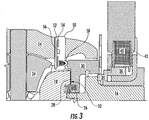
- FIG. 1 one embodiment of a wireless system 10 for spinning-components is depicted.
- the sensing system 10 is depicted in a locking differential assembly 12 to determine the axial position of the locking gear within a vehicle's locking differential assembly 12; however, the sensing system 10 may also be used in other systems including, but not limited to, power-take-off units, axle disconnect systems, etc.
- the differential assembly 12 includes a differential case 14.
- the differential case 14 is located in a differential housing (not shown) and is mounted for rotation in the differential housing.
- the differential case 14 includes a hollow interior space 14a.
- a differential spider shaft 16 is located within the differential case 14.
- the spider shaft 16 extends across the hollow interior space 14a of the differential case 14.
- an end portion 16a of the spider shaft 16 is secured within an aperture 14b of the differential case 14.
- the differential assembly 12 includes a differential gear arrangement having a first differential side gear 18, a second differential side gear (not shown), a first differential pinion gear 24 and a second differential pinion gear (not shown).
- the first differential side gear 18 is mounted on the end portion 16a of the spider shaft 16 within the differential case 14.
- the differential case 14 houses the differential gear arrangement. As shown in FIG. 1 , the spider shaft 16 can extend through an aperture 18a in the first differential side gear 18.
- the first differential side gear 18 has a set of teeth 20 circumferentially there around.
- the differential side gear teeth 20 are in selective meshed engagement with a set of teeth 22 on the first differential pinion gear 24.
- the differential side gear teeth 20 are also meshed with teeth on the second differential pinion gear (not shown).
- the differential side gear teeth 20 are on a first side 18a of the first differential side gear 18.
- the first side 1-8a faces inwardly into the differential case 14.
- the first-differential side gear 18 has a second side 18b opposite the first -side 18a.
- the second side faces outwardly.
- the second side 18b of the first differential side gear 18 has an axially extending pocket 18c extending into the first differential side gear 18.
- the pocket 18c receives a first end portion 26a of a biasing member 26 therein.
- the biasing member 26 may be, but is not limited to, a spring, a coil spring or a wave spring.
- the second side 18b of the first differential side gear 18 also has a set of teeth 28.
- the teeth 28 are located radially above the biasing member 26.
- a second end 26b of the biasing member 26 is in contact with a spinning component or cam ring 30.
- the cam ring 30 has a radially inner interior portion 30a, a radially outer interior portion 30b and a radially outer exterior portion 30c.
- the radially outer interior portion 30b and the radially outer exterior portion 30c are generally axially aligned with one another.
- the biasing member 26 is in contact with the radially inner interior portion 30a of the cam ring 30.
- the cam ring 30 also has a set of teeth 32 thereon.
- the teeth 32 are located on the radially inner interior portion 30a. More particularly, the teeth 32 are located radially above a contact point 26c of the biasing member 26 on the cam ring 30.
- the radially inner interior portion 30a and the radially outer interior portion 30b of the cam ring 30 are both located within the differential case 14.
- the radially outer exterior portion 30c is located out of the differential case 14 and extends through an axial opening 14c in the differential case 14.
- the radially outer exterior portion 30c, the radially outer interior portion 30b and the radially inner interior portion 30a may be one piece, unitary and integrally formed, or may be of individual pieces that are connected together.
- the radially outer exterior portion 30c of the cam ring 30 is in contact with an axially movable bushing 34.
- the bushing 34 is preferably a continuous, ring shaped structure.
- the bushing 34 may be constructed of a non-magnetic material, such as, but not limited to, plastic.
- the bushing 34 is located radially inboard and axially outboard from the radially outer exterior portion 30c of the cam ring 30.
- the bushing 34 is in contact with an-axially movable slide collar 36.
- the slide collar 36 is constructed of a metallic material that is susceptible to magnetic forces including, but notlimited to, steel.
- the slide collar 36 is located radially inboard of an electromagnet 38 of an actuator 46.
- the electromagnet 38 includes a coil 40 and a coil housing 42.
- the coil housing 42 is hollow and encloses the coil 40.
- the coil 40 includes multiple copper wire windings encased in a potting material within the coil housing 42. The wire windings of the coil 40 are connected to a source for electricity (not shown).
- the coil housing 42 may be one piece or several pieces connected together.
- the coil housing 42 and the electromagnet 38 may be located on the differential case 14.
- the coil housing 42 may be stationary with respect to the rotating differential case 14.
- a bushing 44 may be located between the coil housing 42 and the differential case 14 to facilitate relative rotation between the two.
- the slide collar 36 is located radially inward from the coil housing 42 and is in direct contact therewith.
- the slide collar 36 can have a complementary shape to the coil housing 42.
- a sensor assembly 50 is located in the differential case 14. More particularly, a sensor assembly 50 may be located in an aperture 14d that extends through the differential case 14. In one embodiment, the aperture 14d is a radially extending aperture 14d-extending through an outer wall of the differential case as shown in FIG. 1 .
- the sensor assembly 50 can include a printed circuit board (PCB) 52, a power source 54, a transmitter 56 and at least-one sensor 58.
- the transmitter 56 can include an antenna and other additional components.
- the PCB 52 can include a microcontroller.
- the PCB 52, power source 54, transmitter 56 and at least one sensor 58 can be located in a single housing 64, as shown in FIG. 1 , or may be located in individual separate housings in or on the differential ease 14.
- the sensor 58 can be a Hall effect sensor. Additionally, the sensor 58 can be a pressure sensor or a linear position sensor including, but not limited to, a resistive slide or a miniature-linear variable differential transformer. In one embodiment, the sensor assembly 50 can include a Hall effect sensor and a pressure sensor.
- the sensor assembly 50 has an interior portion 50a that extends radially into the hollow interior 14a of the differential case 14.
- the sensor 58 is positioned within the housing 64 or outside the housing 64 within the hollow interior of the differential case, axially adjacent the cam ring 30.
- the interior portion 50a is preferably located adjacent the radially outer interior portion 30b of the cam ring 30.
- the interior portion 50a may be axially located between the first differential side gear 18 and the cam ring 30 and radially located outboard of the differential pinion gear 24.
- the sensor assembly 50 is preferably fixed in a non-rotating fashion to the differential case 14.
- the differential case 14 is rotatable and when the differential case rotates, the sensor assembly 50 rotates with the differential case 14.
- the sensor assembly 50 is mounted such that there is no relative rotation between the differential case 14 and the sensor assembly 50.
- the sensor assembly 50 is fixed axially and radially within the differential case 14 for no relative movement with respect to the differential case 14.
- the sensor assembly 50 includes a pressure sensor 58 extending from a side surface 50b as shown in FIG. 2 .
- the pressure sensor 58 may include a biasing member 66, such as an elastomer or spring.
- the pressure sensor 58 is designed to be in contact with the radially outer interior portion 30b of the cam ring 30.
- the pressure sensor 58 may be in constant contact with the cam ring 30, or it may be separated from the cam ring 30 by a closeable gap. In either case, the axial amount the biasing member 66 is moved or compressed by the cam ring 30 is sensed by the pressure sensor 58.
- the biasing member 66 absorbs the linear translation of the cam ring 30 and generates a proportional-force on the pressure sensor-58.
- the pressure sensor 58 is an SP37 450kPa pressure sensor or similar. While this is one embodiment of a pressure sensor, other embodiments can include pressure sensors of other sizes and capacities.
- the sensed displacement can be converted to a signal, such as through a PCB 52, transmitter 56 and other electronic components in the sensor assembly 50.
- the signal can then be wirelessly transmitted by the transmitter 56 from the sensor assembly 50 to a transceiver 70 and/or controller.
- the signal may be sent through radio frequency transmissions or other frequencies.
- the sensor assembly 50 can include a Hall effect sensor 58 located thereon or therein. As shown in FIG. 1 , the sensor 58 is located in the sensor assembly 50. More particularly, the Hall effect sensor 58 may be located in the radially innermost portion of interior portion 50a of the sensor assembly 50. The interior portion 50a of the sensor assembly 50 may be located radially outward from the differential pinion gear 24 so that a gap 74 exists between them.
- a sensing element 76 is located on or in the radially outer interior portion 30b of the cam ring 30.
- One embodiment of the location, shape and size of the sensing element 76 is depicted in FIG. 1 ; however, other locations, shapes and/or sizes are possible.
- the sensing element 76 can be a magnet. As shown in FIG. 1 , the magnet 76 can be located on an inner side surface 30d of the radially outer interior portion 30b of the cam ring 30. The magnet 76 is located radially outward from the set of teeth 32 on the cam ring 30 and radially outward from the biasing member 26. It is also possible to locate the magnet 76 on a radially outer surface of the cam ring 30. Further, it is possible to locate the magnet 76-within the cam ring 30, such as within a depression or fully encased within the cam ring 30.
- FIG. 1 depicts the magnet 76 in a substantially horizontal orientation. That is, it is horizontal with respect to an axis of rotation A of the differential.
- the magnet 76 may also be oriented in substantially vertical orientation with respect to the axis of rotation A.
- the magnet 76 may also be oriented at an angle, such as at a 45-degree angle, with respect to the rotational axis A.
- the wireless system 10 may also include a receiver/demodulator 80.
- the receiver/demodulator 80 is depicted as located on the coil housing 42. More particularly, the receiver/demodulator 80 is located at a distance from the cam ring 30 or the differential case 14 so that a gap exists between the magnet 76, the sensor assembly 50 and the receiver/demodulator 80.
- the receiver/demodulator 80 may also be located on the differential housing or elsewhere in the vehicle. Alternatively, the receiver/demodulator 80 can be integrated into other existing vehicle electronics, such as the tire inflation system for the vehicle.
- the sensing step, signal creation, any operations by the printed circuit board 52 and the signal transmission can be powered by the power source 54 located in the sensor assembly 50.
- the power source 54 can be a rechargeable power source.
- the power source 54 is a battery. More particularly, the power source 54 is a battery that does not need to be replaced for the life of the vehicle.
- Power consumption from the power source 54 can be controlled by permitting the sensor assembly 50 to be placed into a sleep mode when it is not needed, such as when the vehicle is turned off or when the specific system is inactive.
- the controller (not depicted) can signal the sensor assembly 50 and/or power source 54 to "sleep".
- a wireless controller is part of the receiver/demodulator 80 and/or is in communication with sensor assembly 50 can signal the sensor assembly 50 and/or power source 54 to sleep.
- the controller can signal the sensor assembly 50 and/or power source 54 to turn back on.
- the controller and/or transceiver 70 can be located on the differential housing or elsewhere in the vehicle. Alternatively, the controller and/or the transceiver 70 can be integrated into other existing vehicle electronics, such as the vehicles tire inflation system.
- the wireless system 10 permits a signal indicating whether the differential is engaged or disengaged to be accurately and instantaneously determined and signaled to the confroller.
- the controller is communicatively coupled the sensor assembly 50.
- the controller receives signals generated by the sensors 58 and processes the received signals to determine the axial displacement of the spinning component. More particularly, the wireless system 10 determines the position of the cam ring 30 to determine whether it is engaged or disengaged with the differential side gear 18.
- the differential assembly 12 has two modes of operation. In a first mode of operation, the differential assembly 12 is not locked as depicted in FIG. 2 . The teeth 32 of the cam ring 30 and the differential side gear 18 are not engaged with one another. Instead, there is a gap between the teeth of the cam ring 30 and the differential side gear 18. This mode permits the differential side gears and pinion gears to rotate with respect to one another.
- the second mode of operation begins with electricity being sent to the coil 40 and the coil wires create a magnetic flux.
- the current in the coil 40 causes the coil housing 42 to become magnetized.
- the sum of the coil 40 flux and the coil housing 42 magnetism is greater than the sum of the spring force from the biasing member 26 between the cam ring 30 and the differential side gear 18 and friction force of the slide collar 36, which causes the slide collar 36 to move, as shown in FIG. 3 .
- the magnetic flux causes the slide collar 36 to move in the inboard axial direction.
- the slide collar 36 axially moves the bushing 34, which in turn axially moves the cam ring 30 in the inboard axial direction.
- the cam ring 30 axially moves into the differential side gear 18 causing the cam ring teeth 32 to engage with the matching side gear teeth 28.
- the sensor assembly 50 includes a pressure sensor 58
- the cam ring 30 compresses the biasing member 26, increasing pressure on the sensor 58.
- the sensor 58 processes the new axial position of the cam ring 30 and communicates to the transceiver 70.
- the inboard axial movement of the cam ring 30 moves the magnet 76 in the same direction
- the magnet 76 is located radially adjacent, such as at least radially beneath the sensor 58
- the sensed magnet 76 can be converted to a signal, such as through a printed circuit board 52 and/or other electronic components in the sensor assembly 50.
- the signal can then be wirelessly transmitted from the sensor assembly 50 to the receiver/demodulator 80.
- the signal may be sent such as through radio frequency transmissions, or other frequencies, or through inductive coupling.
- the sensing step, signal creation, any operations by the printed circuit board 52 and the signal transmission can be powered by the power source 54 located in the sensor assembly 50.
- the above-described wireless system 10 permits a signal indicating whether the differential assembly 12 is engaged or disengaged to be accurately and instantaneously determined and signaled to the controller. More particularly, the wireless system 12 determines the axial displacement of the cam ring 30 to determine whether it engages or disengages with the differential side gear 18.
- the electricity is removed from the coil 40.
- the biasing member 26 biases the cam ring 30 away from the differential side gear 18, thus, separating the two.
- the power source 54 can include an energy generation system 110 for the sensory assembly 50 with above-described system.
- the energy generation system 110 may be always employed, selectively-used, or used entirely on its own without the above-described wireless system 10.
- the wireless system 10 can include the power source 54 that may be used when the vehicle is not moving or the differential is not rotation, but the energy generation system 110 may be used at all other times.
- the energy generation system 110 may be connected to the power source 54 in the sensor assembly 50, a battery outside of the sensor assembly 50 and/or a capacitor- located in or adjacent the sensor assembly 50.
- the energy generation system 110 includes a coil 112, such as a metal coil of wires, located in or on the differential case 14.
- the coil 112 can be fixed with respect to the differential case 14 and rotates with it.
- the coil 112 is electronically connected to the power source 54 of the sensor assembly 50.
- the coil 112 is located adjacent, on or in the sensor assembly 50 so that an energy efficient, relatively short and inexpensive electrical connection can be made.
- the energy generation system 110 also includes a magnet 114 located in or on a stationary housing 116.
- the stationary housing 116 is radially outward from the differential case 114.
- the coil 112 and the magnet 114 are preferably located proximate on another. In one embodiment, the coil 112 and magnet 114 are located radially and axially aligned with one another, but may also be offset from one another in either the radial or axial direction.
- the coil 112 rotates by the magnet 114. Rotation of the coil 112 by the magnet 114 generates an electric current in the coil 112.
- the current can be provided to the power source 54 to assist in the maintaining the power source 54 or effectively replacing the power source 54 if needed.
- FIG. 4 depicts the energy generation system 110 including one coil 112 and magnet 114; however, the energy generation system 110 can include a plurality of coils and/or magnets.
- the additional coils/magnets can be used depending on the electrical power generating needs of the overall wireless system 10.
- one embodiment may include single magnet 114 located as described above, and then a plurality of spaced apart coils located as described above.
- the coil 112 or coils can generate electricity when magnetic flux goes through and around the coil 112.
- the energy generation system 110 can include a small weight and magnet that rotate about a spider shaft 16 or other structure.
- the weight and magnet are connected to each other, preferably directly attached to one another.
- the weight is connected to the differential case 14 and selective rotation of the differential case 14 imparts rotation to the weight.
- the inertia of the moving weight causes the magnet to pass adjacent to, or directly overor about, the coil 112.
- the magnet thus generates an electric current in the coil 112.
- the current can be provided to the power source or battery 54 to assist in maintaining the battery 54 or effectively replacing the battery 54 if needed. It can be appreciated that more than one weight/magnet system may be used to generate the electrical power needed for the system.
- the differential case 14 may include flux path features 210 formed integrally in the differential case 14 to provide a flux path.
- the flux path features 210 can be integrally formed, one piece and unitary with the differential case 14, and/or can be separately attached.
- the flux path features 210 can be constructed out of an electrically conductive material including, but not limited to, steel.
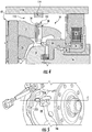
- FIGs. 5 and 6 show one embodiment of the flux path features 210
- the flux path features 210 may be of various shapes and sizes and the location of the flux path features 210 in relation to the differential case 14 can vary.
- FIGs. 5 and 6 depict a portion of the differential case 14 with the flux path features 210 located adjacent the electromagnet 38.
- the sensor assembly 50 is located in an axial opening 14e in the differential case 14 from the cam ring 30 as shown in FIG. 5 .
- the flux path features 210 of the differential case 14 are located between the electromagnet 38 and the sensor assembly 50.
- the flux path features 210 may include a curvilinear groove 210a in which a coil 212 is placed.
- the groove 210 is shown as circular or oval with a constant depth and width, but other shapes and dimensions are permissible.
- the coil 212 can be placed in the groove 210a so that the upper surface of the coil 212 is flush with the outer surface of the differential case 14 as shown in FIG. 6 .
- the flux path is depicted by arrows in the differential case 14 in FIG. 6 .
- the energy generation system can use inertia generated within the system to move a mass and create electricity.
- the energy generation system 310 is a shaker-type energy generation system as depicted in FIGs. 7a-b .
- the shaker-type energy system 310 includes a magnet 312 that selectively moves, such as axially, within a coil 314 of wire that at least partially surrounds the magnet 312.
- the coil 314 is connected to the power-source 54 to assist in maintaining the power source 54 or effectively replacing the power source 54 if needed.
- a biasing member 318 including, but not limited to, a spring, can be used to selectively located the magnet 312 in a home position.
- the biasing member 318 is located within a housing 320 that houses the magnet 312 as shown in FIG. 7b .
- the biasing member 318 may be located on one side of the magnet 312, but other locations and arrangements are permissible.
- the magnet 318 is permitted to slide in a larger diameter section 320a of the housing 320 compared with the section of the housing the houses the biasing member 318 as shown in FIG. 7b .
- the energy generation system 310 is connected to the differential case 14 so that for a predetermined amount of acceleration and/or declaration of the differential case 14, the magnet 312 compresses the biasing member 318 and an electric current is generated by virtue of the movement of the magnet 312 in the coil 314.
- the energy generation system 310 may be located on the differential case 14, partially within the outer wall of the differential case 14, completely within the outer wall of the differential case 14 or within the differential case 14.
- shaker-type energy systems 310 can be used based on the electrical power needs of the wireless system 10.
Landscapes
- Engineering & Computer Science (AREA)
- General Engineering & Computer Science (AREA)
- Mechanical Engineering (AREA)
- Physics & Mathematics (AREA)
- General Physics & Mathematics (AREA)
- Electromagnetism (AREA)
- Retarders (AREA)
- Measurement Of Length, Angles, Or The Like Using Electric Or Magnetic Means (AREA)
- Length Measuring Devices With Unspecified Measuring Means (AREA)
- Arrangements For Transmission Of Measured Signals (AREA)
Claims (15)
- Differenzialanordnung (12), die ein drahtloses System (10) zum Bestimmen der Verschiebung von Spinnkomponenten der Differenzialanordnung (12) aufweist, welche aufweist:ein Differenzialgehäuse (14) mit einem hohlen Innenraum (14a);eine Differenzialanordnung (12), enthaltend einen Aktuator, der einen Elektromagneten (38) mit einer Spule (40) und eine Spinnkomponente (30), die in selektivem Eingriff mit einer Differenzialgetriebeanordnung ist, enthält; undzumindest eine Sensoranordnung (50), die zumindest einen Sensor (58) enthält;wobei das Differenzialgehäuse (14) die Differenzialgetriebeanordnung aufnimmt, wobei der zumindest eine Sensor (58) direkt eine axiale Verschiebung der Spinnkomponente (30) erfasst, undwobei die Sensoranordnung (50) ein Signal erzeugt, das die axiale Verschiebung der Spinnkomponente (30) darstellt;dadurch gekennzeichnet, dassdie zumindest eine Sensoranordnung (50) nicht-drehbar an dem Differenzialgehäuse (14) befestigt ist und der zumindest eine Sensor (58) kommunikativ mit einer gedruckten Schaltungsplatte, einem Sender (56) und einer Energiequelle (54) gekoppelt ist,wobei der Sender (56) drahtlos mit einem Empfänger (80), der außerhalb des Differenzialgehäuses (14) positioniert ist, gekoppelt ist, undwobei ein Teil (50a) der Sensoranordnung (50) sich axial und radial innerhalb des Differenzialgehäuses (14) erstreckt und der zumindest eine Sensor (58) axial benachbart der Spinnkomponente (30) der Differenzialanordnung (12) in dem hohlen Innenraum (14a) des Differenzialgehäuses (14) positioniert ist.
- Differenzialanordnung (12) nach Anspruch 1, bei der die Energiequelle (54) eine wiederaufladbare Energiequelle ist.
- Differenzialanordnung (12) nach Anspruch 1, bei der die Energiequelle (54) eine Batterie ist.
- Differenzialanordnung (12) nach Anspruch 1, bei der die Energiequelle (54) weiterhin ein Energieerzeugungssystem (110) aufweist.
- Differenzialanordnung (12) nach Anspruch 4, bei der das Energieerzeugungssystem (110) ein System vom Schütteltyp ist.
- Differenzialanordnung (12) nach Anspruch 5, bei der das Energieerzeugungssystem (110) auf dem Differenzialgehäuse (14) positioniert ist.
- Differenzialanordnung (12) nach Anspruch 4, bei der das Energiesystem (110) zumindest eine Spule (112), die mit der Energiequelle (54) verbunden und an dem Differenzialgehäuse (14) benachbart der Sensoranordnung (50) befestigt ist, und zumindest einen Magneten (114), der mit einem stationären Gehäuse (116), das radial auswärts des Differenzialgehäuses (14) positioniert ist, verbunden ist, enthält.
- Differenzialanordnung (12) nach Anspruch 7, bei der das Differenzialgehäuse (14) zumindest ein in diesem integral gebildetes Flusspfadmerkmal (210) enthält.
- Differenzialanordnung (12) nach Anspruch 8, bei der das Flusspfadmerkmal (210) eine Nut (210a) enthält, die integral in dem Differenzialgehäuse (14) gebildet ist, wobei die Nut (210a) eine Spule (40) mit einer oberen Oberfläche, die eben mit einer äußeren Oberfläche des Differenzialgehäuses (14) ist, enthält.
- Differenzialanordnung (12) nach Anspruch 1, bei der der zumindest eine Sensor (58) ein Hall-Sensor ist, der ein Sensorelement hat, das an der Spinnkomponente (30) radial einwärts des Sensors (58) angebracht ist.
- Differenzialanordnung (12) nach Anspruch 1, bei der der zumindest eine Sensor (58) ein Drucksensor ist, der sich axial von der Sensoranordnung (50) weg zu der Spinnkomponente (30) hin erstreckt.
- Differenzialanordnung (12) nach Anspruch 1, weiterhin aufweisend eine Steuervorrichtung, die mit der Sensoranordnung (50) kommuniziert.
- Differenzialanordnung (12) nach Anspruch 1, weiterhin aufweisend ein Vorspannteil (26) mit einem ersten Ende und einem zweiten Ende, wobei das erste Ende mit der Differenzialgetriebeanordnung verbunden ist und das zweite Ende mit der Spinnkomponente (30) verbunden ist.
- Differenzialanordnung (12) nach Anspruch 1, bei der das Vorspannteil (26) eine Feder ist.
- Differenzialanordnung (12) nach Anspruch 1, bei der der Sender (56) Radiofrequenzsendungen verwendet.
Applications Claiming Priority (3)
| Application Number | Priority Date | Filing Date | Title |
|---|---|---|---|
| US201562202233P | 2015-08-07 | 2015-08-07 | |
| US201662311087P | 2016-03-21 | 2016-03-21 | |
| PCT/US2016/045704 WO2017027347A1 (en) | 2015-08-07 | 2016-08-05 | Wireless system for determining displacement of spinning components |
Publications (2)
| Publication Number | Publication Date |
|---|---|
| EP3332223A1 EP3332223A1 (de) | 2018-06-13 |
| EP3332223B1 true EP3332223B1 (de) | 2019-07-10 |
Family
ID=56843012
Family Applications (1)
| Application Number | Title | Priority Date | Filing Date |
|---|---|---|---|
| EP16758005.9A Not-in-force EP3332223B1 (de) | 2015-08-07 | 2016-08-05 | Drahtloses system zur verschiebungsbestimmung von spinnelementen |
Country Status (4)
| Country | Link |
|---|---|
| US (2) | US10422660B2 (de) |
| EP (1) | EP3332223B1 (de) |
| JP (1) | JP6493944B2 (de) |
| WO (1) | WO2017027347A1 (de) |
Cited By (1)
| Publication number | Priority date | Publication date | Assignee | Title |
|---|---|---|---|---|
| US11850896B2 (en) | 2013-03-12 | 2023-12-26 | Aperia Technologies, Inc. | System for tire inflation |
Families Citing this family (3)
| Publication number | Priority date | Publication date | Assignee | Title |
|---|---|---|---|---|
| CN110753806B (zh) * | 2017-05-09 | 2024-03-19 | 德纳汽车系统集团有限责任公司 | 差速器传感器装置和使用方法 |
| WO2018232262A1 (en) * | 2017-06-16 | 2018-12-20 | Eaton Intelligent Power Limited | Differential lock/unlock position detection |
| US11642920B2 (en) | 2018-11-27 | 2023-05-09 | Aperia Technologies, Inc. | Hub-integrated inflation system |
Family Cites Families (38)
| Publication number | Priority date | Publication date | Assignee | Title |
|---|---|---|---|---|
| US3996590A (en) * | 1961-02-02 | 1976-12-07 | Hammack Calvin M | Method and apparatus for automatically detecting and tracking moving objects and similar applications |
| DE2103381C3 (de) * | 1971-01-26 | 1978-09-21 | Daimler-Benz Ag, 7000 Stuttgart | Drehzahlgeber für die Impulsgabe zum Regeln des Schlupfes der Räder von Kraftfahrzeugen |
| US3927339A (en) * | 1971-12-07 | 1975-12-16 | Daimler Benz Ag | Frequency transmitters for producing control signals controlling the brake force in motor vehicle wheels |
| US4163208A (en) | 1975-12-18 | 1979-07-31 | Merz Ernest J | Automatic wireless tire pressure monitoring system |
| DE3463361D1 (en) * | 1983-08-02 | 1987-06-04 | Howa Machinery Ltd | Apparatus for controlling the winding speed of roving in roving frame |
| US5111440A (en) * | 1988-04-29 | 1992-05-05 | North American Philips Corporation | An apparatus for controlling the rotation and stabilizing the position of a magnet device |
| US5980256A (en) * | 1993-10-29 | 1999-11-09 | Carmein; David E. E. | Virtual reality system with enhanced sensory apparatus |
| US8169311B1 (en) | 1999-12-15 | 2012-05-01 | Automotive Technologies International, Inc. | Wireless transmission system for vehicular component control and monitoring |
| IT1295878B1 (it) * | 1997-10-24 | 1999-05-28 | Abb Kent Taylor Spa | Dispositivo di misura relativa di angoli, particolarmente per steli di valvole di regolazione e valvole rotative |
| EP1203960B2 (de) | 2000-11-06 | 2018-02-07 | Nsk Ltd | Wälzlagervorrichtung und Ring,der für die Wälzlagervorrichtung geeignet ist, mit integriertem Sensor |
| US6639399B2 (en) * | 2001-02-06 | 2003-10-28 | Delphi Technologies, Inc. | Target wheel sensor assembly for determining position and direction of motion of a rotating target wheel |
| DE10221878A1 (de) * | 2001-06-01 | 2003-01-16 | Omron Corp Kyoto | Berührender Versetzungsdetektor und -sensor |
| US20040132572A1 (en) | 2003-01-02 | 2004-07-08 | Eaton Corporation | Lock detection sensor |
| DE112004001448T5 (de) | 2003-08-29 | 2006-10-26 | Ntn Corp. | Drahtloses Sensorsystem und Radtraglagerbaugruppe unter Verwendung desselben |
| US7021127B2 (en) | 2004-01-12 | 2006-04-04 | Delphi Technologies, Inc. | Self-powered wireless sensor assembly for sensing angular position of the engine crankshaft in a vehicle |
| DE602004030160D1 (de) * | 2004-02-19 | 2010-12-30 | Mitsubishi Electric Corp | Magnetfelddetektor und stromdetektionseinrichtung, positionsdetektionseinrichtung und rotationsdetektionseinrichtung mit dem magnetfelddetektor |
| US7528597B2 (en) * | 2004-03-08 | 2009-05-05 | Digisensors, Inc. | Induction sensor |
| EP1803170B1 (de) | 2004-10-21 | 2011-06-22 | Société de Technologie Michelin | Energiesammelvorrichtung mit einstellbarer resonanzfrequenz |
| US7332881B2 (en) | 2004-10-28 | 2008-02-19 | Textron Inc. | AC drive system for electrically operated vehicle |
| US7211020B2 (en) | 2005-05-26 | 2007-05-01 | American Axle & Manufacturing, Inc. | Lockable differential with locking state detection system |
| JP2007002959A (ja) * | 2005-06-27 | 2007-01-11 | Gkn ドライブライン トルクテクノロジー株式会社 | 電磁アクチュエータ並びにこれを用いた電磁クラッチ及びデファレンシャル装置 |
| US7516826B2 (en) * | 2005-11-09 | 2009-04-14 | Custom Products Corporation | Electro-slip clutch |
| US7602271B2 (en) | 2006-08-21 | 2009-10-13 | American Axle & Manufacturing, Inc. | Electronically actuated apparatus using solenoid actuator with integrated sensor |
| WO2009147654A1 (en) * | 2008-06-02 | 2009-12-10 | Maradin Technologies Ltd. | Gimbaled scanning micro-mirror apparatus |
| US8405235B2 (en) | 2009-05-13 | 2013-03-26 | Ienergy Harvesting, Inc. | Energy harvesting device |
| US8109358B2 (en) | 2009-05-20 | 2012-02-07 | Eaton Corporation | Electronically controlled locking differential having under-dash control system |
| DE102009056088B4 (de) | 2009-11-30 | 2011-10-06 | Gkn Driveline International Gmbh | Differentialanordnung und Antriebsanordnung mit einer Differentialanordnung |
| CA2756470C (en) | 2010-11-01 | 2015-09-01 | Wheel Monitor Inc. | Monitoring system for controlling liftable and steer axles on trucks or tractor trailers |
| US8853870B2 (en) | 2011-05-04 | 2014-10-07 | The Commonwealth Of Australia | Vibration energy conversion device |
| US9182459B2 (en) * | 2011-09-08 | 2015-11-10 | Honeywell International Inc. | Wireless magnetic position sensor |
| US8989956B2 (en) | 2011-09-19 | 2015-03-24 | Bradley James DUNST | System, method and apparatus for real-time measurement of vehicle performance |
| US8694224B2 (en) | 2012-03-01 | 2014-04-08 | Magna Electronics Inc. | Vehicle yaw rate correction |
| US9973831B2 (en) | 2012-03-08 | 2018-05-15 | Husqvarna Ab | Data collection system and method for fleet management |
| JP6218813B2 (ja) | 2012-05-23 | 2017-10-25 | イートン コーポレーションEaton Corporation | 非回転の固定子及び電機子を有する電子作動式ロッキングディファレンシャル |
| EP2855188B1 (de) | 2013-01-23 | 2017-03-01 | Eaton Corporation | Sperrdifferentialanordnung |
| US9304142B1 (en) | 2013-03-12 | 2016-04-05 | A. Steve Gurganian | Energy harvesting zero-speed sensor device, method and system |
| JP6365190B2 (ja) * | 2014-09-30 | 2018-08-01 | ミツミ電機株式会社 | リニアアクチュエータ及び電動ブラシ、電動切削機及び電動エアポンプ |
| US10525779B2 (en) * | 2017-04-27 | 2020-01-07 | Pacific Industrial Co., Ltd. | Receiver |
-
2016
- 2016-08-05 WO PCT/US2016/045704 patent/WO2017027347A1/en active Application Filing
- 2016-08-05 US US15/750,954 patent/US10422660B2/en not_active Expired - Fee Related
- 2016-08-05 JP JP2018504914A patent/JP6493944B2/ja not_active Expired - Fee Related
- 2016-08-05 EP EP16758005.9A patent/EP3332223B1/de not_active Not-in-force
-
2019
- 2019-08-13 US US16/539,427 patent/US11209289B2/en active Active
Non-Patent Citations (1)
| Title |
|---|
| None * |
Cited By (1)
| Publication number | Priority date | Publication date | Assignee | Title |
|---|---|---|---|---|
| US11850896B2 (en) | 2013-03-12 | 2023-12-26 | Aperia Technologies, Inc. | System for tire inflation |
Also Published As
| Publication number | Publication date |
|---|---|
| US11209289B2 (en) | 2021-12-28 |
| US20190368897A1 (en) | 2019-12-05 |
| JP2018526631A (ja) | 2018-09-13 |
| US20180231395A1 (en) | 2018-08-16 |
| EP3332223A1 (de) | 2018-06-13 |
| JP6493944B2 (ja) | 2019-04-03 |
| WO2017027347A1 (en) | 2017-02-16 |
| US10422660B2 (en) | 2019-09-24 |
Similar Documents
| Publication | Publication Date | Title |
|---|---|---|
| US11209289B2 (en) | Wireless system for determining displacement of spinning components | |
| CN101960177B (zh) | 具有减速器的系统 | |
| US11142067B2 (en) | Differential sensor apparatus and method of use | |
| CN107209231B (zh) | 基于磁体的转角测量系统 | |
| KR101944871B1 (ko) | 조향 위치 및 토크 센서 | |
| CN102712341A (zh) | 用于检测转向力矩和转向角的装置及具有该装置的转向系统 | |
| EP1911988B1 (de) | Antriebsvorrichtung | |
| WO2015168046A1 (en) | Non-contact sensor for electromagnetic actuator assembly | |
| US7164265B2 (en) | Bearing assembly with rotation sensing device | |
| CN212721465U (zh) | 扭矩角度传感器 | |
| CN211391440U (zh) | 电动转向助力系统及其转矩传感装置 | |
| CN111555745A (zh) | 一种感应旋钮以及感应旋钮的控制方法 | |
| EP2680409A2 (de) | Motor | |
| CN102678915A (zh) | 旋转位置检测装置及具有其的变速机驱动装置 | |
| US20170307411A1 (en) | Position sensor | |
| JP5995764B2 (ja) | 温度計測機能を備えているロータ | |
| US20220299388A1 (en) | Dynamic torque sensing device of thread-on freewheel structure | |
| KR101189573B1 (ko) | 조향각 센서 일체형의 자동차용 스티어링 롤 커넥터 | |
| CN212343753U (zh) | 一种感应旋钮 | |
| EP3029442A1 (de) | Elektrofahrradmotor | |
| EP2202499A2 (de) | Drehmomentsensorvorrichtung | |
| CN111712689A (zh) | 手节气门传感器 | |
| CN211504002U (zh) | 踏板角度传感器 | |
| KR20140130296A (ko) | 비접촉식 인히비터 스위치 | |
| WO2012176011A1 (en) | Sensor unit for sensing the rotation speed of a rotatable element with respect to a fixed element and bearing assembly comprising such a sensor unit |
Legal Events
| Date | Code | Title | Description |
|---|---|---|---|
| STAA | Information on the status of an ep patent application or granted ep patent |
Free format text: STATUS: THE INTERNATIONAL PUBLICATION HAS BEEN MADE |
|
| PUAI | Public reference made under article 153(3) epc to a published international application that has entered the european phase |
Free format text: ORIGINAL CODE: 0009012 |
|
| STAA | Information on the status of an ep patent application or granted ep patent |
Free format text: STATUS: REQUEST FOR EXAMINATION WAS MADE |
|
| 17P | Request for examination filed |
Effective date: 20180201 |
|
| AK | Designated contracting states |
Kind code of ref document: A1 Designated state(s): AL AT BE BG CH CY CZ DE DK EE ES FI FR GB GR HR HU IE IS IT LI LT LU LV MC MK MT NL NO PL PT RO RS SE SI SK SM TR |
|
| AX | Request for extension of the european patent |
Extension state: BA ME |
|
| RIN1 | Information on inventor provided before grant (corrected) |
Inventor name: METZGER, SETH A. Inventor name: MITZEL, ANNE M. Inventor name: CREECH, MICHAEL Z. Inventor name: DAVIS, JUSTIN S. |
|
| DAV | Request for validation of the european patent (deleted) | ||
| DAX | Request for extension of the european patent (deleted) | ||
| GRAP | Despatch of communication of intention to grant a patent |
Free format text: ORIGINAL CODE: EPIDOSNIGR1 |
|
| STAA | Information on the status of an ep patent application or granted ep patent |
Free format text: STATUS: GRANT OF PATENT IS INTENDED |
|
| INTG | Intention to grant announced |
Effective date: 20190201 |
|
| GRAS | Grant fee paid |
Free format text: ORIGINAL CODE: EPIDOSNIGR3 |
|
| GRAA | (expected) grant |
Free format text: ORIGINAL CODE: 0009210 |
|
| STAA | Information on the status of an ep patent application or granted ep patent |
Free format text: STATUS: THE PATENT HAS BEEN GRANTED |
|
| AK | Designated contracting states |
Kind code of ref document: B1 Designated state(s): AL AT BE BG CH CY CZ DE DK EE ES FI FR GB GR HR HU IE IS IT LI LT LU LV MC MK MT NL NO PL PT RO RS SE SI SK SM TR |
|
| REG | Reference to a national code |
Ref country code: GB Ref legal event code: FG4D |
|
| REG | Reference to a national code |
Ref country code: CH Ref legal event code: EP Ref country code: AT Ref legal event code: REF Ref document number: 1154073 Country of ref document: AT Kind code of ref document: T Effective date: 20190715 |
|
| REG | Reference to a national code |
Ref country code: IE Ref legal event code: FG4D |
|
| REG | Reference to a national code |
Ref country code: DE Ref legal event code: R096 Ref document number: 602016016754 Country of ref document: DE |
|
| REG | Reference to a national code |
Ref country code: NL Ref legal event code: MP Effective date: 20190710 |
|
| REG | Reference to a national code |
Ref country code: LT Ref legal event code: MG4D |
|
| REG | Reference to a national code |
Ref country code: AT Ref legal event code: MK05 Ref document number: 1154073 Country of ref document: AT Kind code of ref document: T Effective date: 20190710 |
|
| PG25 | Lapsed in a contracting state [announced via postgrant information from national office to epo] |
Ref country code: FI Free format text: LAPSE BECAUSE OF FAILURE TO SUBMIT A TRANSLATION OF THE DESCRIPTION OR TO PAY THE FEE WITHIN THE PRESCRIBED TIME-LIMIT Effective date: 20190710 Ref country code: AT Free format text: LAPSE BECAUSE OF FAILURE TO SUBMIT A TRANSLATION OF THE DESCRIPTION OR TO PAY THE FEE WITHIN THE PRESCRIBED TIME-LIMIT Effective date: 20190710 Ref country code: NO Free format text: LAPSE BECAUSE OF FAILURE TO SUBMIT A TRANSLATION OF THE DESCRIPTION OR TO PAY THE FEE WITHIN THE PRESCRIBED TIME-LIMIT Effective date: 20191010 Ref country code: PT Free format text: LAPSE BECAUSE OF FAILURE TO SUBMIT A TRANSLATION OF THE DESCRIPTION OR TO PAY THE FEE WITHIN THE PRESCRIBED TIME-LIMIT Effective date: 20191111 Ref country code: HR Free format text: LAPSE BECAUSE OF FAILURE TO SUBMIT A TRANSLATION OF THE DESCRIPTION OR TO PAY THE FEE WITHIN THE PRESCRIBED TIME-LIMIT Effective date: 20190710 Ref country code: LT Free format text: LAPSE BECAUSE OF FAILURE TO SUBMIT A TRANSLATION OF THE DESCRIPTION OR TO PAY THE FEE WITHIN THE PRESCRIBED TIME-LIMIT Effective date: 20190710 Ref country code: BG Free format text: LAPSE BECAUSE OF FAILURE TO SUBMIT A TRANSLATION OF THE DESCRIPTION OR TO PAY THE FEE WITHIN THE PRESCRIBED TIME-LIMIT Effective date: 20191010 Ref country code: SE Free format text: LAPSE BECAUSE OF FAILURE TO SUBMIT A TRANSLATION OF THE DESCRIPTION OR TO PAY THE FEE WITHIN THE PRESCRIBED TIME-LIMIT Effective date: 20190710 Ref country code: NL Free format text: LAPSE BECAUSE OF FAILURE TO SUBMIT A TRANSLATION OF THE DESCRIPTION OR TO PAY THE FEE WITHIN THE PRESCRIBED TIME-LIMIT Effective date: 20190710 |
|
| PG25 | Lapsed in a contracting state [announced via postgrant information from national office to epo] |
Ref country code: AL Free format text: LAPSE BECAUSE OF FAILURE TO SUBMIT A TRANSLATION OF THE DESCRIPTION OR TO PAY THE FEE WITHIN THE PRESCRIBED TIME-LIMIT Effective date: 20190710 Ref country code: GR Free format text: LAPSE BECAUSE OF FAILURE TO SUBMIT A TRANSLATION OF THE DESCRIPTION OR TO PAY THE FEE WITHIN THE PRESCRIBED TIME-LIMIT Effective date: 20191011 Ref country code: IS Free format text: LAPSE BECAUSE OF FAILURE TO SUBMIT A TRANSLATION OF THE DESCRIPTION OR TO PAY THE FEE WITHIN THE PRESCRIBED TIME-LIMIT Effective date: 20191110 Ref country code: RS Free format text: LAPSE BECAUSE OF FAILURE TO SUBMIT A TRANSLATION OF THE DESCRIPTION OR TO PAY THE FEE WITHIN THE PRESCRIBED TIME-LIMIT Effective date: 20190710 Ref country code: LV Free format text: LAPSE BECAUSE OF FAILURE TO SUBMIT A TRANSLATION OF THE DESCRIPTION OR TO PAY THE FEE WITHIN THE PRESCRIBED TIME-LIMIT Effective date: 20190710 Ref country code: ES Free format text: LAPSE BECAUSE OF FAILURE TO SUBMIT A TRANSLATION OF THE DESCRIPTION OR TO PAY THE FEE WITHIN THE PRESCRIBED TIME-LIMIT Effective date: 20190710 |
|
| PG25 | Lapsed in a contracting state [announced via postgrant information from national office to epo] |
Ref country code: TR Free format text: LAPSE BECAUSE OF FAILURE TO SUBMIT A TRANSLATION OF THE DESCRIPTION OR TO PAY THE FEE WITHIN THE PRESCRIBED TIME-LIMIT Effective date: 20190710 |
|
| PG25 | Lapsed in a contracting state [announced via postgrant information from national office to epo] |
Ref country code: IT Free format text: LAPSE BECAUSE OF FAILURE TO SUBMIT A TRANSLATION OF THE DESCRIPTION OR TO PAY THE FEE WITHIN THE PRESCRIBED TIME-LIMIT Effective date: 20190710 Ref country code: RO Free format text: LAPSE BECAUSE OF FAILURE TO SUBMIT A TRANSLATION OF THE DESCRIPTION OR TO PAY THE FEE WITHIN THE PRESCRIBED TIME-LIMIT Effective date: 20190710 Ref country code: PL Free format text: LAPSE BECAUSE OF FAILURE TO SUBMIT A TRANSLATION OF THE DESCRIPTION OR TO PAY THE FEE WITHIN THE PRESCRIBED TIME-LIMIT Effective date: 20190710 Ref country code: DK Free format text: LAPSE BECAUSE OF FAILURE TO SUBMIT A TRANSLATION OF THE DESCRIPTION OR TO PAY THE FEE WITHIN THE PRESCRIBED TIME-LIMIT Effective date: 20190710 Ref country code: EE Free format text: LAPSE BECAUSE OF FAILURE TO SUBMIT A TRANSLATION OF THE DESCRIPTION OR TO PAY THE FEE WITHIN THE PRESCRIBED TIME-LIMIT Effective date: 20190710 |
|
| PG25 | Lapsed in a contracting state [announced via postgrant information from national office to epo] |
Ref country code: CH Free format text: LAPSE BECAUSE OF NON-PAYMENT OF DUE FEES Effective date: 20190831 Ref country code: LI Free format text: LAPSE BECAUSE OF NON-PAYMENT OF DUE FEES Effective date: 20190831 Ref country code: CZ Free format text: LAPSE BECAUSE OF FAILURE TO SUBMIT A TRANSLATION OF THE DESCRIPTION OR TO PAY THE FEE WITHIN THE PRESCRIBED TIME-LIMIT Effective date: 20190710 Ref country code: IS Free format text: LAPSE BECAUSE OF FAILURE TO SUBMIT A TRANSLATION OF THE DESCRIPTION OR TO PAY THE FEE WITHIN THE PRESCRIBED TIME-LIMIT Effective date: 20200224 Ref country code: LU Free format text: LAPSE BECAUSE OF NON-PAYMENT OF DUE FEES Effective date: 20190805 Ref country code: SM Free format text: LAPSE BECAUSE OF FAILURE TO SUBMIT A TRANSLATION OF THE DESCRIPTION OR TO PAY THE FEE WITHIN THE PRESCRIBED TIME-LIMIT Effective date: 20190710 Ref country code: SK Free format text: LAPSE BECAUSE OF FAILURE TO SUBMIT A TRANSLATION OF THE DESCRIPTION OR TO PAY THE FEE WITHIN THE PRESCRIBED TIME-LIMIT Effective date: 20190710 Ref country code: MC Free format text: LAPSE BECAUSE OF FAILURE TO SUBMIT A TRANSLATION OF THE DESCRIPTION OR TO PAY THE FEE WITHIN THE PRESCRIBED TIME-LIMIT Effective date: 20190710 |
|
| REG | Reference to a national code |
Ref country code: BE Ref legal event code: MM Effective date: 20190831 |
|
| REG | Reference to a national code |
Ref country code: DE Ref legal event code: R097 Ref document number: 602016016754 Country of ref document: DE |
|
| PLBE | No opposition filed within time limit |
Free format text: ORIGINAL CODE: 0009261 |
|
| STAA | Information on the status of an ep patent application or granted ep patent |
Free format text: STATUS: NO OPPOSITION FILED WITHIN TIME LIMIT |
|
| PG2D | Information on lapse in contracting state deleted |
Ref country code: IS |
|
| PG25 | Lapsed in a contracting state [announced via postgrant information from national office to epo] |
Ref country code: IE Free format text: LAPSE BECAUSE OF NON-PAYMENT OF DUE FEES Effective date: 20190805 |
|
| 26N | No opposition filed |
Effective date: 20200603 |
|
| PG25 | Lapsed in a contracting state [announced via postgrant information from national office to epo] |
Ref country code: BE Free format text: LAPSE BECAUSE OF NON-PAYMENT OF DUE FEES Effective date: 20190831 Ref country code: SI Free format text: LAPSE BECAUSE OF FAILURE TO SUBMIT A TRANSLATION OF THE DESCRIPTION OR TO PAY THE FEE WITHIN THE PRESCRIBED TIME-LIMIT Effective date: 20190710 |
|
| PG25 | Lapsed in a contracting state [announced via postgrant information from national office to epo] |
Ref country code: FR Free format text: LAPSE BECAUSE OF NON-PAYMENT OF DUE FEES Effective date: 20190910 |
|
| GBPC | Gb: european patent ceased through non-payment of renewal fee |
Effective date: 20200805 |
|
| PG25 | Lapsed in a contracting state [announced via postgrant information from national office to epo] |
Ref country code: CY Free format text: LAPSE BECAUSE OF FAILURE TO SUBMIT A TRANSLATION OF THE DESCRIPTION OR TO PAY THE FEE WITHIN THE PRESCRIBED TIME-LIMIT Effective date: 20190710 |
|
| PG25 | Lapsed in a contracting state [announced via postgrant information from national office to epo] |
Ref country code: MT Free format text: LAPSE BECAUSE OF FAILURE TO SUBMIT A TRANSLATION OF THE DESCRIPTION OR TO PAY THE FEE WITHIN THE PRESCRIBED TIME-LIMIT Effective date: 20190710 Ref country code: HU Free format text: LAPSE BECAUSE OF FAILURE TO SUBMIT A TRANSLATION OF THE DESCRIPTION OR TO PAY THE FEE WITHIN THE PRESCRIBED TIME-LIMIT; INVALID AB INITIO Effective date: 20160805 |
|
| PG25 | Lapsed in a contracting state [announced via postgrant information from national office to epo] |
Ref country code: GB Free format text: LAPSE BECAUSE OF NON-PAYMENT OF DUE FEES Effective date: 20200805 |
|
| PG25 | Lapsed in a contracting state [announced via postgrant information from national office to epo] |
Ref country code: MK Free format text: LAPSE BECAUSE OF FAILURE TO SUBMIT A TRANSLATION OF THE DESCRIPTION OR TO PAY THE FEE WITHIN THE PRESCRIBED TIME-LIMIT Effective date: 20190710 |
|
| PGFP | Annual fee paid to national office [announced via postgrant information from national office to epo] |
Ref country code: DE Payment date: 20220720 Year of fee payment: 7 |
|
| REG | Reference to a national code |
Ref country code: DE Ref legal event code: R119 Ref document number: 602016016754 Country of ref document: DE |