EP3331782B1 - Improved linear motion conveyor - Google Patents
Improved linear motion conveyor Download PDFInfo
- Publication number
- EP3331782B1 EP3331782B1 EP16833475.3A EP16833475A EP3331782B1 EP 3331782 B1 EP3331782 B1 EP 3331782B1 EP 16833475 A EP16833475 A EP 16833475A EP 3331782 B1 EP3331782 B1 EP 3331782B1
- Authority
- EP
- European Patent Office
- Prior art keywords
- conveyor bed
- drive
- elongated conveyor
- elongated
- movement
- Prior art date
- Legal status (The legal status is an assumption and is not a legal conclusion. Google has not performed a legal analysis and makes no representation as to the accuracy of the status listed.)
- Active
Links
Images






Classifications
-
- B—PERFORMING OPERATIONS; TRANSPORTING
- B65—CONVEYING; PACKING; STORING; HANDLING THIN OR FILAMENTARY MATERIAL
- B65G—TRANSPORT OR STORAGE DEVICES, e.g. CONVEYORS FOR LOADING OR TIPPING, SHOP CONVEYOR SYSTEMS OR PNEUMATIC TUBE CONVEYORS
- B65G27/00—Jigging conveyors
- B65G27/10—Applications of devices for generating or transmitting jigging movements
- B65G27/32—Applications of devices for generating or transmitting jigging movements with means for controlling direction, frequency or amplitude of vibration or shaking movement
-
- B—PERFORMING OPERATIONS; TRANSPORTING
- B65—CONVEYING; PACKING; STORING; HANDLING THIN OR FILAMENTARY MATERIAL
- B65G—TRANSPORT OR STORAGE DEVICES, e.g. CONVEYORS FOR LOADING OR TIPPING, SHOP CONVEYOR SYSTEMS OR PNEUMATIC TUBE CONVEYORS
- B65G27/00—Jigging conveyors
- B65G27/08—Supports or mountings for load-carriers, e.g. framework, bases, spring arrangements
-
- B—PERFORMING OPERATIONS; TRANSPORTING
- B65—CONVEYING; PACKING; STORING; HANDLING THIN OR FILAMENTARY MATERIAL
- B65G—TRANSPORT OR STORAGE DEVICES, e.g. CONVEYORS FOR LOADING OR TIPPING, SHOP CONVEYOR SYSTEMS OR PNEUMATIC TUBE CONVEYORS
- B65G27/00—Jigging conveyors
- B65G27/10—Applications of devices for generating or transmitting jigging movements
- B65G27/16—Applications of devices for generating or transmitting jigging movements of vibrators, i.e. devices for producing movements of high frequency and small amplitude
- B65G27/18—Mechanical devices
- B65G27/20—Mechanical devices rotating unbalanced masses
Definitions
- the present invention relates to a linear motion conveyor, and more specifically to a linear motion conveyor having a drive assembly which may be readily and selectively adjusted so as to impart motion to a product being transported by the linear motion conveyor, in opposite first and second directions, or to further stop the motion of product along the linear motion conveyor.
- linear motion conveyors or what are sometimes referred to "differential impulse" conveyors include a generally elongated, horizontal tray or pan having a planar surface for transporting goods thereon.
- the tray is moved slowly forward to convey the goods with respect to the tray, and then is pulled rearwardly at a higher return speed so that the goods slide along the tray.
- the prior art acknowledges that one of the significant advantage of these linear motion conveyors is that fragile goods which are being transported on same may move along in a manner that does not tend to damage them because the products do not roll or tumble or move out of contact with the underlying conveying surface.
- a linear motion conveyor which operates in the manner, as described above, is the subject matter of the present device.
- US 2014/332351 A1 describes a linear motion conveyor according to the preamble of claim 1.
- the present invention relates to a linear motion conveyor according to claim 1.
- the present invention will be described in greater detail hereinafter.
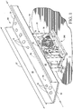
- the improved linear motion conveyor of the present invention 10 generally comprises a stationary base 200, a drive assembly 79, a frame assembly 20, a counterweight 40, and an elongated conveyor bed 60.
- the improved linear motion conveyor of the present invention is generally indicated by the numeral 10 in Figs. 1 and following.
- the invention 10 is supported on the stationary base 200 which, in turn, rests upon an underlying supporting surface which is generally indicated by the numeral 11.
- the underlying supporting surface may comprise a supporting floor of a factory, or other supporting surface located therebeneath.
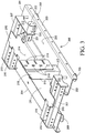
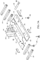
- the stationary base 200 ( Figures 3 , 3A ) is generally rectilinear in configuration and has a first end portion 201; a second end portion 202; a first side portion 203; a second side portion 204; a top surface 205; and a bottom surface 206.
- the frame spring mounts 207 ( Fig. 3 ) are formed of box beam members and are fixedly attached to the top surface 205 and are proximate to the first end, or portion 201, and proximate the second end, or portion 202 and extend transversely between the first side portion 203, and second side portion 204, respectively.
- a plurality of spaced and generally longitudinally aligned fastener holes are formed in each opposing end portion of the translation frame spring mounts 207, and which receive conventional fasteners 16. The fasteners secure the frame assembly 20 to the stationary base 200.
- Counterweight spring mounts 210 are similarly formed of box beam members and which are fixedly attached to the top surface 205, and located proximate to the first end portion 201 and the second end portion 202, and inwardly of the translation frame spring mounts 207. These structures extend transversely between the first side portion 203 and the second side portion 204. A plurality of generally longitudinally aligned fastener holes are formed in each opposing end portion of the counterweight spring mounts 210, and receive conventional fasteners 16 which secure the counterweight 40 to the stationary base 200.
- a supporting surface or platform 211 and which includes end caps 212, 213 are structurally attached to and communicate between proximate end portions of the translation frame spring mounts 207 and the counterweight spring mounts 210, respectively.
- the end caps 212, 213 provide additional structural rigidity and maintain the spaced distance between the spring mounts 207, 210.
- a raised elongate platform 211 extends between the two spaced apart counterweight spring mounts 210 and is medially positioned between the first side 203 and the second side 204.
- the raised and elongated platform, or supporting surface 211 provides a planar surface 214 which carries and supports various subassemblies of the drive assembly 79 and which will be discussed, below.
- a vertical motor mount 215 ( Fig. 3 ) is structurally attached to the stationary base 200, and is spaced from the counterweight spring mount 210, and fixedly located proximate the second end 202.
- the vertical motor about 215 has a lower end 217 which is structurally attached to the top surface 205 of the stationary base 200; and an upper end 216 which is located distally from the top surface 205.
- a plurality of spaced and vertically elongated holes 218 and a plurality of spaced and horizontally elongated holes 219 are formed in the vertical motor mount 215.
- the elongated holes 218 and 219 provide a means for horizontal and vertical adjustment of a portion of the drive assembly 79 relative to the stationary base 200.
- the selective positioning of a portion of the drive assembly 79, relative to the stationary base 200 is effective in determining the frequency of oscillation of the elongated conveyor bed 60, and counterweight 40, and the resulting direction of movement of product 15 carried on a product transporting surface 64 of the elongated conveyor bed 60. ( Fig. 1 ).
- a pivot axle 220 ( Fig. 3 ) having a box beam sleeve 221, and a disk shaped end cap 222 is carried by the stationary base 200, and located inwardly relative to the counterweight spring mount 210, and proximate the first end 201, and the first side 203 respectively.
- the pivot axle 220 is generally cylindrical in shape, horizontally oriented, and extends transversely to the stationary base 200 and is partially, axially carried in a channel (not shown) and which is defined by the box beam sleeve 221.
- the pivot axle 220 provides a pivot point for rotational movement of a powering unit 70 ( Fig. 9 ), and which is a subassembly of the drive assembly 79.
- the stationary base 200 is supported on an underlying supporting surface 11.
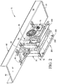
- a plurality of spaced leveling feet 209 which communicate with the bottom 206 ( Fig. 2 ) of the stationary base 200 provide a means for precisely leveling the invention 10 in its operating environment.
- the precise leveling of the invention 10 is important because inclines, declines, slants and the like of the invention 10 will affect product 15 movement on the product transporting surface 64.
- the frame assembly 20 is generally indicated by the numeral 20 ( Figs.4 , 5 ) and communicates between the stationary base 200, and the elongated conveyor bed 60.
- the frame 20 facilitates substantially parallel movement of the elongated conveyor bed 60 although it is recognized movement of the elongated conveyor bed 60 upon the translation frame 20 includes some minor component of vertical movement which is anticipated to be less than approximately 2% of the amount of horizontal movement.
- the translation frame 20 includes a first spring leg 21; a second spring leg 22; a third spring leg 23; and a fourth spring leg 25.
- Each of the respective spring legs 21, 22, 23, 24 has a lower/bottom or first end which is located proximate the stationary base 200, and which is designated by the letter “b" (21b, 22b, 23b, 24b); and an upper/top or second end which is located proximate to the elongated conveyor bed 60, and which is designated by the letter “a” (21a, 22a, 23a, 24a).
- Each of the respective spring legs 21, 22, 23, 24 is formed of a spring steel, or more commonly a synthetic composite such as, but not limited to, laminated fiberglass, carbon fiber, or the like.
- the respective spring legs 21, 22, 23, 24 are strong, resilient, durable and resistant to torsion/twisting forces so as to impede any "yawing" motion of the elongated conveyor bed 60 during operation.
- Each of the respective spring legs 21, 22, 23, 24 are spaced apart from the other legs, and are substantially parallel to the others.
- the respective spring legs 21, 22, 23, 24 provide an interconnection between the stationary base 200, and the elongated conveyor bed 60.
- the length of the respective spring legs 21, 22, 23, 24 from the upper/top end 21a, 22a, 23a, 24a, to the lower/bottom end 21b, 22b, 23b, 24b positionally maintains the elongated conveyor bed 60 in a predetermined spaced relationship above the stationary base 200.
- Each of the respective spring legs 21, 22, 23, 24 defines plural fastener holes (not shown) in each opposing end portion (a, b) for cooperation with a conventional fastener 16.
- the fasteners pass through the respective spring legs so as to secure the respective spring legs 21, 22, 23, 24 to the spring mounts 207 which are mounted on the stationary base 200 respectively and to the elongated conveyor bed 60.
- Reinforcing plates 28 ( Fig. 2 ) define fastener holes (not shown) that align with the fastener holes (not shown) and which are formed in the opposing end portions (a, b) of the spring legs 21, 22, 23, 24.
- the interconnection of the respective spring leg 21, 22, 23, 24 ends (a, b) to the elongated conveyor bed 60, and to the stationary base 200 eliminate any "pivotal" interconnection therebetween.
- the fixed interconnection of the respective spring legs 21, 22, 23, 24 to the elongated conveyor bed 60, and the stationary frame 200 eliminates the need for bearings at the interconnections, and also reduces wear, and tear and the maintenance which is necessary to support the movable elongated conveyor bed 60.
- the fixed interconnection of the respective spring legs 21, 22, 23, 24 relative to the elongated conveyor bed 60, and the stationary base 200 provides for a substantially continuous tension to be generated as the elongated conveyor bed 60 is moved from a first position 25, ( Figure 15 ) to a second position 26 ( Figure 15 ) along a longitudinal axis 63 of the elongated conveyor bed 60.
- This reciprocal movement imparts predetermined movement to the product 15 and which is carried on a product supporting surface 64.
- the use of the respective spring legs 21, 22, 23, 24 and the fixed interconnections has a tendency to reduce the noise of operation, and further reduce the overall mass of the invention 10.
- the reduction of noise is attributable, at least in part, to the removal of movable/pivotal interconnections (e.g. bearings) which necessarily have some amount of "play" to facilitate movement and which may be exacerbated after periods of use.
- the frame 20, ( Fig. 4 ) and more specifically the top ends 21a, 22a, 23a, 24a of the spring legs 21, 22, 23, 24 are moveable along a predetermined reciprocal course of travel that is generally indicated by the numeral 30.
- the course of travel 30 is defined between a first, or forwardly directed position 31, ( Fig. 15 ) and a second, opposite, and rearwardly located position 32.
- the frame 20 is reciprocally moveable along this course of travel 30 at different velocities in order to achieve the benefits of the present invention.
- the present invention 10 also includes a reciprocally moveable, and elongated conveyor bed which is generally indicated by the numeral 60.
- the elongated conveyor bed 60 has a first end 61, and an opposite second end 62. ( Fig. 1 ). Still further, the elongated conveyor bed 60 is generally defined by a longitudinal axis which is indicated by the line labeled 63.
- the elongated conveyor bed 60 has a product transporting surface 64, which is operable to be reciprocally moved in opposite directions, and at varying velocities so as to cause a product 15, which is deposited on the product transporting surface 64, to move between the opposite first and second ends 61 and 62 in a predetermined manner.
- the elongated conveyor bed also has a pair of spaced, substantially vertically disposed sidewalls 66 which confine the product 15 on the product transporting surface 64.
- the elongated conveyor bed 60 also has a bottom surface 67. ( Fig. 4 ).
- Mounting brackets 68 ( Fig. 4 ) are carried on the bottom surface 67, and are spacedly arrayed between the first and second ends 61 and 62, and located laterally inwardly relative to the spaced sidewalls 66.
- transverse spring leg mounts 65 interconnect with the mounting brackets 68, and also with the upper/top end portions 21a, 22a, 23a, 24a of the spring legs 21, 22, 23, 24.
- the upper/top ends 21a, 22a, 23a, 24a are fixedly attached with conventional fasteners 16, and reinforcing plates 28 to the transverse spring leg mounts 65.
- a drive frame 69 ( Fig. 6 ) and which is formed of a plurality of interconnected beams, and struts, is carried on the bottom surface 67 of the elongated conveyor bed 60.
- the drive frame 69 is located in spaced relation relative to the second end portion 62, is and generally centrally positioned between the spaced apart sidewalls 66.
- the drive frame 69 carries a generally horizontal inwardly extending driver member 12 that interconnects with the eccentric drive unit 300, and which will be discussed in greater detail, hereinafter.
- the drive member 12 has a first end portion 12a that is proximate a medial portion of the elongated conveyor bed 60, and a second end portion 12b that is proximate to the second end 62.
- the drive member is formed of a flexible or resilient material which will allow it to flex about its longitudinal axis.
- the present invention 10 includes a counter weight which is generally indicated by the numeral 40, ( Figs. 7 , 8 , 14 ) and which is carried in a location which is vertically, below, the elongated conveyor bed 60, and vertically above the drive assembly 79.
- the counter weight 40 generally comprises a slab weight frame 39; a slab weight 41; and individual spring legs 49, 50, 51, 52 respectively.
- the slab weight frame 39 is generally rectilinear in configuration and has a first end portion 42; a second end portion 43; a first side portion 44; a second side portion 45; a top 46; a bottom 47; and having a dimensional thickness 48.
- a medial cavity 41 is defined in the top 46 and releasably carries the slab weight 41a therein.
- the respective spring legs 49, 50, 51, and 52 are substantially similar in length, and width dimensions to each other, and further have an upper/top end portion designated by the letter "a", and a lower/bottom end portion designated by the letter "b".
- the respective spring legs 49, 50, 51 and 52 are located in predetermined, substantially parallel, spaced relation, relative to each other.
- the spring legs 49, 50, 51 and 52 are further located at the first end 42, and second end 43, and in the corners of the slab weight frame 39.
- the upper/top end portions 49a, 50a, 51a, 52a are fixedly attached to the slab weight frame 39 by conventional fasteners 16, and reinforcing plates 28 as earlier described.
- the lower/bottom end portions 49b, 50b, 51b, 52b are fixedly attached to the counterweight spring mounts 210 of the stationary base 200 with reinforcing plates 28 and conventional fasteners 16.
- the fixed attachment of the respective spring legs 49, 50, 51, 52 to the slab weight frame 39, and to the counterweight spring mounts 210 positionally maintains the respective spring legs 49, 50, 51 and 52 in substantially parallel, spaced relation.
- the respective spring legs 49, 50, 51, 52 are preferably formed of a spring steel, or more commonly, of a known composite such as, but not limited to, laminated fiberglass, carbon fiber, or the like and which is strong, resilient, durable, and substantially resistant to torsion/twisting forces. This materially impedes "yawing" movement of the counterweight 40 during operation.
- the slab weight 41 which provides various operational features of the present invention 10, is here illustrated as being a substantially rectilinear shaped main body having a predetermined weight. However, it will be recognized that other shapes would work with equal success, and the weight of the slab weight 41 may be adjusted by varying the thickness 48 or composition of the slab weight 41 without changing the length and width dimensions thereof, so that the slab weight 41 may be positionally maintained within the cavity (not shown) defined in the top 46 of the slab weight frame 39.
- a drive frame 53 which is formed of plural interconnected beams and struts is carried on the bottom 47 of the slab weight frame 39.
- the drive frame 53 is located proximate the second end 43, and generally centrally between the first side 44 and the second side 45.
- the drive frame 53 carries a flexible drive member 54 that interconnects with, or is coupled with, the eccentric drive unit 300, and will be discussed in greater detail, hereinafter.
- the drive member 54 has a first end portion 54a which is located proximate to the first end portion 42, and a second end portion 54b proximate to the second end 43.
- the counter weight 40 is moveable along a reciprocal path of travel that is generally indicated by the numeral 56. ( Fig. 15 ).
- the reciprocal path of travel 56 is defined between a first, forward oriented position 57, and a second, rearward oriented position 58.
- the repeated reciprocal motion of the counter weight 40 as will be described, hereinafter, provides an assortment of operational characteristics for the elongated conveyor bed 60.
- the drive assembly 79 ( Figures 9-13 ) includes various interconnected subassemblies, all of which will be described in detail.
- the drive assembly 79 is supported by the stationary base 200, and is further oriented and operationally coupled in force transmitting relation relative to the elongated conveyor bed 60, and to the counterweight 40, so as to impart predetermined reciprocal motion to the same to achieve the benefits of the present invention 10.
- the major subassemblies of the drive assembly 79 are a powering unit 70; the vertical motor mount 215; the pivot axle 220 which is supported by the stationary base 200; and an eccentric drive unit 300.
- the powering unit 70 generally provides a selectively energizable motor 90, which is mounted on a housing 71.
- the powering unit further includes an endless drive belt 94 and a drive wheel 96.
- the housing 71 is somewhat generally rectilinear in configuration and further has a first end 72; a second end 73; a top 74; a bottom 75; a first side 76; and a second side 77.
- the housing 71 fixedly carries the selectively energizable motor 90 on the second side 77.
- the selectively energizable motor 90 further has an output shaft 91 which extends transversely through a shaft orifice 78, and which is defined in the housing 71 so that the output shaft 91 extends transversely through the housing 71 and perpendicularly outwardly from the first side 76 thereof.
- a drive pulley, or shim 93 is carried on the output shaft 92 and frictionally engages the endless drive belt 94 which communicates force to the drive wheel 96 so as to transfer rotational motion of the output shaft 91 thereto.
- the drive wheel 96 is carried on, or positioned on the first side 76 of the housing 71, and on a first axle 92.
- the first axle 71 is journaled in bearings (not shown), and a bearing block (not shown), and is carried by the housing 71 and is further spaced apart from the drive pulley 93.
- the drive wheel 96 has a diameter larger than a diameter of the drive pulley 93 so as to function as a reduction gear.
- a pivot axle aperture or hole 82 is defined by the housing 71, and is located adjacent to the first end 72, and the bottom 75. The aperture 82 extends transversely through the housing 71. The pivot axle aperture 82 axially receives the pivot axle 220 and which is carried by the stationary base 200 so that the drive unit 70 and its attached components may pivot and move along a radial arc 83 relative to the pivot axle 220. ( Fig. 15 ).
- a mounting flange 80 is carried at the second end of the housing 71.
- the mounting flange 80 defines a plurality of vertically elongated holes 81 for receiving fasteners (not shown).
- the fasteners secure the mounting flange 80 to the vertical motor mount 215.
- the vertically elongated holes 81 permit the drive unit 70, and its attached components to be adjustably positioned relative to the vertical motor mount 215, as the drive unit 70 is pivoted about the pivot axle 220.
- the pivoting of the drive unit 70 about the pivot axle 220 causes the powering unit 70 to move along the radial arc identified as 83. ( Fig. 15 ).
- the powering unit 70 may be rendered selectively moveable along the radial arc 83 by employing any number of other assemblies including all manner of pneumatic or hydraulic pistons, gear drives, jackscrews and the like, and which can be selectively electrically or mechanically controlled so as to achieve the numerous benefits of the present invention.
- a moving means is generally identified as element 85. ( Fig 15 ).
- the operable coupling of the output shaft 91 to the first axle 92 may be done by conventional means, that is, by belt, sprocket and chain, or direct coupling to the first axle 92 to effect the rotation of the first axle 92 in a given rotational direction.
- the selectively energizable motor 90 may be coupled to suitable electronic controls (not shown) to effect the selective energizing of the motor 90 to initiate and stop the operation of the present invention 10, or further to selectively move the powering unit 70 to given operational locations along the radial arc 83 and which achieves the benefits of the invention which are disclosed.
- the first drive wheel 100 has a substantially circular main body 101 which is defined by a peripheral edge 102.
- the circular main body 101 has a first outwardly facing surface 103; and an opposite, second inwardly facing surface 104.
- An axle aperture (not shown) is formed substantially centrally thereof, and is operable to mateingly couple to one end of the first axle 92, and which is located opposite to the drive wheel 96.
- the first drive plate 100 ( Figs. 9 , 10 ) has a multiplicity of through holes or apertures 105 which are formed in a given pattern therein.
- the area of the first drive plate 100 which is located opposite the plurality of through holes or apertures 105 defines, in part, an eccentrically weighted region, or portion of the first drive plate 100.
- the first eccentric weight 100 includes a coupling post 112 and which is located near the peripheral edge 102, and which further extends normally outwardly therefrom.
- the coupling post 112 may be positionally adjusted by matingly cooperating with one of the plurality of holes or apertures 105. This arrangement provides further adjustability to the instant invention 10.
- the coupling post 112 is operable to rotatably engage and cooperate with a drive link 113.
- the drive link 113 has a first end 114 which rotatably engages or couples to the coupling post 112, and an opposite second end 115 which rotatably couples with a second drive plate 120 and which is carried by the eccentric drive unit 300, and which is discussed in the paragraphs which follow.
- the eccentric drive unit 300 comprises a generally hollow frame.
- the eccentric drive unit 300 has a first frame member 301; a second frame member 311; and a top member 322.
- the first frame member 301 has a first end 302; a second end 303; a top 304; a bottom 305; a first side 306; a second side 307.
- the first frame member 301 defines an axle hole 308 which communicates between the first side 306 and the second side 307.
- a perpendicularly extending flange 309 is carried along the peripheral edge and further defines a plurality of holes 310 for carrying or receiving fasteners (not shown). These fasteners mount the first frame member 301 to the stationary base 200.
- the second frame member 311 similarly has a first end 312; a second end 313; a top 314; a bottom 315; a first side 316; a second side 317.
- the second side member 311 defines an axle hole 318 which communicates between the first side 316, and the second side 317.
- a perpendicularly extending flange 319 is carried along the peripheral edge and defines a plurality of holes 310 for carrying or receiving fasteners (not shown) so as to mount the second frame member 311 to the stationary base 200.
- the second frame member 311 has a pair of generally triangular shaped support legs 320 which individually extend perpendicularly outwardly from the second side 317, and from a location near the first end 312, and the second end 313 so as to provide lateral support when securing the eccentric drive unit 300 to the stationary base 200.
- the top frame member 322 defines a medially oriented orifice 323 and which communicates between the top portions 304, and 314 of the first and second frame members 301, and 311 respectively. The top frame member 322 positionally maintains the spaced relationship between the first and second frame members 301, and 311 relative to one another so that a channel 321 is maintained or defined therebetween.
- a similar bearing block 325 carrying a bearing (not shown) is carried on the second side 317 of the second frame member 311.
- the bearings (not shown) within the respective bearing blocks 324, and 325 journal, or rotatably support, a second axle 133 that extends transversely through the first and second members 301, and 311, and across the channel 321 which is defined by the frame members 301, 311.
- the second axle 133 carries the second drive plate 120 which functions as a second eccentric weight.
- the second drive plate 120 is similar to the first drive plate 100, and further includes a circular main body 121 which is defined by a peripheral edge 122.
- the circular main body 121 has a second inwardly facing surface 124 which is disposed in predetermined, spaced, substantially parallel relationship relative to the second inwardly facing surface 104 of the first drive plate 100.
- the main body 121 is defined by a first, outwardly facing surface 123.
- the second drive plate 120 includes an axle aperture 125 which is formed substantially centrally thereof. Similar to that as earlier described, and discussed with respect to the first drive plate 100, a multiplicity of through holes 130 or apertures are formed in the circular main body 121 of the second drive plate 120.
- the multiplicity of through holes 130 provides a means for forming a weighted eccentric portion.
- a coupling post 132 is provided which is mounted on the second inwardly facing surface 124, and which is further directed, orientated, or extends in a direction towards the first drive plate 100.
- the coupling post 132 may be movably positioned within various of the plurality of through holes 130, as necessary, so as to achieve the objects of the present invention 10.
- the coupling post 132 is rotatably coupled to the second end 115 of the drive link 113.
- the drive link 113 couples the first drive plate 100 in force transmitting relation relative to the second drive plate 120.
- the second axle 133 has a first, or proximal end 134 which is matingly received in the axle aperture 125, and which is defined in the second to drive plate 120.
- the second axle 133 further has a second or distal end 135 which is rotatably supported in a bearing (not shown) and which is supported in a bearing block 325.
- the bearing block 325 is carried by the second frame member 311 of the eccentric drive unit 300. ( Fig. 11 ).
- a first eccentric camming member 400 and a second eccentric camming member 410 are carried in predetermined, spaced relation along the second axle 133, and are further located within the channel 321.
- the respective camming members 400, 410 are located between the first frame member 301 and the second frame member 311.
- the camming members 400, 410 are similar in construction and configuration each having an eccentric body 401, and 411; a center axis 402, and 412; a radially offset axle aperture 403, (not shown) to receive the second axle 133; a cooperating bearing 404, and 414 and a coupling member defining an annulus 405, and 415.
- the coupling members each have a drive arm 406, 416 respectively.
- each eccentric camming member 400, 410, the bearings 404, 414 and the two coupling members 405, 415 convert the axial rotation of the second drive shaft 133 into reciprocal motion of the respective drive arms 406, 416.
- the first drive arm 406 is coupled in force transmitting relation to the drive member 54 of the counterweight 40.
- the force transmitted by the first drive arm 406 is effective in moving the counter-weight 40 along a reciprocal path of travel 56 ( Fig. 15 ) so as to effect, at least in part, the motion of the product 15 along the product transporting surface 64 in a predetermined direction.
- the second drive arm 416 is coupled in force transmitting relation to the drive member 12 of the elongated conveyor bed the 60. In this arrangement, force transmitted by the second drive arm 416 is effective in moving the elongated conveyor bed 60 along the reciprocal course of travel 27 between the first, forward position 25, and the second rearward position 26. ( Fig.
- first axle 92 and the second axle 133 are disposed in substantially parallel, spaced relation, and further will be oriented in a non-coaxial relationship one relative to the other when the powering unit 70 moves along with the radial arc 83.
- first and second axles 92, 133 respectively are each disposed substantially transversely relative to the longitudinal axis 63 of the elongated conveyor bed 60.
- the selective energizing of the electric motor 90 is effective in causing rotational movement of the first axle 92.
- This rotational motion of the first axle 92 is effective for rotating the first drive plate 100 in a given direction.
- the imparted rotational motion of the first drive plate 100 transmits force through the drive link 113.
- the force transmitted by the drive link 113 then imparts rotational movement to the second drive plate 120.
- rotation of the second drive plate 120 is effective in causing a corresponding rotation of the second axle 133.
- the corresponding rotation of the second axle 133 transmits force through the eccentric camming members 400, 410 and which are eccentrically mounted along the second axle 133.
- the rotation of the camming members 400, 410 is operable to cause a reciprocal, eccentric force to be transmitted by way of the drive arms 406, 416 respectively.
- the reciprocal force transmitted by the first drive arm 406 is effective in causing the counter-weight 40 to move in a reciprocating fashion along the course of travel 56. Further, the reciprocal force transmitted by drive arm 416 is effective in causing the elongated conveyor bed 60 to move in a reciprocating fashion along the course of travel 27. ( Fig. 15 ) moreover, the rotation of the camming members 400, 410 along with the reciprocal motion of the counter weight 40, and reciprocal motion of the elongated conveyor bed 60 is effective so as to effect movement of product 15 along the product transporting surface 64 ( Fig. 1 ) in the fashion which will be discussed in greater detail, hereinafter.
- the elongated conveyor bed 60 is moveable along a reciprocal path of travel which is generally indicated by the numeral 27. This path of travel is defined between a first, forward position 25, and a second rearward position 26.
- the elongated conveyor bed does not reciprocate at an equal velocity when moving in the direction of the first forward position 25, or in the second, rearward position 26.
- the elongated conveyor bed 60 when moved in the direction of the first forward position 25, moves at a velocity and with a displacement which carries the product 15 in a forward direction at a first, predetermined speed or velocity.
- the conveyor bed 60 when reversing direction, and moving in the second direction 26, moves at a velocity or speed which is higher than the predetermined first speed. Therefore, the product 15 is slowly advanced, and the bed 60 is then moved rapidly backwards so that the product 15 shuffles along the product transporting surface 64 when moving from one end to the other. It will be understood that the rotation of the pair of drive plates 100, and 120 and the eccentrics 400, 410 causes the elongated bed acceleration, movement and reversal of direction which determines the motion of the product 15. This is clearly set forth in the earlier parent patent application.
- the elongated conveyor bed 60 is rendered operable, in a first mode of operation, wherein the product 15 moves from the first end 61 to the second end 62 at a predetermined speed. Further, and in a second mode of operation, the elongated conveyor bed 60 can be rendered operable such that the product 15 may move in a direction from the second end 62 and towards the first end 61. Still further, and in a third possible mode of operation; the elongated conveyor bed 60 can be rendered operable such that the product 15 can substantially stop movement once it is located between the first and second ends 61 and 62 respectively of the product transporting surface 64. Additionally, it has been discovered that the present invention can move product 15 up an incline which has a pitch of less than about 7 degrees when measured from the horizontal plane.
- the powering unit 70 which includes the selectively energizable electric motor 90; the housing 71; the endless drive belt 94; and the drive wheel 96 are pivoted on and about the pivot axle 220 which is carried by the stationary base 200 along the radial arc of travel 83.
- This arc of travel 83 is defined by a first position 87, ( Fig. 15 ) and which positions the powering unit 70 in a given position which effects the first mode of operation of the elongated conveyor bed 60 moving product 15 from the first end 61 to the second end 62.
- movement of the powering unit 70 to a second position 88 along the radial arc 83 is operable to effect the second mode of operation of the elongated conveyor bed 60 moving product 15 from the second end 62 to the first end 61. Still further, and when placed in an intermediate position 89, the powering unit 70 is operable to effect the third mode of operation of the elongated conveyor bed 60, and wherein product 15 remains a generally stationary on the product transporting surface 64.
- the electrically energizable motor 90 is effective in imparting physical force so as to cause a corresponding rotation of the first axle 92. Further, the rotation of the first axle 92 causes the first drive plate 100 to rotate.
- the drive link 113 is coupled to the first drive plate 100 and transmits power or physical force to the second drive plate 120 thereby causing the subsequent rotation of the second drive plate 120, and the second axle 133 which is coupled therewith.
- the rotation of the second axle 133 is effective in causing the reciprocal, and eccentric rotational motion of the respective eccentric camming members 400, 410, and the associated drive arms 406, and 416.
- one drive arm 416 causes force to be transmitted to the elongated conveyor bed 60, and generates reciprocal motion of the elongated conveyor bed 60 along the course of travel 27. ( Fig.
- the selective positioning of the powering unit 70 along the radial arc 83 is effective in causing the elongated conveyor bed 60 to operate in several modes of operation and which provides several novel features for the present invention 10.
- the rotation of the powering unit 70 is effective in moving the selectively energizable motor 90 in a direction along the longitudinal axis 63 of the elongated conveyor bed 60.
- the present invention relates to a linear motion conveyor 10, which, in its broadest aspect, includes an elongated conveyor bed 60 having opposite first and second ends 61 and 62, and a longitudinal axis 63, and wherein the elongated conveyor bed 60 further has a product transporting surface 64 which supports a product 15 for movement between the first and second ends 61 and 62, respectively of the elongated conveyor bed.
- the present invention 10 includes a drive assembly 79 which is oriented in predetermined force transmitting relation relative to the elongated conveyor bed 60, and which, when energized, imparts reciprocal motion to the elongated conveyor bed 60 to effect the selective movement of the product 15 along the product transporting surface 64 in a first direction which extends between the first and second ends 61 and 62 of the product transporting surface 64; a second direction which extends from the second end 62, to the first end 61 of the product transporting surface 64; and which further substantially stops the movement of the product 15 which is located between the first and second ends 61/62 of the elongated conveyor bed 60, all without de-energizing the drive assembly 79.
- a drive assembly 79 which is oriented in predetermined force transmitting relation relative to the elongated conveyor bed 60, and which, when energized, imparts reciprocal motion to the elongated conveyor bed 60 to effect the selective movement of the product 15 along the product transporting surface 64 in a first direction which extends between the first and
- the drive assembly 79 imparts reciprocal motion to the elongated conveyor bed 60 which has first and second movement components 191, and 192, respectively.
- the first movement component 191 carries the elongated conveyor bed 60 in a first direction, and at a first predetermined speed.
- the second movement component 192 carries the elongated conveyor bed 60 in a second direction, which is opposite to the first direction, and at a second predetermined speed which is faster than the first predetermined speed.
- the product transporting surface 64 is depicted as substantially horizontally oriented. However, in an alternative form of the invention, the product transporting surface 64 is non-horizontally oriented, and could be located at an angle of less than about 7 degrees from the horizontal.
- the improved linear motion conveyor 10 as described, and more specifically the elongated conveyor bed 60 thereof reciprocates at a frequency of less than about 325 cycles per minute; achieves an elongated bed displacement of less than about 5 cm; and further has an elongated bed acceleration which is imparted to the product 15 being transported of less than about 44,8 m/s 2 .
Landscapes
- Engineering & Computer Science (AREA)
- Mechanical Engineering (AREA)
- Jigging Conveyors (AREA)
- Chain Conveyers (AREA)
- Reciprocating Conveyors (AREA)
Description
- The present invention relates to a linear motion conveyor, and more specifically to a linear motion conveyor having a drive assembly which may be readily and selectively adjusted so as to impart motion to a product being transported by the linear motion conveyor, in opposite first and second directions, or to further stop the motion of product along the linear motion conveyor.
- Various conveying arrangements and devices have been devised and employed through the years for conveying products of various types along predetermined courses of travel between work stations. These various types of conveyors have included reciprocating conveyors, shuffle conveyors, vibratory conveyors, or shaking conveyors. Further, linear motion conveyors have been developed, and which are considered by some users to be operationally distinguishable from the other mentioned types of conveyors.
- In this regard, linear motion conveyors or what are sometimes referred to "differential impulse" conveyors include a generally elongated, horizontal tray or pan having a planar surface for transporting goods thereon. During operation of these linear motion conveyors, the tray is moved slowly forward to convey the goods with respect to the tray, and then is pulled rearwardly at a higher return speed so that the goods slide along the tray. The prior art acknowledges that one of the significant advantage of these linear motion conveyors is that fragile goods which are being transported on same may move along in a manner that does not tend to damage them because the products do not roll or tumble or move out of contact with the underlying conveying surface.
- Various types of linear motion conveyors have been taught in the art. The Office's attention is directed to
US Patent No. 5,794,757 to Svejkovsky et al. and which shows several forms of a preferred differential impulse conveyor, and method, and which is useful for transporting products. This reference is interesting because of the recited history surrounding the development of conveyors of this style. While this invention suggests that differential impulse conveyors have been preferred in applications such as food handling, and the like, the reality is that this industry segment has not widely embraced these types of conveyors because they have not achieved all the objectives that they claim they were able to produce. Further, such prior art conveyors have tended to generate much more noise, and vibration than what their advocates will readily admit. Typically, these vibrations have been transmitted into underlying supporting surfaces, floors or mezzanines upon which these conveyors were mounted. - Additionally, and because of the physical relationships which exist between the various parts of these prior art conveyors, such prior art conveying arrangements are not readily adjustable so as to provide different conveying speeds, directions of movement, or which further can be readily adjusted so as to either slow down or stop the movement of product along the linear motion conveyor in the event that problems in a production line work station which is located downstream from the linear motion conveyor would require such stoppage of the product motion.
- While the prior art arrangements as disclosed in the aforementioned prior art patent, and other devices used in the art, have worked with some degree of success, an acute need has emerged to provide a conveyor arrangement which will allow a product transporting conveyor of the type, which will be described hereinafter, to move product along a given course of travel, and which further can be readily adjusted so as to change the direction or speed of movement of the product, or even stop the movement of the product along the conveying surface depending upon the needs of the user, and without stopping the operation of the invention.
- A linear motion conveyor which operates in the manner, as described above, is the subject matter of the present device.
US 2014/332351 A1 describes a linear motion conveyor according to the preamble ofclaim 1. - The present invention relates to a linear motion conveyor according to
claim 1. The present invention will be described in greater detail hereinafter. - Preferred embodiments of the invention are described below with reference to the following accompanying drawings.
-
Fig. 1 is an isometric, top view of the improved linear motion conveyor of the present invention. -
Fig. 2 is an isometric, bottom view of the improved linear motion conveyor of the present invention. -
Fig. 3 is an isometric, top view of the stationary base and which is a feature of the present invention. -
Fig. 3A is an isometric, exploded view of the stationary base as seen inFigure 3 . -
Fig. 4 is an isometric, bottom view of the elongated conveyor bed and which is a feature of the present invention. -
Fig. 5 is an isometric, bottom view of the elongated conveyor bed ofFigure 4 and which is rotated about 180°. -
Fig. 6 is an enlarged, partial, fragmentary isometric view of the connecting frame of the elongated conveyor bed. -
Fig. 7 is an isometric, top view of the counterweight which forms a feature of the present invention. -
Fig. 8 is an isometric, bottom view of the counterweight ofFigure 7 . -
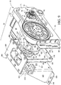
Fig. 9 is an isometric, top view of the drive assembly of the present invention. -
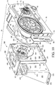
Fig. 10 is an exploded, isometric top view of the drive assembly ofFigure 9 and showing a powering unit separated from an eccentric drive unit. -
Fig. 11 is an isometric, exploded view of the eccentric drive unit as seen inFigure 10 . -
Fig. 12 is an isometric, top side elevation view of the eccentric drive unit. -
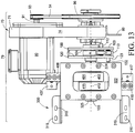
Fig. 13 is a top plan view of the drive assembly as seen inFigure 9 . -
Fig. 14 is an isometric, top view of the stationary base carrying the drive assembly and the counterweight, and showing the relationship of the components to one another. -
Fig. 15 is a partially schematic side elevation view of the improved linear motion conveyor ofFigure 1 and showing the movement of several components of the present invention in phantom lines. - The improved linear motion conveyor of the
present invention 10 generally comprises astationary base 200, adrive assembly 79, aframe assembly 20, acounterweight 40, and anelongated conveyor bed 60. - The improved linear motion conveyor of the present invention is generally indicated by the
numeral 10 inFigs. 1 and following. Theinvention 10 is supported on thestationary base 200 which, in turn, rests upon an underlying supporting surface which is generally indicated by thenumeral 11. The underlying supporting surface may comprise a supporting floor of a factory, or other supporting surface located therebeneath. - The stationary base 200 (
Figures 3 ,3A ) is generally rectilinear in configuration and has afirst end portion 201; asecond end portion 202; afirst side portion 203; asecond side portion 204; atop surface 205; and abottom surface 206. The frame spring mounts 207 (Fig. 3 ) are formed of box beam members and are fixedly attached to thetop surface 205 and are proximate to the first end, orportion 201, and proximate the second end, orportion 202 and extend transversely between thefirst side portion 203, andsecond side portion 204, respectively. A plurality of spaced and generally longitudinally aligned fastener holes are formed in each opposing end portion of the translationframe spring mounts 207, and which receiveconventional fasteners 16. The fasteners secure theframe assembly 20 to thestationary base 200. - Counterweight spring mounts 210 (
Fig. 3 ) are similarly formed of box beam members and which are fixedly attached to thetop surface 205, and located proximate to thefirst end portion 201 and thesecond end portion 202, and inwardly of the translationframe spring mounts 207. These structures extend transversely between thefirst side portion 203 and thesecond side portion 204. A plurality of generally longitudinally aligned fastener holes are formed in each opposing end portion of thecounterweight spring mounts 210, and receiveconventional fasteners 16 which secure thecounterweight 40 to thestationary base 200. A supporting surface orplatform 211, and which includesend caps frame spring mounts 207 and thecounterweight spring mounts 210, respectively. Theend caps spring mounts elongate platform 211 extends between the two spaced apartcounterweight spring mounts 210 and is medially positioned between thefirst side 203 and thesecond side 204. The raised and elongated platform, or supportingsurface 211 provides aplanar surface 214 which carries and supports various subassemblies of thedrive assembly 79 and which will be discussed, below. - A vertical motor mount 215 (
Fig. 3 ) is structurally attached to thestationary base 200, and is spaced from thecounterweight spring mount 210, and fixedly located proximate thesecond end 202. The vertical motor about 215 has alower end 217 which is structurally attached to thetop surface 205 of thestationary base 200; and anupper end 216 which is located distally from thetop surface 205. A plurality of spaced and vertically elongatedholes 218 and a plurality of spaced and horizontallyelongated holes 219 are formed in thevertical motor mount 215. Theelongated holes drive assembly 79 relative to thestationary base 200. As will be discussed, hereinafter the selective positioning of a portion of thedrive assembly 79, relative to thestationary base 200 is effective in determining the frequency of oscillation of theelongated conveyor bed 60, andcounterweight 40, and the resulting direction of movement ofproduct 15 carried on aproduct transporting surface 64 of theelongated conveyor bed 60. (Fig. 1 ). - A pivot axle 220 (
Fig. 3 ) having abox beam sleeve 221, and a disk shapedend cap 222 is carried by thestationary base 200, and located inwardly relative to thecounterweight spring mount 210, and proximate thefirst end 201, and thefirst side 203 respectively. Thepivot axle 220 is generally cylindrical in shape, horizontally oriented, and extends transversely to thestationary base 200 and is partially, axially carried in a channel (not shown) and which is defined by thebox beam sleeve 221. Thepivot axle 220 provides a pivot point for rotational movement of a powering unit 70 (Fig. 9 ), and which is a subassembly of thedrive assembly 79. As noted previously, thestationary base 200 is supported on an underlying supportingsurface 11. A plurality of spaced levelingfeet 209 which communicate with the bottom 206 (Fig. 2 ) of thestationary base 200 provide a means for precisely leveling theinvention 10 in its operating environment. The precise leveling of theinvention 10 is important because inclines, declines, slants and the like of theinvention 10 will affectproduct 15 movement on theproduct transporting surface 64. - The
frame assembly 20 is generally indicated by the numeral 20 (Figs.4 ,5 ) and communicates between thestationary base 200, and theelongated conveyor bed 60. Theframe 20 facilitates substantially parallel movement of theelongated conveyor bed 60 although it is recognized movement of theelongated conveyor bed 60 upon thetranslation frame 20 includes some minor component of vertical movement which is anticipated to be less than approximately 2% of the amount of horizontal movement. Thetranslation frame 20 includes afirst spring leg 21; asecond spring leg 22; athird spring leg 23; and afourth spring leg 25. Each of therespective spring legs stationary base 200, and which is designated by the letter "b" (21b, 22b, 23b, 24b); and an upper/top or second end which is located proximate to theelongated conveyor bed 60, and which is designated by the letter "a" (21a, 22a, 23a, 24a). Each of therespective spring legs respective spring legs elongated conveyor bed 60 during operation. Each of therespective spring legs respective spring legs stationary base 200, and theelongated conveyor bed 60. The length of therespective spring legs top end bottom end elongated conveyor bed 60 in a predetermined spaced relationship above thestationary base 200. Each of therespective spring legs conventional fastener 16. The fasteners pass through the respective spring legs so as to secure therespective spring legs stationary base 200 respectively and to theelongated conveyor bed 60. Reinforcing plates 28 (Fig. 2 ) define fastener holes (not shown) that align with the fastener holes (not shown) and which are formed in the opposing end portions (a, b) of thespring legs stationary base 200. This arrangement also reinforces the spring leg upper/top ends 21a, 22a, 23a, 24a to the transverse spring leg mounts 65, and which are carried on abottom surface 67 of theelongated conveyor bed 60. (Fig. 5 ). The reinforcingplates 28, along withconventional fasteners 16, fixedly "sandwich" therespective spring leg Fig. 5 ), and the frame spring mounts 207. (Fig. 14 ). The interconnection of therespective spring leg elongated conveyor bed 60, and to thestationary base 200 eliminate any "pivotal" interconnection therebetween. The fixed interconnection of therespective spring legs elongated conveyor bed 60, and thestationary frame 200 eliminates the need for bearings at the interconnections, and also reduces wear, and tear and the maintenance which is necessary to support the movableelongated conveyor bed 60. Further, the fixed interconnection of therespective spring legs elongated conveyor bed 60, and thestationary base 200 provides for a substantially continuous tension to be generated as theelongated conveyor bed 60 is moved from afirst position 25, (Figure 15 ) to a second position 26 (Figure 15 ) along alongitudinal axis 63 of theelongated conveyor bed 60. This reciprocal movement imparts predetermined movement to theproduct 15 and which is carried on aproduct supporting surface 64. Further still, the use of therespective spring legs invention 10. The reduction of noise is attributable, at least in part, to the removal of movable/pivotal interconnections (e.g. bearings) which necessarily have some amount of "play" to facilitate movement and which may be exacerbated after periods of use. - The
frame 20, (Fig. 4 ) and more specifically the top ends 21a, 22a, 23a, 24a of thespring legs Fig. 15 ) The course oftravel 30 is defined between a first, or forwardly directedposition 31, (Fig. 15 ) and a second, opposite, and rearwardly locatedposition 32. (Fig. 15 ). As will be discussed in greater detail in this application, theframe 20 is reciprocally moveable along this course oftravel 30 at different velocities in order to achieve the benefits of the present invention. - The
present invention 10 also includes a reciprocally moveable, and elongated conveyor bed which is generally indicated by the numeral 60. Theelongated conveyor bed 60 has afirst end 61, and an oppositesecond end 62. (Fig. 1 ). Still further, theelongated conveyor bed 60 is generally defined by a longitudinal axis which is indicated by the line labeled 63. Theelongated conveyor bed 60 has aproduct transporting surface 64, which is operable to be reciprocally moved in opposite directions, and at varying velocities so as to cause aproduct 15, which is deposited on theproduct transporting surface 64, to move between the opposite first and second ends 61 and 62 in a predetermined manner. The elongated conveyor bed also has a pair of spaced, substantially vertically disposed sidewalls 66 which confine theproduct 15 on theproduct transporting surface 64. Theelongated conveyor bed 60 also has abottom surface 67. (Fig. 4 ). - Mounting brackets 68 (
Fig. 4 ) are carried on thebottom surface 67, and are spacedly arrayed between the first and second ends 61 and 62, and located laterally inwardly relative to the spacedsidewalls 66. As will be recognized by a study ofFigs. 4 and5 , transverse spring leg mounts 65 interconnect with the mountingbrackets 68, and also with the upper/top end portions spring legs conventional fasteners 16, and reinforcingplates 28 to the transverse spring leg mounts 65. This arrangement renders the spring leg mounts irrotatable relative to theelongated conveyor bed 60. As noted previously, the lower/bottom ends 21b, 22b, 23b, 24b of therespective spring legs stationary base 200 and are likewise thereby rendered substantially irrotatable relative to thestationary base 200. - A drive frame 69 (
Fig. 6 ) and which is formed of a plurality of interconnected beams, and struts, is carried on thebottom surface 67 of theelongated conveyor bed 60. Thedrive frame 69 is located in spaced relation relative to thesecond end portion 62, is and generally centrally positioned between the spaced apart sidewalls 66. Thedrive frame 69 carries a generally horizontal inwardly extendingdriver member 12 that interconnects with theeccentric drive unit 300, and which will be discussed in greater detail, hereinafter. Thedrive member 12 has afirst end portion 12a that is proximate a medial portion of theelongated conveyor bed 60, and asecond end portion 12b that is proximate to thesecond end 62. The drive member is formed of a flexible or resilient material which will allow it to flex about its longitudinal axis. - The
present invention 10 includes a counter weight which is generally indicated by the numeral 40, (Figs. 7 ,8 ,14 ) and which is carried in a location which is vertically, below, theelongated conveyor bed 60, and vertically above thedrive assembly 79. Thecounter weight 40 generally comprises aslab weight frame 39; aslab weight 41; andindividual spring legs slab weight frame 39 is generally rectilinear in configuration and has afirst end portion 42; asecond end portion 43; afirst side portion 44; asecond side portion 45; a top 46; a bottom 47; and having adimensional thickness 48. Amedial cavity 41 is defined in the top 46 and releasably carries theslab weight 41a therein. Therespective spring legs respective spring legs spring legs first end 42, andsecond end 43, and in the corners of theslab weight frame 39. The upper/top end portions slab weight frame 39 byconventional fasteners 16, and reinforcingplates 28 as earlier described. Additionally, the lower/bottom end portions stationary base 200 with reinforcingplates 28 andconventional fasteners 16. The fixed attachment of therespective spring legs slab weight frame 39, and to the counterweight spring mounts 210 positionally maintains therespective spring legs respective spring legs counterweight 40 during operation. - The
slab weight 41 which provides various operational features of thepresent invention 10, is here illustrated as being a substantially rectilinear shaped main body having a predetermined weight. However, it will be recognized that other shapes would work with equal success, and the weight of theslab weight 41 may be adjusted by varying thethickness 48 or composition of theslab weight 41 without changing the length and width dimensions thereof, so that theslab weight 41 may be positionally maintained within the cavity (not shown) defined in the top 46 of theslab weight frame 39. - Referring now to
Figs. 7 and8 , adrive frame 53 which is formed of plural interconnected beams and struts is carried on the bottom 47 of theslab weight frame 39. Thedrive frame 53 is located proximate thesecond end 43, and generally centrally between thefirst side 44 and thesecond side 45. Thedrive frame 53 carries aflexible drive member 54 that interconnects with, or is coupled with, theeccentric drive unit 300, and will be discussed in greater detail, hereinafter. Thedrive member 54 has afirst end portion 54a which is located proximate to thefirst end portion 42, and asecond end portion 54b proximate to thesecond end 43. - The
counter weight 40 is moveable along a reciprocal path of travel that is generally indicated by the numeral 56. (Fig. 15 ). The reciprocal path oftravel 56 is defined between a first, forward orientedposition 57, and a second, rearward orientedposition 58. The repeated reciprocal motion of thecounter weight 40 as will be described, hereinafter, provides an assortment of operational characteristics for theelongated conveyor bed 60. - The drive assembly 79 (
Figures 9-13 ) includes various interconnected subassemblies, all of which will be described in detail. Generally speaking, thedrive assembly 79 is supported by thestationary base 200, and is further oriented and operationally coupled in force transmitting relation relative to theelongated conveyor bed 60, and to thecounterweight 40, so as to impart predetermined reciprocal motion to the same to achieve the benefits of thepresent invention 10. The major subassemblies of thedrive assembly 79 are a poweringunit 70; thevertical motor mount 215; thepivot axle 220 which is supported by thestationary base 200; and aneccentric drive unit 300. - The powering
unit 70 generally provides a selectivelyenergizable motor 90, which is mounted on ahousing 71. The powering unit further includes anendless drive belt 94 and adrive wheel 96. As shown inFigure 10 , thehousing 71 is somewhat generally rectilinear in configuration and further has afirst end 72; asecond end 73; a top 74; a bottom 75; a first side 76; and asecond side 77. Thehousing 71 fixedly carries the selectivelyenergizable motor 90 on thesecond side 77. The selectivelyenergizable motor 90 further has anoutput shaft 91 which extends transversely through ashaft orifice 78, and which is defined in thehousing 71 so that theoutput shaft 91 extends transversely through thehousing 71 and perpendicularly outwardly from the first side 76 thereof. - A drive pulley, or
shim 93 is carried on theoutput shaft 92 and frictionally engages theendless drive belt 94 which communicates force to thedrive wheel 96 so as to transfer rotational motion of theoutput shaft 91 thereto. Thedrive wheel 96 is carried on, or positioned on the first side 76 of thehousing 71, and on afirst axle 92. Thefirst axle 71 is journaled in bearings (not shown), and a bearing block (not shown), and is carried by thehousing 71 and is further spaced apart from thedrive pulley 93. Thedrive wheel 96 has a diameter larger than a diameter of thedrive pulley 93 so as to function as a reduction gear. As is known to those who are skilled in the art, varying the diameter of thedrive pulley 93 and/or the diameter of thedrive wheel 96 will vary the rotational ratio of thedrive pulley 93 relative to thedrive wheel 96 so to increase and/or decrease the rotational speed thereof. A pivot axle aperture orhole 82 is defined by thehousing 71, and is located adjacent to thefirst end 72, and the bottom 75. Theaperture 82 extends transversely through thehousing 71. Thepivot axle aperture 82 axially receives thepivot axle 220 and which is carried by thestationary base 200 so that thedrive unit 70 and its attached components may pivot and move along aradial arc 83 relative to thepivot axle 220. (Fig. 15 ). - A mounting
flange 80 is carried at the second end of thehousing 71. The mountingflange 80 defines a plurality of vertically elongatedholes 81 for receiving fasteners (not shown). The fasteners secure the mountingflange 80 to thevertical motor mount 215. The verticallyelongated holes 81 permit thedrive unit 70, and its attached components to be adjustably positioned relative to thevertical motor mount 215, as thedrive unit 70 is pivoted about thepivot axle 220. The pivoting of thedrive unit 70 about thepivot axle 220 causes the poweringunit 70 to move along the radial arc identified as 83. (Fig. 15 ). - Those skilled in the art will recognize that the movement of the powering
unit 70 about theradial arc 83 will add both a vertical component of movement, as well as a horizontal component of movement to the poweringunit 70. This rotational movement has some tendency to reduce any vertical component of movement of theinvention 10 during operation as therespective spring legs - One skilled in the art will recognize that the powering
unit 70 may be rendered selectively moveable along theradial arc 83 by employing any number of other assemblies including all manner of pneumatic or hydraulic pistons, gear drives, jackscrews and the like, and which can be selectively electrically or mechanically controlled so as to achieve the numerous benefits of the present invention. Such a moving means is generally identified aselement 85. (Fig 15 ). - The operable coupling of the
output shaft 91 to thefirst axle 92 may be done by conventional means, that is, by belt, sprocket and chain, or direct coupling to thefirst axle 92 to effect the rotation of thefirst axle 92 in a given rotational direction. Again, the selectivelyenergizable motor 90 may be coupled to suitable electronic controls (not shown) to effect the selective energizing of themotor 90 to initiate and stop the operation of thepresent invention 10, or further to selectively move the poweringunit 70 to given operational locations along theradial arc 83 and which achieves the benefits of the invention which are disclosed. - Referring now to
Fig. 10 , and mounted on the end of thefirst axle 92, and located opposite thedrive plate 96, is afirst drive plate 100 which functions as a first eccentric weight. Thefirst drive wheel 100 has a substantially circularmain body 101 which is defined by aperipheral edge 102. The circularmain body 101 has a first outwardly facingsurface 103; and an opposite, second inwardly facingsurface 104. An axle aperture (not shown) is formed substantially centrally thereof, and is operable to mateingly couple to one end of thefirst axle 92, and which is located opposite to thedrive wheel 96. - The first drive plate 100 (
Figs. 9 ,10 ) has a multiplicity of through holes orapertures 105 which are formed in a given pattern therein. The area of thefirst drive plate 100 which is located opposite the plurality of through holes orapertures 105 defines, in part, an eccentrically weighted region, or portion of thefirst drive plate 100. In a position located opposite to the eccentrically weighted portion, the firsteccentric weight 100 includes acoupling post 112 and which is located near theperipheral edge 102, and which further extends normally outwardly therefrom. Thecoupling post 112 may be positionally adjusted by matingly cooperating with one of the plurality of holes orapertures 105. This arrangement provides further adjustability to theinstant invention 10. Thecoupling post 112 is operable to rotatably engage and cooperate with adrive link 113. Thedrive link 113 has afirst end 114 which rotatably engages or couples to thecoupling post 112, and an oppositesecond end 115 which rotatably couples with asecond drive plate 120 and which is carried by theeccentric drive unit 300, and which is discussed in the paragraphs which follow. - As shown in
Figs. 11 ,12 and13 theeccentric drive unit 300 comprises a generally hollow frame. Theeccentric drive unit 300 has afirst frame member 301; asecond frame member 311; and atop member 322. Thefirst frame member 301 has afirst end 302; asecond end 303; a top 304; a bottom 305; afirst side 306; asecond side 307. Thefirst frame member 301 defines anaxle hole 308 which communicates between thefirst side 306 and thesecond side 307. Aperpendicularly extending flange 309 is carried along the peripheral edge and further defines a plurality ofholes 310 for carrying or receiving fasteners (not shown). These fasteners mount thefirst frame member 301 to thestationary base 200. Thesecond frame member 311 similarly has afirst end 312; asecond end 313; a top 314; a bottom 315; afirst side 316; asecond side 317. Thesecond side member 311 defines anaxle hole 318 which communicates between thefirst side 316, and thesecond side 317. Aperpendicularly extending flange 319 is carried along the peripheral edge and defines a plurality ofholes 310 for carrying or receiving fasteners (not shown) so as to mount thesecond frame member 311 to thestationary base 200. As best seen inFigure 10 , thesecond frame member 311 has a pair of generally triangular shapedsupport legs 320 which individually extend perpendicularly outwardly from thesecond side 317, and from a location near thefirst end 312, and thesecond end 313 so as to provide lateral support when securing theeccentric drive unit 300 to thestationary base 200. Thetop frame member 322 defines a medially orientedorifice 323 and which communicates between thetop portions second frame members top frame member 322 positionally maintains the spaced relationship between the first andsecond frame members channel 321 is maintained or defined therebetween. A bearing (not shown) and which is carried within a bearing block 324 (Fig. 11 ) is carried on thefirst side 306, of thefirst frame member 301. Asimilar bearing block 325 carrying a bearing (not shown) is carried on thesecond side 317 of thesecond frame member 311. The bearings (not shown) within the respective bearing blocks 324, and 325 journal, or rotatably support, asecond axle 133 that extends transversely through the first andsecond members channel 321 which is defined by theframe members second axle 133 carries thesecond drive plate 120 which functions as a second eccentric weight. - As best seen in
Figs. 10 and11 , thesecond drive plate 120 is similar to thefirst drive plate 100, and further includes a circular main body 121 which is defined by aperipheral edge 122. The circular main body 121 has a second inwardly facingsurface 124 which is disposed in predetermined, spaced, substantially parallel relationship relative to the second inwardly facingsurface 104 of thefirst drive plate 100. Still further, the main body 121 is defined by a first, outwardly facingsurface 123. Similar to thefirst drive plate 100, thesecond drive plate 120 includes anaxle aperture 125 which is formed substantially centrally thereof. Similar to that as earlier described, and discussed with respect to thefirst drive plate 100, a multiplicity of throughholes 130 or apertures are formed in the circular main body 121 of thesecond drive plate 120. The multiplicity of throughholes 130 provides a means for forming a weighted eccentric portion. Acoupling post 132 is provided which is mounted on the second inwardly facingsurface 124, and which is further directed, orientated, or extends in a direction towards thefirst drive plate 100. Thecoupling post 132 may be movably positioned within various of the plurality of throughholes 130, as necessary, so as to achieve the objects of thepresent invention 10. Thecoupling post 132 is rotatably coupled to thesecond end 115 of thedrive link 113. As will be recognized, thedrive link 113 couples thefirst drive plate 100 in force transmitting relation relative to thesecond drive plate 120. Thesecond axle 133 has a first, orproximal end 134 which is matingly received in theaxle aperture 125, and which is defined in the second to driveplate 120. Thesecond axle 133 further has a second ordistal end 135 which is rotatably supported in a bearing (not shown) and which is supported in abearing block 325. Thebearing block 325 is carried by thesecond frame member 311 of theeccentric drive unit 300. (Fig. 11 ). - As best illustrated by
Fig 11 , a firsteccentric camming member 400 and a secondeccentric camming member 410 are carried in predetermined, spaced relation along thesecond axle 133, and are further located within thechannel 321. Therespective camming members first frame member 301 and thesecond frame member 311. Thecamming members eccentric body 401, and 411; a center axis 402, and 412; a radially offsetaxle aperture 403, (not shown) to receive thesecond axle 133; a cooperatingbearing annulus drive arm axle apertures 403, (not shown) of eacheccentric camming member bearings coupling members second drive shaft 133 into reciprocal motion of therespective drive arms - As should be understood, the
first drive arm 406 is coupled in force transmitting relation to thedrive member 54 of thecounterweight 40. In this arrangement, the force transmitted by thefirst drive arm 406 is effective in moving the counter-weight 40 along a reciprocal path of travel 56 (Fig. 15 ) so as to effect, at least in part, the motion of theproduct 15 along theproduct transporting surface 64 in a predetermined direction. Additionally, thesecond drive arm 416 is coupled in force transmitting relation to thedrive member 12 of the elongated conveyor bed the 60. In this arrangement, force transmitted by thesecond drive arm 416 is effective in moving theelongated conveyor bed 60 along the reciprocal course oftravel 27 between the first,forward position 25, and the secondrearward position 26. (Fig. 15 ) As will be best recognized by a study ofFigs. 10 and11 , it will be understood that thefirst axle 92 and thesecond axle 133 are disposed in substantially parallel, spaced relation, and further will be oriented in a non-coaxial relationship one relative to the other when the poweringunit 70 moves along with theradial arc 83. (Fig. 15 ). Still further, the first andsecond axles longitudinal axis 63 of theelongated conveyor bed 60. As will be recognized from a study of the drawings, the selective energizing of theelectric motor 90 is effective in causing rotational movement of thefirst axle 92. This rotational motion of thefirst axle 92 is effective for rotating thefirst drive plate 100 in a given direction. The imparted rotational motion of thefirst drive plate 100, in turn, transmits force through thedrive link 113. The force transmitted by thedrive link 113 then imparts rotational movement to thesecond drive plate 120. Again, rotation of thesecond drive plate 120 is effective in causing a corresponding rotation of thesecond axle 133. In this arrangement, the corresponding rotation of thesecond axle 133 transmits force through theeccentric camming members second axle 133. The rotation of thecamming members drive arms first drive arm 406 is effective in causing the counter-weight 40 to move in a reciprocating fashion along the course oftravel 56. Further, the reciprocal force transmitted bydrive arm 416 is effective in causing theelongated conveyor bed 60 to move in a reciprocating fashion along the course oftravel 27. (Fig. 15 ) moreover, the rotation of thecamming members counter weight 40, and reciprocal motion of theelongated conveyor bed 60 is effective so as to effect movement ofproduct 15 along the product transporting surface 64 (Fig. 1 ) in the fashion which will be discussed in greater detail, hereinafter. - Referring now to
Figs. 1 ,2 and15 , theelongated conveyor bed 60 is moveable along a reciprocal path of travel which is generally indicated by the numeral 27. This path of travel is defined between a first,forward position 25, and a secondrearward position 26. In operation, the elongated conveyor bed, as a general matter, does not reciprocate at an equal velocity when moving in the direction of the firstforward position 25, or in the second,rearward position 26. Those familiar in the art of linear conveyors will understand that theelongated conveyor bed 60 when moved in the direction of the firstforward position 25, moves at a velocity and with a displacement which carries theproduct 15 in a forward direction at a first, predetermined speed or velocity. Then, theconveyor bed 60, when reversing direction, and moving in thesecond direction 26, moves at a velocity or speed which is higher than the predetermined first speed. Therefore, theproduct 15 is slowly advanced, and thebed 60 is then moved rapidly backwards so that theproduct 15 shuffles along theproduct transporting surface 64 when moving from one end to the other. It will be understood that the rotation of the pair ofdrive plates eccentrics product 15. This is clearly set forth in the earlier parent patent application. In this regard, theelongated conveyor bed 60 is rendered operable, in a first mode of operation, wherein theproduct 15 moves from thefirst end 61 to thesecond end 62 at a predetermined speed. Further, and in a second mode of operation, theelongated conveyor bed 60 can be rendered operable such that theproduct 15 may move in a direction from thesecond end 62 and towards thefirst end 61. Still further, and in a third possible mode of operation; theelongated conveyor bed 60 can be rendered operable such that theproduct 15 can substantially stop movement once it is located between the first and second ends 61 and 62 respectively of theproduct transporting surface 64. Additionally, it has been discovered that the present invention can moveproduct 15 up an incline which has a pitch of less than about 7 degrees when measured from the horizontal plane. - To effect the several modes of operation of the
elongated conveyor bed 60, the poweringunit 70 which includes the selectively energizableelectric motor 90; thehousing 71; theendless drive belt 94; and thedrive wheel 96 are pivoted on and about thepivot axle 220 which is carried by thestationary base 200 along the radial arc oftravel 83. This arc oftravel 83 is defined by afirst position 87, (Fig. 15 ) and which positions the poweringunit 70 in a given position which effects the first mode of operation of theelongated conveyor bed 60 movingproduct 15 from thefirst end 61 to thesecond end 62. Further, movement of the poweringunit 70 to asecond position 88 along theradial arc 83 is operable to effect the second mode of operation of theelongated conveyor bed 60 movingproduct 15 from thesecond end 62 to thefirst end 61. Still further, and when placed in anintermediate position 89, the poweringunit 70 is operable to effect the third mode of operation of theelongated conveyor bed 60, and whereinproduct 15 remains a generally stationary on theproduct transporting surface 64. Again, as was discussed in the paragraphs above, and once energized, the electricallyenergizable motor 90 is effective in imparting physical force so as to cause a corresponding rotation of thefirst axle 92. Further, the rotation of thefirst axle 92 causes thefirst drive plate 100 to rotate. As earlier discussed, thedrive link 113 is coupled to thefirst drive plate 100 and transmits power or physical force to thesecond drive plate 120 thereby causing the subsequent rotation of thesecond drive plate 120, and thesecond axle 133 which is coupled therewith. The rotation of thesecond axle 133 is effective in causing the reciprocal, and eccentric rotational motion of the respectiveeccentric camming members drive arms drive arm 416, as earlier described, causes force to be transmitted to theelongated conveyor bed 60, and generates reciprocal motion of theelongated conveyor bed 60 along the course oftravel 27. (Fig. 15 ) This reciprocal motion of theelongated conveyor bed 60 takes place along the path oftravel 27, and between the first andsecond positions second axle 133 is effective in causing the reciprocal motion of thecounter weight 40 along the path oftravel 56 between thefirst position 57, and thesecond position 58. This coordinated movement of the various assemblies, as well as the force generated by the rotation of the first andsecond drive plates product 15 to move along theproduct transporting surface 64. As noted in the paragraphs, above, the selective positioning of the poweringunit 70 along theradial arc 83 is effective in causing theelongated conveyor bed 60 to operate in several modes of operation and which provides several novel features for thepresent invention 10. As will be recognized, the rotation of the poweringunit 70 is effective in moving the selectivelyenergizable motor 90 in a direction along thelongitudinal axis 63 of theelongated conveyor bed 60. - The operation of the described embodiment of the
present invention 10 is believed to be readily apparent and is briefly summarized at this point. - The present invention relates to a
linear motion conveyor 10, which, in its broadest aspect, includes anelongated conveyor bed 60 having opposite first and second ends 61 and 62, and alongitudinal axis 63, and wherein theelongated conveyor bed 60 further has aproduct transporting surface 64 which supports aproduct 15 for movement between the first and second ends 61 and 62, respectively of the elongated conveyor bed. Further, and in its broadest aspect, thepresent invention 10 includes adrive assembly 79 which is oriented in predetermined force transmitting relation relative to theelongated conveyor bed 60, and which, when energized, imparts reciprocal motion to theelongated conveyor bed 60 to effect the selective movement of theproduct 15 along theproduct transporting surface 64 in a first direction which extends between the first and second ends 61 and 62 of theproduct transporting surface 64; a second direction which extends from thesecond end 62, to thefirst end 61 of theproduct transporting surface 64; and which further substantially stops the movement of theproduct 15 which is located between the first and second ends 61/62 of theelongated conveyor bed 60, all without de-energizing thedrive assembly 79. - The
drive assembly 79 imparts reciprocal motion to theelongated conveyor bed 60 which has first andsecond movement components Figure 15 ). Thefirst movement component 191 carries theelongated conveyor bed 60 in a first direction, and at a first predetermined speed. Further, thesecond movement component 192 carries theelongated conveyor bed 60 in a second direction, which is opposite to the first direction, and at a second predetermined speed which is faster than the first predetermined speed. This is illustrated inFig.15 by means of thearrows longer length arrow 191, depicts a slower velocity of theelongated conveyor bed 60, and theshorter length arrow 192 depicts a higher velocity of the of theelongated conveyor bed 60 in a direction opposite toarrow 191. In the arrangement as seen in the drawings, theproduct transporting surface 64 is depicted as substantially horizontally oriented. However, in an alternative form of the invention, theproduct transporting surface 64 is non-horizontally oriented, and could be located at an angle of less than about 7 degrees from the horizontal. In the arrangement as seen in the drawings, the improvedlinear motion conveyor 10, as described, and more specifically theelongated conveyor bed 60 thereof reciprocates at a frequency of less than about 325 cycles per minute; achieves an elongated bed displacement of less than about 5 cm; and further has an elongated bed acceleration which is imparted to theproduct 15 being transported of less than about 44,8 m/s2.
Claims (10)
- A linear motion conveyor (10) comprising:an elongated reciprocally moveable conveyor bed (60) having opposite first (61) and second (62) ends and a longitudinal axis, and wherein the elongated conveyor bed (60) further has a product transporting surface (64) which supports a product for selective movement between the first (61) and second (62) ends of the elongated conveyor bed (60); anda drive assembly (79) communicating in force transmitting relation with the elongated conveyor bed (60), the drive assembly having a selectively energizable motor (90) which when energized, imparts reciprocal motion to the elongated conveyor bed (60), so as to effect the selective movement of the product along the product transporting bed in a first direction which extends from the first (61) end to the second (62) end of the product transporting surface (64), in a second direction which extends from the second (62) end to the first (61) end of the product transporting surface (64), and which further substantially stops the movement of the product upon the product transporting surface (64); and wherein the drive assembly (79) is carried on a stationary base (200) which is located vertically below the elongated conveyor bed (60), and the drive assembly (79) further has a powering unit subassembly (70);a frame (20) which is supported by the stationary base (200);a counter-weight (40) carried by the stationary base (200);a drive member (54) operatively communicating between the counterweight (40) and the drive assembly (79) to reciprocally move the counterweight (40) along a course of travel (56);a first drive arm (406) borne by the drive assembly (79), and which extends from the drive assembly (79), and is further drivingly coupled to the counter-weight (40), and wherein force applied by the drive assembly (79) to the first drive arm (406) imparts reciprocal motion to the counter-weight (40);a second drive arm (416) borne by the drive assembly (79) and which extends from the drive assembly (79), and is drivingly coupled to the elongated conveyor bed (60), and wherein force applied by the drive assembly (79) to the second drive arm (416) imparts reciprocal motion to the elongated conveyor bed (60);wherein the selectively energizable motor (90) has an output shaft (91) operatively communicating with a first axle (92) which is mounted below the elongated conveyor bed (60), and in a substantially horizontal orientation and transversely relative to the longitudinal axis (63) of the elongated conveyor bed (60), and wherein the first axle (92) carries a first drive plate (100), and wherein a second axle (133) is located in a substantially parallel, non-coaxial orientation relative to the first axle (92), and wherein the second axle (133) has a first end (134) carrying a second drive plate (120), and an opposite second end (135), and wherein the first and second drive arms (406,416) are eccentrically drivingly coupled to the second axle (133); anda drive link (113) coupling the first drive plate (100), and the second drive plate (120) together, and wherein upon energizing the selectively energizable motor (90) the subsequent rotation of the first drive plate (100) is operable to transmit force through the drive link (113) so as to facilitate a subsequent rotation of the second drive plate (120), and the second axle (133), which is coupled therewith, and wherein the rotation of the second axle (133) imparts eccentric reciprocal force to the first and second drive arms (406, 416) so as to impart predetermined, reciprocal motion of the counter-weight (40), and the elongated conveyor bed (60)characterized in that,the frame (20) has a plurality of spaced spring legs (21, 22, 23, 24) which support the elongated conveyor bed (60) in a predetermined, spaced relation relative to the stationary base (200), and wherein the frame (20) has a first and a second spring leg (23, 24) that movably support the first end (61) of the elongated conveyor bed (60), and a third and fourth spring leg (21, 22) that moveably support the second (62) end of the elongated conveyor bed (60), and wherein each of the aforementioned spring legs (21, 22, 23, 24) have a first end (21b, 22b, 23b, 24b) which is fixedly mounted on the stationary base (200); and an opposite second end (21a, 22a, 23a, 24a) which is fixedly mounted on the elongated conveyor bed (60), and wherein reciprocal movement of the elongated conveyor bed (60) is facilitated by a back-and-forth flexing motion of the plurality of spring legs (21, 22, 23, 24); and in thatthe counter-weight (40) is located vertically, below, the elongated conveyor bed (60), and between the two spring legs (23, 24) supporting the first end (61) of the elongated conveyor bed (60), and the two spring legs (21, 22) supporting the second end (62) of the elongated conveyor bed (60), and wherein the counter-weight (40) has a plurality of spaced spring legs (49, 50, 51, 52) having a first end (49b, 50b, 51b, 52b) which is fixedly attached to the stationary base (200), and a second end (49a, 50a, 51a, 52a) which is fixedly attached to the counterweight (40); and in thatthe powering unit (70) is pivotally moveable about a pivot axle (220) which is carried by the stationary base (200), and along an arcuate path of travel (83), and wherein the pivotal movement of the powering unit (70) determines the selective movement of the product (15) upon the product transporting surface (64); and in thatthe first axle (92) is simultaneously selectively moveable along an arcuate path of travel (83) with the pivotal movement of the powering unit (70) about the pivot axle (220) so as to effect movement of the product (15) in the first and second directions along the product transporting surface (64), and/or to substantially prohibit the movement of the product (15) along the product transporting surface (64).
- A linear motion conveyor as claimed in claim 1, and wherein the elongated conveyor bed (60) has a given weight, and wherein the counter-weight (40) has a weight which is at least about 80% to about 120% of the weight of the elongated conveyor bed (60).
- A linear motion conveyor as claimed in claim 1, and wherein the drive assembly (79) imparts reciprocal motion to the elongated conveyor bed (60) which has a first (191) and second (192) movement components, and wherein the first movement component (191) carries the elongated conveyor bed (60) in a first direction, and at a first predetermined velocity, and wherein the second movement component (192) carries the elongated conveyor bed (60) in a second direction, which is opposite to the first direction, and at a second predetermined velocity which is faster than the first predetermined speed.
- A linear motion conveyor as claimed in claim 3, and wherein the respective first (100) and second (120) drive plates are located in a first predetermined rotational position, one relative to the other to effect the first movement component (191), and in a second, predetermined rotational position (87, 88), one relative to the other, to effect the second movement component (192).
- A linear motion conveyor as claimed in claim 4, and wherein the reciprocal motion of the counter-weight (40) has a first and second movement components (56), and wherein the first movement component (56) of the counter-weight (40) carries the counter-weight (40) in a first direction which is towards the drive assembly (79), and the second movement component (56) of the counter-weight (40) carries the counter-weight (40) in a second direction which is away from the drive assembly (79), and wherein the first movement component (56) of the counter-weight (40) occurs substantially simultaneously as the first movement portion (191) of the elongated conveyor bed (60) carries the elongated conveyor bed (60) in the first direction, and wherein the second movement component (56) of the counter-weight (40) occurs substantially simultaneously when the second movement (192) component of the elongated conveyor bed (60) carries the elongated conveyor bed (60) in the second direction.
- A linear motion conveyor bed as claimed in claim 1, and wherein product transporting surface (64) is substantially horizontally oriented.
- A linear motion conveyor as claimed in claim 1, and wherein the product transporting bed (64) is non-horizontally oriented, and at an angle of not greater than about 7 degrees from the horizontal.
- A linear motion conveyor as claimed in claim 5, and wherein the arcuate path of travel (83) of the first axle (92) moving in unison with the powering unit (79) is less than about 12,7 cm.
- A linear motion conveyor as claimed in claim 5, and wherein the respective first and second drive plates (100, 120) each have a substantially similar weight.
- A linear motion conveyor as claimed in claim 5, and wherein the elongated conveyor bed (60) reciprocates at a frequency of less than about 325 cycles; achieves an elongated bed displacement of less than about 5 cm; and further has an elongated bed acceleration which is imparted to the product (15) being transported of less than about 44,8 m/s2.
Priority Applications (1)
| Application Number | Priority Date | Filing Date | Title |
|---|---|---|---|
| PL16833475T PL3331782T3 (en) | 2015-08-04 | 2016-07-05 | Improved linear motion conveyor |
Applications Claiming Priority (2)
| Application Number | Priority Date | Filing Date | Title |
|---|---|---|---|
| US14/818,129 US9776805B2 (en) | 2013-05-13 | 2015-08-04 | Linear motion conveyor |
| PCT/US2016/040971 WO2017023469A1 (en) | 2015-08-04 | 2016-07-05 | Improved linear motion conveyor |
Publications (3)
| Publication Number | Publication Date |
|---|---|
| EP3331782A1 EP3331782A1 (en) | 2018-06-13 |
| EP3331782A4 EP3331782A4 (en) | 2018-12-19 |
| EP3331782B1 true EP3331782B1 (en) | 2020-12-09 |
Family
ID=57943422
Family Applications (1)
| Application Number | Title | Priority Date | Filing Date |
|---|---|---|---|
| EP16833475.3A Active EP3331782B1 (en) | 2015-08-04 | 2016-07-05 | Improved linear motion conveyor |
Country Status (8)
| Country | Link |
|---|---|
| EP (1) | EP3331782B1 (en) |
| JP (1) | JP6389021B2 (en) |
| AU (1) | AU2016303179B2 (en) |
| CA (1) | CA2993932C (en) |
| ES (1) | ES2850648T3 (en) |
| MX (1) | MX2018001458A (en) |
| PL (1) | PL3331782T3 (en) |
| WO (1) | WO2017023469A1 (en) |
Families Citing this family (4)
| Publication number | Priority date | Publication date | Assignee | Title |
|---|---|---|---|---|
| CN109941683B (en) * | 2019-03-20 | 2023-10-10 | 中铁工程装备集团隧道设备制造有限公司 | Side wall segment conveying device and method |
| EP3947213A4 (en) | 2019-04-05 | 2023-01-04 | Blue Sky Ventures (Ontario) Inc. | VIBRATING CONVEYOR FOR CONVEYING ARTICLES, MACHINE AND RELATED FILLING METHODS |
| CN113581765B (en) * | 2021-06-30 | 2023-05-12 | 深圳市欧盛自动化有限公司 | Jig conveying and positioning mechanism |
| JP7765067B2 (en) * | 2021-08-31 | 2025-11-06 | 株式会社イシダ | Conveyor |
Family Cites Families (8)
| Publication number | Priority date | Publication date | Assignee | Title |
|---|---|---|---|---|
| US2669344A (en) * | 1950-09-23 | 1954-02-16 | Jeffrey Mfg Co | Balanced sectionalized vibratory conveyer |
| US5794757A (en) | 1996-03-15 | 1998-08-18 | Paul A. Svejkovsky | Differential impulse conveyor and method |
| EP2303730B1 (en) * | 2008-06-25 | 2015-06-03 | Brunes, Per | Vibratory conveyor |
| US8066114B2 (en) * | 2010-04-06 | 2011-11-29 | Paul Svejkovsky | Differential impulse conveyor with improved drive |
| US9038815B2 (en) * | 2011-04-27 | 2015-05-26 | Sinfonia Technology Co., Ltd. | Article sorting and conveying device |
| US8561788B2 (en) * | 2011-08-25 | 2013-10-22 | Paul Svejkovsky | Differential impulse conveyor with improved tray |
| JP5739463B2 (en) * | 2013-03-01 | 2015-06-24 | 株式会社ダイシン | Vibrating transfer device |
| US9126765B2 (en) * | 2013-05-13 | 2015-09-08 | Key Technology, Inc. | Linear motion conveyor |
-
2016
- 2016-07-05 CA CA2993932A patent/CA2993932C/en active Active
- 2016-07-05 EP EP16833475.3A patent/EP3331782B1/en active Active
- 2016-07-05 AU AU2016303179A patent/AU2016303179B2/en active Active
- 2016-07-05 WO PCT/US2016/040971 patent/WO2017023469A1/en not_active Ceased
- 2016-07-05 JP JP2018502387A patent/JP6389021B2/en not_active Expired - Fee Related
- 2016-07-05 ES ES16833475T patent/ES2850648T3/en active Active
- 2016-07-05 MX MX2018001458A patent/MX2018001458A/en active IP Right Grant
- 2016-07-05 PL PL16833475T patent/PL3331782T3/en unknown
Non-Patent Citations (1)
| Title |
|---|
| None * |
Also Published As
| Publication number | Publication date |
|---|---|
| EP3331782A4 (en) | 2018-12-19 |
| JP2018521927A (en) | 2018-08-09 |
| EP3331782A1 (en) | 2018-06-13 |
| ES2850648T3 (en) | 2021-08-31 |
| AU2016303179B2 (en) | 2018-08-09 |
| MX2018001458A (en) | 2018-05-17 |
| CA2993932A1 (en) | 2017-02-09 |
| PL3331782T3 (en) | 2021-06-14 |
| CA2993932C (en) | 2019-02-26 |
| AU2016303179A1 (en) | 2018-01-25 |
| JP6389021B2 (en) | 2018-09-12 |
| WO2017023469A1 (en) | 2017-02-09 |
Similar Documents
| Publication | Publication Date | Title |
|---|---|---|
| US9776805B2 (en) | Linear motion conveyor | |
| EP2996971B1 (en) | Linear motion conveyor | |
| CA2993932C (en) | Improved linear motion conveyor | |
| US5178258A (en) | Inertial conveyor system | |
| US4313535A (en) | Excited frame, vibratory conveying apparatus for moving particulate material | |
| DE69933894T2 (en) | ROTATING CONVEYOR WITH LINEAR ENGINE DRIVE | |
| US5335532A (en) | Body maker apparatus | |
| US7216757B1 (en) | Differential motion conveyor | |
| JP2000506482A (en) | Differential impulse conveyor and method | |
| EP2556003B1 (en) | Differential impulse conveyor with improved drive | |
| US6276518B1 (en) | Vibratory drive for a vibratory conveyor | |
| US6298978B1 (en) | Reversing natural frequency vibratory conveyor system | |
| US11577918B2 (en) | Product diverter for a reciprocally movable conveying device | |
| US20180237227A1 (en) | Vertical spiral conveyor | |
| CA2357789C (en) | Rotary drive for vibratory conveyors | |
| US20040251113A1 (en) | Driving mechanism for shaking table | |
| CN114382854A (en) | Mechanical motion mode disc rotating body makes curve reciprocating motion | |
| CN218792959U (en) | Body-building apparatus actuating mechanism and body-building apparatus | |
| CA2432418C (en) | Driving mechanism for shaking table | |
| FI97615B (en) | Process and device for moving the nozzle blocks of the glass-hardening section | |
| GB1602099A (en) | Grading apparatus | |
| JP2007007751A (en) | Cutting machine |
Legal Events
| Date | Code | Title | Description |
|---|---|---|---|
| STAA | Information on the status of an ep patent application or granted ep patent |
Free format text: STATUS: THE INTERNATIONAL PUBLICATION HAS BEEN MADE |
|
| PUAI | Public reference made under article 153(3) epc to a published international application that has entered the european phase |
Free format text: ORIGINAL CODE: 0009012 |
|
| STAA | Information on the status of an ep patent application or granted ep patent |
Free format text: STATUS: REQUEST FOR EXAMINATION WAS MADE |
|
| 17P | Request for examination filed |
Effective date: 20180115 |
|
| AK | Designated contracting states |
Kind code of ref document: A1 Designated state(s): AL AT BE BG CH CY CZ DE DK EE ES FI FR GB GR HR HU IE IS IT LI LT LU LV MC MK MT NL NO PL PT RO RS SE SI SK SM TR |
|
| AX | Request for extension of the european patent |
Extension state: BA ME |
|
| DAV | Request for validation of the european patent (deleted) | ||
| DAX | Request for extension of the european patent (deleted) | ||
| A4 | Supplementary search report drawn up and despatched |
Effective date: 20181116 |
|
| RIC1 | Information provided on ipc code assigned before grant |
Ipc: B65G 27/10 20060101ALI20181112BHEP Ipc: B65G 27/00 20060101ALI20181112BHEP Ipc: B65G 27/20 20060101ALI20181112BHEP Ipc: B65G 27/08 20060101ALI20181112BHEP Ipc: B65G 27/32 20060101AFI20181112BHEP Ipc: B65G 25/04 20060101ALI20181112BHEP |
|
| STAA | Information on the status of an ep patent application or granted ep patent |
Free format text: STATUS: EXAMINATION IS IN PROGRESS |
|
| 17Q | First examination report despatched |
Effective date: 20190830 |
|
| GRAP | Despatch of communication of intention to grant a patent |
Free format text: ORIGINAL CODE: EPIDOSNIGR1 |
|
| STAA | Information on the status of an ep patent application or granted ep patent |
Free format text: STATUS: GRANT OF PATENT IS INTENDED |
|
| INTG | Intention to grant announced |
Effective date: 20200902 |
|
| GRAS | Grant fee paid |
Free format text: ORIGINAL CODE: EPIDOSNIGR3 |
|
| GRAA | (expected) grant |
Free format text: ORIGINAL CODE: 0009210 |
|
| STAA | Information on the status of an ep patent application or granted ep patent |
Free format text: STATUS: THE PATENT HAS BEEN GRANTED |
|
| AK | Designated contracting states |
Kind code of ref document: B1 Designated state(s): AL AT BE BG CH CY CZ DE DK EE ES FI FR GB GR HR HU IE IS IT LI LT LU LV MC MK MT NL NO PL PT RO RS SE SI SK SM TR |
|
| REG | Reference to a national code |
Ref country code: GB Ref legal event code: FG4D |
|
| REG | Reference to a national code |
Ref country code: AT Ref legal event code: REF Ref document number: 1343218 Country of ref document: AT Kind code of ref document: T Effective date: 20201215 Ref country code: CH Ref legal event code: EP |
|
| REG | Reference to a national code |
Ref country code: DE Ref legal event code: R096 Ref document number: 602016049585 Country of ref document: DE |
|
| REG | Reference to a national code |
Ref country code: IE Ref legal event code: FG4D |
|
| REG | Reference to a national code |
Ref country code: NL Ref legal event code: FP |
|
| PG25 | Lapsed in a contracting state [announced via postgrant information from national office to epo] |
Ref country code: RS Free format text: LAPSE BECAUSE OF FAILURE TO SUBMIT A TRANSLATION OF THE DESCRIPTION OR TO PAY THE FEE WITHIN THE PRESCRIBED TIME-LIMIT Effective date: 20201209 Ref country code: NO Free format text: LAPSE BECAUSE OF FAILURE TO SUBMIT A TRANSLATION OF THE DESCRIPTION OR TO PAY THE FEE WITHIN THE PRESCRIBED TIME-LIMIT Effective date: 20210309 Ref country code: GR Free format text: LAPSE BECAUSE OF FAILURE TO SUBMIT A TRANSLATION OF THE DESCRIPTION OR TO PAY THE FEE WITHIN THE PRESCRIBED TIME-LIMIT Effective date: 20210310 Ref country code: FI Free format text: LAPSE BECAUSE OF FAILURE TO SUBMIT A TRANSLATION OF THE DESCRIPTION OR TO PAY THE FEE WITHIN THE PRESCRIBED TIME-LIMIT Effective date: 20201209 |
|
| REG | Reference to a national code |
Ref country code: AT Ref legal event code: MK05 Ref document number: 1343218 Country of ref document: AT Kind code of ref document: T Effective date: 20201209 |
|
| PG25 | Lapsed in a contracting state [announced via postgrant information from national office to epo] |
Ref country code: SE Free format text: LAPSE BECAUSE OF FAILURE TO SUBMIT A TRANSLATION OF THE DESCRIPTION OR TO PAY THE FEE WITHIN THE PRESCRIBED TIME-LIMIT Effective date: 20201209 Ref country code: LV Free format text: LAPSE BECAUSE OF FAILURE TO SUBMIT A TRANSLATION OF THE DESCRIPTION OR TO PAY THE FEE WITHIN THE PRESCRIBED TIME-LIMIT Effective date: 20201209 Ref country code: BG Free format text: LAPSE BECAUSE OF FAILURE TO SUBMIT A TRANSLATION OF THE DESCRIPTION OR TO PAY THE FEE WITHIN THE PRESCRIBED TIME-LIMIT Effective date: 20210309 |
|
| PG25 | Lapsed in a contracting state [announced via postgrant information from national office to epo] |
Ref country code: HR Free format text: LAPSE BECAUSE OF FAILURE TO SUBMIT A TRANSLATION OF THE DESCRIPTION OR TO PAY THE FEE WITHIN THE PRESCRIBED TIME-LIMIT Effective date: 20201209 |
|
| REG | Reference to a national code |
Ref country code: LT Ref legal event code: MG9D |
|
| PG25 | Lapsed in a contracting state [announced via postgrant information from national office to epo] |
Ref country code: CZ Free format text: LAPSE BECAUSE OF FAILURE TO SUBMIT A TRANSLATION OF THE DESCRIPTION OR TO PAY THE FEE WITHIN THE PRESCRIBED TIME-LIMIT Effective date: 20201209 Ref country code: EE Free format text: LAPSE BECAUSE OF FAILURE TO SUBMIT A TRANSLATION OF THE DESCRIPTION OR TO PAY THE FEE WITHIN THE PRESCRIBED TIME-LIMIT Effective date: 20201209 Ref country code: LT Free format text: LAPSE BECAUSE OF FAILURE TO SUBMIT A TRANSLATION OF THE DESCRIPTION OR TO PAY THE FEE WITHIN THE PRESCRIBED TIME-LIMIT Effective date: 20201209 Ref country code: SM Free format text: LAPSE BECAUSE OF FAILURE TO SUBMIT A TRANSLATION OF THE DESCRIPTION OR TO PAY THE FEE WITHIN THE PRESCRIBED TIME-LIMIT Effective date: 20201209 Ref country code: SK Free format text: LAPSE BECAUSE OF FAILURE TO SUBMIT A TRANSLATION OF THE DESCRIPTION OR TO PAY THE FEE WITHIN THE PRESCRIBED TIME-LIMIT Effective date: 20201209 Ref country code: RO Free format text: LAPSE BECAUSE OF FAILURE TO SUBMIT A TRANSLATION OF THE DESCRIPTION OR TO PAY THE FEE WITHIN THE PRESCRIBED TIME-LIMIT Effective date: 20201209 Ref country code: PT Free format text: LAPSE BECAUSE OF FAILURE TO SUBMIT A TRANSLATION OF THE DESCRIPTION OR TO PAY THE FEE WITHIN THE PRESCRIBED TIME-LIMIT Effective date: 20210409 |
|
| PG25 | Lapsed in a contracting state [announced via postgrant information from national office to epo] |
Ref country code: AT Free format text: LAPSE BECAUSE OF FAILURE TO SUBMIT A TRANSLATION OF THE DESCRIPTION OR TO PAY THE FEE WITHIN THE PRESCRIBED TIME-LIMIT Effective date: 20201209 |
|
| REG | Reference to a national code |
Ref country code: ES Ref legal event code: FG2A Ref document number: 2850648 Country of ref document: ES Kind code of ref document: T3 Effective date: 20210831 |
|
| REG | Reference to a national code |
Ref country code: DE Ref legal event code: R097 Ref document number: 602016049585 Country of ref document: DE |
|
| PG25 | Lapsed in a contracting state [announced via postgrant information from national office to epo] |
Ref country code: IS Free format text: LAPSE BECAUSE OF FAILURE TO SUBMIT A TRANSLATION OF THE DESCRIPTION OR TO PAY THE FEE WITHIN THE PRESCRIBED TIME-LIMIT Effective date: 20210409 |
|
| PLBE | No opposition filed within time limit |
Free format text: ORIGINAL CODE: 0009261 |
|
| STAA | Information on the status of an ep patent application or granted ep patent |
Free format text: STATUS: NO OPPOSITION FILED WITHIN TIME LIMIT |
|
| PG25 | Lapsed in a contracting state [announced via postgrant information from national office to epo] |
Ref country code: AL Free format text: LAPSE BECAUSE OF FAILURE TO SUBMIT A TRANSLATION OF THE DESCRIPTION OR TO PAY THE FEE WITHIN THE PRESCRIBED TIME-LIMIT Effective date: 20201209 Ref country code: IT Free format text: LAPSE BECAUSE OF FAILURE TO SUBMIT A TRANSLATION OF THE DESCRIPTION OR TO PAY THE FEE WITHIN THE PRESCRIBED TIME-LIMIT Effective date: 20201209 |
|
| 26N | No opposition filed |
Effective date: 20210910 |
|
| PG25 | Lapsed in a contracting state [announced via postgrant information from national office to epo] |
Ref country code: DK Free format text: LAPSE BECAUSE OF FAILURE TO SUBMIT A TRANSLATION OF THE DESCRIPTION OR TO PAY THE FEE WITHIN THE PRESCRIBED TIME-LIMIT Effective date: 20201209 Ref country code: SI Free format text: LAPSE BECAUSE OF FAILURE TO SUBMIT A TRANSLATION OF THE DESCRIPTION OR TO PAY THE FEE WITHIN THE PRESCRIBED TIME-LIMIT Effective date: 20201209 |
|
| REG | Reference to a national code |
Ref country code: DE Ref legal event code: R119 Ref document number: 602016049585 Country of ref document: DE |
|
| REG | Reference to a national code |
Ref country code: CH Ref legal event code: PL |
|
| PG25 | Lapsed in a contracting state [announced via postgrant information from national office to epo] |
Ref country code: MC Free format text: LAPSE BECAUSE OF FAILURE TO SUBMIT A TRANSLATION OF THE DESCRIPTION OR TO PAY THE FEE WITHIN THE PRESCRIBED TIME-LIMIT Effective date: 20201209 |
|
| PG25 | Lapsed in a contracting state [announced via postgrant information from national office to epo] |
Ref country code: LI Free format text: LAPSE BECAUSE OF NON-PAYMENT OF DUE FEES Effective date: 20210731 Ref country code: DE Free format text: LAPSE BECAUSE OF NON-PAYMENT OF DUE FEES Effective date: 20220201 Ref country code: CH Free format text: LAPSE BECAUSE OF NON-PAYMENT OF DUE FEES Effective date: 20210731 |
|
| PG25 | Lapsed in a contracting state [announced via postgrant information from national office to epo] |
Ref country code: IS Free format text: LAPSE BECAUSE OF FAILURE TO SUBMIT A TRANSLATION OF THE DESCRIPTION OR TO PAY THE FEE WITHIN THE PRESCRIBED TIME-LIMIT Effective date: 20210409 Ref country code: LU Free format text: LAPSE BECAUSE OF NON-PAYMENT OF DUE FEES Effective date: 20210705 |
|
| PG25 | Lapsed in a contracting state [announced via postgrant information from national office to epo] |
Ref country code: IE Free format text: LAPSE BECAUSE OF NON-PAYMENT OF DUE FEES Effective date: 20210705 |
|
| PG25 | Lapsed in a contracting state [announced via postgrant information from national office to epo] |
Ref country code: HU Free format text: LAPSE BECAUSE OF FAILURE TO SUBMIT A TRANSLATION OF THE DESCRIPTION OR TO PAY THE FEE WITHIN THE PRESCRIBED TIME-LIMIT; INVALID AB INITIO Effective date: 20160705 |
|
| PG25 | Lapsed in a contracting state [announced via postgrant information from national office to epo] |
Ref country code: CY Free format text: LAPSE BECAUSE OF FAILURE TO SUBMIT A TRANSLATION OF THE DESCRIPTION OR TO PAY THE FEE WITHIN THE PRESCRIBED TIME-LIMIT Effective date: 20201209 |
|
| PG25 | Lapsed in a contracting state [announced via postgrant information from national office to epo] |
Ref country code: MK Free format text: LAPSE BECAUSE OF FAILURE TO SUBMIT A TRANSLATION OF THE DESCRIPTION OR TO PAY THE FEE WITHIN THE PRESCRIBED TIME-LIMIT Effective date: 20201209 |
|
| PG25 | Lapsed in a contracting state [announced via postgrant information from national office to epo] |
Ref country code: MT Free format text: LAPSE BECAUSE OF FAILURE TO SUBMIT A TRANSLATION OF THE DESCRIPTION OR TO PAY THE FEE WITHIN THE PRESCRIBED TIME-LIMIT Effective date: 20201209 |
|
| PGFP | Annual fee paid to national office [announced via postgrant information from national office to epo] |
Ref country code: PL Payment date: 20250627 Year of fee payment: 10 |
|
| PGFP | Annual fee paid to national office [announced via postgrant information from national office to epo] |
Ref country code: FR Payment date: 20250623 Year of fee payment: 10 |
|
| PGFP | Annual fee paid to national office [announced via postgrant information from national office to epo] |
Ref country code: NL Payment date: 20250723 Year of fee payment: 10 |
|
| PGFP | Annual fee paid to national office [announced via postgrant information from national office to epo] |
Ref country code: ES Payment date: 20250819 Year of fee payment: 10 |
|
| PGFP | Annual fee paid to national office [announced via postgrant information from national office to epo] |
Ref country code: BE Payment date: 20250722 Year of fee payment: 10 Ref country code: GB Payment date: 20250701 Year of fee payment: 10 |
|
| PG25 | Lapsed in a contracting state [announced via postgrant information from national office to epo] |
Ref country code: TR Free format text: LAPSE BECAUSE OF FAILURE TO SUBMIT A TRANSLATION OF THE DESCRIPTION OR TO PAY THE FEE WITHIN THE PRESCRIBED TIME-LIMIT Effective date: 20201209 |