EP3330737B1 - Radar sensor for a vehicle and method for assembling a radar sensor - Google Patents
Radar sensor for a vehicle and method for assembling a radar sensor Download PDFInfo
- Publication number
- EP3330737B1 EP3330737B1 EP17202560.3A EP17202560A EP3330737B1 EP 3330737 B1 EP3330737 B1 EP 3330737B1 EP 17202560 A EP17202560 A EP 17202560A EP 3330737 B1 EP3330737 B1 EP 3330737B1
- Authority
- EP
- European Patent Office
- Prior art keywords
- radar sensor
- circuit board
- radome
- printed circuit
- contact
- Prior art date
- Legal status (The legal status is an assumption and is not a legal conclusion. Google has not performed a legal analysis and makes no representation as to the accuracy of the status listed.)
- Active
Links
- 238000000034 method Methods 0.000 title claims description 7
- 238000009434 installation Methods 0.000 claims description 17
- 239000000463 material Substances 0.000 claims description 13
- 239000000758 substrate Substances 0.000 description 29
- 239000000919 ceramic Substances 0.000 description 28
- 230000002093 peripheral effect Effects 0.000 description 11
- 239000004033 plastic Substances 0.000 description 7
- 239000004020 conductor Substances 0.000 description 6
- 229910052751 metal Inorganic materials 0.000 description 6
- 239000002184 metal Substances 0.000 description 6
- 238000007789 sealing Methods 0.000 description 6
- RNFJDJUURJAICM-UHFFFAOYSA-N 2,2,4,4,6,6-hexaphenoxy-1,3,5-triaza-2$l^{5},4$l^{5},6$l^{5}-triphosphacyclohexa-1,3,5-triene Chemical class N=1P(OC=2C=CC=CC=2)(OC=2C=CC=CC=2)=NP(OC=2C=CC=CC=2)(OC=2C=CC=CC=2)=NP=1(OC=1C=CC=CC=1)OC1=CC=CC=C1 RNFJDJUURJAICM-UHFFFAOYSA-N 0.000 description 3
- 239000006096 absorbing agent Substances 0.000 description 3
- 239000012777 electrically insulating material Substances 0.000 description 3
- 229920001707 polybutylene terephthalate Polymers 0.000 description 3
- 230000036316 preload Effects 0.000 description 3
- 239000004952 Polyamide Substances 0.000 description 2
- 229910052782 aluminium Inorganic materials 0.000 description 2
- XAGFODPZIPBFFR-UHFFFAOYSA-N aluminium Chemical compound [Al] XAGFODPZIPBFFR-UHFFFAOYSA-N 0.000 description 2
- 230000000694 effects Effects 0.000 description 2
- 238000004519 manufacturing process Methods 0.000 description 2
- 229920002647 polyamide Polymers 0.000 description 2
- 238000003825 pressing Methods 0.000 description 2
- 229910000639 Spring steel Inorganic materials 0.000 description 1
- 230000005540 biological transmission Effects 0.000 description 1
- 239000002131 composite material Substances 0.000 description 1
- 230000001066 destructive effect Effects 0.000 description 1
- 238000005553 drilling Methods 0.000 description 1
- 230000005489 elastic deformation Effects 0.000 description 1
- 239000013013 elastic material Substances 0.000 description 1
- 230000005670 electromagnetic radiation Effects 0.000 description 1
- 239000003822 epoxy resin Substances 0.000 description 1
- 238000001125 extrusion Methods 0.000 description 1
- 239000004744 fabric Substances 0.000 description 1
- 239000003063 flame retardant Substances 0.000 description 1
- 239000003365 glass fiber Substances 0.000 description 1
- -1 polybutylene terephthalate Polymers 0.000 description 1
- 229920000647 polyepoxide Polymers 0.000 description 1
- 230000001681 protective effect Effects 0.000 description 1
- 239000000126 substance Substances 0.000 description 1
- 229920001169 thermoplastic Polymers 0.000 description 1
Images

Classifications
-
- G—PHYSICS
- G01—MEASURING; TESTING
- G01S—RADIO DIRECTION-FINDING; RADIO NAVIGATION; DETERMINING DISTANCE OR VELOCITY BY USE OF RADIO WAVES; LOCATING OR PRESENCE-DETECTING BY USE OF THE REFLECTION OR RERADIATION OF RADIO WAVES; ANALOGOUS ARRANGEMENTS USING OTHER WAVES
- G01S13/00—Systems using the reflection or reradiation of radio waves, e.g. radar systems; Analogous systems using reflection or reradiation of waves whose nature or wavelength is irrelevant or unspecified
- G01S13/88—Radar or analogous systems specially adapted for specific applications
- G01S13/93—Radar or analogous systems specially adapted for specific applications for anti-collision purposes
- G01S13/931—Radar or analogous systems specially adapted for specific applications for anti-collision purposes of land vehicles
-
- G—PHYSICS
- G01—MEASURING; TESTING
- G01S—RADIO DIRECTION-FINDING; RADIO NAVIGATION; DETERMINING DISTANCE OR VELOCITY BY USE OF RADIO WAVES; LOCATING OR PRESENCE-DETECTING BY USE OF THE REFLECTION OR RERADIATION OF RADIO WAVES; ANALOGOUS ARRANGEMENTS USING OTHER WAVES
- G01S7/00—Details of systems according to groups G01S13/00, G01S15/00, G01S17/00
- G01S7/02—Details of systems according to groups G01S13/00, G01S15/00, G01S17/00 of systems according to group G01S13/00
- G01S7/027—Constructional details of housings, e.g. form, type, material or ruggedness
-
- H—ELECTRICITY
- H01—ELECTRIC ELEMENTS
- H01Q—ANTENNAS, i.e. RADIO AERIALS
- H01Q1/00—Details of, or arrangements associated with, antennas
- H01Q1/27—Adaptation for use in or on movable bodies
- H01Q1/32—Adaptation for use in or on road or rail vehicles
- H01Q1/3208—Adaptation for use in or on road or rail vehicles characterised by the application wherein the antenna is used
- H01Q1/3233—Adaptation for use in or on road or rail vehicles characterised by the application wherein the antenna is used particular used as part of a sensor or in a security system, e.g. for automotive radar, navigation systems
-
- H—ELECTRICITY
- H01—ELECTRIC ELEMENTS
- H01Q—ANTENNAS, i.e. RADIO AERIALS
- H01Q1/00—Details of, or arrangements associated with, antennas
- H01Q1/42—Housings not intimately mechanically associated with radiating elements, e.g. radome
-
- H—ELECTRICITY
- H01—ELECTRIC ELEMENTS
- H01Q—ANTENNAS, i.e. RADIO AERIALS
- H01Q1/00—Details of, or arrangements associated with, antennas
- H01Q1/52—Means for reducing coupling between antennas; Means for reducing coupling between an antenna and another structure
- H01Q1/526—Electromagnetic shields
-
- H—ELECTRICITY
- H01—ELECTRIC ELEMENTS
- H01Q—ANTENNAS, i.e. RADIO AERIALS
- H01Q17/00—Devices for absorbing waves radiated from an antenna; Combinations of such devices with active antenna elements or systems
Definitions
- the invention relates to a radar sensor for a vehicle, having at least one radar sensor housing in which at least one radar antenna and at least one circuit board is arranged, the radar sensor housing having at least one basic housing part with an installation side on which the at least one radar antenna and the at least one circuit board can be introduced , and has a radome with which the installation side is covered and through which signals transmitted by the at least one radar antenna and / or signals to be received during operation of the radar sensor can pass, wherein the radome has at least one electrical connection element that is inside the radar sensor housing at least has an inner contact section for making electrical contact with the at least one circuit board and outside the radar sensor housing at least one outer contact section for connecting at least one electrical line.
- the invention also relates to a method for assembling a radar sensor for a vehicle, in which at least one radar antenna and at least one printed circuit board are arranged in or on a basic housing part of a radar sensor housing of the radar sensor, a radome is mounted on the basic housing part, the at least one printed circuit board with at least electrical contact is made with an electrical connection element on the radome side, and the radome is fixed to the base housing part, wherein the at least one connection element can be connected to at least one electrical line outside the radar sensor housing.
- the radar device consists of a trough-shaped housing with side walls connected via a housing base and a housing cover.
- a first printed circuit board with high-frequency components and one that is spaced therefrom by means of a resilient shielding device are arranged from the housing added second circuit board with low frequency components.
- the first circuit board is also called a high-frequency circuit board and the second circuit board is also called a low-frequency circuit board.
- the high-frequency circuit board has a radar antenna on the bottom of the housing.
- a plug socket is formed on a transverse side wall, the plug contacts of which are guided into the housing and end there bent at right angles in press-fit pins.
- the invention is based on the object of designing a radar sensor and a method of the type mentioned at the outset in which the radar sensor can be assembled more simply, in particular the at least one electrical connection element can be contacted more easily with the at least one circuit board.
- this object is achieved by the radar sensor according to claim 1 or by the method according to claim 13.
- the electrical contact between the at least one inner contact section and a contact surface on the side of the at least one printed circuit board is realized by pressing the corresponding electrical contact surfaces onto one another. It is not necessary that parts of the at least one inner contact section have to be inserted or pressed into the at least one circuit board, as is the case with the radar device known from the prior art.
- the contact is only ensured on the surface and by mechanical pressure.
- the mechanical pressure can be implemented by a pressing force which is built up in any case when the radar sensor housing is assembled between the radome and the at least one basic housing part. In this way, the at least one inner contact section can be contacted automatically when the at least one base housing part and the radome are assembled.
- surface contacts have the advantage that the contacted at least one printed circuit board only has to be freely accessible on the contacted front side.
- Drilling through the printed circuit board is not necessary according to the invention.
- further components and / or conductor tracks can therefore be arranged on the rear side of the at least one printed circuit board opposite the side contacted.
- the at least one printed circuit board can be made smaller overall. This is particularly advantageous when a plurality of electrical connection elements are provided, since a correspondingly large area would be occupied on the rear side of the circuit board for these with the previously known use of continuous bores for press-in pins.
- the at least one connecting element leads out of the radar sensor housing.
- the at least one connecting element can advantageously be designed outside the radar sensor housing for connecting external signal and / or power supply lines.
- the at least one circuit board can advantageously carry at least one electrical component and / or at least one radar antenna, in particular a substrate with the at least one radar antenna. Furthermore, corresponding electrical lines, in particular in the form of conductor tracks, can be implemented on the at least one printed circuit board.
- the substrate can advantageously be a ceramic substrate.
- the at least one printed circuit board can carry components, in particular for signal processing and / or voltage supply.
- the radar sensor can be equipped with its own signal processing and / or voltage supply.
- At least one in particular electrical / electronic component can be arranged on a surface of the at least one printed circuit board facing away from the at least one radar antenna.
- a space between the at least one radar antenna and the at least one printed circuit board can be kept free or provided with other elements, in particular at least one absorber element.
- the at least one printed circuit board can advantageously be a so-called FR4 printed circuit card.
- Such circuit cards can have a greater mechanical inherent stability in comparison in particular to circuit boards made of hard cardboard known on the market.
- FR4 flame retardant class 4 denotes a class of flame-retardant and flame-retardant composite materials consisting of epoxy resin and glass fiber fabric.
- the radar sensor can advantageously be designed for use in a radar band between 76 GHz and 81 GHz.
- the radar sensor can advantageously be designed for use in what is known as an automotive radar band. In this way, the radar sensor can be used in the automotive sector.
- a radome is a closed protective cover that protects radar antennas from external mechanical and chemical influences such as wind or rain.
- radomes it is known that materials are used which are particularly permeable to radar signals.
- the radar sensor can be used in a vehicle, in particular a motor vehicle.
- the radar sensor can advantageously be used in a land vehicle, in particular a passenger car, truck, bus, motorcycle or the like.
- the radar sensor can also be used in autonomous or at least partially autonomous vehicles.
- the radar sensor can advantageously be connected to or part of at least one electronic control device of a vehicle, in particular a driver assistance system and / or a chassis control and / or a driver information device.
- the object data recorded with the radar sensor in particular the distance, direction and / or relative speed of an object relative to the vehicle, can be transmitted to the control device and used to influence driving functions, in particular the speed, a braking function, a steering function and / or an output an information and / or warning signal, in particular for the driver.
- At least the at least one inner contact section can be elastic at least in sections.
- the electrical contact can be provided with a mechanical elastic preload.
- any component-related and / or assembly-related tolerances can be better compensated.
- any vibrations during operation of the radar sensor, in particular when used in a vehicle can be better compensated for.
- the elasticity of the at least one inner contact section can be realized by choosing a suitable material and / or a suitable shape.
- the at least one inner contact section can advantageously be made of an elastic material or have such a material. Alternatively or additionally, the at least one inner contact section can have a shape which allows elastic deformation. The at least one inner contact section can advantageously have at least one elastically deformable prebend.
- At least the at least one inner contact section can be made of an in particular elastic metal or have such a metal. In this way, elasticity and electrical conductivity can easily be combined.
- the entire at least one connecting element can advantageously be elastic, at least in sections. In this way, the at least one connecting element can be produced more easily.
- At least one electrical connection element can be embedded, at least in sections, directly or indirectly in the material of the radome. At least one electrical connection element can be embedded, at least in sections, directly into the material of the radome. In this way, the at least one electrical connecting element can be embedded directly in the material of the radome during the manufacture of the radome, in particular encapsulated or overmolded with the material of the radome, and thus prefabricated together with it.
- At least one electrical connection element can be embedded indirectly, in particular by means of a holding element, in the material of the radome.
- the at least one electrical connection element can, in particular, be preassembled in the holding element and, together with this, embedded in the material of the radome.
- the at least one inner contact section has at least one bend.
- At least one bend is advantageously convex when viewed from the at least one printed circuit board.
- the contact area of the at least one inner contact section which rests in an electrically conductive manner on a corresponding contact area of the circuit board, can be enlarged.
- the at least one inner contact section can face the basic housing part. In this way, when the radome is arranged on or in the base housing part, the at least one inner contact section can automatically be brought into electrical contact with a corresponding facing contact surface of the at least one circuit board which is arranged in or on the at least one base housing part.
- At least one directional component of the at least one inner contact section and at least one directional component of the corresponding contact surface of the at least one printed circuit board can be directed parallel to an assembly direction of the radome with the at least one basic housing part.
- corresponding assembly forces between the radome and the at least one base housing part can simultaneously increase a contact pressure of the at least one inner contact section against the corresponding contact surface of the at least one circuit board.
- the electrical contact can be improved overall.
- At least one electrical connection element can be arranged at least in sections in a holding element.
- the at least one electrical connection element can be held with the at least one holding element.
- the at least one electrical connection element can be prefabricated with the at least one holding element and then connected to the radome. In this way, a plurality of electrical connecting elements can also be prefabricated in the at least one holding element and more easily connected together with the radome.
- the at least one electrical connection element can advantageously be embedded, in particular cast, in the at least one holding element. In this way, the at least one electrical connection element can be held stably in the at least one holding element.
- the at least one holding element can advantageously be made of an electrically insulating material. In this way, several electrical connecting elements can be arranged and held in an electrically insulated manner from one another.
- the at least one holding element can advantageously be made of plastic.
- the at least one electrical connection element can simply be extrusion-coated or encapsulated with the plastic material during the production of the holding element.
- At least one electrical connection element can be arranged in a circumferential wall of the radome. In this way, the at least one electrical connection element can be arranged in an area where it does not interfere with the reception and / or transmission of radar signals.
- At least one electrical connection element can be designed in one piece with at least one inner contact section and at least one connection section. In this way, a reliable electrical connection between the at least one inner contact section and the at least one connection section can be easily implemented. For this no additional work step is required.
- the at least one electrical connection element outside the radar sensor housing can be designed as part of an electrical quick connection.
- a quick connection can be closed quickly and easily.
- a quick connection can be designed to be non-destructive and detachable.
- the quick connection can advantageously be a plug connection.
- the at least one connecting element can be designed as a plug and / or socket of a plug connection.
- the radar sensor housing has a plurality of elastic clip elements with which the radome can be attached to the at least one basic housing part.
- a mechanical basic tension can be realized with which the at least one inner contact section can be pressed against the at least one contact surface of the at least one circuit board and / or the at least one circuit board can be clamped and fixed.
- the at least one basic housing part can advantageously comprise or consist of metal, in particular aluminum. In this way, a mechanically stable radar sensor housing can be realized.
- the radome can in particular comprise or consist of thermoplastic plastic, in particular polybutylene terephthalate (PBT) and / or polyamide (PA).
- thermoplastic plastic in particular polybutylene terephthalate (PBT) and / or polyamide (PA).
- PBT polybutylene terephthalate
- PA polyamide
- the radome can be transparent to radar signals.
- housing parts made of plastic can give way to pressures acting on them over time. This can be compensated for by the elasticity of the clip elements and / or of the at least one inner contact section.
- the clamp connection can prevent the connection between the at least one base housing part and the radome and / or the contact between the at least an inner contact portion and the at least one circuit board loosens over time.
- the radome can advantageously have at least one clamping element for fixing at least one radar antenna.
- the at least one radar antenna can advantageously be implemented on a carrier element in the form of an in particular plate-shaped ceramic substrate.
- the carrier element can carry at least one electrical / electronic functional component.
- a connection between the radome and the basic housing part can advantageously be designed in such a way that a mechanical preload is provided for clamping the radar antenna. In this way, assembly-related, operational-related and / or component-related tolerances can be better compensated, especially in the area of the radar sensor housing.
- the technical object is achieved according to the invention in the method in that the at least one printed circuit board is electrically contacted during assembly of the radome on the base housing part with at least one inner surface contact section of at least one electrical connection element on the radome side.
- the contacting of the at least one printed circuit board with the at least one electrical connecting element is implemented automatically when the radome is installed and by the contact pressure exerted thereby.
- the contact is made only by means of surface contacts.
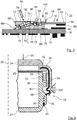
- a radar sensor 10 is shown in different representations.
- the radar sensor 10 can be used, for example, in connection with a driver assistance system of a motor vehicle.
- the radar sensor 10 comprises an openable radar sensor housing 12 in which a ceramic substrate 90 with a radar antenna 14 and a circuit board 16 with components 18 for signal processing and voltage supply are arranged. Furthermore, the radar sensor 10 has a connector 200, which is from the radar sensor housing 12 leads out and can be connected via the corresponding signal lines and power supply lines.
- the radar sensor housing 12 is composed of a basic housing part 22 and a radome 24.
- the basic housing part 22 is made of aluminum, for example.
- the radome 24 is made of plastic, for example PBT.
- the radar sensor housing 12 has approximately the shape of a cuboid.
- the basic housing part 22 and the radome 24 each have the shape of an approximately cuboid trough.
- the radome 24 is placed on an edge of a peripheral wall of the basic housing part 22.
- a circumferential wall 28 of the radome 24 engages around the circumferential wall of the base housing part 22.
- the basic housing part 22 has an installation side 26 with an installation opening.
- the ceramic substrate 90 with the radar antenna 14 and the circuit board 16 can be installed through the installation opening.
- the installation side 26 is openably closed with the radome 24.
- the basic housing part 22, the ceramic substrate 90 with the radar antenna 14, the circuit board 16 and the radome 24 are put together parallel to an imaginary assembly axis 30.
- the radome 24 is fixed to the base housing part 22 by means of a total of four essentially identical clamp connections 32.
- the radome 24 is pressed with the clamp connections 32 parallel to the assembly axis 30 against the edge of the peripheral wall of the base housing part 22.
- the clamp connections 32 are located on opposite longitudinal sides of the radar sensor housing 12. Two of the clamp connections 32 are arranged on the same longitudinal side of the radar sensor housing 12.
- Each clamp connection 32 comprises an elastic clamp element 34 on the side of the radome 24 and a latching lug 36 on the side of the base housing part 22.
- the latching lugs 36 are located on the outer circumferential side of the base housing part 22 and rise radially outward with respect to the assembly axis 30.
- Each of the Latching lugs 36 have a wedge-like bevel 38 on their side facing the installation side 26.
- On the side facing away from the installation side 26, each latching lug 36 has a latching groove 40.
- the clip elements 34 are each elastic spring elements, for example made of spring steel.
- the clamp elements 34 are described below using the clamp element 34 from FIG Figure 4 explained in more detail.
- the clamp element 34 In the area of one of its ends 42, the clamp element 34 has a bend of approximately 90 °. The portion of the clamp element 34 in the region of this bend is embedded in the peripheral wall 28 of the radome 24.
- the clamp element 34 extends in the area of its end 42 in front of the 90 ° bend with respect to the assembly axis 30 radially inward into a cover-side shoulder 48 of the radome 24.
- the clamp element 34 extends on the side of the 90 ° bend facing away from the end 42 roughly parallel to the assembly axis 30.
- the clamp element 34 has an S-shaped bend 44 in its central part running approximately parallel to the assembly axis 30.
- the S-shaped bend 44 is located in an area outside the material of the peripheral wall 28.
- the S-shaped bend 44 is in the assembled state approximately at the level of the wedge-like incline 38 of the corresponding latching lug 36.
- a bent section of the S-shaped bend 44, which faces the peripheral wall 28 of the radome 24, rises towards the peripheral wall of the base housing part 22.
- the clamp element 34 has a latching eye 46 between the S-shaped bend 44 and a free end of the clamp element 34.
- the locking eyelet 46 has the shape of a rectangular window.
- the inner dimensions of the locking lug 46 are somewhat larger than the corresponding outer dimensions of the locking lug 36.
- the locking lug 46 can thus be guided over the locking lug 36 from the outside. In the Figure 4 are indicated by dashed lines for the sake of clarity because of the side boundaries of the locking lug 46 that are actually covered by the locking lug 36.
- the cover-side shoulder 48 forms a rear delimitation of a sealing groove 50, viewed axially to the assembly axis 30 from the radome 24.
- the sealing groove 50 extends circumferentially along the outer circumferential side of the base housing part 22 with respect to the assembly axis 30 and surrounds the installation side 26.
- the sealing groove 50 is delimited at the front by a projection 52 of the base housing part 22.
- the projection 52 extends circumferentially on the outer circumferential side of the base housing part 22 with respect to the assembly axis 30.
- the projection 52 is located between the installation side 26 and the latching lug 36, viewed axially to the assembly axis 30.
- the sealing groove 50 is delimited on its radially inner side with respect to the assembly axis 30 by the peripheral wall of the base housing part 22. On the radially outer side, the sealing groove 50 is delimited by the peripheral wall 28 of the radome 24.
- the circumferential wall 28 overlaps the projection 22.
- the circumferential wall 28 lies with its radially inner circumferential side with respect to the assembly axis 30 on the radially outer circumferential side of the projection 22.
- a seal 54 which is circumferentially connected with respect to the assembly axis 30, is arranged sealingly in the radial direction.
- the radome 24 also has a total of four housing-side clamping elements 56 of a clamping device 58 for clamping the ceramic substrate 90 with the radar antenna 14.
- the housing-side clamping elements 56 are in the Figure 2 , in which the radome 24 is shown transparently for the sake of clarity, and the Figure 3 shown.
- the housing-side clamping elements 56 are arranged on the inner top side of the radome 24 facing the base housing part 22.
- the housing-side clamping elements 56 are each approximately cuboid pedestals which, viewed in the direction of the assembly axis 30, extend away from the top side of the radome 24.
- two of the housing-side clamping elements 56 are located in the area of the same circumferential side of the circumferential wall 28, on which the respective clamp elements 34 are also arranged.
- the clamping elements on the housing side 56 are located approximately between the respective adjacent clamp elements 34.
- the connector 200 is located in a circumferential wall 28 of the radome 24 between the clamp connections 32 there.
- the connector 200 comprises several, for example identical, electrical connection elements 202 in the form of elongated bent metal parts, for example bent metal pins.
- the electrical connecting elements 202 are embedded next to one another in a holding element 204 made of plastic.
- the holding element 204 with the connecting elements 202 is for its part embedded in the material of the radome 24.
- the electrical connecting elements 202 thus lead to the outside through the circumferential wall 28 of the radome 24.
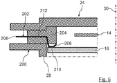
- the connecting elements 202 are described below using one shown in FIG Figure 5 Example shown in more detail.
- the connecting element 202 is constructed in one piece overall.
- the connecting element 202 has an inner contact section 206 and an outer contact section 208.
- the inner contact section 206 is located within the radar sensor housing 12 and is used to make electrical contact with a corresponding contact surface 210, for example a conductor track, on the circuit board 16.
- the inner contact section 206 is designed as a surface contact. The contact is made exclusively on the corresponding surfaces of the inner contact section 206 and the corresponding contact area 210.
- the inner contact section 206 is located on the side of the holding element 204 facing the main housing part 22. On the side facing away from the main housing part 22, the inner contact section 206 is supported by a corresponding section of the holding element 204.
- the inner contact section 206 is curved in a convex manner when viewed from the circuit board 16. It is elastically bendable.
- the inner contact section 206 thus has an elastically deformable pre-bend, with which a mechanical preload and a corresponding tolerance compensation can take place in the direction parallel to the assembly axis 30.
- the contact surfaces 210 of the circuit board 16, on which the corresponding inner contact sections 206 of the connecting elements 202 can abut in an electrically conductive manner, are located on the side of the circuit board 16 on which the radar antenna 14 is also arranged.
- the outer contact section 208 is designed as a plug.
- the outer contact section 208 extends outwardly, for example, transversely to the assembly axis 30.
- the outer contact section 208 can be plugged into a corresponding socket on the signal and / or power supply line for electrical connection.
- the electrical connection elements 202 are each embedded with a holding section 212 between the inner contact section 206 and the outer contact section 208 in the holding element 204.
- the holding sections 212 each extend from the outer contact section 208, initially in the same direction, in order to merge into the respective inner contact section 206 after a bend approximately parallel to the assembly axis 30.
- the circuit board 16 is a so-called FR4 circuit card.
- the circuit board 16 is designed as a rectangular flat plate. In a manner which is not of further interest here, it is fastened in the basic housing 22 in such a way that its opposing surfaces each extend perpendicular to the assembly axis 30.
- the components 18 for signal processing and voltage supply are mounted on the surface of the circuit board 16 facing away from the installation side 26 and are electrically connected to corresponding conductor tracks.
- connection device 62 On the surface of the printed circuit board 16 facing the installation side 26, two elongated connection strips 60 of a connection device 62 are arranged.
- the connection device 62 is used for the mechanical and electrical connection of the ceramic substrate 90 to the radar antenna 14.
- the connection strips 60 run as in FIG Figure 2 shown, parallel to one another and each extend between those circumferential sides of the radar sensor housing 12 on which the respective clamp connections 32 are arranged.
- a section of the circuit board 16 with one of the terminal strips 60 is shown in FIG Figure 3 shown in section.
- the connection strips 60 are mechanically connected to the Circuit board 16 and electrically connected to corresponding conductor tracks of circuit board 16.
- connection strips 60 Between the two connection strips 60 is a in the Figure 3
- the absorber element 64 indicated is fastened flatly on the corresponding surface of the circuit board 16, for example glued on.
- the absorber element 64 serves to dampen electromagnetic radiation.
- connection strips 60 The structure of the two connection strips 60 is essentially identical. In the following, the structure is based on the terminal strip 60 from FIG Figure 3 explained in more detail.
- the terminal strip 60 has an electrical contact device 66 for making electrical contact with corresponding electrical contact areas 68 on the side of the ceramic substrate 90 with the radar antenna 14. Furthermore, the terminal strip 60 comprises a connection-side clamping element 70 of the clamping device 58. In addition, the terminal strip 60 has an elongated connection base body 72, on which the connection-side clamping element 70 is realized in one piece and in which a plurality of electrical contact elements 74 of the contact device 66 are mounted.
- connection base body 72 is made of electrically insulating material. It extends between the circumferential sides of the radar sensor housing 12.
- the connection-side clamping element 70 is located on a longitudinal side facing the other connection strip 60 of the connection device 62 Connection body 72.
- a recess 76 is arranged on the side of the connection-side clamping element 70 facing away from the other connection body 72.
- the recess 76 is open on its side facing away from the circuit board 16. It extends almost over the entire length of the connection base body 72.
- a guide gap 78 is located for the electrical contact elements 78.
- the guide gap 78 extends on the one hand Almost over the entire length of the connection base body 72.
- the guide gap 78 connects a rear side of the connection base body 72 facing away from the other connection strip 60 with the recess 76.
- the guide gap 78 opens on the side facing the circuit board 16.
- a pair of holding rods 80 for positioning and mounting the electrical contact elements 74 is arranged in each case.
- the holding rods 80 extend parallel to one another along the connection base body 72.
- the holding rods 80 are made of electrically insulating material.
- a tool holder 82 leads through the upper side of the platform of the connection base body 62 facing away from the printed circuit board 16.
- the tool holder 82 leads into the guide gap 78.
- the tool holder 82 has the shape of an elongated gap which extends beyond the guide gap 78 in the longitudinal direction.
- the tool holder 82 serves to receive and guide an external tool 84 for actuating the contact elements 74.
- the electrical contact device 66 has a multiplicity of electrical contact elements 74 which are arranged next to one another along the connection base body 72 in the guide gap 78.
- the electrical contact elements 74 are not in electrical contact with one another.
- the contact elements 74 of the exemplary embodiment shown are constructed essentially identically.
- Each contact element 74 consists of an elongated elastic electrical conductor, for example a metal spring.
- the contact elements 74 are based on the in Figure 3 contact element 74 shown in more detail.
- the contact element 74 extends through the two openings of the guide gap 78.
- the contact element 74 is mounted between the corresponding holding rods 80 of the two holding rod pairs.
- the contact element 74 is electrically and mechanically connected to a corresponding electrically conductive area of the circuit board 16, for example by means of a soldered connection.
- the contact element 74 is outside the guide gap 78 equipped with a contact arm 86.
- the contact arm 86 merges into two fork-shaped contact fingers 88.
- the contact fingers 88 encompass an edge of the ceramic substrate 90 on opposite sides viewed in the direction of the assembly axis 30.
- the contact element 74 also has an actuating section 92.
- the actuating section 92 is located between the contact arm 86 and the end of the contact element 74 fastened to the printed circuit board 16.
- the actuating section 92 is arranged within the guide gap 78 in the region of the tool holder 82.
- the tool 84 can act on the actuating section 92 and thus move the contact arm 86 from the contact position I into an assembly position II.
- the assembly position II of the contact arm 86 is in the Figure 3 indicated by dashed lines.
- the contact fingers 88 are bent away from the circuit board 16 in the direction of the installation side 26.
- the fork which is formed by the contact fingers 88, is ready to receive the ceramic substrate 90 in the assembly position II.
- the ceramic substrate 90 has, for example, the shape of a rectangular plate.
- the ceramic substrate 90 is formed from a multilayer ceramic such as LTCC.
- the plate surface of the ceramic substrate 90 facing the installation side 26 of the base housing part 22 forms an emission side 94 for the radar antenna 14.
- the ceramic substrate 90 has corresponding antenna structures not shown in detail in the figures.
- a radar TRX chip 96 is arranged on the rear side of the ceramic substrate 90 and is correspondingly electrical contacted.
- the radar TRX chip 96 has a transmitter and a receiver for corresponding radar signals.
- the radar TRX chip 96 is arranged in the free area between the ceramic substrate 90 and the circuit board 16.
- the radar TRX chip 96 is located between the terminal strips 60.
- the basic housing part 22, the radome 24, the connector 200, the printed circuit board 16 with the connection strips 60 and the ceramic substrate 90 with the radar antenna 14 are each preassembled.
- the circuit board 16 with its side carrying the components 18 is first in an assembly direction 98, which in the Figure 3 is indicated by an arrow, installed parallel to the assembly axis 30 in the basic housing part 22 and fixed there.
- One of the tools 84 is then inserted into the tool receptacles 82 of the two connection strips 60.
- the contact elements 74 are thus moved into their assembly position II against their elastic restoring force.
- the ceramic substrate 90 with the radar antenna 14 is placed with the rear side facing away from the emission side 94 first in the assembly direction 98 between the connection strips 60 such that the respective longitudinal edges come to lie in the forks of the contact fingers 88 of the corresponding contact elements 74.
- the tools 84 are removed from the tool receptacles 82, as a result of which the contact elements 74 move into their respective contact position I due to their elastic restoring force.
- respective electrical contacts are established between the contact fingers 88 and the respective contact areas 68 of the ceramic substrate 90.
- the ceramic substrate 90 rests in the correct installation position on the connection-side clamping elements 70, mounted on opposite sides.
- the radome 24 is plugged onto the base housing part 22 in the assembly direction 98 with the seal 54 interposed.
- the corresponding free ends of the clamp elements 34 are each guided over the wedge-like bevels 38 of the latching lugs 36.
- a locking tool 100 which is in the Figure 4 indicated is, the clamp elements 34 are pressed at their S-shaped bends 44 to the peripheral wall of the base housing part 22, whereby the respective locking eyes 46 slide over the locking lugs 36.
- the clamp elements 34 snap into the corresponding locking grooves 40 of the locking lugs 36 due to the elastic restoring force of the clamp elements 34.
- the inner contact sections 206 of the connecting elements 202 of the connector 200 are automatically connected to the corresponding contact surfaces 210 of the circuit board 16 brought into electrical contact.
- the radome 24 is pressed in the direction of the assembly axis 30 against the edge of the base housing part 22.
- the housing-side clamping elements 56 press against the emission side 94 of the ceramic substrate 90.
- the housing-side clamping elements 56 are each located opposite the corresponding connection-side clamping element 70.
- a clamping force is generated in the Figure 3 indicated by an arrow 102, with which the ceramic substrate 90 and thus the radar antenna 14 are clamped between the housing-side clamping elements 56 and the respective connection-side clamping elements 70.
- the inner contact sections 206 of the connector 200 are pressed against the contact surfaces 210 of the circuit board 16 by the clamping force 102.
- the latches of the clamp connection 32 are released with the aid of the locking tool 100.
- the radome 24 is removed from the basic housing part 22 counter to the assembly direction 98.
- the tools 84 are inserted into the respective tool receptacles 82, so that the contact elements 74 are moved into their assembly position II.
- the ceramic substrate 90 with the radar antenna 14 is then removed against the assembly direction 98.
Description
Die Erfindung betrifft einen Radarsensor für ein Fahrzeug, aufweisend wenigstens ein Radarsensorgehäuse, in dem wenigstens eine Radarantenne und wenigstens eine Leiterplatte angeordnet ist, wobei das Radarsensorgehäuse wenigstens ein Grundgehäuseteil mit einer Einbauseite, auf der die wenigstens eine Radarantenne und die wenigstens eine Leiterplatte eingebracht werden können, und ein Radom aufweist, mit dem die Einbauseite abgedeckt ist und durch welches beim Betrieb des Radarsensors von der wenigstens einen Radarantenne gesendete Signale und/oder zu empfangene Signale hindurch treten können, wobei das Radom wenigstens ein elektrisches Verbindungselement aufweist, das innerhalb des Radarsensorgehäuses wenigstens einen inneren Kontaktabschnitt zur elektrischen Kontaktierung der wenigstens einen Leiterplatte und außerhalb des Radarsensorgehäuses wenigstens einen äußeren Kontaktabschnitt zum Anschluss wenigstens einer elektrischen Leitung aufweist.The invention relates to a radar sensor for a vehicle, having at least one radar sensor housing in which at least one radar antenna and at least one circuit board is arranged, the radar sensor housing having at least one basic housing part with an installation side on which the at least one radar antenna and the at least one circuit board can be introduced , and has a radome with which the installation side is covered and through which signals transmitted by the at least one radar antenna and / or signals to be received during operation of the radar sensor can pass, wherein the radome has at least one electrical connection element that is inside the radar sensor housing at least has an inner contact section for making electrical contact with the at least one circuit board and outside the radar sensor housing at least one outer contact section for connecting at least one electrical line.
Ferner betrifft die Erfindung ein Verfahren zum Zusammenbau eines Radarsensors für ein Fahrzeug, bei dem wenigstens eine Radarantenne und wenigstens eine Leiterplatte in oder an einem Grundgehäuseteil eines Radarsensorgehäuses des Radarsensors angeordnet werden, ein Radom auf das Grundgehäuseteil montiert wird, wobei die wenigstens eine Leiterplatte mit wenigstens einem elektrischen Verbindungselement auf Seiten des Radoms elektrisch kontaktiert wird, und das Radom an dem Grundgehäuseteil fixiert wird, wobei das wenigstens eine Verbindungselement außerhalb des Radarsensorgehäuses mit wenigstens einer elektrischen Leitung verbunden werden kann.The invention also relates to a method for assembling a radar sensor for a vehicle, in which at least one radar antenna and at least one printed circuit board are arranged in or on a basic housing part of a radar sensor housing of the radar sensor, a radome is mounted on the basic housing part, the at least one printed circuit board with at least electrical contact is made with an electrical connection element on the radome side, and the radome is fixed to the base housing part, wherein the at least one connection element can be connected to at least one electrical line outside the radar sensor housing.
Aus der
Der Erfindung liegt die Aufgabe zugrunde, einen Radarsensor und ein Verfahren der eingangs genannten Art gestalten, bei denen der Radarsensor einfacher zusammengebaut, insbesondere das wenigstens eine elektrische Verbindungselement einfacher mit der wenigstens einen Leiterplatte kontaktiert werden kann.The invention is based on the object of designing a radar sensor and a method of the type mentioned at the outset in which the radar sensor can be assembled more simply, in particular the at least one electrical connection element can be contacted more easily with the at least one circuit board.
Diese Aufgabe wird erfindungsgemäß durch den Radarsensor gemäß Anspruch 1, bzw. durch das Verfahren gemäß Anspruch 13 gelöst.According to the invention, this object is achieved by the radar sensor according to claim 1 or by the method according to claim 13.
Erfindungsgemäß wird der elektrische Kontakt zwischen dem wenigstens einen inneren Kontaktabschnitt und einer Kontaktfläche auf Seiten der wenigstens einen Leiterplatte durch das aufeinanderpressen der entsprechenden elektrischen Kontakt-Oberflächen realisiert. Es ist nicht erforderlich, dass Teile des wenigstens einen inneren Kontaktabschnitts in die wenigstens eine Leiterplatte eingesteckt oder eingepresst werden müssen, wie dies bei der aus dem Stand der Technik bekannten Radareinrichtung der Fall ist. Die Kontaktierung wird ausschließlich an der Oberfläche und durch mechanischen Druck sichergestellt. Dabei kann der mechanische Druck durch eine Anpresskraft realisiert werden, welche beim Zusammenbau des Radarsensorgehäuses zwischen dem Radom und dem wenigstens einen Grundgehäuseteil ohnehin aufgebaut wird. Auf diese Weise kann die Kontaktierung des wenigstens einen inneren Kontaktabschnitts automatisch beim Zusammenbau des wenigstens einen Grundgehäuseteils und des Radoms erfolgen.According to the invention, the electrical contact between the at least one inner contact section and a contact surface on the side of the at least one printed circuit board is realized by pressing the corresponding electrical contact surfaces onto one another. It is not necessary that parts of the at least one inner contact section have to be inserted or pressed into the at least one circuit board, as is the case with the radar device known from the prior art. The contact is only ensured on the surface and by mechanical pressure. In this case, the mechanical pressure can be implemented by a pressing force which is built up in any case when the radar sensor housing is assembled between the radome and the at least one basic housing part. In this way, the at least one inner contact section can be contacted automatically when the at least one base housing part and the radome are assembled.
Außerdem haben Oberflächenkontakte den Vorteil, dass die kontaktierte wenigstens eine Leiterplatte lediglich auf der kontaktierten Vorderseite frei zugänglich sein muss.In addition, surface contacts have the advantage that the contacted at least one printed circuit board only has to be freely accessible on the contacted front side.
Ein Durchbohren der Leiterplatte, wie dies zur Realisierung von Eintrittsöffnungen für Einpressstifte üblich, ist erfindungsgemäß nicht erforderlich. Erfindungsgemäß können auf der der kontaktierten Seite gegenüberliegenden Rückseite der wenigstens einen Leiterplatte daher weitere Bauteile und/oder Leiterbahnen angeordnet werden. Auf diese Weise kann die wenigstens eine Leiterplatte insgesamt kleiner ausgestaltet sein. Dies ist besonders vorteilhaft, wenn mehrere elektrische Verbindungselemente vorgesehen sind, da für diese bei der bisher bekannten Verwendung von durchgängigen Bohrungen für Einpressstifte eine entsprechend große Fläche auf der Rückseite der Leiterplatte belegt würden.Drilling through the printed circuit board, as is customary for creating entry openings for press-fit pins, is not necessary according to the invention. According to the invention, further components and / or conductor tracks can therefore be arranged on the rear side of the at least one printed circuit board opposite the side contacted. In this way, the at least one printed circuit board can be made smaller overall. This is particularly advantageous when a plurality of electrical connection elements are provided, since a correspondingly large area would be occupied on the rear side of the circuit board for these with the previously known use of continuous bores for press-in pins.
Das wenigstens eine Verbindungselement führt aus dem Radarsensorgehäuse heraus. Vorteilhafterweise kann das wenigstens eine Verbindungselement außerhalb des Radarsensorgehäuses zum Anschluss von externen Signal- und/oder Stromversorgungsleitungen ausgestaltet sein.The at least one connecting element leads out of the radar sensor housing. The at least one connecting element can advantageously be designed outside the radar sensor housing for connecting external signal and / or power supply lines.
Vorteilhafterweise kann die wenigstens eine Leiterplatte wenigstens ein elektrisches Bauteil und/oder wenigstens eine Radarantenne, insbesondere ein Substrat mit der wenigstens einen Radarantenne, tragen. Ferner können auf der wenigstens einen Leiterplatte entsprechende elektrische Leitungen insbesondere in Form von Leiterbahnen realisiert werden. Bei dem Substrat kann es sich vorteilhafterweise um ein Keramiksubstrat handeln.The at least one circuit board can advantageously carry at least one electrical component and / or at least one radar antenna, in particular a substrate with the at least one radar antenna. Furthermore, corresponding electrical lines, in particular in the form of conductor tracks, can be implemented on the at least one printed circuit board. The substrate can advantageously be a ceramic substrate.
Vorteilhafterweise kann die wenigstens eine Leiterplatte Bauteile insbesondere zur Signalverarbeitung und/oder Spannungsversorgung tragen. Auf diese Weise kann der Radarsensor mit einer eigenen Signalverarbeitung und/oder Spannungsversorgung ausgestattet sein.Advantageously, the at least one printed circuit board can carry components, in particular for signal processing and / or voltage supply. In this way, the radar sensor can be equipped with its own signal processing and / or voltage supply.
Vorteilhafterweise kann wenigstens ein insbesondere elektrisches/elektronisches Bauteil auf einer der wenigstens einen Radarantenne abgewandten Oberfläche der wenigstens einen Leiterplatte angeordnet sein. Auf diese Weise kann ein Raum zwischen der wenigstens einen Radarantenne und der wenigstens einen Leiterplatte freigehalten werden oder mit anderen Elementen, insbesondere wenigstens einem Absorberelement, versehen werden.Advantageously, at least one in particular electrical / electronic component can be arranged on a surface of the at least one printed circuit board facing away from the at least one radar antenna. In this way, a space between the at least one radar antenna and the at least one printed circuit board can be kept free or provided with other elements, in particular at least one absorber element.
Vorteilhafterweise kann die wenigstens eine Leiterplatte eine sogenannte FR4-Leiterkarte sein. Derartige Leiterkarten können eine im Vergleich insbesondere zu marktbekannten Leiterplatten aus Hartpappe größere mechanische Eigenstabilität aufweisen. FR4 (flame retardant class 4) bezeichnet bekanntermaßen eine Klasse von schwer entflammbaren und flammenhemmenden Verbundstoffen bestehend aus Epoxidharz und Glasfasergewebe.The at least one printed circuit board can advantageously be a so-called FR4 printed circuit card. Such circuit cards can have a greater mechanical inherent stability in comparison in particular to circuit boards made of hard cardboard known on the market. As is known, FR4 (flame retardant class 4) denotes a class of flame-retardant and flame-retardant composite materials consisting of epoxy resin and glass fiber fabric.
Vorteilhafterweise kann der Radarsensor zur Verwendung in einem Radarband zwischen 76 GHz und 81 GHz ausgestaltet sein. Vorteilhafterweise kann der Radarsensor zur Verwendung in einem sogenannten Automotive Radarband ausgestaltet sein. Auf diese Weise kann der Radarsensor im Automobilbereich eingesetzt werden.The radar sensor can advantageously be designed for use in a radar band between 76 GHz and 81 GHz. The radar sensor can advantageously be designed for use in what is known as an automotive radar band. In this way, the radar sensor can be used in the automotive sector.
Ein Radom ist bekanntermaßen eine geschlossene Schutzhülle, die Radarantennen vor äußeren mechanischen und chemischen Einflüssen wie Wind oder Regen schützt. Bei Radoms werden bekanntermaßen Materialien verwendet, die für Radarsignale besonders gut durchlässig sind.As is well known, a radome is a closed protective cover that protects radar antennas from external mechanical and chemical influences such as wind or rain. In the case of radomes, it is known that materials are used which are particularly permeable to radar signals.
Der Radarsensor kann bei einem Fahrzeug, insbesondere einem Kraftfahrzeug, verwendet werden. Vorteilhafterweise kann der Radarsensor bei einem Landfahrzeug, insbesondere einem Personenkraftwagen, Lastkraftwagen, einem Bus, einem Motorrad oder dergleichen, verwendet werden. Der Radarsensor kann auch bei autonomen oder wenigstens teilweise autonomen Fahrzeugen eingesetzt werden.The radar sensor can be used in a vehicle, in particular a motor vehicle. The radar sensor can advantageously be used in a land vehicle, in particular a passenger car, truck, bus, motorcycle or the like. The radar sensor can also be used in autonomous or at least partially autonomous vehicles.
Der Radarsensor kann vorteilhafterweise mit wenigstens einer elektronischen Steuervorrichtung eines Fahrzeugs, insbesondere einem Fahrerassistenzsystem und/oder einer Fahrwerksregelung und/oder einer Fahrer-Informationseinrichtung, verbunden oder Teil einer solchen sein. Auf diese Weise können die mit dem Radarsensor erfassten Objektdaten, insbesondere die Entfernung, Richtung und/oder Relativgeschwindigkeit eines Objekts relativ zum Fahrzeug, an die Steuervorrichtung übermittelt und zur Beeinflussung von Fahrfunktionen, insbesondere der Geschwindigkeit, einer Bremsfunktion, einer Lenkungsfunktion und/oder einer Ausgabe eines Hinweis- und/oder Warnsignals insbesondere für den Fahrer, verwendet werden.The radar sensor can advantageously be connected to or part of at least one electronic control device of a vehicle, in particular a driver assistance system and / or a chassis control and / or a driver information device. In this way, the object data recorded with the radar sensor, in particular the distance, direction and / or relative speed of an object relative to the vehicle, can be transmitted to the control device and used to influence driving functions, in particular the speed, a braking function, a steering function and / or an output an information and / or warning signal, in particular for the driver.
Bei einer vorteilhaften Ausführungsform kann wenigstens der wenigstens eine innere Kontaktabschnitt wenigstens abschnittsweise elastisch sein. Auf diese Weise kann die elektrische Kontaktierung mit einer mechanischen elastischen Vorspannung belegt werden. So können etwaige bauteilbedingte und/oder montagebedingte Toleranzen besser ausgeglichen werden. Außerdem können so etwaige Vibrationen beim Betrieb des Radarsensors insbesondere bei der Verwendung in einem Fahrzeug besser kompensiert werden.In an advantageous embodiment, at least the at least one inner contact section can be elastic at least in sections. In this way, the electrical contact can be provided with a mechanical elastic preload. In this way, any component-related and / or assembly-related tolerances can be better compensated. In addition, any vibrations during operation of the radar sensor, in particular when used in a vehicle, can be better compensated for.
Die Elastizität des wenigstens einen inneren Kontaktabschnitts kann durch Wahl eines geeigneten Materials und/oder einer geeigneten Form realisiert werden.The elasticity of the at least one inner contact section can be realized by choosing a suitable material and / or a suitable shape.
Vorteilhafterweise kann der wenigstens eine innere Kontaktabschnitt aus einem elastischen Material sein oder ein derartiges Material aufweisen. Alternativ oder zusätzlich kann der wenigstens eine innere Kontaktabschnitt eine Form aufweisen, welche eine elastische Verformung zulässt. Vorteilhafterweise kann der wenigstens eine innere Kontaktabschnitt wenigstens eine elastisch verformbare Vorbiegung aufweisen.The at least one inner contact section can advantageously be made of an elastic material or have such a material. Alternatively or additionally, the at least one inner contact section can have a shape which allows elastic deformation. The at least one inner contact section can advantageously have at least one elastically deformable prebend.
Vorteilhafterweise kann wenigstens der wenigstens eine innere Kontaktabschnitt aus einem insbesondere elastischen Metall sein oder ein derartiges Metall aufweisen. Auf diese Weise können Elastizität und elektrischen Leitfähigkeit einfach kombiniert werden.Advantageously, at least the at least one inner contact section can be made of an in particular elastic metal or have such a metal. In this way, elasticity and electrical conductivity can easily be combined.
Vorteilhafterweise kann das gesamte wenigstens eine Verbindungselement wenigstens abschnittsweise elastisch sein. Auf diese Weise kann das wenigstens eine Verbindungselement einfacher hergestellt werden.The entire at least one connecting element can advantageously be elastic, at least in sections. In this way, the at least one connecting element can be produced more easily.
Bei einer weiteren vorteilhaften Ausführungsform kann wenigstens ein elektrisches Verbindungselement wenigstens abschnittsweise direkt oder indirekt in das Material des Radoms eingebettet sein. Wenigstens ein elektrisches Verbindungselement kann wenigstens abschnittsweise direkt in das Material des Radoms eingebettet sein. Auf diese Weise kann das wenigstens eine elektrische Verbindungselement direkt bei der Herstellung des Radoms in das Material des Radoms eingebettet, insbesondere mit dem Material des Radoms umgossen oder umspritzt, und so mit diesem gemeinsam vorgefertigt werden.In a further advantageous embodiment, at least one electrical connection element can be embedded, at least in sections, directly or indirectly in the material of the radome. At least one electrical connection element can be embedded, at least in sections, directly into the material of the radome. In this way, the at least one electrical connecting element can be embedded directly in the material of the radome during the manufacture of the radome, in particular encapsulated or overmolded with the material of the radome, and thus prefabricated together with it.
Alternativ oder zusätzlich kann wenigstens ein elektrisches Verbindungselement indirekt, insbesondere mittels einem Halteelement, in das Material des Radoms eingebettet sein. Auf diese Weise kann das wenigstens eine elektrische Verbindungselement insbesondere in dem Halteelement vormontiert und gemeinsam mit diesem in das Material des Radoms eingebettet werden.Alternatively or additionally, at least one electrical connection element can be embedded indirectly, in particular by means of a holding element, in the material of the radome. In this way, the at least one electrical connection element can, in particular, be preassembled in the holding element and, together with this, embedded in the material of the radome.
Erfindungsgemäß weist der wenigstens eine innere Kontaktabschnitt wenigstens eine Biegung auf. Auf diese Weise kann insbesondere in Kombination mit einer elastischen Ausbildung des wenigstens einen inneren Kontaktabschnitts eine flexiblere und zuverlässigere elektrische Kontaktierung erreicht werden. Vorteilhafterweise ist wenigstens eine Biegung von der wenigstens einen Leiterplatte aus betrachtet konvex. Auf diese Weise kann bei einer Erhöhung des Anpressdrucks und einem entsprechenden elastischen Nachgeben des wenigstens einen inneren Kontaktabschnitts die Kontaktfläche des wenigstens einen inneren Kontaktabschnitts, welche an einer entsprechenden Kontaktfläche der Leiterplatte elektrisch leitend anliegt, vergrößert werden.According to the invention, the at least one inner contact section has at least one bend. In this way, in particular in combination with an elastic design of the at least one inner contact section, a more flexible and more reliable electrical contact can be achieved. At least one bend is advantageously convex when viewed from the at least one printed circuit board. In this way, with an increase in the contact pressure and a corresponding elastic yield of the at least one inner contact section, the contact area of the at least one inner contact section, which rests in an electrically conductive manner on a corresponding contact area of the circuit board, can be enlarged.
Bei einer weiteren vorteilhaften Ausführungsform kann der wenigstens eine innere Kontaktabschnitt dem Grundgehäuseteil zugewandt sein. Auf diese Weise kann der wenigstens eine innere Kontaktabschnitt beim anordnen des Radoms an oder in dem Grundgehäuseteil mit einer entsprechenden zugewandten Kontaktfläche der wenigstens einen Leiterplatte, welche in oder an dem wenigstens ein Grundgehäuseteil angeordnet ist, automatisch in elektrischen Kontakt gebracht werden.In a further advantageous embodiment, the at least one inner contact section can face the basic housing part. In this way, when the radome is arranged on or in the base housing part, the at least one inner contact section can automatically be brought into electrical contact with a corresponding facing contact surface of the at least one circuit board which is arranged in or on the at least one base housing part.
Vorteilhafterweise können wenigstens eine Richtungskomponente des wenigstens einen inneren Kontaktabschnitts und wenigstens eine Richtungskomponente der entsprechenden Kontaktfläche der wenigstens einen Leiterplatte parallel zu einer Zusammenbaurichtung des Radoms mit dem wenigstens einen Grundgehäuseteil gerichtet sein. Auf diese Weise können entsprechende Montagekräfte zwischen dem Radom und dem wenigstens ein Grundgehäuseteil zugleich einen Anpressdruck des wenigstens einen inneren Kontaktabschnitts gegen die entsprechende Kontaktfläche der wenigstens einen Leiterplatte vergrößern. Auf diese Weise kann der elektrische Kontakt insgesamt verbessert werden.Advantageously, at least one directional component of the at least one inner contact section and at least one directional component of the corresponding contact surface of the at least one printed circuit board can be directed parallel to an assembly direction of the radome with the at least one basic housing part. In this way, corresponding assembly forces between the radome and the at least one base housing part can simultaneously increase a contact pressure of the at least one inner contact section against the corresponding contact surface of the at least one circuit board. In this way, the electrical contact can be improved overall.
Bei einer weiteren vorteilhaften Ausführungsform kann wenigstens ein elektrisches Verbindungselement wenigstens abschnittsweise in einem Halteelement angeordnet sein. Mit dem wenigstens einen Halteelement kann das wenigstens eine elektrische Verbindungselement gehalten werden. Das wenigstens eine elektrische Verbindungselement kann mit dem wenigstens einen Halteelement vorgefertigt und anschließend mit dem Radom verbunden werden. Auf diese Weise können auch mehrere elektrische Verbindungselemente in dem wenigstens einen Halteelement vorgefertigt und einfacher gemeinsam mit dem Radom verbunden werden.In a further advantageous embodiment, at least one electrical connection element can be arranged at least in sections in a holding element. The at least one electrical connection element can be held with the at least one holding element. The at least one electrical connection element can be prefabricated with the at least one holding element and then connected to the radome. In this way, a plurality of electrical connecting elements can also be prefabricated in the at least one holding element and more easily connected together with the radome.
Vorteilhafterweise kann das wenigstens eine elektrische Verbindungselement in dem wenigstens einen Halteelement eingebettet, insbesondere eingegossen, sein. Auf diese Weise kann das wenigstens eine elektrische Verbindungselement stabil in dem wenigstens einen Halteelement gehalten werden.The at least one electrical connection element can advantageously be embedded, in particular cast, in the at least one holding element. In this way, the at least one electrical connection element can be held stably in the at least one holding element.
Vorteilhafterweise kann das wenigstens eine Halteelement aus einem elektrisch isolierenden Material sein. Auf diese Weise können mehrere elektrische Verbindungselemente gegeneinander elektrisch isoliert angeordnet und gehalten werden.The at least one holding element can advantageously be made of an electrically insulating material. In this way, several electrical connecting elements can be arranged and held in an electrically insulated manner from one another.
Vorteilhafterweise kann das wenigstens eine Halteelement aus Kunststoff sein. Auf diese Weise kann das wenigstens eine elektrische Verbindungselement einfach bei der Herstellung des Halteelements mit dem Kunststoffmaterial umspritzt oder umgossen werden.The at least one holding element can advantageously be made of plastic. In this way, the at least one electrical connection element can simply be extrusion-coated or encapsulated with the plastic material during the production of the holding element.
Bei einer weiteren vorteilhaften Ausführungsform kann wenigstens ein elektrisches Verbindungselement in einer Umfangswand des Radoms angeordnet sein. Auf diese Weise kann das wenigstens eine elektrische Verbindungselement in einem Bereich angeordnet sein, wo es den Empfang und/oder das Senden von Radarsignalen nicht stört.In a further advantageous embodiment, at least one electrical connection element can be arranged in a circumferential wall of the radome. In this way, the at least one electrical connection element can be arranged in an area where it does not interfere with the reception and / or transmission of radar signals.
Bei einer weiteren vorteilhaften Ausführungsform kann wenigstens ein elektrisches Verbindungselement mit wenigstens einem inneren Kontaktabschnitt und wenigstens einem Anschlussabschnitt einteilig ausgestaltet sein. Auf diese Weise kann eine zuverlässige elektrische Verbindung zwischen dem wenigstens einen inneren Kontaktabschnitt und dem wenigstens einen Anschlussabschnitt einfach realisiert werden. Hierzu ist kein zusätzlicher Arbeitsschritt erforderlich.In a further advantageous embodiment, at least one electrical connection element can be designed in one piece with at least one inner contact section and at least one connection section. In this way, a reliable electrical connection between the at least one inner contact section and the at least one connection section can be easily implemented. For this no additional work step is required.
Bei einer weiteren vorteilhaften Ausführungsform kann das wenigstens ein elektrisches Verbindungselement außerhalb des Radarsensorgehäuses als Teil einer elektrischen Schnellverbindung ausgestaltet sein. Eine Schnellverbindung kann schnell und einfach geschlossen werden. Außerdem kann eine Schnellverbindung zerstörungsfrei lösbar ausgestaltet sein. Bei der Schnellverbindung kann es sich vorteilhafterweise um eine Steckverbindung handeln. Das wenigstens eine Verbindungselement kann als Stecker und/oder Buchse einer Steckverbindung ausgestaltet sein.In a further advantageous embodiment, the at least one electrical connection element outside the radar sensor housing can be designed as part of an electrical quick connection. A quick connection can be closed quickly and easily. In addition, a quick connection can be designed to be non-destructive and detachable. The quick connection can advantageously be a plug connection. The at least one connecting element can be designed as a plug and / or socket of a plug connection.
Erfindungsgemäß weist das Radarsensorgehäuse eine Mehrzahl von elastischen Klammerelementen auf, mit denen das Radom an dem wenigstens einen Grundgehäuseteil befestigt werden kann. Mithilfe der elastischen Klammerelemente kann eine mechanische Grundspannung realisiert werden, mit welcher der wenigstens eine innere Kontaktabschnitt gegen die wenigstens eine Kontaktfläche der wenigstens einen Leiterplatte gepresst und/oder die wenigstens eine Leiterplatte festgeklemmt und fixiert werden kann.According to the invention, the radar sensor housing has a plurality of elastic clip elements with which the radome can be attached to the at least one basic housing part. With the aid of the elastic clamp elements, a mechanical basic tension can be realized with which the at least one inner contact section can be pressed against the at least one contact surface of the at least one circuit board and / or the at least one circuit board can be clamped and fixed.
Vorteilhafterweise kann das wenigstens eine Grundgehäuseteil Metall, insbesondere Aluminium, aufweisen oder daraus bestehen. Auf diese Weise kann ein mechanisch stabiles Radarsensorgehäuse realisiert werden.The at least one basic housing part can advantageously comprise or consist of metal, in particular aluminum. In this way, a mechanically stable radar sensor housing can be realized.
Vorteilhafterweise kann das Radom insbesondere thermoplastischen Kunststoff, insbesondere Polybutylenterephthalat (PBT) und/oder Polyamid (PA), aufweisen oder daraus bestehen. Auf diese Weise kann das Radom für Radarsignale durchlässig sein. Es ist insbesondere nicht erforderlich, dass sowohl das wenigstens eine Grundgehäuseteil als auch das Radom aus Kunststoff bestehen. Bekanntermaßen können Gehäuseteile aus Kunststoff mit der Zeit auf sie einwirkenden Drücken nachgeben. Durch die Elastizität der Klammerelemente und/oder des wenigstens einen inneren Kontaktabschnitts kann dies kompensiert werden. So kann auch bei einer Verbindung von Gehäuseteilen, insbesondere einem Radom und/oder einem Grundgehäuseteil, aus Kunststoff über die Lebensdauer ein konstanter Druck aufrechterhalten werden. Mit der Klammerverbindung kann verhindert werden, dass sich die Verbindung zwischen dem wenigstens einen Grundgehäuseteil und dem Radom und/oder die Kontaktierung zwischen dem wenigstens einen inneren Kontaktabschnitt und der wenigstens einen Leiterplatte mit der Zeit lockert.Advantageously, the radome can in particular comprise or consist of thermoplastic plastic, in particular polybutylene terephthalate (PBT) and / or polyamide (PA). In this way, the radome can be transparent to radar signals. In particular, it is not necessary for both the at least one basic housing part and the radome to be made of plastic. It is known that housing parts made of plastic can give way to pressures acting on them over time. This can be compensated for by the elasticity of the clip elements and / or of the at least one inner contact section. Thus, even with a connection of housing parts, in particular a radome and / or a base housing part, made of plastic, a constant pressure can be maintained over the service life. The clamp connection can prevent the connection between the at least one base housing part and the radome and / or the contact between the at least an inner contact portion and the at least one circuit board loosens over time.
Vorteilhafterweise kann das Radom wenigstens ein Klemmelement zum Fixieren wenigstens einer Radarantenne aufweisen.The radome can advantageously have at least one clamping element for fixing at least one radar antenna.
Vorteilhafterweise kann die wenigstens eine Radarantenne auf einem Trägerelement in Form eines insbesondere plattenförmigen Keramiksubstrats realisiert sein. Das Trägerelement kann wenigstens ein elektrisches/elektronisches Funktionsbauteil tragen.The at least one radar antenna can advantageously be implemented on a carrier element in the form of an in particular plate-shaped ceramic substrate. The carrier element can carry at least one electrical / electronic functional component.
Vorteilhafterweise kann eine Verbindung des Radoms mit dem Grundgehäuseteil so ausgestaltet sein, dass eine mechanische Vorspannung zum Festklemmen der Radarantenne bereitstellt gestellt wird. Auf diese Weise können montagebedingte, betriebsbedingte und/oder bauteilbedingte Toleranzen insbesondere im Bereich des Radarsensorgehäuses besser kompensiert werden.A connection between the radome and the basic housing part can advantageously be designed in such a way that a mechanical preload is provided for clamping the radar antenna. In this way, assembly-related, operational-related and / or component-related tolerances can be better compensated, especially in the area of the radar sensor housing.
Ferner wird die technische Aufgabe erfindungsgemäß bei dem Verfahren dadurch gelöst, dass die wenigstens eine Leiterplatte bei der Montage des Radoms auf das Grundgehäuseteil mit wenigstens einem inneren Oberflächen-Kontaktabschnitt wenigstens eines elektrischen Verbindungselements auf Seiten des Radoms elektrisch kontaktiert wird.Furthermore, the technical object is achieved according to the invention in the method in that the at least one printed circuit board is electrically contacted during assembly of the radome on the base housing part with at least one inner surface contact section of at least one electrical connection element on the radome side.
Erfindungsgemäß wird die Kontaktierung der wenigstens einen Leiterplatte mit dem wenigstens einen elektrischen Verbindungselement automatisch beim montieren des Radoms und durch den dadurch ausgeübten Anpressdruck realisiert. Die Kontaktierung erfolgt dabei lediglich mittels Oberflächenkontakten.According to the invention, the contacting of the at least one printed circuit board with the at least one electrical connecting element is implemented automatically when the radome is installed and by the contact pressure exerted thereby. The contact is made only by means of surface contacts.
Im Übrigen gelten die im Zusammenhang mit dem erfindungsgemäßen Radarsensor und dem erfindungsgemäßen Verfahren und deren jeweiligen vorteilhaften Ausgestaltungen aufgezeigten Merkmale und Vorteile untereinander entsprechend und umgekehrt. Die einzelnen Merkmale und Vorteile können selbstverständlich untereinander kombiniert werden, wobei sich weitere vorteilhafte Wirkungen einstellen können, die über die Summe der Einzelwirkungen hinausgehen.In addition, the features and advantages shown in connection with the radar sensor according to the invention and the method according to the invention and their respective advantageous configurations apply mutatis mutandis and vice versa. The individual features and advantages can of course be combined with one another, whereby further advantageous effects can arise that go beyond the sum of the individual effects.
Weitere Vorteile, Merkmale und Einzelheiten der Erfindung ergeben sich aus der nachfolgenden Beschreibung, in der ein Ausführungsbeispiel der Erfindung anhand der Zeichnung näher erläutert wird. Der Fachmann wird die in der Zeichnung, der Beschreibung und den Ansprüchen in Kombination offenbarten Merkmale zweckmäßigerweise auch einzeln betrachten und zu sinnvollen weiteren Kombinationen zusammenfassen.Further advantages, features and details of the invention emerge from the following description, in which an exemplary embodiment of the invention is explained in more detail with reference to the drawing. The person skilled in the art will expediently consider the features disclosed in combination in the drawing, the description and the claims also individually and combine them into meaningful further combinations.
Es zeigen schematisch
- Figur 1
- eine isometrische Darstellung eines Radarsensors mit einem Radarsensorgehäuse, in dem eine Radarantenne und eine Leiterplatte des Radarsensors angeordnet sind;
- Figur 2
- eine Draufsicht auf den Radarsensor der
Figur 1 , wobei das Radom transparent gezeigt ist; - Figur 3
- einen Schnitt durch die Leiterplatte und das Keramiksubstrat mit der Radarantenne des Radarsensors aus den
Figuren 1 und 2 im Bereich einer Anschlussleiste; - Figur 4
- einen Schnitt durch das Radarsensorgehäuse des Radarsensors aus den
Figuren 1 und 2 im Bereich einer Klemmverbindung zwischen dem Radom und einem Grundgehäuseteil; - Figur 5
- einen Schnitt durch einen Teil des Radoms des Radarsensors aus den
Figuren 1 und 2 , in dem ein elektrischer Verbindungsstecker angeordnet ist, mit dem die Leiterplatte kontaktiert wird und der nach außen führt.
- Figure 1
- an isometric view of a radar sensor with a radar sensor housing in which a radar antenna and a circuit board of the radar sensor are arranged;
- Figure 2
- a plan view of the radar sensor of
Figure 1 with the radome shown transparent; - Figure 3
- a section through the circuit board and the ceramic substrate with the radar antenna of the radar sensor from the
Figures 1 and 2 in the area of a terminal strip; - Figure 4
- a section through the radar sensor housing of the radar sensor from the
Figures 1 and 2 in the area of a clamp connection between the radome and a base housing part; - Figure 5
- a section through part of the radome of the radar sensor from the
Figures 1 and 2 , in which an electrical connector is arranged, with which the circuit board is contacted and which leads to the outside.
In den Figuren sind gleiche Bauteile mit gleichen Bezugszeichen versehen.In the figures, the same components are provided with the same reference symbols.
In den
Der Radarsensor 10 umfasst ein öffenbares Radarsensorgehäuse 12, in dem ein Keramiksubstrat 90 mit einer Radarantenne 14 und eine Leiterplatte 16 mit Bauteilen 18 zur Signalverarbeitung und Spannungsversorgung angeordnet sind. Ferner verfügt der Radarsensor 10 über einen Verbindungsstecker 200, welcher aus dem Radarsensorgehäuse 12 herausführt und über den entsprechende Signalleitungen und Stromversorgungsleitungen angeschlossen werden können.The
Das Radarsensorgehäuse 12 ist aus einem Grundgehäuseteil 22 und einem Radom 24 zusammengesetzt. Das Grundgehäuseteil 22 ist beispielsweise aus Aluminium. Das Radom 24 ist aus Kunststoff, beispielsweise PBT.The
Das Radarsensorgehäuse 12 hat insgesamt etwa die Form eines Quaders. Dabei haben das Grundgehäuseteil 22 und das Radom 24 jeweils die Form einer etwa quaderförmigen Wanne. Das Radom 24 ist auf einen Rand einer Umfangswand des Grundgehäuseteils 22 gesteckt. Eine Umfangswand 28 des Radoms 24 umgreift die Umfangswand des Grundgehäuseteils 22.Overall, the
Das Grundgehäuseteil 22 weist eine Einbauseite 26 mit einer Einbauöffnung auf. Durch die Einbauöffnung können bei beim Zusammenbau des Radarsensors 10 das Keramiksubstrat 90 mit der Radarantenne 14 und die Leiterplatte 16 eingebaut werden. Die Einbauseite 26 ist mit dem Radom 24 öffenbar verschlossen. Zum Zusammenbau werden das Grundgehäuseteil 22, das Keramiksubstrat 90 mit der Radarantenne 14, die Leiterplatte 16 und das Radom 24 parallel zu einer gedachten Montageachse 30 zusammengesetzt.The
Das Radom 24 ist mittels insgesamt vier im wesentlichen identischen Klammerverbindungen 32 an dem Grundgehäuseteil 22 fixiert. Das Radom 24 wird mit den Klammerverbindungen 32 parallel zur Montageachse 30 gegen den Rand der Umfangswand des Grundgehäuseteils 22 gedrückt. Die Klammerverbindungen 32 befinden sich auf gegenüberliegenden Längsseiten des Radarsensorgehäuses 12. Dabei sind jeweils zwei der Klammerverbindungen 32 auf der gleichen Längsseite des Radarsensorgehäuses 12 angeordnet.The
Jede Klammerverbindung 32 umfasst ein elastisches Klammerelement 34 aufseiten des Radoms 24 und eine Rastnase 36 aufseiten des Grundgehäuseteils 22.Each
Die Rastnasen 36 befinden sich an der äußeren Umfangsseite des Grundgehäuseteils 22 und erheben sich bezüglich der Montageachse 30 nach radial außen. Jede der Rastnasen 36 weist auf ihrer der Einbauseite 26 zugewandten Seite eine keilartige Schräge 38 auf. Auf der der Einbauseite 26 abgewandten Seite verfügt jede Rastnase 36 über eine Rastnut 40.The latching lugs 36 are located on the outer circumferential side of the
Die Klammerelemente 34 sind jeweils elastische Federelemente beispielsweise aus Federstahl. Die Klammerelemente 34 werden im Folgenden anhand des Klammerelements 34 aus der
Im Bereich eines seiner Enden 42 weist das Klammerelement 34 eine Biegung etwa um 90° auf. Der Abschnitt des Klammerelements 34 im Be reich dieser Biegung ist in die Umfangswand 28 des Radoms 24 eingebettet. Das Klammerelement 34 erstreckt sich im Bereich seines Endes 42 vor der 90°-Biegung bezü glich der Montageachse 30 nach radial innen in einen deckelseitigen Absatz 48 des Radoms 24. Auf der dem Ende 42 abgewandten Seite der 90°-Biegung erstreckt sich das Klammerelement 34 grob etwa parallel zur Montageachse 30.In the area of one of its
Das Klammerelement 34 verfügt in seinem etwa parallel zur Montageachse 30 verlaufenden Mittelteil über eine S-förmige Biegung 44. Die S-förmige Biegung 44 befindet sich in einem Bereich außerhalb des Materials der Umfangswand 28. Die S-förmige Biegung 44 befindet sich in montiertem Zustand etwa auf Höhe der keilartigen Schräge 38 der entsprechenden Rastnase 36. Ein Biegeabschnitt der S-förmigen Biegung 44, welcher der Umfangswand 28 des Radoms 24 zugewandt ist, erhebt sich zur Umfangswand des Grundgehäuseteils 22 hin. Ein Biegeabschnitt der S-förmigen Biegung 44, welcher der Umfangswand 28 des Radoms 24 abgewandt ist, erhebt sich von der Umfangswand des Grundgehäuseteils 22 weg nach außen.The
Zwischen der S-förmigen Biegung 44 und einem freien Ende des Klammerelements 34 weist das Klammerelement 34 eine Rastöse 46 auf. Die Rastöse 46 hat die Form eines rechteckigen Fensters. Die Innenabmessungen der Rastöse 46 sind etwas größer als die entsprechenden Außenabmessungen der Rastnase 36. So kann die Rastöse 46 von außen über die Rastnase 36 geführt werden. In der
Der deckelseitige Absatz 48 bildet eine vom Radom 24 axial zur Montageachse 30 betrachtet hintere Begrenzung einer Dichtungsnut 50. Die Dichtungsnut 50 erstreckt sich bezüglich der Montageachse 30 umfangsmäßig entlang der äußeren Umfangsseite des Grundgehäuseteils 22 und umgibt die Einbauseite 26.The cover-
Auf der dem deckelseitigen Absatz 48 bezüglich der Montageachse 30 axial gegenüberliegenden Seite wird die Dichtungsnut 50 vorne von einem Vorsprung 52 des Grundgehäuseteils 22 begrenzt. Der Vorsprung 52 erstreckt sich bezüglich der Montageachse 30 umfangsmäßig an der äußeren Umfangsseite des Grundgehäuseteils 22. Der Vorsprung 52 befindet sich axial zur Montageachse 30 betrachtet zwischen der Einbauseite 26 und der Rastnase 36.On the side axially opposite the cover-
Die Dichtungsnut 50 wird auf ihrer bezüglich der Montageachse 30 radial inneren Seite von der Umfangswand des Grundgehäuseteils 22 begrenzt. Auf der radial äußeren Seite wird die Dichtungsnut 50 von der Umfangswand 28 des Radoms 24 begrenzt. Die Umfangswand 28 überlappt den Vorsprung 22. Die Umfangswand 28 liegt mit ihrer bezüglich der Montageachse 30 radial inneren Umfangsseite an der radial äußeren Umfangsseite des Vorsprung 22 an.The sealing
In der Dichtungsnut 50 ist eine bezüglich der Montageachse 30 umfangsmäßige zusammenhängende Dichtung 54 in radialer Richtung dichtend angeordnet.In the sealing
Das Radom 24 weist ferner insgesamt vier gehäuseseitige Klemmelemente 56 einer Klemmeinrichtung 58 zum festklemmen des Keramiksubstrats 90 mit der Radarantenne 14 auf. Die gehäuseseitigen Klemmelemente 56 sind in der
Der Verbindungsstecker 200 befindet sich in einer Umfangswand 28 des Radoms 24 zwischen den dortigen Klammerverbindungen 32. Der Verbindungsstecker 200 umfasst mehrere, beispielhaft identische elektrische Verbindungselemente 202 in Form von länglichen gebogenen Metallteilen, beispielsweise gebogenen Metallstiften. Die elektrischen Verbindungselemente 202 sind nebeneinander in einem Halteelement 204 aus Kunststoff eingebettet. Das Halteelement 204 mit den Verbindungselementen 202 ist seinerseits in das Material des Radoms 24 eingebettet. Die elektrischen Verbindungselemente 202 führen so durch die Umfangswand 28 des Radoms 24 hindurch nach au-ßen.The
Die Verbindungselemente 202 werden im Folgenden anhand eines in der
Der innere Kontaktabschnitt 206 befindet sich innerhalb des Radarsensorgehäuses 12 und dient zur elektrischen Kontaktierung einer entsprechenden Kontaktfläche 210, beispielsweise einer Leiterbahn, auf der Leiterplatte 16. Der innere Kontaktabschnitt 206 ist als Oberflächen-Kontakt ausgestaltet. Die Kontaktierung erfolgt dabei ausschließlich an den entsprechenden Oberflächen des inneren Kontaktabschnitt 206 und der entsprechenden Kontaktfläche 210.The
Der innere Kontaktabschnitt 206 befindet sich auf der dem Grundgehäuseteil 22 zugewandten Seite des Halteelements 204. Auf der dem Grundgehäuseteil 22 abgewandten Seite ist der innere Kontaktabschnitt 206 durch einen entsprechenden Abschnitt des Halteelements 204 gestützt. Der innere Kontaktabschnitt 206 ist von der Leiterplatte 16 aus betrachtet konvex gebogen. Er ist elastisch biegbar. Der innere Kontaktabschnitt 206 weist also eine elastisch verformbar Vorbiegung auf, mit der eine mechanische Vorspannung und ein entsprechender Toleranzausgleich in Richtung parallel zur Montageachse 30 erfolgen kann.The
Die Kontaktflächen 210 der Leiterplatte 16, an denen die entsprechenden inneren Kontaktabschnitte 206 der Verbindungselemente 202 elektrisch leitend anliegen können, befinden sich auf der Seite der Leiterplatte 16, auf der auch die Radarantenne 14 angeordnet ist.The contact surfaces 210 of the
Der äußere Kontaktabschnitt 208 ist als Stecker ausgebildet. Der äußere Kontaktabschnitt 208 erstreckt sich beispielhaft quer zur Montageachse 30 nach außen. Der äußere Kontaktabschnitt 208 kann in eine entsprechende Buchse auf Seiten der Signal- und/oder Stromversorgungsleitung zur elektrischen Verbindung eingesteckt werden.The
Die elektrischen Verbindungselemente 202 sind jeweils mit einem Halteabschnitt 212 zwischen dem inneren Kontaktabschnitt 206 und dem äußeren Kontaktabschnitt 208 in dem Halteelement 204 eingebettet. Die Halteabschnitte 212 erstrecken sich jeweils vom äußeren Kontaktabschnitt 208 zunächst in gleicher Richtung, um nach einer Biegung etwa parallel zur Montageachse 30 in den jeweiligen inneren Kontaktabschnitt 206 überzugehen.The
Bei der Leiterplatte 16 handelt es sich um eine sogenannte FR4-Leiterkarte. Beispielhaft ist die Leiterplatte 16 als rechteckige ebene Platte ausgestaltet. Sie ist in hier nicht weiter interessierender Weise in dem Grundgehäuse 22 so befestigt, dass sich ihre gegenüberliegenden Oberflächen jeweils senkrecht zur Montageachse 30 erstrecken. Die Bauteile 18 zur Signalverarbeitung und Spannungsversorgung sind auf der der Einbauseite 26 abgewandten Oberfläche der Leiterplatte 16 montiert und mit entsprechenden Leiterbahnen elektrisch verbunden.The
Auf der der Einbauseite 26 zugewandten Oberfläche der Leiterplatte 16 sind zwei längliche Anschlussleisten 60 einer Anschlussvorrichtung 62 angeordnet. Die Anschlussvorrichtung 62 dient dem mechanischen und elektrischen Anschluss des Keramiksubstrats 90 mit der Radarantenne 14. Die Anschlussleisten 60 verlaufen, wie in der
Zwischen den beiden Anschlussleisten 60 ist ein in der
Der Aufbau der beiden Anschlussleisten 60 ist im Wesentlichen identisch. Im Folgenden wird der Aufbau anhand der Anschlussleiste 60 aus der
Die Anschlussleiste 60 verfügt über eine elektrische Kontakteinrichtung 66 zur elektrischen Kontaktierung entsprechender elektrischer Kontaktbereiche 68 aufseiten des Keramiksubstrats 90 mit der Radarantenne 14. Ferner umfasst die Anschlussleiste 60 ein anschlussseitiges Klemmelement 70 der Klemmeinrichtung 58. Darüber hinaus weist die Anschlussleiste 60 einen länglichen Anschlussgrundkörper 72 auf, an dem das anschlussseitige Klemmelement 70 einstückig realisiert ist und in welchem eine Mehrzahl von elektrischen Kontaktelementen 74 der Kontakteinrichtung 66 gelagert sind.The
Der Anschlussgrundkörper 72 ist aus elektrisch isolierendem Material. Er erstreckt sich zwischen den Umfangsseiten des Radarsensorgehäuses 12. Auf einer Längsseite, die der anderen Anschlussleiste 60 der Anschlussvorrichtung 62 zugewandt ist, befindet sich das anschlussseitige Klemmelement 70. Das anschlussseitige Klemmelement 70 erhebt sich podestartig von der Leiterplatte 16 weg und über die gesamte Länge des Anschlussgrundkörpers 72.The
Auf der dem anderen Anschlusskörper 72 abgewandten Seite des anschlussseitigen Klemmelements 70 ist eine Vertiefung 76 angeordnet. Die Vertiefung 76 ist auf ihrer der Leiterplatte 16 abgewandten Seite offen. Sie erstreckt sich nahezu über die gesamte Länge des Anschlussgrundkörpers 72.A
Neben der Vertiefung 76 erhebt sich ein Podest, in dem sich ein Führungsspalt 78 für die elektrischen Kontaktelemente 78 befindet. Der Führungsspalt 78 erstreckt sich einerseits nahezu über die gesamte Länge des Anschlussgrundkörpers 72. Andererseits verbindet der Führungsspalt 78 eine der anderen Anschlussleiste 60 abgewandte Rückseite des Anschlussgrundkörpers 72 mit der Vertiefung 76. Auf der Rückseite des Anschlusskörpers 72 öffnet sich der Führungsspalt 78 auf der der Leiterplatte 16 zugewandten Seite.Next to the
Im Bereich einer Öffnung des Führungsspalts 78 zur Vertiefung 76 und der Öffnung zur Rückseite ist jeweils ein Paar von Haltestäben 80 zur Positionierung und Lagerung der elektrischen Kontaktelemente 74 angeordnet. Die Haltestäbe 80 erstrecken sich parallel zueinander entlang des Anschlussgrundkörpers 72. Die Haltestäbe 80 sind aus elektrisch isolierendem Material.In the area of an opening of the
Durch die der Leiterplatte 16 abgewandte Oberseite des Podestes des Anschlussgrundkörpers 62 führt eine Werkzeugaufnahme 82. Die Werkzeugaufnahme 82 führt in den Führungsspalt 78. Die Werkzeugaufnahme 82 hat die Form eines langgestreckten Spaltes, der sich in Längsrichtung des Führungsspalts 78 über diesen hinaus erstreckt. Die Werkzeugaufnahme 82 dient zur Aufnahme und Führung eines externen Werkzeugs 84 zur Betätigung der Kontaktelemente 74.A
Die elektrische Kontakteinrichtung 66 verfügt über eine Vielzahl von elektrischen Kontaktelementen 74, welche nebeneinander entlang des Anschlussgrundkörpers 72 in dem Führungsspalt 78 angeordnet sind. Die elektrischen Kontaktelemente 74 sind untereinander nicht in elektrischem Kontakt. Die Kontaktelemente 74 des gezeigten Ausführungsbeispiels sind im Wesentlichen identisch aufgebaut. Jedes Kontaktelement 74 besteht aus einem länglichen elastischen elektrischen Leiter, beispielsweise eine Metallfeder.The
Im Folgenden werden die Kontaktelemente 74 anhand des in
In einer in der
Das Kontaktelement 74 weist ferner einen Betätigungsabschnitt 92 auf. Der Betätigungsabschnitt 92 befindet sich zwischen dem Kontaktarm 86 und dem an der Leiterplatte 16 befestigten Ende des Kontaktelements 74. Der Betätigungsabschnitt 92 ist innerhalb des Führungsspalts 78 im Bereich der Werkzeugaufnahme 82 angeordnet. An dem Betätigungsabschnitt 92 kann das Werkzeug 84 angreifen und damit den Kontaktarm 86 aus der Kontaktposition I in eine Zusammenbauposition II bewegen. Die Zusammenbauposition II des Kontaktarms 86 ist in der
Das Keramiksubstrat 90 hat beispielhaft die Form einer rechteckigen Platte. Das Keramiksubstrat 90 ist aus Mehrlagenkeramik, beispielsweise LTCC, gebildet. Die der Einbauseite 26 des Grundgehäuseteils 22 zugewandte Plattenfläche des Keramiksubstrats 90 bildet eine Abstrahlseite 94 für die Radarantenne 14. Im Bereich der Abstrahlseite 94 weist das Keramiksubstrat 90 entsprechende, in den Figuren nicht näher bezeichnete Antennenstrukturen auf. Außerdem befinden sich im Bereich der den Anschlussleisten 60 zugewandten Längsrändern auf der Abstrahlseite 94 ein Teil der elektrischen Kontaktbereiche 68, welche den in der
Auf der der Abstrahlseite 94 abgewandten Rückseite des Keramiksubstrats 90 sind im Bereich der Längsränder des Keramiksubstrats 90 weitere elektrische Kontaktbereiche 68 angeordnet, welche den in der
Zur Herstellung des Radarsensors 10 werden das Grundgehäuseteil 22, das Radom 24 dem Verbindungsstecker 200, die Leiterplatte 16 mit den Anschlussleisten 60 und das Keramiksubstrat 90 mit der Radarantenne 14 jeweils vormontiert.To produce the
Zum Zusammenbau des Radarsensors 10 wird die Leiterplatte 16 mit ihrer die Bauteile 18 tragenden Seite voran in einer Zusammenbaurichtung 98, welche in der
Anschließend wird in die Werkzeugaufnahmen 82 der beiden Anschlussleisten 60 jeweils eines der Werkzeuge 84 gesteckt. Damit werden die Kontaktelemente 74 gegen ihre elastische Rückstellkraft in ihre Zusammenbauposition II bewegt.One of the
Das Keramiksubstrat 90 mit der Radarantenne 14 wird mit der der Abstrahlseite 94 abgewandten Rückseite voran in Zusammenbaurichtung 98 zwischen den Anschlussleisten 60 so platziert, dass die jeweiligen Längsränder in den Gabeln der Kontaktfinger 88 der entsprechenden Kontaktelemente 74 zu liegen kommen.The
Die Werkzeuge 84 werden aus den Werkzeugaufnahmen 82 entfernt, wodurch sich die Kontaktelemente 74 aufgrund ihrer elastischen Rückstellkraft in ihre jeweilige Kontaktposition I bewegen. Dabei werden zwischen den Kontaktfingern 88 und den jeweiligen Kontaktbereichen 68 des Keramiksubstrats 90 jeweilige elektrische Kontakte hergestellt. Das Keramiksubstrat 90 liegt in der korrekten Einbauposition auf den anschlussseitigen Klemmelementen 70, auf gegenüberliegenden Seiten gelagert, auf.The
Danach wird das Radom 24 unter Zwischenlage der Dichtung 54 in Zusammenbaurichtung 98 auf das Grundgehäuseteil 22 gesteckt. Dabei werden die entsprechenden freien Enden der Klammerelemente 34 jeweils über die keilartigen Schrägen 38 der Rastnasen 36 geführt. Mit einem Verschlusswerkzeug 100, welches in der
Durch die elastische Vorspannung der Klammerelemente 34 wird das Radom 24 in Richtung der Montageachse 30 gegen den Rand des Grundgehäuseteils 22 gedrückt. Die gehäuseseitigen Klemmelemente 56 drücken dabei gegen die Abstrahlseite 94 des Keramiksubstrats 90. Die gehäuseseitigen Klemmelemente 56 befinden sich jeweils gegenüber des entsprechenden anschlussseitigen Klemmelements 70. Mit den gehäuseseitigen Klemmelementen 56 wird eine Klemmkraft, in der
Zum Ausbau des Keramiksubstrats 90 mit der Radarantenne 14 werden die Verrastungen der Klammerverbindung 32 mithilfe des Verschlusswerkzeugs 100 gelöst. Das Radom 24 wird entgegen der Zusammenbaurichtung 98 von dem Grundgehäuseteil 22 entfernt. Die Werkzeuge 84 werden in die jeweiligen Werkzeugaufnahmen 82 gesteckt, sodass die Kontaktelemente 74 in ihre Zusammenbauposition II bewegt werden. Das Keramiksubstrat 90 mit der Radarantenne 14 wird anschließend entgegen der Zusammenbaurichtung 98 entnommen.To remove the
Claims (13)
- Radar sensor (10) for a vehicle, having at least one radar sensor housing (12), in which at least one radar antenna (14) and at least one printed circuit board (16) are arranged, wherein the radar sensor housing (12) has at least one basic housing part (22) having an installation side (26), on which the at least one radar antenna (14) and the at least one printed circuit board (16) are introduced, and a radome (24), with which the installation side (26) is covered and through which signals transmitted by the at least one radar antenna (14) and/or signals that are to be received can pass during the operation of the radar sensor (10), wherein the radar sensor housing (12) has a plurality of elastic clamp elements (34), with which the radome (24) can be attached to the at least one basic housing part (22), wherein the radome (24) has at least one electrical connection element (202), which has at least one inner contact section (206) for making electric contact with the at least one printed circuit board (16) within the radar sensor housing (12) and at least one outer contact section (208) for connecting to at least one electrical line outside the radar sensor housing (12), characterized in that the at least one inner contact section (206) is configured as a surface contact, has at least one curvature, and serves for making electric contact with a corresponding contact surface (210) on the at least one printed circuit board (16), and in that a mechanical basic tension, with which the at least one inner contact section (206) is pressed against the at least one contact surface (210) of the at least one printed circuit board (16), is realized with the aid of the elastic clamp elements (34) .
- Radar sensor according to Claim 1, characterized in that at least the at least one inner contact section (206) is at least partially elastic.
- Radar sensor according to Claim 1 or 2, characterized in that at least one electrical connection element (202) is at least partially embedded directly or indirectly in the material of the radome (24).
- Radar sensor according to one of the preceding claims, characterized in that the at least one curvature of the at least one inner contact section (206) lies in the region of the contact with the corresponding contact surface (210) of the at least one printed circuit board (16) .
- Radar sensor according to one of the preceding claims, characterized in that the at least one curvature of the at least one inner contact section (206) is convex when viewed from the at least one printed circuit board (16) .
- Radar sensor according to one of the preceding claims, characterized in that the contact surface of the at least one inner contact section (206), which rests electrically conductively against a corresponding contact surface (210) of the printed circuit board (16) is enlarged if the contact pressure increases and the at least one inner contact section (206) is correspondingly elastically flexible.
- Radar sensor according to one of the preceding claims, characterized in that the at least one inner contact section (206) faces the basic housing part (22).
- Radar sensor according to one of the preceding claims, characterized in that at least one electrical connection element (202) is at least partially arranged in a holding element (204).
- Radar sensor according to one of the preceding claims, characterized in that at least one electrical connection element (202) is arranged in a circumferential wall (28) of the radome (24).
- Radar sensor according to one of the preceding claims, characterized in that at least one electrical connection element (202) is designed in one piece with at least one inner contact section (206) and at least one outer contact section (208).
- Radar sensor according to one of the preceding claims, characterized in that at least one electrical connection element (202) outside the radar sensor housing (12) is designed as part of an electrical quick connection (200) .
- Radar sensor according to one of the preceding claims, characterized in that the mechanical basic tension, with which the at least one printed circuit board (16) can also be clamped in place and fixed, can be realized with the aid of the elastic clamp elements (34) .
- Method for assembling a radar sensor (10) for a vehicle, in which at least one radar antenna (14) and at least one printed circuit board (16) are arranged in or at a basic housing part (22) of a radar sensor housing (12) of the radar sensor (10), a radome (24) is mounted to the basic housing part (22), wherein the at least one printed circuit board (16) comes into electric contact with at least one electrical connection element (202) on the side of the radome (24), and the radome (24) is fixed to the basic housing part (22) by means of a plurality of elastic clamp elements (34), wherein the at least one connection element (202) outside the radar sensor housing (12) can be connected to at least one electrical line, characterized in that a contact surface (210) of the at least one printed circuit board (16), during the mounting of the radome (24) to the basic housing part (22), is brought into electric contact with at least one inner surface contact section (206), having at least one curvature, of at least one electrical connection element (202) on the side of the radome (24), and in that a mechanical basic tension, with which the at least one inner contact section (206) is pressed against the at least one contact surface (210) of the at least one printed circuit board (16), is realized with the aid of the elastic clamp elements (34).
Applications Claiming Priority (1)
| Application Number | Priority Date | Filing Date | Title |
|---|---|---|---|
| DE102016123437.0A DE102016123437A1 (en) | 2016-12-05 | 2016-12-05 | Radar sensor for a vehicle and method for assembling a radar sensor |
Publications (2)
| Publication Number | Publication Date |
|---|---|
| EP3330737A1 EP3330737A1 (en) | 2018-06-06 |
| EP3330737B1 true EP3330737B1 (en) | 2021-06-30 |
Family
ID=60413079
Family Applications (1)
| Application Number | Title | Priority Date | Filing Date |
|---|---|---|---|
| EP17202560.3A Active EP3330737B1 (en) | 2016-12-05 | 2017-11-20 | Radar sensor for a vehicle and method for assembling a radar sensor |
Country Status (2)
| Country | Link |
|---|---|
| EP (1) | EP3330737B1 (en) |
| DE (1) | DE102016123437A1 (en) |
Families Citing this family (1)
| Publication number | Priority date | Publication date | Assignee | Title |
|---|---|---|---|---|
| JP7313266B2 (en) * | 2019-12-18 | 2023-07-24 | ロベルト・ボッシュ・ゲゼルシャフト・ミト・ベシュレンクテル・ハフツング | Adapters, radar units and vehicles |
Citations (2)
| Publication number | Priority date | Publication date | Assignee | Title |
|---|---|---|---|---|
| US2935725A (en) * | 1955-08-30 | 1960-05-03 | Fox Benjamin | Electrical connector for printed circuit board |
| US20060092076A1 (en) * | 2004-10-29 | 2006-05-04 | Franson Steven J | Patch array feed for an automotive radar antenna |
Family Cites Families (2)
| Publication number | Priority date | Publication date | Assignee | Title |
|---|---|---|---|---|
| DE102007042173B4 (en) * | 2007-09-05 | 2019-03-14 | HELLA GmbH & Co. KGaA | radar sensor |
| DE102012111184A1 (en) | 2012-11-20 | 2014-05-22 | Conti Temic Microelectronic Gmbh | Radar device for a vehicle |
-
2016
- 2016-12-05 DE DE102016123437.0A patent/DE102016123437A1/en not_active Withdrawn
-
2017
- 2017-11-20 EP EP17202560.3A patent/EP3330737B1/en active Active
Patent Citations (2)
| Publication number | Priority date | Publication date | Assignee | Title |
|---|---|---|---|---|
| US2935725A (en) * | 1955-08-30 | 1960-05-03 | Fox Benjamin | Electrical connector for printed circuit board |
| US20060092076A1 (en) * | 2004-10-29 | 2006-05-04 | Franson Steven J | Patch array feed for an automotive radar antenna |
Also Published As
| Publication number | Publication date |
|---|---|
| DE102016123437A1 (en) | 2018-06-07 |
| EP3330737A1 (en) | 2018-06-06 |
Similar Documents
| Publication | Publication Date | Title |
|---|---|---|
| DE102011013449B4 (en) | Assembly with a carrier, an SMD component and a stamped grid part | |
| DE102010037498B4 (en) | Electric contact | |
| EP2034328A1 (en) | Radar sensor | |
| EP1282345B1 (en) | Housing for board with electronic components in vehicle | |
| EP1905121B1 (en) | Carrier for holding an antenna amplifier of a vehicle | |
| EP3330737B1 (en) | Radar sensor for a vehicle and method for assembling a radar sensor | |
| EP3728772A1 (en) | Vehicle door handle | |
| EP2787578B1 (en) | Door drive with an electrical arrangement | |
| DE102014217923A1 (en) | Printed circuit board assembly, in particular for automotive gearbox control unit, with two interconnected printed circuit boards and a chip protection | |
| DE102007033005A1 (en) | Module and method for making a module | |
| EP1416614B1 (en) | Connection adapter for electric motor | |
| DE102014215920A1 (en) | Sensor assembly with a circuit carrier and a sensor electronics and method for their preparation | |
| DE102007002193B4 (en) | Multi-part contacting component | |
| EP3330733B1 (en) | Radar sensor for a vehicle and method for assembling a radar sensor | |
| EP3331100B1 (en) | Connecting device for a ceramic substrate having a radar antenna, radar sensor for a vehicle and method of assembling a radar sensor | |
| EP2875552B1 (en) | Motor vehicle control module having a connecting element and vehicle having such a motor vehicle control module | |
| DE102016107898A1 (en) | Lateral PCB connection | |
| EP2609797B1 (en) | Housing for accommodating an electronic circuit carrier | |
| DE102011086707A1 (en) | Circuit arrangement for electronic and / or electrical components | |
| DE102009009091A1 (en) | Shielding device of a connector for a vehicle and method for producing the same | |
| DE102010039740A1 (en) | Contact element for contacting a circuit carrier, as well as circuit carrier with a contact element | |
| DE102016106606B3 (en) | vehicle antenna | |
| EP3084895B1 (en) | Connection assembly and motor vehicle having such a connection assembly | |
| DE202021100738U1 (en) | Vehicle antenna and system consisting of vehicle antenna and carrier plate of a vehicle | |
| DE102013219377A1 (en) | ANTENNA ARRANGEMENT WITH ANTENNA UNIT AND CONNECTOR UNIT |
Legal Events
| Date | Code | Title | Description |
|---|---|---|---|
| PUAI | Public reference made under article 153(3) epc to a published international application that has entered the european phase |
Free format text: ORIGINAL CODE: 0009012 |
|
| STAA | Information on the status of an ep patent application or granted ep patent |
Free format text: STATUS: THE APPLICATION HAS BEEN PUBLISHED |
|
| AK | Designated contracting states |
Kind code of ref document: A1 Designated state(s): AL AT BE BG CH CY CZ DE DK EE ES FI FR GB GR HR HU IE IS IT LI LT LU LV MC MK MT NL NO PL PT RO RS SE SI SK SM TR |
|
| AX | Request for extension of the european patent |
Extension state: BA ME |
|
| STAA | Information on the status of an ep patent application or granted ep patent |
Free format text: STATUS: REQUEST FOR EXAMINATION WAS MADE |
|
| 17P | Request for examination filed |
Effective date: 20181129 |
|
| RBV | Designated contracting states (corrected) |
Designated state(s): AL AT BE BG CH CY CZ DE DK EE ES FI FR GB GR HR HU IE IS IT LI LT LU LV MC MK MT NL NO PL PT RO RS SE SI SK SM TR |
|
| STAA | Information on the status of an ep patent application or granted ep patent |
Free format text: STATUS: EXAMINATION IS IN PROGRESS |
|
| 17Q | First examination report despatched |
Effective date: 20200420 |
|
| STAA | Information on the status of an ep patent application or granted ep patent |
Free format text: STATUS: EXAMINATION IS IN PROGRESS |
|
| REG | Reference to a national code |
Ref country code: DE Ref legal event code: R079 Ref document number: 502017010774 Country of ref document: DE Free format text: PREVIOUS MAIN CLASS: G01S0013930000 Ipc: G01S0013931000 |
|
| GRAP | Despatch of communication of intention to grant a patent |
Free format text: ORIGINAL CODE: EPIDOSNIGR1 |
|
| STAA | Information on the status of an ep patent application or granted ep patent |
Free format text: STATUS: GRANT OF PATENT IS INTENDED |
|
| RIC1 | Information provided on ipc code assigned before grant |
Ipc: H01Q 1/42 20060101ALI20210119BHEP Ipc: G01S 7/02 20060101ALI20210119BHEP Ipc: H01Q 1/52 20060101ALI20210119BHEP Ipc: H01Q 17/00 20060101ALI20210119BHEP Ipc: G01S 13/931 20200101AFI20210119BHEP Ipc: H01Q 1/32 20060101ALI20210119BHEP |
|
| INTG | Intention to grant announced |
Effective date: 20210208 |
|
| GRAS | Grant fee paid |
Free format text: ORIGINAL CODE: EPIDOSNIGR3 |
|
| GRAA | (expected) grant |
Free format text: ORIGINAL CODE: 0009210 |
|
| STAA | Information on the status of an ep patent application or granted ep patent |
Free format text: STATUS: THE PATENT HAS BEEN GRANTED |
|
| AK | Designated contracting states |
Kind code of ref document: B1 Designated state(s): AL AT BE BG CH CY CZ DE DK EE ES FI FR GB GR HR HU IE IS IT LI LT LU LV MC MK MT NL NO PL PT RO RS SE SI SK SM TR |
|
| REG | Reference to a national code |
Ref country code: CH Ref legal event code: EP |
|
| REG | Reference to a national code |
Ref country code: DE Ref legal event code: R096 Ref document number: 502017010774 Country of ref document: DE Ref country code: AT Ref legal event code: REF Ref document number: 1406843 Country of ref document: AT Kind code of ref document: T Effective date: 20210715 |
|
| REG | Reference to a national code |
Ref country code: IE Ref legal event code: FG4D Free format text: LANGUAGE OF EP DOCUMENT: GERMAN |
|
| REG | Reference to a national code |
Ref country code: LT Ref legal event code: MG9D |
|
| PG25 | Lapsed in a contracting state [announced via postgrant information from national office to epo] |
Ref country code: FI Free format text: LAPSE BECAUSE OF FAILURE TO SUBMIT A TRANSLATION OF THE DESCRIPTION OR TO PAY THE FEE WITHIN THE PRESCRIBED TIME-LIMIT Effective date: 20210630 Ref country code: BG Free format text: LAPSE BECAUSE OF FAILURE TO SUBMIT A TRANSLATION OF THE DESCRIPTION OR TO PAY THE FEE WITHIN THE PRESCRIBED TIME-LIMIT Effective date: 20210930 Ref country code: HR Free format text: LAPSE BECAUSE OF FAILURE TO SUBMIT A TRANSLATION OF THE DESCRIPTION OR TO PAY THE FEE WITHIN THE PRESCRIBED TIME-LIMIT Effective date: 20210630 |
|
| REG | Reference to a national code |
Ref country code: NL Ref legal event code: MP Effective date: 20210630 |
|
| PG25 | Lapsed in a contracting state [announced via postgrant information from national office to epo] |
Ref country code: NO Free format text: LAPSE BECAUSE OF FAILURE TO SUBMIT A TRANSLATION OF THE DESCRIPTION OR TO PAY THE FEE WITHIN THE PRESCRIBED TIME-LIMIT Effective date: 20210930 Ref country code: SE Free format text: LAPSE BECAUSE OF FAILURE TO SUBMIT A TRANSLATION OF THE DESCRIPTION OR TO PAY THE FEE WITHIN THE PRESCRIBED TIME-LIMIT Effective date: 20210630 Ref country code: RS Free format text: LAPSE BECAUSE OF FAILURE TO SUBMIT A TRANSLATION OF THE DESCRIPTION OR TO PAY THE FEE WITHIN THE PRESCRIBED TIME-LIMIT Effective date: 20210630 Ref country code: GR Free format text: LAPSE BECAUSE OF FAILURE TO SUBMIT A TRANSLATION OF THE DESCRIPTION OR TO PAY THE FEE WITHIN THE PRESCRIBED TIME-LIMIT Effective date: 20211001 Ref country code: LV Free format text: LAPSE BECAUSE OF FAILURE TO SUBMIT A TRANSLATION OF THE DESCRIPTION OR TO PAY THE FEE WITHIN THE PRESCRIBED TIME-LIMIT Effective date: 20210630 |
|
| PG25 | Lapsed in a contracting state [announced via postgrant information from national office to epo] |
Ref country code: PT Free format text: LAPSE BECAUSE OF FAILURE TO SUBMIT A TRANSLATION OF THE DESCRIPTION OR TO PAY THE FEE WITHIN THE PRESCRIBED TIME-LIMIT Effective date: 20211102 Ref country code: NL Free format text: LAPSE BECAUSE OF FAILURE TO SUBMIT A TRANSLATION OF THE DESCRIPTION OR TO PAY THE FEE WITHIN THE PRESCRIBED TIME-LIMIT Effective date: 20210630 Ref country code: RO Free format text: LAPSE BECAUSE OF FAILURE TO SUBMIT A TRANSLATION OF THE DESCRIPTION OR TO PAY THE FEE WITHIN THE PRESCRIBED TIME-LIMIT Effective date: 20210630 Ref country code: ES Free format text: LAPSE BECAUSE OF FAILURE TO SUBMIT A TRANSLATION OF THE DESCRIPTION OR TO PAY THE FEE WITHIN THE PRESCRIBED TIME-LIMIT Effective date: 20210630 Ref country code: CZ Free format text: LAPSE BECAUSE OF FAILURE TO SUBMIT A TRANSLATION OF THE DESCRIPTION OR TO PAY THE FEE WITHIN THE PRESCRIBED TIME-LIMIT Effective date: 20210630 Ref country code: EE Free format text: LAPSE BECAUSE OF FAILURE TO SUBMIT A TRANSLATION OF THE DESCRIPTION OR TO PAY THE FEE WITHIN THE PRESCRIBED TIME-LIMIT Effective date: 20210630 Ref country code: SM Free format text: LAPSE BECAUSE OF FAILURE TO SUBMIT A TRANSLATION OF THE DESCRIPTION OR TO PAY THE FEE WITHIN THE PRESCRIBED TIME-LIMIT Effective date: 20210630 Ref country code: SK Free format text: LAPSE BECAUSE OF FAILURE TO SUBMIT A TRANSLATION OF THE DESCRIPTION OR TO PAY THE FEE WITHIN THE PRESCRIBED TIME-LIMIT Effective date: 20210630 |
|
| PG25 | Lapsed in a contracting state [announced via postgrant information from national office to epo] |
Ref country code: PL Free format text: LAPSE BECAUSE OF FAILURE TO SUBMIT A TRANSLATION OF THE DESCRIPTION OR TO PAY THE FEE WITHIN THE PRESCRIBED TIME-LIMIT Effective date: 20210630 |
|
| REG | Reference to a national code |
Ref country code: DE Ref legal event code: R097 Ref document number: 502017010774 Country of ref document: DE |
|
| PG25 | Lapsed in a contracting state [announced via postgrant information from national office to epo] |
Ref country code: DK Free format text: LAPSE BECAUSE OF FAILURE TO SUBMIT A TRANSLATION OF THE DESCRIPTION OR TO PAY THE FEE WITHIN THE PRESCRIBED TIME-LIMIT Effective date: 20210630 |
|
| PLBE | No opposition filed within time limit |
Free format text: ORIGINAL CODE: 0009261 |
|
| STAA | Information on the status of an ep patent application or granted ep patent |
Free format text: STATUS: NO OPPOSITION FILED WITHIN TIME LIMIT |
|
| PG25 | Lapsed in a contracting state [announced via postgrant information from national office to epo] |
Ref country code: AL Free format text: LAPSE BECAUSE OF FAILURE TO SUBMIT A TRANSLATION OF THE DESCRIPTION OR TO PAY THE FEE WITHIN THE PRESCRIBED TIME-LIMIT Effective date: 20210630 |
|
| 26N | No opposition filed |
Effective date: 20220331 |
|
| PG25 | Lapsed in a contracting state [announced via postgrant information from national office to epo] |
Ref country code: MC Free format text: LAPSE BECAUSE OF FAILURE TO SUBMIT A TRANSLATION OF THE DESCRIPTION OR TO PAY THE FEE WITHIN THE PRESCRIBED TIME-LIMIT Effective date: 20210630 |
|
| REG | Reference to a national code |
Ref country code: CH Ref legal event code: PL |
|
| GBPC | Gb: european patent ceased through non-payment of renewal fee |
Effective date: 20211120 |
|
| PG25 | Lapsed in a contracting state [announced via postgrant information from national office to epo] |
Ref country code: LU Free format text: LAPSE BECAUSE OF NON-PAYMENT OF DUE FEES Effective date: 20211120 Ref country code: IT Free format text: LAPSE BECAUSE OF FAILURE TO SUBMIT A TRANSLATION OF THE DESCRIPTION OR TO PAY THE FEE WITHIN THE PRESCRIBED TIME-LIMIT Effective date: 20210630 Ref country code: BE Free format text: LAPSE BECAUSE OF NON-PAYMENT OF DUE FEES Effective date: 20211130 |
|
| REG | Reference to a national code |
Ref country code: BE Ref legal event code: MM Effective date: 20211130 |
|
| PG25 | Lapsed in a contracting state [announced via postgrant information from national office to epo] |
Ref country code: LI Free format text: LAPSE BECAUSE OF NON-PAYMENT OF DUE FEES Effective date: 20211130 Ref country code: CH Free format text: LAPSE BECAUSE OF NON-PAYMENT OF DUE FEES Effective date: 20211130 |
|
| PG25 | Lapsed in a contracting state [announced via postgrant information from national office to epo] |
Ref country code: IE Free format text: LAPSE BECAUSE OF NON-PAYMENT OF DUE FEES Effective date: 20211120 Ref country code: GB Free format text: LAPSE BECAUSE OF NON-PAYMENT OF DUE FEES Effective date: 20211120 |
|
| PG25 | Lapsed in a contracting state [announced via postgrant information from national office to epo] |
Ref country code: LT Free format text: LAPSE BECAUSE OF FAILURE TO SUBMIT A TRANSLATION OF THE DESCRIPTION OR TO PAY THE FEE WITHIN THE PRESCRIBED TIME-LIMIT Effective date: 20210630 |
|
| PG25 | Lapsed in a contracting state [announced via postgrant information from national office to epo] |
Ref country code: HU Free format text: LAPSE BECAUSE OF FAILURE TO SUBMIT A TRANSLATION OF THE DESCRIPTION OR TO PAY THE FEE WITHIN THE PRESCRIBED TIME-LIMIT; INVALID AB INITIO Effective date: 20171120 |
|
| PG25 | Lapsed in a contracting state [announced via postgrant information from national office to epo] |
Ref country code: CY Free format text: LAPSE BECAUSE OF FAILURE TO SUBMIT A TRANSLATION OF THE DESCRIPTION OR TO PAY THE FEE WITHIN THE PRESCRIBED TIME-LIMIT Effective date: 20210630 |
|
| P01 | Opt-out of the competence of the unified patent court (upc) registered |
Effective date: 20230528 |
|
| REG | Reference to a national code |
Ref country code: AT Ref legal event code: MM01 Ref document number: 1406843 Country of ref document: AT Kind code of ref document: T Effective date: 20221120 |
|
| PG25 | Lapsed in a contracting state [announced via postgrant information from national office to epo] |
Ref country code: AT Free format text: LAPSE BECAUSE OF NON-PAYMENT OF DUE FEES Effective date: 20221120 |
|
| PGFP | Annual fee paid to national office [announced via postgrant information from national office to epo] |
Ref country code: FR Payment date: 20231124 Year of fee payment: 7 Ref country code: DE Payment date: 20231107 Year of fee payment: 7 |