EP3330733B1 - Radar sensor for a vehicle and method for assembling a radar sensor - Google Patents
Radar sensor for a vehicle and method for assembling a radar sensor Download PDFInfo
- Publication number
- EP3330733B1 EP3330733B1 EP17202549.6A EP17202549A EP3330733B1 EP 3330733 B1 EP3330733 B1 EP 3330733B1 EP 17202549 A EP17202549 A EP 17202549A EP 3330733 B1 EP3330733 B1 EP 3330733B1
- Authority
- EP
- European Patent Office
- Prior art keywords
- radar sensor
- radome
- radar
- contact
- clamp
- Prior art date
- Legal status (The legal status is an assumption and is not a legal conclusion. Google has not performed a legal analysis and makes no representation as to the accuracy of the status listed.)
- Active
Links
- 238000000034 method Methods 0.000 title claims description 12
- 238000009434 installation Methods 0.000 claims description 20
- 239000000463 material Substances 0.000 claims description 8
- 229910000639 Spring steel Inorganic materials 0.000 claims description 5
- 239000004952 Polyamide Substances 0.000 claims description 4
- 229920002647 polyamide Polymers 0.000 claims description 4
- 239000005062 Polybutadiene Substances 0.000 claims 1
- 229920002857 polybutadiene Polymers 0.000 claims 1
- KKEYFWRCBNTPAC-UHFFFAOYSA-L terephthalate(2-) Chemical compound [O-]C(=O)C1=CC=C(C([O-])=O)C=C1 KKEYFWRCBNTPAC-UHFFFAOYSA-L 0.000 claims 1
- 239000012815 thermoplastic material Substances 0.000 claims 1
- 239000000919 ceramic Substances 0.000 description 56
- 239000000758 substrate Substances 0.000 description 52
- 230000002093 peripheral effect Effects 0.000 description 12
- 239000006096 absorbing agent Substances 0.000 description 7
- 239000004020 conductor Substances 0.000 description 5
- 238000007789 sealing Methods 0.000 description 5
- 239000004033 plastic Substances 0.000 description 4
- RNFJDJUURJAICM-UHFFFAOYSA-N 2,2,4,4,6,6-hexaphenoxy-1,3,5-triaza-2$l^{5},4$l^{5},6$l^{5}-triphosphacyclohexa-1,3,5-triene Chemical class N=1P(OC=2C=CC=CC=2)(OC=2C=CC=CC=2)=NP(OC=2C=CC=CC=2)(OC=2C=CC=CC=2)=NP=1(OC=1C=CC=CC=1)OC1=CC=CC=C1 RNFJDJUURJAICM-UHFFFAOYSA-N 0.000 description 3
- 229910052751 metal Inorganic materials 0.000 description 3
- 239000002184 metal Substances 0.000 description 3
- 229920001707 polybutylene terephthalate Polymers 0.000 description 3
- 230000036316 preload Effects 0.000 description 3
- 238000004026 adhesive bonding Methods 0.000 description 2
- 229910052782 aluminium Inorganic materials 0.000 description 2
- XAGFODPZIPBFFR-UHFFFAOYSA-N aluminium Chemical compound [Al] XAGFODPZIPBFFR-UHFFFAOYSA-N 0.000 description 2
- 238000005452 bending Methods 0.000 description 2
- 230000000694 effects Effects 0.000 description 2
- 239000013013 elastic material Substances 0.000 description 2
- 239000012777 electrically insulating material Substances 0.000 description 2
- 230000002452 interceptive effect Effects 0.000 description 2
- 238000005476 soldering Methods 0.000 description 2
- XLYOFNOQVPJJNP-UHFFFAOYSA-N water Substances O XLYOFNOQVPJJNP-UHFFFAOYSA-N 0.000 description 2
- 230000002238 attenuated effect Effects 0.000 description 1
- 238000005266 casting Methods 0.000 description 1
- 239000002131 composite material Substances 0.000 description 1
- 230000005670 electromagnetic radiation Effects 0.000 description 1
- 239000003822 epoxy resin Substances 0.000 description 1
- 239000004744 fabric Substances 0.000 description 1
- 239000011152 fibreglass Substances 0.000 description 1
- 239000003063 flame retardant Substances 0.000 description 1
- 238000002347 injection Methods 0.000 description 1
- 239000007924 injection Substances 0.000 description 1
- 238000012423 maintenance Methods 0.000 description 1
- 238000004519 manufacturing process Methods 0.000 description 1
- 238000010137 moulding (plastic) Methods 0.000 description 1
- NJPPVKZQTLUDBO-UHFFFAOYSA-N novaluron Chemical compound C1=C(Cl)C(OC(F)(F)C(OC(F)(F)F)F)=CC=C1NC(=O)NC(=O)C1=C(F)C=CC=C1F NJPPVKZQTLUDBO-UHFFFAOYSA-N 0.000 description 1
- 230000000149 penetrating effect Effects 0.000 description 1
- -1 polybutylene terephthalate Polymers 0.000 description 1
- 229920000647 polyepoxide Polymers 0.000 description 1
- 238000003825 pressing Methods 0.000 description 1
- 230000001681 protective effect Effects 0.000 description 1
- 230000005855 radiation Effects 0.000 description 1
- 239000000126 substance Substances 0.000 description 1
- 229920001169 thermoplastic Polymers 0.000 description 1
- 238000003466 welding Methods 0.000 description 1
Images


Classifications
-
- G—PHYSICS
- G01—MEASURING; TESTING
- G01S—RADIO DIRECTION-FINDING; RADIO NAVIGATION; DETERMINING DISTANCE OR VELOCITY BY USE OF RADIO WAVES; LOCATING OR PRESENCE-DETECTING BY USE OF THE REFLECTION OR RERADIATION OF RADIO WAVES; ANALOGOUS ARRANGEMENTS USING OTHER WAVES
- G01S7/00—Details of systems according to groups G01S13/00, G01S15/00, G01S17/00
- G01S7/02—Details of systems according to groups G01S13/00, G01S15/00, G01S17/00 of systems according to group G01S13/00
- G01S7/027—Constructional details of housings, e.g. form, type, material or ruggedness
-
- G—PHYSICS
- G01—MEASURING; TESTING
- G01S—RADIO DIRECTION-FINDING; RADIO NAVIGATION; DETERMINING DISTANCE OR VELOCITY BY USE OF RADIO WAVES; LOCATING OR PRESENCE-DETECTING BY USE OF THE REFLECTION OR RERADIATION OF RADIO WAVES; ANALOGOUS ARRANGEMENTS USING OTHER WAVES
- G01S13/00—Systems using the reflection or reradiation of radio waves, e.g. radar systems; Analogous systems using reflection or reradiation of waves whose nature or wavelength is irrelevant or unspecified
- G01S13/88—Radar or analogous systems specially adapted for specific applications
- G01S13/93—Radar or analogous systems specially adapted for specific applications for anti-collision purposes
- G01S13/931—Radar or analogous systems specially adapted for specific applications for anti-collision purposes of land vehicles
-
- H—ELECTRICITY
- H01—ELECTRIC ELEMENTS
- H01Q—ANTENNAS, i.e. RADIO AERIALS
- H01Q1/00—Details of, or arrangements associated with, antennas
- H01Q1/27—Adaptation for use in or on movable bodies
- H01Q1/32—Adaptation for use in or on road or rail vehicles
- H01Q1/3208—Adaptation for use in or on road or rail vehicles characterised by the application wherein the antenna is used
- H01Q1/3233—Adaptation for use in or on road or rail vehicles characterised by the application wherein the antenna is used particular used as part of a sensor or in a security system, e.g. for automotive radar, navigation systems
-
- H—ELECTRICITY
- H01—ELECTRIC ELEMENTS
- H01Q—ANTENNAS, i.e. RADIO AERIALS
- H01Q1/00—Details of, or arrangements associated with, antennas
- H01Q1/42—Housings not intimately mechanically associated with radiating elements, e.g. radome
-
- H—ELECTRICITY
- H01—ELECTRIC ELEMENTS
- H01Q—ANTENNAS, i.e. RADIO AERIALS
- H01Q1/00—Details of, or arrangements associated with, antennas
- H01Q1/52—Means for reducing coupling between antennas; Means for reducing coupling between an antenna and another structure
- H01Q1/526—Electromagnetic shields
-
- H—ELECTRICITY
- H01—ELECTRIC ELEMENTS
- H01Q—ANTENNAS, i.e. RADIO AERIALS
- H01Q17/00—Devices for absorbing waves radiated from an antenna; Combinations of such devices with active antenna elements or systems
Definitions
- the invention relates to a radar sensor for a vehicle, having at least one radar sensor housing in which at least one radar antenna is arranged, the radar sensor housing having at least one basic housing part with an installation side for at least one radar antenna and a radome with which the installation side is closed and through which signals transmitted by the at least one radar antenna and / or signals to be received can pass through during operation of the radar sensor, the radar sensor housing having a plurality of elastic clamp elements with which the radome is attached to the at least one base housing part.
- the invention also relates to a method for assembling a radar sensor for a vehicle.
- the radar device comprises a housing which has a first housing part and a second housing part, transmitter and receiver means, at least one carrier part to which the transmitter and receiver means are attached.
- the at least one support part is clamped between the first housing part and the second housing part.
- the radar device has a number of fastening clips suitable for providing a releasable clamping connection between the first housing part, the at least one carrier part and the second housing part. Similar radars are in DE 197 39 298 C1 , DE 199 41 931 A1 , EP 1 762 860 A1 and XP55684751.
- the invention is based on the object of designing a radar sensor and a method of the type mentioned at the outset, in which the radar sensor can be assembled more easily, in particular the radome can be mechanically fastened to the basic housing part more easily.
- a radome is a closed protective cover that protects radar antennas from external mechanical and chemical influences such as wind or rain.
- radomes it is known that materials are used which are particularly permeable to radar signals.
- At least one clamp element is preassembled on the radome.
- the at least one clamp element can thus be arranged on the radome in a captive manner.
- the at least one clamp element can be mounted together with the radome.
- assembly work in particular a number of components required on an assembly line, can be reduced.
- the radar sensor can be set up without additional welding, soldering, gluing and / or screwing processes.
- the radome and the at least one basic housing part which can also consist of different materials, can be connected to one another in a stable manner.
- the elastic clamp elements a mechanical basic tension can be realized with which the at least one radar antenna can be clamped and fixed.
- at least one of the clip elements can be implemented as a spring element. Spring elements can be designed to be elastic.
- At least one clamp element comprises or consists of spring steel.
- Spring steel can be processed easily and is flexible and flexible.
- the at least one basic housing part can advantageously comprise or consist of metal, in particular aluminum. In this way, a mechanically stable radar sensor housing can be realized.
- the radome can in particular comprise or consist of thermoplastic plastic, in particular polybutylene terephthalate (PBT) and / or polyamide (PA).
- thermoplastic plastic in particular polybutylene terephthalate (PBT) and / or polyamide (PA).
- PBT polybutylene terephthalate
- PA polyamide
- the radome can be transparent to the radar signals.
- housing parts made of plastic can give way to pressures acting on them over time. This can be compensated for by the elasticity of the clamp elements.
- the clamp connection according to the invention can prevent the connection between the at least one basic housing part and the radome from loosening over time.
- the invention can be used in a vehicle, in particular a motor vehicle.
- the invention can advantageously be used in a land vehicle, in particular a passenger car, truck, bus, motorcycle or the like.
- the invention can also be used in autonomous or at least partially autonomous vehicles.
- the radar sensor can advantageously be connected to or part of at least one electronic control device of the vehicle, in particular a driver assistance system and / or a chassis control and / or a driver information device.
- the object data recorded with the radar sensor in particular the distance, orientation and / or relative speed of an object relative to the vehicle, can be transmitted to the control device and used to influence driving functions, in particular the speed, a braking function, a steering function and / or an output an information and / or warning signal, in particular for the driver.
- the radar sensor in particular the radar antenna, can advantageously be designed for use in a radar band between 76 GHz and 81 GHz.
- the radar sensor in particular an antenna on a ceramic substrate, can advantageously be designed for use in what is known as an automotive radar band. In this way, the radar sensor can be used in the automotive sector.
- one of the clamp elements is connected to the radome in the region of one of its ends and into the material embedded in the radome.
- the at least one clamp element can, in particular, be releasably connected to the at least one base housing part with a section facing away from the connected end.
- At least one end of the at least one clip element can be cast into the material of the radome.
- the at least one clamp element can already be embedded in the material of the radome during the manufacture of the radome using a plastic molding process, in particular an injection and / or casting process.
- At least one clamp element has at least one S-shaped bend.
- the at least its clip element can be correspondingly elastically bent, in particular for closing and / or opening the clip connection.
- the at least one clamp element can be stretched elastically.
- the at least one clamp element can automatically resume its original shape due to its restoring force.
- a corresponding clamping force can thus be generated due to the spring action, with which the radome can be pressed against the at least one basic housing part and / or optionally against the at least one radar antenna.
- At least one of the clip elements can have at least one latching section.
- the at least one latching section can latch with a corresponding latching section on the housing side on the side of the basic housing part.
- the clamp connection can be secured by means of a latching connection.
- such a latching connection can be designed to be detachable. In this way, the radar sensor housing can be opened again if necessary, in particular for maintenance purposes.
- At least one of the clip elements can advantageously have a locking eyelet.
- a corresponding latching lug can be arranged on the side of the basic housing part. The latch on the housing side can be used to close and Lock the clamp connection in the locking eyelet of the at least one clamp element.
- At least one of the clip elements can be arranged to be accessible from outside the radar sensor housing. In this way, the at least one clamp element can be actuated from the outside.
- the at least one clamp element can have at least one actuation section.
- the at least one clamp element can be actuated to open and / or close and, in doing so, be bent elastically accordingly.
- the at least one clamp element has at least one S-shaped bend. In this way, the bending characteristics of the at least one clamp element can be improved.
- the at least one actuating section can advantageously be arranged on an S-shaped bend of the at least one clamp element.
- By exerting appropriate pressure on the S-shaped bend it can be stretched and the at least one clamp element can thus be lengthened.
- a distance between the end fastened in the radome and a fastening section for the basic housing part, in particular a latching section can be increased.
- the fastening section can be brought into connection with a corresponding fastening section on the side of the at least one base housing part.
- a possible latching section can thus be pushed or slipped over a corresponding latching section on the housing side and then enter into a secure latching connection with the at least one clamp element due to the elastic restoring force of the latter.
- the at least one actuation section can advantageously be designed to engage at least one tool. In this way, the action of force on the at least one actuation section can be improved.
- a plurality of clamp elements can be distributed circumferentially with respect to a direction of assembly of the radome with the at least one basic housing part. In this way, the radome can be connected more uniformly circumferentially to the at least one basic housing part and pressed against it.
- the radome can have at least one clamping element for fixing at least one radar antenna.
- the at least one clamping element of the radome can advantageously be part of a connection device for at least one radar antenna.
- the at least one radar antenna can be fixed in the radar sensor housing with the aid of the radome.
- the at least one radar antenna can be automatically clamped with the corresponding at least one clamping element when the radome is mounted on a base housing part of the radar sensor.
- the radar sensor housing can be connected to the radome in one operation and, at the same time, the at least one radar antenna can be permanently fixed in the radar sensor housing.
- the at least one radar antenna can advantageously be a ceramic substrate with at least one radar antenna.
- the ceramic substrate with the radar antenna can have a plate-shaped ceramic substrate which carries at least one electrical / electronic functional component.
- the radar sensor can advantageously have at least one connection device for the at least one radar antenna.
- the at least one connection device can advantageously have at least one device for fixing the at least one radar antenna, in particular on a circuit board.
- the at least one device for fixing can advantageously have at least one clamping element of a clamping device for fixing the at least one radar antenna.
- the at least one connection device can have at least one electrical contact device for the electrical connection of the at least one electrical / electronic Have functional component in particular with the circuit board.
- the at least one electrical contact device can have at least one at least partially elastic electrical contact element with at least one contact section for making electrical contact with at least one electrical contact area on the side of the at least one radar antenna.
- the at least one radar antenna can be pressed purely mechanically against at least one contact section of at least one electrical contact element of the connection device and fixed with the at least one clamping device. With the at least one clamping device, the at least one radar antenna can be fixed against slipping, in particular in a plane, and at the same time the electrical contacts with the at least one contact section can be ensured.
- the at least one contact section can have an electrically conductive surface which can come into electrically conductive contact with an electrically conductive surface of the at least one electrical contact area on the side of the at least one radar antenna. The electrical contact can be ensured solely by mechanical pressure. Additional gluing processes and soldering processes when connecting the at least one radar antenna can be dispensed with.
- the at least one contact element can advantageously be elastic at least in sections. In this way it can be elastically deformed, in particular bent. In this way, any component-related, assembly-related and / or operational-related tolerances can be better compensated for. Furthermore, the at least one contact element can thus be elastically deformed, in particular for assembly purposes.
- the surfaces of the at least one contact element outside the at least one contact section can be electrically conductive or non-electrically conductive, in particular coated to be insulating.
- the ceramic substrate with the radar antenna can advantageously be implemented as a flat, in particular rectangular, plate. In this way, it can be implemented in a space-saving manner.
- the ceramic substrate can advantageously have a relative dielectric constant ⁇ r of approximately between 7 and 8. Structures of a radar antenna can be made much smaller on such ceramic substrates than on conventional soft substrates with typical relative dielectric constants ⁇ r of about 3.
- the ceramic substrate can advantageously be configured from multilayer ceramic, in particular low-temperature single-fused ceramic.
- Low-temperature fired ceramics are known in English as Low Temperature Cofired Ceramics (LTCC). Such ceramic substrates can be produced simply and inexpensively.
- the connection device can enable the at least one radar antenna, in particular the ceramic substrate, to be spaced from adjacent components with its rear side, which faces away from an emission side of the radar antenna, and / or to be equipped with corresponding functional components.
- the emission side of the at least one radar antenna is the side from which radar signals are emitted and onto which reflected radar echo signals are emitted.
- the at least one electrical / electronic functional component carried by the at least one radar antenna in particular the ceramic substrate, can advantageously have or consist of at least one transmitting and / or receiving component and / or at least one antenna or antenna structure or the like.
- the at least one radar antenna can carry out essential functions for transmitting and / or receiving radar signals.
- At least one antenna structure can advantageously be arranged on the emission side of the at least one radar antenna. In this way, the antenna structure can radiate and / or receive almost free of covers.
- At least one receiving and / or transmitting component in particular a radar TRX (transceiver and receiver) chip, can advantageously be arranged on the rear side of the at least one radar antenna.
- a radar TRX transmitter and receiver
- the functional components that are not used directly for emitting or receiving radar signals can be arranged in a space-saving manner on the rear of the at least one radar antenna become.
- both surfaces of the at least one radar antenna can be used to carry corresponding functional components.
- At least one absorber element can advantageously be arranged on or behind the rear side of the at least one radar antenna.
- the absorber element in particular electromagnetic signals, in particular radar signals and / or other interfering signals, can be attenuated and / or shielded.
- At least one absorber element can advantageously be arranged between the at least one radar antenna and the circuit board.
- the at least one radar antenna can be protected from interfering signals.
- the circuit board and the electronic components there can be protected from radar signals from the at least one radar antenna that are radiated backwards, for example.
- At least one absorber element can advantageously be arranged, in particular glued on, on the surface of the printed circuit board facing the at least one radar antenna. In this way, the back of the at least one radar antenna can be kept free for any functional components.
- components in particular for signal processing and / or voltage supply, can be arranged on the printed circuit board.
- the radar sensor can be equipped with its own signal processing and / or voltage supply.
- At least one in particular electrical / electronic component can be arranged on a surface of the circuit board facing away from the at least one radar antenna.
- a space between the at least one radar antenna and the printed circuit board can be kept free or can be provided with other elements, in particular optionally an absorber element.
- the circuit board can advantageously be a so-called FR4 circuit card.
- Such circuit cards can have a greater mechanical inherent stability in comparison in particular to circuit boards made of hard cardboard known on the market.
- FR4 flame retardant class 4
- FR4 flame retardant class 4
- FR4 flame retardant class 4
- At least one contact section of at least one contact element can be moved between an assembly position and a contact position.
- the at least one contact section can be brought into an assembly position for assembling the at least one radar antenna and the connection device.
- the at least one contact section can be arranged in such a way that it does not impede assembly.
- the at least one contact section can be moved from its assembly position into its contact position.
- the at least one contact section makes contact with at least one corresponding contact area on the side of the at least one radar antenna.
- the at least one contact element can advantageously have elastic mechanical prestress in its assembly position and / or in its contact position. In this way, a corresponding restoring force can be implemented for restoring the at least one contact element into the respective other position. Depending on the direction of the restoring force, assembly and / or disassembly of the radar sensor, in particular installation and / or removal of the at least one radar antenna, can be simplified. With a mechanical preload in the contact position of the at least one contact element, electrical contacting can be improved.
- At least one contact element can have at least one actuation section with which the at least one contact element can be moved from a contact position to an assembly position or vice versa for changing at least one contact section of the contact element.
- the at least one contact element can be actuated accordingly on the at least one actuation section.
- a corresponding tool can be used for this purpose.
- the at least one contact section can be moved towards the installation side by actuating the at least one actuating section.
- the at least one contact section can be moved automatically into its contact position, in particular due to a mechanical restoring force of the at least one contact element.
- the at least one contact element can advantageously be mounted in at least one bearing point.
- At least one actuation section and at least one contact section can be located on opposite sides of the at least one bearing point. By pressing on the at least one actuating section, the at least one contact section can be moved accordingly, similar to a lever.
- At least one bearing point can have two bearing elements lying opposite, in particular holding rods.
- the at least one contact element can be mounted in particular displaceably on both sides between the bearing elements.
- At least one contact element can be mounted between two bearing points.
- At least one actuation section can be located between the two bearing points.
- At least one contact section can be located in an area outside the two bearing points.
- an end of the at least one contact element facing away from the at least one contact section can be fixed to the circuit board and / or electrically contacted.
- the at least one contact section can be pivoted and / or bent around the fixed end of the at least one contact element for changing between the assembly position and the contact position by appropriate selection of the bearing points and appropriate arrangement of the at least one actuating section relative to the bearing points.
- At least one contact element with at least one contact section can act in an electrically contacting manner on at least one plate surface of the at least one radar antenna.
- the two opposite, extended surfaces of the radar antenna, in particular of the plate-shaped ceramic substrate with the radar antenna, are referred to as plate surfaces in the sense of the invention.
- the at least one contact section can act on the at least one plate surface in such a way that that the radiation field of the radar antenna is less, preferably not, disturbed with respect to the emission direction in the azimuthal direction.
- At least one contact section can engage in an electrically conductive manner on a plate surface, in particular the rear side, of the at least one radar antenna which is front with respect to an assembly direction of the at least one radar antenna and the at least one connection device.
- the contact does not restrict the correspondingly other plate surface, in particular the emission side.
- at least one contact section on a rear plate surface, in particular the emission side, of the at least one radar antenna can engage in an electrically conductive manner.
- at least one contact section can act on a front plate surface of the at least one radar antenna and at least one contact section can act on a rear plate surface. In this way, both sides of the at least one radar antenna can be used for corresponding electrical contacting.
- At least one contact element can have at least two contact fingers which can attack opposite plate surfaces of the at least one radar antenna and / or two contact elements can each have at least one contact finger which can attack opposite plate surfaces of the at least one radar antenna.
- the contact fingers can grip around the at least one radar antenna like a fork.
- the contact fingers can advantageously engage in the area of an edge of the at least one radar antenna. In this way, the contact fingers can grip around the edge of the at least one radar antenna. The contact fingers can thus further improve lateral positioning and / or fixation of the at least one radar antenna.
- At least one contact finger can advantageously have at least one contact section for electrically contacting at least one corresponding contact area on the side of the at least one radar antenna.
- both contact fingers can each have a contact section. Corresponding contact can thus take place on each of the two plate surfaces of the device.
- only one of the contact fingers of a contact finger pair can have a contact section form or have. In this case, the other contact finger can only serve as a counter bearing.
- both contact fingers can be moved from an assembly position into a contact position or vice versa by corresponding actuation of the at least one contact element.
- one of the contact fingers can be moved from an assembly position into a contact position or vice versa by actuating the corresponding contact element accordingly.
- the two contact fingers can thus be operated independently of one another. In this way, assembly and / or disassembly of the radar sensor can be further simplified.
- At least one electrical contact element can have a spring arm, which can have at least one contact finger with at least one contact section at a free end.
- a spring arm With a spring arm, corresponding distances between a connection end, in particular on the printed circuit board side, and at least one contact section, in particular on the free end of the spring arm, can be bridged.
- the at least one electrical contact element can advantageously have electrically conductive material. In this way, the at least one electrical contact element can act as an electrical conductor. Additionally or alternatively, the at least one electrical contact element can have elastic material. In this way, the at least one contact element can be moved elastically, in particular shaped, bent or the like.
- the at least one electrical contact element can advantageously be made of electrically conductive, elastic material. In this way, the electrically conductive properties can be combined with the elastic properties.
- the at least one electrical contact element can advantageously be made of metal, in particular spring steel.
- connection base body of the connection device can at least co-form and / or hold at least part of at least one contact element and / or at least one clamping element of the at least one clamping device.
- the connection device can be or will be connected mechanically and / or electrically, in particular to the printed circuit board.
- connection base body can be elongated. In this way, it can be arranged along a longitudinal side or a transverse side of the at least one radar antenna.
- connection device can advantageously have or consist of at least one connection strip.
- the connection strip can comprise at least one connection base body with at least one contact element and at least one clamping element.
- a plurality of contact elements and / or clamping elements can be arranged next to one another on an elongated connection strip.
- At least one contact element can be mounted in and / or on and / or on at least one connection base body. In this way, the at least one contact element can be held, positioned and moved between its contact position and its assembly position.
- connection device optionally at least one connection base body, can advantageously have at least one guide for at least one tool for actuating at least one actuation section of at least one contact element.
- connection device in particular the at least one contact element, can be actuated more easily for assembly and / or disassembly.
- At least one clamping element can be directed opposite to an assembly direction of the at least one radar antenna and the connection device and / or at least one clamping element can be directed in an assembly direction of the radar antenna and the connection device.
- the at least one clamping element can be attached directly to a plate surface of the at least one radar antenna attack. A clamping force can thus be better introduced into the at least one radar antenna, in particular the ceramic substrate.
- At least one clamping element can engage the at least one radar antenna on the front plate surface in the assembly direction of the radar antenna with the connection device, in particular the rear side, and / or at least one clamping element can engage the at least one radar antenna on the rear plate surface, in particular the emission side.
- two clamping elements can engage the at least one radar antenna on opposite sides in the assembly direction.
- the at least one radar antenna can be clamped between the two clamping elements.
- At least one clamping element can optionally be arranged on at least one connection base body. In this way, it can be implemented together with at least one contact device. Alternatively or additionally, at least one clamping element can be arranged on part of the radar sensor housing. In this way, the at least one clamping element can be automatically pressed against the at least one radar antenna when the radar sensor housing is being assembled.
- At least one first clamping element can be arranged on at least one connection base body and at least one second clamping element assigned to the first clamping element can be arranged on the radar sensor housing.
- the at least one radar antenna can be placed on the at least one first clamping element during assembly. Subsequently, when the radar sensor housing is closed, the at least one radar antenna can be clamped with the at least one second clamping element.
- At least one contact element and / or at least part of the clamping device and / or optionally at least one connection base body can be arranged on the printed circuit board, in particular fastened to it and electrically connected to it.
- At least one contact element and / or at least part of the clamping device and / or optionally at least one connection base body can be connected to the circuit board by means of a soldered connection or another assembly method.
- a connection between the radome and the base housing part can be designed in such a way that it provides a mechanical preload for clamping the radar antenna.
- assembly-related, operational-related and / or component-related tolerances can be better compensated, especially in the area of the radar sensor housing.
- At least one clamping element and / or at least one contact element, in particular a connection base body can be arranged opposite one another.
- the at least one radar antenna can be electrically contacted and / or fixed at opposite edges.
- At least one clamping element and at least one contact element in particular at least one connection base body, can be arranged opposite one another.
- At least one connection for external signal and / or power supply lines can lead out of the radar sensor housing.
- signal and / or power supply lines of the radar sensor can be connected to corresponding external lines.
- the at least one connection can advantageously be an electrical connection. In this way, internal electrical lines and external electrical lines can be connected to one another.
- the at least one connection can advantageously be arranged spatially at the bottom of the radar sensor housing in the normal installation orientation of the radar sensor. In this way, the risk of moisture and water penetrating into the connection and / or the radar sensor housing can be reduced.
- the at least one connection can advantageously be implemented with a quick connection, in particular as a plug and / or socket. In this way, the at least one connection can easily be connected to corresponding external line connections.
- the technical object is achieved according to the invention in the method in that at least part of at least one connection device for a ceramic substrate with a radar antenna is arranged on a circuit board and electrically connected to corresponding electrical lines, the circuit board is arranged in a basic housing part of a radar sensor housing of the radar sensor, the ceramic substrate with the radar antenna is positioned on at least one clamping element of the at least one connection device on the printed circuit board and electrically contacted with an electrical contact device of the connection device, a radome is mounted on the base housing part and with at least one clamping element of the at least connection device on the radome side Ceramic substrate is clamped with the radar antenna opposite the at least one clamping element of the at least one connection device on the circuit board side and the radome is fixed to the base housing part by means of a plurality of elastic clip elements.
- the electrical contact between the ceramic substrate with the radar antenna and the circuit board is realized when the ceramic substrate is positioned on the at least one connection line.
- the fixation of the ceramic substrate is realized automatically when the
- At least one clamp element can be elastically stretched to close a latching connection with the basic housing part and thus provided with a mechanical elastic preload with which the radome and the basic housing part are pressed together.
- the mechanical elastic prestress can increase a clamping force between the clamping elements of the at least one connection device. Fixing and electrical contacting of the ceramic substrate with the radar antenna in the radar sensor housing can thus be improved. The fixation and the electrical The ceramic substrate is contacted with the radar antenna automatically when the radar sensor housing is closed.
- At least one electrical contact element of the electrical contact device can be brought into an assembly position before the ceramic substrate is positioned with the radar antenna on the at least one clamping element of the at least one connection device on the printed circuit board, and the at least one electrical contact element can be brought into an assembly position after the ceramic substrate has been positioned with the radar antenna be brought into a contact position.
- the at least one electrical contact element can be released for assembly and, after the installation of the ceramic substrate with the radar antenna, electrical contact can be made with the latter.
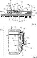
- a radar sensor 10 is shown in different representations.
- the radar sensor 10 can be used, for example, in connection with a driver assistance system of a motor vehicle.
- the radar sensor 10 comprises an openable radar sensor housing 12 in which a ceramic substrate 90 with a radar antenna 14 and a circuit board 16 with components 18 for signal processing and voltage supply are arranged. Furthermore, the radar sensor 10 has a connection plug 20 which leads out of the radar sensor housing 12 and via which the corresponding signal lines and power supply lines can be connected.
- the radar sensor housing 12 is composed of a basic housing part 22 and a radome 24.
- the basic housing part 22 is made of aluminum, for example.
- the radome 24 is made of plastic, for example PBT.
- the radar sensor housing 12 has approximately the shape of a cuboid.
- the basic housing part 22 and the radome 24 each have the shape of an approximately cuboid trough.
- the radome 24 is placed on an edge of a peripheral wall of the basic housing part 22.
- a circumferential wall 28 of the radome 24 engages around the circumferential wall of the base housing part 22.
- the basic housing part 22 has an installation side 26 with an installation opening.
- the ceramic substrate 90 with the radar antenna 14 and the circuit board 16 can be installed through the installation opening.
- the installation side 26 is openably closed with the radome 24.
- the basic housing part 22, the ceramic substrate 90 with the radar antenna 14, the circuit board 16 and the radome 24 are put together parallel to an imaginary assembly axis 30.
- the radome 24 is fixed to the base housing part 22 by means of a total of four essentially identical clamp connections 32.
- the radome 24 is pressed with the clamp connections 32 parallel to the assembly axis 30 against the edge of the peripheral wall of the base housing part 22.
- the clamp connections 32 are located on opposite longitudinal sides of the radar sensor housing 12. Two of the clamp connections 32 are arranged on the same longitudinal side of the radar sensor housing 12.
- Each clamp connection 32 comprises an elastic clamp element 34 on the side of the radome 24 and a latching lug 36 on the side of the base housing part 22.
- the latching lugs 36 are located on the outer circumferential side of the base housing part 22 and rise radially outward with respect to the assembly axis 30. Each of the latching lugs 36 has a wedge-like bevel 38 on its side facing the installation side 26. On the side facing away from the installation side 26, each latching lug 36 has a latching groove 40.
- the clip elements 34 are each elastic spring elements, for example made of spring steel.
- the clamp elements 34 are described below using the clamp element 34 from FIG Figure 4 explained in more detail.
- the clamp element 34 In the area of one of its ends 42, the clamp element 34 has a bend of approximately 90 °. The portion of the clamp element 34 in the region of this bend is embedded in the peripheral wall 28 of the radome 24. The clamp element 34 extends in the region of its end 42 in front of the 90 ° bend with respect to the assembly axis 30 radially inward into a cover-side shoulder 48 of the radome 24. On the end 42 The side facing away from the 90 ° bend, the clamp element 34 extends roughly approximately parallel to the assembly axis 30.
- the clamp element 34 has an S-shaped bend 44 in its central part running approximately parallel to the assembly axis 30.
- the S-shaped bend 44 is located in an area outside the material of the peripheral wall 28.
- the S-shaped bend 44 is in the assembled state approximately at the level of the wedge-like bevel 38 of the corresponding latching lug 36.
- a bending section of the S-shaped bend 44, which faces the peripheral wall 28 of the radome 24, rises towards the peripheral wall of the base housing part 22.
- the clamp element 34 has a latching eye 46 between the S-shaped bend 44 and a free end of the clamp element 34.
- the locking eyelet 46 has the shape of a rectangular window.
- the inner dimensions of the locking lug 46 are somewhat larger than the corresponding outer dimensions of the locking lug 36.
- the locking lug 46 can thus be guided over the locking lug 36 from the outside. In the Figure 4 are indicated by dashed lines for the sake of clarity because of the side boundaries of the locking lug 46 that are actually covered by the locking lug 36.
- the cover-side shoulder 48 forms a rear delimitation of a sealing groove 50, viewed axially to the assembly axis 30 from the radome 24.
- the sealing groove 50 is delimited at the front by a projection 52 of the base housing part 22.
- the projection 52 extends circumferentially on the outer circumferential side of the base housing part 22 with respect to the assembly axis 30.
- the projection 52 is located between the installation side 26 and the latching lug 36, viewed axially to the assembly axis 30.
- the sealing groove 50 is delimited on its radially inner side with respect to the assembly axis 30 by the peripheral wall of the base housing part 22. On the radially outer side, the sealing groove 50 is delimited by the peripheral wall 28 of the radome 24.
- the circumferential wall 28 overlaps the projection 22.
- the circumferential wall 28 lies with its radially inner circumferential side with respect to the assembly axis 30 on the radially outer circumferential side of the projection 22.
- a seal 54 which is circumferentially connected with respect to the assembly axis 30, is arranged sealingly in the radial direction.
- the radome 24 also has a total of four housing-side clamping elements 56 of a clamping device 58 for clamping the ceramic substrate 90 with the radar antenna 14.
- the housing-side clamping elements 56 are in the Figure 2 , in which the radome 24 is shown transparently for the sake of clarity, and the Figure 3 shown.
- the housing-side clamping elements 56 are arranged on the inner top side of the radome 24 facing the base housing part 22.
- the housing-side clamping elements 56 are each approximately cuboid pedestals which, viewed in the direction of the assembly axis 30, extend away from the top side of the radome 24.
- housing-side clamping elements 56 are located in the area of the same circumferential side of the circumferential wall 28, on which the respective clamp elements 34 are also arranged.
- the housing-side clamping elements 56 viewed in the projection, are located approximately between the respective adjacent clamp elements 34.
- the connector 20 leads through a peripheral side of the radar sensor housing 12 between the clamp connections 32 there to the outside. In the interior of the radar sensor housing 12, the connector 20 is electrically and mechanically connected to the circuit board 16. In the usual spatial operational orientation of the radar sensor 10, which in the Figure 2 is shown, the connector 20 is spatially below. In this way it is better protected against the ingress of moisture and water.
- the circuit board 16 is a so-called FR4 circuit card.
- the circuit board 16 is designed as a rectangular flat plate. She's not in here Of further interest, they are fastened in the base housing 22 in such a way that their opposing surfaces each extend perpendicular to the mounting axis 30.
- the components 18 for signal processing and voltage supply are mounted on the surface of the circuit board 16 facing away from the installation side 26 and are electrically connected to corresponding conductor tracks.
- connection device 62 On the surface of the printed circuit board 16 facing the installation side 26, two elongate connection strips 60 of a connection device 62 according to a first exemplary embodiment are arranged.
- the connection device 62 is used for the mechanical and electrical connection of the ceramic substrate 90 to the radar antenna 14.
- the connection strips 60 run as in FIG Figure 2 shown, parallel to one another and each extend between those circumferential sides of the radar sensor housing 12 on which the respective clamp connections 32 are arranged.
- a section of the circuit board 16 with one of the terminal strips 60 is shown in FIG Figure 3 shown in section.
- the connection strips 60 are mechanically connected to the circuit board 16 and electrically to corresponding conductor tracks of the circuit board 16.
- absorber element 64 is flatly attached to the corresponding surface of the printed circuit board 16, for example glued on.
- the absorber element 64 serves to dampen electromagnetic radiation.
- connection strips 60 The structure of the two connection strips 60 is essentially identical. In the following, the structure is based on the terminal strip 60 from FIG Figure 3 explained in more detail.
- the terminal strip 60 has an electrical contact device 66 for making electrical contact with corresponding electrical contact areas 68 on the side of the ceramic substrate 90 with the radar antenna 14. Furthermore, the terminal strip 60 comprises a connection-side clamping element 70 of the clamping device 58. In addition, the terminal strip 60 has an elongated connection base body 72, on which the connection-side clamping element 70 is realized in one piece and in which a plurality of electrical contact elements 74 of the contact device 66 are mounted.
- connection base body 72 is made of electrically insulating material. It extends between the circumferential sides of the radar sensor housing 12.
- the connection-side clamping element 70 is located on a longitudinal side that faces the other connection strip 60 of the connection device 62.
- the connection-side clamping element 70 rises like a pedestal away from the circuit board 16 and over the entire length of the Connection body 72.
- a recess 76 is arranged on the side of the connection-side clamping element 70 facing away from the other connection body 72.
- the recess 76 is open on its side facing away from the circuit board 16. It extends almost over the entire length of the connection base body 72.
- a guide gap 78 is located for the electrical contact elements 78.
- the guide gap 78 extends on the one hand almost over the entire length of the connection base body 72.
- the guide gap 78 connects a rear side of the connection base body 72 facing away from the other connection strip 60 with the recess 76.
- the guide gap 78 opens on the circuit board 16 facing side.
- a pair of holding rods 80 for positioning and mounting the electrical contact elements 74 is arranged in each case.
- the holding rods 80 extend parallel to one another along the connection base body 72.
- the holding rods 80 are made of electrically insulating material.
- a tool holder 82 leads through the upper side of the platform of the connection base body 62 facing away from the printed circuit board 16.
- the tool holder 82 leads into the guide gap 78.
- the tool holder 82 has the shape of an elongated gap which extends beyond the guide gap 78 in the longitudinal direction.
- the tool holder 82 serves to receive and guide an external tool 84 for actuating the contact elements 74.
- the electrical contact device 66 has a multiplicity of electrical contact elements 74 which are arranged next to one another along the connection base body 72 in the guide gap 78.
- the electrical contact elements 74 are not in electrical contact with one another.
- the contact elements 74 of the exemplary embodiment shown are constructed essentially identically.
- Each contact element 74 consists of an elongated elastic electrical conductor, for example a metal spring.
- the contact elements 74 are based on the in Figure 3 contact element 74 shown in more detail.
- the contact element 74 extends through the two openings of the guide gap 78.
- the contact element 74 is mounted between the corresponding holding rods 80 of the two holding rod pairs.
- the contact element 74 is electrically and mechanically connected to a corresponding electrically conductive area of the circuit board 16, for example by means of a soldered connection.
- the contact element 74 is equipped with a contact arm 86 outside the guide gap 78. At its end, the contact arm 86 merges into two fork-shaped contact fingers 88.
- the contact fingers 88 encompass an edge of the ceramic substrate 90 on opposite sides viewed in the direction of the assembly axis 30.
- the contact element 74 also has an actuating section 92.
- the actuating section 92 is located between the contact arm 86 and the end of the contact element 74 fastened to the printed circuit board 16.
- the actuating section 92 is arranged within the guide gap 78 in the region of the tool holder 82.
- the tool 84 can act on the actuating section 92 and thus move the contact arm 86 from the contact position I into an assembly position II.
- the assembly position II of the contact arm 86 is in the Figure 3 indicated by dashed lines.
- the contact fingers 88 are bent away from the circuit board 16 in the direction of the installation side 26.
- the fork which is formed by the contact fingers 88, is ready to receive the ceramic substrate 90 in the assembly position II.
- the ceramic substrate 90 has, for example, the shape of a rectangular plate.
- the ceramic substrate 90 is formed from a multilayer ceramic such as LTCC.
- the plate surface of the ceramic substrate 90 facing the installation side 26 of the base housing part 22 forms an emission side 94 for the radar antenna 14.
- the ceramic substrate 90 has corresponding antenna structures not shown in detail in the figures.
- a part of the electrical contact areas 68, which are the ones shown in FIG Figure 3 upper contact fingers 88 of the respective contact elements 74 are assigned.
- a radar TRX chip 96 is arranged on the rear side of the ceramic substrate 90 and electrically contacted accordingly.
- the radar TRX chip 96 has a transmitter and a receiver for corresponding radar signals.
- the radar TRX chip 96 is arranged in the free area between the ceramic substrate 90 and the circuit board 16.
- the radar TRX chip 96 is located between the terminal strips 60.
- the basic housing part 22, the radome 24, the printed circuit board 16 with the connection strips 60 and the connection plug 22 and the ceramic substrate 90 with the radar antenna 14 are each preassembled.
- the circuit board 16 is with its side carrying the components 18 first in an assembly direction 98, which in the Figure 3 is indicated by an arrow, installed parallel to the assembly axis 30 in the basic housing part 22 and fixed there.
- One of the tools 84 is then inserted into the tool receptacles 82 of the two connection strips 60.
- the contact elements 74 are thus moved into their assembly position II against their elastic restoring force.
- the ceramic substrate 90 with the radar antenna 14 is positioned with the rear side facing away from the emission side 94 first in the assembly direction 98 between the connection strips 60 placed in such a way that the respective longitudinal edges come to lie in the forks of the contact fingers 88 of the corresponding contact elements 74.
- the tools 84 are removed from the tool receptacles 82, as a result of which the contact elements 74 move into their respective contact position I due to their elastic restoring force.
- respective electrical contacts are established between the contact fingers 88 and the respective contact areas 68 of the ceramic substrate 90.
- the ceramic substrate 90 rests in the correct installation position on the connection-side clamping elements 70, supported on opposite sides.
- the radome 24 is plugged onto the base housing part 22 in the assembly direction 98 with the seal 54 interposed.
- the corresponding free ends of the clamp elements 34 are each guided over the wedge-like bevels 38 of the latching lugs 36.
- the clamp elements 34 With a locking tool 100, which is in the Figure 4 is indicated, the clamp elements 34 are pressed at their S-shaped bends 44 to the peripheral wall of the base housing part 22, whereby the respective locking eyes 46 slide over the locking lugs 36.
- the clamp elements 34 snap into place in the corresponding snap-in grooves 40 of the snap-in lugs 36 due to the elastic restoring force of the clamp elements 34.
- the radome 24 is pressed in the direction of the assembly axis 30 against the edge of the base housing part 22.
- the housing-side clamping elements 56 press against the emission side 94 of the ceramic substrate 90.
- the housing-side clamping elements 56 are each located opposite the corresponding connection-side clamping element 70. With the housing-side clamping elements 56, a clamping force is generated in the Figure 3 indicated by an arrow 102, with which the ceramic substrate 90 and thus the radar antenna 14 are clamped between the housing-side clamping elements 56 and the respective connection-side clamping elements 70.
- each contact element 74 has only one contact finger 88. Only the rear contact finger 88 in the assembly direction 98, facing away from the printed circuit board 16, can be moved from a contact position I into an assembled position II and vice versa. The correspondingly other contact finger 88 is fixedly arranged on the side facing the printed circuit board 16
Description
Die Erfindung betrifft einen Radarsensor für ein Fahrzeug, aufweisend wenigstens ein Radarsensorgehäuse, in dem wenigstens eine Radarantenne angeordnet ist, wobei das Radarsensorgehäuse wenigstens ein Grundgehäuseteil mit einer Einbauseite wenigstens für die wenigstens eine Radarantenne und ein Radom aufweist, mit dem die Einbauseite verschlossen ist und durch welches beim Betrieb des Radarsensors von der wenigstens einen Radarantenne gesendete Signale und/oder zu empfangene Signale hindurch treten können, wobei das Radarsensorgehäuse eine Mehrzahl von elastischen Klammerelementen aufweist, mit denen das Radom an dem wenigstens einen Grundgehäuseteil befestigt ist.The invention relates to a radar sensor for a vehicle, having at least one radar sensor housing in which at least one radar antenna is arranged, the radar sensor housing having at least one basic housing part with an installation side for at least one radar antenna and a radome with which the installation side is closed and through which signals transmitted by the at least one radar antenna and / or signals to be received can pass through during operation of the radar sensor, the radar sensor housing having a plurality of elastic clamp elements with which the radome is attached to the at least one base housing part.
Ferner betrifft die Erfindung ein Verfahren zum Zusammenbau eines Radarsensors für ein Fahrzeug.The invention also relates to a method for assembling a radar sensor for a vehicle.
Aus der
Der Erfindung liegt die Aufgabe zugrunde, einen Radarsensor und ein Verfahren der eingangs genannten Art gestalten, bei denen der Radarsensor einfacher zusammengebaut, insbesondere das Radom einfacher mechanisch an dem Grundgehäuseteil befestigt werden kann.The invention is based on the object of designing a radar sensor and a method of the type mentioned at the outset, in which the radar sensor can be assembled more easily, in particular the radome can be mechanically fastened to the basic housing part more easily.
Diese Aufgabe wird erfindungsgemäß durch die Merkmale von Anspruch 1 gelöst.According to the invention, this object is achieved by the features of claim 1.
Ein Radom ist bekanntermaßen eine geschlossene Schutzhülle, die Radarantennen vor äußeren mechanischen und chemischen Einflüssen wie Wind oder Regen schützt. Bei Radoms werden bekanntermaßen Materialien verwendet, die für Radarsignale besonders gut durchlässig sind.As is well known, a radome is a closed protective cover that protects radar antennas from external mechanical and chemical influences such as wind or rain. In the case of radomes, it is known that materials are used which are particularly permeable to radar signals.
Erfindungsgemäß ist wenigstens ein Klammerelement an dem Radom vormontiert. Das wenigstens eine Klammerelement kann so verliersicher an dem Radom angeordnet sein. Auf diese Weise kann das wenigstens eine Klammerelement gemeinsam mit dem Radom montiert werden. Mit dem in das Radom integrierte wenigstens eine Klammerelement kann ein Montageaufwand, insbesondere eine Anzahl von erforderlichen Bauteilen an einer Montagelinie, reduziert werden. Durch die Verwendung von Klammerelementen kann der Radarsensor ohne zusätzliche Schweiß-, Löt-, Klebe- und/oder Schraubprozesse aufgebaut werden. Auf diese Weise können das Radom und das wenigstens eine Grundgehäuseteil, welche auch aus unterschiedlichen Materialien bestehen können, stabil miteinander verbunden werden. Mithilfe der elastischen Klammerelemente kann eine mechanische Grundspannung realisiert werden, mit welcher die wenigstens eine Radarantenne festgeklemmt und fixiert werden kann. Vorteilhafterweise kann wenigstens eines der Klammerelemente als Federelement realisiert sein. Federelemente können elastisch ausgestaltet sein.According to the invention, at least one clamp element is preassembled on the radome. The at least one clamp element can thus be arranged on the radome in a captive manner. In this way, the at least one clamp element can be mounted together with the radome. With the at least one clamp element integrated into the radome, assembly work, in particular a number of components required on an assembly line, can be reduced. By using clamp elements, the radar sensor can be set up without additional welding, soldering, gluing and / or screwing processes. In this way, the radome and the at least one basic housing part, which can also consist of different materials, can be connected to one another in a stable manner. With the help of the elastic clamp elements, a mechanical basic tension can be realized with which the at least one radar antenna can be clamped and fixed. Advantageously, at least one of the clip elements can be implemented as a spring element. Spring elements can be designed to be elastic.
Erfindungsgemäß weist wenigstens ein Klammerelement Federstahl auf oder besteht daraus. Federstahl kann einfach verarbeitet werden und ist elastisch biegbar. Vorteilhafterweise kann das wenigstens eine Grundgehäuseteil Metall, insbesondere Aluminium, aufweisen oder daraus bestehen. Auf diese Weise kann ein mechanisch stabiles Radarsensorgehäuse realisiert werden.According to the invention, at least one clamp element comprises or consists of spring steel. Spring steel can be processed easily and is flexible and flexible. The at least one basic housing part can advantageously comprise or consist of metal, in particular aluminum. In this way, a mechanically stable radar sensor housing can be realized.
Vorteilhafterweise kann das Radom insbesondere thermoplastischen Kunststoff, insbesondere Polybutylenterephthalat (PBT) und/oder Polyamid (PA), aufweisen oder daraus bestehen. Auf diese Weise kann das Radom für die Radarsignale durchlässig sein. Es ist insbesondere nicht erforderlich, dass sowohl das wenigstens eine Grundgehäuseteil und das Radom aus Kunststoff bestehen. Bekanntermaßen können Gehäuseteile aus Kunststoff mit der Zeit auf sie einwirkenden Drücken nachgeben. Durch die Elastizität der Klammerelemente kann dies kompensiert werden. So kann auch bei einer Verbindung von Gehäuseteilen, insbesondere einem Radom und/oder einem Grundgehäuseteil, aus Kunststoff über die Lebensdauer ein konstanter Druck aufrechterhalten werden. Mit der erfindungsgemäßen Klammerverbindung kann verhindert werden, dass sich die Verbindung zwischen dem wenigstens einen Grundgehäuseteil und dem Radom mit der Zeit lockert.Advantageously, the radome can in particular comprise or consist of thermoplastic plastic, in particular polybutylene terephthalate (PBT) and / or polyamide (PA). In this way, the radome can be transparent to the radar signals. It In particular, it is not necessary for both the at least one basic housing part and the radome to be made of plastic. It is known that housing parts made of plastic can give way to pressures acting on them over time. This can be compensated for by the elasticity of the clamp elements. Thus, even with a connection of housing parts, in particular a radome and / or a base housing part, made of plastic, a constant pressure can be maintained over the service life. The clamp connection according to the invention can prevent the connection between the at least one basic housing part and the radome from loosening over time.
Die Erfindung kann bei einem Fahrzeug, insbesondere einem Kraftfahrzeug, verwendet werden. Vorteilhafterweise kann die Erfindung bei einem Landfahrzeug, insbesondere einem Personenkraftwagen, Lastkraftwagen, einem Bus, einem Motorrad oder dergleichen, verwendet werden. Die Erfindung kann auch bei autonomen oder wenigstens teilweise autonomen Fahrzeugen eingesetzt werden.The invention can be used in a vehicle, in particular a motor vehicle. The invention can advantageously be used in a land vehicle, in particular a passenger car, truck, bus, motorcycle or the like. The invention can also be used in autonomous or at least partially autonomous vehicles.
Der Radarsensor kann vorteilhafterweise mit wenigstens einer elektronischen Steuervorrichtung des Fahrzeugs, insbesondere einem Fahrerassistenzsystem und/oder einer Fahrwerksregelung und/oder einer Fahrer-Informationseinrichtung, verbunden oder Teil einer solchen sein. Auf diese Weise können die mit dem Radarsensor erfassten Objektdaten, insbesondere die Entfernung, Orientierung und/oder Relativgeschwindigkeit eines Objekts relativ zum Fahrzeug, an die Steuervorrichtung übermittelt und zur Beeinflussung von Fahrfunktionen, insbesondere der Geschwindigkeit, einer Bremsfunktion, einer Lenkungsfunktion und/oder einer Ausgabe eines Hinweis-und/oder Warnsignals insbesondere für den Fahrer, verwendet werden.The radar sensor can advantageously be connected to or part of at least one electronic control device of the vehicle, in particular a driver assistance system and / or a chassis control and / or a driver information device. In this way, the object data recorded with the radar sensor, in particular the distance, orientation and / or relative speed of an object relative to the vehicle, can be transmitted to the control device and used to influence driving functions, in particular the speed, a braking function, a steering function and / or an output an information and / or warning signal, in particular for the driver.
Vorteilhafterweise kann der Radarsensor, insbesondere die Radarantenne, zur Verwendung in einem Radarband zwischen 76 GHz und 81 GHz ausgestaltet sein. Vorteilhafterweise kann der Radarsensor, insbesondere eine Antenne auf Keramiksubstrat, zur Verwendung in einem sogenannten Automotive Radarband ausgestaltet sein. Auf diese Weise kann der Radarsensor im Automobilbereich eingesetzt werden.The radar sensor, in particular the radar antenna, can advantageously be designed for use in a radar band between 76 GHz and 81 GHz. The radar sensor, in particular an antenna on a ceramic substrate, can advantageously be designed for use in what is known as an automotive radar band. In this way, the radar sensor can be used in the automotive sector.
Erfindungsgemäß ist eines der Klammerelemente im Bereich eines seiner Enden mit dem Radom verbunden, und in das Material des Radoms eingebettet. Auf diese Weise kann das wenigstens eine Klammerelement mit einem dem verbundenen Ende abgewandten Abschnitt mit dem wenigstens einen Grundgehäuseteil insbesondere lösbar verbunden sein oder werden.According to the invention, one of the clamp elements is connected to the radome in the region of one of its ends and into the material embedded in the radome. In this way, the at least one clamp element can, in particular, be releasably connected to the at least one base housing part with a section facing away from the connected end.
Vorteilhafterweise kann wenigstens ein Ende des wenigstens einen Klammerelements in das Material des Radoms eingegossen sein. Auf diese Weise kann einem stabile Verbindung hergestellt werden. Das wenigstens eine Klammerelement kann bereits bei der Herstellung des Radoms nach einem Kunststoffformverfahren, insbesondere einem Spritz- und/oder Gussverfahren, in das Material des Radoms eingebettet werden.Advantageously, at least one end of the at least one clip element can be cast into the material of the radome. In this way a stable connection can be established. The at least one clamp element can already be embedded in the material of the radome during the manufacture of the radome using a plastic molding process, in particular an injection and / or casting process.
Erfindungsgemäß weist wenigstens ein Klammerelement wenigstens eine S-förmige Biegung auf. Auf diese Weise kann das wenigstens seine Klammerelement insbesondere zum Schließen und/oder Öffnen der Klammerverbindung entsprechend elastisch gebogen werden. Im Bereich der S-förmigen Biegung kann das wenigstens eine Klammerelement dabei elastisch gestreckt werden. Nach dem Erreichen der Schließposition beziehungsweise der Öffnungsposition kann das wenigstens eine Klammerelement aufgrund seiner Rückstellkraft seine ursprüngliche Form selbsttätig wieder einnehmen. Nach dem Schließen der Klammerverbindung kann so aufgrund der Federwirkung eine entsprechende Klemmkraft erzeugt werden, mit der das Radom gegen das wenigstens eine Grundgehäuseteil und/oder gegebenenfalls gegen die wenigstens eine Radarantenne gepresst werden kann.According to the invention, at least one clamp element has at least one S-shaped bend. In this way, the at least its clip element can be correspondingly elastically bent, in particular for closing and / or opening the clip connection. In the area of the S-shaped bend, the at least one clamp element can be stretched elastically. After reaching the closed position or the open position, the at least one clamp element can automatically resume its original shape due to its restoring force. After the clamp connection has been closed, a corresponding clamping force can thus be generated due to the spring action, with which the radome can be pressed against the at least one basic housing part and / or optionally against the at least one radar antenna.
Bei einer weiteren vorteilhaften Ausführungsform kann wenigstens eines der Klammerelemente wenigstens einen Rastabschnitt aufweisen. Der wenigstens eine Rastabschnitt kann mit einem entsprechenden gehäuseseitigen Rastabschnitt auf Seiten des Grundgehäuseteils verrasten. Auf diese Weise kann die Klammerverbindung mittels einer Rastverbindung gesichert werden. Ferner kann eine derartige Rastverbindung lösbar ausgestaltet sein. So kann bei Bedarf, insbesondere zu Wartungszwecken, das Radarsensorgehäuse wieder geöffnet werden.In a further advantageous embodiment, at least one of the clip elements can have at least one latching section. The at least one latching section can latch with a corresponding latching section on the housing side on the side of the basic housing part. In this way, the clamp connection can be secured by means of a latching connection. Furthermore, such a latching connection can be designed to be detachable. In this way, the radar sensor housing can be opened again if necessary, in particular for maintenance purposes.
Vorteilhafterweise kann wenigstens eines der Klammerelemente eine Rastöse aufweisen. Entsprechend kann auf Seiten des Grundgehäuseteils eine entsprechende Rastnase angeordnet sein. Die gehäuseseitige Rastnase kann zum Verschließen und Sichern der Klammerverbindung in die Rastöse des wenigstens einen Klammerelements einrasten.At least one of the clip elements can advantageously have a locking eyelet. Correspondingly, a corresponding latching lug can be arranged on the side of the basic housing part. The latch on the housing side can be used to close and Lock the clamp connection in the locking eyelet of the at least one clamp element.
Bei einer weiteren vorteilhaften Ausführungsform kann wenigstens eines der Klammerelemente von außerhalb des Radarsensorgehäuses zugänglich angeordnet sein. Auf diese Weise kann das wenigstens eine Klammerelement von außen betätigt werden.In a further advantageous embodiment, at least one of the clip elements can be arranged to be accessible from outside the radar sensor housing. In this way, the at least one clamp element can be actuated from the outside.
Bei einer weiteren vorteilhaften Ausführungsform kann das wenigstens eine Klammerelement wenigstens einen Betätigungsabschnitt aufweisen. In dem wenigstens einen Betätigungsabschnitt kann das wenigstens eine Klammerelement zum öffnen und/oder schließen betätigt und dabei entsprechend elastisch gebogen werden.In a further advantageous embodiment, the at least one clamp element can have at least one actuation section. In the at least one actuating section, the at least one clamp element can be actuated to open and / or close and, in doing so, be bent elastically accordingly.
Erfindungsgemäß weist das wenigstens eine Klammerelement wenigstens eine S-förmige Biegung auf. Auf diese Weise kann die Biegecharakteristik des wenigstens einen Klammerelements verbessert werden.According to the invention, the at least one clamp element has at least one S-shaped bend. In this way, the bending characteristics of the at least one clamp element can be improved.
Vorteilhafterweise kann der wenigstens eine Betätigungsabschnitt an einer S-förmigen Biegung des wenigstens einen Klammerelements angeordnet sein. Durch entsprechende Druckausübung auf die S-förmigen Biegung kann diese gestreckt und damit das wenigstens eine Klammerelement verlängert werden. So kann ein Abstand zwischen dem in dem Radom befestigten Ende und einem Befestigungsabschnitt für das Grundgehäuseteil, insbesondere einem Rastabschnitt, vergrößert werden. Der Befestigungsabschnitt kann auf diese Weise mit einen entsprechenden Befestigungsabschnitt auf Seiten des wenigstens einen Grundgehäuseteils in Verbindung gebracht werden. Insbesondere kann ein etwaiger Rastabschnitt so über einen entsprechenden gehäuseseitigen Rastabschnitt geschoben oder gestülpt werden und anschließend durch die elastische Rückstellkraft des wenigstens einen Klammerelements mit diesem eine sichere Rastverbindung eingehen.The at least one actuating section can advantageously be arranged on an S-shaped bend of the at least one clamp element. By exerting appropriate pressure on the S-shaped bend, it can be stretched and the at least one clamp element can thus be lengthened. In this way, a distance between the end fastened in the radome and a fastening section for the basic housing part, in particular a latching section, can be increased. In this way, the fastening section can be brought into connection with a corresponding fastening section on the side of the at least one base housing part. In particular, a possible latching section can thus be pushed or slipped over a corresponding latching section on the housing side and then enter into a secure latching connection with the at least one clamp element due to the elastic restoring force of the latter.
Vorteilhafterweise kann der wenigstens eine Betätigungsabschnitt zum Angriff wenigstens eines Werkzeuges ausgestaltet sein. Auf diese Weise kann eine Krafteinwirkung auf den wenigstens ein Betätigungsabschnitt verbessert werden.The at least one actuation section can advantageously be designed to engage at least one tool. In this way, the action of force on the at least one actuation section can be improved.
Bei einer weiteren vorteilhaften Ausführungsform können mehrere Klammerelemente bezüglich einer Zusammenbaurichtung des Radoms mit dem wenigstens einen Grundgehäuseteil umfangsmäßig verteilt angeordnet sein. Auf diese Weise kann das Radom umfangsmäßig gleichmäßiger mit dem wenigstens einen Grundgehäuseteil verbunden und gegen dieses gedrückt werden.In a further advantageous embodiment, a plurality of clamp elements can be distributed circumferentially with respect to a direction of assembly of the radome with the at least one basic housing part. In this way, the radome can be connected more uniformly circumferentially to the at least one basic housing part and pressed against it.
Bei einer weiteren vorteilhaften Ausführungsform kann das Radom wenigstens ein Klemmelement zum Fixieren wenigstens einer Radarantenne aufweisen.In a further advantageous embodiment, the radome can have at least one clamping element for fixing at least one radar antenna.
Vorteilhafterweise kann das wenigstens eine Klemmelement des Radoms Teil einer Anschlussvorrichtung für wenigstens eine Radarantenne sein. Auf diese Weise kann die wenigstens eine Radarantenne mithilfe des Radoms in dem Radarsensorgehäuse fixiert werden. Die wenigstens eine Radarantenne kann bei der Montage des Radoms auf einem Grundgehäuseteil des Radarsensors automatisch mit dem entsprechenden wenigstens einen Klemmelement festgeklemmt werden. So kann in einem Arbeitsgang das Radarsensorgehäuse mit dem Radom verbunden und dabei gleichzeitig die wenigstens eine Radarantenne im Radarsensorgehäuse dauerhaft fixiert werden.The at least one clamping element of the radome can advantageously be part of a connection device for at least one radar antenna. In this way, the at least one radar antenna can be fixed in the radar sensor housing with the aid of the radome. The at least one radar antenna can be automatically clamped with the corresponding at least one clamping element when the radome is mounted on a base housing part of the radar sensor. In this way, the radar sensor housing can be connected to the radome in one operation and, at the same time, the at least one radar antenna can be permanently fixed in the radar sensor housing.
Vorteilhafterweise kann die wenigstens eine Radarantenne ein Keramiksubstrat mit wenigstens einer Radarantenne sein. Das Keramiksubstrat mit der Radarantenne kann ein plattenförmiges Keramiksubstrat aufweisen, welches wenigstens ein elektrisches/elektronisches Funktionsbauteil trägt.The at least one radar antenna can advantageously be a ceramic substrate with at least one radar antenna. The ceramic substrate with the radar antenna can have a plate-shaped ceramic substrate which carries at least one electrical / electronic functional component.
Vorteilhafterweise kann der Radarsensor wenigstens eine Anschlussvorrichtung für die wenigstens eine Radarantenne aufweisen.The radar sensor can advantageously have at least one connection device for the at least one radar antenna.
Vorteilhafterweise kann die wenigstens eine Anschlussvorrichtung wenigstens eine Einrichtung zur Fixierung der wenigstens einen Radarantenne insbesondere an einer Leiterplatte aufweisen. Vorteilhafterweise kann die wenigstens eine Einrichtung zur Fixierung wenigstens ein Klemmelement einer Klemmeinrichtung zur Fixierung der wenigstens einen Radarantenne aufweisen.The at least one connection device can advantageously have at least one device for fixing the at least one radar antenna, in particular on a circuit board. The at least one device for fixing can advantageously have at least one clamping element of a clamping device for fixing the at least one radar antenna.
Ferner kann die wenigstens eine Anschlussvorrichtung wenigstens eine elektrische Kontakteinrichtung zum elektrischen Anschluss des wenigstens einen elektrischen/elektronischen Funktionsbauteils insbesondere mit der Leiterplatte aufweisen. Vorteilhafterweise kann die wenigstens eine elektrische Kontakteinrichtung wenigstens ein wenigstens abschnittsweise elastisches elektrisches Kontaktelement aufweisen mit wenigstens einem Kontaktabschnitt zur elektrischen Kontaktierung wenigstens eines elektrischen Kontaktbereichs aufseiten der wenigstens einen Radarantenne.Furthermore, the at least one connection device can have at least one electrical contact device for the electrical connection of the at least one electrical / electronic Have functional component in particular with the circuit board. Advantageously, the at least one electrical contact device can have at least one at least partially elastic electrical contact element with at least one contact section for making electrical contact with at least one electrical contact area on the side of the at least one radar antenna.
Die wenigstens eine Radarantenne kann rein mechanisch gegen wenigstens einen Kontaktabschnitt wenigstens eines elektrischen Kontaktelements der Anschlussvorrichtung gedrückt und mit der wenigstens einen Klemmeinrichtung fixiert werden. Mit der wenigstens einen Klemmeinrichtung kann die wenigstens eine Radarantenne gegen verrutschen insbesondere in einer Ebene fixiert werden und gleichzeitig können die elektrischen Kontakte mit dem wenigstens einen Kontaktabschnitt sichergestellt werden. Der wenigstens eine Kontaktabschnitt kann eine elektrisch leitende Oberfläche aufweisen, welche mit einer elektrisch leitenden Oberfläche des wenigstens einen elektrischen Kontaktbereichs aufseiten der wenigstens einen Radarantenne elektrisch leitend in Kontakt treten kann. Die elektrische Kontaktierung kann alleine durch mechanischen Druck sichergestellt werden. Auf zusätzliche Klebeprozesse und Lötprozesse beim Anschluss der wenigstens einen Radarantenne kann verzichtet werden.The at least one radar antenna can be pressed purely mechanically against at least one contact section of at least one electrical contact element of the connection device and fixed with the at least one clamping device. With the at least one clamping device, the at least one radar antenna can be fixed against slipping, in particular in a plane, and at the same time the electrical contacts with the at least one contact section can be ensured. The at least one contact section can have an electrically conductive surface which can come into electrically conductive contact with an electrically conductive surface of the at least one electrical contact area on the side of the at least one radar antenna. The electrical contact can be ensured solely by mechanical pressure. Additional gluing processes and soldering processes when connecting the at least one radar antenna can be dispensed with.
Vorteilhafterweise kann das wenigstens eine Kontaktelement wenigstens abschnittsweise elastisch sein. Auf diese Weise kann es elastisch verformt, insbesondere gebogen, werden. So können etwaige bauteilbedingte, montagebedingte und/oder betriebsbedingte Toleranzen besser ausgeglichen werden. Ferner kann so das wenigstens eine Kontaktelement insbesondere zu Montagezwecken elastisch verformt werden.The at least one contact element can advantageously be elastic at least in sections. In this way it can be elastically deformed, in particular bent. In this way, any component-related, assembly-related and / or operational-related tolerances can be better compensated for. Furthermore, the at least one contact element can thus be elastically deformed, in particular for assembly purposes.
Vorteilhafterweise können die Oberflächen des wenigstens einen Kontaktelements außerhalb des wenigstens einen Kontaktabschnitts elektrisch leitend oder nicht elektrisch leitend, insbesondere isolierend beschichtet, sein.Advantageously, the surfaces of the at least one contact element outside the at least one contact section can be electrically conductive or non-electrically conductive, in particular coated to be insulating.
Vorteilhafterweise kann das Keramiksubstrat mit der Radarantenne als ebene, insbesondere rechteckige, Platte realisiert sein. Auf diese Weise kann es platzsparend realisiert werden.The ceramic substrate with the radar antenna can advantageously be implemented as a flat, in particular rectangular, plate. In this way, it can be implemented in a space-saving manner.
Vorteilhafterweise kann das Keramiksubstrat eine relative Dielektrizitätskonstante εr von etwa zwischen 7 und 8 aufweisen. Auf derartigen Keramiksubstraten können Strukturen einer Radarantenne wesentlich kleiner ausgeführt werden als auf üblichen Softsubstraten mit typischen relativen Dielektrizitätskonstanten εr von etwa 3.The ceramic substrate can advantageously have a relative dielectric constant ε r of approximately between 7 and 8. Structures of a radar antenna can be made much smaller on such ceramic substrates than on conventional soft substrates with typical relative dielectric constants ε r of about 3.
Vorteilhafterweise kann das Keramiksubstrat aus Mehrlagenkeramik, insbesondere Niedertemperatur-Einbrand-Keramik, ausgestaltet sein. Niedertemperatur-Einbrand-Keramiken sind im englischsprachigen bekannt als Low Temperature Cofired Ceramics (LTCC). Derartige Keramiksubstrat können einfach und kostengünstig hergestellt werden.The ceramic substrate can advantageously be configured from multilayer ceramic, in particular low-temperature single-fused ceramic. Low-temperature fired ceramics are known in English as Low Temperature Cofired Ceramics (LTCC). Such ceramic substrates can be produced simply and inexpensively.
Die Anschlussvorrichtung kann ermöglichen, dass die wenigstens eine Radarantenne, insbesondere das Keramiksubstrat, mit seiner Rückseite, welcher einer Abstrahlseite der Radarantenne abgewandt ist, zu benachbarten Bauteilen beabstandet sein kann und/oder mit entsprechenden Funktionsbauteilen bestückt sein kann. Die Abstrahlseite der wenigstens einen Radarantenne ist die Seite, von der Radarsignale abgestrahlt werden und auf die reflektierte Radar-Echosignale gestrahlt werden.The connection device can enable the at least one radar antenna, in particular the ceramic substrate, to be spaced from adjacent components with its rear side, which faces away from an emission side of the radar antenna, and / or to be equipped with corresponding functional components. The emission side of the at least one radar antenna is the side from which radar signals are emitted and onto which reflected radar echo signals are emitted.
Das wenigstens eine elektrische/elektronische Funktionsbauteil, welches von der wenigstens einen Radarantenne, insbesondere dem Keramiksubstrat, getragen wird, kann vorteilhafterweise wenigstens ein Sende- und/oder Empfangsbauteil und/oder wenigstens eine Antenne oder eine Antennenstruktur oder dergleichen aufweisen oder daraus bestehen. Auf diese Weise kann die wenigstens eine Radarantenne wesentliche Funktionen zum Senden und/oder Empfangen von Radarsignalen tragen.The at least one electrical / electronic functional component carried by the at least one radar antenna, in particular the ceramic substrate, can advantageously have or consist of at least one transmitting and / or receiving component and / or at least one antenna or antenna structure or the like. In this way, the at least one radar antenna can carry out essential functions for transmitting and / or receiving radar signals.
Vorteilhafterweise kann auf der Abstrahlseite der wenigstens einen Radarantenne wenigstens eine Antennenstruktur angeordnet sein. Auf diese Weise kann die Antennenstruktur nahezu frei von Abdeckungen abstrahlen und/oder empfangen.At least one antenna structure can advantageously be arranged on the emission side of the at least one radar antenna. In this way, the antenna structure can radiate and / or receive almost free of covers.
Vorteilhafterweise kann an der Rückseite der wenigstens einen Radarantenne wenigstens ein Empfangs- und/oder Sendebauteil, insbesondere ein Radar-TRX (Transceiver und Receiver)-Chip, angeordnet sein. Auf diese Weise können die Funktionsbauteile, welche nicht direkt zur Abstrahlung oder zum Empfang von Radarsignalen eingesetzt werden, platzsparend auf der Rückseite der wenigstens einen Radarantenne angeordnet werden. Insgesamt können dank der Anschlussvorrichtung beide Oberflächen der wenigstens einen Radarantenne zum Tragen von entsprechenden Funktionsbauteilen verwendet werden.At least one receiving and / or transmitting component, in particular a radar TRX (transceiver and receiver) chip, can advantageously be arranged on the rear side of the at least one radar antenna. In this way, the functional components that are not used directly for emitting or receiving radar signals can be arranged in a space-saving manner on the rear of the at least one radar antenna become. Overall, thanks to the connection device, both surfaces of the at least one radar antenna can be used to carry corresponding functional components.
Vorteilhafterweise kann auf oder hinter der Rückseite der wenigstens einen Radarantenne wenigstens ein Absorberelement angeordnet sein. Mit dem Absorberelement können insbesondere elektromagnetisch Signale, insbesondere Radarsignale und/oder andere Störsignale, gedämpft und/oder abgeschirmt werden.At least one absorber element can advantageously be arranged on or behind the rear side of the at least one radar antenna. With the absorber element, in particular electromagnetic signals, in particular radar signals and / or other interfering signals, can be attenuated and / or shielded.
Vorteilhafterweise kann wenigstens ein Absorberelement zwischen der wenigstens einen Radarantenne und der Leiterplatte angeordnet sein. So kann einerseits die wenigstens eine Radarantenne vor Störsignalen geschützt werden. Andererseits können die Leiterplatte und dortige elektronische Bauteile vor etwa rückwärts abgestrahlten Radarsignalen der wenigstens einen Radarantenne geschützt werden.At least one absorber element can advantageously be arranged between the at least one radar antenna and the circuit board. In this way, on the one hand, the at least one radar antenna can be protected from interfering signals. On the other hand, the circuit board and the electronic components there can be protected from radar signals from the at least one radar antenna that are radiated backwards, for example.
Vorteilhafterweise kann wenigstens ein Absorberelement auf der der wenigstens einen Radarantenne zugewandten Oberfläche der Leiterplatte angeordnet, insbesondere aufgeklebt, sein. Auf diese Weise kann die Rückseite der wenigstens einen Radarantenne freigehalten werden für etwaige Funktionsbauteile.At least one absorber element can advantageously be arranged, in particular glued on, on the surface of the printed circuit board facing the at least one radar antenna. In this way, the back of the at least one radar antenna can be kept free for any functional components.
Vorteilhafterweise können auf der Leiterplatte Bauteile insbesondere zur Signalverarbeitung und/oder Spannungsversorgung angeordnet sein. Auf diese Weise kann der Radarsensor mit einer eigenen Signalverarbeitung und/oder Spannungsversorgung ausgestattet sein.Advantageously, components, in particular for signal processing and / or voltage supply, can be arranged on the printed circuit board. In this way, the radar sensor can be equipped with its own signal processing and / or voltage supply.
Vorteilhafterweise kann wenigstens ein insbesondere elektrisches/elektronisches Bauteil auf einer der wenigstens einen Radarantenne abgewandten Oberfläche der Leiterplatte angeordnet sein. Auf diese Weise kann ein Raum zwischen der wenigstens einen Radarantenne und der Leiterplatte freigehalten werden oder mit anderen Elementen, insbesondere gegebenenfalls einem Absorberelement, versehen werden.Advantageously, at least one in particular electrical / electronic component can be arranged on a surface of the circuit board facing away from the at least one radar antenna. In this way, a space between the at least one radar antenna and the printed circuit board can be kept free or can be provided with other elements, in particular optionally an absorber element.
Vorteilhafterweise kann die Leiterplatte eine sogenannte FR4-Leiterkarte sein. Derartige Leiterkarten können eine im Vergleich insbesondere zu marktbekannten Leiterplatten aus Hartpappe größere mechanische Eigenstabilität aufweisen. FR4 (flame retardant class 4) bezeichnet bekanntermaßen eine Klasse von schwer entflammbaren und flammenhemmenden Verbundstoffen bestehend aus Epoxidharz und Glasfasergewebe.The circuit board can advantageously be a so-called FR4 circuit card. Such circuit cards can have a greater mechanical inherent stability in comparison in particular to circuit boards made of hard cardboard known on the market. FR4 (flame retardant class 4) is known to denote a class of flame-retardant and flame-retardant composite materials consisting of epoxy resin and fiberglass fabric.
Vorteilhafterweise kann wenigstens ein Kontaktabschnitt wenigstens eines Kontaktelements zwischen einer Zusammenbauposition und einer Kontaktposition bewegbar sein. Auf diese Weise kann der wenigstens eine Kontaktabschnitt zum Zusammenbau der wenigstens einen Radarantenne und der Anschlussvorrichtung in eine Zusammenbauposition gebracht werden. In der Zusammenbauposition kann der wenigstens eine Kontaktabschnitt so angeordnet sein, dass er den Zusammenbau nicht behindert. Sobald sich die Radarantenne in der korrekten Montageposition befindet, kann der wenigstens eine Kontaktabschnitt aus seiner Zusammenbauposition in seine Kontaktposition bewegt werden. In der Kontaktposition kontaktiert der wenigstens eine Kontaktabschnitt wenigstens einen entsprechenden Kontaktbereich auf Seiten der wenigstens einen Radarantenne.Advantageously, at least one contact section of at least one contact element can be moved between an assembly position and a contact position. In this way, the at least one contact section can be brought into an assembly position for assembling the at least one radar antenna and the connection device. In the assembly position, the at least one contact section can be arranged in such a way that it does not impede assembly. As soon as the radar antenna is in the correct assembly position, the at least one contact section can be moved from its assembly position into its contact position. In the contact position, the at least one contact section makes contact with at least one corresponding contact area on the side of the at least one radar antenna.
Vorteilhafterweise kann das wenigstens eine Kontaktelement in seiner Zusammenbauposition und/oder seiner Kontaktposition eine elastische mechanische Vorspannung aufweisen. Auf diese Weise kann eine entsprechende Rückstellkraft realisiert werden zum Rückstellen des wenigstens einen Kontaktelements in die jeweils andere Position. Je nach Richtung der Rückstellkraft kann eine Montage und/oder Demontage des Radarsensors, insbesondere ein Einbau und/oder Ausbau der wenigstens einen Radarantenne, vereinfacht werden. Mit einer mechanischen Vorspannung in der Kontaktposition des wenigstens einen Kontaktelements kann eine elektrische Kontaktierung verbessert werden.The at least one contact element can advantageously have elastic mechanical prestress in its assembly position and / or in its contact position. In this way, a corresponding restoring force can be implemented for restoring the at least one contact element into the respective other position. Depending on the direction of the restoring force, assembly and / or disassembly of the radar sensor, in particular installation and / or removal of the at least one radar antenna, can be simplified. With a mechanical preload in the contact position of the at least one contact element, electrical contacting can be improved.
Vorteilhafterweise kann wenigstens ein Kontaktelement wenigstens einen Betätigungsabschnitt aufweisen, mit dem das wenigstens eine Kontaktelement zum Wechsel wenigstens eines Kontaktabschnitts des Kontaktelements aus einer Kontaktposition in eine Zusammenbauposition oder umgekehrt bewegt werden kann. An dem wenigstens einen Betätigungsabschnitt kann das wenigstens eine Kontaktelement entsprechend betätigt werden. Hierzu kann insbesondere ein entsprechendes Werkzeug eingesetzt werden. Zum Einlegen der wenigstens einen Radarantenne kann der wenigstens eine Kontaktabschnitt durch Betätigung an dem wenigstens einen Betätigungsabschnitt zur Einbauseite hin bewegt werden. Sobald die Betätigung des wenigstens einen Kontaktelements beendet wird, insbesondere das Werkzeug entfernt wird, kann der wenigstens eine Kontaktabschnitt insbesondere aufgrund einer mechanischen Rückstellkraft des wenigstens einen Kontaktelements selbsttätig in seine Kontaktposition bewegt werden.Advantageously, at least one contact element can have at least one actuation section with which the at least one contact element can be moved from a contact position to an assembly position or vice versa for changing at least one contact section of the contact element. The at least one contact element can be actuated accordingly on the at least one actuation section. In particular, a corresponding tool can be used for this purpose. To insert the at least one radar antenna, the at least one contact section can be moved towards the installation side by actuating the at least one actuating section. As soon as the actuation of the at least one contact element is ended, in particular the tool is removed, the at least one contact section can be moved automatically into its contact position, in particular due to a mechanical restoring force of the at least one contact element.
Vorteilhafterweise kann das wenigstens eine Kontaktelement in wenigstens einer Lagerstelle gelagert sein. Wenigstens ein Betätigungsabschnitt und wenigstens ein Kontaktabschnitt können sich auf gegenüberliegenden Seiten der wenigstens einen Lagerstelle befinden. Durch Druck auf den wenigstens einen Betätigungsabschnitt kann der wenigstens eine Kontaktabschnitt ähnlich einem Hebel entsprechend bewegt werden.The at least one contact element can advantageously be mounted in at least one bearing point. At least one actuation section and at least one contact section can be located on opposite sides of the at least one bearing point. By pressing on the at least one actuating section, the at least one contact section can be moved accordingly, similar to a lever.
Vorteilhafterweise kann wenigstens eine Lagerstelle zwei gegenüberliegende Lagerelemente, insbesondere Haltestäbe, aufweisen. Zwischen den Lagerelementen kann das wenigstens eine Kontaktelement beidseitig insbesondere verschiebbar gelagert werden.Advantageously, at least one bearing point can have two bearing elements lying opposite, in particular holding rods. The at least one contact element can be mounted in particular displaceably on both sides between the bearing elements.
Vorteilhafterweise kann wenigstens ein Kontaktelement zwischen zwei Lagerstellen gelagert sein. Wenigstens ein Betätigungsabschnitt kann sich zwischen den beiden Lagerstellen befinden. Wenigstens ein Kontaktabschnitt kann sich in einem Bereich außerhalb der beiden Lagerstellen befinden.Advantageously, at least one contact element can be mounted between two bearing points. At least one actuation section can be located between the two bearing points. At least one contact section can be located in an area outside the two bearing points.
Vorteilhafterweise kann ein dem wenigstens einen Kontaktabschnitt abgewandtes Ende des wenigstens einen Kontaktelements an der Leiterplatte fixiert und/oder elektrisch kontaktiert sein. Auf diese Weise kann durch entsprechende Wahl der Lagerstellen und entsprechende Anordnung des wenigstens einen Betätigungsabschnitts relativ zu den Lagerstellen der wenigstens eine Kontaktabschnitt um das fixierte Ende des wenigstens einen Kontaktelements zum Wechseln zwischen der Zusammenbauposition und der Kontaktposition geschwenkt und/oder gebogen werden.Advantageously, an end of the at least one contact element facing away from the at least one contact section can be fixed to the circuit board and / or electrically contacted. In this way, the at least one contact section can be pivoted and / or bent around the fixed end of the at least one contact element for changing between the assembly position and the contact position by appropriate selection of the bearing points and appropriate arrangement of the at least one actuating section relative to the bearing points.
Vorteilhafterweise kann wenigstens ein Kontaktelement mit wenigstens einem Kontaktabschnitt an wenigstens einer Plattenfläche der wenigstens einen Radarantenne elektrisch kontaktierend angreifen. Als Plattenflächen im Sinne der Erfindung werden die beiden gegenüberliegenden ausgedehnten Oberflächen der Radarantenne, insbesondere des plattenförmigen Keramiksubstrats mit der Radarantenne, bezeichnet. An der wenigstens einen Plattenfläche kann der wenigstens eine Kontaktabschnitt derart angreifen, dass das Strahlungsfeld der Radarantenne bezüglich der Abstrahlrichtung in azimutaler Richtung weniger, vorzugsweise nicht, gestört wird.Advantageously, at least one contact element with at least one contact section can act in an electrically contacting manner on at least one plate surface of the at least one radar antenna. The two opposite, extended surfaces of the radar antenna, in particular of the plate-shaped ceramic substrate with the radar antenna, are referred to as plate surfaces in the sense of the invention. The at least one contact section can act on the at least one plate surface in such a way that that the radiation field of the radar antenna is less, preferably not, disturbed with respect to the emission direction in the azimuthal direction.
Vorteilhafterweise kann wenigstens ein Kontaktabschnitt an einer bezüglich einer Zusammenbaurichtung der wenigstens einen Radarantenne und der wenigstens einen Anschlussvorrichtung vorderen Plattenfläche, insbesondere der Rückseite, der wenigstens einen Radarantenne elektrisch leitend angreifen. Auf diese Weise schränkt die Kontaktierung die entsprechend andere Plattenfläche, insbesondere die Abstrahlseite, nicht ein. Alternativ oder zusätzlich kann wenigstens ein Kontaktabschnitt an einer hinteren Plattenfläche, insbesondere der Abstrahlseite, der wenigstens einen Radarantenne elektrisch leitend angreifen. Alternativ oder zusätzlich kann wenigstens ein Kontaktabschnitt an einer vorderen Plattenfläche der wenigstens einen Radarantenne und wenigstens ein Kontaktabschnitt kann an einer hinteren Plattenfläche angreifen. Auf diese Weise können beide Seiten der wenigstens einen Radarantenne für entsprechende elektrische Kontaktierung genutzt werden.Advantageously, at least one contact section can engage in an electrically conductive manner on a plate surface, in particular the rear side, of the at least one radar antenna which is front with respect to an assembly direction of the at least one radar antenna and the at least one connection device. In this way, the contact does not restrict the correspondingly other plate surface, in particular the emission side. Alternatively or additionally, at least one contact section on a rear plate surface, in particular the emission side, of the at least one radar antenna can engage in an electrically conductive manner. Alternatively or additionally, at least one contact section can act on a front plate surface of the at least one radar antenna and at least one contact section can act on a rear plate surface. In this way, both sides of the at least one radar antenna can be used for corresponding electrical contacting.
Vorteilhafterweise kann wenigstens ein Kontaktelement wenigstens zwei Kontaktfinger aufweisen, welche auf gegenüberliegenden Plattenflächen der wenigstens einen Radarantenne angreifen können und/oder zwei Kontaktelemente können jeweils wenigstens einen Kontaktfinger aufweisen, welche auf gegenüberliegenden Plattenflächen der wenigstens einen Radarantenne angreifen können. Auf diese Weise können die Kontaktfinger die wenigstens eine Radarantenne gabelartig umgreifen.Advantageously, at least one contact element can have at least two contact fingers which can attack opposite plate surfaces of the at least one radar antenna and / or two contact elements can each have at least one contact finger which can attack opposite plate surfaces of the at least one radar antenna. In this way, the contact fingers can grip around the at least one radar antenna like a fork.
Vorteilhafterweise können die Kontaktfinger im Bereich eines Randes der wenigstens einen Radarantenne angreifen. So können die Kontaktfinger den Rand der wenigstens einen Radarantenne umgreifen. Die Kontaktfinger können so eine laterale Positionierung und/oder Fixierung der wenigstens einen Radarantenne weiter verbessern.The contact fingers can advantageously engage in the area of an edge of the at least one radar antenna. In this way, the contact fingers can grip around the edge of the at least one radar antenna. The contact fingers can thus further improve lateral positioning and / or fixation of the at least one radar antenna.
Vorteilhafterweise kann wenigstens ein Kontaktfinger wenigstens einen Kontaktabschnitt aufweisen zum elektrischen Kontaktieren wenigstens eines entsprechenden Kontaktbereichs auf Seiten der wenigstens einen Radarantenne. Vorteilhafterweise können beide Kontaktfinger jeweils einen Kontaktabschnitt aufweisen. So kann auf beiden Plattenflächen des s jeweils eine entsprechende Kontaktierung stattfinden. Alternativ kann lediglich einer der Kontaktfinger eines Kontaktfinger-Paares einen Kontaktabschnitt bilden oder aufweisen. In diesem Fall kann der jeweils andere Kontaktfinger lediglich als Gegenlager dienen.At least one contact finger can advantageously have at least one contact section for electrically contacting at least one corresponding contact area on the side of the at least one radar antenna. Advantageously, both contact fingers can each have a contact section. Corresponding contact can thus take place on each of the two plate surfaces of the device. Alternatively, only one of the contact fingers of a contact finger pair can have a contact section form or have. In this case, the other contact finger can only serve as a counter bearing.
Bei einer Ausführungsform, bei der wenigstens ein Kontaktelement wenigstens zwei Kontaktfinger aufweist, welche auf gegenüberliegenden Plattenflächen angreifen können, können beide Kontaktfinger durch entsprechende Betätigung des wenigstens einen Kontaktelements aus einer Zusammenbauposition in eine Kontaktposition oder umgekehrt bewegt werden.In an embodiment in which at least one contact element has at least two contact fingers which can engage opposite plate surfaces, both contact fingers can be moved from an assembly position into a contact position or vice versa by corresponding actuation of the at least one contact element.
Bei einer Ausführungsform, bei der zwei Kontaktelemente jeweils wenigstens einen Kontaktfinger aufweisen, kann einer der Kontaktfinger durch entsprechende Betätigung des entsprechenden Kontaktelements aus einer Zusammenbauposition in eine Kontaktposition oder umgekehrt bewegt werden. Die beiden Kontaktfinger können so unabhängig voneinander betätigt werden. So kann eine Montage und/oder Demontage des Radarsensors weiter vereinfacht werden.In one embodiment in which two contact elements each have at least one contact finger, one of the contact fingers can be moved from an assembly position into a contact position or vice versa by actuating the corresponding contact element accordingly. The two contact fingers can thus be operated independently of one another. In this way, assembly and / or disassembly of the radar sensor can be further simplified.
Vorteilhafterweise kann wenigstens ein elektrisches Kontaktelement einen Federarm aufweisen, welcher an einem freien Ende wenigstens einen Kontaktfinger mit wenigstens einem Kontaktabschnitt aufweisen kann. Mit einem Federarm können entsprechende Abstände zwischen einem Verbindungsende insbesondere auf Seiten der Leiterplatte und wenigstens einem Kontaktabschnitt insbesondere am freien Ende des Federarms überbrückt werden.Advantageously, at least one electrical contact element can have a spring arm, which can have at least one contact finger with at least one contact section at a free end. With a spring arm, corresponding distances between a connection end, in particular on the printed circuit board side, and at least one contact section, in particular on the free end of the spring arm, can be bridged.
Vorteilhafterweise kann das wenigstens eine elektrische Kontaktelement elektrisch leitendes Material aufweisen. Auf diese Weise kann das wenigstens eine elektrische Kontaktelement als elektrischer Leiter wirken. Zusätzlich oder alternativ kann das wenigstens eine elektrische Kontaktelement elastisches Material aufweisen. Auf diese Weise kann das wenigstens eine Kontaktelement elastisch bewegt, insbesondere geformt, gebogen oder dergleichen, werden.The at least one electrical contact element can advantageously have electrically conductive material. In this way, the at least one electrical contact element can act as an electrical conductor. Additionally or alternatively, the at least one electrical contact element can have elastic material. In this way, the at least one contact element can be moved elastically, in particular shaped, bent or the like.
Vorteilhafterweise kann das wenigstens eine elektrische Kontaktelement aus elektrisch leitendem, elastischem Material sein. So können die elektrisch leitenden Eigenschaften mit den elastischen Eigenschaften kombiniert werden. Vorteilhafterweise kann das wenigstens eine elektrische Kontaktelement aus Metall, insbesondere Federstahl, sein.The at least one electrical contact element can advantageously be made of electrically conductive, elastic material. In this way, the electrically conductive properties can be combined with the elastic properties. The at least one electrical contact element can advantageously be made of metal, in particular spring steel.
Vorteilhafterweise kann wenigstens ein Anschlussgrundkörper der Anschlussvorrichtung wenigstens einen Teil wenigstens eines Kontaktelements und/oder wenigstens ein Klemmelement der wenigstens einen Klemmeinrichtung wenigstens mitbilden und/oder halten. Mit dem wenigstens einen Anschlussgrundkörper kann die Anschlussvorrichtung mechanisch und/oder elektrisch insbesondere mit der Leiterplatte verbunden sein oder werden.Advantageously, at least one connection base body of the connection device can at least co-form and / or hold at least part of at least one contact element and / or at least one clamping element of the at least one clamping device. With the at least one connection base body, the connection device can be or will be connected mechanically and / or electrically, in particular to the printed circuit board.
Vorteilhafterweise kann wenigstens ein Anschlussgrundkörper länglich sein. Auf diese Weise kann er entlang einer Längsseite oder Querseite der wenigstens einen Radarantenne angeordnet werden.Advantageously, at least one connection base body can be elongated. In this way, it can be arranged along a longitudinal side or a transverse side of the at least one radar antenna.
Vorteilhafterweise kann die Anschlussvorrichtung wenigstens eine Anschlussleiste aufweisen oder daraus bestehen. Die Anschlussleiste kann wenigstens einen Anschlussgrundkörper mit wenigstens einem Kontaktelement und wenigstens einem Klemmelement umfassen. An einer länglichen Anschlussleiste können mehrere Kontaktelemente und/oder Klemmelemente nebeneinander angeordnet sein.The connection device can advantageously have or consist of at least one connection strip. The connection strip can comprise at least one connection base body with at least one contact element and at least one clamping element. A plurality of contact elements and / or clamping elements can be arranged next to one another on an elongated connection strip.
Vorteilhafterweise kann wenigstens ein Kontaktelement in und/oder auf und/oder an wenigstens einem Anschlussgrundkörper gelagert sein. Auf diese Weise kann das wenigstens eine Kontaktelement gehalten, positioniert und zwischen seiner Kontaktposition und seiner Zusammenbauposition bewegt werden.Advantageously, at least one contact element can be mounted in and / or on and / or on at least one connection base body. In this way, the at least one contact element can be held, positioned and moved between its contact position and its assembly position.
Vorteilhafterweise kann die Anschlussvorrichtung, gegebenenfalls wenigstens ein Anschlussgrundkörper, wenigstens eine Führung für wenigstens ein Werkzeug zur Betätigung wenigstens eines Betätigungsabschnitts wenigstens eines Kontaktelements aufweisen. Auf diese Weise kann die Anschlussvorrichtung, insbesondere das wenigstens eine Kontaktelement, zur Montage und/oder Demontage einfacher betätigt werden.The connection device, optionally at least one connection base body, can advantageously have at least one guide for at least one tool for actuating at least one actuation section of at least one contact element. In this way, the connection device, in particular the at least one contact element, can be actuated more easily for assembly and / or disassembly.
Vorteilhafterweise kann wenigstens ein Klemmelement einer Zusammenbaurichtung der wenigstens einen Radarantenne und der Anschlussvorrichtung entgegen gerichtet sein und/oder wenigstens ein Klemmelement kann in einer Zusammenbaurichtung der Radarantenne und der Anschlussvorrichtung gerichtet sein. Auf diese Weise kann das wenigstens eine Klemmelement direkt an einer Plattenfläche der wenigstens einen Radarantenne angreifen. So kann eine Klemmkraft besser in die wenigstens eine Radarantenne, insbesondere das Keramiksubstrat, eingeleitet werden.Advantageously, at least one clamping element can be directed opposite to an assembly direction of the at least one radar antenna and the connection device and / or at least one clamping element can be directed in an assembly direction of the radar antenna and the connection device. In this way, the at least one clamping element can be attached directly to a plate surface of the at least one radar antenna attack. A clamping force can thus be better introduced into the at least one radar antenna, in particular the ceramic substrate.
Vorteilhafterweise kann wenigstens ein Klemmelement auf der in Zusammenbaurichtung der Radarantenne mit der Anschlussvorrichtung vorderen Plattenfläche, insbesondere der Rückseite, an der wenigstens einen Radarantenne angreifen und/oder wenigstens ein Klemmelement kann auf der hinteren Plattenfläche, insbesondere der Abstrahlseite, an der wenigstens einen Radarantenne angreifen.Advantageously, at least one clamping element can engage the at least one radar antenna on the front plate surface in the assembly direction of the radar antenna with the connection device, in particular the rear side, and / or at least one clamping element can engage the at least one radar antenna on the rear plate surface, in particular the emission side.
Vorteilhafterweise können zwei Klemmelemente auf in Zusammenbaurichtung gegenüberliegenden Seiten an der wenigstens einen Radarantenne angreifen. Auf diese Weise kann die wenigstens eine Radarantenne zwischen den beiden Klemmelementen eingeklemmt werden.Advantageously, two clamping elements can engage the at least one radar antenna on opposite sides in the assembly direction. In this way, the at least one radar antenna can be clamped between the two clamping elements.
Vorteilhafterweise kann wenigstens ein Klemmelement gegebenenfalls an wenigstens einem Anschlussgrundkörper angeordnet sein. Auf diese Weise kann es gemeinsam mit wenigstens einer Kontakteinrichtung realisiert werden. Alternativ oder zusätzlich kann wenigstens ein Klemmelement an einem Teil des Radarsensorgehäuses angeordnet sein. Auf diese Weise kann das wenigstens eine Klemmelement beim Zusammenbau des Radarsensorgehäuses automatisch gegen die wenigstens eine Radarantenne gepresst werden.Advantageously, at least one clamping element can optionally be arranged on at least one connection base body. In this way, it can be implemented together with at least one contact device. Alternatively or additionally, at least one clamping element can be arranged on part of the radar sensor housing. In this way, the at least one clamping element can be automatically pressed against the at least one radar antenna when the radar sensor housing is being assembled.
Vorteilhafterweise kann wenigstens ein erstes Klemmelement an wenigstens einem Anschlussgrundkörper und wenigstens ein dem ersten Klemmelement zugeordnetes zweites Klemmelement an dem Radarsensorgehäuse angeordnet sein. Auf dem wenigstens einen ersten Klemmelement kann die wenigstens eine Radarantenne beim Zusammenbau abgelegt werden. Anschließend kann beim Schließen des Radarsensorgehäuses die wenigstens eine Radarantenne mit dem wenigstens einen zweiten Klemmelement festgeklemmt werden.Advantageously, at least one first clamping element can be arranged on at least one connection base body and at least one second clamping element assigned to the first clamping element can be arranged on the radar sensor housing. The at least one radar antenna can be placed on the at least one first clamping element during assembly. Subsequently, when the radar sensor housing is closed, the at least one radar antenna can be clamped with the at least one second clamping element.
Vorteilhafterweise kann wenigstens ein Kontaktelement und/oder wenigstens ein Teil der Klemmeinrichtung und/oder gegebenenfalls wenigstens ein Anschlussgrundkörper an der Leiterplatte angeordnet, insbesondere an dieser befestigt und mit dieser elektrisch verbunden, sein.Advantageously, at least one contact element and / or at least part of the clamping device and / or optionally at least one connection base body can be arranged on the printed circuit board, in particular fastened to it and electrically connected to it.
Vorteilhafterweise kann wenigstens ein Kontaktelement und/oder wenigstens ein Teil der Klemmeinrichtung und/oder gegebenenfalls wenigstens ein Anschlussgrundkörper mittels einer Lötverbindung oder einer anderen Bestückungsmethode mit der Leiterplatte verbunden sein.Advantageously, at least one contact element and / or at least part of the clamping device and / or optionally at least one connection base body can be connected to the circuit board by means of a soldered connection or another assembly method.
Vorteilhafterweise kann eine Verbindung des Radoms mit dem Grundgehäuseteil so ausgestaltet sein, dass sie eine mechanische Vorspannung zum Festklemmen der Radarantenne bereitstellt. Auf diese Weise können montagebedingte, betriebsbedingte und/oder bauteilbedingte Toleranzen insbesondere im Bereich des Radarsensorgehäuses besser kompensiert werden.Advantageously, a connection between the radome and the base housing part can be designed in such a way that it provides a mechanical preload for clamping the radar antenna. In this way, assembly-related, operational-related and / or component-related tolerances can be better compensated, especially in the area of the radar sensor housing.
Vorteilhafterweise kann jeweils wenigstens ein Klemmelement und/oder wenigstens ein Kontaktelement, insbesondere ein Anschlussgrundkörper, gegenüberliegend angeordnet sein. Auf diese Weise kann die wenigstens eine Radarantenne an gegenüberliegenden Rändern elektrisch kontaktiert und/oder fixiert werden.Advantageously, at least one clamping element and / or at least one contact element, in particular a connection base body, can be arranged opposite one another. In this way, the at least one radar antenna can be electrically contacted and / or fixed at opposite edges.
Vorteilhafterweise kann gegenüberliegend jeweils wenigstens ein Klemmelement und wenigstens ein Kontaktelement, insbesondere wenigstens ein Anschlussgrundkörper, angeordnet sein.Advantageously, at least one clamping element and at least one contact element, in particular at least one connection base body, can be arranged opposite one another.
Vorteilhafterweise kann wenigstens ein Anschluss für externe Signal- und/oder Stromversorgungsleitungen aus dem Radarsensorgehäuse herausführen. Mit dem wenigstens einen Anschluss können Signal- und/oder Stromversorgungsleitungen des Radarsensors mit entsprechenden externen Leitungen verbunden werden.Advantageously, at least one connection for external signal and / or power supply lines can lead out of the radar sensor housing. With the at least one connection, signal and / or power supply lines of the radar sensor can be connected to corresponding external lines.
Vorteilhafterweise kann der wenigstens eine Anschluss ein elektrischer Anschluss sein. Auf diese Weise können interne elektrische Leitungen und externe elektrische Leitungen miteinander verbunden werden.The at least one connection can advantageously be an electrical connection. In this way, internal electrical lines and external electrical lines can be connected to one another.
Vorteilhafterweise kann der wenigstens eine Anschluss in normaler Einbauorientierung des Radarsensors räumlich unten an dem Radarsensorgehäuse angeordnet sein. Auf diese Weise kann die Gefahr des Eindringen von Feuchtigkeit und Wasser in den Anschluss und/oder das Radarsensorgehäuse verringert werden.The at least one connection can advantageously be arranged spatially at the bottom of the radar sensor housing in the normal installation orientation of the radar sensor. In this way, the risk of moisture and water penetrating into the connection and / or the radar sensor housing can be reduced.
Vorteilhafterweise kann der wenigstens eine Anschluss mit einer Schnellverbindung, insbesondere als Stecker und/oder Buchse, realisiert sein. Auf diese Weise kann der wenigstens eine Anschluss einfach mit entsprechenden externen Leitungsanschlüssen verbunden werden.The at least one connection can advantageously be implemented with a quick connection, in particular as a plug and / or socket. In this way, the at least one connection can easily be connected to corresponding external line connections.
Ferner wird die technische Aufgabe erfindungsgemäß bei dem Verfahren dadurch gelöst, dass wenigstens ein Teil wenigstens einer Anschlussvorrichtung für ein Keramiksubstrat mit einer Radarantenne an einer Leiterplatte angeordnet und mit entsprechenden elektrischen Leitungen elektrisch verbunden wird, die Leiterplatte in einem Grundgehäuseteil eines Radarsensorgehäuses des Radarsensors angeordnet wird, das Keramiksubstrat mit der Radarantenne auf wenigstens einem Klemmelement der wenigstens einen Anschlussvorrichtung auf Seiten der Leiterplatte positioniert wird und mit einer elektrischen Kontakteinrichtung der Anschlussvorrichtung elektrisch kontaktiert wird, ein Radom auf das Grundgehäuseteil montiert und dabei mit wenigstens einem Klemmelement der wenigstens Anschlussvorrichtung auf Seiten des Radoms das Keramiksubstrat mit der Radarantenne gegenüber dem wenigstens einen Klemmelement der wenigstens einen Anschlussvorrichtung auf Seiten der Leiterplatte festgeklemmt wird und das Radom an dem Grundgehäuseteil mittels einer Mehrzahl von elastischen Klammerelementen fixiert wird. Erfindungsgemäß wird die elektrische Kontaktierung zwischen dem Keramiksubstrat mit der Radarantenne und der Leiterplatte beim Positionieren des Keramiksubstrats auf der wenigstens einen Anschlussleitung realisiert. Die Fixierung des Keramiksubstrats wird automatisch beim Anbau des Radoms Mithilfe der elastischen Klammerelemente realisiert.Furthermore, the technical object is achieved according to the invention in the method in that at least part of at least one connection device for a ceramic substrate with a radar antenna is arranged on a circuit board and electrically connected to corresponding electrical lines, the circuit board is arranged in a basic housing part of a radar sensor housing of the radar sensor, the ceramic substrate with the radar antenna is positioned on at least one clamping element of the at least one connection device on the printed circuit board and electrically contacted with an electrical contact device of the connection device, a radome is mounted on the base housing part and with at least one clamping element of the at least connection device on the radome side Ceramic substrate is clamped with the radar antenna opposite the at least one clamping element of the at least one connection device on the circuit board side and the radome is fixed to the base housing part by means of a plurality of elastic clip elements. According to the invention, the electrical contact between the ceramic substrate with the radar antenna and the circuit board is realized when the ceramic substrate is positioned on the at least one connection line. The fixation of the ceramic substrate is realized automatically when the radome is attached with the help of the elastic clamp elements.
Bei einer vorteilhaften Ausgestaltung des Verfahrens kann wenigstens ein Klammerelement zum Schließen einer Rastverbindung mit dem Grundgehäuseteil elastisch gestreckt und so mit einer mechanischen elastischen Vorspannung versehen werden, mit welcher das Radom und das Grundgehäuseteil zusammengepresst werden. Durch die mechanische elastische Vorspannung kann darüber hinaus eine Klemmkraft zwischen den Klemmelementen der wenigstens einen Anschlussvorrichtung erhöht werden. So kann eine Fixierung und eine elektrische Kontaktierung des Keramiksubstrats mit der Radarantenne im Radarsensorgehäuse verbessert werden. Die Fixierung und die elektrische Kontaktierung des Keramiksubstrats mit der Radarantenne erfolgt dabei automatisch beim Verschließen des Radarsensorgehäuses.In an advantageous embodiment of the method, at least one clamp element can be elastically stretched to close a latching connection with the basic housing part and thus provided with a mechanical elastic preload with which the radome and the basic housing part are pressed together. In addition, the mechanical elastic prestress can increase a clamping force between the clamping elements of the at least one connection device. Fixing and electrical contacting of the ceramic substrate with the radar antenna in the radar sensor housing can thus be improved. The fixation and the electrical The ceramic substrate is contacted with the radar antenna automatically when the radar sensor housing is closed.
Vorteilhafterweise kann wenigstens ein elektrisches Kontaktelement der elektrischen Kontakteinrichtung vor dem Positionieren des Keramiksubstrats mit der Radarantenne auf dem wenigstens einen Klemmelement der wenigstens einen Anschlussvorrichtung auf Seiten der Leiterplatte in eine Zusammenbauposition gebracht werden und das wenigstens eine elektrische Kontaktelement kann nach dem Positionieren des Keramiksubstrats mit der Radarantenne in eine Kontaktposition gebracht werden. Auf diese Weise kann das wenigstens eine elektrische Kontaktelement zum Zusammenbau freigegeben und nach dem Einbau des Keramiksubstrats mit der Radarantenne mit dieser elektrisch kontaktiert werden.Advantageously, at least one electrical contact element of the electrical contact device can be brought into an assembly position before the ceramic substrate is positioned with the radar antenna on the at least one clamping element of the at least one connection device on the printed circuit board, and the at least one electrical contact element can be brought into an assembly position after the ceramic substrate has been positioned with the radar antenna be brought into a contact position. In this way, the at least one electrical contact element can be released for assembly and, after the installation of the ceramic substrate with the radar antenna, electrical contact can be made with the latter.
Im Übrigen gelten die im Zusammenhang mit dem erfindungsgemäßen Radarsensor und dem erfindungsgemäßen Verfahren und deren jeweiligen vorteilhaften Ausgestaltungen aufgezeigten Merkmale und Vorteile untereinander entsprechend und umgekehrt. Die einzelnen Merkmale und Vorteile können selbstverständlich untereinander kombiniert werden, wobei sich weitere vorteilhafte Wirkungen einstellen können, die über die Summe der Einzelwirkungen hinausgehen.In addition, the features and advantages shown in connection with the radar sensor according to the invention and the method according to the invention and their respective advantageous configurations apply mutatis mutandis and vice versa. The individual features and advantages can of course be combined with one another, whereby further advantageous effects can arise that go beyond the sum of the individual effects.
Weitere Vorteile, Merkmale und Einzelheiten der Erfindung ergeben sich aus der nachfolgenden Beschreibung, in der Ausführungsbeispiele der Erfindung anhand der Zeichnung näher erläutert werden. Der Fachmann wird die in der Zeichnung, der Beschreibung und den Ansprüchen in Kombination offenbarten Merkmale zweckmäßigerweise auch einzeln betrachten und zu sinnvollen weiteren Kombinationen zusammenfassen. Es zeigen schematisch
- Figur 1
- eine isometrischer Darstellung eines Radarsensors mit einem Radarsensorgehäuse, in dem ein Keramiksubstrat mit einer Radarantenne mit zwei Anschlussleisten gemäß einem ersten Ausführungsbeispiel an eine Leiterplatte des Radarsensors angeschlossen ist;
- Figur 2
- eine Draufsicht auf den Radarsensor der
Figur 1 , wobei ein Radom des Radarsensors transparent gezeigt ist; - Figur 3
- einen Schnitt durch die Leiterplatte und das Keramiksubstrat mit der Radarantenne des Radarsensors aus den
Figuren 1 und 2 im Bereich eine der Anschlussleisten; - Figur 4
- einen Schnitt durch das Radarsensorgehäuse des Radarsensors aus den
Figuren 1 bis 3 im Bereich einer Klemmverbindung zwischen dem Radom und einen Grundgehäuseteil; - Figur 5
- einen Schnitt durch eine Leiterplatte und ein Keramiksubstrat mit einer Radarantenne eines Radarsensors im Bereich einer Anschlussleiste gemäß einem zweiten Ausführungsbeispiel.
- Figure 1
- an isometric view of a radar sensor with a radar sensor housing, in which a ceramic substrate with a radar antenna with two connection strips according to a first embodiment is connected to a circuit board of the radar sensor;
- Figure 2
- a plan view of the radar sensor of
Figure 1 , wherein a radome of the radar sensor is shown transparent; - Figure 3
- a section through the circuit board and the ceramic substrate with the radar antenna of the radar sensor from the
Figures 1 and 2 one of the connection strips in the area; - Figure 4
- a section through the radar sensor housing of the radar sensor from the
Figures 1 to 3 in the area of a clamp connection between the radome and a base housing part; - Figure 5
- a section through a circuit board and a ceramic substrate with a radar antenna of a radar sensor in the area of a terminal strip according to a second embodiment.
In den Figuren sind gleiche Bauteile mit gleichen Bezugszeichen versehen.In the figures, the same components are provided with the same reference symbols.
In den
Der Radarsensor 10 umfasst ein öffenbares Radarsensorgehäuse 12, in dem ein Keramiksubstrat 90 mit einer Radarantenne 14 und eine Leiterplatte 16 mit Bauteilen 18 zur Signalverarbeitung und Spannungsversorgung angeordnet sind. Ferner verfügt der Radarsensor 10 über einen Anschlussstecker 20, welcher aus dem Radarsensorgehäuse 12 herausführt und über den entsprechende Signalleitungen und Stromversorgungsleitungen angeschlossen werden können.The
Das Radarsensorgehäuse 12 ist aus einem Grundgehäuseteil 22 und einem Radom 24 zusammengesetzt. Das Grundgehäuseteil 22 ist beispielsweise aus Aluminium. Das Radom 24 ist aus Kunststoff, beispielsweise PBT.The
Das Radarsensorgehäuse 12 hat insgesamt etwa die Form eines Quaders. Dabei haben das Grundgehäuseteil 22 und das Radom 24 jeweils die Form einer etwa quaderförmigen Wanne. Das Radom 24 ist auf einen Rand einer Umfangswand des Grundgehäuseteils 22 gesteckt. Eine Umfangswand 28 des Radoms 24 umgreift die Umfangswand des Grundgehäuseteils 22.Overall, the
Das Grundgehäuseteil 22 weist eine Einbauseite 26 mit einer Einbauöffnung auf. Durch die Einbauöffnung können bei beim Zusammenbau des Radarsensors 10 das Keramiksubstrat 90 mit der Radarantenne 14 und die Leiterplatte 16 eingebaut werden. Die Einbauseite 26 ist mit dem Radom 24 öffenbar verschlossen. Zum Zusammenbau werden das Grundgehäuseteil 22 das Keramiksubstrat 90 mit der Radarantenne 14, die Leiterplatte 16 und das Radom 24 parallel zu einer gedachten Montageachse 30 zusammengesetzt.The
Das Radom 24 ist mittels insgesamt vier im wesentlichen identische Klammerverbindungen 32 an dem Grundgehäuseteil 22 fixiert. Das Radom 24 wird mit den Klammerverbindungen 32 parallel zur Montageachse 30 gegen den Rand der Umfangswand des Grundgehäuseteils 22 gedrückt. Die Klammerverbindungen 32 befinden sich auf gegenüberliegenden Längsseiten des Radarsensorgehäuses 12. Dabei sind jeweils zwei der Klammerverbindungen 32 auf der gleichen Längsseite des Radarsensorgehäuses 12 angeordnet.The
Jede Klammerverbindung 32 umfasst ein elastisches Klammerelement 34 aufseiten des Radoms 24 und eine Rastnase 36 aufseiten des Grundgehäuseteils 22.Each
Die Rastnasen 36 befinden sich an der äußeren Umfangsseite des Grundgehäuseteils 22 und erheben sich bezüglich der Montageachse 30 nach radial außen. Jede der Rastnasen 36 weist auf ihrer der Einbauseite 26 zugewandten Seite eine keilartige Schräge 38 auf. Auf der der Einbauseite 26 abgewandten Seite verfügt jede Rastnase 36 über eine Rastnut 40.The latching lugs 36 are located on the outer circumferential side of the
Die Klammerelemente 34 sind jeweils elastische Federelemente beispielsweise aus Federstahl. Die Klammerelemente 34 werden im Folgenden anhand des Klammerelements 34 aus der
Im Bereich eines seiner Enden 42 weist das Klammerelement 34 eine Biegung etwa um 90° auf. Der Abschnitt des Klammerelements 34 im Be reich dieser Biegung ist in die Umfangswand 28 des Radoms 24 eingebettet. Das Klammerelement 34 erstreckt sich im Bereich seines Endes 42 vor der 90°-Biegung bezü glich der Montageachse 30 nach radial innen in einen deckelseitigen Absatz 48 des Radoms 24. Auf der dem Ende 42 abgewandten Seite der 90°-Biegung erstreckt sich das Klammerelement 34 grob etwa parallel zur Montageachse 30.In the area of one of its
Das Klammerelement 34 verfügt in seinem etwa parallel zur Montageachse 30 verlaufenden Mittelteil über eine S-förmige Biegung 44. Die S-förmige Biegung 44 befindet sich in einem Bereich außerhalb des Materials der Umfangswand 28. Die S-förmige Biegung 44 befindet sich in montiertem Zustand etwa auf Höhe der keilartigen Schräge 38 der entsprechenden Rastnase 36. Ein Biegeabschnitt der S-förmigen Biegung 44, welcher der Umfangswand 28 des Radoms 24 zugewandt ist, erhebt sich zur Umfangswand des Grundgehäuseteils 22 hin. Ein Biegeabschnitt der S-förmigen Biegung 44, welcher der Umfangswand 28 des Radoms 24 abgewandt ist, erhebt sich von der Umfangswand des Grundgehäuseteils 22 weg nach außen.The
Zwischen der S-förmigen Biegung 44 und einem freien Ende des Klammerelements 34 weist das Klammerelement 34 eine Rastöse 46 auf. Die Rastöse 46 hat die Form eines rechteckigen Fensters. Die Innenabmessungen der Rastöse 46 sind etwas größer als die entsprechenden Außenabmessungen der Rastnase 36. So kann die Rastöse 46 von außen über die Rastnase 36 geführt werden. In der
Der deckelseitige Absatz 48 bildet eine vom Radom 24 axial zur Montageachse 30 betrachtet hintere Begrenzung einer Dichtungsnut 50. Die Dichtungsnut 50 erstreckt sich bezüglich der Montageachse 30 umfangsmäßig entlang der äußeren Umfangsseite des Grundgehäuseteils 22 und umgibt die Einbauseite 26.The cover-
Auf der dem deckelseitigen Absatz 48 bezüglich der Montageachse 30 axial gegenüberliegenden Seite wird die Dichtungsnut 50 vorne von einem Vorsprung 52 des Grundgehäuseteils 22 begrenzt. Der Vorsprung 52 erstreckt sich bezüglich der Montageachse 30 umfangsmäßig an der äußeren Umfangsseite des Grundgehäuseteils 22. Der Vorsprung 52 befindet sich axial zur Montageachse 30 betrachtet zwischen der Einbauseite 26 und der Rastnase 36.On the side axially opposite the cover-
Die Dichtungsnut 50 wird auf ihrer bezüglich der Montageachse 30 radial inneren Seite von der Umfangswand des Grundgehäuseteils 22 begrenzt. Auf der radial äußeren Seite wird die Dichtungsnut 50 von der Umfangswand 28 des Radoms 24 begrenzt. Die Umfangswand 28 überlappt den Vorsprung 22. Die Umfangswand 28 liegt mit ihrer bezüglich der Montageachse 30 radial inneren Umfangsseite an der radial äußeren Umfangsseite des Vorsprung 22 an.The sealing
In der Dichtungsnut 50 ist eine bezüglich der Montageachse 30 umfangsmäßige zusammenhängende Dichtung 54 in radialer Richtung dichtend angeordnet.In the sealing
Das Radom 24 weist ferner insgesamt vier gehäuseseitige Klemmelemente 56 einer Klemmeinrichtung 58 zum festklemmen des Keramiksubstrats 90 mit der Radarantenne 14 auf. Die gehäuseseitigen Klemmelemente 56 sind in der
Der Anschlussstecker 20 führt durch eine Umfangsseite des Radarsensorgehäuses 12 zwischen den dortigen Klammerverbindungen 32 nach außen. Im Inneren des Radarsensorgehäuses 12 ist der Anschlussstecker 20 elektrisch und mechanisch mit der Leiterplatte 16 verbunden. In der üblichen räumlichen Betriebsorientierung des Radarsensors 10, welche in der
Bei der Leiterplatte 16 handelt es sich um eine sogenannte FR4-Leiterkarte. Beispielhaft ist die Leiterplatte 16 als rechteckige ebene Platte ausgestaltet. Sie ist in hier nicht weiter interessierender Weise in dem Grundgehäuse 22 so befestigt, dass sich ihre gegenüberliegenden Oberflächen jeweils senkrecht zur Montageachse 30 erstrecken. Die Bauteile 18 zur Signalverarbeitung und Spannungsversorgung sind auf der der Einbauseite 26 abgewandten Oberfläche der Leiterplatte 16 montiert und mit entsprechenden Leiterbahnen elektrisch verbunden.The
Auf der der Einbauseite 26 zugewandten Oberfläche der Leiterplatte 16 sind zwei längliche Anschlussleisten 60 einer Anschlussvorrichtung 62 gemäß einem ersten Ausführungsbeispiel angeordnet. Die Anschlussvorrichtung 62 dient dem mechanischen und elektrischen Anschluss des Keramiksubstrats 90 mit der Radarantenne 14. Die Anschlussleisten 60 verlaufen, wie in der
Zwischen den beiden Anschlussleisten 60 ist ein in der
Der Aufbau der beiden Anschlussleisten 60 ist im Wesentlichen identisch. Im Folgenden wird der Aufbau anhand der Anschlussleiste 60 aus der
Die Anschlussleiste 60 verfügt über eine elektrische Kontakteinrichtung 66 zur elektrischen Kontaktierung entsprechender elektrischer Kontaktbereiche 68 aufseiten des Keramiksubstrats 90 mit der Radarantenne 14. Ferner umfasst die Anschlussleiste 60 ein anschlussseitiges Klemmelement 70 der Klemmeinrichtung 58. Darüber hinaus weist die Anschlussleiste 60 einen länglichen Anschlussgrundkörper 72 auf, an dem das anschlussseitige Klemmelement 70 einstückig realisiert ist und in welchem eine Mehrzahl von elektrischen Kontaktelementen 74 der Kontakteinrichtung 66 gelagert sind.The
Der Anschlussgrundkörper 72 ist aus elektrisch isolierendem Material. Er erstreckt sich zwischen den Umfangsseiten des Radarsensorgehäuses 12. Auf einer Längsseite, die der anderen Anschlussleiste 60 der Anschlussvorrichtung 62 zugewandt ist, befindet sich das anschlussseitige Klemmelement 70. Das anschlussseitige Klemmelement 70 erhebt sich podestartig von der Leiterplatte 16 weg und über die gesamte Länge des Anschlussgrundkörpers 72.The
Auf der dem anderen Anschlusskörper 72 abgewandten Seite des anschlussseitigen Klemmelements 70 ist eine Vertiefung 76 angeordnet. Die Vertiefung 76 ist auf ihrer der Leiterplatte 16 abgewandten Seite offen. Sie erstreckt sich nahezu über die gesamte Länge des Anschlussgrundkörpers 72.A
Neben der Vertiefung 76 erhebt sich ein Podest, in dem sich ein Führungsspalt 78 für die elektrischen Kontaktelemente 78 befindet. Der Führungsspalt 78 erstreckt sich einerseits nahezu über die gesamte Länge des Anschlussgrundkörpers 72. Andererseits verbindet der Führungsspalt 78 eine der anderen Anschlussleiste 60 abgewandte Rückseite des Anschlussgrundkörpers 72 mit der Vertiefung 76. Auf der Rückseite des Anschlusskörpers 72 öffnet sich der Führungsspalt 78 auf der der Leiterplatte 16 zugewandten Seite.Next to the
Im Bereich einer Öffnung des Führungsspalts 78 zur Vertiefung 76 und der Öffnung zur Rückseite ist jeweils ein Paar von Haltestäben 80 zur Positionierung und Lagerung der elektrischen Kontaktelemente 74 angeordnet. Die Haltestäbe 80 erstrecken sich parallel zueinander entlang des Anschlussgrundkörpers 72. Die Haltestäbe 80 sind aus elektrisch isolierendem Material.In the area of an opening of the
Durch die der Leiterplatte 16 abgewandte Oberseite des Podestes des Anschlussgrundkörpers 62 führt eine Werkzeugaufnahme 82. Die Werkzeugaufnahme 82 führt in den Führungsspalt 78. Die Werkzeugaufnahme 82 hat die Form eines langgestreckten Spaltes, der sich in Längsrichtung des Führungsspalts 78 über diesen hinaus erstreckt. Die Werkzeugaufnahme 82 dient zur Aufnahme und Führung eines externen Werkzeugs 84 zur Betätigung der Kontaktelemente 74.A
Die elektrische Kontakteinrichtung 66 verfügt über eine Vielzahl von elektrischen Kontaktelementen 74, welche nebeneinander entlang des Anschlussgrundkörpers 72 in dem Führungsspalt 78 angeordnet sind. Die elektrischen Kontaktelemente 74 sind untereinander nicht in elektrischen Kontakt. Die Kontaktelemente 74 des gezeigten Ausführungsbeispiels sind im Wesentlichen identisch aufgebaut. Jedes Kontaktelement 74 besteht aus einem länglichen elastischen elektrischen Leiter, beispielsweise eine Metallfeder.The
Im Folgenden werden die Kontaktelemente 74 anhand des in
In einer in der
Das Kontaktelement 74 weist ferner einen Betätigungsabschnitt 92 auf. Der Betätigungsabschnitt 92 befindet sich zwischen dem Kontaktarm 86 und dem an der Leiterplatte 16 befestigten Ende des Kontaktelements 74. Der Betätigungsabschnitt 92 ist innerhalb des Führungsspalts 78 im Bereich der Werkzeugaufnahme 82 angeordnet. An dem Betätigungsabschnitt 92 kann das Werkzeug 84 angreifen und damit den Kontaktarm 86 aus der Kontaktposition I in eine Zusammenbauposition II bewegen. Die Zusammenbauposition II des Kontaktarms 86 ist in der
Das Keramiksubstrat 90 hat beispielhaft die Form einer rechteckigen Platte. Das Keramiksubstrat 90 ist aus Mehrlagenkeramik, beispielsweise LTCC, gebildet. Die der Einbauseite 26 des Grundgehäuseteils 22 zugewandte Plattenfläche des Keramiksubstrats 90 bildet eine Abstrahlseite 94 für die Radarantenne 14. Im Bereich der Abstrahlseite 94 weist das Keramiksubstrat 90 entsprechende, in den Figuren nicht näher bezeichnete Antennenstrukturen auf. Außerdem befinden sich im Bereich der den Anschlussleisten 60 zugewandten Längsrändern an auf der Abstrahlseite 94 ein Teil der elektrischen Kontaktbereiche 68, welche den in der
Auf der der Abstrahlseite 94 abgewandten Rückseite des Keramiksubstrats 90 sind im Bereich der Längsränder des Keramiksubstrats 90 weitere elektrische Kontaktbereiche 68 angeordnet, welche den in der
Zur Herstellung des Radarsensors 10 werden das Grundgehäuseteil 22, das Radom 24, die Leiterplatte 16 mit den Anschlussleisten 60 und dem Anschlussstecker 22 und das Keramiksubstrat 90 mit der Radarantenne 14 jeweils vormontiert.To produce the
Die Leiterplatte 16 wird mit ihrer die Bauteile 18 tragenden Seite voran in einer Zusammenbaurichtung 98, welche in der
Anschließend wird in die Werkzeugaufnahmen 82 der beiden Anschlussleisten 60 jeweils eines der Werkzeuge 84 gesteckt. Damit werden die Kontaktelemente 74 gegen ihre elastische Rückstellkraft in ihre Zusammenbauposition II bewegt.One of the
Das Keramiksubstrat 90 mit der Radarantenne 14 wird mit der der Abstrahlseite 94 abgewandten Rückseite voran in Zusammenbaurichtung 98 zwischen den Anschlussleisten 60 so platziert, dass die jeweiligen Längsränder in den Gabeln der Kontaktfinger 88 der entsprechenden Kontaktelemente 74 zu liegen kommen.The
Die Werkzeuge 84 werden aus den Werkzeugaufnahmen 82 entfernt, wodurch sich die Kontaktelemente 74 aufgrund ihrer elastischen Rückstellkraft in ihre jeweilige Kontaktposition I bewegen. Dabei werden zwischen den Kontaktfingern 88 und den jeweiligen Kontaktbereichen 68 des Keramiksubstrats 90 jeweilige elektrische Kontakte hergestellt. Das Keramiksubstrat 90 liegt in der korrekten Einbauposition auf den anschlussseitigen Klemmelementen 70, auf gegenüberliegenden Seiten gelagert, auf.The
Danach wird das Radom 24 unter Zwischenlage der Dichtung 54 in Zusammenbaurichtung 98 auf das Grundgehäuseteil 22 gesteckt. Dabei werden die entsprechenden freien Enden der Klammerelemente 34 jeweils über die keilartigen Schrägen 38 der Rastnasen 36 geführt. Mit einem Verschlusswerkzeug 100, welches in der
Durch die elastische Vorspannung der Klammerelemente 34 wird das Radom 24 in Richtung der Montageachse 30 gegen den Rand des Grundgehäuseteils 22 gedrückt. Die gehäuseseitigen Klemmelemente 56 drücken dabei gegen die Abstrahlseite 94 des Keramiksubstrats 90. Die gehäuseseitigen Klemmelemente 56 befinden sich jeweils gegenüber des entsprechenden anschlussseitigen Klemmelements 70. Mit den gehäuseseitigen Klemmelementen 56 wird eine Klemmkraft, in der
Zum Ausbau des Keramiksubstrats 90 mit der Radarantenne 14 werden Verrastungen der Klammerverbindung 32 mithilfe des Verschlusswerkzeugs 100 gelöst. Das Radom 24 wird entgegen der Zusammenbaurichtung 98 von dem Grundgehäuseteil 22 entfernt. Die Werkzeuge 84 werden in die jeweiligen Werkzeugaufnahmen 82 gesteckt, sodass die Kontaktelemente 74 in ihre Zusammenbauposition II bewegt werden. Das Keramiksubstrat 90 mit der Radarantenne 14 wird anschließend entgegen der Zusammenbaurichtung 98 entnommen.To remove the
In der
Claims (14)
- Radar sensor (10) for a vehicle, having at least one radar sensor housing (12), in which at least one radar antenna (14) is arranged, wherein the radar sensor housing (12) has at least one basic housing part (22) with an installation side (26) at least for the at least one radar antenna (14), and a radome (24) with which the installation side (26) is closed and through which signals transmitted by the at least one radar antenna (14) and/or signals to be received can pass during the operation of the radar sensor (10), wherein the radar sensor housing (12) has a plurality of elastic clamp elements (34) with which the radome (24) is attached to the at least one basic housing part (22), wherein at least one of the clamp elements (34) is fixedly connected to the radome (24), wherein the at least one clamp element (34) is connected in the region of one of its ends (42) to the radome (24), characterized in that the at least one clamp element (34) includes or consists of spring steel, in that the at least one clamp element (34) in the region of one of its ends (42) is embedded in the material of the radome (24), and in that the at least one clamp element (34) has at least one S-shaped curvature (44), so that the at least one clamp element (34) can be correspondingly elastically bent.
- Radar sensor according to Claim 1, characterized in that at least one end (42) of the at least one clamp element (34) is moulded into the material of the radome (24) .
- Radar sensor according to either of the preceding claims, characterized in that at least one of the clamp elements (34) has at least one latch section (46).
- Radar sensor according to Claim 3, characterized in that the at least one latch section (46) can latch together with a corresponding housing-side latch section (36) of the basic housing part (22).
- Radar sensor according to one of the preceding claims, characterized in that at least one of the clamp elements (34) is arranged to be accessible from outside the radar sensor housing (12).
- Radar sensor according to one of the preceding claims, characterized in that the at least one clamp element (34) has at least one actuating section.
- Radar sensor according to Claim 6, characterized in that the at least one clamp element (34) can be actuated in the actuating section for opening and/or closing and can be correspondingly elastically bent in the process.
- Radar sensor according to Claim 6 or 7, characterized in that the at least one actuating section is arranged at the S-shaped curvature (44) of the at least one clamp element (34).
- Radar sensor according to one of the preceding claims, characterized in that, as a result of a corresponding exertion of pressure on the S-shaped curvature (44), the latter can be stretched and the at least one clamp element (34) can thus be extended so that a distance between the end of the clamp element (34) that is attached in the radome (24) and a housing-side latch section (36) of the basic housing part (22) can be increased.
- Radar sensor according to one of the preceding claims, characterized in that the latch section (46) can be pushed or put over a corresponding housing-side latch section (36) of the basic housing part (22) and subsequently form a secure latch connection with the at least one clamp element (34) due to the elastic restoring force of the latter.
- Radar sensor according to one of the preceding claims, characterized in that a plurality of clamp elements (34) are arranged distributed circumferentially with respect to an assembly direction (98) of the radome (24) with the basic housing part (22).
- Radar sensor according to one of the preceding claims, characterized in that the radome (24) has at least one clamp element (56) for fixing at least one radar antenna (14).
- Radar sensor according to one of the preceding claims, characterized in that the radome (24) includes or consists of a thermoplastic material, in particular polybutadiene terephthalate (PBT) and/or polyamide (PA).
- Radar sensor according to one of the preceding claims, characterized in that the at least one clamp element (34) in the region of one of its ends has a curvature of approximately 90°, wherein the section of the clamp element (34) in the region of that curvature is embedded in a circumferential wall (28) of the radome (24).
Applications Claiming Priority (1)
| Application Number | Priority Date | Filing Date | Title |
|---|---|---|---|
| DE102016123439.7A DE102016123439A1 (en) | 2016-12-05 | 2016-12-05 | Radar sensor for a vehicle and method for assembling a radar sensor |
Publications (3)
| Publication Number | Publication Date |
|---|---|
| EP3330733A2 EP3330733A2 (en) | 2018-06-06 |
| EP3330733A3 EP3330733A3 (en) | 2018-09-12 |
| EP3330733B1 true EP3330733B1 (en) | 2021-07-14 |
Family
ID=60409220
Family Applications (1)
| Application Number | Title | Priority Date | Filing Date |
|---|---|---|---|
| EP17202549.6A Active EP3330733B1 (en) | 2016-12-05 | 2017-11-20 | Radar sensor for a vehicle and method for assembling a radar sensor |
Country Status (2)
| Country | Link |
|---|---|
| EP (1) | EP3330733B1 (en) |
| DE (1) | DE102016123439A1 (en) |
Family Cites Families (3)
| Publication number | Priority date | Publication date | Assignee | Title |
|---|---|---|---|---|
| DE19739298C1 (en) * | 1997-09-08 | 1998-11-12 | Bosch Gmbh Robert | Appliance for mounting distance sensor on motor vehicle esp. for radar equipment measuring distance between vehicles |
| DE19941931A1 (en) * | 1999-09-03 | 2001-03-29 | Bosch Gmbh Robert | Housing or housing part for a distance sensor |
| DE102005042986A1 (en) | 2005-09-09 | 2007-07-05 | Hella Kgaa Hueck & Co. | Radar device for a motor vehicle and method for producing a radar device |
-
2016
- 2016-12-05 DE DE102016123439.7A patent/DE102016123439A1/en not_active Withdrawn
-
2017
- 2017-11-20 EP EP17202549.6A patent/EP3330733B1/en active Active
Non-Patent Citations (1)
| Title |
|---|
| HOLGERH MEINEL: "2016-08- 13Technical/Barbecuemeeting AutomotiveRadar fromcomforttosafetyandbeyond -thepotentialsandtheobstaclesontheroad tomakeithappen", 13 August 2016 (2016-08-13), XP055684751, Retrieved from the Internet <URL:http://www.mfi-ev.de/2016/2016-08-13_IET-Ulm.pdf> [retrieved on 20200409] * |
Also Published As
| Publication number | Publication date |
|---|---|
| DE102016123439A1 (en) | 2018-06-07 |
| EP3330733A3 (en) | 2018-09-12 |
| EP3330733A2 (en) | 2018-06-06 |
Similar Documents
| Publication | Publication Date | Title |
|---|---|---|
| EP3281500B1 (en) | Control unit | |
| DE102011013449B4 (en) | Assembly with a carrier, an SMD component and a stamped grid part | |
| DE112016001255B4 (en) | Vehicle and vehicle antenna device | |
| DE102015217243A1 (en) | antenna module | |
| DE102019200912A1 (en) | Radome assembly for a radar sensor for motor vehicles | |
| EP2588779A1 (en) | Sensor carrier and sensor module, in particular for use in an on-board control unit for a motor vehicle | |
| DE19963003A1 (en) | Vehicle radar system, e.g. for adaptive cruise control, has dielectric focusing lens or radar dome without focusing in beam path with arrangement of ferromagnetic electrical conductor tracks | |
| EP2466552B1 (en) | On-board information system with mobile radio antenna | |
| EP3304641B1 (en) | Antenna module for a motor vehicle | |
| EP3728772A1 (en) | Vehicle door handle | |
| EP3330733B1 (en) | Radar sensor for a vehicle and method for assembling a radar sensor | |
| EP3330737B1 (en) | Radar sensor for a vehicle and method for assembling a radar sensor | |
| DE102005033592A1 (en) | Carrier for receiving an antenna amplifier of a vehicle | |
| EP3331100B1 (en) | Connecting device for a ceramic substrate having a radar antenna, radar sensor for a vehicle and method of assembling a radar sensor | |
| DE102016107898A1 (en) | Lateral PCB connection | |
| DE102009041166B4 (en) | Vehicle antenna for receiving and / or sending radio signals | |
| DE102013207684A1 (en) | Housing for a control unit, control unit and method for producing a control unit | |
| WO2018069119A2 (en) | Radar sensor comprising a cover | |
| DE202021100738U1 (en) | Vehicle antenna and system consisting of vehicle antenna and carrier plate of a vehicle | |
| DE102021207205A1 (en) | Radar system for detecting the surroundings of a motor vehicle | |
| DE102016208875A1 (en) | Communication device for a diagnostic system of a motor vehicle | |
| DE102022206756A1 (en) | Antenna module, as well as a motor vehicle | |
| DE102022106579A1 (en) | Heating element for heating a component of a motor vehicle, connector for use in such a heating element and radome for a motor vehicle antenna with such a heating element | |
| DE102021134576A1 (en) | IDC cutting contact | |
| EP1471603A2 (en) | Antenna in a ventilation grille of a vehicle |
Legal Events
| Date | Code | Title | Description |
|---|---|---|---|
| PUAI | Public reference made under article 153(3) epc to a published international application that has entered the european phase |
Free format text: ORIGINAL CODE: 0009012 |
|
| STAA | Information on the status of an ep patent application or granted ep patent |
Free format text: STATUS: THE APPLICATION HAS BEEN PUBLISHED |
|
| AK | Designated contracting states |
Kind code of ref document: A2 Designated state(s): AL AT BE BG CH CY CZ DE DK EE ES FI FR GB GR HR HU IE IS IT LI LT LU LV MC MK MT NL NO PL PT RO RS SE SI SK SM TR |
|
| AX | Request for extension of the european patent |
Extension state: BA ME |
|
| PUAL | Search report despatched |
Free format text: ORIGINAL CODE: 0009013 |
|
| AK | Designated contracting states |
Kind code of ref document: A3 Designated state(s): AL AT BE BG CH CY CZ DE DK EE ES FI FR GB GR HR HU IE IS IT LI LT LU LV MC MK MT NL NO PL PT RO RS SE SI SK SM TR |
|
| AX | Request for extension of the european patent |
Extension state: BA ME |
|
| RIC1 | Information provided on ipc code assigned before grant |
Ipc: H01Q 1/42 20060101ALI20180807BHEP Ipc: G01S 13/93 20060101ALI20180807BHEP Ipc: G01S 7/02 20060101AFI20180807BHEP |
|
| STAA | Information on the status of an ep patent application or granted ep patent |
Free format text: STATUS: REQUEST FOR EXAMINATION WAS MADE |
|
| 17P | Request for examination filed |
Effective date: 20190307 |
|
| RBV | Designated contracting states (corrected) |
Designated state(s): AL AT BE BG CH CY CZ DE DK EE ES FI FR GB GR HR HU IE IS IT LI LT LU LV MC MK MT NL NO PL PT RO RS SE SI SK SM TR |
|
| STAA | Information on the status of an ep patent application or granted ep patent |
Free format text: STATUS: EXAMINATION IS IN PROGRESS |
|
| 17Q | First examination report despatched |
Effective date: 20200420 |
|
| STAA | Information on the status of an ep patent application or granted ep patent |
Free format text: STATUS: EXAMINATION IS IN PROGRESS |
|
| REG | Reference to a national code |
Ref country code: DE Ref legal event code: R079 Ref document number: 502017010891 Country of ref document: DE Free format text: PREVIOUS MAIN CLASS: G01S0007020000 Ipc: G01S0013931000 |
|
| GRAP | Despatch of communication of intention to grant a patent |
Free format text: ORIGINAL CODE: EPIDOSNIGR1 |
|
| STAA | Information on the status of an ep patent application or granted ep patent |
Free format text: STATUS: GRANT OF PATENT IS INTENDED |
|
| RIC1 | Information provided on ipc code assigned before grant |
Ipc: H01Q 1/52 20060101ALI20210118BHEP Ipc: H01Q 1/42 20060101ALI20210118BHEP Ipc: H01Q 1/32 20060101ALI20210118BHEP Ipc: G01S 13/931 20200101AFI20210118BHEP Ipc: H01Q 17/00 20060101ALI20210118BHEP Ipc: G01S 7/02 20060101ALI20210118BHEP |
|
| INTG | Intention to grant announced |
Effective date: 20210209 |
|
| GRAS | Grant fee paid |
Free format text: ORIGINAL CODE: EPIDOSNIGR3 |
|
| GRAA | (expected) grant |
Free format text: ORIGINAL CODE: 0009210 |
|
| STAA | Information on the status of an ep patent application or granted ep patent |
Free format text: STATUS: THE PATENT HAS BEEN GRANTED |
|
| AK | Designated contracting states |
Kind code of ref document: B1 Designated state(s): AL AT BE BG CH CY CZ DE DK EE ES FI FR GB GR HR HU IE IS IT LI LT LU LV MC MK MT NL NO PL PT RO RS SE SI SK SM TR |
|
| REG | Reference to a national code |
Ref country code: GB Ref legal event code: FG4D Free format text: NOT ENGLISH |
|
| REG | Reference to a national code |
Ref country code: IE Ref legal event code: FG4D Free format text: LANGUAGE OF EP DOCUMENT: GERMAN |
|
| REG | Reference to a national code |
Ref country code: DE Ref legal event code: R096 Ref document number: 502017010891 Country of ref document: DE |
|
| REG | Reference to a national code |
Ref country code: AT Ref legal event code: REF Ref document number: 1411097 Country of ref document: AT Kind code of ref document: T Effective date: 20210815 |
|
| REG | Reference to a national code |
Ref country code: LT Ref legal event code: MG9D |
|
| REG | Reference to a national code |
Ref country code: NL Ref legal event code: MP Effective date: 20210714 |
|
| PG25 | Lapsed in a contracting state [announced via postgrant information from national office to epo] |
Ref country code: NL Free format text: LAPSE BECAUSE OF FAILURE TO SUBMIT A TRANSLATION OF THE DESCRIPTION OR TO PAY THE FEE WITHIN THE PRESCRIBED TIME-LIMIT Effective date: 20210714 Ref country code: PT Free format text: LAPSE BECAUSE OF FAILURE TO SUBMIT A TRANSLATION OF THE DESCRIPTION OR TO PAY THE FEE WITHIN THE PRESCRIBED TIME-LIMIT Effective date: 20211115 Ref country code: NO Free format text: LAPSE BECAUSE OF FAILURE TO SUBMIT A TRANSLATION OF THE DESCRIPTION OR TO PAY THE FEE WITHIN THE PRESCRIBED TIME-LIMIT Effective date: 20211014 Ref country code: FI Free format text: LAPSE BECAUSE OF FAILURE TO SUBMIT A TRANSLATION OF THE DESCRIPTION OR TO PAY THE FEE WITHIN THE PRESCRIBED TIME-LIMIT Effective date: 20210714 Ref country code: ES Free format text: LAPSE BECAUSE OF FAILURE TO SUBMIT A TRANSLATION OF THE DESCRIPTION OR TO PAY THE FEE WITHIN THE PRESCRIBED TIME-LIMIT Effective date: 20210714 Ref country code: BG Free format text: LAPSE BECAUSE OF FAILURE TO SUBMIT A TRANSLATION OF THE DESCRIPTION OR TO PAY THE FEE WITHIN THE PRESCRIBED TIME-LIMIT Effective date: 20211014 Ref country code: LT Free format text: LAPSE BECAUSE OF FAILURE TO SUBMIT A TRANSLATION OF THE DESCRIPTION OR TO PAY THE FEE WITHIN THE PRESCRIBED TIME-LIMIT Effective date: 20210714 Ref country code: HR Free format text: LAPSE BECAUSE OF FAILURE TO SUBMIT A TRANSLATION OF THE DESCRIPTION OR TO PAY THE FEE WITHIN THE PRESCRIBED TIME-LIMIT Effective date: 20210714 Ref country code: RS Free format text: LAPSE BECAUSE OF FAILURE TO SUBMIT A TRANSLATION OF THE DESCRIPTION OR TO PAY THE FEE WITHIN THE PRESCRIBED TIME-LIMIT Effective date: 20210714 Ref country code: SE Free format text: LAPSE BECAUSE OF FAILURE TO SUBMIT A TRANSLATION OF THE DESCRIPTION OR TO PAY THE FEE WITHIN THE PRESCRIBED TIME-LIMIT Effective date: 20210714 |
|
| PG25 | Lapsed in a contracting state [announced via postgrant information from national office to epo] |
Ref country code: PL Free format text: LAPSE BECAUSE OF FAILURE TO SUBMIT A TRANSLATION OF THE DESCRIPTION OR TO PAY THE FEE WITHIN THE PRESCRIBED TIME-LIMIT Effective date: 20210714 Ref country code: LV Free format text: LAPSE BECAUSE OF FAILURE TO SUBMIT A TRANSLATION OF THE DESCRIPTION OR TO PAY THE FEE WITHIN THE PRESCRIBED TIME-LIMIT Effective date: 20210714 Ref country code: GR Free format text: LAPSE BECAUSE OF FAILURE TO SUBMIT A TRANSLATION OF THE DESCRIPTION OR TO PAY THE FEE WITHIN THE PRESCRIBED TIME-LIMIT Effective date: 20211015 |
|
| REG | Reference to a national code |
Ref country code: DE Ref legal event code: R097 Ref document number: 502017010891 Country of ref document: DE |
|
| PG25 | Lapsed in a contracting state [announced via postgrant information from national office to epo] |
Ref country code: DK Free format text: LAPSE BECAUSE OF FAILURE TO SUBMIT A TRANSLATION OF THE DESCRIPTION OR TO PAY THE FEE WITHIN THE PRESCRIBED TIME-LIMIT Effective date: 20210714 |
|
| PLBE | No opposition filed within time limit |
Free format text: ORIGINAL CODE: 0009261 |
|
| STAA | Information on the status of an ep patent application or granted ep patent |
Free format text: STATUS: NO OPPOSITION FILED WITHIN TIME LIMIT |
|
| PG25 | Lapsed in a contracting state [announced via postgrant information from national office to epo] |
Ref country code: SM Free format text: LAPSE BECAUSE OF FAILURE TO SUBMIT A TRANSLATION OF THE DESCRIPTION OR TO PAY THE FEE WITHIN THE PRESCRIBED TIME-LIMIT Effective date: 20210714 Ref country code: SK Free format text: LAPSE BECAUSE OF FAILURE TO SUBMIT A TRANSLATION OF THE DESCRIPTION OR TO PAY THE FEE WITHIN THE PRESCRIBED TIME-LIMIT Effective date: 20210714 Ref country code: RO Free format text: LAPSE BECAUSE OF FAILURE TO SUBMIT A TRANSLATION OF THE DESCRIPTION OR TO PAY THE FEE WITHIN THE PRESCRIBED TIME-LIMIT Effective date: 20210714 Ref country code: EE Free format text: LAPSE BECAUSE OF FAILURE TO SUBMIT A TRANSLATION OF THE DESCRIPTION OR TO PAY THE FEE WITHIN THE PRESCRIBED TIME-LIMIT Effective date: 20210714 Ref country code: CZ Free format text: LAPSE BECAUSE OF FAILURE TO SUBMIT A TRANSLATION OF THE DESCRIPTION OR TO PAY THE FEE WITHIN THE PRESCRIBED TIME-LIMIT Effective date: 20210714 Ref country code: AL Free format text: LAPSE BECAUSE OF FAILURE TO SUBMIT A TRANSLATION OF THE DESCRIPTION OR TO PAY THE FEE WITHIN THE PRESCRIBED TIME-LIMIT Effective date: 20210714 |
|
| 26N | No opposition filed |
Effective date: 20220419 |
|
| PG25 | Lapsed in a contracting state [announced via postgrant information from national office to epo] |
Ref country code: MC Free format text: LAPSE BECAUSE OF FAILURE TO SUBMIT A TRANSLATION OF THE DESCRIPTION OR TO PAY THE FEE WITHIN THE PRESCRIBED TIME-LIMIT Effective date: 20210714 |
|
| REG | Reference to a national code |
Ref country code: CH Ref legal event code: PL |
|
| GBPC | Gb: european patent ceased through non-payment of renewal fee |
Effective date: 20211120 |
|
| PG25 | Lapsed in a contracting state [announced via postgrant information from national office to epo] |
Ref country code: LU Free format text: LAPSE BECAUSE OF NON-PAYMENT OF DUE FEES Effective date: 20211120 Ref country code: IT Free format text: LAPSE BECAUSE OF FAILURE TO SUBMIT A TRANSLATION OF THE DESCRIPTION OR TO PAY THE FEE WITHIN THE PRESCRIBED TIME-LIMIT Effective date: 20210714 Ref country code: BE Free format text: LAPSE BECAUSE OF NON-PAYMENT OF DUE FEES Effective date: 20211130 |
|
| REG | Reference to a national code |
Ref country code: BE Ref legal event code: MM Effective date: 20211130 |
|
| PG25 | Lapsed in a contracting state [announced via postgrant information from national office to epo] |
Ref country code: LI Free format text: LAPSE BECAUSE OF NON-PAYMENT OF DUE FEES Effective date: 20211130 Ref country code: CH Free format text: LAPSE BECAUSE OF NON-PAYMENT OF DUE FEES Effective date: 20211130 |
|
| PG25 | Lapsed in a contracting state [announced via postgrant information from national office to epo] |
Ref country code: IE Free format text: LAPSE BECAUSE OF NON-PAYMENT OF DUE FEES Effective date: 20211120 Ref country code: GB Free format text: LAPSE BECAUSE OF NON-PAYMENT OF DUE FEES Effective date: 20211120 |
|
| PG25 | Lapsed in a contracting state [announced via postgrant information from national office to epo] |
Ref country code: HU Free format text: LAPSE BECAUSE OF FAILURE TO SUBMIT A TRANSLATION OF THE DESCRIPTION OR TO PAY THE FEE WITHIN THE PRESCRIBED TIME-LIMIT; INVALID AB INITIO Effective date: 20171120 |
|
| PG25 | Lapsed in a contracting state [announced via postgrant information from national office to epo] |
Ref country code: CY Free format text: LAPSE BECAUSE OF FAILURE TO SUBMIT A TRANSLATION OF THE DESCRIPTION OR TO PAY THE FEE WITHIN THE PRESCRIBED TIME-LIMIT Effective date: 20210714 |
|
| P01 | Opt-out of the competence of the unified patent court (upc) registered |
Effective date: 20230528 |
|
| REG | Reference to a national code |
Ref country code: AT Ref legal event code: MM01 Ref document number: 1411097 Country of ref document: AT Kind code of ref document: T Effective date: 20221120 |
|
| PG25 | Lapsed in a contracting state [announced via postgrant information from national office to epo] |
Ref country code: AT Free format text: LAPSE BECAUSE OF NON-PAYMENT OF DUE FEES Effective date: 20221120 |
|
| PGFP | Annual fee paid to national office [announced via postgrant information from national office to epo] |
Ref country code: FR Payment date: 20231124 Year of fee payment: 7 Ref country code: DE Payment date: 20231107 Year of fee payment: 7 |