EP3330595A1 - Vehicular light-emitting device - Google Patents
Vehicular light-emitting device Download PDFInfo
- Publication number
- EP3330595A1 EP3330595A1 EP16830595.1A EP16830595A EP3330595A1 EP 3330595 A1 EP3330595 A1 EP 3330595A1 EP 16830595 A EP16830595 A EP 16830595A EP 3330595 A1 EP3330595 A1 EP 3330595A1
- Authority
- EP
- European Patent Office
- Prior art keywords
- light
- emitting
- lens
- emitting device
- vehicular
- Prior art date
- Legal status (The legal status is an assumption and is not a legal conclusion. Google has not performed a legal analysis and makes no representation as to the accuracy of the status listed.)
- Granted
Links
- 230000001105 regulatory effect Effects 0.000 description 9
- 238000009792 diffusion process Methods 0.000 description 3
- 230000000694 effects Effects 0.000 description 3
- 238000003780 insertion Methods 0.000 description 3
- 230000037431 insertion Effects 0.000 description 3
- 238000013459 approach Methods 0.000 description 1
- 238000005286 illumination Methods 0.000 description 1
- 238000009434 installation Methods 0.000 description 1
- 230000003287 optical effect Effects 0.000 description 1
Images


Classifications
-
- F—MECHANICAL ENGINEERING; LIGHTING; HEATING; WEAPONS; BLASTING
- F21—LIGHTING
- F21S—NON-PORTABLE LIGHTING DEVICES; SYSTEMS THEREOF; VEHICLE LIGHTING DEVICES SPECIALLY ADAPTED FOR VEHICLE EXTERIORS
- F21S43/00—Signalling devices specially adapted for vehicle exteriors, e.g. brake lamps, direction indicator lights or reversing lights
- F21S43/10—Signalling devices specially adapted for vehicle exteriors, e.g. brake lamps, direction indicator lights or reversing lights characterised by the light source
- F21S43/13—Signalling devices specially adapted for vehicle exteriors, e.g. brake lamps, direction indicator lights or reversing lights characterised by the light source characterised by the type of light source
- F21S43/14—Light emitting diodes [LED]
-
- B—PERFORMING OPERATIONS; TRANSPORTING
- B60—VEHICLES IN GENERAL
- B60Q—ARRANGEMENT OF SIGNALLING OR LIGHTING DEVICES, THE MOUNTING OR SUPPORTING THEREOF OR CIRCUITS THEREFOR, FOR VEHICLES IN GENERAL
- B60Q1/00—Arrangement of optical signalling or lighting devices, the mounting or supporting thereof or circuits therefor
- B60Q1/26—Arrangement of optical signalling or lighting devices, the mounting or supporting thereof or circuits therefor the devices being primarily intended to indicate the vehicle, or parts thereof, or to give signals, to other traffic
- B60Q1/2619—Arrangement of optical signalling or lighting devices, the mounting or supporting thereof or circuits therefor the devices being primarily intended to indicate the vehicle, or parts thereof, or to give signals, to other traffic built in the vehicle body
- B60Q1/2623—Details of the fastening means
- B60Q1/263—Snap-in fasteners
-
- B—PERFORMING OPERATIONS; TRANSPORTING
- B60—VEHICLES IN GENERAL
- B60Q—ARRANGEMENT OF SIGNALLING OR LIGHTING DEVICES, THE MOUNTING OR SUPPORTING THEREOF OR CIRCUITS THEREFOR, FOR VEHICLES IN GENERAL
- B60Q1/00—Arrangement of optical signalling or lighting devices, the mounting or supporting thereof or circuits therefor
- B60Q1/26—Arrangement of optical signalling or lighting devices, the mounting or supporting thereof or circuits therefor the devices being primarily intended to indicate the vehicle, or parts thereof, or to give signals, to other traffic
- B60Q1/2696—Mounting of devices using LEDs
-
- F—MECHANICAL ENGINEERING; LIGHTING; HEATING; WEAPONS; BLASTING
- F21—LIGHTING
- F21S—NON-PORTABLE LIGHTING DEVICES; SYSTEMS THEREOF; VEHICLE LIGHTING DEVICES SPECIALLY ADAPTED FOR VEHICLE EXTERIORS
- F21S41/00—Illuminating devices specially adapted for vehicle exteriors, e.g. headlamps
- F21S41/10—Illuminating devices specially adapted for vehicle exteriors, e.g. headlamps characterised by the light source
- F21S41/14—Illuminating devices specially adapted for vehicle exteriors, e.g. headlamps characterised by the light source characterised by the type of light source
- F21S41/141—Light emitting diodes [LED]
- F21S41/147—Light emitting diodes [LED] the main emission direction of the LED being angled to the optical axis of the illuminating device
- F21S41/148—Light emitting diodes [LED] the main emission direction of the LED being angled to the optical axis of the illuminating device the main emission direction of the LED being perpendicular to the optical axis
-
- F—MECHANICAL ENGINEERING; LIGHTING; HEATING; WEAPONS; BLASTING
- F21—LIGHTING
- F21S—NON-PORTABLE LIGHTING DEVICES; SYSTEMS THEREOF; VEHICLE LIGHTING DEVICES SPECIALLY ADAPTED FOR VEHICLE EXTERIORS
- F21S41/00—Illuminating devices specially adapted for vehicle exteriors, e.g. headlamps
- F21S41/10—Illuminating devices specially adapted for vehicle exteriors, e.g. headlamps characterised by the light source
- F21S41/14—Illuminating devices specially adapted for vehicle exteriors, e.g. headlamps characterised by the light source characterised by the type of light source
- F21S41/141—Light emitting diodes [LED]
- F21S41/151—Light emitting diodes [LED] arranged in one or more lines
-
- F—MECHANICAL ENGINEERING; LIGHTING; HEATING; WEAPONS; BLASTING
- F21—LIGHTING
- F21S—NON-PORTABLE LIGHTING DEVICES; SYSTEMS THEREOF; VEHICLE LIGHTING DEVICES SPECIALLY ADAPTED FOR VEHICLE EXTERIORS
- F21S41/00—Illuminating devices specially adapted for vehicle exteriors, e.g. headlamps
- F21S41/30—Illuminating devices specially adapted for vehicle exteriors, e.g. headlamps characterised by reflectors
- F21S41/32—Optical layout thereof
- F21S41/36—Combinations of two or more separate reflectors
-
- F—MECHANICAL ENGINEERING; LIGHTING; HEATING; WEAPONS; BLASTING
- F21—LIGHTING
- F21S—NON-PORTABLE LIGHTING DEVICES; SYSTEMS THEREOF; VEHICLE LIGHTING DEVICES SPECIALLY ADAPTED FOR VEHICLE EXTERIORS
- F21S43/00—Signalling devices specially adapted for vehicle exteriors, e.g. brake lamps, direction indicator lights or reversing lights
- F21S43/10—Signalling devices specially adapted for vehicle exteriors, e.g. brake lamps, direction indicator lights or reversing lights characterised by the light source
- F21S43/13—Signalling devices specially adapted for vehicle exteriors, e.g. brake lamps, direction indicator lights or reversing lights characterised by the light source characterised by the type of light source
- F21S43/15—Strips of light sources
-
- F—MECHANICAL ENGINEERING; LIGHTING; HEATING; WEAPONS; BLASTING
- F21—LIGHTING
- F21S—NON-PORTABLE LIGHTING DEVICES; SYSTEMS THEREOF; VEHICLE LIGHTING DEVICES SPECIALLY ADAPTED FOR VEHICLE EXTERIORS
- F21S43/00—Signalling devices specially adapted for vehicle exteriors, e.g. brake lamps, direction indicator lights or reversing lights
- F21S43/10—Signalling devices specially adapted for vehicle exteriors, e.g. brake lamps, direction indicator lights or reversing lights characterised by the light source
- F21S43/19—Attachment of light sources or lamp holders
-
- F—MECHANICAL ENGINEERING; LIGHTING; HEATING; WEAPONS; BLASTING
- F21—LIGHTING
- F21S—NON-PORTABLE LIGHTING DEVICES; SYSTEMS THEREOF; VEHICLE LIGHTING DEVICES SPECIALLY ADAPTED FOR VEHICLE EXTERIORS
- F21S43/00—Signalling devices specially adapted for vehicle exteriors, e.g. brake lamps, direction indicator lights or reversing lights
- F21S43/20—Signalling devices specially adapted for vehicle exteriors, e.g. brake lamps, direction indicator lights or reversing lights characterised by refractors, transparent cover plates, light guides or filters
- F21S43/26—Refractors, transparent cover plates, light guides or filters not provided in groups F21S43/235 - F21S43/255
-
- F—MECHANICAL ENGINEERING; LIGHTING; HEATING; WEAPONS; BLASTING
- F21—LIGHTING
- F21S—NON-PORTABLE LIGHTING DEVICES; SYSTEMS THEREOF; VEHICLE LIGHTING DEVICES SPECIALLY ADAPTED FOR VEHICLE EXTERIORS
- F21S43/00—Signalling devices specially adapted for vehicle exteriors, e.g. brake lamps, direction indicator lights or reversing lights
- F21S43/30—Signalling devices specially adapted for vehicle exteriors, e.g. brake lamps, direction indicator lights or reversing lights characterised by reflectors
- F21S43/31—Optical layout thereof
-
- F—MECHANICAL ENGINEERING; LIGHTING; HEATING; WEAPONS; BLASTING
- F21—LIGHTING
- F21S—NON-PORTABLE LIGHTING DEVICES; SYSTEMS THEREOF; VEHICLE LIGHTING DEVICES SPECIALLY ADAPTED FOR VEHICLE EXTERIORS
- F21S43/00—Signalling devices specially adapted for vehicle exteriors, e.g. brake lamps, direction indicator lights or reversing lights
- F21S43/40—Signalling devices specially adapted for vehicle exteriors, e.g. brake lamps, direction indicator lights or reversing lights characterised by the combination of reflectors and refractors
-
- F—MECHANICAL ENGINEERING; LIGHTING; HEATING; WEAPONS; BLASTING
- F21—LIGHTING
- F21V—FUNCTIONAL FEATURES OR DETAILS OF LIGHTING DEVICES OR SYSTEMS THEREOF; STRUCTURAL COMBINATIONS OF LIGHTING DEVICES WITH OTHER ARTICLES, NOT OTHERWISE PROVIDED FOR
- F21V5/00—Refractors for light sources
-
- F—MECHANICAL ENGINEERING; LIGHTING; HEATING; WEAPONS; BLASTING
- F21—LIGHTING
- F21Y—INDEXING SCHEME ASSOCIATED WITH SUBCLASSES F21K, F21L, F21S and F21V, RELATING TO THE FORM OR THE KIND OF THE LIGHT SOURCES OR OF THE COLOUR OF THE LIGHT EMITTED
- F21Y2103/00—Elongate light sources, e.g. fluorescent tubes
- F21Y2103/10—Elongate light sources, e.g. fluorescent tubes comprising a linear array of point-like light-generating elements
-
- F—MECHANICAL ENGINEERING; LIGHTING; HEATING; WEAPONS; BLASTING
- F21—LIGHTING
- F21Y—INDEXING SCHEME ASSOCIATED WITH SUBCLASSES F21K, F21L, F21S and F21V, RELATING TO THE FORM OR THE KIND OF THE LIGHT SOURCES OR OF THE COLOUR OF THE LIGHT EMITTED
- F21Y2115/00—Light-generating elements of semiconductor light sources
- F21Y2115/10—Light-emitting diodes [LED]
Definitions
- the present invention relates to a vehicular light-emitting device and, more specifically, to a vehicular light-emitting device provided with a plurality of light sources.
- Some vehicular light-emitting devices are provided with a plurality of light sources. Such a vehicular light-emitting device may exhibit a various lighting effects by lighting up the plurality of light sources simultaneously or sequentially.
- Patent Literature 1 in a vehicular light-emitting device provided with a plurality of LEDs, in order to suppress brightness unevenness from being generated in the emitted light from the LED, a structure for reflecting the light from each LED and diffusing the light widely is provided.
- the present invention has been made in view of the above problems, and an object of the present invention is to provide a vehicular light-emitting device enabling performance which shows as if there were more light sources than the actual number of light sources, and capable of reducing brightness unevenness.
- a vehicular light-emitting device in which a plurality of light-emitting units, each of which includes a light source and a lens for diffusing and emitting the light entered from the light source, are arranged side by side, and one or more brightness peak values exist between the plurality of light-emitting units.
- the light emitted from the lenses of the light-emitting units has a plurality of brightness peaks with respect to the spreading direction of the light
- the arrangement interval of the plurality of light-emitting units may be set so that the plurality of brightness peaks of the light emitted from the plurality of light-emitting units are aligned at substantially equal intervals.
- a holding part which holds the plurality of light-emitting units is included, and the holding part may have a reflection part which reflects the light emitted from the lenses toward a light-emitting surface. Thereby, the irradiation direction of the light can be adjusted.
- the reflection part may be formed with a convex part at a position facing the light source. Thereby, the reflection direction of the light at the reflection part can be adjusted, and further brightness unevenness also can be reduced.
- the holding part may be formed with a concave part between the regions which hold the plurality of light-emitting units. Thereby, the reflection direction from the holding part side is controlled, and brightness unevenness can be reduced.
- a cover which engages with the holding part and covers the plurality of light-emitting units is included, and the cover may have such a shape that at an end portion on the emission side of the light in the lens, the distance with the lens is nearest. Thereby, the light can be prevented from diffusing to the cover side.
- the lens has locking pawl parts at both ends, and may be snap-fixed to the holding part by the locking pawl parts. Thereby, the lens can be stably mounted to the holding part.
- the lens may be formed with a rib which regulates rotation with respect to the holding part.
- rotation of the lens with respect to the holding part is regulated, and therefore the irradiation direction of the light can be stabilized.
- movement of the lens at vibration of a vehicle is also regulated, and therefore the generation of sounds due to a collision of the lens with another member is also regulated.
- the lens may be formed with a notch in a position facing the light source. Thereby, the light entering the lens can be refracted in the spreading direction.
- the lenses may have light source introduction parts provided on both sides of the notches and protruded to the light source side. Therefore, the position of the light source with respect to the lens is easy to define, and therefore positioning accuracy of the light source and the lens can be improved.
- the plurality of brightness peaks of the light irradiated from the plurality of light-emitting units are at substantially equal intervals, and therefore brightness unevenness can be further reduced.
- the irradiation direction of the light can be adjusted.
- the reflection direction of the light at the reflection part can be adjusted, and further brightness unevenness also can be reduced.
- the reflection direction from the holding part side is controlled, and brightness unevenness can be reduced.
- the light can be prevented from diffusing to the cover side.
- the lens can be stably mounted to the holding part.
- rotation of the lens with respect to the holding part is regulated, and therefore the irradiation direction of the light can be stabilized.
- the light entering the lens can be refracted in the spreading direction.
- the position of the light source with respect to the lens is easy to define, and therefore positioning accuracy of the light source and the lens can be improved.
- the present embodiment relates to an invention of a vehicular light-emitting device in which a plurality of light-emitting units, each of which includes a light source and a lens for diffusing and emitting the light entered from the light source, are arranged side by side, and even between the plurality of light-emitting units, one or more brightness peak values exist.
- FIG. 1 is a plan view of the vehicular light-emitting device 1 according to the first embodiment.
- FIG. 2 is a cross-sectional view in II-II of FIG. 1 .
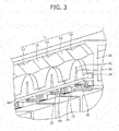
- FIG. 3 is a perspective view of a state that a cover 50 of the vehicular light-emitting device 1 is removed.
- the vehicular light-emitting device 1 mainly includes the cover 50, LED parts 20 serving as light sources, lenses 30 for diffusing and emitting the light entered from the LED parts 20, and a holder 10 (a holding part) which holds the LED parts 20, the lenses 30 and the like. Moreover, in the holder 10, a mirror-finished reflection part 11 consisting of convex parts 12 and planar parts 13 is provided, and the refracted light from the lenses 30 is reflected toward a window part 51 (a light-emitting surface) by the reflection part 11.
- the emitting direction (that is, the side toward a notch part from the LED part 20) of the LED parts 20 is assumed to be forward, the reverse direction thereof is assumed to be backward, the side away from the center of the lenses 30 is assumed to be outside, and the reverse side thereof is assumed to be inside.
- the lens 30 includes a lens body part 31, a notch part 32, a light source introduction part 33, and mounting structure parts 34.
- the notch part 32 is provided in a position which is the center of the lens body part 31 and faces the LED part 20.
- the light source introduction part 33 protrudes to the LED part 20 side in the rear side of the notch part 32, and introduces the incident light from the LED part 20.
- the mounting structure parts 34 are portions which protrude toward the outside from both sides of the lens body part 31 and are for mounting the lens 30 to the holder 10.
- a locking pawl part 35 is provided, and the lens 30 is snap-fit fixed to the holder 10 by the locking pawl part 35.
- the curvature of the notch part 32 is larger.
- the curvature of the front edge portion of the lens body part 31 may be constant or may be not constant. If it is not constant, for example, the curvature of the center of the front edge portion may be smaller than the curvature of the outside of the center.
- each single LED part 20 is arranged in a serial direction with respect to a plurality of lenses 30, and the LED part 20 and the lens 30 arranged in series therewith are formed into a light-emitting unit 100.
- the above serial direction is a direction in which a center axis of the lens 30 and an optical axis of the LED part 20 are parallel (including coincident).
- the light-emitting unit 100 is configured by serially arranging the LED part 20 and the lens 30, thereby the light-emitting unit 100 can be thinned.
- the vehicular light-emitting device 1 By mounting the thinned light-emitting unit 100, the vehicular light-emitting device 1 can be thinned, and therefore the degree of freedom of installation thereof to a vehicle can be increased.
- the vehicular light-emitting device 1 includes a plurality of light-emitting units 100.
- the plurality of light-emitting units 100 are arranged in parallel with a longitudinal direction of the window part 51.
- the convex part 12 is provided at a position facing the light-emitting unit 100 (that is, the LED part 20), and the planar part 13 is provided between positions facing the light-emitting unit 100 and the adjacent light-emitting unit 100 respectively (that is, between the convex part 12 and the convex part 12).
- the reflection direction of light in the reflection part 11 can be adjusted, and further brightness unevenness can be reduced.
- the cover 50 has a shape inclined to the lens 30 side from backward to forward of the lens 30.
- the cover 50 and the lens 30 are located closest to each other in a front end portion of the lens 30.
- the light emitted from the front end portion of the lens 30 can be suppressed from being reflected on the cover 50 and being returned to the rear side than the window part 51.
- brightness of the light emitted from the window part 51 to the exterior of the vehicular light-emitting device 1 can be suppressed from being reduced.
- the window part 51 side of the vehicular light-emitting device 1 is assumed to be the light-emitting surface side, and the opposite side thereof is assumed to be the back surface side.
- the holder 10 has a holder base part region 16, an LED mounting region 17, a lens fixing region 18, and a reflection part forming region 19.
- the holder base part region 16 is a portion extending backward from forward.
- the LED mounting region 17 is a portion which extends to the back surface side in a rear end portion of the holder base part region 16 and to which the LED part 20 is mounted and fixed.
- the lens fixing region 18 is a portion which extends to the light-emitting surface side from the holder base part region 16 and to which the lens 30 is mounted and fixed.
- the reflection part forming region 19 is a portion which extends to both sides of the light-emitting surface side and the back surface side in a front end portion of the holder base part region 16 and in which the reflection part 11 is provided on an inclined surface, which is the light-emitting surface side, facing the lens 30.
- the angle (the inclination) of the reflection surface may be set so that the intensity of the reflection light to the window part 51 from the lens 30 becomes maximum.
- an insertion hole 14 into which the light source introduction part 33 of the lens 30 is inserted, and an insertion hole 15 into which the rear end portion (including the locking pawl part 35) of the mounting structure part 34 of the lens 30 is inserted are provided respectively.
- a control circuit (not shown) is connected, and each light-emitting timing, light-emitting time and the like of the plurality of LED parts 20 are controlled by the control circuit.
- the plurality of LED parts 20 are made to emit light simultaneously, partly, or flowingly right and left, thereby a various lighting effects can be exhibited.
- FIG. 4 shows a relationship between the position in the light-emitting surface on the front side (that is, the position in the width direction of the light-emitting surface) of the single light-emitting unit 100 and the brightness.
- a first brightness peak at a position passing through the center of the notch part 32 from the LED part 20, and further, two brightness peaks (a second brightness peak and a third brightness peak) exist also on the right and left sides of the first brightness peak.
- two brightness peaks (a second brightness peak and a third brightness peak) exist also on the right and left sides of the first brightness peak.
- FIG. 5 shows a relationship between the position in the light-emitting surface on the front side of the plurality of light-emitting units 100 and the brightness.
- the brightness peaks in the light-emitting surface can be at substantially equal intervals.
- the arrangement interval of the light-emitting units 100 even between the positions facing the light-emitting units 100 on the light-emitting surface, peaks exist.
- performance which shows as if there were more light sources than the number of light-emitting units 100 (that is, the number of light sources) is enabled, and brightness unevenness can be reduced.
- brightness unevenness can be further reduced.
- FIG. 6 is a plan view of the vehicular light-emitting device 1A according to the second embodiment.
- FIG. 7 is a cross-sectional view in VII-VII of FIG. 6 . It should be noted that since the light-emitting unit 100 mounted in the vehicular light-emitting device 1A according to the second embodiment is similar to that of the first embodiment, the description thereof will be omitted. In the following, the differences from the first embodiment will be mainly described.
- the structures of a cover 50A and a holder 10A are different from that of the vehicular light-emitting device 1 according to the first embodiment. That is, as shown in FIG. 7 , the second embodiment is different from the first embodiment in that the light-emitting unit 100 and a window part 51A of the cover 50A are arranged in a serial direction, and the reflection part forming region 19 is not provided in the holder 10A.
- the second embodiment is different from the first embodiment in that in a surface between the adjacent light-emitting units 100 which is the light-emitting surface side of a base part (a holder base part region 16A) of the holder 10A, a bowl-shaped concave part 60 is formed.
- the concave part 60 is formed so that the width thereof is gradually reduced from the front end portion of the holder base part region 16A to about a position of the center of the lens 30.
- the reflection direction from the holder 10A side is controlled, and brightness unevenness can be reduced.
- FIG. 8 and FIG. 9 another configuration example of the lens 30 mounted in the vehicular light-emitting device 1 will be described. It should be noted that the example of the lens 30 described below is applicable equally to the vehicular light-emitting device 1A.
- FIG. 8 a configuration example of the lens 30 in a case where a rotation regulating mechanism with respect to the holder 10 is provided in the lens 30 is shown.
- FIG. 8 (A) shows a plan view of the light-emitting unit 100 including the lens 30 fixed to the holder 10
- FIG. 8(B) shows a side view of FIG. 8(A) .
- ribs 36 vertically protruding from the mounting structure part 34 are provided respectively.
- the ribs 36 perform a function of regulating a swinging motion of the lens 30 with respect to the holder 10 by abutment of the ribs 36 of the lens 30 against the lens fixing region 18 of the holder 10.
- the above swinging motion means a rotating motion by which the front end portion of the lens 30 approaches and separates from the holder base part region 16.
- the movement by which the lens 30 is displaced from the initial arrangement with respect to the holder 10 and the LED part 20 can be regulated, and therefore the irradiation direction from the light-emitting unit 100 can be stabilized. Further, since the movement of the lens 30 is regulated, the lens 30 is suppressed from colliding with another member even at vibration of a vehicle, and sounding is also reduced.
- a light-emitting unit group 101 in which the plurality of light-emitting units 100 are connected by connection parts 37 may be mounted to the holder 10.
- FIG. 10 is a plan view of the vehicular light-emitting device 1B according to the third embodiment
- FIG. 11 is a cross-sectional view in XI-XI of FIG. 10 .
- the vehicular light-emitting device 1B mainly includes a cover 50B, the LED parts 20 serving as the light sources, lenses 30B for diffusing and emitting the light entered from the LED parts 20, and a holder 10B (a holding part) which holds the LED parts 20, the lenses 30B and the like. Moreover, in the holder 10B, the mirror-finished reflection part 11 is provided. The reflection part 11 reflects the refracted light from the lenses 30B toward a window part 51B (a light-emitting surface) of the cover 50.
- the lens 30B includes a lens body part 31B, and a notch part 32B provided in a position which is the center of the lens body part 31B and faces the LED part 20. It should be noted that, in the following, the lens 30B and the LED parts 20 arranged in series therewith are formed into a light-emitting unit 100B.
- the cover 50B has a U-shape, and a light-emitting surface forming surface in which the window part 51B is provided, of the cover 50B, and the lens 30B are substantially parallel. Moreover, the length (the length in a direction perpendicular to the arrangement direction of the light-emitting units 100B) in a front to back direction of the light-emitting surface forming surface is longer compared to the first embodiment.
- the window part 51B side of the vehicular light-emitting device 1B is assumed to be the light-emitting surface side, and the opposite side thereof is assumed to be the back surface side.
- the holder 10 has an LED mounting region 17B, a holder base part region 16B, and a reflection part forming region 19B.
- the LED mounting region 17B is a substantially U-shaped portion to which the LED part 20 is mounted and fixed.
- the holder base part region 16B is a portion which supports the lens 30B and extends in substantially parallel with the lens 30B from the LED mounting region 17B.
- the reflection part forming region 19B is a portion extending to the light-emitting surface side from the holder base part region 16B, and is a portion in which the reflection part 11 is provided on an inclined surface, which is the light-emitting surface side, facing the lens 30B.
- the angle (the inclination) of the reflection surface may be set so that the intensity of the reflection light to the window part 51B from the lens 30B becomes maximum.
- a control circuit (not shown) is connected, and each light-emitting timing, light-emitting time and the like of the plurality of LED parts 20 are controlled by the control circuit.
- the lens 30B mounted in the vehicular light-emitting device 1B according to the third embodiment is different from the lens 30 mounted in the vehicular light-emitting device 1 according to the first embodiment in the lens body part 31 (31B), the notch part 32 (32B), and an R-shape thereof. That is, in the third embodiment, the curvature of the lens body part 31B is larger than the curvature of the lens body part 31 in the first embodiment. Moreover, in the third embodiment, the curvature of the notch part 32B is smaller than the curvature of the notch part 32 in the first embodiment. As thus described, by adjusting the R-shape of the lens, as shown in FIG. 12 and FIG. 13 , a diffusion mode of the light from the lens is adjusted, and the pattern of brightness can be changed.
- FIG. 12 shows a relationship between the position in the light-emitting surface on the front side (that is, the position in the width direction of the light-emitting surface) of the single light-emitting unit 100B and the brightness.
- a gentle brightness peak compared to the light-emitting unit 100 according to the first embodiment exists at a position passing through the center of the notch part 32 from the LED part 20. That is, by the lens 30B according to the third embodiment, the diffusion light more reduced in brightness unevenness compared to the lens 30 according to the first embodiment is emitted.
- FIG. 13 shows a relationship between the position in the light-emitting surface on the front side (that is, the position in the width direction of the light-emitting surface) of the plurality of light-emitting units 100B and the brightness.
- the arrangement interval of the light-emitting units 100B is adjusted, and peaks exist even between the positions facing the light-emitting units 100B in the light-emitting surface, thereby capable of reducing brightness unevenness in the light-emitting surface.
- the diffusion mode of the light from the lens is varied.
- the light-emitting unit is miniaturized. Thereby, it is possible to miniaturize the vehicular light-emitting device mounting the light-emitting unit.
- the vehicular light-emitting device suppressed in brightness unevenness can be adapted so as to fit the size of the space demanded by a vehicle.
- the vehicular light-emitting devices according to the first to third embodiments of the present invention have been mainly described.
- the above embodiments are merely an example to facilitate understanding of the present invention, and the present invention is not limited thereto.
- the present invention can be changed and improved without departing from the gist thereof, and as a matter of course, the present invention includes equivalents thereof.
Abstract
Description
- The present invention relates to a vehicular light-emitting device and, more specifically, to a vehicular light-emitting device provided with a plurality of light sources.
- Some vehicular light-emitting devices are provided with a plurality of light sources. Such a vehicular light-emitting device may exhibit a various lighting effects by lighting up the plurality of light sources simultaneously or sequentially.
- For example, in the following
Patent Literature 1, in a vehicular light-emitting device provided with a plurality of LEDs, in order to suppress brightness unevenness from being generated in the emitted light from the LED, a structure for reflecting the light from each LED and diffusing the light widely is provided. - PATENT LITERATURE 1:
JP 2012-17063 A - In order to suppress brightness unevenness of the plurality of light sources, if the lights from the plurality of light sources are reflected and mixed, there is a fear that which light source is lightened up is ambiguous and the performance property of illumination is reduced. On the other hand, if the number of the light sources is increased, there are problems in terms of power consumption and cost.
- The present invention has been made in view of the above problems, and an object of the present invention is to provide a vehicular light-emitting device enabling performance which shows as if there were more light sources than the actual number of light sources, and capable of reducing brightness unevenness.
- The problems are solved by a vehicular light-emitting device in which a plurality of light-emitting units, each of which includes a light source and a lens for diffusing and emitting the light entered from the light source, are arranged side by side, and one or more brightness peak values exist between the plurality of light-emitting units.
- In the above vehicular light-emitting device, even between the plurality of light-emitting units, each of which includes the light source, one or more brightness peaks exist, thereby enabling performance which shows as if there were more light sources than the actual number of light sources, and capable of reducing brightness unevenness.
- In the above vehicular light-emitting device, the light emitted from the lenses of the light-emitting units has a plurality of brightness peaks with respect to the spreading direction of the light, and the arrangement interval of the plurality of light-emitting units may be set so that the plurality of brightness peaks of the light emitted from the plurality of light-emitting units are aligned at substantially equal intervals. Thereby, the plurality of brightness peaks of the light irradiated from the plurality of light-emitting units are at substantially equal intervals, and therefore brightness unevenness can be further reduced.
- In the above vehicular light-emitting device, a holding part which holds the plurality of light-emitting units is included, and the holding part may have a reflection part which reflects the light emitted from the lenses toward a light-emitting surface. Thereby, the irradiation direction of the light can be adjusted.
- In the above vehicular light-emitting device, the reflection part may be formed with a convex part at a position facing the light source. Thereby, the reflection direction of the light at the reflection part can be adjusted, and further brightness unevenness also can be reduced.
- In the above vehicular light-emitting device, the holding part may be formed with a concave part between the regions which hold the plurality of light-emitting units. Thereby, the reflection direction from the holding part side is controlled, and brightness unevenness can be reduced.
- In the above vehicular light-emitting device, a cover which engages with the holding part and covers the plurality of light-emitting units is included, and the cover may have such a shape that at an end portion on the emission side of the light in the lens, the distance with the lens is nearest. Thereby, the light can be prevented from diffusing to the cover side.
- In the above vehicular light-emitting device, the lens has locking pawl parts at both ends, and may be snap-fixed to the holding part by the locking pawl parts. Thereby, the lens can be stably mounted to the holding part.
- In the above vehicular light-emitting device, the lens may be formed with a rib which regulates rotation with respect to the holding part. Thereby, rotation of the lens with respect to the holding part is regulated, and therefore the irradiation direction of the light can be stabilized. Further, movement of the lens at vibration of a vehicle is also regulated, and therefore the generation of sounds due to a collision of the lens with another member is also regulated.
- In the above vehicular light-emitting device, the lens may be formed with a notch in a position facing the light source. Thereby, the light entering the lens can be refracted in the spreading direction.
- In the above vehicular light-emitting device, the lenses may have light source introduction parts provided on both sides of the notches and protruded to the light source side. Thereby, the position of the light source with respect to the lens is easy to define, and therefore positioning accuracy of the light source and the lens can be improved.
- According to the present invention, performance which shows as if there were more light sources than the actual number of light sources is enabled, and brightness unevenness can be reduced.
- According to one aspect of the present invention, the plurality of brightness peaks of the light irradiated from the plurality of light-emitting units are at substantially equal intervals, and therefore brightness unevenness can be further reduced.
- According to one aspect of the present invention, the irradiation direction of the light can be adjusted.
- According to one aspect of the present invention, the reflection direction of the light at the reflection part can be adjusted, and further brightness unevenness also can be reduced.
- According to one aspect of the present invention, the reflection direction from the holding part side is controlled, and brightness unevenness can be reduced.
- According to one aspect of the present invention, the light can be prevented from diffusing to the cover side.
- According to one aspect of the present invention, the lens can be stably mounted to the holding part.
- According to one aspect of the present invention, rotation of the lens with respect to the holding part is regulated, and therefore the irradiation direction of the light can be stabilized.
- According to one aspect of the present invention, the light entering the lens can be refracted in the spreading direction.
- According to one aspect of the present invention, the position of the light source with respect to the lens is easy to define, and therefore positioning accuracy of the light source and the lens can be improved.
-
-
FIG. 1 is a plan view of a vehicular light-emitting device according to a first embodiment. -
FIG. 2 is a cross-sectional view in II-II ofFIG. 1 . -
FIG. 3 is a perspective view of a state that a cover of the vehicular light-emitting device according to the first embodiment is removed. -
FIG. 4 is a view showing the characteristics of brightness peak of a light-emitting unit in the vehicular light-emitting device according to the first embodiment. -
FIG. 5 is a view showing the characteristics of brightness peaks of a plurality of light-emitting units, of which arrangement interval is set, in the vehicular light-emitting device according to the first embodiment. -
FIG. 6 is a plan view of a vehicular light-emitting device according to a second embodiment. -
FIG. 7 is a cross-sectional view in VII-VII ofFIG. 7 . -
FIG. 8 shows a configuration example of a lens in a case where a rotation regulating mechanism is provided, (A) is a plan view of the light-emitting unit including the lens, and (B) is a side view of (A). -
FIG. 9 is a view illustrating a shape of a light-emitting unit group in which the plurality of light-emitting units are connected. -
FIG. 10 is a plan view of a vehicular light-emitting device according to a third embodiment. -
FIG. 11 is a cross-sectional view in XI-XI ofFIG. 10 . -
FIG. 12 is a view showing the characteristics of brightness peak of the light-emitting unit according to the third embodiment. -
FIG. 13 is a view showing the characteristics of brightness peaks of the plurality of light-emitting units, of which arrangement interval is set, in the vehicular light-emitting device according to the third embodiment. - Hereinafter, a vehicular light-emitting device according to embodiments of the present invention will be described with reference to
FIG. 1 to FIG. 13 . - The present embodiment relates to an invention of a vehicular light-emitting device in which a plurality of light-emitting units, each of which includes a light source and a lens for diffusing and emitting the light entered from the light source, are arranged side by side, and even between the plurality of light-emitting units, one or more brightness peak values exist.
- <First Embodiment>
- Firstly, based on
FIG. 1 to FIG. 5 , a vehicular light-emitting device 1 according to a first embodiment of the present invention will be described. -
FIG. 1 is a plan view of the vehicular light-emitting device 1 according to the first embodiment.FIG. 2 is a cross-sectional view in II-II ofFIG. 1 .FIG. 3 is a perspective view of a state that acover 50 of the vehicular light-emittingdevice 1 is removed. - As shown in
FIG. 1 , the vehicular light-emittingdevice 1 mainly includes thecover 50,LED parts 20 serving as light sources,lenses 30 for diffusing and emitting the light entered from theLED parts 20, and a holder 10 (a holding part) which holds theLED parts 20, thelenses 30 and the like. Moreover, in theholder 10, a mirror-finished reflection part 11 consisting ofconvex parts 12 andplanar parts 13 is provided, and the refracted light from thelenses 30 is reflected toward a window part 51 (a light-emitting surface) by thereflection part 11. It should be noted that, in the following, the emitting direction (that is, the side toward a notch part from the LED part 20) of theLED parts 20 is assumed to be forward, the reverse direction thereof is assumed to be backward, the side away from the center of thelenses 30 is assumed to be outside, and the reverse side thereof is assumed to be inside. - As shown in
FIG. 1 , thelens 30 includes alens body part 31, anotch part 32, a lightsource introduction part 33, and mountingstructure parts 34. - The
notch part 32 is provided in a position which is the center of thelens body part 31 and faces theLED part 20. - The light
source introduction part 33 protrudes to theLED part 20 side in the rear side of thenotch part 32, and introduces the incident light from theLED part 20. - The mounting
structure parts 34 are portions which protrude toward the outside from both sides of thelens body part 31 and are for mounting thelens 30 to theholder 10. - In addition, in a rear side end portion of the mounting
structure part 34, a lockingpawl part 35 is provided, and thelens 30 is snap-fit fixed to theholder 10 by the lockingpawl part 35. - Here, as shown in
FIG. 1 , with respect to the curvature (for example, a mean curvature) of a front edge portion of thelens body part 31, the curvature of thenotch part 32 is larger. It should be noted that the curvature of the front edge portion of thelens body part 31 may be constant or may be not constant. If it is not constant, for example, the curvature of the center of the front edge portion may be smaller than the curvature of the outside of the center. - Moreover, as shown in
FIG. 1 to FIG. 3 , eachsingle LED part 20 is arranged in a serial direction with respect to a plurality oflenses 30, and theLED part 20 and thelens 30 arranged in series therewith are formed into a light-emittingunit 100. The above serial direction is a direction in which a center axis of thelens 30 and an optical axis of theLED part 20 are parallel (including coincident). - As thus described, the light-emitting
unit 100 is configured by serially arranging theLED part 20 and thelens 30, thereby the light-emittingunit 100 can be thinned. - By mounting the thinned light-emitting
unit 100, the vehicular light-emittingdevice 1 can be thinned, and therefore the degree of freedom of installation thereof to a vehicle can be increased. - As shown in
FIG. 1 , the vehicular light-emittingdevice 1 includes a plurality of light-emittingunits 100. The plurality of light-emittingunits 100 are arranged in parallel with a longitudinal direction of thewindow part 51. Here, as shown inFIG. 1 andFIG. 3 , in thereflection part 11, theconvex part 12 is provided at a position facing the light-emitting unit 100 (that is, the LED part 20), and theplanar part 13 is provided between positions facing the light-emittingunit 100 and the adjacent light-emittingunit 100 respectively (that is, between theconvex part 12 and the convex part 12). In this way, the reflection direction of light in thereflection part 11 can be adjusted, and further brightness unevenness can be reduced. - As shown in
FIG. 2 , thecover 50 has a shape inclined to thelens 30 side from backward to forward of thelens 30. In particular, thecover 50 and thelens 30 are located closest to each other in a front end portion of thelens 30. Thereby, the light emitted from the front end portion of thelens 30 can be suppressed from being reflected on thecover 50 and being returned to the rear side than thewindow part 51. Thereby, brightness of the light emitted from thewindow part 51 to the exterior of the vehicular light-emittingdevice 1 can be suppressed from being reduced. It should be noted that, in the following, thewindow part 51 side of the vehicular light-emittingdevice 1 is assumed to be the light-emitting surface side, and the opposite side thereof is assumed to be the back surface side. - Moreover, as shown in
FIG. 2 , theholder 10 has a holderbase part region 16, anLED mounting region 17, alens fixing region 18, and a reflectionpart forming region 19. - The holder
base part region 16 is a portion extending backward from forward. TheLED mounting region 17 is a portion which extends to the back surface side in a rear end portion of the holderbase part region 16 and to which theLED part 20 is mounted and fixed. Thelens fixing region 18 is a portion which extends to the light-emitting surface side from the holderbase part region 16 and to which thelens 30 is mounted and fixed. The reflectionpart forming region 19 is a portion which extends to both sides of the light-emitting surface side and the back surface side in a front end portion of the holderbase part region 16 and in which thereflection part 11 is provided on an inclined surface, which is the light-emitting surface side, facing thelens 30. - Here, the angle (the inclination) of the reflection surface may be set so that the intensity of the reflection light to the
window part 51 from thelens 30 becomes maximum. - Moreover, as shown in
FIG. 3 , in thelens fixing region 18 of theholder 10, aninsertion hole 14 into which the lightsource introduction part 33 of thelens 30 is inserted, and aninsertion hole 15 into which the rear end portion (including the locking pawl part 35) of the mountingstructure part 34 of thelens 30 is inserted are provided respectively. - Moreover, to the
LED part 20, a control circuit (not shown) is connected, and each light-emitting timing, light-emitting time and the like of the plurality ofLED parts 20 are controlled by the control circuit. Thereby, the plurality ofLED parts 20 are made to emit light simultaneously, partly, or flowingly right and left, thereby a various lighting effects can be exhibited. - Next, based on
FIG. 4 andFIG. 5 , the brightness characteristics of the light-emittingunit 100 and the brightness characteristics of the plurality of light-emittingunits 100 included in the vehicular light-emittingdevice 1 according to the first embodiment will be described. - In
FIG. 4 , the brightness characteristics of the single light-emittingunit 100 are shown.FIG. 4 shows a relationship between the position in the light-emitting surface on the front side (that is, the position in the width direction of the light-emitting surface) of the single light-emittingunit 100 and the brightness. - As shown in
FIG. 4 , in the light-emittingunit 100, there is a first brightness peak at a position passing through the center of thenotch part 32 from theLED part 20, and further, two brightness peaks (a second brightness peak and a third brightness peak) exist also on the right and left sides of the first brightness peak. As thus described, depending on the shape (in particular, the size and the curvature) of thelens body part 31 of thelens 30 and the shape (in particular, the size and the curvature) of thenotch part 32, a plurality of brightness peaks will appear in the spreading direction of the light emitted from the light-emittingunit 100. - Moreover, in
FIG. 5 , the brightness characteristics in a case where the plurality of light-emittingunits 100 are arranged in a predetermined arrangement interval (D) are shown.FIG. 5 shows a relationship between the position in the light-emitting surface on the front side of the plurality of light-emittingunits 100 and the brightness. - As shown in
FIG. 5 , by adjusting the arrangement interval of the light-emittingunits 100, the brightness peaks in the light-emitting surface can be at substantially equal intervals. As thus described, by adjusting the arrangement interval of the light-emittingunits 100, even between the positions facing the light-emittingunits 100 on the light-emitting surface, peaks exist. Thereby, performance which shows as if there were more light sources than the number of light-emitting units 100 (that is, the number of light sources) is enabled, and brightness unevenness can be reduced. Moreover, by setting the brightness peaks at substantially equal intervals, brightness unevenness can be further reduced. - Next, based on
FIG. 6 and FIG. 7 , a vehicular light-emittingdevice 1A according to a second embodiment of the present invention will be described. -
FIG. 6 is a plan view of the vehicular light-emittingdevice 1A according to the second embodiment.FIG. 7 is a cross-sectional view in VII-VII ofFIG. 6 . It should be noted that since the light-emittingunit 100 mounted in the vehicular light-emittingdevice 1A according to the second embodiment is similar to that of the first embodiment, the description thereof will be omitted. In the following, the differences from the first embodiment will be mainly described. - As shown in
FIG. 6 and FIG. 7 , in the vehicular light-emittingdevice 1A according to the second embodiment, the structures of acover 50A and aholder 10A are different from that of the vehicular light-emittingdevice 1 according to the first embodiment. That is, as shown inFIG. 7 , the second embodiment is different from the first embodiment in that the light-emittingunit 100 and awindow part 51A of thecover 50A are arranged in a serial direction, and the reflectionpart forming region 19 is not provided in theholder 10A. Furthermore, the second embodiment is different from the first embodiment in that in a surface between the adjacent light-emittingunits 100 which is the light-emitting surface side of a base part (a holderbase part region 16A) of theholder 10A, a bowl-shapedconcave part 60 is formed. In addition, theconcave part 60 is formed so that the width thereof is gradually reduced from the front end portion of the holderbase part region 16A to about a position of the center of thelens 30. - As described above, by forming the bowl-shaped
concave part 60 in the holderbase part region 16A, the reflection direction from theholder 10A side is controlled, and brightness unevenness can be reduced. - Here, based on
FIG. 8 andFIG. 9 , another configuration example of thelens 30 mounted in the vehicular light-emittingdevice 1 will be described. It should be noted that the example of thelens 30 described below is applicable equally to the vehicular light-emittingdevice 1A. - In
FIG. 8 , a configuration example of thelens 30 in a case where a rotation regulating mechanism with respect to theholder 10 is provided in thelens 30 is shown.FIG. 8 (A) shows a plan view of the light-emittingunit 100 including thelens 30 fixed to theholder 10, andFIG. 8(B) shows a side view ofFIG. 8(A) . As shown inFIGS. 8(A) and (B) , on both surfaces of the mountingstructure part 34 in thelens 30 of the light-emittingunit 100,ribs 36 vertically protruding from the mountingstructure part 34 are provided respectively. - As shown in
FIG. 8(B) , theribs 36 perform a function of regulating a swinging motion of thelens 30 with respect to theholder 10 by abutment of theribs 36 of thelens 30 against thelens fixing region 18 of theholder 10. It should be noted that the above swinging motion means a rotating motion by which the front end portion of thelens 30 approaches and separates from the holderbase part region 16. - Thereby, the movement by which the
lens 30 is displaced from the initial arrangement with respect to theholder 10 and theLED part 20 can be regulated, and therefore the irradiation direction from the light-emittingunit 100 can be stabilized. Further, since the movement of thelens 30 is regulated, thelens 30 is suppressed from colliding with another member even at vibration of a vehicle, and sounding is also reduced. - In the above embodiments, although the example of the structure in which the single light-emitting
unit 100 is mounted to theholder 10 has been described, as shown inFIG. 9 , a light-emittingunit group 101 in which the plurality of light-emittingunits 100 are connected byconnection parts 37 may be mounted to theholder 10. - Next, based on
FIGS. 10 to 13 , a vehicular light-emittingdevice 1B according to a third embodiment of the present invention will be described. -
FIG. 10 is a plan view of the vehicular light-emittingdevice 1B according to the third embodiment, andFIG. 11 is a cross-sectional view in XI-XI ofFIG. 10 . - As shown in
FIG. 10 , the vehicular light-emittingdevice 1B according to the third embodiment mainly includes acover 50B, theLED parts 20 serving as the light sources,lenses 30B for diffusing and emitting the light entered from theLED parts 20, and aholder 10B (a holding part) which holds theLED parts 20, thelenses 30B and the like. Moreover, in theholder 10B, the mirror-finished reflection part 11 is provided. Thereflection part 11 reflects the refracted light from thelenses 30B toward awindow part 51B (a light-emitting surface) of thecover 50. - As shown in
FIG. 10 , thelens 30B includes alens body part 31B, and anotch part 32B provided in a position which is the center of thelens body part 31B and faces theLED part 20. It should be noted that, in the following, thelens 30B and theLED parts 20 arranged in series therewith are formed into a light-emittingunit 100B. - As shown in
FIG. 11 , thecover 50B has a U-shape, and a light-emitting surface forming surface in which thewindow part 51B is provided, of thecover 50B, and thelens 30B are substantially parallel. Moreover, the length (the length in a direction perpendicular to the arrangement direction of the light-emittingunits 100B) in a front to back direction of the light-emitting surface forming surface is longer compared to the first embodiment. In the following, thewindow part 51B side of the vehicular light-emittingdevice 1B is assumed to be the light-emitting surface side, and the opposite side thereof is assumed to be the back surface side. - Moreover, as shown in
FIG. 11 , theholder 10 has anLED mounting region 17B, a holderbase part region 16B, and a reflectionpart forming region 19B. - The
LED mounting region 17B is a substantially U-shaped portion to which theLED part 20 is mounted and fixed. The holderbase part region 16B is a portion which supports thelens 30B and extends in substantially parallel with thelens 30B from theLED mounting region 17B. The reflectionpart forming region 19B is a portion extending to the light-emitting surface side from the holderbase part region 16B, and is a portion in which thereflection part 11 is provided on an inclined surface, which is the light-emitting surface side, facing thelens 30B. Here, the angle (the inclination) of the reflection surface may be set so that the intensity of the reflection light to thewindow part 51B from thelens 30B becomes maximum. - Moreover, to the
LED part 20, a control circuit (not shown) is connected, and each light-emitting timing, light-emitting time and the like of the plurality ofLED parts 20 are controlled by the control circuit. - Here, as shown in
FIG. 10 , thelens 30B mounted in the vehicular light-emittingdevice 1B according to the third embodiment is different from thelens 30 mounted in the vehicular light-emittingdevice 1 according to the first embodiment in the lens body part 31 (31B), the notch part 32 (32B), and an R-shape thereof. That is, in the third embodiment, the curvature of thelens body part 31B is larger than the curvature of thelens body part 31 in the first embodiment. Moreover, in the third embodiment, the curvature of thenotch part 32B is smaller than the curvature of thenotch part 32 in the first embodiment. As thus described, by adjusting the R-shape of the lens, as shown inFIG. 12 andFIG. 13 , a diffusion mode of the light from the lens is adjusted, and the pattern of brightness can be changed. - In
FIG. 12 , the brightness characteristics of the single light-emittingunit 100B according to the third embodiment are shown.FIG. 12 shows a relationship between the position in the light-emitting surface on the front side (that is, the position in the width direction of the light-emitting surface) of the single light-emittingunit 100B and the brightness. - As shown in
FIG. 12 , in the light-emittingunit 100B, a gentle brightness peak compared to the light-emittingunit 100 according to the first embodiment exists at a position passing through the center of thenotch part 32 from theLED part 20. That is, by thelens 30B according to the third embodiment, the diffusion light more reduced in brightness unevenness compared to thelens 30 according to the first embodiment is emitted. - Moreover, in
FIG. 13 , the brightness characteristics in a case where the plurality of light-emittingunits 100B according to the third embodiment are arranged in a predetermined arrangement interval (d) are shown.FIG. 13 shows a relationship between the position in the light-emitting surface on the front side (that is, the position in the width direction of the light-emitting surface) of the plurality of light-emittingunits 100B and the brightness. - As shown in
FIG. 13 , by adjusting the arrangement interval of the light-emittingunits 100B, even between the positions facing the light-emittingunits 100B, peaks exist. As thus described, the arrangement interval of the light-emittingunits 100B is adjusted, and peaks exist even between the positions facing the light-emittingunits 100B in the light-emitting surface, thereby capable of reducing brightness unevenness in the light-emitting surface. - As described above, with respect to the light-emitting unit mounted in the vehicular light-emitting device, by changing the R-shape of the lens for diffusing the light entered from the LED part, the diffusion mode of the light from the lens is varied.
- For example, in the vehicular light-emitting
device 1 according to the first embodiment, by reducing the curvature of the outer periphery of the lens than the lens according to the third embodiment, the light-emitting unit is miniaturized. Thereby, it is possible to miniaturize the vehicular light-emitting device mounting the light-emitting unit. - As thus described, by setting the R-shape of the lens, the vehicular light-emitting device suppressed in brightness unevenness can be adapted so as to fit the size of the space demanded by a vehicle.
- Hereinbefore, the vehicular light-emitting devices according to the first to third embodiments of the present invention have been mainly described. However, the above embodiments are merely an example to facilitate understanding of the present invention, and the present invention is not limited thereto. The present invention can be changed and improved without departing from the gist thereof, and as a matter of course, the present invention includes equivalents thereof.
-
- 1, 1A, 1B: Vehicular light-emitting device
- 10, 10A, 10B: Holder
- 11: Reflection part
- 12: Convex part
- 13: Planar part
- 14, 15: Insertion hole
- 16, 16A, 16B: Holder base part region
- 17, 17A, 17B: LED mounting region
- 18: Lens fixing region
- 19, 19B: Reflection part forming region
- 20: LED part
- 30, 30B: Lens
- 31, 31B: Lens body part
- 32, 32B: Notch part
- 33: Light source introduction part
- 34: Mounting structure part
- 35: Locking pawl part
- 36: Rib
- 37: Connection part
- 50, 50A, 50B: Cover
- 51, 51A, 51B: Window part
- 60: Concave part
- 100, 100B: Light-emitting unit
- 101: Light-emitting unit group
Claims (10)
- A vehicular light-emitting device wherein
a plurality of light-emitting units, each of which includes a light source and a lens for diffusing and emitting the light entered from the light source, are arranged side by side, and
one or more brightness peak values exist between the plurality of light-emitting units. - The vehicular light-emitting device according to claim 1, wherein
the light emitted from the lenses of the light-emitting units has a plurality of brightness peaks with respect to the spreading direction of the light, and
the arrangement interval of the plurality of light-emitting units is set so that the plurality of brightness peaks of the light emitted from the plurality of light-emitting units are aligned at substantially equal intervals. - The vehicular light-emitting device according to claim 1, comprising a holding part which holds the plurality of light-emitting units,
wherein the holding part has a reflection part which reflects the light emitted from the lenses toward a light-emitting surface. - The vehicular light-emitting device according to claim 3, wherein the reflection part is formed with a convex part at a position facing the light source.
- The vehicular light-emitting device according to claim 3, wherein the holding part is formed with a concave part between the regions which hold the plurality of light-emitting units.
- The vehicular light-emitting device according to claim 3, comprising a cover which engages with the holding part and covers the plurality of light-emitting units,
wherein the cover has such a shape that at an end portion on the emission side of the light in the lens, the distance with the lens is nearest. - The vehicular light-emitting device according to claim 3, wherein the lens has locking pawl parts at both ends, and is snap-fixed to the holding part by the locking pawl parts.
- The vehicular light-emitting device according to claim 3, wherein the lens is formed with a rib which regulates rotation with respect to the holding part.
- The vehicular light-emitting device according to claim 1, wherein the lens is formed with a notch in a position facing the light source.
- The vehicular light-emitting device according to claim 9, wherein the lenses have light source introduction parts provided on both sides of the notches and protruded to the light source side.
Applications Claiming Priority (2)
| Application Number | Priority Date | Filing Date | Title |
|---|---|---|---|
| JP2015150057A JP6575204B2 (en) | 2015-07-29 | 2015-07-29 | Light emitting device for vehicle |
| PCT/JP2016/072215 WO2017018490A1 (en) | 2015-07-29 | 2016-07-28 | Vehicular light-emitting device |
Publications (3)
| Publication Number | Publication Date |
|---|---|
| EP3330595A1 true EP3330595A1 (en) | 2018-06-06 |
| EP3330595A4 EP3330595A4 (en) | 2018-07-25 |
| EP3330595B1 EP3330595B1 (en) | 2021-11-17 |
Family
ID=57884404
Family Applications (1)
| Application Number | Title | Priority Date | Filing Date |
|---|---|---|---|
| EP16830595.1A Active EP3330595B1 (en) | 2015-07-29 | 2016-07-28 | Vehicular light-emitting device |
Country Status (5)
| Country | Link |
|---|---|
| US (2) | US10654405B2 (en) |
| EP (1) | EP3330595B1 (en) |
| JP (1) | JP6575204B2 (en) |
| CN (1) | CN107923588B (en) |
| WO (1) | WO2017018490A1 (en) |
Cited By (1)
| Publication number | Priority date | Publication date | Assignee | Title |
|---|---|---|---|---|
| US10443806B2 (en) * | 2016-12-22 | 2019-10-15 | Flex-N-Gate Advanced Product Development, Inc. | Homogenous LED vehicle lamp |
Family Cites Families (25)
| Publication number | Priority date | Publication date | Assignee | Title |
|---|---|---|---|---|
| JPH0745802Y2 (en) * | 1990-07-30 | 1995-10-18 | 株式会社三協精機製作所 | Image recognition device |
| JP3897411B2 (en) * | 1997-09-02 | 2007-03-22 | キヤノン株式会社 | Flash device and camera having the flash device |
| JP3986779B2 (en) * | 2001-08-15 | 2007-10-03 | 株式会社小糸製作所 | Vehicle lighting |
| JP2003059313A (en) * | 2001-08-15 | 2003-02-28 | Koito Mfg Co Ltd | Vehicule lighting device |
| JP2003086007A (en) * | 2001-09-10 | 2003-03-20 | Oshima Denki Seisakusho:Kk | Lamp for vehicle |
| JP3953764B2 (en) | 2001-09-20 | 2007-08-08 | 株式会社小糸製作所 | Vehicle lighting |
| JP4027688B2 (en) * | 2002-03-15 | 2007-12-26 | 株式会社小糸製作所 | Vehicle lighting |
| US7237925B2 (en) * | 2004-02-18 | 2007-07-03 | Lumination Llc | Lighting apparatus for creating a substantially homogenous lit appearance |
| US20060044806A1 (en) * | 2004-08-25 | 2006-03-02 | Abramov Vladimir S | Light emitting diode system packages |
| US7275849B2 (en) * | 2005-02-25 | 2007-10-02 | Visteon Global Technologies, Inc. | LED replacement bulb |
| GB2464102A (en) * | 2008-10-01 | 2010-04-07 | Optovate Ltd | Illumination apparatus comprising multiple monolithic subarrays |
| US8083380B2 (en) * | 2009-04-17 | 2011-12-27 | Mig Technology Inc. | Integrated structure for optical refractor |
| US7959322B2 (en) * | 2009-04-24 | 2011-06-14 | Whelen Engineering Company, Inc. | Optical system for LED array |
| CN102498327B (en) * | 2009-06-15 | 2015-09-23 | 夏普株式会社 | Light emitting module, lighting device, display unit and radiovisor |
| JP2012017063A (en) | 2010-07-09 | 2012-01-26 | Toyota Boshoku Corp | Lighting system for vehicle |
| CN102844618B (en) * | 2010-12-01 | 2014-12-31 | 纳卢克斯株式会社 | Optical element and lighting device using the same |
| JP2012145829A (en) * | 2011-01-13 | 2012-08-02 | Sharp Corp | Light-emitting device and luminaire |
| JP2012243493A (en) * | 2011-05-18 | 2012-12-10 | Stanley Electric Co Ltd | Vehicular signal lamp |
| WO2013081417A1 (en) * | 2011-12-02 | 2013-06-06 | Seoul Semiconductor Co., Ltd. | Light emitting module and lens |
| US9194566B2 (en) | 2012-06-08 | 2015-11-24 | Lg Innotek Co., Ltd. | Lamp unit and vehicle lamp apparatus using the same |
| KR102024291B1 (en) * | 2012-12-18 | 2019-09-23 | 엘지이노텍 주식회사 | Lamp unit and vehicle lamp apparatus for using the same |
| KR101490347B1 (en) * | 2013-04-16 | 2015-02-11 | 한국광기술원 | Lighting lens module |
| JP2015002032A (en) * | 2013-06-14 | 2015-01-05 | 株式会社朝日ラバー | Translucent waterproof cover lens |
| WO2015004910A1 (en) * | 2013-07-10 | 2015-01-15 | パナソニックIpマネジメント株式会社 | Lighting apparatus and automobile having lighting apparatus mounted therein |
| DE102013110344B4 (en) * | 2013-09-19 | 2022-09-01 | HELLA GmbH & Co. KGaA | Lighting device for vehicles for generating tail light and rear fog light functions |
-
2015
- 2015-07-29 JP JP2015150057A patent/JP6575204B2/en active Active
-
2016
- 2016-07-28 EP EP16830595.1A patent/EP3330595B1/en active Active
- 2016-07-28 CN CN201680037234.0A patent/CN107923588B/en active Active
- 2016-07-28 WO PCT/JP2016/072215 patent/WO2017018490A1/en active Application Filing
- 2016-07-28 US US15/747,350 patent/US10654405B2/en active Active
-
2020
- 2020-04-30 US US16/863,021 patent/US11320109B2/en active Active
Cited By (1)
| Publication number | Priority date | Publication date | Assignee | Title |
|---|---|---|---|---|
| US10443806B2 (en) * | 2016-12-22 | 2019-10-15 | Flex-N-Gate Advanced Product Development, Inc. | Homogenous LED vehicle lamp |
Also Published As
| Publication number | Publication date |
|---|---|
| WO2017018490A1 (en) | 2017-02-02 |
| JP6575204B2 (en) | 2019-09-18 |
| CN107923588B (en) | 2020-09-29 |
| US11320109B2 (en) | 2022-05-03 |
| EP3330595A4 (en) | 2018-07-25 |
| US20200326050A1 (en) | 2020-10-15 |
| CN107923588A (en) | 2018-04-17 |
| EP3330595B1 (en) | 2021-11-17 |
| US20180215310A1 (en) | 2018-08-02 |
| JP2017033677A (en) | 2017-02-09 |
| US10654405B2 (en) | 2020-05-19 |
Similar Documents
| Publication | Publication Date | Title |
|---|---|---|
| EP1970616B1 (en) | Vehicle lamp | |
| CN108603648B (en) | Lamp and vehicle with lamp | |
| US9328885B2 (en) | Vehicle lighting unit | |
| US8851721B2 (en) | Hybrid projector LED low beam headlamp | |
| EP2143991A2 (en) | Lamp | |
| CN105423209B (en) | vehicle lighting device using multi-source optical lens | |
| JP6036493B2 (en) | Linear lighting device | |
| US11668445B2 (en) | Multi-beam vehicle light | |
| JP2020009673A (en) | Vehicular lighting fixture | |
| EP2484553B1 (en) | Vehicle lamp and optical unit thereof | |
| EP3135989A1 (en) | Vehicle light guide and vehicle lamp | |
| EP3330595B1 (en) | Vehicular light-emitting device | |
| CN105473935B (en) | Lighting system, motor vehicle lighting component and motor vehicle | |
| JP5987681B2 (en) | Linear lighting device | |
| KR20110055914A (en) | Led optical device for head lamp | |
| JP6003178B2 (en) | Vehicle lighting | |
| JP2020205147A (en) | Light guide body and vehicular lighting fixture | |
| JP2019197743A (en) | Vehicular light emitting device | |
| JP2017183143A (en) | Vehicular lighting tool | |
| CN114026361A (en) | Maintaining collimator elements in lighting devices | |
| CN112555769B (en) | Lighting device | |
| JP2021073676A (en) | Vehicular light emitting device | |
| CN110207070A (en) | Light guide member, car light and motor vehicles | |
| EP3578877B1 (en) | Vehicular lamp | |
| JP2017211628A (en) | Lens, and vehicle lighting apparatus structure equipped with the lens |
Legal Events
| Date | Code | Title | Description |
|---|---|---|---|
| STAA | Information on the status of an ep patent application or granted ep patent |
Free format text: STATUS: THE INTERNATIONAL PUBLICATION HAS BEEN MADE |
|
| PUAI | Public reference made under article 153(3) epc to a published international application that has entered the european phase |
Free format text: ORIGINAL CODE: 0009012 |
|
| STAA | Information on the status of an ep patent application or granted ep patent |
Free format text: STATUS: REQUEST FOR EXAMINATION WAS MADE |
|
| 17P | Request for examination filed |
Effective date: 20180222 |
|
| AK | Designated contracting states |
Kind code of ref document: A1 Designated state(s): AL AT BE BG CH CY CZ DE DK EE ES FI FR GB GR HR HU IE IS IT LI LT LU LV MC MK MT NL NO PL PT RO RS SE SI SK SM TR |
|
| AX | Request for extension of the european patent |
Extension state: BA ME |
|
| A4 | Supplementary search report drawn up and despatched |
Effective date: 20180627 |
|
| RIC1 | Information provided on ipc code assigned before grant |
Ipc: F21Y 103/10 20160101ALN20180621BHEP Ipc: F21Y 115/10 20160101AFI20180621BHEP Ipc: F21S 43/15 20180101ALI20180621BHEP Ipc: F21S 43/19 20180101ALI20180621BHEP Ipc: F21S 43/20 20180101ALI20180621BHEP Ipc: F21S 43/31 20180101ALI20180621BHEP Ipc: F21S 43/14 20180101ALI20180621BHEP |
|
| DAV | Request for validation of the european patent (deleted) | ||
| DAX | Request for extension of the european patent (deleted) | ||
| STAA | Information on the status of an ep patent application or granted ep patent |
Free format text: STATUS: EXAMINATION IS IN PROGRESS |
|
| 17Q | First examination report despatched |
Effective date: 20200706 |
|
| STAA | Information on the status of an ep patent application or granted ep patent |
Free format text: STATUS: EXAMINATION IS IN PROGRESS |
|
| RIC1 | Information provided on ipc code assigned before grant |
Ipc: F21S 43/31 20180101ALI20210215BHEP Ipc: F21S 43/19 20180101AFI20210215BHEP Ipc: F21S 41/20 20180101ALI20210215BHEP Ipc: F21S 43/40 20180101ALI20210215BHEP Ipc: F21S 43/15 20180101ALI20210215BHEP Ipc: F21V 5/00 20180101ALN20210215BHEP Ipc: F21S 43/14 20180101ALI20210215BHEP Ipc: F21Y 115/10 20160101ALN20210215BHEP Ipc: F21Y 103/10 20160101ALN20210215BHEP Ipc: F21S 41/148 20180101ALI20210215BHEP Ipc: F21S 41/36 20180101ALI20210215BHEP Ipc: F21S 43/20 20180101ALI20210215BHEP Ipc: F21S 41/151 20180101ALI20210215BHEP |
|
| RIC1 | Information provided on ipc code assigned before grant |
Ipc: F21S 43/19 20180101AFI20210311BHEP Ipc: F21S 43/14 20180101ALI20210311BHEP Ipc: F21S 43/15 20180101ALI20210311BHEP Ipc: F21S 43/20 20180101ALI20210311BHEP Ipc: F21S 43/31 20180101ALI20210311BHEP Ipc: F21S 43/40 20180101ALI20210311BHEP Ipc: F21Y 103/10 20160101ALN20210311BHEP Ipc: F21V 5/00 20180101ALN20210311BHEP Ipc: F21Y 115/10 20160101ALN20210311BHEP |
|
| REG | Reference to a national code |
Ref country code: DE Ref legal event code: R079 Ref document number: 602016066405 Country of ref document: DE Free format text: PREVIOUS MAIN CLASS: F21S0008100000 Ipc: F21S0043190000 |
|
| RIC1 | Information provided on ipc code assigned before grant |
Ipc: F21S 43/19 20180101AFI20210419BHEP Ipc: F21S 43/14 20180101ALI20210419BHEP Ipc: F21S 43/15 20180101ALI20210419BHEP Ipc: F21S 43/20 20180101ALI20210419BHEP Ipc: F21S 43/31 20180101ALI20210419BHEP Ipc: F21S 43/40 20180101ALI20210419BHEP Ipc: F21Y 103/10 20160101ALN20210419BHEP Ipc: F21V 5/00 20180101ALN20210419BHEP Ipc: F21Y 115/10 20160101ALN20210419BHEP |
|
| GRAP | Despatch of communication of intention to grant a patent |
Free format text: ORIGINAL CODE: EPIDOSNIGR1 |
|
| STAA | Information on the status of an ep patent application or granted ep patent |
Free format text: STATUS: GRANT OF PATENT IS INTENDED |
|
| INTG | Intention to grant announced |
Effective date: 20210602 |
|
| GRAS | Grant fee paid |
Free format text: ORIGINAL CODE: EPIDOSNIGR3 |
|
| GRAA | (expected) grant |
Free format text: ORIGINAL CODE: 0009210 |
|
| STAA | Information on the status of an ep patent application or granted ep patent |
Free format text: STATUS: THE PATENT HAS BEEN GRANTED |
|
| AK | Designated contracting states |
Kind code of ref document: B1 Designated state(s): AL AT BE BG CH CY CZ DE DK EE ES FI FR GB GR HR HU IE IS IT LI LT LU LV MC MK MT NL NO PL PT RO RS SE SI SK SM TR |
|
| REG | Reference to a national code |
Ref country code: GB Ref legal event code: FG4D |
|
| REG | Reference to a national code |
Ref country code: DE Ref legal event code: R096 Ref document number: 602016066405 Country of ref document: DE |
|
| REG | Reference to a national code |
Ref country code: IE Ref legal event code: FG4D |
|
| REG | Reference to a national code |
Ref country code: AT Ref legal event code: REF Ref document number: 1448347 Country of ref document: AT Kind code of ref document: T Effective date: 20211215 |
|
| REG | Reference to a national code |
Ref country code: LT Ref legal event code: MG9D |
|
| REG | Reference to a national code |
Ref country code: NL Ref legal event code: MP Effective date: 20211117 |
|
| REG | Reference to a national code |
Ref country code: AT Ref legal event code: MK05 Ref document number: 1448347 Country of ref document: AT Kind code of ref document: T Effective date: 20211117 |
|
| PG25 | Lapsed in a contracting state [announced via postgrant information from national office to epo] |
Ref country code: RS Free format text: LAPSE BECAUSE OF FAILURE TO SUBMIT A TRANSLATION OF THE DESCRIPTION OR TO PAY THE FEE WITHIN THE PRESCRIBED TIME-LIMIT Effective date: 20211117 Ref country code: LT Free format text: LAPSE BECAUSE OF FAILURE TO SUBMIT A TRANSLATION OF THE DESCRIPTION OR TO PAY THE FEE WITHIN THE PRESCRIBED TIME-LIMIT Effective date: 20211117 Ref country code: FI Free format text: LAPSE BECAUSE OF FAILURE TO SUBMIT A TRANSLATION OF THE DESCRIPTION OR TO PAY THE FEE WITHIN THE PRESCRIBED TIME-LIMIT Effective date: 20211117 Ref country code: BG Free format text: LAPSE BECAUSE OF FAILURE TO SUBMIT A TRANSLATION OF THE DESCRIPTION OR TO PAY THE FEE WITHIN THE PRESCRIBED TIME-LIMIT Effective date: 20220217 Ref country code: AT Free format text: LAPSE BECAUSE OF FAILURE TO SUBMIT A TRANSLATION OF THE DESCRIPTION OR TO PAY THE FEE WITHIN THE PRESCRIBED TIME-LIMIT Effective date: 20211117 |
|
| PG25 | Lapsed in a contracting state [announced via postgrant information from national office to epo] |
Ref country code: IS Free format text: LAPSE BECAUSE OF FAILURE TO SUBMIT A TRANSLATION OF THE DESCRIPTION OR TO PAY THE FEE WITHIN THE PRESCRIBED TIME-LIMIT Effective date: 20220317 Ref country code: SE Free format text: LAPSE BECAUSE OF FAILURE TO SUBMIT A TRANSLATION OF THE DESCRIPTION OR TO PAY THE FEE WITHIN THE PRESCRIBED TIME-LIMIT Effective date: 20211117 Ref country code: PT Free format text: LAPSE BECAUSE OF FAILURE TO SUBMIT A TRANSLATION OF THE DESCRIPTION OR TO PAY THE FEE WITHIN THE PRESCRIBED TIME-LIMIT Effective date: 20220317 Ref country code: PL Free format text: LAPSE BECAUSE OF FAILURE TO SUBMIT A TRANSLATION OF THE DESCRIPTION OR TO PAY THE FEE WITHIN THE PRESCRIBED TIME-LIMIT Effective date: 20211117 Ref country code: NO Free format text: LAPSE BECAUSE OF FAILURE TO SUBMIT A TRANSLATION OF THE DESCRIPTION OR TO PAY THE FEE WITHIN THE PRESCRIBED TIME-LIMIT Effective date: 20220217 Ref country code: NL Free format text: LAPSE BECAUSE OF FAILURE TO SUBMIT A TRANSLATION OF THE DESCRIPTION OR TO PAY THE FEE WITHIN THE PRESCRIBED TIME-LIMIT Effective date: 20211117 Ref country code: LV Free format text: LAPSE BECAUSE OF FAILURE TO SUBMIT A TRANSLATION OF THE DESCRIPTION OR TO PAY THE FEE WITHIN THE PRESCRIBED TIME-LIMIT Effective date: 20211117 Ref country code: HR Free format text: LAPSE BECAUSE OF FAILURE TO SUBMIT A TRANSLATION OF THE DESCRIPTION OR TO PAY THE FEE WITHIN THE PRESCRIBED TIME-LIMIT Effective date: 20211117 Ref country code: GR Free format text: LAPSE BECAUSE OF FAILURE TO SUBMIT A TRANSLATION OF THE DESCRIPTION OR TO PAY THE FEE WITHIN THE PRESCRIBED TIME-LIMIT Effective date: 20220218 Ref country code: ES Free format text: LAPSE BECAUSE OF FAILURE TO SUBMIT A TRANSLATION OF THE DESCRIPTION OR TO PAY THE FEE WITHIN THE PRESCRIBED TIME-LIMIT Effective date: 20211117 |
|
| PG25 | Lapsed in a contracting state [announced via postgrant information from national office to epo] |
Ref country code: SM Free format text: LAPSE BECAUSE OF FAILURE TO SUBMIT A TRANSLATION OF THE DESCRIPTION OR TO PAY THE FEE WITHIN THE PRESCRIBED TIME-LIMIT Effective date: 20211117 Ref country code: SK Free format text: LAPSE BECAUSE OF FAILURE TO SUBMIT A TRANSLATION OF THE DESCRIPTION OR TO PAY THE FEE WITHIN THE PRESCRIBED TIME-LIMIT Effective date: 20211117 Ref country code: RO Free format text: LAPSE BECAUSE OF FAILURE TO SUBMIT A TRANSLATION OF THE DESCRIPTION OR TO PAY THE FEE WITHIN THE PRESCRIBED TIME-LIMIT Effective date: 20211117 Ref country code: EE Free format text: LAPSE BECAUSE OF FAILURE TO SUBMIT A TRANSLATION OF THE DESCRIPTION OR TO PAY THE FEE WITHIN THE PRESCRIBED TIME-LIMIT Effective date: 20211117 Ref country code: DK Free format text: LAPSE BECAUSE OF FAILURE TO SUBMIT A TRANSLATION OF THE DESCRIPTION OR TO PAY THE FEE WITHIN THE PRESCRIBED TIME-LIMIT Effective date: 20211117 Ref country code: CZ Free format text: LAPSE BECAUSE OF FAILURE TO SUBMIT A TRANSLATION OF THE DESCRIPTION OR TO PAY THE FEE WITHIN THE PRESCRIBED TIME-LIMIT Effective date: 20211117 |
|
| REG | Reference to a national code |
Ref country code: DE Ref legal event code: R097 Ref document number: 602016066405 Country of ref document: DE |
|
| PLBE | No opposition filed within time limit |
Free format text: ORIGINAL CODE: 0009261 |
|
| STAA | Information on the status of an ep patent application or granted ep patent |
Free format text: STATUS: NO OPPOSITION FILED WITHIN TIME LIMIT |
|
| 26N | No opposition filed |
Effective date: 20220818 |
|
| PG25 | Lapsed in a contracting state [announced via postgrant information from national office to epo] |
Ref country code: AL Free format text: LAPSE BECAUSE OF FAILURE TO SUBMIT A TRANSLATION OF THE DESCRIPTION OR TO PAY THE FEE WITHIN THE PRESCRIBED TIME-LIMIT Effective date: 20211117 |
|
| PG25 | Lapsed in a contracting state [announced via postgrant information from national office to epo] |
Ref country code: SI Free format text: LAPSE BECAUSE OF FAILURE TO SUBMIT A TRANSLATION OF THE DESCRIPTION OR TO PAY THE FEE WITHIN THE PRESCRIBED TIME-LIMIT Effective date: 20211117 |
|
| PG25 | Lapsed in a contracting state [announced via postgrant information from national office to epo] |
Ref country code: MC Free format text: LAPSE BECAUSE OF FAILURE TO SUBMIT A TRANSLATION OF THE DESCRIPTION OR TO PAY THE FEE WITHIN THE PRESCRIBED TIME-LIMIT Effective date: 20211117 |
|
| REG | Reference to a national code |
Ref country code: CH Ref legal event code: PL |
|
| REG | Reference to a national code |
Ref country code: BE Ref legal event code: MM Effective date: 20220731 |
|
| PG25 | Lapsed in a contracting state [announced via postgrant information from national office to epo] |
Ref country code: LU Free format text: LAPSE BECAUSE OF NON-PAYMENT OF DUE FEES Effective date: 20220728 Ref country code: LI Free format text: LAPSE BECAUSE OF NON-PAYMENT OF DUE FEES Effective date: 20220731 Ref country code: FR Free format text: LAPSE BECAUSE OF NON-PAYMENT OF DUE FEES Effective date: 20220731 Ref country code: CH Free format text: LAPSE BECAUSE OF NON-PAYMENT OF DUE FEES Effective date: 20220731 |
|
| PG25 | Lapsed in a contracting state [announced via postgrant information from national office to epo] |
Ref country code: IT Free format text: LAPSE BECAUSE OF FAILURE TO SUBMIT A TRANSLATION OF THE DESCRIPTION OR TO PAY THE FEE WITHIN THE PRESCRIBED TIME-LIMIT Effective date: 20211117 Ref country code: BE Free format text: LAPSE BECAUSE OF NON-PAYMENT OF DUE FEES Effective date: 20220731 |
|
| PG25 | Lapsed in a contracting state [announced via postgrant information from national office to epo] |
Ref country code: IE Free format text: LAPSE BECAUSE OF NON-PAYMENT OF DUE FEES Effective date: 20220728 |
|
| PGFP | Annual fee paid to national office [announced via postgrant information from national office to epo] |
Ref country code: GB Payment date: 20230721 Year of fee payment: 8 |
|
| PGFP | Annual fee paid to national office [announced via postgrant information from national office to epo] |
Ref country code: DE Payment date: 20230719 Year of fee payment: 8 |
|
| PG25 | Lapsed in a contracting state [announced via postgrant information from national office to epo] |
Ref country code: HU Free format text: LAPSE BECAUSE OF FAILURE TO SUBMIT A TRANSLATION OF THE DESCRIPTION OR TO PAY THE FEE WITHIN THE PRESCRIBED TIME-LIMIT; INVALID AB INITIO Effective date: 20160728 |